WO2017085828A1 - 自動変速機及びその制御方法 - Google Patents
自動変速機及びその制御方法 Download PDFInfo
- Publication number
- WO2017085828A1 WO2017085828A1 PCT/JP2015/082507 JP2015082507W WO2017085828A1 WO 2017085828 A1 WO2017085828 A1 WO 2017085828A1 JP 2015082507 W JP2015082507 W JP 2015082507W WO 2017085828 A1 WO2017085828 A1 WO 2017085828A1
- Authority
- WO
- WIPO (PCT)
- Prior art keywords
- speed
- upshift
- engine speed
- engine
- downshift
- Prior art date
- Legal status (The legal status is an assumption and is not a legal conclusion. Google has not performed a legal analysis and makes no representation as to the accuracy of the status listed.)
- Ceased
Links
Images




Classifications
-
- F—MECHANICAL ENGINEERING; LIGHTING; HEATING; WEAPONS; BLASTING
- F16—ENGINEERING ELEMENTS AND UNITS; GENERAL MEASURES FOR PRODUCING AND MAINTAINING EFFECTIVE FUNCTIONING OF MACHINES OR INSTALLATIONS; THERMAL INSULATION IN GENERAL
- F16H—GEARING
- F16H61/00—Control functions within control units of change-speed- or reversing-gearings for conveying rotary motion ; Control of exclusively fluid gearing, friction gearing, gearings with endless flexible members or other particular types of gearing
- F16H61/66—Control functions within control units of change-speed- or reversing-gearings for conveying rotary motion ; Control of exclusively fluid gearing, friction gearing, gearings with endless flexible members or other particular types of gearing specially adapted for continuously variable gearings
- F16H61/662—Control functions within control units of change-speed- or reversing-gearings for conveying rotary motion ; Control of exclusively fluid gearing, friction gearing, gearings with endless flexible members or other particular types of gearing specially adapted for continuously variable gearings with endless flexible members
-
- F—MECHANICAL ENGINEERING; LIGHTING; HEATING; WEAPONS; BLASTING
- F16—ENGINEERING ELEMENTS AND UNITS; GENERAL MEASURES FOR PRODUCING AND MAINTAINING EFFECTIVE FUNCTIONING OF MACHINES OR INSTALLATIONS; THERMAL INSULATION IN GENERAL
- F16H—GEARING
- F16H59/00—Control inputs to control units of change-speed- or reversing-gearings for conveying rotary motion
- F16H59/14—Inputs being a function of torque or torque demand
- F16H59/18—Inputs being a function of torque or torque demand dependent on the position of the accelerator pedal
- F16H59/20—Kickdown
-
- F—MECHANICAL ENGINEERING; LIGHTING; HEATING; WEAPONS; BLASTING
- F16—ENGINEERING ELEMENTS AND UNITS; GENERAL MEASURES FOR PRODUCING AND MAINTAINING EFFECTIVE FUNCTIONING OF MACHINES OR INSTALLATIONS; THERMAL INSULATION IN GENERAL
- F16H—GEARING
- F16H59/00—Control inputs to control units of change-speed- or reversing-gearings for conveying rotary motion
- F16H59/36—Inputs being a function of speed
-
- F—MECHANICAL ENGINEERING; LIGHTING; HEATING; WEAPONS; BLASTING
- F16—ENGINEERING ELEMENTS AND UNITS; GENERAL MEASURES FOR PRODUCING AND MAINTAINING EFFECTIVE FUNCTIONING OF MACHINES OR INSTALLATIONS; THERMAL INSULATION IN GENERAL
- F16H—GEARING
- F16H59/00—Control inputs to control units of change-speed- or reversing-gearings for conveying rotary motion
- F16H59/36—Inputs being a function of speed
- F16H59/44—Inputs being a function of speed dependent on machine speed, e.g. the vehicle speed
-
- F—MECHANICAL ENGINEERING; LIGHTING; HEATING; WEAPONS; BLASTING
- F16—ENGINEERING ELEMENTS AND UNITS; GENERAL MEASURES FOR PRODUCING AND MAINTAINING EFFECTIVE FUNCTIONING OF MACHINES OR INSTALLATIONS; THERMAL INSULATION IN GENERAL
- F16H—GEARING
- F16H59/00—Control inputs to control units of change-speed- or reversing-gearings for conveying rotary motion
- F16H59/48—Inputs being a function of acceleration
-
- F—MECHANICAL ENGINEERING; LIGHTING; HEATING; WEAPONS; BLASTING
- F16—ENGINEERING ELEMENTS AND UNITS; GENERAL MEASURES FOR PRODUCING AND MAINTAINING EFFECTIVE FUNCTIONING OF MACHINES OR INSTALLATIONS; THERMAL INSULATION IN GENERAL
- F16H—GEARING
- F16H61/00—Control functions within control units of change-speed- or reversing-gearings for conveying rotary motion ; Control of exclusively fluid gearing, friction gearing, gearings with endless flexible members or other particular types of gearing
- F16H61/02—Control functions within control units of change-speed- or reversing-gearings for conveying rotary motion ; Control of exclusively fluid gearing, friction gearing, gearings with endless flexible members or other particular types of gearing characterised by the signals used
-
- F—MECHANICAL ENGINEERING; LIGHTING; HEATING; WEAPONS; BLASTING
- F16—ENGINEERING ELEMENTS AND UNITS; GENERAL MEASURES FOR PRODUCING AND MAINTAINING EFFECTIVE FUNCTIONING OF MACHINES OR INSTALLATIONS; THERMAL INSULATION IN GENERAL
- F16H—GEARING
- F16H61/00—Control functions within control units of change-speed- or reversing-gearings for conveying rotary motion ; Control of exclusively fluid gearing, friction gearing, gearings with endless flexible members or other particular types of gearing
- F16H61/02—Control functions within control units of change-speed- or reversing-gearings for conveying rotary motion ; Control of exclusively fluid gearing, friction gearing, gearings with endless flexible members or other particular types of gearing characterised by the signals used
- F16H61/0202—Control functions within control units of change-speed- or reversing-gearings for conveying rotary motion ; Control of exclusively fluid gearing, friction gearing, gearings with endless flexible members or other particular types of gearing characterised by the signals used the signals being electric
- F16H61/0248—Control units where shifting is directly initiated by the driver, e.g. semi-automatic transmissions
-
- F—MECHANICAL ENGINEERING; LIGHTING; HEATING; WEAPONS; BLASTING
- F16—ENGINEERING ELEMENTS AND UNITS; GENERAL MEASURES FOR PRODUCING AND MAINTAINING EFFECTIVE FUNCTIONING OF MACHINES OR INSTALLATIONS; THERMAL INSULATION IN GENERAL
- F16H—GEARING
- F16H61/00—Control functions within control units of change-speed- or reversing-gearings for conveying rotary motion ; Control of exclusively fluid gearing, friction gearing, gearings with endless flexible members or other particular types of gearing
- F16H61/02—Control functions within control units of change-speed- or reversing-gearings for conveying rotary motion ; Control of exclusively fluid gearing, friction gearing, gearings with endless flexible members or other particular types of gearing characterised by the signals used
- F16H61/0262—Control functions within control units of change-speed- or reversing-gearings for conveying rotary motion ; Control of exclusively fluid gearing, friction gearing, gearings with endless flexible members or other particular types of gearing characterised by the signals used the signals being hydraulic
- F16H61/0276—Elements specially adapted for hydraulic control units, e.g. valves
- F16H61/029—Throttle valves
-
- F—MECHANICAL ENGINEERING; LIGHTING; HEATING; WEAPONS; BLASTING
- F16—ENGINEERING ELEMENTS AND UNITS; GENERAL MEASURES FOR PRODUCING AND MAINTAINING EFFECTIVE FUNCTIONING OF MACHINES OR INSTALLATIONS; THERMAL INSULATION IN GENERAL
- F16H—GEARING
- F16H61/00—Control functions within control units of change-speed- or reversing-gearings for conveying rotary motion ; Control of exclusively fluid gearing, friction gearing, gearings with endless flexible members or other particular types of gearing
- F16H61/16—Inhibiting or initiating shift during unfavourable conditions , e.g. preventing forward-reverse shift at high vehicle speed, preventing engine overspeed
-
- F—MECHANICAL ENGINEERING; LIGHTING; HEATING; WEAPONS; BLASTING
- F16—ENGINEERING ELEMENTS AND UNITS; GENERAL MEASURES FOR PRODUCING AND MAINTAINING EFFECTIVE FUNCTIONING OF MACHINES OR INSTALLATIONS; THERMAL INSULATION IN GENERAL
- F16H—GEARING
- F16H61/00—Control functions within control units of change-speed- or reversing-gearings for conveying rotary motion ; Control of exclusively fluid gearing, friction gearing, gearings with endless flexible members or other particular types of gearing
- F16H61/66—Control functions within control units of change-speed- or reversing-gearings for conveying rotary motion ; Control of exclusively fluid gearing, friction gearing, gearings with endless flexible members or other particular types of gearing specially adapted for continuously variable gearings
-
- F—MECHANICAL ENGINEERING; LIGHTING; HEATING; WEAPONS; BLASTING
- F16—ENGINEERING ELEMENTS AND UNITS; GENERAL MEASURES FOR PRODUCING AND MAINTAINING EFFECTIVE FUNCTIONING OF MACHINES OR INSTALLATIONS; THERMAL INSULATION IN GENERAL
- F16H—GEARING
- F16H61/00—Control functions within control units of change-speed- or reversing-gearings for conveying rotary motion ; Control of exclusively fluid gearing, friction gearing, gearings with endless flexible members or other particular types of gearing
- F16H61/02—Control functions within control units of change-speed- or reversing-gearings for conveying rotary motion ; Control of exclusively fluid gearing, friction gearing, gearings with endless flexible members or other particular types of gearing characterised by the signals used
- F16H61/0202—Control functions within control units of change-speed- or reversing-gearings for conveying rotary motion ; Control of exclusively fluid gearing, friction gearing, gearings with endless flexible members or other particular types of gearing characterised by the signals used the signals being electric
- F16H61/0204—Control functions within control units of change-speed- or reversing-gearings for conveying rotary motion ; Control of exclusively fluid gearing, friction gearing, gearings with endless flexible members or other particular types of gearing characterised by the signals used the signals being electric for gearshift control, e.g. control functions for performing shifting or generation of shift signal
- F16H61/0213—Control functions within control units of change-speed- or reversing-gearings for conveying rotary motion ; Control of exclusively fluid gearing, friction gearing, gearings with endless flexible members or other particular types of gearing characterised by the signals used the signals being electric for gearshift control, e.g. control functions for performing shifting or generation of shift signal characterised by the method for generating shift signals
- F16H2061/0244—Adapting the automatic ratio to direct driver requests, e.g. manual shift signals or kick down
-
- F—MECHANICAL ENGINEERING; LIGHTING; HEATING; WEAPONS; BLASTING
- F16—ENGINEERING ELEMENTS AND UNITS; GENERAL MEASURES FOR PRODUCING AND MAINTAINING EFFECTIVE FUNCTIONING OF MACHINES OR INSTALLATIONS; THERMAL INSULATION IN GENERAL
- F16H—GEARING
- F16H61/00—Control functions within control units of change-speed- or reversing-gearings for conveying rotary motion ; Control of exclusively fluid gearing, friction gearing, gearings with endless flexible members or other particular types of gearing
- F16H61/66—Control functions within control units of change-speed- or reversing-gearings for conveying rotary motion ; Control of exclusively fluid gearing, friction gearing, gearings with endless flexible members or other particular types of gearing specially adapted for continuously variable gearings
- F16H2061/6604—Special control features generally applicable to continuously variable gearings
- F16H2061/6615—Imitating a stepped transmissions
-
- F—MECHANICAL ENGINEERING; LIGHTING; HEATING; WEAPONS; BLASTING
- F16—ENGINEERING ELEMENTS AND UNITS; GENERAL MEASURES FOR PRODUCING AND MAINTAINING EFFECTIVE FUNCTIONING OF MACHINES OR INSTALLATIONS; THERMAL INSULATION IN GENERAL
- F16H—GEARING
- F16H59/00—Control inputs to control units of change-speed- or reversing-gearings for conveying rotary motion
- F16H59/14—Inputs being a function of torque or torque demand
- F16H59/18—Inputs being a function of torque or torque demand dependent on the position of the accelerator pedal
-
- F—MECHANICAL ENGINEERING; LIGHTING; HEATING; WEAPONS; BLASTING
- F16—ENGINEERING ELEMENTS AND UNITS; GENERAL MEASURES FOR PRODUCING AND MAINTAINING EFFECTIVE FUNCTIONING OF MACHINES OR INSTALLATIONS; THERMAL INSULATION IN GENERAL
- F16H—GEARING
- F16H61/00—Control functions within control units of change-speed- or reversing-gearings for conveying rotary motion ; Control of exclusively fluid gearing, friction gearing, gearings with endless flexible members or other particular types of gearing
- F16H61/02—Control functions within control units of change-speed- or reversing-gearings for conveying rotary motion ; Control of exclusively fluid gearing, friction gearing, gearings with endless flexible members or other particular types of gearing characterised by the signals used
- F16H61/0202—Control functions within control units of change-speed- or reversing-gearings for conveying rotary motion ; Control of exclusively fluid gearing, friction gearing, gearings with endless flexible members or other particular types of gearing characterised by the signals used the signals being electric
- F16H61/0204—Control functions within control units of change-speed- or reversing-gearings for conveying rotary motion ; Control of exclusively fluid gearing, friction gearing, gearings with endless flexible members or other particular types of gearing characterised by the signals used the signals being electric for gearshift control, e.g. control functions for performing shifting or generation of shift signal
- F16H61/0213—Control functions within control units of change-speed- or reversing-gearings for conveying rotary motion ; Control of exclusively fluid gearing, friction gearing, gearings with endless flexible members or other particular types of gearing characterised by the signals used the signals being electric for gearshift control, e.g. control functions for performing shifting or generation of shift signal characterised by the method for generating shift signals
Definitions
- the present invention relates to a continuously variable automatic transmission and a control method thereof.
- Patent Document 1 in a vehicle equipped with a continuously variable transmission, when a driver depresses an accelerator pedal with the intention of accelerating from a constant speed, an acceleration virtual shift for selecting a gear ratio at which the engine speed tends to increase is selected. A line is generated, and after the engine speed reaches the speed threshold set for each accelerator pedal opening and vehicle speed, the speed ratio is changed stepwise as in a stepped automatic transmission, giving a sense of acceleration. Techniques for improving are disclosed.
- the present invention has been made paying attention to the above problem, and an object of the present invention is to provide a control device for an automatic transmission capable of accelerating in accordance with a driver's intention.
- a vehicle is controlled by controlling the gear ratio of a continuously variable transmission that continuously outputs and outputs an engine speed so that the engine speed increases in association with an increase in vehicle speed.
- the engine speed can be effectively increased by continuously downshifting.
- the engine torque and engine output horsepower can be secured and accelerated.
- FIG. 1 is a block diagram illustrating a configuration of an automatic transmission according to a first embodiment.
- 3 is a flowchart of a shift control process according to the first embodiment.
- 3 is an upshift determination rotation speed map according to the first embodiment.
- 3 is a time chart showing shift control outside the NG area of the first embodiment.
- 3 is a gear ratio change amount map according to the first embodiment.
- FIG. 6 is a diagram representing movement of an operating point in a plane defined by a vehicle speed and an engine speed by the speed change control of the first embodiment. It is explanatory drawing which shows the relationship between the engine speed in the gear ratio control of Example 1, an engine torque, a fuel consumption rate, and an output horsepower. It is explanatory drawing which shows the relationship between the engine speed in the gear ratio control of Example 1, and output horsepower.
- 3 is an engine characteristic NG area map of the first embodiment.
- 3 is a transmission ratio characteristic NG area map of the first embodiment.
- 3 is a time chart illustrating shift control in an NG region according to the first embodiment.
- FIG. 5 is an enlarged view showing the movement of the driving point in a plane defined by the vehicle speed and the engine speed by the shift control in the NG region of the first embodiment.
- Controller 2 Engine speed sensor 3 Input shaft speed sensor 4 Vehicle speed sensor 5 Accelerator pedal opening sensor 10 continuously variable transmission 11 engine 12 Torque converter
- FIG. 1 is a block diagram showing the configuration of the automatic transmission according to the first embodiment.
- the engine 11 is connected to a continuously variable transmission 10 including a torque converter 12.
- the engine 11 and the continuously variable transmission 10 include a controller 1 that controls the output of the engine 11 and the gear ratio of the continuously variable transmission 10 so that the driving state is optimal in accordance with the traveling state.
- the continuously variable transmission mechanism of the continuously variable transmission 10 can employ a V-belt type or a toroidal type.
- Controller 1 performs fuel injection amount control, ignition timing control, etc. of engine 11 according to the operating state. Further, the gear ratio of the continuously variable transmission 10 is controlled steplessly according to the driving state. Thereby, the rotation speed of the engine 11 is controlled. That is, the controller 1 is configured as a control means for controlling the continuously variable transmission 10 based on the engine speed.
- the controller 1 detects an accelerator pedal opening sensor 5 that detects an accelerator pedal opening based on an accelerator pedal operation (hereinafter referred to as an accelerator pedal opening APO), an output rotational speed OutRev of the continuously variable transmission 10,
- a vehicle speed sensor 4 that detects a vehicle traveling speed (hereinafter referred to as a vehicle speed VSP) by multiplying a constant (tire radius, etc.) according to the final reduction ratio and vehicle specifications, and an engine speed of the engine 11 (hereinafter referred to as an engine)
- the engine speed sensor 2 for detecting the rotational speed Ne), the input shaft speed sensor 3 for detecting the input shaft speed of the continuously variable transmission 10 (hereinafter referred to as the input shaft speed Nt), etc. Is connected.
- the controller 1 detects the driving state of the vehicle based on the values acquired from these sensors. Since the input shaft speed Nt and the engine speed Ne can be regarded as the same when the torque converter 12 is in the lock-up state, the following description will be made using the engine speed Ne.
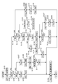
- FIG. 2 is a flowchart of the shift control process according to the first embodiment.
- the process of the flowchart shown in FIG. 2 is executed by the controller 1 at a predetermined cycle (for example, every several tens of milliseconds).
- the control according to this flowchart is a control mode (hereinafter referred to as “normal transmission mode”) in which the gear ratio is variably controlled in accordance with the driving state and a continuously variable transmission, as if it is a stepped transmission.
- Control of continuously variable transmission 10 while switching between a control mode hereinafter referred to as “pseudo stepped upshift mode” in which an upshift is performed after increasing the engine speed and accelerating in conjunction with an increase in vehicle speed I do.
- the controller 1 detects the accelerator pedal opening APO, the vehicle speed VSP, the engine speed Ne, and the like based on the detection values from the sensors in the background separately from the processing of this flowchart.
- step S101 the current accelerator pedal opening APO, vehicle speed VSP, and engine speed Ne are acquired.
- step S102 the current control mode is described as a normal shift mode (hereinafter referred to as a normal shift mode Mnor) based on a pseudo stepped upshift mode flag (hereinafter referred to as a pseudo stepped upshift mode flag Fstp). ) Or pseudo stepped upshift mode (hereinafter referred to as pseudo stepped upshift mode Mstp). If the pseudo stepped upshift mode flag Fstp is set (the value of the pseudo stepped upshift mode flag Fstp is 1), it is determined that the control mode is the pseudo stepped upshift mode Mstp, and step S113 is performed.
- the pseudo stepped upshift mode flag Fstp has an initial value of 0, and is set in the process of step S107 when it is determined in the subsequent step S103 that the control mode is the pseudo stepped upshift mode Mstp. Is done.
- step S103 based on each value acquired in step S101, it is determined whether the current control mode is the normal transmission mode Mnor or the pseudo stepped upshift mode Mstp. If it is determined that the normal transmission mode Mnor, the process proceeds to step S104. If it is determined that the pseudo stepped upshift mode Mstp is selected, the process proceeds to step S107.
- the controller 1 is a differential value of the accelerator pedal opening APO when the accelerator pedal opening APO is equal to or greater than an accelerator pedal opening threshold (hereinafter referred to as an accelerator pedal opening threshold APO1).
- the accelerator pedal opening threshold APO1 and the accelerator pedal opening speed threshold dAPO1 are thresholds for determining that the driver has requested acceleration.
- the accelerator pedal opening APO can be detected in 8 steps, for example, an opening (2/8 or 3/8) of 2 or 3 of the 8 steps can be set as the accelerator pedal opening threshold APO1.
- the accelerator pedal opening speed threshold value dAPO1 can be set to 60 [deg / s] in the stepping direction, for example, but neither threshold value is limited to the exemplified values.
- the driver may It is determined that the travel is in balance with the non-travel resistance including the drive resistance), and the normal shift mode Mnor is determined.
- the normal transmission mode Mnor the process proceeds to step S104, and the target transmission ratio of the continuously variable transmission 10 (hereinafter referred to as the target transmission ratio Ip) is the target transmission ratio in the normal transmission mode Mnor.
- the normal target speed ratio Inor the normal target speed ratio
- the normal target speed ratio Inor is determined by a conventionally known method based on the accelerator pedal opening APO, the vehicle speed VSP, and the engine speed Ne.
- the controller 1 has a target input shaft rotational speed corresponding to the target input shaft rotation speed from the vehicle speed VSP and the accelerator pedal opening APO based on the map.
- the normal target speed ratio Inor is determined by setting the engine speed during control (hereinafter referred to as the engine speed Ne0 during normal control).
- the set normal engine speed Ne0 is set as a new target engine speed (hereinafter referred to as target engine speed tNe).
- step S106 the continuously variable transmission 10 is shift-controlled so that the engine speed Ne matches the target engine speed tNe.
- the driver requests acceleration. Is determined to be the pseudo stepped upshift mode Mstp.
- the process proceeds to step S107, and the controller 1 first sets the pseudo stepped upshift mode flag Fstp to 1.
- step S108 the downshift amount of the gear ratio is set so as to satisfy the driver's acceleration request. Specifically, the driver's intention to accelerate is obtained from the accelerator pedal opening APO and the accelerator pedal opening speed dAPO. Then, the shift characteristic of the downshift corresponding to this acceleration intention is selected. Then, based on the selected speed change characteristic, a speed ratio equivalent change amount (hereinafter referred to as a speed ratio equivalent change amount ⁇ Ne1) that is a change amount of the engine speed Ne corresponding to the change amount of the speed ratio for downshifting according to the vehicle speed VSP. Is calculated). In step S109, a new target engine speed tNe is calculated by adding the change ratio equivalent change amount ⁇ Ne1 to the current target engine speed tNe.
- a speed ratio equivalent change amount hereinafter referred to as a speed ratio equivalent change amount ⁇ Ne1
- step S110 it is determined whether or not the operating point defined by the plurality of parameters including the new target engine speed tNe is within a region where there is a risk of causing a shift failure (hereinafter referred to as an NG region). If it is within the NG area, the process proceeds to step S111, and an NG area flag (hereinafter referred to as NG area flag Fng) is set to 1. On the other hand, if it is outside the NG area, the process proceeds to step S112, and the NG area flag Fng is set to 0. Here, the NG area will be described.
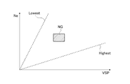
- FIG. 9 is an engine characteristics NG area map of the first embodiment
- FIG. 10 is a gear ratio characteristics NG area map of the first embodiment.
- the shift speed cannot be secured or downshifting has been performed. However, there is a region where the engine speed Ne cannot be increased and sufficient acceleration cannot be obtained.
- the operating point defined by the engine speed Ne (or Nt) and the vehicle speed VSP (or OutRev) is within the area indicated by the hatched area in FIG. 10, the speed of the continuously variable transmission 10 cannot be sufficiently secured.
- An area exists. This NG area is an area affected by vehicle specifications, and is specified by experiments or the like. It is determined whether or not the operating point is within the NG region in these multiple characteristics.
- the in-NG region flag Fng is set to 1.
- the input shaft speed Nt, target speed ratio Ip, target speed ratio change amount ⁇ Ip, output speed OutRev, target engine speed change amount ⁇ tNe, engine torque Trp change amount, stepless speed change The characteristics may be defined using a plurality of parameters such as the actual hydraulic pressure of the machine 10 to specify whether or not the operating point is within the NG region. Then, based on the newly calculated target engine speed tNe, shift control is performed in step S106. After the process of step S106, the process according to this flowchart is temporarily terminated.
- acceleration control by the first downshift performed after the transition to the pseudo stepped upshift mode Mstp by the processing of steps S108, S109, and S106 is referred to as "initial acceleration”.
- initial acceleration first, downshift control is performed so as to respond to the driver's acceleration request.
- step S112 which will be described later, until the engine rotational speed Ne reaches the upshift determination rotational speed, acceleration control for continuously changing the gear ratio to the downshift side is performed in steps S113 and S114 to accelerate the vehicle.
- the acceleration control for continuously changing the gear ratio to the downshift side after the initial acceleration until the first upshift occurs is called “low shift”.
- the shift control for suppressing the change amount of the gear ratio in the pseudo stepped upshift mode Mstp after the first upshift is completed is referred to as “linear shift”.
- step S113 it is determined whether or not the pseudo stepped upshift mode Mstp is continued. .
- the stepped pseudo upshift mode flag Fstp is set to 1 in step S107.
- the process proceeds to S113. The process of shifting from step S102 to step S113 is continued until the end of the pseudo stepped upshift mode Mstp is determined and the pseudo stepped upshift mode flag Fstp is reset to zero.
- step S113 is performed when the accelerator pedal opening APO is less than a second accelerator pedal opening threshold (hereinafter referred to as accelerator pedal opening APO2) or when the accelerator pedal is opened.
- accelerator pedal opening APO2 a second accelerator pedal opening threshold
- accelerator pedal opening speed dAPO2 the second accelerator pedal operation speed threshold
- the pseudo stepped upshift mode Mstp ends. Is determined. If the pseudo stepped upshift mode Mstp is not terminated, it is determined that the pseudo stepped upshift mode Mstp continues.
- the accelerator pedal opening APO2 and the accelerator pedal opening speed dAPO2 are threshold values for determining that the acceleration request by the driver has ended.
- the accelerator pedal opening APO2 is, for example, the same value as the accelerator pedal opening threshold APO1 in step S103 described above, that is, about two or three of the eight steps (2/8 or 3/8). It can be.
- the accelerator pedal opening speed dAPO2 can be set to, for example, -60 [deg / s] in the stepping direction (or 60 [deg / s] in the stepping back direction), but both threshold values are limited to the exemplified values. Is not to be done.
- step S130 When it is determined that the pseudo stepped upshift mode Mstp has not ended (the pseudo stepped upshift mode Mstp continues), the process proceeds to step S114.
- step S114 it is determined whether or not the NG area flag Fng is 0. If it is 0, it is determined that the flag is out of the NG area, and the process proceeds to step S115. Proceed to S121.
- FIG. 5 is a gear ratio change amount map of the first embodiment.
- the horizontal axis is a time axis, and shifts to the right side of FIG.
- a fixed value is adopted as the speed ratio change amount is shown.
- the first gear ratio change amount hereinafter referred to as the first gear ratio change amount (hereinafter referred to as the first gear ratio).
- a low shift is performed (hereinafter referred to as a normal low shift).
- the target gear ratio change amount ⁇ Ip after the initial acceleration is referred to as a second gear ratio change amount (hereinafter referred to as a second gear ratio change amount D2 ( ⁇ first gear ratio change amount D1)).
- a low shift is performed in which the amount of downshift is suppressed compared to the normal low shift (hereinafter referred to as a suppressed low shift).
- step S115 first, as an upshift determination rotation speed (hereinafter referred to as an upshift determination rotation speed Nup), a first upshift determination rotation speed (hereinafter referred to as a first upshift determination rotation speed Nup1).
- the first upshift determination rotational speed Nup1 is a shift control (corresponding to initial acceleration) based on the downshift set in the above-described step S108, and then performs an upshift at any timing during normal low shift execution. It is a value that decides.
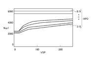
- FIG. 3 is an upshift determination rotation speed map of the first embodiment. The upshift determination rotation speed map illustrated in FIG.
- FIG. 3 is a map in which the correspondence relationship between the vehicle speed VSP and the first upshift determination rotation speed Nup1 is set for each accelerator pedal opening APO.
- the accelerator pedal opening APO is set so as to be detected in eight stages as described above.
- the vehicle speed VSP and the engine speed Ne for each of the six stages of accelerator pedal opening APO from 3/8 to 8/8, which are the judgment conditions for the pseudo stepped upshift mode Mstp, are shown.
- Correspondence is shown.
- the upshift determination rotational speed map the lower the accelerator pedal opening APO, that is, the smaller the acceleration request by the driver, the lower the first upshift determination rotational speed Nup1 is selected, and the lower the engine rotational speed Ne. It is set to perform upshift control.
- the controller 1 acquires the first upshift determination rotation speed Nup1 with reference to the upshift determination rotation speed map illustrated in FIG. 3 from the accelerator pedal opening APO acquired in step S101 and the current vehicle speed VSP. As will be described later, the upshift determination rotational speed map is set so that the first upshift determination rotational speed Nup1 becomes lower as the driver's acceleration request is smaller.
- step S116 is the initial determination flag (hereinafter referred to as the initial determination flag F2nd) indicating that the first upshift has occurred and control is being performed for the second upshift set to 0? If it is set to 0, it is determined that the first upshift has occurred before proceeding to step S117, and if it is set to 1, the first upshift is performed. It is determined that it has occurred, and the process proceeds to step S119.
- step S117 the target gear ratio change amount ⁇ Ip in the low shift is set to the first gear ratio change amount D1.
- the first gear ratio change amount D1 is a value that can increase the engine speed Ne at the start of acceleration within a predetermined time to an engine speed Ne with high engine torque or engine output horsepower.
- the increase in the engine speed Ne is slow, and it is difficult to obtain the acceleration feeling expected by the driver.
- the driver depresses the accelerator pedal with the intention of acceleration if the target engine speed tNe corresponding to the accelerator pedal opening APO is low, the driving force at the start of acceleration becomes low. Ascending slows and it is difficult to obtain the acceleration feeling expected by the driver. Therefore, even if the engine torque and engine output horsepower at the engine speed Ne at the start of acceleration are low and acceleration is difficult, the engine speed Ne is effectively increased by setting the target gear ratio change amount ⁇ Ip. The engine torque and engine output horsepower can be secured and accelerated.
- the engine speed increase amount ⁇ Ne2 the first engine speed change amount ⁇ Ne21 is set.
- the engine speed increase amount ⁇ Ne2 represents an amount by which the engine speed Ne increases per control cycle in the pseudo stepped upshift mode Mstp.
- step S119 since the control is performed for the second upshift, the low shift is switched to the linear shift. Specifically, the driver's intention to accelerate is obtained from the accelerator pedal opening APO and the accelerator pedal opening speed dAPO. Next, an upshift speed characteristic corresponding to the acceleration intention is selected. Then, a linear engine speed change amount (hereinafter referred to as a linear engine speed change amount ⁇ Ne0) that is a change amount of the engine speed Ne according to the change amount of the speed ratio in the upshift according to the vehicle speed VSP from the selected speed change characteristic. In step S120, the engine speed increase amount ⁇ Ne2 is set to the linear engine speed change amount ⁇ Ne0.
- a linear engine speed change amount hereinafter referred to as a linear engine speed change amount ⁇ Ne0
- step S121 since it is determined in step S114 that it is in the NG region, the upshift determination rotation speed Nup is set to the second upshift determination rotation speed Nup2 that is smaller than the first upshift determination rotation speed Nup1.
- the first upshift determination rotation speed Nup1 is obtained from the upshift determination rotation speed map of FIG. 3, and a value obtained by subtracting a predetermined amount is set as the second upshift determination rotation speed Nup2.
- an upshift determination rotation speed map for suppressing low shift may be provided separately. The operation of the second upshift determination rotational speed Nup2 will be described later.
- step S122 the target gear ratio change amount ⁇ Ip in the low shift is set to the second gear ratio change amount D2.
- the second speed ratio change amount D2 is smaller than the first speed ratio change amount D1.
- the engine speed increase amount ⁇ Ne2 the second engine speed change amount ⁇ Ne22 is set.
- the engine speed Ne cannot be increased effectively, or the continuously variable transmission 10 may not be able to shift quickly.
- the target speed ratio change amount ⁇ Ip is set to the first speed ratio change amount D1
- the driving force cannot be secured and the vehicle speed VSP cannot be expected to increase. Therefore, in the suppression low shift, the driving force is ensured while suppressing the increase in the engine speed Ne by suppressing the amount of downshift compared to the normal low shift.
- step S124 the engine speed Ne acquired in step S101 is compared with the first upshift determination speed Nup1 acquired in step S115, and whether or not the engine speed Ne exceeds the first upshift determination speed Nup1 Determine whether.
- the process proceeds to step S125.
- the engine speed Ne exceeds the first upshift determination speed Nup1
- the process proceeds to step S127.
- step S125 a new target engine speed tNe is calculated by adding the engine speed increase amount ⁇ Ne2 to the current target engine speed tNe. Then, based on the newly calculated target engine speed tNe, shift control is performed in step S106.
- step S106 the process according to this flowchart is temporarily terminated.
- the engine speed Ne is increased by performing control so as to suppress the change in the gear ratio in the low shift and the linear shift.
- step S124 when the engine speed Ne exceeds the first upshift determination speed Nup1, the process proceeds to step S127, and upshift control is performed.
- a third engine speed change amount (hereinafter referred to as a third engine speed change amount ⁇ Ne3) that is a change amount of the engine speed Ne corresponding to the upshift amount is set.
- This change amount third engine speed change amount ⁇ Ne3 is a target engine speed that is newly set from the target engine speed tNe that is set at the time of the first downshift control determined to be the pseudo stepped upshift mode Mstp.
- tNe is set to a high value.
- the new target engine speed tNe which is a value obtained by subtracting the third engine speed change amount ⁇ Ne3 from the engine speed Ne0 during normal control, is determined at the time of the first downshift control determined as the pseudo stepped upshift mode Mstp.
- the third engine speed change amount ⁇ Ne3 is set so as to be higher than the set target engine speed tNe.
- the third engine speed change amount ⁇ Ne3 that is set thereafter is a value in which the newly calculated target engine speed tNe is higher than the target engine speed tNe at the time of upshift control set in the previous step S114. Is set to be
- the vehicle speed VSP is higher than that after the previous upshift due to the shift control according to the acceleration request by the driver. Therefore, the running resistance (for example, the air resistance and the internal resistance of the continuously variable transmission 10 and the engine 11) increases as the vehicle speed VSP increases. Therefore, the controller 1 corrects a value obtained by correcting the target engine speed tNe at the time of the previous upshift so as to be higher by the deficiency of the driving force due to the increase in running resistance, the third engine speed change amount ⁇ Ne3. Set as. By performing the upshift control in this way, the engine speed Ne is temporarily reduced. Thereby, an acceleration feeling like an upshift of the stepped transmission can be given to the driver.
- the running resistance for example, the air resistance and the internal resistance of the continuously variable transmission 10 and the engine 11
- step S127 a new target engine speed tNe having a downshift characteristic is calculated by subtracting the set third engine speed change amount ⁇ Ne3 from the current target engine speed tNe.
- step S106 shift control based on the newly calculated target engine speed tNe is performed.
- the NG area flag Fng is reset to 0 in step S128, and the initial determination flag F2nd is set to 1 in step S129.
- the process proceeds to step S115 in step S114, and the process to proceed to steps S119 and S120 is selected in step S116, and the process shifts to the linear shift.
- step S106 the process according to this flowchart is temporarily terminated.
- the controller 1 increases the engine speed Ne by suppressing the change in the gear ratio, and then controls the gear ratio to the upshift side to decrease the engine speed Ne. This is called “shift”. This gradual upshift is repeatedly performed under the control of steps S110 to S127 while the acceleration request is continued (while the pseudo stepped upshift mode Mstp is continued).
- step S113 If it is determined in step S113 that the pseudo stepped upshift mode Mstp has ended, the process proceeds to step S130, and the controller 1 displays the pseudo stepped upshift mode flag Fstp, the NG region flag Fng, and the initial determination flag F2nd. Reset to 0.
- step S131 as in step S104 described above, the transmission gear ratio normal target transmission gear ratio Inor in the normal transmission mode Mnor is set as the target transmission gear ratio Ip.
- step S132 the set engine speed Ne0 during normal control is set. Is set as the target engine speed tNe.
- step S106 shift control based on the newly calculated target engine speed tNe is performed. After the process of step S106, the process according to this flowchart is temporarily terminated. Through the above processing, shift control based on the driver's acceleration request is performed.
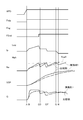
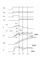
- FIG. 4 is a time chart showing the shift control outside the NG area of the first embodiment. This time chart shows the accelerator pedal opening APO, pseudo stepped upshift mode flag Fstp, NG region flag Fng, initial determination flag F2nd, target gear ratio Ip, engine speed Ne, vehicle speed VSP, from the top of FIG.
- G vehicle acceleration
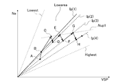
- FIG. 6 is a diagram showing the movement of the driving point in the plane defined by the vehicle speed and the engine speed by the shift control of the first embodiment.
- the timings A, B, G, H in FIG. 4 correspond to the points A, B, G, H in FIG. 6, and the arrows connecting the points in FIG. It shows how to do. 4 and 6 show a case where the operating point is determined to be outside the NG region at timing A.
- the vehicle is traveling in the normal transmission mode Mnor. That is, in this state, the accelerator pedal opening APO and the accelerator pedal opening speed dAPO are small enough not to satisfy the determination criterion of the pseudo stepped upshift mode Mstp.
- the pseudo stepped upshift mode flag Fstp is set to 1 in step S107
- the target engine speed tNe for initial acceleration is set in step S109
- the in-NG region flag Fng is set to 0 in step S111 Is done.
- the vehicle speed VSP is gradually accelerated. Further, the vehicle G derived from the inclination of the vehicle speed VSP also increases.
- the gear ratio at the point B after the initial acceleration is the target gear ratio Ip (1)
- the low gear shift is within the region on the lower gear ratio side than the target gear ratio Ip (1). Shifting control is performed toward.
- the locus of the driving point is described in a plane defined by the vehicle speed and the engine speed as shown in FIG. 6, the slope of the line connecting the driving point and the origin is expressed as a gear ratio.
- the engine speed Ne can be increased more quickly than when the engine speed Ne is increased at the target gear ratio Ip (1).
- step S127 If the engine speed Ne increases and is determined to be equal to or higher than the first upshift determination speed Nup1 in step S124 (timing C, point C), an upshift amount is set in step S127. Shift control based on the amount is performed. The target engine speed tNe at this time is set to a value that takes into account the increase in running resistance rather than the initial target engine speed tNe (timing B) when the pseudo stepped upshift mode Mstp is entered. When the upshift is executed, the initial determination flag F2nd is set to 1.
- a linear shift is executed along the speed ratio target speed ratio Ip (2) at the point D at the end of the upshift.
- the target engine speed tNe increases again and the engine speed Ne reaches the first upshift determination speed Nup1 (timing E, point E)
- an upshift is performed again in step S127 (timing F, point F).
- an upshift is performed step by step.
- the target engine speed tNe temporarily decreases, but the actual engine speed Ne increases with the subsequent increase in the vehicle speed VSP, and G also draws a graph that rises to the right accordingly.
- the engine speed Ne increases in conjunction with the increase in the vehicle speed VSP, and the G increases accordingly, thereby improving the acceleration feeling.
- a step upshift is performed after the low shift and the linear shift, so that the engine speed Ne increases continuously in conjunction with the increase in the vehicle speed VSP, and the acceleration fee is increased.
- the ring can be improved.
- FIG. 7 is an explanatory diagram showing the relationship among the engine speed, engine torque, fuel consumption rate, and output horsepower in the gear ratio control of the first embodiment.
- the equal fuel consumption rate is shown by a solid line in a contour line corresponding to the engine speed Ne and the engine torque Trq, and the center portion of the contour line is the driving condition with the best fuel consumption.
- the equal horsepower lines of the engine 11 are shown by dotted lines corresponding to the engine speed Ne and the engine torque Trq.
- steps S124 and S127 of FIG. 2 the engine speed Ne is controlled to be increased when the engine speed Ne exceeds the first upshift determination speed Nup1, and the engine speed Ne is decreased. By controlling in this way, an increase in the engine speed Ne can be suppressed, an appropriate engine output corresponding to the accelerator pedal opening APO can be achieved, and driving can be continued in the vicinity of the optimum fuel consumption conditions. .
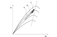
- FIG. 8 is an explanatory diagram showing the relationship between the engine speed and the output horsepower in the gear ratio control of the first embodiment.
- the output horsepower of the engine 11 has a characteristic line with respect to the engine speed Ne for each opening of the throttle valve.
- the throttle valve opening and the accelerator pedal opening APO have the same relationship.
- the peak of the engine output horsepower Ps is in the vicinity of a predetermined engine speed Ne (indicated by a dotted line in the figure).
- Ne the engine output horsepower Ps peaks when the engine speed Ne is around 4000 to 6000 [rpm].
- the engine speed Ne exceeds the upshift determination speed Nup determined for each accelerator pedal opening APO, an upshift is performed, and the engine speed Ne is controlled to decrease. Yes.
- an increase in the engine speed Ne is suppressed, and the operation can be continued in a region where the efficiency of the power performance of the engine 11 is high.
- the shift to the pseudo stepped upshift mode is performed, and after performing the initial acceleration by performing the downshift in the linear shift, the change of the gear ratio is performed.
- the control which suppresses is performed and the noise and the discomfort to a driver
- the engine speed Ne exceeds the first upshift determination speed Nup1 set in step S115
- the engine speed Ne once decreased increases again as the vehicle speed VSP increases by upshifting. Acceleration feeling can be improved.
- this upshift is repeatedly performed (stepwise upshift), an excessive increase in the engine speed Ne can always be suppressed, and fuel efficiency can be improved by using a region where the engine efficiency is high even during acceleration. Further, since the upshift is performed at a lower engine speed Ne as the driver's acceleration request is smaller, the engine speed Ne is not increased even when the acceleration request is small, and deterioration of fuel consumption can be prevented.
- FIG. 11 is a time chart showing the shift control in the NG region of the first embodiment. This time chart shows the accelerator pedal opening APO, pseudo stepped upshift mode flag Fstp, NG region flag Fng, initial determination flag F2nd, target speed ratio Ip, engine speed Ne, vehicle speed VSP, from the top of FIG. About G, each state in the time-axis which goes from the left side to the right side is shown.
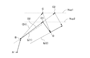
- FIG. 12 is an enlarged view showing the movement of the operating point in a plane defined by the vehicle speed and the engine speed by the shift control in the NG region of the first embodiment. Timings A, B, C, and D in FIG. 11 correspond to points A, B, C, and D in FIG. 12, and arrows connecting the points in FIG. 12 represent how the operating point moves with time. . 11 and 12 show a case where the operating point is determined to be in the NG region at timing A.
- FIG. 11 and 12 show a case where the operating point is determined to be in the NG region at timing A.
- the second speed ratio change amount D2 that is smaller than the first speed ratio change amount D1 set in step S117 when in the NG area is the target.
- the gear ratio at the point B after the initial acceleration is the target gear ratio Ip (1)
- the target gear ratio Ip (1) is lower than the target gear ratio Ip (1) due to the suppression low shift.
- the target gear ratio Ip (1) is not low shifted, the engine speed Ne cannot be effectively increased. Therefore, as in the comparative example indicated by the one-dot chain line in FIG. 11, the increase in the engine speed Ne tends to be delayed.
- the engine speed Ne can be increased more quickly than when the engine speed Ne is increased by the change ratio D1 of the first speed ratio or the target speed ratio Ip (1).
- the upshift determination rotational speed Nup is the same as the first upshift determination rotational speed Nup1, which is the same as the normal Low shift
- the upshift timing is delayed by the decrease in the rising gradient of the engine rotational speed Ne (point in FIG. 12). (See C2). Therefore, during the suppression low shift, the second upshift determination rotation speed Nup2 lower than the first upshift determination rotation speed Nup1 is set, and the upshift is performed at the same timing as the normal low shift (see point C1 in FIG. 12). Can be started.
- step S127 when the engine speed Ne increases and it is determined in step S124 that the second upshift determination speed Nup2 or higher (timing C, point C1), an upshift amount is set in step S127. Shift control based on the shift amount is performed.
- the target engine speed tNe at this time is set to a value that takes into account the increase in running resistance rather than the initial target engine speed tNe (timing B) when the pseudo stepped upshift mode Mstp is entered.
- the initial determination flag F2nd is set to 1.
- a linear shift is performed along the speed ratio target speed ratio Ip (2) at the point D at the end of the upshift.
- the target engine speed tNe increases again and the engine speed Ne reaches the first upshift determination speed Nup1 (timing E)
- an upshift is performed again in step S127 (timing F).
- an upshift is performed step by step.
- the target engine speed tNe temporarily decreases, but the actual engine speed Ne increases with the subsequent increase in the vehicle speed VSP, and G also draws a graph that rises to the right accordingly.
- the engine speed Ne increases in conjunction with the increase in the vehicle speed VSP, and the G increases accordingly, thereby improving the acceleration feeling.
- the quasi stepped upshift mode Mstp a state where the engine speed Ne increases continuously in conjunction with the increase in the vehicle speed VSP is performed continuously by performing the upshift after the suppression Low shift and the linear shift, Acceleration feeling can be improved.
- the normal transmission mode Mnor (first control mode), which variably controls the transmission ratio of the continuously variable transmission 10 that outputs the engine speed Ne steplessly and outputs it, and the speed ratio is increased.
- a pseudo step-up upshift mode Mstp (second control mode) that performs upshifting after the vehicle has accelerated by controlling the engine speed Ne to increase in conjunction with
- the pseudo stepped upshift mode Mstp is selected, the downshift is continuously performed until an upshift occurs.
- the pseudo stepped upshift mode Mstp is selected when at least one of the accelerator pedal opening APO and the accelerator pedal opening speed dAPO is equal to or greater than a predetermined value. Therefore, shift control according to the driver's intention to accelerate can be achieved.
- the amount of downshift is smaller than when the predetermined shift speed can be achieved.
- the target speed ratio change amount ⁇ Ip is not the first speed ratio change amount D1, but the second speed ratio change amount D2.
- the target speed ratio change amount ⁇ Ip is set as the second speed ratio change amount D2 when the engine speed Ne cannot be increased effectively or when the speed change speed cannot be secured. Therefore, it is possible to secure the driving force while suppressing the increase in the engine speed Ne.
- the upshift determination rotational speed Nup is set to the second upshift determination rotational speed Nup2 that is lower than the first upshift determination rotational speed Nup1 (the predetermined engine rotational speed is reduced). To do).
- the timing at which the engine speed Ne reaches the second upshift determination speed Nup2 can be substantially matched with the timing at which the engine speed Ne reaches the first upshift determination speed Nup1 in the normal Low shift, Even if it is a restrained low shift, it can be upshifted with the same rhythm as the normal low shift.
- the target speed ratio change amount ⁇ Ip is set to the first speed ratio change amount D1 and the second speed ratio change amount D2 which are fixed values.
- the value gradually increases with time.
- the locus of the driving point is described in a plane defined by the vehicle speed and the engine speed as shown in FIG. 6, the slope of the line connecting the driving point and the origin is expressed as a gear ratio.
- the tangent of the locus of the operating point in the section corresponding to the point B to the point C in FIG. 6 does not pass through the origin in FIG.
- the engine speed Ne in order to increase the engine speed Ne slowly in the early stage when the engine torque Trq and the engine output horsepower Ps are insufficient, and in the latter period when the engine torque Trq and the engine output horsepower Ps start to be secured,
- the engine speed Ne can be effectively increased.
- the following operational effects can be obtained in addition to the operational effects of (1) to (3), (5) and (6) of the first embodiment.
- (7) In the quasi stepped upshift mode Mstp, when the downshift is continuously performed until the upshift occurs, the downshift is performed so that the speed ratio change amount gradually increases. Therefore, the engine speed Ne can be effectively increased.
- the target speed ratio change amount ⁇ Ip is set to a fixed value set in advance.
- the larger the accelerator pedal opening APO and the accelerator pedal opening speed dAPO the larger the first speed ratio change amount D1 and the second speed change.
- a map that is an initial value of the ratio change amount D2 or D3, or an arithmetic expression may be provided.
- the engine speed Ne is effectively increased by the low shift according to the acceleration intention, and the driving force can be secured.
Landscapes
- Engineering & Computer Science (AREA)
- General Engineering & Computer Science (AREA)
- Mechanical Engineering (AREA)
- Control Of Transmission Device (AREA)
Abstract
Description
2 エンジン回転数センサ
3 入力軸回転数センサ
4 車速センサ
5 アクセルペダル開度センサ
10 無段変速機
11 エンジン
12 トルクコンバータ
ステップS102では、疑似有段アップシフトモードフラグ(以下、擬似有段アップシフトモードフラグFstpと記載する。)に基づいて、現在の制御モードが通常変速モード(以下、通常変速モードMnorと記載する。)であるか疑似有段アップシフトモード(以下、擬似有段アップシフトモードMstpと記載する。)であるかを判定する。擬似有段アップシフトモードフラグFstpがセットされている(擬似有段アップシフトモードフラグFstpの値が1である)場合は、制御モードが擬似有段アップシフトモードMstpであると判定してステップS113に移行する。擬似有段アップシフトモードフラグFstpがセットされていない(擬似有段アップシフトモードフラグFstpの値が0である)場合は、擬似有段アップシフトモードMstpではないと判定して、ステップS103に移行する。尚、擬似有段アップシフトモードフラグFstpは初期値が0であり、後のステップS103の処理において制御モードが擬似有段アップシフトモードMstpであると判定された場合に、ステップS107の処理においてセットされる。
ステップS105では、設定された通常制御時エンジン回転数Ne0を、新たな目標エンジン回転数(以下、目標エンジン回転数tNeと記載する。)として設定する。
ステップS106では、エンジン回転数Neが目標エンジン回転数tNeに一致するように、無段変速機10を変速制御する。このステップS106の処理後、本フローチャートによる処理を一旦終了する。
ステップS109では、変速比相当変化量ΔNe1を現在の目標エンジン回転数tNeに加算することで、新たな目標エンジン回転数tNeを算出する。
そして、この新たに算出された目標エンジン回転数tNeに基づいて、ステップS106において変速制御がなされる。このステップS106の処理後、本フローチャートによる処理が一旦終了する。
NG領域外のときは、初期加速後に一制御周期当たりの目標変速比Ipの変化量(以下、目標変速比変化量ΔIpと記載する。)を第1変速比変化量(以下、第1変速比変化量D1と記載する。)としてLowシフトを行う(以下、通常Lowシフトと記載する。)。一方、NG領域内のときは、初期加速後に目標変速比変化量ΔIpを第2変速比変化量(以下、第2変速比変化量D2(<第1変速比変化量D1)と記載する。)で通常Lowシフトよりもダウンシフト量を抑制したLowシフトを行う(以下、抑制Lowシフトと記載する。)。
ステップS115では、まず、アップシフト判定回転数(以下、アップシフト判定回転数Nupと記載する。)として、第1アップシフト判定回転数(以下、第1アップシフト判定回転数Nup1と記載する。)を設定する。第1アップシフト判定回転数Nup1とは、前述のステップS108において設定されたダウンシフトに基づいて変速制御(初期加速に相当)された後、通常Lowシフトを実行中のどのタイミングでアップシフトを行うかを決める値である。図3は実施例1のアップシフト判定回転数マップである。図3に例示するアップシフト判定回転数マップは、車速VSPと第1アップシフト判定回転数Nup1との対応関係が、アクセルペダル開度APOごとに設定されたマップである。なお、アクセルペダル開度APOは、前述のように8段階に検出されるように設定されている。図3に示す例では、そのうち、擬似有段アップシフトモードMstpの判定条件である3/8から8/8までの6段階のアクセルペダル開度APOそれぞれについて、車速VSPとエンジン回転数Neとの対応関係が示されている。このアップシフト判定回転数マップによると、アクセルペダル開度APOが小さいほど、すなわち運転者による加速要求が小さいほど、低い第1アップシフト判定回転数Nup1が選択されて、より低いエンジン回転数Neでアップシフト制御が行われるように設定されている。
ステップS117では、Lowシフトにおける目標変速比変化量ΔIpを第1変速比変化量D1にセットする。第1変速比変化量D1は、所定時間内に加速開始時のエンジン回転数Neを、エンジントルクやエンジン出力馬力が高いエンジン回転数Neまで上昇可能な値である。すなわち、車両負荷が高い状態、例えば高車速での走行中や登坂路を走行中では、エンジン回転数Neの上昇が遅くなり、運転者が期待した加速感が得られにくい。また、運転者が加速意図をもってアクセルペダルを踏み込んだとしても、アクセルペダル開度APOに応じた目標エンジン回転数tNeが低いと、加速開始時の駆動力が低くなり、やはり、エンジン回転数Neの上昇が遅くなり、運転者が期待した加速感が得られにくい。そこで、加速開始時のエンジン回転数Neにおけるエンジントルクやエンジン出力馬力が低く、加速しにくい場合であっても、目標変速比変化量ΔIpを設定することで、エンジン回転数Neを効果的に上昇させることができ、エンジントルクやエンジン出力馬力を確保して加速することができる。
ステップS118では、目標変速比変化量ΔIp=第1変速比変化量D1に応じたエンジン回転数Neの変化量である第1エンジン回転数変化量(以下、第1エンジン回転数変化量ΔNe21と記載する。)を演算し、エンジン回転数上昇量ΔNe2=第1エンジン回転数変化量ΔNe21を設定する。エンジン回転数上昇量ΔNe2とは、擬似有段アップシフトモードMstpのときに、一制御周期当たりにエンジン回転数Neが上昇する量を表す。
ステップS119では、2回目のアップシフトに向けて制御しているため、Lowシフトからリニアシフトへ切り替える。具体的には、アクセルペダル開度APOとアクセルペダル開速度dAPOとから、運転者の加速意図をマップにより求める。次に、この加速意図に応じたアップシフトの変速特性を選択する。そして、選択された変速特性から車速VSPに応じてアップシフトにおける変速比の変化量に応じたエンジン回転数Neの変化量であるリニアエンジン回転数変化量(以下、リニアエンジン回転数変化量ΔNe0と記載する。)を算出し、ステップS120において、エンジン回転数上昇量ΔNe2をリニアエンジン回転数変化量ΔNe0に設定する。
ステップS121では、ステップS114においてNG領域内であると判断されたため、アップシフト判定回転数Nupを第1アップシフト判定回転数Nup1よりも小さな値である第2アップシフト判定回転数Nup2に設定する。第2アップシフト判定回転数Nup2は、図3のアップシフト判定回転数マップから第1アップシフト判定回転数Nup1を求め、そこから所定量を減算した値を第2アップシフト判定回転数Nup2として設定してもよいし、別途、抑制Lowシフト用のアップシフト判定回転数マップを備えていてもよい。第2アップシフト判定回転数Nup2の作用については、後述する。
ステップS122では、Lowシフトにおける目標変速比変化量ΔIpを第2変速比変化量D2にセットする。第2変速比変化量D2は第1変速比変化量D1よりも小さな値である。
ステップS123では、目標変速比変化量ΔIp=第2変速比変化量D2に応じたエンジン回転数Neの変化量である第2エンジン回転数変化量(以下、第2エンジン回転数変化量ΔNe22と記載する。)を演算し、エンジン回転数上昇量ΔNe2=第2エンジン回転数変化量ΔNe22を設定する。
ステップS124では、ステップS101で取得したエンジン回転数NeとステップS115で取得した第1アップシフト判定回転数Nup1とを比較して、エンジン回転数Neが第1アップシフト判定回転数Nup1を超えたか否かを判定する。エンジン回転数Neが第1アップシフト判定回転数Nup1以下である場合は、ステップS125に移行する。エンジン回転数Neが第1アップシフト判定回転数Nup1を超えた場合は、ステップS127に移行する。
ステップS125では、エンジン回転数上昇量ΔNe2を現在の目標エンジン回転数tNeに加算することで、新たな目標エンジン回転数tNeを算出する。そして、この新たに算出された目標エンジン回転数tNeに基づいて、ステップS106において変速制御がなされる。このステップS106の処理後、本フローチャートによる処理が一旦終了する。このように、擬似有段アップシフトモードMstpと判定した後、Lowシフト及びリニアシフトにおいて変速比の変化を抑制するように制御することで、エンジン回転数Neが増大する。
ステップS106の処理後、本フローチャートによる処理が一旦終了する。このように、コントローラ1が、変速比の変化を抑制して、エンジン回転数Neを増大させた後、変速比をアップシフト側に制御してエンジン回転数Neを減少させることを、「段々アップシフト」と呼ぶ。この段々アップシフトは、加速要求が継続している間(擬似有段アップシフトモードMstpが継続している間)は、ステップS110からS127の制御によって、繰り返し実施される。
以上の処理によって、運転者の加速要求に基づいた変速制御がなされる。
図4は、実施例1のNG領域外における変速制御を表すタイムチャートである。このタイムチャートは、図4の上方から、アクセルペダル開度APO、擬似有段アップシフトモードフラグFstp、NG領域内フラグFng、初回判定フラグF2nd、目標変速比Ip、エンジン回転数Ne、車速VSP、車両加速度(以下、Gと記載する。)について、左側から右側へと向かう時間軸での、それぞれの状態を示す。また、図6は、実施例1の変速制御により車速とエンジン回転数で規定される平面内において、運転点の移動を表記した図である。図4のタイミングA、B、、、G,Hは、図6の点A、B、、、G,Hに対応し、図6中の各点を結ぶ矢印は、時間経過と共に運転点が移動する様子を表す。尚、図4,6は、タイミングAにおいて運転点がNG領域外と判定された場合を示す。
その後、再び目標エンジン回転数tNeが上昇し、エンジン回転数Neが第1アップシフト判定回転数Nup1に到達すると(タイミングE、点E)、ステップS127において再度アップシフトが行われる(タイミングF、点F)。その後も、(タイミングG、点G)→(タイミングH、点H)への動きに示すように、段々アップシフトが行われる。この段々アップシフトの実行により、目標エンジン回転数tNeが一旦下がるが、その後の車速VSPの伸びと共に実際のエンジン回転数Neも伸び、Gもそれに対応して右上がりのグラフを描く。
その後、エンジン回転数NeがステップS115で設定した第1アップシフト判定回転数Nup1を超えた場合に、アップシフトすることにより、車速VSPの伸びと共に、一旦低下したエンジン回転数Neが再び上昇することによる加速フィーリングを向上できる。また、このアップシフトは繰り返し行われるので(段々アップシフト)、常にエンジン回転数Neの過大な上昇を抑制することができ、加速時にもエンジン効率が高い領域を用いることで、燃費を向上できる。また、運転者の加速要求が小さいほど低いエンジン回転数Neでアップシフトを行うので、加速要求が小さいときにもエンジン回転数Neを高くすることがなく、燃費の悪化を防止できる。
図11は、実施例1のNG領域における変速制御を表すタイムチャートである。このタイムチャートは、図11の上方から、アクセルペダル開度APO、擬似有段アップシフトモードフラグFstp、NG領域内フラグFng、初回判定フラグF2nd、目標変速比Ip、エンジン回転数Ne、車速VSP、Gについて、左側から右側へと向かう時間軸での、それぞれの状態を示す。また、図12は、実施例1のNG領域内における変速制御により車速とエンジン回転数で規定される平面内において、運転点の移動を表記した拡大図である。図11のタイミングA、B、C、Dは、図12の点A、B、C、Dに対応し、図12中の各点を結ぶ矢印は、時間経過と共に運転点が移動する様子を表す。尚、図11,12は、タイミングAにおいて運転点がNG領域内と判定された場合を示す。
その後、再び目標エンジン回転数tNeが上昇し、エンジン回転数Neが第1アップシフト判定回転数Nup1に到達すると(タイミングE)、ステップS127において再度アップシフトが行われる(タイミングF)。その後も、段々アップシフトが行われる。この段々アップシフトの実行により、目標エンジン回転数tNeが一旦下がるが、その後の車速VSPの伸びと共に実際のエンジン回転数Neも伸び、Gもそれに対応して右上がりのグラフを描く。
(1)エンジン回転数Neを無段階に変速して出力する無段変速機10の変速比を無段階に可変制御する通常変速モードMnor(第1の制御モード)と、変速比を車速の上昇に連動してエンジン回転数Neが上昇するように制御して車両が加速した後にアップシフトを行う擬似有段アップシフトモードMstp(第2の制御モード)とのうち、運転者の加速要求に応じて一方の制御モードを選択し、選択された制御モードに基づき変速比を制御する場合に、擬似有段アップシフトモードMstpが選択されたときは、アップシフトが発生するまで継続的にダウンシフトする。
よって、アクセルペダル踏み込み時のエンジン回転数NeにおけるエンジントルクTrqやエンジン出力馬力Psが低く、加速しにくい場合であっても、継続的にダウンシフトすることで、エンジン回転数Neを効果的に上昇させることができ、エンジントルクTrqやエンジン出力馬力Psを確保して加速することができる。
よって、加速開始時のエンジン回転数Neが低く、エンジントルクTrq及びエンジン出力馬力Psが低い場合でも、素早くエンジン回転数Neを上昇させることで、エンジントルクTrq及びエンジン出力馬力Psを確保することができる。
よって、エンジン回転数Neの上昇を抑制しつつ駆動力を確保できる。
よって、エンジン回転数Neが第2アップシフト判定回転数Nup2に到達するタイミングを、通常Lowシフトにおいてエンジン回転数Neが第1アップシフト判定回転数Nup1に到達するタイミングと略一致させることができ、抑制Lowシフトであっても、通常Lowシフトと同じリズム感でアップシフトできる。
次に、他の実施例について説明する。実施例1では、初期加速後に目標変速比変化量ΔIpを固定値である第1変速比変化量D1や第2変速比変化量D2とした。これに対し、他の実施例では、図5のD3に示すように、時間経過と共に漸増する値とした。ここで、図6のように車速とエンジン回転数で規定される平面内において、運転点の軌跡を表記した場合、運転点と原点とを結ぶ線の傾きが変速比として表される。このとき、図6の点Bから点Cに相当する区間における運転点の軌跡の接線は、図6の原点を通ることは無い。この場合、エンジントルクTrqやエンジン出力馬力Psが不足する初期では、エンジン回転数Neをゆっくり上昇させ、エンジントルクTrqやエンジン出力馬力Psが確保され始める後期では、エンジン回転数Neを素早く上昇させるため、エンジン回転数Neを効果的に上昇させることができる。
以上説明したように、他の実施例にあっては実施例1の(1)~(3)、(5)及び(6)の作用効果に加えて、下記の作用効果を得ることができる。
(7)擬似有段アップシフトモードMstpにおいて、アップシフトが発生するまで継続的にダウンシフトするときは、変速比変化量が漸増するようにダウンシフトする。よって、エンジン回転数Neを効果的に上昇させることができる。
Claims (8)
- 無段変速機の変速比を無段階に可変制御する第1の制御モードと、前記変速比を有段階に制御して車速が上昇した後にアップシフトを行う第2の制御モードとのうち、運転者の加速要求に応じて前記第2の制御モードを選択したときは、前記アップシフトを行うまで継続的にダウンシフトすることを特徴とする自動変速機の制御方法。
- 請求項1に記載の自動変速機の制御方法において、
アクセルペダル開度とアクセルペダル開速度の少なくとも一方が所定値以上のときに前記第2の制御モードを選択することを特徴とする自動変速機の制御方法。 - 請求項1または2に記載の自動変速機の制御方法において、
前記第2の制御モードにおいて、アップシフトが発生するまで継続的にダウンシフトするときは、エンジントルク及びエンジン出力馬力が高いエンジン回転数まで上昇するようにダウンシフトすることを特徴とする自動変速機の制御方法。 - 請求項1ないし3いずれか一つに記載の自動変速機の制御方法において、
前記第2の制御モードにおいて、アップシフトが発生するまで継続的にダウンシフトするときは、変速比変化量が一定となるようにダウンシフトすることを特徴とする自動変速機の制御方法。 - 請求項1ないし3いずれか一つに記載の自動変速機の制御方法において、
前記第2の制御モードにおいて、アップシフトが発生するまでの間に継続的にダウンシフトするときは、変速比変化量が漸増するようにダウンシフトすることを特徴とする自動変速機の制御方法。 - 請求項1ないし5いずれか一つに記載の自動変速機の制御方法において、
加速開始時の走行状態が、所定の変速速度を達成できないおそれがある状態と判断したときは、所定の変速速度を達成できる場合に比べて、ダウンシフト量を小さくすることを特徴とする自動変速機の制御方法。 - 請求項6に記載の自動変速機の制御方法において、
前記第2の制御モードは、所定のエンジン回転数に到達したときにアップシフトを行うモードであり、
前記ダウンシフト量を小さくしたときは、前記所定のエンジン回転数を低くすることを特徴とする自動変速機の制御方法。 - 無段変速機と、
前記無段変速機の変速比を無段階に制御する第1の制御モードと、前記無段変速機の変速比を有段階に制御して車速が上昇した後にアップシフトを行う第2の制御モードとのうち、運転者の加速要求に応じて一方の制御モードを選択し、選択した制御モードに基づき前記無段変速機の変速比を制御するコントローラと、
を備え、
前記コントローラは、前記第2の制御モードを選択したときは、前記アップシフトを行うまで継続的にダウンシフトすることを特徴とする自動変速機。
Priority Applications (9)
| Application Number | Priority Date | Filing Date | Title |
|---|---|---|---|
| EP15908768.3A EP3379110B1 (en) | 2015-11-19 | 2015-11-19 | Automatic transmission and control method therefor |
| US15/770,800 US10533656B2 (en) | 2015-11-19 | 2015-11-19 | Automatic transmission and control method therefor |
| CN201580084701.0A CN108368934B (zh) | 2015-11-19 | 2015-11-19 | 自动变速器及其控制方法 |
| PCT/JP2015/082507 WO2017085828A1 (ja) | 2015-11-19 | 2015-11-19 | 自動変速機及びその制御方法 |
| MYPI2018701899A MY190185A (en) | 2015-11-19 | 2015-11-19 | Automatic transmission and control method therefor |
| BR112018009426-9A BR112018009426B1 (pt) | 2015-11-19 | Método de controle para controlar uma transmissão automática e transmissão automática | |
| RU2018122067A RU2671428C1 (ru) | 2015-11-19 | 2015-11-19 | Автоматическая трансмиссия и способ управления ею |
| MX2018005717A MX367702B (es) | 2015-11-19 | 2015-11-19 | Transmision automatica y metodo de control para la misma. |
| JP2017551458A JP6436244B2 (ja) | 2015-11-19 | 2015-11-19 | 自動変速機及びその制御方法 |
Applications Claiming Priority (1)
| Application Number | Priority Date | Filing Date | Title |
|---|---|---|---|
| PCT/JP2015/082507 WO2017085828A1 (ja) | 2015-11-19 | 2015-11-19 | 自動変速機及びその制御方法 |
Publications (1)
| Publication Number | Publication Date |
|---|---|
| WO2017085828A1 true WO2017085828A1 (ja) | 2017-05-26 |
Family
ID=58718519
Family Applications (1)
| Application Number | Title | Priority Date | Filing Date |
|---|---|---|---|
| PCT/JP2015/082507 Ceased WO2017085828A1 (ja) | 2015-11-19 | 2015-11-19 | 自動変速機及びその制御方法 |
Country Status (8)
| Country | Link |
|---|---|
| US (1) | US10533656B2 (ja) |
| EP (1) | EP3379110B1 (ja) |
| JP (1) | JP6436244B2 (ja) |
| CN (1) | CN108368934B (ja) |
| MX (1) | MX367702B (ja) |
| MY (1) | MY190185A (ja) |
| RU (1) | RU2671428C1 (ja) |
| WO (1) | WO2017085828A1 (ja) |
Families Citing this family (5)
| Publication number | Priority date | Publication date | Assignee | Title |
|---|---|---|---|---|
| MY190185A (en) * | 2015-11-19 | 2022-03-31 | Nissan Motor | Automatic transmission and control method therefor |
| WO2019074009A1 (ja) * | 2017-10-12 | 2019-04-18 | 三菱自動車工業株式会社 | 変速機の制御装置 |
| CN109654218A (zh) * | 2019-01-04 | 2019-04-19 | 丰疆智慧农业股份有限公司 | 自动变速插秧机及其应用 |
| JP7215380B2 (ja) * | 2019-09-19 | 2023-01-31 | トヨタ自動車株式会社 | 車両の変速制御装置 |
| CN111059278B (zh) * | 2019-12-30 | 2021-08-20 | 潍柴动力股份有限公司 | 变速箱换挡控制方法、装置、设备及存储介质 |
Citations (2)
| Publication number | Priority date | Publication date | Assignee | Title |
|---|---|---|---|---|
| JPS62163835A (ja) * | 1986-01-11 | 1987-07-20 | Mazda Motor Corp | 無段変速機の制御装置 |
| JP5120102B2 (ja) * | 2008-06-26 | 2013-01-16 | 日産自動車株式会社 | 無段変速機の変速制御装置 |
Family Cites Families (14)
| Publication number | Priority date | Publication date | Assignee | Title |
|---|---|---|---|---|
| JP2002329140A (ja) | 2001-03-02 | 2002-11-15 | System Location Co Ltd | カタログデータ入力システム、及びこのカタログデータ入力システムで作成した車種データベースの検索システム |
| DE10357239A1 (de) * | 2003-12-08 | 2005-07-07 | Conti Temic Microelectronic Gmbh | Automatikgetriebe |
| US7869926B2 (en) * | 2006-12-19 | 2011-01-11 | Chrysler Group Llc | Fixed speed operation in a hybrid transmission |
| JP5173459B2 (ja) | 2008-01-31 | 2013-04-03 | 本田技研工業株式会社 | 無段変速機の変速制御方法 |
| US9234584B2 (en) * | 2010-08-31 | 2016-01-12 | Jatco Ltd | Control device of automatic transmission |
| JP5669779B2 (ja) * | 2012-03-19 | 2015-02-18 | ジヤトコ株式会社 | 無段変速機の変速制御装置 |
| JP6110676B2 (ja) * | 2013-02-01 | 2017-04-05 | 富士重工業株式会社 | 無段変速機の変速制御装置 |
| JP5906262B2 (ja) | 2014-01-15 | 2016-04-20 | 富士重工業株式会社 | 無段変速機の変速制御装置 |
| EP3232091A4 (en) * | 2014-12-11 | 2017-12-20 | Jatco Ltd | Control device for continuously variable transmission of vehicle |
| JP6274148B2 (ja) * | 2015-04-23 | 2018-02-07 | トヨタ自動車株式会社 | 車両の制御装置 |
| EP3290251B1 (en) * | 2015-04-27 | 2019-11-20 | Jatco Ltd. | Displayed rotational speed control apparatus for vehicle |
| US10190684B2 (en) * | 2015-11-18 | 2019-01-29 | GM Global Technology Operations LLC | Method and apparatus to control a continuously variable transmission |
| MY190185A (en) * | 2015-11-19 | 2022-03-31 | Nissan Motor | Automatic transmission and control method therefor |
| JP6972557B2 (ja) * | 2017-01-10 | 2021-11-24 | 三菱自動車工業株式会社 | 車両の制御装置 |
-
2015
- 2015-11-19 MY MYPI2018701899A patent/MY190185A/en unknown
- 2015-11-19 WO PCT/JP2015/082507 patent/WO2017085828A1/ja not_active Ceased
- 2015-11-19 CN CN201580084701.0A patent/CN108368934B/zh active Active
- 2015-11-19 RU RU2018122067A patent/RU2671428C1/ru active
- 2015-11-19 US US15/770,800 patent/US10533656B2/en active Active
- 2015-11-19 EP EP15908768.3A patent/EP3379110B1/en active Active
- 2015-11-19 JP JP2017551458A patent/JP6436244B2/ja active Active
- 2015-11-19 MX MX2018005717A patent/MX367702B/es active IP Right Grant
Patent Citations (2)
| Publication number | Priority date | Publication date | Assignee | Title |
|---|---|---|---|---|
| JPS62163835A (ja) * | 1986-01-11 | 1987-07-20 | Mazda Motor Corp | 無段変速機の制御装置 |
| JP5120102B2 (ja) * | 2008-06-26 | 2013-01-16 | 日産自動車株式会社 | 無段変速機の変速制御装置 |
Also Published As
| Publication number | Publication date |
|---|---|
| BR112018009426A2 (ja) | 2018-11-06 |
| EP3379110A4 (en) | 2018-12-05 |
| US10533656B2 (en) | 2020-01-14 |
| BR112018009426A8 (pt) | 2019-02-26 |
| CN108368934A (zh) | 2018-08-03 |
| MX2018005717A (es) | 2018-08-01 |
| CN108368934B (zh) | 2019-04-02 |
| RU2671428C1 (ru) | 2018-10-31 |
| EP3379110B1 (en) | 2020-11-04 |
| JPWO2017085828A1 (ja) | 2018-05-10 |
| US20180306312A1 (en) | 2018-10-25 |
| EP3379110A1 (en) | 2018-09-26 |
| JP6436244B2 (ja) | 2018-12-19 |
| MX367702B (es) | 2019-09-03 |
| MY190185A (en) | 2022-03-31 |
Similar Documents
| Publication | Publication Date | Title |
|---|---|---|
| JP5120102B2 (ja) | 無段変速機の変速制御装置 | |
| JP5388303B2 (ja) | 無段変速機の変速制御装置 | |
| JP6436244B2 (ja) | 自動変速機及びその制御方法 | |
| US20090319137A1 (en) | Output control device for internal combustion engine | |
| JP4678403B2 (ja) | 自動変速機の制御装置、制御方法、その方法を実現させるプログラムおよびそのプログラムを記録した記録媒体 | |
| JP2008239130A (ja) | 車両の制御装置 | |
| CN106065941B (zh) | 车辆的控制装置 | |
| JPWO2018051481A1 (ja) | 無段変速機の変速制御方法と変速制御装置 | |
| JP5821962B2 (ja) | 無段変速機の変速制御装置及び変速制御方法 | |
| JP2015124855A (ja) | 無段変速機の変速制御装置 | |
| US8620541B2 (en) | Vehicle driving-force control device | |
| JP5999188B2 (ja) | 車両制御装置および車両の制御方法 | |
| CN114072601B (zh) | 无级变速器的控制方法以及控制装置 | |
| JP2010107049A (ja) | 自動変速機の制御装置、制御方法、その方法を実現させるプログラムおよびそのプログラムを記録した記録媒体 | |
| JP4016822B2 (ja) | 無段変速機の変速制御装置 | |
| CN101389520A (zh) | 车辆驱动力控制设备及方法 | |
| JP2004162799A (ja) | 無段変速機の変速制御装置 | |
| JP4969078B2 (ja) | 自動変速機の変速制御装置 | |
| JP4206256B2 (ja) | 無段変速機の変速制御装置 | |
| JP2009216167A (ja) | 車両用無段変速機の変速制御装置 | |
| JP2009127763A (ja) | 自動変速機の制御装置 | |
| JP4340434B2 (ja) | 無段変速機の変速制御装置 | |
| JP4380320B2 (ja) | 無段変速機の変速制御装置 | |
| BR112018009426B1 (pt) | Método de controle para controlar uma transmissão automática e transmissão automática | |
| JPH11170893A (ja) | 車両用駆動力制御装置 |
Legal Events
| Date | Code | Title | Description |
|---|---|---|---|
| 121 | Ep: the epo has been informed by wipo that ep was designated in this application |
Ref document number: 15908768 Country of ref document: EP Kind code of ref document: A1 |
|
| ENP | Entry into the national phase |
Ref document number: 2017551458 Country of ref document: JP Kind code of ref document: A |
|
| WWE | Wipo information: entry into national phase |
Ref document number: 15770800 Country of ref document: US |
|
| WWE | Wipo information: entry into national phase |
Ref document number: MX/A/2018/005717 Country of ref document: MX |
|
| REG | Reference to national code |
Ref country code: BR Ref legal event code: B01A Ref document number: 112018009426 Country of ref document: BR |
|
| NENP | Non-entry into the national phase |
Ref country code: DE |
|
| WWE | Wipo information: entry into national phase |
Ref document number: 2018122067 Country of ref document: RU Ref document number: 2015908768 Country of ref document: EP |
|
| ENP | Entry into the national phase |
Ref document number: 112018009426 Country of ref document: BR Kind code of ref document: A2 Effective date: 20180509 |