WO2017085920A1 - 充電装置および電子機器 - Google Patents
充電装置および電子機器 Download PDFInfo
- Publication number
- WO2017085920A1 WO2017085920A1 PCT/JP2016/004846 JP2016004846W WO2017085920A1 WO 2017085920 A1 WO2017085920 A1 WO 2017085920A1 JP 2016004846 W JP2016004846 W JP 2016004846W WO 2017085920 A1 WO2017085920 A1 WO 2017085920A1
- Authority
- WO
- WIPO (PCT)
- Prior art keywords
- secondary battery
- threshold value
- charging
- charge
- level
- Prior art date
- Legal status (The legal status is an assumption and is not a legal conclusion. Google has not performed a legal analysis and makes no representation as to the accuracy of the status listed.)
- Ceased
Links
Images
















Classifications
-
- H—ELECTRICITY
- H01—ELECTRIC ELEMENTS
- H01M—PROCESSES OR MEANS, e.g. BATTERIES, FOR THE DIRECT CONVERSION OF CHEMICAL ENERGY INTO ELECTRICAL ENERGY
- H01M10/00—Secondary cells; Manufacture thereof
- H01M10/42—Methods or arrangements for servicing or maintenance of secondary cells or secondary half-cells
- H01M10/44—Methods for charging or discharging
- H01M10/441—Methods for charging or discharging for several batteries or cells simultaneously or sequentially
-
- H—ELECTRICITY
- H01—ELECTRIC ELEMENTS
- H01M—PROCESSES OR MEANS, e.g. BATTERIES, FOR THE DIRECT CONVERSION OF CHEMICAL ENERGY INTO ELECTRICAL ENERGY
- H01M10/00—Secondary cells; Manufacture thereof
- H01M10/42—Methods or arrangements for servicing or maintenance of secondary cells or secondary half-cells
- H01M10/44—Methods for charging or discharging
-
- H—ELECTRICITY
- H01—ELECTRIC ELEMENTS
- H01M—PROCESSES OR MEANS, e.g. BATTERIES, FOR THE DIRECT CONVERSION OF CHEMICAL ENERGY INTO ELECTRICAL ENERGY
- H01M10/00—Secondary cells; Manufacture thereof
- H01M10/42—Methods or arrangements for servicing or maintenance of secondary cells or secondary half-cells
- H01M10/48—Accumulators combined with arrangements for measuring, testing or indicating the condition of cells, e.g. the level or density of the electrolyte
-
- H—ELECTRICITY
- H02—GENERATION; CONVERSION OR DISTRIBUTION OF ELECTRIC POWER
- H02J—ELECTRIC POWER NETWORKS; CIRCUIT ARRANGEMENTS OR SYSTEMS FOR SUPPLYING OR DISTRIBUTING ELECTRIC POWER; SYSTEMS FOR STORING ELECTRIC ENERGY
- H02J7/00—Circuit arrangements for charging or discharging batteries or for supplying loads from batteries
-
- H—ELECTRICITY
- H02—GENERATION; CONVERSION OR DISTRIBUTION OF ELECTRIC POWER
- H02J—ELECTRIC POWER NETWORKS; CIRCUIT ARRANGEMENTS OR SYSTEMS FOR SUPPLYING OR DISTRIBUTING ELECTRIC POWER; SYSTEMS FOR STORING ELECTRIC ENERGY
- H02J7/00—Circuit arrangements for charging or discharging batteries or for supplying loads from batteries
- H02J7/02—Circuit arrangements for charging or discharging batteries or for supplying loads from batteries for charging batteries from AC mains by converters
-
- H—ELECTRICITY
- H02—GENERATION; CONVERSION OR DISTRIBUTION OF ELECTRIC POWER
- H02J—ELECTRIC POWER NETWORKS; CIRCUIT ARRANGEMENTS OR SYSTEMS FOR SUPPLYING OR DISTRIBUTING ELECTRIC POWER; SYSTEMS FOR STORING ELECTRIC ENERGY
- H02J7/00—Circuit arrangements for charging or discharging batteries or for supplying loads from batteries
- H02J7/34—Parallel operation in networks using both storage and other DC sources, e.g. providing buffering
-
- H—ELECTRICITY
- H02—GENERATION; CONVERSION OR DISTRIBUTION OF ELECTRIC POWER
- H02J—ELECTRIC POWER NETWORKS; CIRCUIT ARRANGEMENTS OR SYSTEMS FOR SUPPLYING OR DISTRIBUTING ELECTRIC POWER; SYSTEMS FOR STORING ELECTRIC ENERGY
- H02J7/00—Circuit arrangements for charging or discharging batteries or for supplying loads from batteries
- H02J7/34—Parallel operation in networks using both storage and other DC sources, e.g. providing buffering
- H02J7/342—The other DC source being a battery actively interacting with the first one, i.e. battery to battery charging
-
- H—ELECTRICITY
- H02—GENERATION; CONVERSION OR DISTRIBUTION OF ELECTRIC POWER
- H02J—ELECTRIC POWER NETWORKS; CIRCUIT ARRANGEMENTS OR SYSTEMS FOR SUPPLYING OR DISTRIBUTING ELECTRIC POWER; SYSTEMS FOR STORING ELECTRIC ENERGY
- H02J7/00—Circuit arrangements for charging or discharging batteries or for supplying loads from batteries
- H02J7/34—Parallel operation in networks using both storage and other DC sources, e.g. providing buffering
- H02J7/35—Parallel operation in networks using both storage and other DC sources, e.g. providing buffering with light sensitive cells
-
- H—ELECTRICITY
- H01—ELECTRIC ELEMENTS
- H01M—PROCESSES OR MEANS, e.g. BATTERIES, FOR THE DIRECT CONVERSION OF CHEMICAL ENERGY INTO ELECTRICAL ENERGY
- H01M10/00—Secondary cells; Manufacture thereof
- H01M10/05—Accumulators with non-aqueous electrolyte
- H01M10/052—Li-accumulators
- H01M10/0525—Rocking-chair batteries, i.e. batteries with lithium insertion or intercalation in both electrodes; Lithium-ion batteries
-
- H—ELECTRICITY
- H02—GENERATION; CONVERSION OR DISTRIBUTION OF ELECTRIC POWER
- H02J—ELECTRIC POWER NETWORKS; CIRCUIT ARRANGEMENTS OR SYSTEMS FOR SUPPLYING OR DISTRIBUTING ELECTRIC POWER; SYSTEMS FOR STORING ELECTRIC ENERGY
- H02J2207/00—Details of circuit arrangements for charging or discharging batteries or supplying loads from batteries
- H02J2207/40—Details of circuit arrangements for charging or discharging batteries or supplying loads from batteries adapted for charging from various sources, e.g. AC, DC or multivoltage
-
- H—ELECTRICITY
- H02—GENERATION; CONVERSION OR DISTRIBUTION OF ELECTRIC POWER
- H02J—ELECTRIC POWER NETWORKS; CIRCUIT ARRANGEMENTS OR SYSTEMS FOR SUPPLYING OR DISTRIBUTING ELECTRIC POWER; SYSTEMS FOR STORING ELECTRIC ENERGY
- H02J50/00—Circuit arrangements or systems for wireless supply or distribution of electric power
- H02J50/001—Energy harvesting or scavenging
-
- H—ELECTRICITY
- H02—GENERATION; CONVERSION OR DISTRIBUTION OF ELECTRIC POWER
- H02J—ELECTRIC POWER NETWORKS; CIRCUIT ARRANGEMENTS OR SYSTEMS FOR SUPPLYING OR DISTRIBUTING ELECTRIC POWER; SYSTEMS FOR STORING ELECTRIC ENERGY
- H02J7/00—Circuit arrangements for charging or discharging batteries or for supplying loads from batteries
- H02J7/80—Circuit arrangements for charging or discharging batteries or for supplying loads from batteries including monitoring or indicating arrangements
- H02J7/82—Control of state of charge [SOC]
-
- Y—GENERAL TAGGING OF NEW TECHNOLOGICAL DEVELOPMENTS; GENERAL TAGGING OF CROSS-SECTIONAL TECHNOLOGIES SPANNING OVER SEVERAL SECTIONS OF THE IPC; TECHNICAL SUBJECTS COVERED BY FORMER USPC CROSS-REFERENCE ART COLLECTIONS [XRACs] AND DIGESTS
- Y02—TECHNOLOGIES OR APPLICATIONS FOR MITIGATION OR ADAPTATION AGAINST CLIMATE CHANGE
- Y02E—REDUCTION OF GREENHOUSE GAS [GHG] EMISSIONS, RELATED TO ENERGY GENERATION, TRANSMISSION OR DISTRIBUTION
- Y02E60/00—Enabling technologies; Technologies with a potential or indirect contribution to GHG emissions mitigation
- Y02E60/10—Energy storage using batteries
Definitions
- the present invention relates to a charging device and an electronic device that accumulates power generated by energy harvesting and supplies the accumulated power to a charging target.
- a chargeable / dischargeable secondary battery is provided, power from a photovoltaic power generation module that performs commercial power supply or solar power generation is stored in the secondary battery, and the power stored in the secondary battery is externally stored.
- Some supply equipment electronic devices. Note that power generation by conversion of non-electric energy present in the environment into electrical energy, such as solar power generation, may be referred to as environmental power generation.
- Patent Document 1 discloses an example of a charging device as described above.
- the charging device disclosed in Patent Document 1 includes two batteries that can be charged and discharged. And the charging device currently disclosed by patent document 1 charges one battery with the generated electric power by environmental power generation, and discharges (supplies) the stored electric power of the other battery to an external device.
- the charging device disclosed in Patent Document 1 is charged when the remaining battery level of the battery being discharged is equal to or lower than a predetermined threshold value, and when the remaining battery level of the battery being charged is equal to or higher than the predetermined threshold value.
- the stored power is discharged to the external device to the battery that was in the middle, and the battery that was being discharged is charged by energy harvesting.
- the charging device disclosed in Patent Document 1 directly supplies power generated by energy harvesting to an external device when the remaining battery levels of both batteries are equal to or less than a predetermined threshold.
- the amount of power generated by energy harvesting is small compared to the amount of discharge to the external device, and the remaining battery level of both batteries is equal to or lower than a predetermined threshold, or the initial state In such cases, when the remaining battery levels of both batteries are equal to or less than the threshold value, the power generated by the environmental power generation is directly supplied to the external device.
- Some devices that receive power supply do not accept power supply if the supplied power does not meet the required current and voltage values. In this case, when the power generated by the environmental power generation is small or when the power fluctuation is large, the generated power is not used effectively, and power is wasted.
- An object of the present invention is to solve the above-described problems, to suppress the generation of waste of power in response to fluctuating generated power, and to quickly charge a device to be charged and an electronic device To provide equipment.
- the present inventors have intensively studied for the purpose of solving the above problems. Then, the present inventors provide a plurality of threshold values as threshold values for charge amount detection relating to the battery remaining amount of the secondary battery on the charging side, and a threshold value for discharge amount detection relating to the battery remaining amount of the secondary battery on the discharge side.
- the present invention is intended to advantageously solve the above-described problems, and the charging device of the present invention independently controls charging by the generated power of environmental power generation and discharging of the accumulated power to an external device.
- a plurality of possible secondary batteries, and one of the plurality of secondary batteries is a secondary battery on the charging side that is charged by the generated power of the environmental power generation, and other than the one secondary battery
- Charge / discharge control means for controlling the power stored in another secondary battery as a secondary battery on the discharge side for discharging to the external device, and for detecting a charge amount related to the remaining battery level of the secondary battery on the charge side
- At least one of a plurality of threshold values as a threshold value and a plurality of threshold values as a discharge amount detection threshold value regarding a remaining battery level of the secondary battery on the discharge side is set, and the charge / discharge control means
- the remaining battery level is Every time when one of a plurality of threshold values set as a threshold value is reached, and the remaining battery level of one secondary battery on the discharge side
- the present invention has an object to advantageously solve the above-described problem, and a battery of the secondary battery on the discharge side corresponding to each of the plurality of threshold values set as the threshold value for charge amount detection.
- a threshold value related to the remaining amount is set, and a threshold value related to the remaining battery level of the secondary battery on the charging side is set corresponding to each of the plurality of threshold values set as the discharge amount detection threshold value, and the charge / discharge control means
- the discharge side secondary battery set corresponding to the threshold is set.
- the secondary on the discharge side (charging side) for determining whether or not to switch the secondary battery to be charged / discharged according to the remaining battery level of the secondary battery on the charging side (discharge side)
- the threshold regarding the remaining battery level of the battery it is possible to suppress the generation of waste of power and to quickly charge the device to be charged.
- the present invention is intended to advantageously solve the above-described problem, and the threshold value related to the remaining battery level of the secondary battery on the discharge side increases as the threshold value set as the charge amount detection threshold value increases.
- the threshold value set as the discharge amount detection threshold value is larger, the larger threshold value is associated as the threshold value regarding the remaining battery level of the secondary battery on the charging side, and the charge / discharge control means
- the remaining battery level of the secondary battery on the charging side is equal to or higher than the threshold value set as the threshold value for detecting the charge amount
- the remaining battery level of the secondary battery on the discharging side is associated with the threshold value.
- the discharge-side secondary battery When the discharge-side secondary battery is smaller than the threshold value, the charging-side secondary battery is discharged, and the discharging-side secondary battery is charged with the generated power by the environmental power generation, and the discharging side Secondary of
- the battery remaining capacity of the battery is equal to or less than the threshold set as the discharge amount detection threshold, the remaining battery capacity of the charging-side secondary battery is greater than the threshold value for the charging-side secondary battery associated with the threshold value. In this case, the secondary battery on the charging side is discharged, and the secondary battery on the discharging side is charged with the power generated by the environmental power generation.
- the discharge side discharge side for determining whether or not to switch the secondary battery to be charged / discharged.
- the threshold value related to the remaining battery level of the secondary battery the charging of the secondary battery is stopped when the charged secondary battery is fully charged, and the power generated by energy harvesting is wasted.
- the secondary battery being discharged is in an empty state, it is possible to prevent the device from being stopped from being charged.
- the present invention has an object to advantageously solve the above-described problem, and in a state where power supply to the external device is stopped, the remaining battery level of the secondary battery on the charging side is the charge amount.
- the threshold value exceeds a minimum threshold value among a plurality of threshold values set as the detection threshold value, the connection with the external device is electrically disconnected and then reconnected. In this way, when the power supply to the external device is stopped and the electrical connection with the external device is disconnected, the external device is automatically reconnected to automatically connect the external device. Can resume charging.
- the said secondary battery performs constant current charge when charge is started, and when a battery voltage reaches a predetermined voltage, Switching to constant voltage charging is possible, and the maximum threshold value among the plurality of threshold values set as the charge amount detection threshold value is a remaining battery level of the secondary battery corresponding to the predetermined voltage or a value in the vicinity thereof. It is characterized by being. As described above, the maximum value of the charge amount detection threshold is equal to or less than the remaining battery level corresponding to the battery voltage at which the charging of the secondary battery is switched from constant current charging to constant voltage charging, and is a value in the vicinity of the remaining battery level. By doing so, the secondary battery can be charged at high speed to near the fully charged state.
- the present invention aims to solve the above-mentioned problem advantageously, and a power generation unit that generates power by the environmental power generation is detachable.
- a power generation unit that generates power by the environmental power generation is detachable.
- the portability of the charging device can be improved, and various power generation units can be mounted, so that the versatility of the charging device can be improved.
- the present invention is intended to advantageously solve the above-described problem, and the charge / discharge control unit stops power supply to the external device when the external device reaches full charge.
- the plurality of secondary batteries are sequentially charged by the environmental power generation until the remaining battery level reaches a predetermined charge stop threshold. In this way, when charging is stopped because the external device has reached full charge, each secondary battery is charged with the power generated by energy harvesting until the charging stop threshold is reached, and then the external device is charged. In this case, the charging of the external device can be started promptly.
- this invention aims at solving the said subject advantageously, A several threshold value can be set as the said charge stop threshold value, The said charging / discharging control means can be set as the said charge stop threshold value Among the plurality of threshold values, any threshold value selected by the user's operation is set as the charge stop threshold value. Thus, while setting any threshold selected by the user's operation as a charge stop threshold among a plurality of thresholds that can be set as the charge stop threshold, the deterioration of the performance of the secondary battery is suppressed. The battery can be charged to a level corresponding to the type of each secondary battery 11.
- the present invention has an object to advantageously solve the above-described problems, and the electronic device of the present invention can independently control charging by the generated power of environmental power generation and discharging of the accumulated power.
- one of the plurality of secondary batteries is a secondary battery on the charging side that is charged by the generated power of the environmental power generation, and other than the one secondary battery
- Charge / discharge control means for controlling the electric power stored in the secondary battery as a secondary battery on the discharge side for discharging to the load in the electronic device, and detecting the amount of charge related to the remaining battery level of the secondary battery on the charge side
- At least one of a plurality of threshold values as a threshold value for use and a plurality of threshold values as a discharge amount detection threshold value regarding a remaining battery level of the secondary battery on the discharge side is set, and the charge / discharge control means
- the remaining battery level of the secondary battery is the charge amount Whenever one of the plurality of thresholds set as the outgoing threshold is reached, the remaining battery level of one secondary battery on the discharge
- the charging device and the electronic apparatus it is possible to suppress the generation of waste of electric power corresponding to the fluctuating generated electric power and to promptly charge the device to be charged.
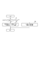
- FIG. 1 It is a block diagram which shows the structure of the charging device which concerns on one Embodiment of this invention. It is a flowchart which shows operation
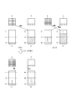
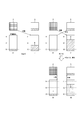
- movement by the charging / discharging control circuit shown in FIG. 3 is a flowchart showing an operation of the charging device shown in FIG. 1 when an event A occurs. It is a figure for demonstrating operation
- FIG. 3 is a flowchart showing an operation when an event B occurs in the charging apparatus shown in FIG. 1. It is a figure for demonstrating operation
- production of the event B of the charging device shown in FIG. 3 is a flowchart illustrating an operation when an event C occurs in the charging device illustrated in FIG. 1. It is a figure for demonstrating the operation
- production of the event C of the charging device shown in FIG. 3 is a flowchart showing an operation when an event D of the charging device shown in FIG. 1 occurs. It is a figure for demonstrating operation
- FIG. 2 is a flowchart illustrating an operation when an event E occurs in the charging device illustrated in FIG. 1. It is a figure for demonstrating operation
- production of the event E of the charging device shown in FIG. 2 is a flowchart showing an operation when an event F of the charging device shown in FIG. 1 occurs. It is a figure for demonstrating operation
- production of the event F of the charging device shown in FIG. 3 is a flowchart illustrating an operation when an event G occurs in the charging device illustrated in FIG. 1. It is a figure for demonstrating the operation
- FIG. 3 is a flowchart showing an operation when an event H occurs in the charging apparatus shown in FIG. 1. It is a figure for demonstrating the operation
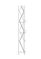
- 6 is a timing chart showing an operation according to Comparative Example 1; 6 is a timing chart showing an operation according to Comparative Example 1; 10 is a timing chart showing an operation according to Comparative Example 2. 10 is a timing chart showing an operation according to Comparative Example 2. It is a figure which shows the example of a setting of the threshold value for charge amount detection and the threshold value for discharge amount detection which concern on Example 1 of the charging device shown in FIG.
- FIG. 3 is a timing chart illustrating an operation according to the first embodiment of the charging device illustrated in FIG. 1.
- 3 is a timing chart illustrating an operation according to the first embodiment of the charging device illustrated in FIG. 1.
- It is a timing chart which shows the operation
- It is a timing chart which shows the operation
- It is a timing chart which shows the operation
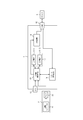
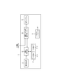
- FIG. 1 is a block diagram showing a configuration of a charging apparatus 1 according to an embodiment of the present invention.
- the charging device 1 according to the present embodiment accumulates the generated power of the environmental power generation unit 2 (power generation unit) that performs environmental power generation, and when the device 3 (external device) such as a mobile phone or a smartphone is connected, the stored power Is supplied to the device 3.
- the environmental power generation unit 2 power generation unit
- the device 3 external device
- a secondary battery 11 secondary batteries 11-1 and 11-2
- an AC Alternating Current
- -IF Interface
- charge / discharge control circuit charge / discharge control means
- the secondary battery 11 is a rechargeable secondary battery such as a lithium ion battery. Secondary batteries 11-1 and 11-2 constitute a power storage unit 17. In FIG. 1, the power storage unit 17 is configured by two secondary batteries 11, but the power storage unit 17 may be configured by three or more secondary batteries 11. Moreover, the capacity
- the AC-IF 12 can be connected to a commercial power source, converts AC power supplied from the commercial power source into DC power, and outputs the DC power to the charge / discharge control circuit 13.
- the charge / discharge control circuit 13 is supplied with power generated by solar power generation (DC power) from the environmental power generation unit 2 that performs solar power generation.
- the environmental power generation unit 2 includes a power generation module 21 that performs solar power generation, and a PV-IF 22 that connects the environmental power generation unit 2 and the charging device 1. Power generated by the power generation module 21 is input to the charge / discharge control circuit 13 via the PV-IF 22.
- As a power generation method by the environmental power generation unit 2 in addition to solar power generation using sunlight, wind power generation using wind power, vibration power generation using vibration, radio power generation using radio waves, etc. There are various methods by converting electrical energy into electrical energy.
- the energy harvesting unit 2 may be provided in the charging device 1.
- the energy harvesting unit 2 may be detachable from the charging device 1.
- the charging / discharging control circuit 13 individually controls charging / discharging of the secondary batteries 11-1, 11-2.
- the charge / discharge control circuit 13 includes a plurality of secondary batteries 11 constituting the power storage unit 17 by using power supplied from the environmental power generation unit 2 via the PV-IF 22 or power supplied from a commercial power source via the AC-IF 12. Among them, one secondary battery 11 is charged.
- the charge / discharge control circuit 13 discharges the stored power to the secondary battery 11 other than the secondary battery 11 being charged.
- the charge / discharge control circuit 13 sets a path for charging one secondary battery 11 and discharging another secondary battery 11 under the control of the system control circuit 16. The electric power discharged from the secondary battery 11 is input to the booster circuit 14.
- the charge / discharge control circuit 13 monitors the remaining battery level of the secondary battery 11 being charged and the remaining battery level of the secondary battery 11 being discharged, and according to the remaining battery level of each secondary battery 11. Then, charging of the secondary battery 11 being charged is stopped, discharging of the secondary battery 11 being discharged is stopped, and the secondary battery 11 that is charged and discharged is switched. Switching of the secondary battery 11 to be charged / discharged is to cause the secondary battery 11 that is being charged to start discharging and to cause the secondary battery 11 that is being discharged to start charging.
- the power storage unit 17 may be configured by three or more secondary batteries 11. When the power storage unit 17 includes three or more secondary batteries 11, one secondary battery 11 is charged and the other secondary batteries 11 discharge. In this case, the charging / discharging control circuit 13 switches charging / discharging between the secondary battery 11 being charged and one secondary battery 11 among the plurality of secondary batteries 11 being discharged.
- Booster circuit 14 boosts the voltage output from secondary battery 11 to a predetermined voltage necessary for power supply to device 3 and outputs the boosted voltage to external IF 15.
- the external IF 15 is, for example, a USB (Universal Serial Bus) interface, and is an interface for connecting the charging device 1 and the device 3 to be charged.
- the electric power output from the secondary battery 11 is boosted by the booster circuit 14 and supplied to the device 3 to be charged via the external IF 15.
- the system control circuit 16 controls charging / discharging of the secondary battery 11 by the charging / discharging control circuit 13.
- the system control circuit 16 connects the stored power from the secondary battery 11 other than the secondary battery 11 being charged by the generated power of the environmental power generation unit 2 or the generated power of the environmental power generation unit 2 to the external IF 15.
- the path of the charge / discharge control circuit 13 is connected to the external IF 15 so that the device 3 is supplied.
- the charge / discharge control circuit 13 uses the supplied electric power to The secondary batteries 11 are sequentially charged to a predetermined remaining battery level (for example, full charge), and when all the secondary batteries 11 are charged, the charging is stopped.
- the charge / discharge control circuit 13 When power is supplied from the environmental power generation unit 2 and power is supplied from the commercial power supply via the AC-IF 12, and the device 3 is not connected to the external IF 15, the charge / discharge control circuit 13 is connected to the AC-IF 12
- the secondary batteries 11 are sequentially charged to a predetermined remaining battery level (for example, full charge) with priority given to the power supplied from the commercial power source via the.
- the charge / discharge control circuit 13 is connected to the AC-IF 12
- the device 3 is charged with priority given to the power supplied from the commercial power source via the power, and the secondary battery 11 is charged with the power supplied from the energy harvesting unit 2.
- secondary batteries 11-1 and 11-2 may be referred to as secondary batteries B1 and B2, respectively.
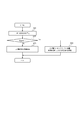
- the charge / discharge control circuit 13 sets a path for charging / discharging the secondary battery 11 by operating a switch constituting the path according to the initial setting (Ste S1).
- the secondary battery B2 and the device 3 are connected via the external IF 15, and the path where the secondary battery B1 and the energy harvesting unit 2 are connected is set as an initial setting.
- the charge / discharge control circuit 13 sets a path in which the secondary battery B2 is connected to the device 3 via the external IF 15 and the secondary battery B1 is connected to the energy harvesting unit 2 (step S2). In this state, the charging apparatus 1 enters a state of waiting for the connection of the device 3 to the external IF 15 or the supply of electric power from the energy harvesting unit 2.
- the charging apparatus 1 has a function (Plug & Play function) that automatically supplies the power stored in the secondary battery 11 to the device 3. Therefore, when the device 3 is connected to the external IF 15, the output of the secondary battery B 2 is boosted by the booster circuit 14 and supplied to the device 3 via the external IF 15. Moreover, the electric power from the environmental power generation part 2 is input into the charge / discharge control circuit 13, and the secondary battery B1 is charged.
- the initial setting described above is continued until the switching of the secondary battery 11 to be charged / discharged is performed as a result of the interrupt process for determining whether or not to switch the secondary battery 11 to be charged / discharged.
- the charge / discharge control circuit 13 discharges the remaining battery level of the secondary battery 11 (secondary battery on the charging side) being charged by the power generated by the environmental power generation unit 2 and the accumulated power to the device 3.
- the remaining battery level of the secondary battery 11 (secondary battery on the discharge side) is monitored, and the secondary battery 11 to be charged / discharged is switched according to the remaining battery level of each secondary battery 11.
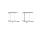
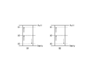
- the charge / discharge control circuit 13 has three threshold values X1, X2, X3 (threshold value X1> threshold value X2) regarding the remaining battery levels of the secondary batteries B1, B2. > Threshold X3) is set.
- the threshold value X1 is a value that is a predetermined amount less than the remaining battery level when the secondary battery 11 is fully charged (Full).
- the threshold value X1 corresponds to, for example, constant current / constant voltage charging that performs constant current charging when the secondary battery 11 starts charging and switches to constant voltage charging when the battery voltage reaches a predetermined voltage.
- the threshold value X3 is a value larger by a predetermined amount than the empty state (Empty) so that the secondary battery 11 is not overdischarged.
- the threshold value X3 is, for example, about 10 to 20% of the total capacity of the secondary battery 11.
- the threshold value X2 is the same value as the remaining battery level of the secondary battery 11 which is about half of the full charge.
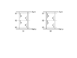
- the charge / discharge control circuit 13 determines the necessity of switching of the secondary battery 11 to be charged / discharged, and a threshold relating to the remaining battery level of the secondary battery 11 on the charge side (hereinafter referred to as a charge amount detection threshold). As a result, two threshold values X1 and X2 are set.
- the charge / discharge control circuit 13 is configured as shown in FIG. 4 when the remaining battery level of the secondary battery B1 becomes equal to or greater than a threshold value X2 (event A ) And when the remaining battery level of the secondary battery B1 becomes equal to or greater than the threshold value X1 (event B), the determination of whether or not to switch the secondary battery 11 to be charged / discharged is started.
- the charge / discharge control circuit 13 see FIG. 4 when the secondary battery B2 is a secondary battery on the charging side, the charge / discharge control circuit 13 (see FIG.
- the charge / discharge control circuit 13 determines whether or not the secondary battery 11 to be charged / discharged needs to be switched, with respect to the remaining battery level of the discharge-side secondary battery 11 (hereinafter referred to as a discharge amount detection threshold). 2), two threshold values X2 and X3 are set.
- the charge / discharge control circuit 13 is a time point (event E) when the remaining battery level of the secondary battery B1 becomes equal to or less than the threshold value X2.
- vent F the determination of whether or not to switch the secondary battery 11 to be charged / discharged is started.
- secondary battery B1 is a secondary battery on the charge side
- secondary battery B2 is a secondary battery on the discharge side
- the remaining battery level of secondary battery B1 is equal to or greater than threshold value X2.
- FIG. 5 is a flowchart showing the operation of the charging device 1 when the event A occurs.
- step S11 When the charge / discharge control circuit 13 detects that the remaining battery level of the secondary battery B1 on the charging side is equal to or higher than the threshold value X2, whether or not the remaining battery level of the secondary battery B2 on the discharging side is equal to or lower than the threshold value X3. Is determined (step S11).
- step S11 When it determines with the battery remaining charge of the secondary battery B2 being the threshold value X3 or less (step S11: Yes), as shown in FIG. 6, the charging / discharging control circuit 13 of the secondary battery 11 which performs charging / discharging is shown. Switching is performed so that the secondary battery B1 that is the secondary battery on the charging side discharges the stored power to the device 3, and the secondary battery B2 that is the secondary battery on the discharging side is charged with the generated power of the environmental power generation unit 2 (Step S12).
- the charge / discharge control circuit 13 stops discharging the secondary battery B2 because the secondary battery B2 is almost empty. Further, since the remaining battery level of the secondary battery B1 on the charging side is equal to or greater than the threshold value X2 and electric power is accumulated to some extent, the secondary battery B1 is caused to discharge. In this way, the device 3 can be continuously charged and the device 3 can be quickly charged. Further, since a certain amount of electric power is stored in the secondary battery B1, the secondary battery B1 does not become empty immediately after the discharge of the secondary battery B1 is started.
- step S11 When it is determined that the remaining battery level of the secondary battery B2 is not less than or equal to the threshold value X3 (the remaining battery level of the secondary battery B2 is greater than the threshold value X3) (step S11: No), the charge / discharge control circuit 13 As shown, the charging of the secondary battery B1 on the charging side and the discharging of the secondary battery B2 on the discharging side are continued (step S13).
- step S12 or step S13 the charge / discharge control circuit 13 returns to the normal process from the interrupt process (RETI: Return from Interrupt).
- the secondary battery B1 is a secondary battery on the charging side
- the secondary battery B2 is a secondary battery on the discharging side
- the remaining battery level of the secondary battery B1 is equal to or greater than the threshold value X1.
- FIG. 7 is a flowchart showing the operation of the charging device 1 when the event B occurs.
- the charge / discharge control circuit 13 determines whether or not the remaining battery level of the secondary battery B2 on the discharge side is equal to or less than the threshold value X2 (step S22).
- step S22 When it is determined that the remaining battery level of the secondary battery B2 is not less than or equal to the threshold value X2 (the remaining battery level of the secondary battery B2 is greater than the threshold value X2) (step S22: No), the charge / discharge control circuit 13 As shown, the secondary battery B2 continues to be discharged (step S23).
- step S22 When it determines with the battery remaining charge of the secondary battery B2 being below the threshold value X2 (step S22: Yes), as shown in FIG. 8, the charging / discharging control circuit 13 of the secondary battery 11 which performs charging / discharging is shown. Switching is performed so that the secondary battery B1 that is the secondary battery on the charging side discharges the stored power to the device 3, and the secondary battery B2 that is the secondary battery on the discharging side is charged with the generated power of the environmental power generation unit 2 (Step S24).
- the charging of the secondary battery B1 is stopped. If the discharge of the secondary battery B2 is continued in this state, the power generated by the environmental power generation unit 2 is not used for charging the secondary battery 11 and is wasted. Therefore, even though the remaining battery level of the secondary battery B2 is larger than the threshold value X3 and there is still room before the secondary battery B2 becomes empty, power is wasted by switching the secondary battery 11 to be charged / discharged. Can be prevented from occurring.
- step S23 or step S24 the charge / discharge control circuit 13 returns from the interrupt process to the normal process (RETI).
- secondary battery B1 is a secondary battery on the discharge side
- secondary battery B2 is a secondary battery on the charge side
- the remaining battery level of secondary battery B2 is equal to or greater than threshold value X2.
- FIG. 9 is a flowchart showing the operation of the charging device 1 when the event C occurs.
- step S31: Yes the charging / discharging control circuit 13 of the secondary battery 11 which performs charging / discharging is shown.
- the secondary battery B1 that was the secondary battery on the discharge side is charged with the power generated by the environmental power generation unit 2, and the stored power is discharged to the secondary battery B2 that was the secondary battery on the charge side. (Step S32).
- the charge / discharge control circuit 13 stops discharging the secondary battery B1 because the secondary battery B1 is almost empty. Further, since the remaining battery level of the secondary battery B2 on the charging side is equal to or greater than the threshold value X2 and electric power is accumulated to some extent, the secondary battery B2 is caused to discharge. In this way, the device 3 can be continuously charged and the device 3 can be quickly charged. Further, since a certain amount of electric power is stored in the secondary battery B2, the secondary battery B2 does not become empty immediately after the discharge of the secondary battery B2 is started.
- step S31: No When it is determined that the remaining battery level of the secondary battery B1 is not less than or equal to the threshold value X3 (the remaining battery level of the secondary battery B1 is greater than the threshold value X3) (step S31: No), the charge / discharge control circuit 13 As shown in FIG. 4, the discharge of the secondary battery B1 on the discharge side and the charging of the secondary battery B2 on the charge side are continued (step S33).
- step S32 or step S33 the charge / discharge control circuit 13 returns from the interrupt process to the normal process (RETI).
- secondary battery B1 is a secondary battery on the discharge side
- secondary battery B2 is a secondary battery on the charge side
- the remaining battery level of secondary battery B2 is equal to or greater than threshold value X1.
- FIG. 11 is a flowchart showing the operation of the charging device 1 when the event D occurs.
- the charge / discharge control circuit 13 determines whether or not the remaining battery level of the secondary battery B1 on the discharge side is equal to or less than the threshold value X2 (step S42).
- step S42 When it is determined that the remaining battery level of the secondary battery B1 is not less than or equal to the threshold value X2 (the remaining battery level of the secondary battery B1 is greater than the threshold value X2) (step S42: No), the charge / discharge control circuit 13 As shown, the secondary battery B1 continues to be discharged (step S43).
- step S42 When it determines with the battery remaining charge of the secondary battery B1 being the threshold value X2 or less (step S42: Yes), as shown in FIG. 12, the charging / discharging control circuit 13 of the secondary battery 11 which performs charging / discharging is shown. Switching is performed, the secondary battery B2, which is the secondary battery on the charging side, discharges the stored power to the device 3, and the secondary battery B1, which is the secondary battery on the discharging side, is charged with the generated power of the environmental power generation unit 2 (Step S44).
- the charging of the secondary battery B2 is stopped. If the discharge of the secondary battery B1 is continued in this state, the power generated by the environmental power generation unit 2 is not used for charging the secondary battery 11 and is wasted. Therefore, even though the remaining battery level of the secondary battery B1 is larger than the threshold value X3 and there is still room before the secondary battery B1 becomes empty, power is wasted by switching the secondary battery 11 to be charged / discharged. Can be prevented from occurring.
- step S43 or step S44 the charge / discharge control circuit 13 returns to the normal process from the interrupt process (RETI).
- the charge / discharge control circuit 13 sets two threshold values X1 and X2 as threshold values for charge amount detection.
- the charge / discharge control circuit 13 stops the charging of the secondary battery 11 on the charging side when the remaining battery level of the secondary battery 11 on the charging side is equal to or greater than the threshold value X1.
- the charge / discharge control circuit 13 sets threshold values X2 and X3 related to the remaining battery level of the secondary battery 11 on the discharge side, corresponding to the threshold values X1 and X2 set as the threshold values for detecting the charge amount. Then, the charge / discharge control circuit 13 reaches the thresholds X1 and X2 in which the remaining battery level of the secondary battery 11 on the charging side is set as the threshold value for detecting the charge amount (the remaining battery level of the secondary battery 11 on the charging side is the threshold value X1). , X2 or more) for each charge according to the comparison between the threshold for the remaining battery level of the secondary battery 11 on the discharge side and the remaining battery level of the secondary battery 11 on the discharge side. It is determined whether or not switching of the secondary battery 11 to be discharged is necessary.
- the secondary battery B1 is a secondary battery on the discharge side
- the secondary battery B2 is a secondary battery on the charge side
- the remaining battery level of the secondary battery B1 is equal to or less than the threshold value X2
- FIG. 13 is a flowchart showing the operation of the charging apparatus 1 when the event E occurs.
- step S51: Yes the charging / discharging control circuit 13 of the secondary battery 11 which performs charging / discharging is shown. Switching is performed, the secondary battery B2, which is the secondary battery on the charging side, discharges the stored power to the device 3, and the secondary battery B1, which is the secondary battery on the discharging side, is charged with the generated power of the environmental power generation unit 2 (Step S52).
- the charging of the secondary battery B2 is stopped. If the discharge of the secondary battery B1 is continued in this state, the power generated by the environmental power generation unit 2 is not used for charging the secondary battery 11 and is wasted. Therefore, even though the remaining battery level of the secondary battery B1 is larger than the threshold value X3 and there is still room before the secondary battery B1 becomes empty, power is wasted by switching the secondary battery 11 to be charged / discharged. Can be prevented from occurring.
- step S51: No When it is determined that the remaining battery level of the secondary battery B2 is not equal to or greater than the threshold value X1 (the remaining battery level of the secondary battery B2 is smaller than the threshold value X1) (step S51: No), the charge / discharge control circuit 13 As shown, the charging of the secondary battery B2 on the charging side and the discharging of the secondary battery B1 on the discharging side are continued (step S53).
- the remaining battery level of the secondary battery B2 on the charging side is smaller than the threshold value X1, there is still a margin until the secondary battery B2 is almost fully charged. Further, the remaining battery level of the secondary battery B1 on the discharge side is larger than the threshold value X3, and there is still a margin until the secondary battery B1 becomes almost empty. Therefore, by continuing charging of the secondary battery B2, it is possible to prevent unnecessary switching of the secondary battery 11 that performs charging and discharging.
- step S52 or step S53 the charge / discharge control circuit 13 returns from the interrupt process to the normal process (RETI).
- the secondary battery B1 is a secondary battery on the discharge side
- the secondary battery B2 is a secondary battery on the charge side
- the remaining battery level of the secondary battery B1 is equal to or less than the threshold value X3.
- FIG. 15 is a flowchart showing the operation of the charging device 1 when the event F occurs.
- step S61 When it determines with the battery remaining charge of the secondary battery B2 being the threshold value X2 or less (step S61: Yes), as shown in FIG. 16, the charging / discharging control circuit 13 stops discharge of the secondary battery B1. The secondary battery B2 is continuously charged (step S62).
- the secondary battery B1 on the discharge side When the remaining battery level of the secondary battery B1 on the discharge side is equal to or less than the threshold value X3, the secondary battery B1 is almost empty, so the secondary battery B1 stops discharging to the device 3. Further, since the remaining battery level of the secondary battery B2 is equal to or less than the threshold value X2, it cannot be said that the secondary battery B2 is sufficiently charged, and thus the secondary battery B2 is continuously charged. In this way, although charging of the device 3 is temporarily stopped, the secondary battery B2 can be fully charged and then discharged to the device 3 by the secondary battery B2. It is possible to prevent frequent switching of the secondary battery 11.
- step S61 When it is determined that the remaining battery level of the secondary battery B2 is not less than or equal to the threshold value X2 (the remaining battery level of the secondary battery B2 is greater than the threshold value X2) (step S61: No), the charge / discharge control circuit 13 As shown in FIG. 2, the secondary battery 11 that performs charging / discharging is switched, and the secondary battery B2, which is the secondary battery on the charging side, is discharged to the device 3, and the secondary battery is on the discharging side. The secondary battery B1 is charged with the power generated by the environmental power generation unit 2 (step S63).
- the secondary battery B1 on the discharge side When the remaining battery level of the secondary battery B1 on the discharge side is equal to or less than the threshold value X3, the secondary battery B1 is almost empty, so the discharge of the secondary battery B1 is stopped. Further, since the remaining battery level of the secondary battery B2 on the charging side is equal to or greater than the threshold value X2 and electric power is accumulated to some extent, the secondary battery B2 is caused to discharge. In this way, the device 3 can be continuously charged and the device 3 can be quickly charged. Further, since a certain amount of electric power is stored in the secondary battery B2, the secondary battery B2 does not become empty immediately after the discharge of the secondary battery B2 is started.
- step S62 or step S63 the charge / discharge control circuit 13 returns to the normal process from the interrupt process (RETI).
- the secondary battery B1 is a secondary battery on the charging side
- the secondary battery B2 is a secondary battery on the discharging side
- the remaining battery level of the secondary battery B2 is equal to or less than the threshold value X2.
- FIG. 17 is a flowchart showing the operation of the charging device 1 when the event G occurs.
- step S71: Yes When it determines with the battery remaining charge of secondary battery B1 being more than threshold value X1 (step S71: Yes), as shown in FIG. 18, the charging / discharging control circuit 13 of the secondary battery 11 which performs charging / discharging is shown. Switching is performed so that the secondary battery B1 that is the secondary battery on the charging side discharges the stored power to the device 3, and the secondary battery B2 that is the secondary battery on the discharging side is charged with the generated power of the environmental power generation unit 2 (Step S72).
- the charging of the secondary battery B1 is stopped. If the discharge of the secondary battery B2 is continued in this state, the power generated by the environmental power generation unit 2 is not used for charging the secondary battery 11 and is wasted. Therefore, even though the remaining battery level of the secondary battery B2 is larger than the threshold value X3 and there is still room before the secondary battery B2 becomes empty, power is wasted by switching the secondary battery 11 to be charged / discharged. Can be prevented from occurring.
- step S71: No When it is determined that the remaining battery level of the secondary battery B1 is not equal to or greater than the threshold value X1 (the remaining battery level of the secondary battery B1 is smaller than the threshold value X1) (step S71: No), the charge / discharge control circuit 13 As shown, the charging of the secondary battery B1 on the charging side and the discharging of the secondary battery B2 on the discharging side are continued (step S73).
- the remaining battery level of the secondary battery B1 on the charging side is smaller than the threshold value X1, there is still a margin until the secondary battery B1 is almost fully charged. Further, the remaining battery level of the secondary battery B2 on the discharge side is larger than the threshold value X3, and there is still a margin until the secondary battery B2 becomes almost empty. Therefore, by continuing charging of the secondary battery B1, it is possible to prevent unnecessary switching of the secondary battery 11 that performs charging and discharging.
- step S72 the charge / discharge control circuit 13 returns to the normal process from the interrupt process (RETI).
- the secondary battery B1 is a secondary battery on the charging side
- the secondary battery B2 is a secondary battery on the discharging side
- the remaining battery level of the secondary battery B2 is equal to or less than the threshold value X3.
- FIG. 19 is a flowchart showing the operation of the charging device 1 when the event H occurs.
- step S81 If it is determined that the remaining battery level of the secondary battery B1 is equal to or less than the threshold value X2 (step S81: Yes), the charge / discharge control circuit 13 stops discharging the secondary battery B2 as shown in FIG. The secondary battery B1 is continuously charged (step S82).
- the secondary battery B2 When the remaining battery level of the secondary battery B2 on the discharge side is equal to or less than the threshold value X3, the secondary battery B2 is almost empty, so the secondary battery B2 stops discharging the device 3. Further, since the remaining battery level of the secondary battery B1 is equal to or less than the threshold value X2, it cannot be said that the secondary battery B1 is sufficiently charged, and thus the secondary battery B1 is continuously charged. In this way, although the charging of the device 3 is temporarily stopped, the secondary battery B1 can be sufficiently charged and then discharged to the device 3 by the secondary battery B1, so that charging and discharging are performed. It is possible to prevent frequent switching of the secondary battery 11.
- step S81 When it is determined that the remaining battery level of the secondary battery B1 is not less than or equal to the threshold value X2 (the remaining battery level of the secondary battery B1 is greater than the threshold value X2) (step S81: No), the charge / discharge control circuit 13 As shown in FIG. 2, the secondary battery 11 to be charged / discharged was switched, and the secondary battery B1, which was the secondary battery on the charge side, was discharged to the device 3, and the secondary battery was on the discharge side. The secondary battery B2 is charged with the power generated by the environmental power generation unit 2 (step S83).
- the secondary battery B2 on the discharge side When the remaining battery level of the secondary battery B2 on the discharge side is equal to or less than the threshold value X3, the secondary battery B2 is almost empty, so the discharge of the secondary battery B2 is stopped. Further, since the remaining battery level of the secondary battery B1 on the charging side is equal to or greater than the threshold value X2 and electric power is accumulated to some extent, the secondary battery B1 is caused to discharge. In this way, the device 3 can be continuously charged and the device 3 can be quickly charged. Further, since a certain amount of electric power is stored in the secondary battery B1, the secondary battery B1 does not become empty immediately after the discharge of the secondary battery B1 is started.
- step S82 or step S83 the charge / discharge control circuit 13 returns from the interrupt process to the normal process (RETI).
- the charge / discharge control circuit 13 sets two threshold values X2 and X3 as discharge amount detection threshold values.
- the charge / discharge control circuit 13 stops the discharge of the secondary battery 11 on the discharge side when the remaining battery level of the secondary battery 11 on the discharge side is equal to or less than the threshold value X3.
- the charge / discharge control circuit 13 sets threshold values X1 and X2 relating to the remaining battery level of the secondary battery 11 on the charging side, corresponding to the threshold values X2 and X3 set as the discharge amount detection threshold values. Then, the charge / discharge control circuit 13 reaches the threshold values X2 and X3 set as the discharge amount detection threshold value (the remaining battery level of the secondary battery 11 on the discharge side is the threshold value X2). , X3 or less) according to the comparison between the threshold value related to the remaining battery level of the secondary battery 11 on the charging side and the remaining battery level of the secondary battery 11 on the charging side set corresponding to the threshold value. It is determined whether or not switching of the secondary battery 11 to be discharged is necessary.
- a plurality of threshold values are set as the charge amount detection threshold value and the discharge amount detection threshold value. Then, each time the remaining battery level of the secondary battery 11 on the charging side becomes equal to or greater than the threshold value set as the threshold value for charge amount detection, it is determined whether or not the secondary battery 11 to be charged / discharged needs to be switched. Each time the remaining battery level of the secondary battery 11 becomes equal to or less than the threshold value set as the discharge amount detection threshold value, it is determined whether or not the secondary battery 11 to be charged / discharged needs to be switched.
- the remaining battery level of the secondary battery 11 on the charge side is equal to or greater than the threshold value X1, and the secondary battery on the discharge side
- the operation of switching the secondary battery 11 to be charged and discharged, and the remaining battery level of the secondary battery 11 on the charging side is equal to or higher than the threshold value X1, or
- the remaining battery level of the secondary battery 11 on the discharge side becomes equal to or less than the threshold value X3, two operations are possible: an operation for switching the secondary battery 11 to be charged / discharged.
- the former operation example is referred to as Comparative Example 1
- the latter operation example is referred to as Comparative Example 2.
- FIG. 22A is a timing chart showing an operation according to Comparative Example 1 of the charging apparatus 1 when the discharge rate of the secondary battery 11 on the discharge side is larger than the charge rate of the secondary battery 11 on the charge side.
- the solid line indicates the remaining battery level of the secondary battery B1
- the alternate long and short dash line indicates the remaining battery level of the secondary battery B2.
- the secondary batteries B1 and B2 are both empty in the initial state. In the following description, it is assumed that the discharge rate and the charge rate do not change.
- the secondary battery B1 In the initial state (time t0), the secondary battery B1 is set as a secondary battery on the charge side, and the secondary battery B2 is set as a secondary battery on the discharge side. According to this setting, the secondary battery B1 is charged by the generated power of the environmental power generation unit 2, and the remaining battery level of the secondary battery B1 increases. Since the battery level of the secondary battery B2 is less than or equal to the threshold value X3, the secondary battery B2 is not discharged and the battery level of the secondary battery B2 remains zero.
- the operation at the time t0 is the same in each comparative example and each example described below, and thus the description thereof is omitted below.
- the remaining battery level of the secondary battery B1 on the charging side becomes equal to or greater than the threshold value X1 at time t11.
- the charge level of the secondary battery B1 on the charge side is equal to or greater than the threshold value X1
- the remaining charge level of the secondary battery B2 on the discharge side is equal to or less than the threshold value X3.
- the charge / discharge control circuit 13 sets the secondary battery B1 as a secondary battery on the discharge side and the secondary battery B2 as a secondary battery on the charge side. As a result, the remaining battery level of the secondary battery B1 decreases and the remaining battery level of the secondary battery B2 increases.
- the remaining battery level of the secondary battery B1 on the discharge side becomes equal to or less than the threshold value X3 at time t12.
- the remaining battery level of the secondary battery B2 on the charging side is smaller than the threshold value X1.
- the charge / discharge control circuit 13 stops the discharge of the secondary battery B1.
- the remaining battery level of the secondary battery B1 is constant at a value equal to or less than the threshold value X3.
- the charge / discharge control circuit 13 does not switch the secondary battery 11 that performs charge / discharge. Therefore, charging of the secondary battery B2 is continued.
- the remaining battery level of the secondary battery B2 on the charging side becomes equal to or greater than the threshold value X1 at time t13.
- the charge level of the secondary battery B2 on the charge side is equal to or greater than the threshold value X1
- the remaining battery level of the secondary battery B1 on the discharge side is equal to or less than the threshold value X3. It is determined that the secondary battery 11 to be charged / discharged is switched. In accordance with this determination, the charge / discharge control circuit 13 sets the secondary battery B1 as a secondary battery on the charge side and the secondary battery B2 as a secondary battery on the discharge side. As a result, the remaining battery level of the secondary battery B1 increases and the remaining battery level of the secondary battery B2 decreases.
- the remaining battery level of the secondary battery B2 on the discharge side becomes equal to or less than the threshold value X3 at time t14.
- the remaining battery level of the secondary battery B1 on the charging side is smaller than the threshold value X1.
- the charge / discharge control circuit 13 stops the discharge of the secondary battery B2.
- the remaining battery level of the secondary battery B2 is constant at a value equal to or less than the threshold value X3.
- the charge / discharge control circuit 13 does not switch the secondary battery 11 that performs charge / discharge. Therefore, charging of the secondary battery B1 is continued.
- the remaining battery level of the secondary battery B1 on the charging side becomes equal to or greater than the threshold value X1 at time t15.
- the charge level of the secondary battery B1 on the charge side is equal to or greater than the threshold value X1
- the remaining charge level of the secondary battery B2 on the discharge side is equal to or less than the threshold value X3.
- the charge / discharge control circuit 13 sets the secondary battery B1 as a secondary battery on the discharge side and the secondary battery B2 as a secondary battery on the charge side. As a result, the remaining battery level of the secondary battery B1 decreases and the remaining battery level of the secondary battery B2 increases.
- FIG. 22B is a timing chart showing an operation according to Comparative Example 1 of the charging device 1 when the charging rate of the secondary battery 11 on the charging side is larger than the discharging rate of the secondary battery 11 on the discharging side.
- the remaining battery level of the secondary battery B1 on the charging side becomes equal to or greater than the threshold value X1 at time t21.
- the charge level of the secondary battery B1 on the charge side is equal to or greater than the threshold value X1
- the remaining charge level of the secondary battery B2 on the discharge side is equal to or less than the threshold value X3.
- the charge / discharge control circuit 13 sets the secondary battery B1 as a secondary battery on the discharge side and the secondary battery B2 as a secondary battery on the charge side. As a result, the remaining battery level of the secondary battery B1 decreases and the remaining battery level of the secondary battery B2 increases.
- the remaining battery level of the secondary battery B2 on the charging side becomes equal to or greater than the threshold value X1 at time t22.
- the remaining battery level of the secondary battery B1 on the discharge side is assumed to be larger than the threshold value X3.
- the charge / discharge control circuit 13 stops the charging of the secondary battery B2.
- the remaining battery level of the secondary battery B2 is constant at a value equal to or greater than the threshold value X1.
- the charge / discharge control circuit 13 does not switch the secondary battery 11 that performs charge / discharge. Therefore, the secondary battery B1 continues to be discharged.
- the remaining battery level of the secondary battery B1 on the discharge side becomes equal to or less than the threshold value X3 at time t23.
- the charge level of the secondary battery B2 on the charge side is equal to or greater than the threshold value X1
- the remaining charge level of the secondary battery B1 on the discharge side is equal to or less than the threshold value X3.
- the charge / discharge control circuit 13 sets the secondary battery B1 as a secondary battery on the charge side and the secondary battery B2 as a secondary battery on the discharge side. As a result, the remaining battery level of the secondary battery B1 increases and the remaining battery level of the secondary battery B2 decreases.
- the remaining battery level of the secondary battery B1 on the charging side becomes equal to or greater than the threshold value X1 at time t24.
- the remaining battery level of secondary battery B2 on the discharge side is greater than threshold value X3.
- the charge / discharge control circuit 13 stops the charging of the secondary battery B1.
- the remaining battery level of the secondary battery B1 is constant at a value equal to or greater than the threshold value X1.
- the charge / discharge control circuit 13 does not switch the secondary battery 11 that performs charge / discharge. Therefore, the discharge of the secondary battery B2 is continued.
- the remaining battery level of the secondary battery B2 on the discharge side becomes equal to or less than the threshold value X3 at time t25.
- the charge level of the secondary battery B1 on the charging side is equal to or higher than the threshold value X1
- the remaining battery level of the secondary battery B2 on the discharge side is equal to or lower than the threshold value X3.
- the charge / discharge control circuit 13 sets the secondary battery B1 as a secondary battery on the discharge side and the secondary battery B2 as a secondary battery on the charge side. As a result, the remaining battery level of the secondary battery B1 decreases and the remaining battery level of the secondary battery B2 increases.
- FIG. 23A is a timing chart showing an operation according to the comparative example 2 of the charging device 1 when the discharge rate of the secondary battery 11 on the discharge side is larger than the charge rate of the secondary battery 11 on the charge side.
- the charge / discharge control circuit 13 determines to perform switching of the secondary battery 11 to be charged / discharged. In accordance with this determination, the charge / discharge control circuit 13 sets the secondary battery B1 as a secondary battery on the discharge side and the secondary battery B2 as a secondary battery on the charge side. As a result, the remaining battery level of the secondary battery B1 decreases and the remaining battery level of the secondary battery B2 increases.
- the remaining battery level of the secondary battery B1 on the discharge side becomes equal to or less than the threshold value X3 at time t32.
- the remaining battery level of the secondary battery B2 on the charging side is smaller than the threshold value X1.
- the charge / discharge control circuit 13 determines to switch the secondary battery 11 to be charged / discharged. In accordance with this determination, the charge / discharge control circuit 13 sets the secondary battery B1 as a secondary battery on the charge side and the secondary battery B2 as a secondary battery on the discharge side. As a result, the remaining battery level of the secondary battery B1 increases and the remaining battery level of the secondary battery B2 decreases.
- the remaining battery level of the secondary battery B2 on the discharge side becomes equal to or less than the threshold value X3 at time t33.
- the remaining battery level of the secondary battery B1 on the charging side is assumed to be smaller than the threshold value X1.
- the charge / discharge control circuit 13 determines to switch the secondary battery 11 to be charged / discharged. In accordance with this determination, the charge / discharge control circuit 13 sets the secondary battery B1 as a secondary battery on the discharge side and the secondary battery B2 as a secondary battery on the charge side. As a result, the remaining battery level of the secondary battery B1 decreases and the remaining battery level of the secondary battery B2 increases.
- the secondary battery 11 to be charged / discharged is switched.
- FIG. 23B is a timing chart showing an operation according to the comparative example 2 of the charging device 1 when the charging rate of the secondary battery 11 on the charging side is larger than the discharging rate of the secondary battery 11 on the discharging side.
- the charge / discharge control circuit 13 determines to perform switching of the secondary battery 11 to be charged / discharged. In accordance with this determination, the charge / discharge control circuit 13 sets the secondary battery B1 as a secondary battery on the discharge side and the secondary battery B2 as a secondary battery on the charge side. As a result, the remaining battery level of the secondary battery B1 decreases and the remaining battery level of the secondary battery B2 increases.
- the remaining battery level of the secondary battery B2 on the charging side becomes equal to or greater than the threshold value X1 at time t42.
- the remaining battery level of secondary battery B1 on the discharge side is greater than threshold value X3.
- the charge / discharge control circuit 13 determines to switch the secondary battery 11 that performs charge / discharge. In accordance with this determination, the charge / discharge control circuit 13 sets the secondary battery B1 as a secondary battery on the charge side and the secondary battery B2 as a secondary battery on the discharge side. As a result, the remaining battery level of the secondary battery B1 increases and the remaining battery level of the secondary battery B2 decreases.
- the remaining battery level of the secondary battery B1 on the charging side becomes equal to or greater than the threshold value X1 at time t43.
- the remaining battery level of secondary battery B2 on the discharge side is assumed to be larger than threshold value X3.
- the charging / discharging control circuit 13 determines to switch the secondary battery 11 that performs charging / discharging. In accordance with this determination, the charge / discharge control circuit 13 sets the secondary battery B1 as a secondary battery on the discharge side and the secondary battery B2 as a secondary battery on the charge side. As a result, the remaining battery level of the secondary battery B1 decreases and the remaining battery level of the secondary battery B2 increases.
- the secondary battery 11 that charges and discharges the secondary battery 11 is switched.
- two threshold values X1 and X2 may be set as the charge amount detection threshold value, and one threshold value X3 may be set as the discharge amount detection threshold value.
- the charge / discharge control circuit 13 determines whether the remaining battery level of the secondary battery 11 on the charging side is equal to or lower than the threshold value X3 each time the remaining battery level of the secondary battery 11 on the charging side becomes equal to or higher than the threshold values X1 and X2. Determine whether or not.
- the charge / discharge control circuit 13 switches the secondary battery 11 that performs charge / discharge.
- the charge / discharge control circuit 13 determines whether or not the remaining battery level of the secondary battery 11 on the charging side is equal to or higher than the threshold value X2 when the remaining battery level of the secondary battery 11 on the discharging side is equal to or lower than the threshold value X3. .
- the charge / discharge control circuit 13 switches the secondary battery 11 that performs charge / discharge when the remaining battery level of the secondary battery 11 on the charge side is equal to or greater than the threshold value X2.
- one threshold value X1 may be set as the charge amount detection threshold value
- two threshold values X2 and X3 may be set as the discharge amount detection threshold values.
- the charge / discharge control circuit 13 determines whether the remaining battery level of the secondary battery 11 on the charging side is equal to or higher than the threshold value X1 each time the remaining battery level of the secondary battery 11 on the discharging side is equal to or lower than the threshold values X2 and X3. Determine whether or not.
- the charge / discharge control circuit 13 switches the secondary battery 11 that performs charge / discharge when the remaining battery level of the secondary battery 11 on the charge side is equal to or greater than the threshold value X1.
- the charge / discharge control circuit 13 determines whether or not the remaining battery level of the secondary battery 11 on the charging side is equal to or lower than the threshold value X2 when the remaining battery level of the secondary battery 11 on the charging side is equal to or higher than the threshold value X1. . Then, when the remaining battery level of the secondary battery 11 on the discharge side is equal to or less than the threshold value X2, the charge / discharge control circuit 13 switches the secondary battery 11 that performs charge / discharge.
- FIG. 24 an operation example in which two threshold values X1 and X2 are set as the charge amount detection threshold value and one threshold value X3 is set as the discharge amount detection threshold value
- FIG. 25 An operation example in which one threshold value X1 is set as the charge amount detection threshold value and two threshold values X2 and X3 are set as the discharge amount detection threshold value is referred to as a second embodiment.
- Example 3 An operation example in which a plurality (two) of threshold values are set as the charge amount detection threshold value and the discharge amount detection threshold value will be referred to as Example 3.
- FIG. 26A is a timing chart showing an operation according to the operation example 1 of the charging device 1 when the discharge rate of the secondary battery 11 on the discharge side is larger than the charge rate of the secondary battery 11 on the charge side.
- the remaining battery level of the secondary battery B1 on the charging side becomes equal to or greater than the threshold value X2 at time t51.
- the charge level of the secondary battery B1 on the charge side is equal to or greater than the threshold value X2
- the remaining charge level of the secondary battery B2 on the discharge side is equal to or less than the threshold value X3.
- the charge / discharge control circuit 13 sets the secondary battery B1 as a secondary battery on the discharge side and the secondary battery B2 as a secondary battery on the charge side. As a result, the remaining battery level of the secondary battery B1 decreases and the remaining battery level of the secondary battery B2 increases.
- the remaining battery level of the secondary battery B1 on the discharge side becomes equal to or less than the threshold value X3 at time t52.
- the remaining battery level of the secondary battery B2 on the charging side is smaller than the threshold value X2.
- the charge / discharge control circuit 13 stops the discharge of the secondary battery B1.
- the remaining battery level of the secondary battery B1 is constant at a value equal to or less than the threshold value X3.
- the charge / discharge control circuit 13 does not switch the secondary battery 11 that performs charging / discharging. Therefore, charging of the secondary battery B2 is continued.
- the remaining battery level of the secondary battery B2 on the charging side becomes equal to or greater than the threshold value X2 at time t53.
- the charge level of the secondary battery B2 on the charge side is equal to or greater than the threshold value X2
- the remaining battery level of the secondary battery B1 on the discharge side is equal to or less than the threshold value X3.
- the charge / discharge control circuit 13 sets the secondary battery B1 as a secondary battery on the charge side and the secondary battery B2 as a secondary battery on the discharge side. As a result, the remaining battery level of the secondary battery B1 increases and the remaining battery level of the secondary battery B2 decreases.
- the remaining battery level of the secondary battery B2 on the discharge side becomes equal to or less than the threshold value X3 at time t54.
- the remaining battery level of the secondary battery B1 on the charging side is smaller than the threshold value X2.
- the charge / discharge control circuit 13 stops the discharge of the secondary battery B2.
- the remaining battery level of the secondary battery B2 is constant at a value equal to or less than the threshold value X3.
- the charge / discharge control circuit 13 does not switch the secondary battery 11 that performs charge / discharge. Therefore, charging of the secondary battery B1 is continued.
- the remaining battery level of the secondary battery B1 on the charging side becomes equal to or greater than the threshold value X2 at time t55.
- the charge level of the secondary battery B1 on the charge side is equal to or greater than the threshold value X2
- the remaining charge level of the secondary battery B2 on the discharge side is equal to or less than the threshold value X3.
- the charge / discharge control circuit 13 sets the secondary battery B1 as a secondary battery on the discharge side and the secondary battery B2 as a secondary battery on the charge side. As a result, the remaining battery level of the secondary battery B1 decreases and the remaining battery level of the secondary battery B2 increases.
- FIG. 26B is a timing chart showing an operation according to the operation example 1 of the charging device 1 when the charging rate of the secondary battery 11 on the charging side is larger than the discharging rate of the secondary battery 11 on the discharging side.
- the remaining battery level of the secondary battery B1 on the charging side becomes equal to or greater than the threshold value X2 at time t61.
- the charge level of the secondary battery B1 on the charge side is equal to or greater than the threshold value X2
- the remaining charge level of the secondary battery B2 on the discharge side is equal to or less than the threshold value X3.
- the charge / discharge control circuit 13 sets the secondary battery B1 as a secondary battery on the discharge side and the secondary battery B2 as a secondary battery on the charge side. As a result, the remaining battery level of the secondary battery B1 decreases and the remaining battery level of the secondary battery B2 increases.
- the remaining battery level of the secondary battery B2 on the charging side becomes equal to or greater than the threshold value X2 at time t62.
- the remaining battery level of the secondary battery B1 on the discharge side is greater than the threshold value X3.
- the charge level of the secondary battery B2 on the charge side is equal to or greater than the threshold value X2, but the charge level of the secondary battery B1 on the discharge side is greater than the threshold value X3.
- the secondary battery B1 is continuously discharged and the secondary battery B2 is continuously charged. As a result, the remaining battery level of the secondary battery B1 decreases and the remaining battery level of the secondary battery B2 increases.
- the charge / discharge control circuit 13 It is determined that the secondary battery 11 to be charged / discharged is switched. In accordance with this determination, the charge / discharge control circuit 13 sets the secondary battery B1 as a secondary battery on the charge side and the secondary battery B2 as a secondary battery on the discharge side. As a result, the remaining battery level of the secondary battery B1 increases and the remaining battery level of the secondary battery B2 decreases.
- the charge level of the secondary battery B1 on the charge side is equal to or greater than the threshold value X2, but the charge level of the secondary battery B2 on the discharge side is greater than the threshold value X3.
- the secondary battery B1 is continuously charged and the secondary battery B2 is continuously discharged. As a result, the remaining battery level of the secondary battery B1 increases and the remaining battery level of the secondary battery B2 decreases.
- the charge / discharge control circuit 13 It is determined that the secondary battery 11 to be charged / discharged is switched. In accordance with this determination, the charge / discharge control circuit 13 sets the secondary battery B1 as a secondary battery on the discharge side and the secondary battery B2 as a secondary battery on the charge side. As a result, the remaining battery level of the secondary battery B1 decreases and the remaining battery level of the secondary battery B2 increases.
- Example 1 shown in FIGS. 26A and 26B the device 3 can be charged when the remaining battery level of the secondary battery 11 on the charging side becomes equal to or greater than the threshold value X2. Therefore, compared with the comparative examples 1 and 2, the time when the device 3 cannot be charged can be reduced, and the device 3 can be charged more quickly.
- the remaining battery level of the secondary battery 11 on the charging side is equal to or higher than the threshold value X2.
- the secondary battery 11 to be charged / discharged is switched. Therefore, since the secondary battery 11 to be charged / discharged can be switched after the secondary battery 11 on the charging side is sufficiently charged, it is possible to prevent frequent switching of the secondary battery 11 to be charged / discharged. Can do.
- the remaining battery level of the secondary battery 11 on the discharging side is equal to or lower than the threshold value X3.
- the secondary battery 11 to be charged / discharged is switched. Therefore, since the secondary battery 11 that performs charging / discharging can be switched after the secondary battery 11 on the discharging side has sufficiently discharged, switching of the secondary battery 11 that performs charging / discharging frequently occurs. Can be prevented.
- FIG. 27A is a timing chart showing an operation according to the operation example 2 of the charging device 1 when the discharge rate of the secondary battery 11 on the discharge side is larger than the charge rate of the secondary battery 11 on the charge side.
- the remaining battery level of the secondary battery B1 on the charging side becomes equal to or greater than the threshold value X1 at time t71.
- the charge level of the secondary battery B1 on the charge side is equal to or higher than the threshold value X1
- the remaining battery level of the secondary battery B2 on the discharge side is equal to or lower than the threshold value X2.
- the charge / discharge control circuit 13 sets the secondary battery B1 as a secondary battery on the discharge side and the secondary battery B2 as a secondary battery on the charge side. As a result, the remaining battery level of the secondary battery B1 decreases and the remaining battery level of the secondary battery B2 increases.
- the remaining battery level of the secondary battery B1 on the discharge side becomes equal to or less than the threshold value X2 at time t72.
- the remaining battery level of the secondary battery B2 on the charging side is assumed to be smaller than the threshold value X2.
- the remaining battery level of the secondary battery B1 on the discharge side is equal to or lower than the threshold value X2, but the remaining battery level of the secondary battery B2 on the charging side is not equal to or higher than the threshold value X1, so the charge / discharge control circuit 13
- the secondary battery B1 is continuously discharged and the secondary battery B2 is continuously charged.
- the remaining battery level of the secondary battery B1 decreases and the remaining battery level of the secondary battery B2 increases.
- the remaining battery level of the secondary battery B1 on the discharge side becomes equal to or less than the threshold value X3 at time t73.
- the remaining battery level of the secondary battery B2 on the charging side is larger than the threshold value X2, but smaller than the threshold value X1.
- the remaining battery level of the secondary battery B1 on the discharge side is equal to or lower than the threshold value X3, but the remaining battery level of the secondary battery B2 on the charging side is not equal to or higher than the threshold value X1, so the charge / discharge control circuit 13
- the secondary battery B1 stops discharging and the secondary battery B2 continues to be charged.
- the remaining battery level of the secondary battery B1 is constant at a value equal to or less than the threshold value X3.
- the battery remaining amount of the secondary battery B2 increases.
- the charge / discharge control circuit 13 It is determined that the secondary battery 11 to be charged / discharged is switched. In accordance with this determination, the charge / discharge control circuit 13 sets the secondary battery B1 as a secondary battery on the charge side and the secondary battery B2 as a secondary battery on the discharge side. As a result, the remaining battery level of the secondary battery B1 increases and the remaining battery level of the secondary battery B2 decreases.
- the remaining battery level of the secondary battery B2 on the discharge side becomes equal to or less than the threshold value X2 at time t75.
- the remaining battery level of secondary battery B1 on the charging side is smaller than threshold value X2.
- the remaining battery level of the secondary battery B2 on the discharge side is less than or equal to the threshold value X2, but the remaining battery level of the secondary battery B1 on the charge side is not greater than or equal to the threshold value X1, so the charge / discharge control circuit 13
- the secondary battery B1 is continuously charged and the secondary battery B2 is continuously discharged.
- the remaining battery level of the secondary battery B1 increases and the remaining battery level of the secondary battery B2 decreases.
- the remaining battery level of the secondary battery B2 on the discharge side becomes equal to or less than the threshold value X3 at time t76.
- the remaining battery level of the secondary battery B1 on the charging side is smaller than the threshold value X1.
- the remaining battery level of the secondary battery B2 on the discharge side is less than or equal to the threshold value X3, but the remaining battery level of the secondary battery B1 on the charge side is not greater than or equal to the threshold value X1, so Discharge of the secondary battery B2 is stopped, and charging of the secondary battery B1 is continued. As a result, the remaining battery level of the secondary battery B1 increases, and the remaining battery level of the secondary battery B2 becomes constant at a value equal to or less than the threshold value X3.
- the remaining battery level of the secondary battery B1 on the charging side becomes equal to or greater than the threshold value X1 at time t77.
- the charge level of the secondary battery B1 on the charge side is equal to or greater than the threshold value X1
- the remaining charge level of the secondary battery B2 on the discharge side is equal to or less than the threshold value X2.
- the charge / discharge control circuit 13 sets the secondary battery B1 as a secondary battery on the discharge side and the secondary battery B2 as a secondary battery on the charge side. As a result, the remaining battery level of the secondary battery B1 decreases and the remaining battery level of the secondary battery B2 increases.
- FIG. 27B is a timing chart showing an operation according to the operation example 2 of the charging device 1 when the charging rate of the secondary battery 11 on the charging side is higher than the discharging rate of the secondary battery 11 on the discharging side.
- the remaining battery level of the secondary battery B1 on the charging side becomes equal to or greater than the threshold value X1 at time t81.
- the charge level of the secondary battery B1 on the charge side is equal to or greater than the threshold value X1
- the remaining charge level of the secondary battery B2 on the discharge side is equal to or less than the threshold value X2.
- the charge / discharge control circuit 13 sets the secondary battery B1 as a secondary battery on the discharge side and the secondary battery B2 as a secondary battery on the charge side. As a result, the remaining battery level of the secondary battery B1 decreases and the remaining battery level of the secondary battery B2 increases.
- the remaining battery level of the secondary battery B1 on the discharge side becomes equal to or less than the threshold value X2 at time t82.
- the secondary battery B2 on the charging side is assumed to be smaller than the threshold value X1.
- the remaining battery level of the secondary battery B1 on the discharge side is equal to or lower than the threshold value X2, but the remaining battery level of the secondary battery B2 on the charging side is not equal to or higher than the threshold value X1,
- the secondary battery B1 is continuously discharged and the secondary battery B2 is continuously charged.
- the remaining battery level of the secondary battery B1 decreases and the remaining battery level of the secondary battery B2 increases.
- the remaining battery level of the secondary battery B2 on the charging side becomes equal to or greater than the threshold value X1 at time t83.
- the remaining battery level of the secondary battery B1 on the discharge side is smaller than the threshold value X2, but larger than the threshold value X3.
- the charge / discharge control circuit 13 sets the secondary battery B1 as a secondary battery on the charge side and the secondary battery B2 as a secondary battery on the discharge side. As a result, the remaining battery level of the secondary battery B1 increases and the remaining battery level of the secondary battery B2 decreases.
- the remaining battery level of the secondary battery B2 on the discharge side becomes equal to or less than the threshold value X2 at time t84.
- the remaining battery level of the secondary battery B1 on the charging side is greater than the threshold value X2 and smaller than the threshold value X1.
- the remaining battery level of the secondary battery B2 on the discharge side is equal to or lower than the threshold value X2, but the remaining battery level of the secondary battery B1 on the charging side is not equal to or higher than the threshold value X1, so the charge / discharge control circuit 13
- the secondary battery B1 is continuously charged and the secondary battery B2 is continuously discharged.
- the remaining battery level of the secondary battery B1 increases and the remaining battery level of the secondary battery B2 decreases.
- the remaining battery level of the secondary battery B1 on the charging side becomes equal to or greater than the threshold value X1 at time t85.
- the remaining battery level of the secondary battery B2 on the discharge side is smaller than the threshold value X2, but larger than the threshold value X3.
- the charge / discharge control circuit 13 sets the secondary battery B1 as a secondary battery on the discharge side and the secondary battery B2 as a secondary battery on the charge side. As a result, the remaining battery level of the secondary battery B1 decreases and the remaining battery level of the secondary battery B2 increases.
- the secondary battery 11 on the charging side is left as the remaining battery level.
- the secondary battery 11 to be charged and discharged is switched. Therefore, it is possible to prevent frequent switching of the secondary battery 11 that performs charging and discharging as in Comparative Example 2.
- the charge rate is higher than the discharge rate, the secondary battery 11 is charged and discharged while the remaining amount of the battery is accumulated in a certain amount. Therefore, even when the charge rate is reduced, the secondary battery 11 is charged.
- the device 3 can be charged with the electric power stored in the battery 11.
- Example 2 shown in FIGS. 27A and 27B it is determined whether or not it is necessary to switch the secondary battery 11 to be charged / discharged when the remaining battery level of the secondary battery 11 on the discharge side becomes equal to or less than the threshold value X2. Is done. Therefore, when the remaining battery level of the secondary battery 11 on the charging side is equal to or higher than the threshold value X1 and charging is stopped, the charging / discharging is performed when the remaining battery level of the secondary battery 11 on the discharging side is equal to or lower than the threshold value X2. The secondary battery 11 can be switched.
- the remaining battery level of the secondary battery 11 on the charge side becomes equal to or higher than the threshold value X1.
- the secondary battery 11 to be charged / discharged is switched. Therefore, since the secondary battery 11 to be charged / discharged can be switched after the secondary battery 11 on the charging side is sufficiently charged, it is possible to prevent frequent switching of the secondary battery 11 to be charged / discharged. Can do.
- the remaining battery level of the secondary battery 11 on the discharging side is equal to or lower than the threshold value X2.
- the secondary battery 11 to be charged / discharged is switched. Therefore, after the secondary battery 11 on the discharge side has finished discharging to some extent, the secondary battery 11 that performs charging / discharging can be switched, so that switching of the secondary battery 11 that performs charging / discharging frequently occurs. Can be prevented.
- FIG. 28A is a timing chart showing an operation according to the operation example 3 of the charging apparatus 1 when the discharge rate of the secondary battery 11 on the discharge side is larger than the charge rate of the secondary battery 11 on the charge side.
- the remaining battery level of the secondary battery B1 on the charging side becomes equal to or greater than the threshold value X2 at time t91.
- the charge level of the secondary battery B1 on the charge side is equal to or greater than the threshold value X2
- the remaining battery level of the secondary battery B2 on the discharge side is equal to or less than the threshold value X3.
- the charge / discharge control circuit 13 sets the secondary battery B1 as a secondary battery on the discharge side and the secondary battery B2 as a secondary battery on the charge side. As a result, the remaining battery level of the secondary battery B1 decreases and the remaining battery level of the secondary battery B2 increases.
- the remaining battery level of the secondary battery B1 on the discharge side becomes equal to or less than the threshold value X3 at time t92.
- the remaining battery level of the secondary battery B2 on the charging side is smaller than the threshold value X2.
- the charge / discharge control circuit 13 stops the discharge of the secondary battery B1.
- the remaining battery level of the secondary battery B1 is constant at a value equal to or less than the threshold value X3.
- the charge / discharge control circuit 13 does not switch the secondary battery 11 that performs charging / discharging. Therefore, charging of the secondary battery B2 is continued.
- the remaining battery level of the secondary battery B2 on the charging side becomes equal to or greater than the threshold value X2 at time t93.
- the charge level of the secondary battery B2 on the charge side is equal to or greater than the threshold value X2
- the remaining battery level of the secondary battery B1 on the discharge side is equal to or less than the threshold value X3. It is determined that the secondary battery 11 to be charged / discharged is switched. In accordance with this determination, the charge / discharge control circuit 13 sets the secondary battery B1 as a secondary battery on the charge side and the secondary battery B2 as a secondary battery on the discharge side. As a result, the remaining battery level of the secondary battery B1 increases and the remaining battery level of the secondary battery B2 decreases.
- the remaining battery level of the secondary battery B2 on the discharge side becomes equal to or less than the threshold value X3 at time t94.
- the remaining battery level of the secondary battery B2 on the charging side is smaller than the threshold value X2.
- the charge / discharge control circuit 13 stops the discharge of the secondary battery B2.
- the remaining battery level of the secondary battery B2 is constant at a value equal to or less than the threshold value X3.
- the charge / discharge control circuit 13 does not switch the secondary battery 11 that performs charging / discharging. Therefore, charging of the secondary battery B1 is continued.
- the charge / discharge control circuit 13 It is determined that the secondary battery 11 to be charged / discharged is switched. In accordance with this determination, the charge / discharge control circuit 13 sets the secondary battery B1 as a secondary battery on the discharge side and the secondary battery B2 as a secondary battery on the charge side. As a result, the remaining battery level of the secondary battery B1 decreases and the remaining battery level of the secondary battery B2 increases.
- FIG. 28B is a timing chart showing an operation according to the operation example 1 of the charging apparatus 1 when the charging rate of the secondary battery 11 on the charging side is larger than the discharging rate of the secondary battery 11 on the discharging side.
- the remaining battery level of the secondary battery B1 on the charging side becomes equal to or greater than the threshold value X2 at time t101.
- the charge level of the secondary battery B1 on the charge side is equal to or greater than the threshold value X2
- the remaining charge level of the secondary battery B2 on the discharge side is equal to or less than the threshold value X3.
- the charge / discharge control circuit 13 sets the secondary battery B1 as a secondary battery on the discharge side and the secondary battery B2 as a secondary battery on the charge side. As a result, the remaining battery level of the secondary battery B1 decreases and the remaining battery level of the secondary battery B2 increases.
- the remaining battery level of the secondary battery B2 on the charging side becomes equal to or greater than the threshold value X2 at time t102.
- the remaining battery level of secondary battery B1 on the discharge side is greater than threshold value X3.
- the charge level of the secondary battery B2 on the charge side is equal to or greater than the threshold value X2, but the charge level of the secondary battery B1 on the discharge side is greater than the threshold value X3.
- the secondary battery B1 is continuously discharged and the secondary battery B2 is continuously charged. As a result, the remaining battery level of the secondary battery B1 decreases and the remaining battery level of the secondary battery B2 increases.
- the charge / discharge control circuit 13 It is determined that the secondary battery 11 to be charged / discharged is switched. In accordance with this determination, the charge / discharge control circuit 13 sets the secondary battery B1 as a secondary battery on the charge side and the secondary battery B2 as a secondary battery on the discharge side. As a result, the remaining battery level of the secondary battery B1 increases and the remaining battery level of the secondary battery B2 decreases.
- the remaining battery level of the secondary battery B2 on the discharge side becomes equal to or less than the threshold value X2 at time t104.
- the remaining battery level of the secondary battery B1 on the charging side is smaller than the threshold value X2.
- the remaining battery level of the secondary battery B2 on the discharge side is less than or equal to the threshold value X2, but the remaining battery level of the secondary battery B1 on the charge side is smaller than the threshold value X2, so the charge / discharge control circuit 13
- the secondary battery B1 is continuously charged and the secondary battery B2 is continuously discharged.
- the remaining battery level of the secondary battery B1 increases and the remaining battery level of the secondary battery B2 decreases.
- the remaining battery level of the secondary battery B1 on the charging side becomes equal to or greater than the threshold value X2 at time t105.
- the remaining battery level of secondary battery B2 on the discharge side is greater than threshold value X3.
- the remaining battery level of the secondary battery B1 on the charge side is equal to or greater than the threshold value X2, but the remaining battery level of the secondary battery B2 on the discharge side is greater than the threshold value X3.
- the secondary battery B1 is continuously charged and the secondary battery B2 is continuously discharged. As a result, the remaining battery level of the secondary battery B1 increases and the remaining battery level of the secondary battery B2 decreases.
- the charge / discharge control circuit 13 It is determined that the secondary battery 11 to be charged / discharged is switched. In accordance with this determination, the charge / discharge control circuit 13 sets the secondary battery B1 as a secondary battery on the discharge side and the secondary battery B2 as a secondary battery on the charge side. As a result, the remaining battery level of the secondary battery B1 decreases and the remaining battery level of the secondary battery B2 increases.
- Example 3 shown in FIGS. 28A and 28B the device 3 can be charged when the remaining battery level of the secondary battery 11 on the charging side becomes equal to or greater than the threshold value X2. Therefore, compared with the comparative examples 1 and 2, the time when the device 3 cannot be charged can be reduced, and the device 3 can be charged more quickly.
- the remaining battery level of the secondary battery 11 on the charging side is equal to or higher than the threshold value X2.
- the secondary battery 11 to be charged / discharged is switched. Therefore, since the secondary battery 11 to be charged / discharged can be switched after the secondary battery 11 on the charging side is sufficiently charged, it is possible to prevent frequent switching of the secondary battery 11 to be charged / discharged. Can do.
- the remaining battery level of the secondary battery 11 on the discharging side is equal to or lower than the threshold value X3.
- the secondary battery 11 to be charged / discharged is switched. Therefore, since the secondary battery 11 that performs charging / discharging can be switched after the secondary battery 11 on the discharging side has sufficiently discharged, switching of the secondary battery 11 that performs charging / discharging frequently occurs. Can be prevented.
- the charge / discharge control circuit 13 sequentially supplies a plurality of secondary batteries 11 with a predetermined remaining battery level. You may charge with the generated electric power of the environmental power generation part 2 until it reaches a charge stop threshold value.
- the charge / discharge control circuit 13 may use a threshold value selected by the user among the plurality of threshold values as the charge stop threshold value.
- the secondary battery 11 may be removable from the charging device 1.
- the type of the secondary battery 11 is not particularly limited as long as charging and discharging are possible.
- a lithium ion battery when used as the secondary battery 11, when the fully charged state is repeated, the performance is likely to deteriorate. For this reason, it is desirable to stop charging before reaching the fully charged state.
- it is not used for a long time in an empty state, it has the property that it becomes an overdischarged state and its performance is likely to deteriorate. For this reason, it is desirable to stop discharge before it becomes empty.
- the threshold value selected by the user's operation as the charge stop threshold value among the plurality of threshold values prepared as the charge stop threshold value, charging to the fully charged state is performed, or the secondary battery 11 It is possible to select to stop power reception at a level that can suppress deterioration in performance.
- the secondary battery 11 is charged with constant current when charging is started, and is switched to constant voltage charging when the battery voltage of the secondary battery 11 reaches a predetermined voltage.
- -It may correspond to a constant voltage charging method.
- the threshold value X1 which is the maximum value among the threshold values set as the charge amount detection threshold value, is equal to or less than the remaining battery level of the secondary battery 11 corresponding to the voltage switched from constant current charging to constant voltage charging. It is desirable to set the remaining battery level of the secondary battery 11 corresponding to the voltage switched from constant current charging to constant voltage charging or a value in the vicinity thereof. By doing so, the secondary battery 11 can be charged at high speed until it is almost fully charged.
- the charging device 1 and the device 3 are connected via a USB interface.
- some devices 3 disconnect from the charging device 1 via the USB interface when charging from the charging device 1 is stopped.
- the charging device 1 A function of reconnecting may be provided after the connection is electrically disconnected. By providing such a function, it becomes possible to automatically start charging the device 3 from the secondary battery 11 on the charging side.
- USB interface data and power are exchanged using four signal lines VBUS, GND, D +, and D ⁇ .
- the electrical disconnection between the charging device 1 and the device 3 described above means that the charging device 1 and the device 3 are physically connected (for example, the charging device 1 and the device 3 via a USB cable).
- the four signal lines are electrically disconnected.
- the reconnection between the charging device 1 and the device 3 means that the four electrically disconnected signal lines are electrically returned to the connected state.
- the charging device 1 includes a plurality of secondary batteries 11 that can independently control charging by the generated power of environmental power generation and discharging of the accumulated power to the device 3, and a plurality of secondary batteries 11.
- a charge / discharge control circuit in which one secondary battery 11 is a charge-side secondary battery and another secondary battery 11 other than the one secondary battery 11 is a discharge-side secondary battery.
- the charge / discharge control circuit 13 includes a plurality of threshold values as threshold values for charge amount detection relating to the remaining battery level of the secondary battery 11 on the charge side, and a threshold value for discharge amount detection relating to the remaining battery level of the secondary battery 11 on the discharge side. At least one of the plurality of threshold values is set.
- the charge / discharge control circuit 13 is also configured to be one discharge-side secondary battery each time the remaining battery level of the charge-side secondary battery 11 reaches one of a plurality of threshold values set as charge amount detection threshold values. Each time the remaining battery level 11 reaches any one of a plurality of threshold values set as discharge amount detection thresholds, the remaining battery level of the secondary battery 11 on the charge side and the remaining battery level of the secondary battery 11 on the discharge side Accordingly, it is determined whether or not to switch the secondary battery 11 to be charged / discharged.
- the remaining battery level of the secondary battery 11 being charged reaches a plurality of threshold values set as threshold values for charge amount detection, the remaining battery level of the secondary battery 11 on the charging side and the secondary battery 11 on the discharging side
- charge / discharge is performed according to the stage of the remaining battery level of the secondary battery 11 being charged.
- the secondary battery 11 can be switched. Further, every time the remaining battery level of the secondary battery 11 being discharged reaches a plurality of threshold values set as discharge amount detection thresholds, the remaining battery level of the secondary battery 11 on the charging side and the one secondary battery on the discharging side.
- the charging / discharging is performed according to the stage of the remaining battery level of the secondary battery 11 being discharged. Switching of the secondary battery 11 to be performed can be performed.
- the charge / discharge control of the secondary battery 11 being charged and the one secondary battery 11 being discharged can be performed more finely according to the fluctuating generated power, the secondary battery performing charge / discharge 11 can be prevented from occurring frequently, waste of power can be eliminated, and a period during which power cannot be supplied to the external device can be shortened.
- FIG. 29 is a block diagram showing an example of the configuration of such an electronic apparatus (device 3). In FIG. 29, the same components as those in FIG.
- 29 includes an energy harvesting unit 2, a power storage unit 17 including secondary batteries 11-1 and 11-2, a charge / discharge control circuit 31, a portable system power supply block 32, and a portable system 33. And a system controller 34.
- the charge / discharge control circuit 31 corresponds to the charge / discharge control circuit 13 shown in FIG. 1, and charges the secondary batteries 11-1 and 11-2 with the power generated by the environmental power generation unit 2 and the secondary battery 11-. The discharge from 1 and 11-2 is controlled.
- the portable system power supply block 32 is a block for managing power supply in the device 3.
- the mobile system power supply block 32 supplies the mobile system 33 with power supplied from a commercial power supply via an AC power adapter (not shown in FIG. 29) or power discharged from the secondary battery 11. Further, the portable system power supply block 32 outputs the power supplied from the commercial power supply to the power storage unit 17 via the charge / discharge control circuit 31 to charge the secondary batteries 11-1 and 11-2.
- the portable system 33 has various configurations for realizing various functions included in the device 3, and is a load that operates by power supplied from the portable system power supply block 32.
- the system controller 34 controls the operation of the entire device 3.
- the present invention can also be applied to an electronic device provided with a solar cell module.
- the present invention it is possible to provide a charging device and an electronic device that can suppress waste of electric power and can quickly charge a device to be charged.
Landscapes
- Engineering & Computer Science (AREA)
- Power Engineering (AREA)
- Manufacturing & Machinery (AREA)
- Chemical & Material Sciences (AREA)
- Chemical Kinetics & Catalysis (AREA)
- Electrochemistry (AREA)
- General Chemical & Material Sciences (AREA)
- Charge And Discharge Circuits For Batteries Or The Like (AREA)
- Secondary Cells (AREA)
- Supply And Distribution Of Alternating Current (AREA)
Abstract
Description
2 環境発電部
3 デバイス
11-1,11-2 二次電池
12 AC-IF
13 充放電制御回路
14 昇圧回路
15 外部IF
16 システム制御回路
17 蓄電部
21 太陽電池モジュール
22 PV-IF
31 充放電制御回路
32 携帯システム用電源供給ブロック
33 携帯システム
34 システムコントローラ
Claims (9)
- 環境発電の発電電力による充電、および、蓄積した電力の外部装置への放電が独立に制御可能な複数の二次電池と、
前記複数の二次電池のうち、一の二次電池を前記環境発電の発電電力により充電される充電側の二次電池とし、前記一の二次電池以外の他の二次電池を蓄積した電力を前記外部装置へ放電する放電側の二次電池として制御する充放電制御手段と、を備え、
前記充電側の二次電池の電池残量に関する充電量検出用閾値としての複数の閾値、および、前記放電側の二次電池の電池残量に関する放電量検出用閾値としての複数の閾値の少なくとも一方が設定され、
前記充放電制御手段は、
前記充電側の二次電池の電池残量が前記充電量検出用閾値として設定された複数の閾値のいずれかに達する毎に、また、前記放電側の一の二次電池の電池残量が前記放電量検出用閾値として設定された複数の閾値のいずれかに達する毎に、前記充電側の二次電池の電池残量および前記放電側の一の二次電池の電池残量に応じて、充放電を行う二次電池の切り替えを行うか否かを判定することを特徴とする充電装置。 - 請求項1に記載の充電装置において、
前記充電量検出用閾値として設定された複数の閾値それぞれに対応して、前記放電側の二次電池の電池残量に関する閾値が設定され、
前記放電量検出用閾値として設定された複数の閾値それぞれに対応して、前記充電側の二次電池の電池残量に関する閾値が設定され、
前記充放電制御手段は、
前記充電側の二次電池の電池残量が前記充電量検出用閾値として設定された複数の閾値のうちのいずれかの閾値に達すると、該閾値に対応して設定された前記放電側の二次電池の電池残量に関する閾値と前記放電側の一の二次電池の電池残量との比較により前記切り替えの要否を判定し、
前記放電側の一の二次電池の電池残量が前記放電量検出用閾値として設定された複数の閾値のうちのいずれかの閾値に達すると、該閾値に対応して設定された前記充電側の二次電池の電池残量に関する閾値と前記充電側の二次電池の電池残量との比較により前記切り替えの要否を判定することを特徴とする充電装置。 - 請求項2に記載の充電装置において、
前記充電量検出用閾値として設定された閾値が大きい程、前記放電側の二次電池の電池残量に関する閾値として大きい閾値が対応付けられ、
前記放電量検出用閾値として設定された閾値が大きい程、前記充電側の二次電池の電池残量に関する閾値として大きい閾値を対応付けられ、
前記充放電制御手段は、
前記充電側の二次電池の電池残量が前記充電量検出用閾値として設定された閾値以上となると、前記放電側の一の二次電池の電池残量が前記閾値に対応付けられた前記放電側の二次電池に関する閾値より小さい場合には、前記充電側の二次電池に放電を行わせ、前記放電側の一の二次電池を前記環境発電による発電電力により充電し、
前記放電側の一の二次電池の電池残量が前記放電量検出用閾値として設定した閾値以下となると、前記充電側の二次電池の電池残量が前記閾値に対応付けられた前記充電側の二次電池に関する閾値より大きい場合には、前記充電側の二次電池に放電を行わせ、前記放電側の一の二次電池を前記環境発電による発電電力により充電することを特徴とする充電装置。 - 請求項2または3に記載の充電装置において、
前記外部装置への電力供給が停止した状態において、前記充電側の二次電池の電池残量が前記充電量検出用閾値として設定された複数の閾値のうちの最小の閾値以上になると、前記外部装置との接続を電気的に接断状態とした後、再接続させることを特徴とする充電装置。 - 請求項2から4のいずれか一項に記載の充電装置において、
前記二次電池は、充電が開始されると、定電流充電を行い、電池電圧が所定電圧に達すると、定電圧充電に切り替え可能であり、
前記充電量検出用閾値として設定された複数の閾値のうちの最大の閾値は、前記所定電圧に対応する前記二次電池の電池残量あるいはその近傍の値であることを特徴とする充電装置。 - 請求項1から5のいずれか一項に記載の充電装置において、
前記環境発電により発電する発電部が着脱可能であることを特徴とする充電装置。 - 請求項1から6のいずれか一項に記載の充電装置において、
前記充放電制御手段は、前記外部装置への電力供給が、前記外部装置が満充電に達したことにより停止した場合、前記複数の二次電池を順次、電池残量が所定の充電停止閾値に達するまで、前記環境発電による発電電力により充電することを特徴とする充電装置。 - 請求項7に記載の充電装置において、
前記充電停止閾値として複数の閾値が設定可能であり、
前記充放電制御手段は、前記充電停止閾値として設定可能な複数の閾値のうち、使用者の操作により選択されたいずれかの閾値を前記充電停止閾値として設定することを特徴とする充電装置。 - 電子機器であって、
環境発電の発電電力による充電、および、蓄積した電力の放電が独立に制御可能な複数の二次電池と、
前記複数の二次電池のうち、一の二次電池を前記環境発電の発電電力により充電される充電側の二次電池とし、前記一の二次電池以外の他の二次電池を蓄積した電力を前記電子機器内の負荷へ放電する放電側の二次電池として制御する充放電制御手段と、を備え、
前記充電側の二次電池の電池残量に関する充電量検出用閾値としての複数の閾値、および、前記放電側の二次電池の電池残量に関する放電量検出用閾値としての複数の閾値の少なくとも一方が設定され、
前記充放電制御手段は、
前記充電側の二次電池の電池残量が前記充電量検出用閾値として設定された複数の閾値のいずれかに達する毎に、また、前記放電側の一の二次電池の電池残量が前記放電量検出用閾値として設定された複数の閾値のいずれかに達する毎に、前記充電側の二次電池の電池残量および前記放電側の一の二次電池の電池残量に応じて、充放電を行う二次電池の切り替えを行うか否かを判定することを特徴とする電子機器。
Priority Applications (5)
| Application Number | Priority Date | Filing Date | Title |
|---|---|---|---|
| US15/774,698 US20180331397A1 (en) | 2015-11-17 | 2016-11-09 | Charging device and electronic device |
| EP16865924.1A EP3379680B1 (en) | 2015-11-17 | 2016-11-09 | Charging device and electronic device |
| CN201680065462.9A CN108450039A (zh) | 2015-11-17 | 2016-11-09 | 充电装置和电子设备 |
| JP2017551529A JPWO2017085920A1 (ja) | 2015-11-17 | 2016-11-09 | 充電装置および電子機器 |
| PH12018550057A PH12018550057A1 (en) | 2015-11-17 | 2018-05-09 | Charging device and electronic device |
Applications Claiming Priority (2)
| Application Number | Priority Date | Filing Date | Title |
|---|---|---|---|
| JP2015224840 | 2015-11-17 | ||
| JP2015-224840 | 2015-11-17 |
Publications (1)
| Publication Number | Publication Date |
|---|---|
| WO2017085920A1 true WO2017085920A1 (ja) | 2017-05-26 |
Family
ID=58718639
Family Applications (1)
| Application Number | Title | Priority Date | Filing Date |
|---|---|---|---|
| PCT/JP2016/004846 Ceased WO2017085920A1 (ja) | 2015-11-17 | 2016-11-09 | 充電装置および電子機器 |
Country Status (7)
| Country | Link |
|---|---|
| US (1) | US20180331397A1 (ja) |
| EP (1) | EP3379680B1 (ja) |
| JP (1) | JPWO2017085920A1 (ja) |
| CN (1) | CN108450039A (ja) |
| PH (1) | PH12018550057A1 (ja) |
| TW (1) | TW201724688A (ja) |
| WO (1) | WO2017085920A1 (ja) |
Cited By (2)
| Publication number | Priority date | Publication date | Assignee | Title |
|---|---|---|---|---|
| WO2019123880A1 (ja) * | 2017-12-19 | 2019-06-27 | 日本ゼオン株式会社 | 電力配線装置 |
| WO2023119387A1 (ja) * | 2021-12-21 | 2023-06-29 | 日本たばこ産業株式会社 | 香味吸引器具又はエアロゾル生成装置、その動作方法及びそのプログラム |
Families Citing this family (7)
| Publication number | Priority date | Publication date | Assignee | Title |
|---|---|---|---|---|
| JP6588412B2 (ja) * | 2016-09-30 | 2019-10-09 | Necプラットフォームズ株式会社 | 電力制御装置、電力制御方法、及び電力制御システム |
| JP7156001B2 (ja) * | 2017-12-27 | 2022-10-19 | ブラザー工業株式会社 | 情報処理装置、情報処理装置の制御方法、及びプログラム |
| US10971940B2 (en) * | 2018-11-20 | 2021-04-06 | International Power Supply AD | Battery longevity extension |
| JP6892895B2 (ja) * | 2019-05-28 | 2021-06-23 | 本田技研工業株式会社 | 管理装置、管理方法、およびプログラム |
| CN115917911A (zh) * | 2020-05-18 | 2023-04-04 | 博隆能源股份有限公司 | 具有双向逆变器的燃料电池操作方法 |
| CN111682612A (zh) * | 2020-06-10 | 2020-09-18 | 深圳市千分一智能技术有限公司 | 充电ic运行控制系统、方法、智能书写本及存储介质 |
| JP7353260B2 (ja) * | 2020-12-23 | 2023-09-29 | プライムプラネットエナジー&ソリューションズ株式会社 | バッテリー制御装置およびモバイルバッテリー |
Citations (3)
| Publication number | Priority date | Publication date | Assignee | Title |
|---|---|---|---|---|
| JPH09121461A (ja) * | 1995-10-23 | 1997-05-06 | Hitachi Ltd | 自己充電型電池およびそれを用いた電気用品 |
| JP2010098874A (ja) * | 2008-10-17 | 2010-04-30 | Willcom Inc | 携帯通信端末装置 |
| JP2014068485A (ja) * | 2012-09-26 | 2014-04-17 | Toyota Motor Corp | 電力供給システム、ならびにそれに用いられる車両および管理装置 |
Family Cites Families (8)
| Publication number | Priority date | Publication date | Assignee | Title |
|---|---|---|---|---|
| JP4531113B2 (ja) * | 2008-11-20 | 2010-08-25 | 三菱電機株式会社 | 電力変換装置 |
| US9184633B2 (en) * | 2011-02-03 | 2015-11-10 | Denso Corporation | Non-contact power supply control device, non-contact power supply system, and non-contact power charge system |
| US8901875B2 (en) * | 2011-03-09 | 2014-12-02 | National Semiconductor Corporation | Bi-directional wireless charger |
| JP5569643B2 (ja) * | 2011-09-15 | 2014-08-13 | 日本電気株式会社 | 二次電池システム及びその充放電方法 |
| TW201318306A (zh) * | 2011-10-31 | 2013-05-01 | 國防部軍備局中山科學研究院 | 交替式電池管理系統 |
| JP5924524B2 (ja) * | 2012-03-13 | 2016-05-25 | オムロン株式会社 | 蓄電池制御装置、蓄電池制御方法、プログラム、蓄電システム、および電源システム |
| CN103682491B (zh) * | 2012-09-13 | 2016-04-27 | 华平信息技术股份有限公司 | 电子设备间的充电方法、充电电路以及电子设备 |
| US9643729B2 (en) * | 2014-06-20 | 2017-05-09 | Electronair Llc | Energy cell regenerative system for electrically powered aircraft |
-
2016
- 2016-11-09 US US15/774,698 patent/US20180331397A1/en not_active Abandoned
- 2016-11-09 WO PCT/JP2016/004846 patent/WO2017085920A1/ja not_active Ceased
- 2016-11-09 CN CN201680065462.9A patent/CN108450039A/zh not_active Withdrawn
- 2016-11-09 EP EP16865924.1A patent/EP3379680B1/en active Active
- 2016-11-09 JP JP2017551529A patent/JPWO2017085920A1/ja active Pending
- 2016-11-10 TW TW105136585A patent/TW201724688A/zh unknown
-
2018
- 2018-05-09 PH PH12018550057A patent/PH12018550057A1/en unknown
Patent Citations (3)
| Publication number | Priority date | Publication date | Assignee | Title |
|---|---|---|---|---|
| JPH09121461A (ja) * | 1995-10-23 | 1997-05-06 | Hitachi Ltd | 自己充電型電池およびそれを用いた電気用品 |
| JP2010098874A (ja) * | 2008-10-17 | 2010-04-30 | Willcom Inc | 携帯通信端末装置 |
| JP2014068485A (ja) * | 2012-09-26 | 2014-04-17 | Toyota Motor Corp | 電力供給システム、ならびにそれに用いられる車両および管理装置 |
Non-Patent Citations (1)
| Title |
|---|
| See also references of EP3379680A4 * |
Cited By (4)
| Publication number | Priority date | Publication date | Assignee | Title |
|---|---|---|---|---|
| WO2019123880A1 (ja) * | 2017-12-19 | 2019-06-27 | 日本ゼオン株式会社 | 電力配線装置 |
| JPWO2019123880A1 (ja) * | 2017-12-19 | 2020-12-24 | 日本ゼオン株式会社 | 電力配線装置 |
| JP7184053B2 (ja) | 2017-12-19 | 2022-12-06 | 日本ゼオン株式会社 | 電力配線装置 |
| WO2023119387A1 (ja) * | 2021-12-21 | 2023-06-29 | 日本たばこ産業株式会社 | 香味吸引器具又はエアロゾル生成装置、その動作方法及びそのプログラム |
Also Published As
| Publication number | Publication date |
|---|---|
| JPWO2017085920A1 (ja) | 2018-09-06 |
| EP3379680A4 (en) | 2019-05-01 |
| US20180331397A1 (en) | 2018-11-15 |
| EP3379680A1 (en) | 2018-09-26 |
| CN108450039A (zh) | 2018-08-24 |
| TW201724688A (zh) | 2017-07-01 |
| PH12018550057A1 (en) | 2018-11-12 |
| EP3379680B1 (en) | 2020-04-01 |
Similar Documents
| Publication | Publication Date | Title |
|---|---|---|
| JPWO2017085920A1 (ja) | 充電装置および電子機器 | |
| EP4145669B1 (en) | Charging/discharging circuit and electronic device | |
| JP5548238B2 (ja) | 2つのユニットで構成された電力システムおよび充電方法 | |
| TWI374597B (en) | System and method for efficiently implementing a battery controller for an electronic device | |
| EP2942853B1 (en) | Charging method, mobile device, charging device and charging system | |
| US9269333B2 (en) | Terminal and method for charging and discharging thereof | |
| CN113853722B (zh) | 电力电路以及包括电力电路的电子装置 | |
| US9509160B2 (en) | Fast charging terminal | |
| CN111146831A (zh) | 可移动设备、电池管理电路和电池管理方法 | |
| US9088163B2 (en) | Secondary battery pack | |
| KR102877560B1 (ko) | 전자 장치 및 이의 충전 방법 | |
| US9515509B2 (en) | Electronic device system and battery pack | |
| US20150295426A1 (en) | Battery and electronic device | |
| US11695280B2 (en) | Electronic device for managing multiple batteries connected in series and method for operating same | |
| US9837836B2 (en) | Charging method using compensation impedance in CV charging mode | |
| WO2015157892A1 (en) | Method and apparatus for powering mobile device | |
| US20200117257A1 (en) | Method and device for power control | |
| CN105576753A (zh) | 一种信息处理方法及电子设备 | |
| CN110165735B (zh) | 一种充电方法及充电设备 | |
| US20200249735A1 (en) | Charge control apparatus and charge control system | |
| CN104901358A (zh) | 一种供电电路、供电方法及终端 | |
| TW202012212A (zh) | 充電站系統及輸出電能上限管理方法 | |
| US11916478B2 (en) | Parallel charger circuit with battery feedback control | |
| CN204361710U (zh) | 智能型移动电源 | |
| CN114938061A (zh) | 充放电电路和终端设备 |
Legal Events
| Date | Code | Title | Description |
|---|---|---|---|
| 121 | Ep: the epo has been informed by wipo that ep was designated in this application |
Ref document number: 16865924 Country of ref document: EP Kind code of ref document: A1 |
|
| ENP | Entry into the national phase |
Ref document number: 2017551529 Country of ref document: JP Kind code of ref document: A |
|
| WWE | Wipo information: entry into national phase |
Ref document number: 15774698 Country of ref document: US Ref document number: 12018550057 Country of ref document: PH |
|
| NENP | Non-entry into the national phase |
Ref country code: DE |
|
| WWE | Wipo information: entry into national phase |
Ref document number: 2016865924 Country of ref document: EP |