WO2017085965A1 - 遠心分離機 - Google Patents
遠心分離機 Download PDFInfo
- Publication number
- WO2017085965A1 WO2017085965A1 PCT/JP2016/071827 JP2016071827W WO2017085965A1 WO 2017085965 A1 WO2017085965 A1 WO 2017085965A1 JP 2016071827 W JP2016071827 W JP 2016071827W WO 2017085965 A1 WO2017085965 A1 WO 2017085965A1
- Authority
- WO
- WIPO (PCT)
- Prior art keywords
- acceleration
- value
- rotor
- centrifuge
- values
- Prior art date
- Legal status (The legal status is an assumption and is not a legal conclusion. Google has not performed a legal analysis and makes no representation as to the accuracy of the status listed.)
- Ceased
Links
Images


Classifications
-
- B—PERFORMING OPERATIONS; TRANSPORTING
- B04—CENTRIFUGAL APPARATUS OR MACHINES FOR CARRYING-OUT PHYSICAL OR CHEMICAL PROCESSES
- B04B—CENTRIFUGES
- B04B9/00—Drives specially designed for centrifuges; Arrangement or disposition of transmission gearing; Suspending or balancing rotary bowls
- B04B9/14—Balancing rotary bowls ; Schrappers
- B04B9/146—Imbalance detection devices
-
- B—PERFORMING OPERATIONS; TRANSPORTING
- B04—CENTRIFUGAL APPARATUS OR MACHINES FOR CARRYING-OUT PHYSICAL OR CHEMICAL PROCESSES
- B04B—CENTRIFUGES
- B04B5/00—Other centrifuges
- B04B5/02—Centrifuges consisting of a plurality of separate bowls rotating round an axis situated between the bowls
-
- B—PERFORMING OPERATIONS; TRANSPORTING
- B04—CENTRIFUGAL APPARATUS OR MACHINES FOR CARRYING-OUT PHYSICAL OR CHEMICAL PROCESSES
- B04B—CENTRIFUGES
- B04B5/00—Other centrifuges
- B04B5/04—Radial chamber apparatus for separating predominantly liquid mixtures, e.g. butyrometers
-
- B—PERFORMING OPERATIONS; TRANSPORTING
- B04—CENTRIFUGAL APPARATUS OR MACHINES FOR CARRYING-OUT PHYSICAL OR CHEMICAL PROCESSES
- B04B—CENTRIFUGES
- B04B7/00—Elements of centrifuges
- B04B7/02—Casings; Lids
- B04B7/06—Safety devices ; Regulating
-
- B—PERFORMING OPERATIONS; TRANSPORTING
- B04—CENTRIFUGAL APPARATUS OR MACHINES FOR CARRYING-OUT PHYSICAL OR CHEMICAL PROCESSES
- B04B—CENTRIFUGES
- B04B9/00—Drives specially designed for centrifuges; Arrangement or disposition of transmission gearing; Suspending or balancing rotary bowls
- B04B9/10—Control of the drive; Speed regulating
-
- G—PHYSICS
- G01—MEASURING; TESTING
- G01P—MEASURING LINEAR OR ANGULAR SPEED, ACCELERATION, DECELERATION, OR SHOCK; INDICATING PRESENCE, ABSENCE, OR DIRECTION, OF MOVEMENT
- G01P15/00—Measuring acceleration; Measuring deceleration; Measuring shock, i.e. sudden change of acceleration
- G01P15/18—Measuring acceleration; Measuring deceleration; Measuring shock, i.e. sudden change of acceleration in two or more dimensions
Definitions
- the present invention relates to a centrifuge that detects an unbalanced state and controls rotation.
- the acceleration due to the imbalance of the rotor balance that can be measured by the acceleration sensor in the prior art is R ⁇ 2 sin ⁇ t (1)
- R is the vibration amplitude (deviation from the original position)
- ⁇ is the angular velocity of rotation
- t is the time (seconds).
- the frequency is ⁇ / 2 ⁇ . Therefore, according to the sampling theorem, unless the acceleration is sampled at a frequency equal to or higher than ⁇ / ⁇ , the vibration amplitude R cannot be obtained accurately. For example, when rotating at 12000 rpm, sampling at 400 Hz or more (2.5 ms or less interval) is required.
- an acceleration sensor for a centrifuge capable of high-speed rotation is required to have a higher sampling frequency than a high accuracy, and a processing speed is high for a control unit that processes the output of the acceleration sensor. Is required.
- the acceleration is proportional to the square of the angular velocity as can be seen from the equation (1), the acceleration is very small when the angular velocity is low. Therefore, it is difficult to obtain sufficient measurement accuracy when the angular velocity is low. And due to the difficulty in obtaining sufficient measurement accuracy, there is a possibility of malfunction that actually stops when the angular velocity is low even if the imbalance of the balance is within the allowable range, and the angular velocity that exceeds the allowable range is high. It may not be detected until.
- An object of the present invention is to make it possible to accurately measure acceleration caused by imbalance of the rotor balance regardless of the rotation speed of the rotor.
- the centrifuge of the present invention includes a rotor, a drive source that rotates the rotor, a rotation shaft that couples the rotor and the drive source, an acceleration sensor, and a control unit.
- the acceleration sensor outputs a value indicating acceleration in two different directions perpendicular to the axial direction of the rotation axis.
- the control unit obtains an acceleration corresponding value corresponding to the acceleration in the direction perpendicular to the axial direction of the rotation axis from the values indicating the acceleration in two different directions, and the acceleration corresponding value is large in advance. Is satisfied, the rotation of the rotor is stopped.
- the value corresponding to the acceleration in the direction perpendicular to the axial direction of the rotation axis can be obtained without considering the sampling frequency. Can be selected. Therefore, the acceleration caused by the unbalance can be measured with high accuracy regardless of the rotation speed of the rotor.
- FIG. 1 It shows an example of a criterion obtained by adding the offset value to a quadratic curve (b ⁇ 2 + c ⁇ + d) and its quadratic curve approximating the line of FIG.
- FIG. 1 shows a configuration example of the centrifuge of the first embodiment.
- the centrifuge 100 includes a housing 190, a chamber 192, an openable / closable chamber lid 191, a rotor 110 accommodated in the chamber 192, a drive source 120 that rotates the rotor 110, and a rotation that couples the rotor 110 and the drive source 120.
- a shaft 130, an acceleration sensor 140, a control unit 150, and a vibration isolation unit 160 are provided.
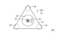
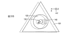
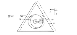
- FIG. 2 is a diagram showing the drive source 120, the rotating shaft 130, the acceleration sensor 140, and the vibration isolator 160 when cut along the line AA in FIG. 3A, 3B, and 3C are diagrams illustrating how the drive source 120, the rotation shaft 130, the acceleration sensor 140, and the vibration isolator 160 vibrate.
- the positions indicated by dotted lines in FIGS. 3A, 3B, and 3C are the original positions, and show a state where they are shifted in different directions.
- the rotor 110 includes a type having a hole for accommodating a test tube and the like, and a type in which a bucket for accommodating a tube rack for storing a sample is attached to the rotor 110.
- the type of the rotor 110 is not limited.
- the anti-vibration unit 160 plays a role of attenuating vibration caused by imbalance in the balance of the rotor 110.
- a support plate 161 holding the drive source 120 and a plurality of vibration isolation springs 162 having one end fixed to the housing 190 and the other end fixed to the support plate 161. What is necessary is just to comprise.
- the acceleration sensor 140 outputs a value indicating acceleration in two different directions perpendicular to the axial direction of the rotation axis.
- the acceleration sensor 140 may be attached to the upper surface of the drive source 120.
- the two directions are perpendicular to each other, and one is called the X-axis direction and the other is called the Y-axis direction.
- the axial direction of the rotating shaft 130 is taken as the Z-axis direction.
- a value indicating the acceleration in the X-axis direction is a X
- a value indicating the acceleration in the Y-axis direction is a Y.
- the “value indicating acceleration” includes not only a value that matches the acceleration but also a value that is proportional to the acceleration and a value that discretely indicates a value that is proportional to the acceleration, such as a digital signal.
- FIG. 4 shows an example in which a value indicating acceleration generated by vibration is measured at intervals of 5 msec when the rotor is rotated at 1000 rpm.
- the vertical axis indicates the number of bits of the digital signal that is the output of the acceleration sensor. This number of bits corresponds to the above “value indicating acceleration”.
- the negative bit number is the number of bits when the bit indicating the sign indicates negative.
- a point indicated by a square and a triangle is a measured point, and a dotted line and a two-dot chain line are lines connecting the measured points.
- the phase of the value a X indicating the acceleration in the X-axis direction is advanced by ⁇ / 2 from the phase of the value a Y indicating the acceleration in the Y-axis direction.
- the amplitude of the value indicating the acceleration is about 160. This value is a value corresponding to R ⁇ 2 in the equations (2) and (3).
- FIG. 5 shows an example in which a value indicating an acceleration generated by vibration is measured at an interval of 5 msec when the rotor is rotated at 12000 rpm.
- the vertical axis represents the absolute value of the number of bits of the digital signal that is the output of the acceleration sensor.
- the measured points are omitted, and only the lines connecting the measured points are shown.
- the value of (a X 2 + a Y 2 ) 1/2 is also indicated by a solid line.
- the acceleration caused by vibration cannot be reproduced unless it is measured at intervals of 2.5 ms or less.
- the “value corresponding to acceleration” is a value obtained by eliminating the component of time t, and even if it is not proportional to acceleration, it may be a value that increases monotonously or decreases monotonically when acceleration increases. That's fine. Details will be described in Modification 2.
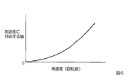
- FIG. 6 shows an image when a value corresponding to the acceleration is obtained and plotted while changing the angular velocity (number of rotations) in a centrifuge in which the balance of the rotor is unbalanced at the upper limit of the allowable range.
- the horizontal axis is angular velocity (number of rotations)
- the vertical axis is a value corresponding to acceleration.
- Figure 7 shows an example of a criterion obtained by adding the offset value to its quadratic curve quadratic curve approximates a line of FIG. 6 (b ⁇ 2 + c ⁇ + d ).
- the approximate curve is indicated by a dotted line, and the criterion is indicated by a solid line.
- the upper side of the curve indicating the determination criterion is a region that satisfies the determination criterion.
- FIG. 8 shows a processing flow of the control unit 150.
- the control unit 150 acquires values indicating accelerations in two different directions (S10).
- the control unit 150 obtains an acceleration corresponding value that is a value corresponding to acceleration in a direction perpendicular to the axial direction of the rotating shaft 130 from values indicating accelerations in two different directions (S20), and the acceleration corresponding value is determined in advance. It is confirmed whether or not the determination criterion indicating that the acceleration is large is satisfied (S30). If the determination criterion is not satisfied, the process returns to step S10. If the determination criterion is satisfied, the rotation of the rotor 110 is stopped (S40).
- the control unit 150 records constants b, c, d + offset values in advance. Then, the control unit 150 acquires values a X and a Y indicating accelerations in two different directions (S10), and (a X 2 + a Y 2 ) 1/2 is an acceleration corresponding value (the axial direction of the rotating shaft 130). (Value R ⁇ 2 ) corresponding to the acceleration in the direction perpendicular to (S20). The acceleration corresponding value (a X 2 + a Y 2 ) 1/2 is compared with the determination reference b ⁇ 2 + c ⁇ + d + offset value (S30), and when the acceleration corresponding value exceeds the determination reference, the rotation of the rotor 110 is stopped (S40). ).
- the centrifuge 100 of the first embodiment it is not necessary to determine the sampling frequency of the acceleration sensor 140 according to the sampling theorem, so that it can be set to a low frequency. Therefore, when the acceleration sensor 140 is selected, the selection can be made with an emphasis on accuracy rather than sampling at a high frequency. Therefore, regardless of the rotation speed of the rotor, the acceleration caused by the unbalance of the rotor can be accurately measured. In addition, when determining the determination criteria, it is less necessary to consider malfunctions caused by low measurement accuracy. Furthermore, since it is not necessary to increase the processing speed of the control unit 150, it is easy to use an inexpensive CPU.
- Example 1 In Example 1, two different directions are defined as an X-axis direction and a Y-axis direction perpendicular to each other. In the present invention, it is desirable to make two different directions perpendicular as in the first embodiment, but in this modification, a generalized example will be described.
- the configuration of the centrifuge is the same as in FIGS.
- Values indicating accelerations in two different directions output from the acceleration sensor 140 are a 1 and a 2 , respectively.
- the value a 1 is delayed by a phase ⁇ 1 from the value a X indicating acceleration in the X-axis direction
- the value a 2 is It is assumed that the phase a 2 is delayed from the value a X indicating the acceleration in the X-axis direction.
- a value a X indicating the acceleration in the X-axis direction is R ⁇ 2 cos ⁇ t
- a value a Y indicating the acceleration in the Y-axis direction is R ⁇ 2 sin ⁇ t.
- a 1 and a 2 can be expressed by the following equations.
- a X and a Y can be obtained as follows.
- a X ⁇ (a 1 sin ⁇ 2 ⁇ a 2 sin ⁇ 1 ) / sin ( ⁇ 1 ⁇ 2 ) (7)
- a Y (a 1 cos ⁇ 2 ⁇ a 2 cos ⁇ 1 ) / sin ( ⁇ 1 ⁇ 2 ) (8)
- the control unit 150 can obtain a value based on a X 2 + a Y 2 from the values a 1 and a 2. it can. Therefore, in the case of the first modification, the same effect as that of the first embodiment can be obtained.
- the control unit 150 uses a quartic curve (b ⁇ 4 + c ⁇ 2 + d or b ⁇ 4 + c ⁇ 3 + d ⁇ 2 + e ⁇ + f) and its quartic curve as a determination criterion, and the acceleration corresponding value exceeds the determination criterion.
- the rotation of the rotor 110 may be stopped.
- the acceleration correspondence value is a X 2 + a Y 2 itself, the calculation by the control unit 150 is simplified because the calculation of the 1/2 power is not performed as compared with the first embodiment.
- the angular velocity range may be divided into a plurality of values, and a threshold value determined for each angular velocity range may be used as the determination criterion.
- the control unit 150 may use a straight line (b ⁇ + d) and a determination reference obtained by adding an offset value to the straight line, and stop the rotation of the rotor 110 when the acceleration correspondence value exceeds the determination reference. In this case, the judgment criteria can be simplified.
- the “value corresponding to the acceleration” is a value obtained by eliminating the component of time t, and may be a value that increases monotonously or decreases monotonically when the acceleration increases. If the acceleration correspondence value is a value based on a X 2 + a Y 2 , the same effect as in the first embodiment can be obtained. However, as described above, depending on what value the value based on a X 2 + a Y 2 is set to, there are cases where the effect of reducing the amount of calculation or the effect of simplifying the judgment criteria may be obtained.
Landscapes
- Physics & Mathematics (AREA)
- General Physics & Mathematics (AREA)
- Centrifugal Separators (AREA)
Abstract
低速で回転するときに求められる処理速度を有する加速度センサと制御部を用いて、高速で回転するときにもロータのバランスの不釣り合いを原因とする加速度を精度よく測定できるようにする。本発明の遠心分離機は、ロータとロータを回転させる駆動源とロータと駆動源とを結合させる回転軸と加速度センサと制御部を備える。加速度センサは、回転軸の軸方向に垂直な2つの異なる方向の加速度を示す値を出力する。制御部は、2つの異なる方向の加速度を示す値から、回転軸の軸方向に垂直な方向の加速度に対応する値である加速度対応値を求め、当該加速度対応値があらかじめ定めた加速度が大きいことを示す判定基準を満たす場合には、ロータの回転を停止させる。
Description
本発明は、不釣り合いな状態を検知し、回転を制御する遠心分離機に関する。
試料が配置された状態のロータでは、通常、試料を含んだロータ全体の重心が回転軸上にない状態が生じる。以下では、このような状態をバランスの不釣り合いと呼ぶ。この不釣り合いが大きくなり過ぎるとロータや回転軸などが過大に振れ、遠心分離機の故障の原因となる。そして、このような不釣り合いによる振れを検出する技術として、特許文献1などが知られている。
しかしながら、従来技術では加速度センサで測定できるロータのバランスの不釣り合いを原因とする加速度は、
Rω2sinωt (1)
ただし、Rは振動の振幅(元の位置からのズレ)、ωは回転の角速度、tは時間(秒)
のように時間に依存し、周波数はω/2πである。したがって、サンプリング定理より、ω/π以上の周波数で加速度をサンプリングしなければ、振動の振幅Rを正確に求めることができない。例えば、12000rpmで回転する場合、400Hz以上(2.5m秒以下の間隔)でのサンプリングが必要となる。そのため、高速回転が可能な遠心分離機用の加速度センサには、精度が高いことよりも、まずサンプリング周波数が高いことが求められ、加速度センサの出力を処理する制御部には処理速度が速いことが求められる。一方、式(1)から分かるように加速度は角速度の二乗に比例するので、角速度が低いときには加速度は非常に小さい。したがって、角速度が低いときには十分な測定精度を得にくい。そして、十分な測定精度を得にくいことを原因として、実際にはバランスの不釣り合いが許容範囲でも角速度が低いときに停止してしまう誤動作の可能性と、許容範囲を超える不釣り合いを角速度が高くなるまで検知できない可能性がある。
本発明は、ロータの回転の速さに関わらず、ロータのバランスの不釣り合いを原因とする加速度を精度よく測定できるようにすることを目的とする。
本発明の遠心分離機は、ロータと、ロータを回転させる駆動源と、ロータと駆動源とを結合させる回転軸と、加速度センサと、制御部を備える。加速度センサは、回転軸の軸方向に垂直な2つの異なる方向の加速度を示す値を出力する。制御部は、2つの異なる方向の加速度を示す値から、回転軸の軸方向に垂直な方向の加速度に対応する値である加速度対応値を求め、当該加速度対応値があらかじめ定めた加速度が大きいことを示す判定基準を満たす場合には、ロータの回転を停止させる。
本発明の遠心分離機によれば、サンプリング周波数を考慮しなくても、回転軸の軸方向と垂直な方向の加速度に対応する値を求めることができるので、測定精度を優先して加速度センサを選定できる。よって、ロータの回転の速さに関わらず、不釣り合いを原因とする加速度を高精度に測定できる。
以下、本発明の実施の形態について、詳細に説明する。なお、同じ機能を有する構成部には同じ番号を付し、重複説明を省略する。
図1に実施例1の遠心分離機の構成例を示す。遠心分離機100は、筐体190、チャンバ192、開閉自在なチャンバ蓋191、チャンバ192内に収容されるロータ110、ロータ110を回転させる駆動源120、ロータ110と駆動源120とを結合させる回転軸130、加速度センサ140、制御部150、防振部160を備える。
図2は図1のA-A線で切ったときの駆動源120、回転軸130、加速度センサ140、防振部160を示す図である。図3A、図3B、図3Cは駆動源120、回転軸130、加速度センサ140、防振部160が振動する様子を示した図である。図3A、図3B、図3Cの点線で示した位置が元の位置であり、それぞれ異なる方向にずれた様子を示している。
ロータ110には、試験管などを収容する穴があるタイプや、試料を入れるチューブラックを収容するバケットをロータ110に取り付けるタイプなどがあるが、本発明はロータ110のタイプによらず適用できるので、ロータ110のタイプは限定しない。防振部160は、ロータ110のバランスの不釣り合いによって生じる振動を減衰させる役割を果たす。例えば、図1,2に示されたように、駆動源120を把持している支持板161と、筐体190に一端が固定され他端が支持板161に固定された複数の防振バネ162で構成すればよい。
加速度センサ140は、回転軸の軸方向に垂直な2つの異なる方向の加速度を示す値を出力する。例えば、図1,2に示されたように、加速度センサ140を駆動源120の上面に取り付ければよい。実施例1では、2つの方向は互いに垂直であり、一方をX軸方向、他方をY軸方向と呼ぶことにする。そして、回転軸130の軸方向をZ軸方向とする。また、X軸方向の加速度を示す値をaX、Y軸方向の加速度を示す値をaYとする。なお、「加速度を示す値」は、加速度と一致する値だけでなく、加速度と比例する値、およびデジタル信号のように加速度と比例する値を離散的に示した値も含んでいる。
実施例1の加速度センサ140からの出力であるaX、aYは互いに直交する方向の加速度を示す値なので、理論的には、
aY=Rω2sinωt (2)
と表現できるときには
aX=Rω2sin(ωt±π/2)=±Rω2cosωt (3)
と表現できる。なお、aXの符号は、aXの位相がaYの位相よりもπ/2進んでいる場合にプラス、遅れている場合にマイナスとなる。どちらの位相が進むかは、X軸、Y軸の正の方向の決め方と回転の方向に依存する。
aY=Rω2sinωt (2)
と表現できるときには
aX=Rω2sin(ωt±π/2)=±Rω2cosωt (3)
と表現できる。なお、aXの符号は、aXの位相がaYの位相よりもπ/2進んでいる場合にプラス、遅れている場合にマイナスとなる。どちらの位相が進むかは、X軸、Y軸の正の方向の決め方と回転の方向に依存する。
図4に、1000rpmでロータを回転させ、5m秒間隔で振動によって生じる加速度を示す値を測定した例を示す。この例では、縦軸は、加速度センサの出力であるデジタル信号のビット数で示している。このビット数が上記の「加速度を示す値」に相当する。なお、負のビット数とは符号を示すビットが負を示したときのビット数である。四角と三角で示された点が測定された点であり、点線と二点鎖線は測定された点をつないだ線である。この例では、X軸方向の加速度を示す値aXの位相がY軸方向の加速度を示す値aYの位相よりもπ/2進んでいる。図4からは、加速度を示す値の振幅は約160であることが分かる。この値は、式(2)、(3)のRω2に対応する値である。
図5に、12000rpmでロータを回転させ、5m秒間隔で振動によって生じる加速度を示す値を測定した例を示す。この例では、縦軸は、加速度センサの出力であるデジタル信号のビット数の絶対値としている。また、測定された点は省略し、測定された点をつないだ線のみを示している。図5中には、(aX
2+aY
2)1/2の値も実線で示している。12000rpmの回転の場合、2.5m秒以下の間隔で測定しなければ振動によって生じる加速度を再現できないので、点線と二点鎖線で示されたX軸方向の出力(X軸方向の加速度を示す値)の絶対値|aX|とY軸方向の出力(Y軸方向の加速度を示す値)の絶対値|aY|は、正弦波の絶対値を示す波形にはなっていない。したがって、式(2)、(3)のRω2に対応する値は、加速度を示す値aX、aYの片方だけでは求めにくい。一方、(aX
2+aY
2)1/2の値は800~1100程度で常に推移しており、式(2)、(3)のRω2に対応する値に近いと推定できる。
理論面から説明すると、式(2)、(3)から、
(aX 2+aY 2)1/2=Rω2(sin2ωt+(±cosωt)2)1/2
=Rω2 (4)
となる。つまり、回転軸に垂直な平面上の直交する2つの方向の加速度を示す値aX、aYと式(4)を用いれば、理論的には加速度Rω2に対応する値を求められる。よって、サンプリング周波数を高くし、制御部150の処理速度を速くしなくても、加速度Rω2に対応する値を求めることができる。なお、「加速度に対応する値」とは、時間tの成分が消去された値であり、加速度に比例していなくても、加速度が増加するときに単調に増加もしくは単調に減少する値であればよい。詳細については変形例2で説明する。
(aX 2+aY 2)1/2=Rω2(sin2ωt+(±cosωt)2)1/2
=Rω2 (4)
となる。つまり、回転軸に垂直な平面上の直交する2つの方向の加速度を示す値aX、aYと式(4)を用いれば、理論的には加速度Rω2に対応する値を求められる。よって、サンプリング周波数を高くし、制御部150の処理速度を速くしなくても、加速度Rω2に対応する値を求めることができる。なお、「加速度に対応する値」とは、時間tの成分が消去された値であり、加速度に比例していなくても、加速度が増加するときに単調に増加もしくは単調に減少する値であればよい。詳細については変形例2で説明する。
図6に、ロータのバランスを許容範囲の上限の不釣り合いにした遠心分離機で角速度(回転数)を変化させながら加速度に対応する値を求めてプロットしたときのイメージを示す。横軸が角速度(回転数)であり、縦軸は加速度に対応する値である。図7は、図6の線を近似した2次曲線(bω2+cω+d)とその2次曲線にオフセット値を加算した判定基準の例を示す。近似曲線を点線で、判定基準を実線で示している。判定基準を示す曲線の上側が判定基準を満たす領域である。
図8に制御部150の処理フローを示す。制御部150は、2つの異なる方向の加速度を示す値を取得する(S10)。制御部150は、2つの異なる方向の加速度を示す値から、回転軸130の軸方向に垂直な方向の加速度に対応する値である加速度対応値を求め(S20)、当該加速度対応値があらかじめ定めた加速度が大きいことを示す判定基準を満たすか確認する(S30)。判定基準を満たさない場合は、ステップS10に戻る。判定基準を満たす場合は、ロータ110の回転を停止させる(S40)。
より具体的には、実施例1では、制御部150は、あらかじめ定数b、c、d+オフセット値を記録しておく。そして、制御部150は、2つの異なる方向の加速度を示す値aX、aYを取得し(S10)、(aX
2+aY
2)1/2を加速度対応値(回転軸130の軸方向に垂直な方向の加速度に対応する値Rω2)として求める(S20)。加速度対応値(aX
2+aY
2)1/2を判定基準bω2+cω+d+オフセット値と比較し(S30)、加速度対応値が判定基準を上回ったときに、ロータ110の回転を停止させる(S40)。
実施例1の遠心分離機100によれば、加速度センサ140のサンプリング周波数をサンプリング定理にしたがって定める必要はないので、低い周波数に設定できる。したがって、加速度センサ140を選定するときに高い周波数でのサンプリングができることよりも精度を重視した選定にできる。よって、ロータの回転の速さに関わらず、ロータのバランスの不釣り合いを原因とする加速度を精度よく測定できる。また、判定基準を定める際に、測定精度が低いために生じる誤動作を考慮する必要性が低い。さらに、制御部150の処理を高速にする必要がないので安価なCPUなどを使用しやすい。
[変形例1]
実施例1では2つの異なる方向を互いに垂直なX軸方向とY軸方向とした。本発明では実施例1のように2つの異なる方向を垂直にすることが望ましいと考えるが、本変形例では一般化した例を説明する。遠心分離機の構成は、図1、2と同じである。
実施例1では2つの異なる方向を互いに垂直なX軸方向とY軸方向とした。本発明では実施例1のように2つの異なる方向を垂直にすることが望ましいと考えるが、本変形例では一般化した例を説明する。遠心分離機の構成は、図1、2と同じである。
加速度センサ140が出力する2つの異なる方向の加速度を示す値をそれぞれa1、a2とし、値a1はX軸方向の加速度を示す値aXよりも位相θ1だけ遅れ、値a2はX軸方向の加速度を示す値aXよりも位相θ2だけ遅れているとする。ここで、X軸方向の加速度を示す値aXをRω2cosωt、Y軸方向の加速度を示す値aYをRω2sinωtとする。このとき、a1、a2は次式で表現できる。
a1=Rω2cos(ωt-θ1)
=Rω2(cosωt・cosθ1+sinωt・sinθ1) (5)
a2=Rω2cos(ωt-θ2)
=Rω2(cosωt・cosθ2+sinωt・sinθ2) (6)
式(5)、(6)からaX、aYは、次のように求めることができる。
=Rω2(cosωt・cosθ1+sinωt・sinθ1) (5)
a2=Rω2cos(ωt-θ2)
=Rω2(cosωt・cosθ2+sinωt・sinθ2) (6)
式(5)、(6)からaX、aYは、次のように求めることができる。
aX=-(a1sinθ2-a2sinθ1)/sin(θ1-θ2) (7)
aY=(a1cosθ2-a2cosθ1)/sin(θ1-θ2) (8)
aY=(a1cosθ2-a2cosθ1)/sin(θ1-θ2) (8)
このように、値a1、a2からX軸方向とY軸方向の加速度を示す値aX、aYを求めれば、その後の制御部150の処理は実施例1と同じにできる。もしくは、値aX、aY自体を求めなくても(aX
2+aY
2)1/2を
(aX 2+aY 2)1/2
=((a1sinθ2-a2sinθ1)2
+(a1cosθ2-a2cosθ1)2)1/2/|sin(θ1-θ2)|(9)
のように求めてもよい。つまり、加速度センサ140は、少なくとも回転軸130の軸方向に垂直な2つの異なる方向の加速度を示す値を出力できればよい。ただし、「異なる方向」には、平行で向きが逆の方向は含まない。
(aX 2+aY 2)1/2
=((a1sinθ2-a2sinθ1)2
+(a1cosθ2-a2cosθ1)2)1/2/|sin(θ1-θ2)|(9)
のように求めてもよい。つまり、加速度センサ140は、少なくとも回転軸130の軸方向に垂直な2つの異なる方向の加速度を示す値を出力できればよい。ただし、「異なる方向」には、平行で向きが逆の方向は含まない。
このように、2つの異なる方向の加速度を示す値がaX、aYでない場合でも、制御部150は、値a1と値a2よりaX
2+aY
2に基づいた値を求めることができる。よって、変形例1の場合も実施例1と同様の効果を得ることができる。
[変形例2]
本変形例では、回転軸130の軸方向に垂直であり、かつ互いに直交する2つの方向の加速度を示す値aX、aYを求めた後の加速度対応値(回転軸130の軸方向と垂直な方向の加速度に対応する値)と判定基準の変形例を説明する。遠心分離機の構成は、図1、2と同じである。
本変形例では、回転軸130の軸方向に垂直であり、かつ互いに直交する2つの方向の加速度を示す値aX、aYを求めた後の加速度対応値(回転軸130の軸方向と垂直な方向の加速度に対応する値)と判定基準の変形例を説明する。遠心分離機の構成は、図1、2と同じである。
式(4)では、
sin2ωt+(±cosωt)2=1 (10)
となる性質を用いて時間tを消去しているので、低いサンプリング周波数でも高速回転時にも加速度に対応する値を求めることができる。したがって、加速度対応値を(aX 2+aY 2)1/2にしなくてもaX 2+aY 2に基づいた値にすれば、時間tに依存しない値にできる。「aX 2+aY 2に基づいた値」とは、aX 2+aY 2自体、aX 2+aY 2を1/2乗した値、aX 2+aY 2の定数倍などを含むが、これらには限定されない。
sin2ωt+(±cosωt)2=1 (10)
となる性質を用いて時間tを消去しているので、低いサンプリング周波数でも高速回転時にも加速度に対応する値を求めることができる。したがって、加速度対応値を(aX 2+aY 2)1/2にしなくてもaX 2+aY 2に基づいた値にすれば、時間tに依存しない値にできる。「aX 2+aY 2に基づいた値」とは、aX 2+aY 2自体、aX 2+aY 2を1/2乗した値、aX 2+aY 2の定数倍などを含むが、これらには限定されない。
例えばaX
2+aY
2を加速度対応値とした場合は、
aX 2+aY 2=R2ω4 (11)
なので、例えば、制御部150は、4次曲線(bω4+cω2+dまたはbω4+cω3+dω2+eω+f)とその4次曲線にオフセット値を加算した判定基準とし、加速度対応値が判定基準を上回ったときに、ロータ110の回転を停止させればよい。加速度対応値をaX 2+aY 2自体とすれば、実施例1と比べれば1/2乗の計算を行わないので制御部150の処理は簡単になる。また、判定基準を曲線にしなくても、角速度の範囲を複数に分割し、角速度の範囲ごとに定めた閾値を判定基準としてもよい。
aX 2+aY 2=R2ω4 (11)
なので、例えば、制御部150は、4次曲線(bω4+cω2+dまたはbω4+cω3+dω2+eω+f)とその4次曲線にオフセット値を加算した判定基準とし、加速度対応値が判定基準を上回ったときに、ロータ110の回転を停止させればよい。加速度対応値をaX 2+aY 2自体とすれば、実施例1と比べれば1/2乗の計算を行わないので制御部150の処理は簡単になる。また、判定基準を曲線にしなくても、角速度の範囲を複数に分割し、角速度の範囲ごとに定めた閾値を判定基準としてもよい。
また、例えばaX
2+aY
2を1/4乗した値を加速度対応値とした場合は、
(aX 2+aY 2)1/4=R1/2ω (12)
なので、例えば、制御部150は、直線(bω+d)とその直線にオフセット値を加算した判定基準とし、加速度対応値が判定基準を上回ったときに、ロータ110の回転を停止させてもよい。この場合は、判断基準を簡単にできる。
(aX 2+aY 2)1/4=R1/2ω (12)
なので、例えば、制御部150は、直線(bω+d)とその直線にオフセット値を加算した判定基準とし、加速度対応値が判定基準を上回ったときに、ロータ110の回転を停止させてもよい。この場合は、判断基準を簡単にできる。
このように、「加速度に対応する値」は、時間tの成分が消去された値であり、加速度が増加するときに単調に増加もしくは単調に減少する値であればよい。そして、加速度対応値をaX
2+aY
2に基づいた値とすれば、実施例1と同様の効果を得ることができる。ただし、上述のようにaX
2+aY
2に基づいた値をどのような値にするかで、計算量を削減する効果や判断基準を簡素化できる効果などを得られる場合がある。
100 遠心分離機 110 ロータ
120 駆動源 130 回転軸
140 加速度センサ 150 制御部
160 防振部 161 支持板
162 防振バネ 190 筐体
191 チャンバ蓋 192 チャンバ
120 駆動源 130 回転軸
140 加速度センサ 150 制御部
160 防振部 161 支持板
162 防振バネ 190 筐体
191 チャンバ蓋 192 チャンバ
Claims (6)
- ロータと前記ロータを回転させる駆動源と前記ロータと前記駆動源とを結合させる回転軸とを備える遠心分離機であって、
前記回転軸の軸方向に垂直な2つの異なる方向の加速度を示す値を出力する加速度センサと、
前記2つの異なる方向の加速度を示す値から、前記回転軸の軸方向に垂直な方向の加速度に対応する値である加速度対応値を求め、当該加速度対応値があらかじめ定めた加速度が大きいことを示す判定基準を満たす場合には、前記ロータの回転を停止させる制御部
を備える遠心分離機。 - 請求項1記載の遠心分離機であって、
前記2つの異なる方向の加速度を示す値をそれぞれa1、a2とし、
前記回転軸の軸方向に垂直であり、かつ互いに直交する2つの方向の加速度を示す値をそれぞれaX、aYとし、
前記制御部は、値a1と値a2より、前記加速度対応値を、
aX 2+aY 2
に基づいた値となるように求める
ことを特徴とする遠心分離機。 - 請求項1記載の遠心分離機であって、
前記2つの異なる方向は、互いに垂直な方向である
ことを特徴とする遠心分離機。 - 請求項3記載の遠心分離機であって、
前記2つの異なる方向の加速度を示す値をそれぞれaX、aYとするときに、前記加速度対応値を、
aX 2+aY 2
に基づいた値とする
ことを特徴とする遠心分離機。 - 請求項2または4記載の遠心分離機であって、
前記加速度対応値を
(aX 2+aY 2)1/2
に比例した値とする
ことを特徴とする遠心分離機。 - 請求項5記載の遠心分離機であって、
前記判定基準は、前記回転軸の角速度の2次関数で表現される基準を、前記加速度対応値が上回ったときに満たすと判定される
ことを特徴とする遠心分離機。
Priority Applications (3)
| Application Number | Priority Date | Filing Date | Title |
|---|---|---|---|
| US15/772,647 US10919050B2 (en) | 2015-11-16 | 2016-07-26 | Centrifuge that obtains an acceleration value and controls rotation |
| CN201680065773.5A CN108348930B (zh) | 2015-11-16 | 2016-07-26 | 离心分离机 |
| EP16865968.8A EP3378566B1 (en) | 2015-11-16 | 2016-07-26 | Centrifuge |
Applications Claiming Priority (2)
| Application Number | Priority Date | Filing Date | Title |
|---|---|---|---|
| JP2015223610A JP6640536B2 (ja) | 2015-11-16 | 2015-11-16 | 遠心分離機 |
| JP2015-223610 | 2015-11-16 |
Publications (1)
| Publication Number | Publication Date |
|---|---|
| WO2017085965A1 true WO2017085965A1 (ja) | 2017-05-26 |
Family
ID=58718657
Family Applications (1)
| Application Number | Title | Priority Date | Filing Date |
|---|---|---|---|
| PCT/JP2016/071827 Ceased WO2017085965A1 (ja) | 2015-11-16 | 2016-07-26 | 遠心分離機 |
Country Status (5)
| Country | Link |
|---|---|
| US (1) | US10919050B2 (ja) |
| EP (1) | EP3378566B1 (ja) |
| JP (1) | JP6640536B2 (ja) |
| CN (1) | CN108348930B (ja) |
| WO (1) | WO2017085965A1 (ja) |
Cited By (1)
| Publication number | Priority date | Publication date | Assignee | Title |
|---|---|---|---|---|
| US20200384483A1 (en) * | 2018-01-25 | 2020-12-10 | Kubota Manufacturing Corporation | Centrifuge |
Families Citing this family (5)
| Publication number | Priority date | Publication date | Assignee | Title |
|---|---|---|---|---|
| DE102014116527B4 (de) * | 2014-11-12 | 2020-01-23 | Andreas Hettich Gmbh & Co. Kg | Zentrifuge und Verfahren zur Erfassung von Unwuchten in der Zentrifuge |
| CN111881525B (zh) * | 2020-07-17 | 2022-05-17 | 浙江大学 | 基于动力模态的超重力离心机安全运行控制与提高方法 |
| US12280382B2 (en) * | 2021-06-24 | 2025-04-22 | Elgin Separation Solutions Industrials, Llc | Electronically controlled hydraulic decanter centrifuge |
| CN114534933A (zh) * | 2022-01-17 | 2022-05-27 | 黄小燕 | 一种生物药品制造溶解用新型离心机 |
| CN114705232B (zh) * | 2022-03-16 | 2024-06-04 | 南京苏试广博环境可靠性实验室有限公司 | 一种单片机红外光电测转速系统 |
Citations (5)
| Publication number | Priority date | Publication date | Assignee | Title |
|---|---|---|---|---|
| JP2002306989A (ja) | 2001-04-13 | 2002-10-22 | Hitachi Koki Co Ltd | 遠心機のインバランス検出装置 |
| US20050007046A1 (en) * | 2003-07-09 | 2005-01-13 | Kendro Laboratory Products, Lp | Rotor speed control device and method |
| JP2005111402A (ja) * | 2003-10-09 | 2005-04-28 | Hitachi Koki Co Ltd | 遠心機 |
| JP2009039630A (ja) * | 2007-08-08 | 2009-02-26 | Olympus Corp | 遠心分離機および遠心分離機を用いた細胞処理装置 |
| JP2015136689A (ja) * | 2014-01-24 | 2015-07-30 | 株式会社写真化学 | 攪拌・脱泡装置 |
Family Cites Families (9)
| Publication number | Priority date | Publication date | Assignee | Title |
|---|---|---|---|---|
| JPS60154134A (ja) * | 1984-01-23 | 1985-08-13 | Shimadzu Corp | 動つりあい試験機 |
| JP2007090325A (ja) * | 2005-09-01 | 2007-04-12 | Hitachi Koki Co Ltd | 遠心分離機 |
| DE102007042488A1 (de) * | 2007-09-06 | 2009-03-12 | Schaeffler Kg | Separator mit wenigstens einem magnetorheologischen oder elektrorheologischen Dämpfer |
| CN101173878B (zh) * | 2007-11-27 | 2010-06-02 | 上海西派埃自动化仪表工程有限责任公司 | 静、动态加速度测试装置 |
| JP2011173043A (ja) * | 2010-02-23 | 2011-09-08 | Olympus Corp | 遠心分離機および細胞処理装置 |
| WO2012160025A1 (de) | 2011-05-23 | 2012-11-29 | Amst-Systemtechnik Gmbh | Vorrichtung und verfahren zur simulation von beschleunigungen |
| CN203396545U (zh) * | 2013-07-10 | 2014-01-15 | 长沙高新开发区天骄电子有限公司 | 非接触式不平衡检测装置 |
| DE102014116527B4 (de) * | 2014-11-12 | 2020-01-23 | Andreas Hettich Gmbh & Co. Kg | Zentrifuge und Verfahren zur Erfassung von Unwuchten in der Zentrifuge |
| CN104457965A (zh) * | 2014-11-21 | 2015-03-25 | 广西智通节能环保科技有限公司 | 一种振动检测报警装置 |
-
2015
- 2015-11-16 JP JP2015223610A patent/JP6640536B2/ja active Active
-
2016
- 2016-07-26 CN CN201680065773.5A patent/CN108348930B/zh active Active
- 2016-07-26 US US15/772,647 patent/US10919050B2/en active Active
- 2016-07-26 EP EP16865968.8A patent/EP3378566B1/en active Active
- 2016-07-26 WO PCT/JP2016/071827 patent/WO2017085965A1/ja not_active Ceased
Patent Citations (5)
| Publication number | Priority date | Publication date | Assignee | Title |
|---|---|---|---|---|
| JP2002306989A (ja) | 2001-04-13 | 2002-10-22 | Hitachi Koki Co Ltd | 遠心機のインバランス検出装置 |
| US20050007046A1 (en) * | 2003-07-09 | 2005-01-13 | Kendro Laboratory Products, Lp | Rotor speed control device and method |
| JP2005111402A (ja) * | 2003-10-09 | 2005-04-28 | Hitachi Koki Co Ltd | 遠心機 |
| JP2009039630A (ja) * | 2007-08-08 | 2009-02-26 | Olympus Corp | 遠心分離機および遠心分離機を用いた細胞処理装置 |
| JP2015136689A (ja) * | 2014-01-24 | 2015-07-30 | 株式会社写真化学 | 攪拌・脱泡装置 |
Non-Patent Citations (1)
| Title |
|---|
| See also references of EP3378566A4 * |
Cited By (2)
| Publication number | Priority date | Publication date | Assignee | Title |
|---|---|---|---|---|
| US20200384483A1 (en) * | 2018-01-25 | 2020-12-10 | Kubota Manufacturing Corporation | Centrifuge |
| US11958063B2 (en) * | 2018-01-25 | 2024-04-16 | Kubota Manufacturing Corporation | Centrifuge having control unit that stops rotation of a rotor when a displacement-conversion value satisifies a displacement determination criterion |
Also Published As
| Publication number | Publication date |
|---|---|
| JP6640536B2 (ja) | 2020-02-05 |
| EP3378566B1 (en) | 2020-06-17 |
| EP3378566A4 (en) | 2019-08-28 |
| US10919050B2 (en) | 2021-02-16 |
| CN108348930B (zh) | 2020-03-27 |
| US20190134646A1 (en) | 2019-05-09 |
| JP2017087178A (ja) | 2017-05-25 |
| CN108348930A (zh) | 2018-07-31 |
| EP3378566A1 (en) | 2018-09-26 |
Similar Documents
| Publication | Publication Date | Title |
|---|---|---|
| WO2017085965A1 (ja) | 遠心分離機 | |
| TWI652448B (zh) | 轉速感測器及其操作方法 | |
| CN101896659A (zh) | 具有用于感测由于洗衣滚筒组件的动态不平衡引起的洗衣组件的运动的电子设备的洗衣机和相关操作方法 | |
| JP2012173055A5 (ja) | ||
| CN102175394B (zh) | 刚性转子软支承动不平衡测试中的永久标定方法 | |
| EP2667155B1 (fr) | Centrale inertielle à gyroscopes vibrants montés sur un carrousel et procédé de mesure angulaire | |
| JP5028281B2 (ja) | センサバイアスキャンセルを用いた慣性計測システム及び方法 | |
| CN105478245B (zh) | 基于主轴振动检测的双自由度精密离心机副轴动不平衡量辨识方法 | |
| EP2926088B1 (fr) | Procede de calibration d'une centrale inertielle a plage de retournement mecanique limitee | |
| WO2015145489A1 (ja) | 加速度センサ、および加速度または振動検出方法 | |
| JP2012047707A (ja) | 振動検出装置、振動抑制装置、および、振動情報表示装置 | |
| WO2012165442A1 (ja) | タイヤバランス試験方法及びタイヤバランス試験機 | |
| US11958063B2 (en) | Centrifuge having control unit that stops rotation of a rotor when a displacement-conversion value satisifies a displacement determination criterion | |
| JP6371667B2 (ja) | 回転アンバランス測定装置 | |
| JP6370239B2 (ja) | 回転体の動的不釣り合いの測定方法並びにその測定装置 | |
| CN203705121U (zh) | 一种车轮动平衡机用一体化轴系 | |
| Konopiński et al. | Two planes balancing method of UAV motors using a single three-axis MEMS accelerometer | |
| JP6273647B2 (ja) | 加速度センサ特性評価装置及び方法 | |
| TWI702374B (zh) | 具有在多頻操作時有多種估算的轉速感應器及操作轉速感應器的方法 | |
| JPH04168314A (ja) | 移動体の傾斜角度計測装置 | |
| KR20180045692A (ko) | 회전체 불평형 제거 장치 및 방법 | |
| Neumeuer et al. | Application of Goertzel Algorithm for unbalance signal processing | |
| CN109510377A (zh) | 一种防抖动的电机 | |
| Yoshida et al. | Motion Analysis of Balancing Balls of Auto-Balancer for Reducing Error in Passing Critical Speed | |
| JPS61204530A (ja) | 回転体の高速釣り合せ装置 |
Legal Events
| Date | Code | Title | Description |
|---|---|---|---|
| 121 | Ep: the epo has been informed by wipo that ep was designated in this application |
Ref document number: 16865968 Country of ref document: EP Kind code of ref document: A1 |
|
| NENP | Non-entry into the national phase |
Ref country code: DE |
|
| WWE | Wipo information: entry into national phase |
Ref document number: 2016865968 Country of ref document: EP |