WO2017086256A1 - スクイズ容器 - Google Patents
スクイズ容器 Download PDFInfo
- Publication number
- WO2017086256A1 WO2017086256A1 PCT/JP2016/083586 JP2016083586W WO2017086256A1 WO 2017086256 A1 WO2017086256 A1 WO 2017086256A1 JP 2016083586 W JP2016083586 W JP 2016083586W WO 2017086256 A1 WO2017086256 A1 WO 2017086256A1
- Authority
- WO
- WIPO (PCT)
- Prior art keywords
- pair
- shoulder
- squeeze container
- tapered
- trunk
- Prior art date
- Legal status (The legal status is an assumption and is not a legal conclusion. Google has not performed a legal analysis and makes no representation as to the accuracy of the status listed.)
- Ceased
Links
Images



Classifications
-
- B—PERFORMING OPERATIONS; TRANSPORTING
- B65—CONVEYING; PACKING; STORING; HANDLING THIN OR FILAMENTARY MATERIAL
- B65D—CONTAINERS FOR STORAGE OR TRANSPORT OF ARTICLES OR MATERIALS, e.g. BAGS, BARRELS, BOTTLES, BOXES, CANS, CARTONS, CRATES, DRUMS, JARS, TANKS, HOPPERS, FORWARDING CONTAINERS; ACCESSORIES, CLOSURES, OR FITTINGS THEREFOR; PACKAGING ELEMENTS; PACKAGES
- B65D1/00—Rigid or semi-rigid containers having bodies formed in one piece, e.g. by casting metallic material, by moulding plastics, by blowing vitreous material, by throwing ceramic material, by moulding pulped fibrous material or by deep-drawing operations performed on sheet material
- B65D1/32—Containers adapted to be temporarily deformed by external pressure to expel contents
-
- B—PERFORMING OPERATIONS; TRANSPORTING
- B65—CONVEYING; PACKING; STORING; HANDLING THIN OR FILAMENTARY MATERIAL
- B65D—CONTAINERS FOR STORAGE OR TRANSPORT OF ARTICLES OR MATERIALS, e.g. BAGS, BARRELS, BOTTLES, BOXES, CANS, CARTONS, CRATES, DRUMS, JARS, TANKS, HOPPERS, FORWARDING CONTAINERS; ACCESSORIES, CLOSURES, OR FITTINGS THEREFOR; PACKAGING ELEMENTS; PACKAGES
- B65D35/00—Pliable tubular containers adapted to be permanently or temporarily deformed to expel contents, e.g. collapsible tubes for toothpaste or other plastic or semi-liquid material; Holders therefor
- B65D35/02—Body construction
Definitions
- This invention relates to a squeeze container that discharges contents by a compression operation.
- the contents are usually discharged by compressing the body part, but by simply compressing only the body part, the corner formed between the shoulder part and the body part is finally obtained. There arises a problem that a large amount of contents remain in the corners.
- the vicinity of the shoulder is greatly compressed and deformed, specifically, the inner surface of the shoulder and the inner surface of the torso are folded or crushed. It is necessary to do.
- the shoulder is often formed thick, and a large force is required to compress and deform the vicinity of the shoulder.
- Patent Document 1 a crease is provided in the vicinity of the shoulder so that the vicinity of the shoulder can be compressed and deformed with a small force.
- the shoulder area may be deformed up to the neck, and if functional parts such as nozzles and check valves are separately attached to the neck, the parts may come off or unintentionally. Various problems such as leakage of contents from the portion may occur.
- an object of the present invention is to provide a squeeze container capable of suppressing the remaining contents without greatly compressing and deforming the vicinity of the shoulder.
- the squeeze container according to the present invention is provided with an open cylindrical neck, a shoulder extending substantially horizontally from the base end of the neck, a trunk provided below the shoulder, and a lower part of the trunk.
- a squeeze container that discharges contents by compressing the body part back and forth from the outside, and the shape of the body part in a plan view is a polygon that tapers in the left-right direction or
- the body part is a pair of front and rear pressing parts disposed so as to oppose each other so that the polygon or the ellipse is flattened in the left-right direction by compressing back and forth, and the left and right connecting them.
- the V-shaped grooves are formed so as to face each other.
- the shoulder portion has a pair of front and rear main shoulder edges facing the pair of front and rear pressing portions, and a pair of left and right side shoulder edges connecting both ends thereof, and the main shoulder edge of the shoulder portion
- a pair of front and rear V-shaped grooves are provided between the pressing portion of the body portion and the trunk portion, and a taper toward the lower outer side is provided between the side shoulder edge of the shoulder portion and the tapered portion of the body portion.
- a pair of right and left inclined portions are provided, and the inclined portion has a shape that tapers from the side shoulder edge toward the end of the tapered portion, and the upper bending line is the inclined portion. It is preferable to extend to the taper apex of the part or the vicinity thereof.
- the pair of front and rear is configured such that the bottom portion extends substantially horizontally, and is recessed in the direction of the central axis of the body portion between each pressing portion and the bottom portion of the body portion, and a downward bending line extending substantially horizontally is a groove bottom.
- the second V-shaped grooves are preferably formed so as to face each other.
- the bottom portion has a pair of front and rear main bottom edges facing the pair of front and rear pressing portions, and a pair of left and right side bottom edges connecting both ends thereof.
- a pair of front and rear second V-shaped grooves are provided between the pressing portion of the portion, and between the side bottom edge of the bottom portion and the tapered portion of the trunk portion, the second V-shaped groove is tapered toward the upper outer side.
- the shape of the second inclined portion is provided in a pair of left and right, the second inclined portion has a shape that tapers from the side bottom edge toward the end of the tapered portion, and the downward bending line is It is preferable that the second inclined portion extends to a tapered apex or the vicinity thereof.
- a leg portion extending downward is provided at the bottom portion.
- a droplet nozzle is provided at the neck.
- the body is not restored after being compressed.
- the neck is provided with a check valve that allows a flow from the inside to the outside and blocks the flow from the outside to the inside, or is formed of a material that is plastically deformed. .
- the neck portion is composed of a cylindrical neck portion main body and a constricted portion having a reduced diameter below the neck portion.
- the internal space is filled with about 15 to about 85% of the full amount of medicine.
- the V-shaped groove is formed between the pressing portion of the trunk portion and the shoulder portion, the angle of the corner portion formed by the shoulder portion and the trunk portion is a general squeeze. It is smaller than the container, and the space formed in the corner is smaller. Therefore, the amount of contents located at the corner can be reduced from the beginning. Further, since the upper bent line of the V-shaped groove is naturally deformed toward the shoulder inner surface in accordance with the compression operation for flattening the body portion, the space generated in the corner portion can be further reduced. Can be suppressed. Furthermore, since the shoulder portion and the pressing portion of the trunk portion are separated by the V-shaped groove, the influence of the compression operation hardly reaches the shoulder portion, and deformation of the neck portion can be suppressed. Furthermore, since the rigidity with respect to the compression from the left-right direction is ensured by the pair of V-shaped grooves, it is possible to suppress excessive discharge of the contents due to the compression from the left-right direction.
- the upper bending line extends to the tapered apex of the inclined portion or the vicinity thereof, even if an unexpected external force acts on the inclined portion, such as dropping the squeeze container, the pair of V-shaped grooves becomes a resistance. Therefore, the excessive discharge of the contents can be suppressed. Further, since the inclined portion is deformed so as to expand in the left-right direction due to the compression of the pressing portion, the flattened body portion can be drawn toward the shoulder portion, and the space generated in the corner portion can be further reduced.
- V-shaped grooves are formed between the press part and bottom part of a trunk
- the downward bending line extends to the tapered apex of the second inclined portion or the vicinity thereof, even if a pushing force is applied to the second inclined portion, the second V-shaped groove becomes a resistance and deformation is suppressed. Therefore, excessive discharge of contents can be suppressed.
- the container can be made independent.
- the contents can be dropped one by one.
- the body after the body is compressed, it is configured not to be restored. Specifically, if a check valve is provided, invasion of bacteria and the like can be suppressed, and the squeeze container is plastically deformed. If it is made of a material, it is easy to deform and the contents can be easily discharged. In any case, the flattening of the container by the compression operation can be promoted.
- the neck is composed of a neck body and a constricted portion, the strength of the neck can be improved and deformation of the neck can be suppressed.
- the container when filling the internal space with the drug, if the amount of the drug is kept at about 15 to about 85% of the full volume, and the rest is made a gas such as an inert gas, the container is completely compressed and deformed. All the contents can be pushed out without letting it go.
- a squeeze container provided with a droplet nozzle is preferable because the container is used upside down.
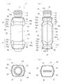
- An embodiment of the squeeze container of this invention is shown, (a) is a front view, (b) is a side view, (c) is a plan view, and (d) is a bottom view. It is a front view which shows the cap attached to a squeeze container, a droplet nozzle, and a non-return valve.
- the compression deformation of a squeeze container is shown, (a) is a schematic side view, (b) is a schematic front view.
- the other embodiment of the squeeze container of this invention is shown, (a) is a front view, (b) is a side view, (c) is a top view, (d) is a bottom view.
- the other embodiment of the squeeze container of this invention is shown, (a) is a front view, (b) is a side view, (c) is a top view, (d) is a bottom view.
- the other embodiment of the squeeze container of this invention is shown, (a) is a front view, (b) is a side view.
- the squeeze container 1 includes an open cylindrical neck portion 10, a shoulder portion 20 extending substantially horizontally from the base end of the neck portion 10, and a trunk portion provided below the shoulder portion 20. 30 and a bottom portion 40 provided below the trunk portion 30.
- the neck portion 10 has an opening 11 for discharging the contents. As shown in FIGS. 1a and 1b, the neck portion main body 12 and a constricted portion (contracted) formed below the neck portion main body 12 are provided. (Diameter portion) 13. A screw 12 a for attaching a cap C that closes the opening 11 is formed on the outer peripheral surface of the neck body 12. As shown in FIG. 2, in addition to the cap C, the neck 10 has a droplet nozzle N that can drop the contents one by one, and a reverse for preventing the entry of substances from outside air into the container. Functional parts such as a stop valve V are appropriately attached. The constricted portion 13 is for improving the strength of the neck portion 10 and suppressing deformation of the neck portion 10.
- the shoulder portion 20 extends from the lower end of the constricted portion 13 of the neck portion 10, and is substantially rectangular in plan view as shown in FIG. 1c.
- the shoulder portion 20 is thicker than the trunk portion 30, and the rigidity in the front-rear and left-right directions is ensured.
- two sides parallel to each other among the four sides constituting the substantially quadrilateral face the pressing portion 31 of the trunk portion 30 described later, that is, they are arranged corresponding to (in a line with) the vertical direction.
- two sides facing the pressing portion 31 are referred to as a main shoulder edge 21, and two sides connecting both ends of the main shoulder edge 21 are referred to as a side shoulder edge 22.
- the body 30 is a substantially oval shape (spindle shape) in a plan view that tapers in the left-right direction, and has a tubular shape that is long in the up-down direction as a whole. In this embodiment, it gradually spreads downward in a front view and narrows downward in a side view. However, it may be straight.
- the body portion 30 is compressed back and forth so that the inner surfaces are in close contact with each other, whereby a pair of front and rear pressing portions 31 and 31 disposed so as to face each other so that a substantially oval shape in plan view is flattened in the left and right direction, It has a pair of left and right tapered portions 32, 32 connecting the pressing portions 31, 31.
- the upper bending line 51 continuous in the circumferential direction toward a substantially horizontal direction is formed.
- the upper bent line 51 is recessed in the direction of the central axis of the body portion 30, and forms a V-shaped groove 50 with the panel portion 52 positioned above and below the upper bent line 51.
- the panel portion 52 includes a first panel portion 52 a formed between the main shoulder edge 21 of the shoulder portion 20 and the upper bending line 51, the upper bending line 51, and the body portion 30. Between the second pressing portion 31, that is, between the second panel portion 52 b formed below the first panel portion 52 a, and between the side shoulder edge 22 of the shoulder portion 20 and the upper bending line 51, that is, the first panel portion 52 a. And a fourth panel portion 52d formed between the upper bent line 51 and the tapered portion 32 of the trunk portion 30, that is, below the third panel portion 52c. As shown in FIG.
- the first panel portion 52 a has a vertical length (length from the main shoulder edge 21 of the shoulder portion 20 to the upper bending line 51) L1 of the side shoulder edge 22 of the shoulder portion 20. It is shorter than half of the length L2.
- the third panel portion 52c has a substantially triangular shape in a side view, and the inclined portion 60 is located above the third panel portion 52c.
- the vicinity of the ridge line part of each panel part 52a, 52b, 52c, 52d and the four corner corner part of the shoulder part 20 is not restricted to a square shape, and may be a slightly rounded shape.
- each panel part 52a, 52b, 52c, 52d may be smoothly curved outward or inward of the container.
- the portion in contact with the upper bending line 51 is preferably not curved from the viewpoint of ensuring the rigidity in the left-right direction by the pair of V-shaped grooves 50, 50.
- the inclined portion 60 connects the side shoulder edge 22 of the shoulder portion 20 and the upper sides of the third panel portions 52c provided in a pair of left and right sides in side view, as shown in FIG. 1b.
- the shape is tapered toward the lower outer side, specifically a substantially triangular shape.
- the inclined portion 60 tapers from the side shoulder edge 22 toward the end of the tapered portion 32.
- the upper bending line 51 is extended (connected) to this tapered vertex 60a. Note that the vertex 60 a does not necessarily need to be connected to the upper bending line 51 as long as it is located in the vicinity of the upper bending line 51.
- the broken line 60b is provided in the up-down direction in the center part of the inclination part 60, this broken line may be a little rounded. Further, the inclined portion 60 may be smoothly curved outward or inward of the container without providing the broken line 60b, or may be flat.
- the bottom 40 has a single character shape as shown in FIG. 1d. This is formed by pinching off the lower end of the tubular body 30.
- the squeeze container 1 having the above-described configuration is manufactured, for example, by blow molding a flexible polyethylene resin.
- the container is filled with a liquid medicine such as eye drops as the contents.
- the content fill is about 15 to about 85% of the full volume (usually about 2 to about 6 mL for a full volume about 7 to about 12 mL container).
- a space other than the contents inside the container may be filled with an inert gas in order to prevent the contents from being altered.
- a droplet nozzle N for discharging the contents one by one to the neck 10 a check valve V and a nozzle for preventing intrusion of substances from outside air into the container
- a cap C or the like for protecting N is appropriately attached.
- the pressing part 31 of the trunk part 30 When discharging the contents from the squeeze container 1, the pressing part 31 of the trunk part 30 is compressed back and forth.
- the check valve V When the check valve V is attached to the neck portion 10, the pressing portion 31 of the trunk portion 30 is deformed so as to be greatly recessed in the front-rear direction as the contents are discharged. Since the pressing part 31 of the part 30 is separated, the influence of the compression operation of the body part 30 hardly reaches the shoulder part 20, and the deformation of the neck part 10 due to the compression operation is suppressed. For this reason, it is possible to suppress the occurrence of problems such as the droplet nozzle N being detached or the check valve V not functioning.
- the upper bending lines 51 and 51 are also moved in a direction approaching each other, but the upper portion of the first panel portion 52a is the shoulder portion 20. Therefore, the upward bending line 51 moves toward the shoulder portion 20 with the main shoulder edge 21 as the center of rotation. Therefore, as shown in FIG. 3a, the space generated in the corner between the shoulder 20 and the first panel 52a is reduced (the angle of the corner is reduced), and the contents located in the corner Is naturally suppressed.
- This effect is further prominent because the upper bending line 51 is continuous in the circumferential direction and the apex 60a of the inclined portion 60 and the upper bending line 51 intersect or are close to each other. That is, as shown in FIG.
- dropping the squeeze container 1 or making a mistake in the compression operation may compress the inclined portion 60 and the tapered portion 32 of the trunk portion 30 from the left and right directions.
- the apex 60 a of the inclined portion 60 moves in the direction of the central axis of the trunk portion 30, and the entire trunk portion 30 is separated from the shoulder portion 20.
- the V-shaped groove 50 is deformed so as to reduce the groove depth, and the space generated in the corner portion between the shoulder portion 20 and the first panel portion 52a is increased (the corner portion). Increase the angle). Therefore, the excessive discharge of the contents is suppressed despite the compression.
- the space between the shoulder portion 20 and the trunk portion 30 is reduced from the beginning by the V-shaped groove 50, and the amount of contents located in the vicinity of the shoulder portion 20 is general. Less than a squeeze container. Therefore, it is not always necessary to greatly deform the vicinity of the shoulder portion 20 as long as a certain amount of contents remain.
- an inverted state the neck portion 10 is directed downward
- the contents are always located at the neck portion 10 even if the container is not completely compressed. If it is used in the state), it is possible to discharge all the contents.
- FIG. 4 shows a squeeze container 1a which is a modification of the squeeze container 1 shown in FIG.
- the difference from the squeeze container 1 of FIG. 1 is that the pressing portion 31 of the trunk portion 30 is provided with a flat portion 31a.
- the flat surface portion 31a is formed by flattening the top in the short axis direction of the body portion 30 that is oblong in plan view so as to be substantially parallel to the long axis direction. Therefore, as shown in FIGS. 4 c and 4 d, the planar shape of the body portion 30 is a shape (flat oblong shape, saddle shape, oval shape) in which the top portion in the minor axis direction of the ellipse is cut out. Further, as shown in FIG.
- the flat portion 31a is provided such that the upper portion thereof protrudes toward the second panel 52b, so that the ridge line portion of the lower end portion of the second panel 52b is slightly different from FIG. Is different.
- Other configurations are almost the same as those in FIG. 1, and thus the same reference numerals are given and detailed description is omitted.
- Providing the flat surface portion 31a in this manner makes it easier to attach a finger and thus makes it easier to hold the container. Moreover, it becomes easy to compress a container (it becomes easy to crush), and it becomes easy to crush a container equally. In the squeeze container 1a, the container internal pressure may be reduced to fill the contents. Thereby, the check function of the check valve V can be assisted.
- the container when the inside of the container is depressurized, the container may be irregularly dented and the appearance may be deteriorated.
- the flat portion 31a is mainly deformed so as to bend inward, so that deformation of other portions It is possible to suppress the dent deformation of the container due to the negative pressure in the container.
- FIG. 5 shows a squeeze container 2 according to another embodiment of the present invention.
- drum 30 in planar view is made into the hexagon which makes a tapering shape in the left-right direction, as shown in FIG. 5c. 5a and 5b, the bottom 40 extends substantially horizontally, the bottom 40 and the shoulder 20 have substantially the same shape in plan view, and the body 30 is formed straight.
- a V-shaped groove (second V-shaped groove) 70 is also formed between the bottom portion 40 and the pressing portion 31 of the body portion 30. In this respect, it is greatly different from the previous embodiment. Therefore, this difference will be particularly described.
- the bottom 40 has a substantially rectangular shape in plan view as shown in FIG. 5d.
- two sides parallel to each other among the four sides constituting the substantially quadrilateral face the pressing portion 31 of the body portion 30.
- two sides facing the pressing portion 31 are referred to as a main bottom edge 41
- two sides connecting both ends of the main bottom edge 41 are referred to as a side bottom edge 42.
- the second V-shaped groove 70 is formed between the trunk portion 30 and the bottom portion 40. As shown in FIGS. 5a and 5b, the second V-shaped groove 70 is recessed in the central axis direction of the body portion 30 and has a downward bending line 71 continuous in the circumferential direction in a substantially horizontal direction as a groove bottom. It is formed by the panel part 72 located above and below the bending line 71.
- the panel portion 72 includes a fifth panel portion 72 a formed between the main bottom edge 41 of the bottom portion 40 and the downward bending line 71, the downward bending line 71, and the body portion 30.
- the pressing portion 31 that is, the sixth panel portion 72b formed above the fifth panel portion 72a
- the side bottom edge 42 of the bottom portion 40 and the downward bending line 71 that is, left and right of the fifth panel portion 72a.
- the seventh panel portion 72c is formed between the lower bent line 71 and the tapered portion 32 of the body portion 30, that is, the eighth panel portion 72d formed above the seventh panel portion 72c.
- the fifth panel portion 72a is formed such that the vertical length (the length from the main bottom edge 41 of the bottom portion 40 to the downward bending line 71) L4 is shorter than half the length L5 of the side bottom edge 42 of the bottom portion 40.
- the seventh panel portion 72c is substantially triangular in a side view, and the second inclined portion 80 is positioned below the seventh panel portion 72c.
- the vicinity of the ridge line part of each panel part 72a, 72b, 72c, 72d and the four corner corner part of the bottom part 40 is not restricted to a square shape, and may be a slightly rounded shape.
- the second inclined portion 80 connects the side bottom edge 42 of the bottom portion 40 and the respective lower sides of the seventh panel portion 72c provided in a pair of left and right sides when viewed from the side. It has a tapered shape, specifically a substantially triangular shape.
- the second inclined portion 80 tapers from the side bottom edge 42 toward the end of the tapered portion 32.
- a downward bending line 71 extends (connects) to the tapered vertex 80a.
- a V-shaped groove is also formed between the trunk portion 30 and the bottom portion 40, the content can be prevented from remaining on the bottom portion 40 side.
- the V-shaped grooves are formed on the upper and lower sides, and the appearance is good.
- the bottom 40 is substantially horizontal, that is, substantially flat, a leg 43 that extends downward can be provided on the bottom 40. In this case, the container can be made independent.
- the present invention is not limited to the above-described embodiments, and various modifications can be made within the scope of the present invention.
- the material of the squeeze containers 1, 1a, 2, 2a is not limited to polyethylene resin, and various flexible synthetic resins can be used. A metal plate or a laminate of a metal foil and a resin can also be used. If a plastically deformable material is used, the inflow of a substance from outside air into the container can be suppressed without providing the check valve V.
- drum 30 is not restricted to an ellipse or a hexagon, It is good also as polygons, such as a rectangle and an octagon.
Landscapes
- Engineering & Computer Science (AREA)
- Mechanical Engineering (AREA)
- Ceramic Engineering (AREA)
- Containers Having Bodies Formed In One Piece (AREA)
- Tubes (AREA)
- Containers And Packaging Bodies Having A Special Means To Remove Contents (AREA)
Abstract
Description
また、胴部を扁平化する圧縮操作に伴い、V字溝の上方屈曲線が自ずと肩部内面に向かうようにして変形するため、隅角部に生じる空間を一層小さくすることができ、内容物の残留を抑えることができる。
さらに、V字溝によって肩部と胴部の押圧部とが隔てられているため、圧縮操作の影響が肩部にまで及び難く、首部の変形を抑制することができる。
さらにまた、一対のV字溝によって、左右方向からの圧縮に対する剛性が確保されることから、左右方向からの圧縮による内容物の過剰吐出を抑制することができる。
また、押圧部の圧縮により、傾斜部が左右方向に広がるように変形するため、扁平化された胴部を肩部に引き寄せることができ、隅角部に生じる空間を一層小さくすることができる。
第1パネル部52aは、図3aに示すように、上下方向の長さ(肩部20の主肩縁21から上方屈曲線51までの長さ)L1が、肩部20の側肩縁22の長さL2の半分よりも短く形成されている。
また、第3パネル部52cは、図1bに示すように、側面視略三角形であって、その上方に傾斜部60が位置している。
なお、各パネル部52a、52b、52c、52dの稜線部分および肩部20の四隅コーナー部分の近傍は、角ばった形状に限らず、やや丸みを帯びた形状であっても良い。また、各パネル部52a、52b、52c、52dは、容器外方又は内方に滑らかに湾曲していても良い。ただし、上方屈曲線51と接する箇所においては、一対のV字溝50、50による左右方向の剛性を確保する観点から、湾曲していないことが好ましい。
なお、この効果は、上方屈曲線51が周方向に連続していること、傾斜部60の頂点60aと上方屈曲線51とが交差あるいは近接していることでさらに顕著なものとなっている。すなわち、図3bに示すように、押圧部31を前後方向に圧縮すると上方屈曲線51は左右方向に拡がり、これに伴って傾斜部60の頂点60aが左右方向に拡がるようにして移動するが、傾斜部60の、上方屈曲線51から側肩縁22までの長さL3は常に一定であるため、左右方向に拡がった分、胴部30全体が肩部20に近づいていく(扁平化された胴部30が肩部20に引き寄せられる)ことになる。そのため、傾斜部60と第3パネル部52cとの間に生じる空間が小さくなり、さらには第1パネル部52aと肩部20との間の空間も一層小さくなって、内容物の残留が自ずと抑えられるのである。
また、本実施形態の場合、不活性ガスを充填しているため、容器を完全に圧縮しなくても、内容物が常に首部10に位置するように逆さの状態(首部10を下方に向けた状態)で使用すれば、内容物を全て吐出させることは可能である。
このように平面部31aを設ければ、指を添え易くなるため、容器を保持し易くなる。また容器を圧縮し易くなり(押し潰し易くなり)、容器が均等に潰れ易くなる。このスクイズ容器1aでは、容器内圧を減圧状態にして内容物を充填してもよい。そのことにより、逆止弁Vの逆止め機能を助けることができる。なお、容器内を減圧すると、容器が不規則に凹んでしまい見栄えを損なうことがあるが、このスクイズ容器1aでは、主に平面部31aが内側にたわむように変形するため、他の部分の変形を抑制することができ、容器内の負圧化による容器の凹み変形が目立たない。
第5パネル部72aは、上下方向の長さ(底部40の主底縁41から下方屈曲線71までの長さ)L4が、底部40の側底縁42の長さL5の半分よりも短く形成されている。
また、第7パネル部72cは側面視略三角形であって、その下方に第2傾斜部80が位置している。
なお、各パネル部72a、72b、72c、72dの稜線部分および底部40の四隅コーナー部分の近傍は、角ばった形状に限らず、やや丸みを帯びた形状であっても良い。
なお、他の構成については、先の実施形態と略同様であるため、同符号を付し、説明を省略する。
10・・首部
11・・開口
12・・首部本体
12a・・ネジ
13・・くびれ部
20・・肩部
21・・主肩縁
22・・側肩縁
30・・胴部
31・・押圧部
31a・・平面部
32・・先細り部
40・・底部
41・・主底縁
42・・側底縁
43・・脚部
50・・V字溝
51・・上方屈曲線
52・・パネル部
52a・・第1パネル部
52b・・第2パネル部
52c・・第3パネル部
52d・・第4パネル部
60・・傾斜部
60a・・傾斜部の頂点
60b・・折れ線
70・・第2V字溝
71・・下方屈曲線
72・・パネル部
72a・・第5パネル部
72b・・第6パネル部
72c・・第7パネル部
72d・・第8パネル部
80・・第2傾斜部
80a・・傾斜部の頂点
80b・・折れ線
L1・・第1パネル部の長さ
L2・・側肩縁の長さ
L3・・傾斜部の長さ
L4・・第5パネル部の長さ
L5・・側底縁の長さ
C・・キャップ
N・・液滴ノズル
V・・逆止弁
Claims (11)
- 開口した筒状の首部と、
前記首部の基端から略水平に延びる肩部と、
前記肩部の下方に設けられた胴部と、
前記胴部の下方に設けられた底部とを有し、
前記胴部を外部より前後に圧縮することにより内容物を吐出するスクイズ容器であって、
前記胴部の平面視の形状は、左右方向に先細り形状をなす多角形又は長円形であり、
前記胴部は、前後に圧縮操作することにより前記多角形又は長円が左右方向に扁平化するように対向して配置された前後一対の押圧部と、
それらを連結する左右一対の先細り部とを有しており、
前記胴部の各押圧部と前記肩部との間に、胴部の中心軸方向に凹み、略水平に延びる上方屈曲線を溝底とする前後一対のV字溝が互いに対向するように形成されている、
スクイズ容器。 - 前記肩部が、前記前後一対の押圧部と対向する前後一対の主肩縁と、それらの両端を連結する左右一対の側肩縁とを有しており、
前記肩部の主肩縁と胴部の押圧部との間には、前記V字溝が前後一対に設けられており、
前記肩部の側肩縁と胴部の先細り部との間には、下方外側に向かって先細った形状の傾斜部が左右一対に設けられており、
前記傾斜部は、前記側肩縁から先細り部の端部に向かって先細った形状を呈しており、
前記上方屈曲線が、前記傾斜部の先細った頂点又はその下近辺に延びている、
請求項1記載のスクイズ容器。 - 前記底部が略水平に延びており、
前記胴部の各押圧部と前記底部との間に、胴部の中心軸方向に凹み、略水平に延びる下方屈曲線を溝底とする前後一対の第2V字溝が互いに対向するように形成されている、
請求項1又は2記載のスクイズ容器。 - 前記底部が、前記前後一対の押圧部と対向する前後一対の主底縁と、それらの両端を連結する左右一対の側底縁とを有しており、
前記底部の主底縁と胴部の押圧部との間には、前記第2V字溝が前後一対に設けられており、
前記底部の側底縁と胴部の先細り部との間には、上方外側に向かって先細った形状の第2傾斜部が左右一対に設けられており、
前記第2傾斜部は、前記側底縁から先細り部の端部に向かって先細った形状を呈しており、
前記下方屈曲線が、前記第2傾斜部の先細った頂点又はその上近辺に延びている、
請求項3記載のスクイズ容器。 - 前記底部に下方に延びる脚部が設けられている、
請求項1から4のいずれかに記載のスクイズ容器。 - 前記首部に液滴ノズルが設けられている、
請求項1から5のいずれかに記載のスクイズ容器。 - 前記胴部を圧縮操作した後、復元しないように構成されている、
請求項1から6のいずれかに記載のスクイズ容器。 - 前記首部に、内部から外部への流れを許し、外部から内部への流れを遮断する逆止弁が設けられている、
請求項7記載のスクイズ容器。 - 塑性変形する材料から形成されている、
請求項7記載のスクイズ容器。 - 前記首部が、筒状の首部本体と、その下方の縮径したくびれ部とからなる、
請求項1から9のいずれかに記載のスクイズ容器。 - 内部空間に薬剤が満注量の15~85%充填されている、
請求項1から10のいずれかに記載のスクイズ容器。
Priority Applications (9)
| Application Number | Priority Date | Filing Date | Title |
|---|---|---|---|
| ES16866258T ES2776636T3 (es) | 2015-11-20 | 2016-11-11 | Recipiente de compresión |
| RU2018122251A RU2734875C2 (ru) | 2015-11-20 | 2016-11-11 | Сжимаемый контейнер |
| KR1020187014640A KR20180084061A (ko) | 2015-11-20 | 2016-11-11 | 스퀴즈 용기 |
| MX2018005238A MX386800B (es) | 2015-11-20 | 2016-11-11 | Contenedor de compresion. |
| US15/777,113 US10494134B2 (en) | 2015-11-20 | 2016-11-11 | Squeeze container |
| EP16866258.3A EP3378798B1 (en) | 2015-11-20 | 2016-11-11 | Squeeze container |
| CN201680067378.0A CN108367839B (zh) | 2015-11-20 | 2016-11-11 | 挤压容器 |
| BR112018009499-4A BR112018009499B1 (pt) | 2015-11-20 | 2016-11-11 | Recipiente de compressão |
| CA3003389A CA3003389A1 (en) | 2015-11-20 | 2016-11-11 | Squeeze container |
Applications Claiming Priority (2)
| Application Number | Priority Date | Filing Date | Title |
|---|---|---|---|
| JP2015-227600 | 2015-11-20 | ||
| JP2015227600A JP6586354B2 (ja) | 2015-11-20 | 2015-11-20 | スクイズ容器 |
Publications (1)
| Publication Number | Publication Date |
|---|---|
| WO2017086256A1 true WO2017086256A1 (ja) | 2017-05-26 |
Family
ID=58718810
Family Applications (1)
| Application Number | Title | Priority Date | Filing Date |
|---|---|---|---|
| PCT/JP2016/083586 Ceased WO2017086256A1 (ja) | 2015-11-20 | 2016-11-11 | スクイズ容器 |
Country Status (11)
| Country | Link |
|---|---|
| US (1) | US10494134B2 (ja) |
| EP (1) | EP3378798B1 (ja) |
| JP (1) | JP6586354B2 (ja) |
| KR (1) | KR20180084061A (ja) |
| CN (1) | CN108367839B (ja) |
| BR (1) | BR112018009499B1 (ja) |
| CA (1) | CA3003389A1 (ja) |
| ES (1) | ES2776636T3 (ja) |
| MX (1) | MX386800B (ja) |
| RU (1) | RU2734875C2 (ja) |
| WO (1) | WO2017086256A1 (ja) |
Families Citing this family (2)
| Publication number | Priority date | Publication date | Assignee | Title |
|---|---|---|---|---|
| JP7109312B2 (ja) * | 2018-08-31 | 2022-07-29 | 株式会社吉野工業所 | スクイズボトル |
| CN113841623B (zh) * | 2021-09-15 | 2022-10-21 | 佩利奥(上海)科技有限公司 | 宠物自动投食装置 |
Citations (5)
| Publication number | Priority date | Publication date | Assignee | Title |
|---|---|---|---|---|
| JP2001120638A (ja) * | 1999-08-17 | 2001-05-08 | Santen Pharmaceut Co Ltd | 窪み部形成点眼容器 |
| JP2003137259A (ja) * | 2001-11-07 | 2003-05-14 | Taisei Kako Co Ltd | 微量定量吐出ボトル並びにそのブロー成形方法 |
| WO2006011473A1 (ja) * | 2004-07-30 | 2006-02-02 | Otsuka Pharmaceutical Co., Ltd. | スクイーズボトルおよびそれを用いた点眼容器 |
| JP2009249007A (ja) * | 2008-04-08 | 2009-10-29 | Rohto Pharmaceut Co Ltd | 液体用容器 |
| US20150328653A1 (en) * | 2014-05-13 | 2015-11-19 | Berry Plastics Corporation | Container closure with product-discharge control system |
Family Cites Families (15)
| Publication number | Priority date | Publication date | Assignee | Title |
|---|---|---|---|---|
| US2688424A (en) * | 1950-12-11 | 1954-09-07 | Robert W Keiter | Flexible container for dispensing predetermined quantities of materials |
| US3144590A (en) | 1958-06-13 | 1964-08-11 | Westinghouse Electric Corp | Frequency selective networks |
| US3366284A (en) * | 1966-04-13 | 1968-01-30 | Gen Foods Corp | Liquid metering dispenser container |
| US3552605A (en) * | 1968-09-09 | 1971-01-05 | Lincoln Lab Inc | Drop dispenser with vent |
| SG54238A1 (en) * | 1991-04-08 | 1998-11-16 | Colgate Palmolive Co | Tube dispenser with view window |
| KR100699122B1 (ko) * | 1998-03-20 | 2007-03-21 | 가부시키가이샤 요시노 고교쇼 | 손잡이 부착 플라스틱 보틀 |
| FR2796622B1 (fr) * | 1999-07-23 | 2001-12-14 | Oreal | Conditionnement de produit liquide a pateux a taux de vidange ameliore |
| DK1213003T3 (da) | 1999-08-17 | 2012-07-16 | Santen Pharmaceutical Co Ltd | Forsænket del udformet i en instillationsbeholder |
| JP3823217B2 (ja) | 1999-12-16 | 2006-09-20 | 武内プレス工業株式会社 | チューブ容器 |
| US6938788B2 (en) * | 2003-02-25 | 2005-09-06 | Stokley-Van Camp, Inc. | Squeezable beverage bottle |
| US7172087B1 (en) * | 2003-09-17 | 2007-02-06 | Graham Packaging Company, Lp | Squeezable container and method of manufacture |
| US7198165B2 (en) * | 2004-05-20 | 2007-04-03 | Graham Packaging Pet Technologies Inc. | Molded plastic hot-fill container and method of manufacture |
| US8016162B2 (en) * | 2006-06-30 | 2011-09-13 | H.J. Heinz Company | Condiment bottle |
| RU2012111446A (ru) * | 2009-08-25 | 2013-10-10 | Родольфо Энрике МУНЬСОН | Емкость с изменяемым объемом |
| CN103863674A (zh) * | 2013-05-31 | 2014-06-18 | 王海宾 | 一种易挤型挤出管 |
-
2015
- 2015-11-20 JP JP2015227600A patent/JP6586354B2/ja not_active Expired - Fee Related
-
2016
- 2016-11-11 RU RU2018122251A patent/RU2734875C2/ru active
- 2016-11-11 CA CA3003389A patent/CA3003389A1/en active Pending
- 2016-11-11 ES ES16866258T patent/ES2776636T3/es active Active
- 2016-11-11 KR KR1020187014640A patent/KR20180084061A/ko not_active Withdrawn
- 2016-11-11 MX MX2018005238A patent/MX386800B/es unknown
- 2016-11-11 BR BR112018009499-4A patent/BR112018009499B1/pt not_active IP Right Cessation
- 2016-11-11 EP EP16866258.3A patent/EP3378798B1/en active Active
- 2016-11-11 US US15/777,113 patent/US10494134B2/en active Active
- 2016-11-11 WO PCT/JP2016/083586 patent/WO2017086256A1/ja not_active Ceased
- 2016-11-11 CN CN201680067378.0A patent/CN108367839B/zh not_active Expired - Fee Related
Patent Citations (5)
| Publication number | Priority date | Publication date | Assignee | Title |
|---|---|---|---|---|
| JP2001120638A (ja) * | 1999-08-17 | 2001-05-08 | Santen Pharmaceut Co Ltd | 窪み部形成点眼容器 |
| JP2003137259A (ja) * | 2001-11-07 | 2003-05-14 | Taisei Kako Co Ltd | 微量定量吐出ボトル並びにそのブロー成形方法 |
| WO2006011473A1 (ja) * | 2004-07-30 | 2006-02-02 | Otsuka Pharmaceutical Co., Ltd. | スクイーズボトルおよびそれを用いた点眼容器 |
| JP2009249007A (ja) * | 2008-04-08 | 2009-10-29 | Rohto Pharmaceut Co Ltd | 液体用容器 |
| US20150328653A1 (en) * | 2014-05-13 | 2015-11-19 | Berry Plastics Corporation | Container closure with product-discharge control system |
Also Published As
| Publication number | Publication date |
|---|---|
| KR20180084061A (ko) | 2018-07-24 |
| RU2734875C2 (ru) | 2020-10-23 |
| JP6586354B2 (ja) | 2019-10-02 |
| MX386800B (es) | 2025-03-19 |
| ES2776636T3 (es) | 2020-07-31 |
| EP3378798A1 (en) | 2018-09-26 |
| BR112018009499B1 (pt) | 2022-05-03 |
| BR112018009499A2 (ja) | 2018-11-06 |
| CN108367839A (zh) | 2018-08-03 |
| CN108367839B (zh) | 2019-08-30 |
| RU2018122251A (ru) | 2019-12-20 |
| MX2018005238A (es) | 2018-11-09 |
| US10494134B2 (en) | 2019-12-03 |
| EP3378798A4 (en) | 2019-04-17 |
| US20180354672A1 (en) | 2018-12-13 |
| CA3003389A1 (en) | 2017-05-26 |
| RU2018122251A3 (ja) | 2020-02-10 |
| EP3378798B1 (en) | 2020-01-08 |
| JP2017095129A (ja) | 2017-06-01 |
Similar Documents
| Publication | Publication Date | Title |
|---|---|---|
| CN103086032B (zh) | 具备反转、折回底壁的合成树脂制容器 | |
| EP2774871A1 (en) | Discharge container | |
| US10329076B2 (en) | Double-walled container | |
| JP5311111B2 (ja) | 合成樹脂製ブロー成形容器 | |
| JP6586354B2 (ja) | スクイズ容器 | |
| US7766190B2 (en) | Sealed crimp tube with stiffener | |
| JP6489851B2 (ja) | 二重容器 | |
| JP2019018892A (ja) | 合成樹脂製多重ボトル | |
| JP2016088582A5 (ja) | ||
| JP2011148551A (ja) | 合成樹脂製壜体 | |
| JP2016088582A (ja) | ポンプ付二重容器 | |
| JP5641430B2 (ja) | ブロー成形壜体 | |
| JP2019018893A (ja) | 合成樹脂製多重ボトル | |
| CN113859745A (zh) | 用于可压缩管的刚性壳 | |
| JP7403999B2 (ja) | 押出し容器 | |
| JP6019584B2 (ja) | チューブ容器 | |
| EP3122644B1 (en) | Dispensing container for extrudable fluid materials and process for making the same | |
| KR102909710B1 (ko) | 내용물 누출 방지 용기 | |
| JP2015105139A (ja) | パウチおよび注液補助パーツ | |
| JP3993759B2 (ja) | ブローボトル | |
| JP6868961B2 (ja) | 薄肉容器 | |
| JP6711647B2 (ja) | 吐出器付き薄肉容器 | |
| JP2020055613A (ja) | 二重容器用の内側容器 | |
| JP2018536598A (ja) | ペースト状または半液体状製品のための容器 |
Legal Events
| Date | Code | Title | Description |
|---|---|---|---|
| 121 | Ep: the epo has been informed by wipo that ep was designated in this application |
Ref document number: 16866258 Country of ref document: EP Kind code of ref document: A1 |
|
| ENP | Entry into the national phase |
Ref document number: 3003389 Country of ref document: CA |
|
| WWE | Wipo information: entry into national phase |
Ref document number: MX/A/2018/005238 Country of ref document: MX |
|
| NENP | Non-entry into the national phase |
Ref country code: DE |
|
| ENP | Entry into the national phase |
Ref document number: 20187014640 Country of ref document: KR Kind code of ref document: A |
|
| REG | Reference to national code |
Ref country code: BR Ref legal event code: B01A Ref document number: 112018009499 Country of ref document: BR |
|
| WWE | Wipo information: entry into national phase |
Ref document number: 2016866258 Country of ref document: EP Ref document number: 2018122251 Country of ref document: RU |
|
| ENP | Entry into the national phase |
Ref document number: 112018009499 Country of ref document: BR Kind code of ref document: A2 Effective date: 20180510 |