WO2017086352A1 - リーン車両 - Google Patents
リーン車両 Download PDFInfo
- Publication number
- WO2017086352A1 WO2017086352A1 PCT/JP2016/083980 JP2016083980W WO2017086352A1 WO 2017086352 A1 WO2017086352 A1 WO 2017086352A1 JP 2016083980 W JP2016083980 W JP 2016083980W WO 2017086352 A1 WO2017086352 A1 WO 2017086352A1
- Authority
- WO
- WIPO (PCT)
- Prior art keywords
- vehicle
- body frame
- wheel
- roll angle
- control unit
- Prior art date
- Legal status (The legal status is an assumption and is not a legal conclusion. Google has not performed a legal analysis and makes no representation as to the accuracy of the status listed.)
- Ceased
Links
Images


Classifications
-
- B—PERFORMING OPERATIONS; TRANSPORTING
- B62—LAND VEHICLES FOR TRAVELLING OTHERWISE THAN ON RAILS
- B62K—CYCLES; CYCLE FRAMES; CYCLE STEERING DEVICES; RIDER-OPERATED TERMINAL CONTROLS SPECIALLY ADAPTED FOR CYCLES; CYCLE AXLE SUSPENSIONS; CYCLE SIDE-CARS, FORECARS, OR THE LIKE
- B62K5/00—Cycles with handlebars, equipped with three or more main road wheels
- B62K5/10—Cycles with handlebars, equipped with three or more main road wheels with means for inwardly inclining the vehicle body on bends
-
- B—PERFORMING OPERATIONS; TRANSPORTING
- B60—VEHICLES IN GENERAL
- B60G—VEHICLE SUSPENSION ARRANGEMENTS
- B60G17/00—Resilient suspensions having means for adjusting the spring or vibration-damper characteristics, for regulating the distance between a supporting surface and a sprung part of vehicle or for locking suspension during use to meet varying vehicular or surface conditions, e.g. due to speed or load
- B60G17/015—Resilient suspensions having means for adjusting the spring or vibration-damper characteristics, for regulating the distance between a supporting surface and a sprung part of vehicle or for locking suspension during use to meet varying vehicular or surface conditions, e.g. due to speed or load the regulating means comprising electric or electronic elements
- B60G17/016—Resilient suspensions having means for adjusting the spring or vibration-damper characteristics, for regulating the distance between a supporting surface and a sprung part of vehicle or for locking suspension during use to meet varying vehicular or surface conditions, e.g. due to speed or load the regulating means comprising electric or electronic elements characterised by their responsiveness, when the vehicle is travelling, to specific motion, a specific condition, or driver input
- B60G17/0162—Resilient suspensions having means for adjusting the spring or vibration-damper characteristics, for regulating the distance between a supporting surface and a sprung part of vehicle or for locking suspension during use to meet varying vehicular or surface conditions, e.g. due to speed or load the regulating means comprising electric or electronic elements characterised by their responsiveness, when the vehicle is travelling, to specific motion, a specific condition, or driver input mainly during a motion involving steering operation, e.g. cornering, overtaking
-
- B—PERFORMING OPERATIONS; TRANSPORTING
- B60—VEHICLES IN GENERAL
- B60G—VEHICLE SUSPENSION ARRANGEMENTS
- B60G17/00—Resilient suspensions having means for adjusting the spring or vibration-damper characteristics, for regulating the distance between a supporting surface and a sprung part of vehicle or for locking suspension during use to meet varying vehicular or surface conditions, e.g. due to speed or load
- B60G17/015—Resilient suspensions having means for adjusting the spring or vibration-damper characteristics, for regulating the distance between a supporting surface and a sprung part of vehicle or for locking suspension during use to meet varying vehicular or surface conditions, e.g. due to speed or load the regulating means comprising electric or electronic elements
- B60G17/018—Resilient suspensions having means for adjusting the spring or vibration-damper characteristics, for regulating the distance between a supporting surface and a sprung part of vehicle or for locking suspension during use to meet varying vehicular or surface conditions, e.g. due to speed or load the regulating means comprising electric or electronic elements characterised by the use of a specific signal treatment or control method
-
- B—PERFORMING OPERATIONS; TRANSPORTING
- B60—VEHICLES IN GENERAL
- B60G—VEHICLE SUSPENSION ARRANGEMENTS
- B60G21/00—Interconnection systems for two or more resiliently-suspended wheels, e.g. for stabilising a vehicle body with respect to acceleration, deceleration or centrifugal forces
- B60G21/02—Interconnection systems for two or more resiliently-suspended wheels, e.g. for stabilising a vehicle body with respect to acceleration, deceleration or centrifugal forces permanently interconnected
- B60G21/04—Interconnection systems for two or more resiliently-suspended wheels, e.g. for stabilising a vehicle body with respect to acceleration, deceleration or centrifugal forces permanently interconnected mechanically
- B60G21/05—Interconnection systems for two or more resiliently-suspended wheels, e.g. for stabilising a vehicle body with respect to acceleration, deceleration or centrifugal forces permanently interconnected mechanically between wheels on the same axle but on different sides of the vehicle, i.e. the left and right wheel suspensions being interconnected
-
- B—PERFORMING OPERATIONS; TRANSPORTING
- B62—LAND VEHICLES FOR TRAVELLING OTHERWISE THAN ON RAILS
- B62K—CYCLES; CYCLE FRAMES; CYCLE STEERING DEVICES; RIDER-OPERATED TERMINAL CONTROLS SPECIALLY ADAPTED FOR CYCLES; CYCLE AXLE SUSPENSIONS; CYCLE SIDE-CARS, FORECARS, OR THE LIKE
- B62K5/00—Cycles with handlebars, equipped with three or more main road wheels
- B62K5/02—Tricycles
- B62K5/027—Motorcycles with three wheels
-
- B—PERFORMING OPERATIONS; TRANSPORTING
- B62—LAND VEHICLES FOR TRAVELLING OTHERWISE THAN ON RAILS
- B62K—CYCLES; CYCLE FRAMES; CYCLE STEERING DEVICES; RIDER-OPERATED TERMINAL CONTROLS SPECIALLY ADAPTED FOR CYCLES; CYCLE AXLE SUSPENSIONS; CYCLE SIDE-CARS, FORECARS, OR THE LIKE
- B62K5/00—Cycles with handlebars, equipped with three or more main road wheels
- B62K5/02—Tricycles
- B62K5/05—Tricycles characterised by a single rear wheel
-
- B—PERFORMING OPERATIONS; TRANSPORTING
- B62—LAND VEHICLES FOR TRAVELLING OTHERWISE THAN ON RAILS
- B62K—CYCLES; CYCLE FRAMES; CYCLE STEERING DEVICES; RIDER-OPERATED TERMINAL CONTROLS SPECIALLY ADAPTED FOR CYCLES; CYCLE AXLE SUSPENSIONS; CYCLE SIDE-CARS, FORECARS, OR THE LIKE
- B62K5/00—Cycles with handlebars, equipped with three or more main road wheels
- B62K5/08—Cycles with handlebars, equipped with three or more main road wheels with steering devices acting on two or more wheels
-
- B—PERFORMING OPERATIONS; TRANSPORTING
- B60—VEHICLES IN GENERAL
- B60G—VEHICLE SUSPENSION ARRANGEMENTS
- B60G2202/00—Indexing codes relating to the type of spring, damper or actuator
- B60G2202/40—Type of actuator
- B60G2202/442—Rotary actuator
-
- B—PERFORMING OPERATIONS; TRANSPORTING
- B60—VEHICLES IN GENERAL
- B60G—VEHICLE SUSPENSION ARRANGEMENTS
- B60G2204/00—Indexing codes related to suspensions per se or to auxiliary parts
- B60G2204/40—Auxiliary suspension parts; Adjustment of suspensions
- B60G2204/421—Pivoted lever mechanisms for mounting suspension elements, e.g. Watt linkage
-
- B—PERFORMING OPERATIONS; TRANSPORTING
- B60—VEHICLES IN GENERAL
- B60G—VEHICLE SUSPENSION ARRANGEMENTS
- B60G2204/00—Indexing codes related to suspensions per se or to auxiliary parts
- B60G2204/40—Auxiliary suspension parts; Adjustment of suspensions
- B60G2204/423—Rails, tubes, or the like, for guiding the movement of suspension elements
- B60G2204/4232—Sliding mounts
-
- B—PERFORMING OPERATIONS; TRANSPORTING
- B60—VEHICLES IN GENERAL
- B60G—VEHICLE SUSPENSION ARRANGEMENTS
- B60G2300/00—Indexing codes relating to the type of vehicle
- B60G2300/12—Cycles; Motorcycles
- B60G2300/122—Trikes
-
- B—PERFORMING OPERATIONS; TRANSPORTING
- B60—VEHICLES IN GENERAL
- B60G—VEHICLE SUSPENSION ARRANGEMENTS
- B60G2300/00—Indexing codes relating to the type of vehicle
- B60G2300/45—Rolling frame vehicles
-
- B—PERFORMING OPERATIONS; TRANSPORTING
- B60—VEHICLES IN GENERAL
- B60G—VEHICLE SUSPENSION ARRANGEMENTS
- B60G2400/00—Indexing codes relating to detected, measured or calculated conditions or factors
- B60G2400/05—Attitude
- B60G2400/051—Angle
- B60G2400/0511—Roll angle
-
- B—PERFORMING OPERATIONS; TRANSPORTING
- B60—VEHICLES IN GENERAL
- B60G—VEHICLE SUSPENSION ARRANGEMENTS
- B60G2400/00—Indexing codes relating to detected, measured or calculated conditions or factors
- B60G2400/05—Attitude
- B60G2400/051—Angle
- B60G2400/0516—Angular position of a suspension element
- B60G2400/05162—Angular position of a suspension element the element being a suspension arm
-
- B—PERFORMING OPERATIONS; TRANSPORTING
- B60—VEHICLES IN GENERAL
- B60G—VEHICLE SUSPENSION ARRANGEMENTS
- B60G2400/00—Indexing codes relating to detected, measured or calculated conditions or factors
- B60G2400/20—Speed
- B60G2400/204—Vehicle speed
-
- B—PERFORMING OPERATIONS; TRANSPORTING
- B60—VEHICLES IN GENERAL
- B60G—VEHICLE SUSPENSION ARRANGEMENTS
- B60G2400/00—Indexing codes relating to detected, measured or calculated conditions or factors
- B60G2400/30—Propulsion unit conditions
- B60G2400/33—Throttle position
-
- B—PERFORMING OPERATIONS; TRANSPORTING
- B60—VEHICLES IN GENERAL
- B60G—VEHICLE SUSPENSION ARRANGEMENTS
- B60G2400/00—Indexing codes relating to detected, measured or calculated conditions or factors
- B60G2400/40—Steering conditions
- B60G2400/41—Steering angle
-
- B—PERFORMING OPERATIONS; TRANSPORTING
- B60—VEHICLES IN GENERAL
- B60G—VEHICLE SUSPENSION ARRANGEMENTS
- B60G2400/00—Indexing codes relating to detected, measured or calculated conditions or factors
- B60G2400/40—Steering conditions
- B60G2400/42—Steering torque
-
- B—PERFORMING OPERATIONS; TRANSPORTING
- B60—VEHICLES IN GENERAL
- B60G—VEHICLE SUSPENSION ARRANGEMENTS
- B60G2400/00—Indexing codes relating to detected, measured or calculated conditions or factors
- B60G2400/90—Other conditions or factors
- B60G2400/98—Stabiliser movement
-
- B—PERFORMING OPERATIONS; TRANSPORTING
- B60—VEHICLES IN GENERAL
- B60G—VEHICLE SUSPENSION ARRANGEMENTS
- B60G2401/00—Indexing codes relating to the type of sensors based on the principle of their operation
- B60G2401/90—Single sensor for two or more measurements
- B60G2401/904—Single sensor for two or more measurements the sensor being an xyz axis sensor
-
- B—PERFORMING OPERATIONS; TRANSPORTING
- B60—VEHICLES IN GENERAL
- B60G—VEHICLE SUSPENSION ARRANGEMENTS
- B60G2600/00—Indexing codes relating to particular elements, systems or processes used on suspension systems or suspension control systems
- B60G2600/02—Retarders, delaying means, dead zones, threshold values, cut-off frequency, timer interruption
-
- B—PERFORMING OPERATIONS; TRANSPORTING
- B60—VEHICLES IN GENERAL
- B60G—VEHICLE SUSPENSION ARRANGEMENTS
- B60G2600/00—Indexing codes relating to particular elements, systems or processes used on suspension systems or suspension control systems
- B60G2600/07—Inhibiting means
-
- B—PERFORMING OPERATIONS; TRANSPORTING
- B60—VEHICLES IN GENERAL
- B60G—VEHICLE SUSPENSION ARRANGEMENTS
- B60G2600/00—Indexing codes relating to particular elements, systems or processes used on suspension systems or suspension control systems
- B60G2600/18—Automatic control means
- B60G2600/182—Active control means
-
- B—PERFORMING OPERATIONS; TRANSPORTING
- B60—VEHICLES IN GENERAL
- B60G—VEHICLE SUSPENSION ARRANGEMENTS
- B60G2800/00—Indexing codes relating to the type of movement or to the condition of the vehicle and to the end result to be achieved by the control action
- B60G2800/01—Attitude or posture control
- B60G2800/012—Rolling condition
-
- B—PERFORMING OPERATIONS; TRANSPORTING
- B60—VEHICLES IN GENERAL
- B60G—VEHICLE SUSPENSION ARRANGEMENTS
- B60G2800/00—Indexing codes relating to the type of movement or to the condition of the vehicle and to the end result to be achieved by the control action
- B60G2800/18—Starting, accelerating
-
- B—PERFORMING OPERATIONS; TRANSPORTING
- B60—VEHICLES IN GENERAL
- B60G—VEHICLE SUSPENSION ARRANGEMENTS
- B60G2800/00—Indexing codes relating to the type of movement or to the condition of the vehicle and to the end result to be achieved by the control action
- B60G2800/22—Braking, stopping
-
- B—PERFORMING OPERATIONS; TRANSPORTING
- B62—LAND VEHICLES FOR TRAVELLING OTHERWISE THAN ON RAILS
- B62K—CYCLES; CYCLE FRAMES; CYCLE STEERING DEVICES; RIDER-OPERATED TERMINAL CONTROLS SPECIALLY ADAPTED FOR CYCLES; CYCLE AXLE SUSPENSIONS; CYCLE SIDE-CARS, FORECARS, OR THE LIKE
- B62K5/00—Cycles with handlebars, equipped with three or more main road wheels
- B62K2005/001—Suspension details for cycles with three or more main road wheels
-
- B—PERFORMING OPERATIONS; TRANSPORTING
- B62—LAND VEHICLES FOR TRAVELLING OTHERWISE THAN ON RAILS
- B62K—CYCLES; CYCLE FRAMES; CYCLE STEERING DEVICES; RIDER-OPERATED TERMINAL CONTROLS SPECIALLY ADAPTED FOR CYCLES; CYCLE AXLE SUSPENSIONS; CYCLE SIDE-CARS, FORECARS, OR THE LIKE
- B62K21/00—Steering devices
Definitions
- the present invention relates to a technique for controlling the lateral inclination angle of a body frame of a lean vehicle.
- a vehicle disclosed in WO2011 / 005945 includes a body frame that supports an engine and a shock tower that is rotatably attached to the body frame.
- a left front wheel and a right front wheel are arranged on the left and right of the rotation axis of the shock tower.
- One end of the shock tower is connected to the left front wheel suspension and the right front wheel suspension.
- the vehicle further includes an actuator that adjusts the rotation of the shock tower relative to the vehicle body frame. The actuator generates torque in the shock tower so that the vehicle body frame is in an upright position (Upright position) when the vehicle speed falls below a threshold value with the vehicle body frame tilted. This makes it easier to keep the frame upright at low speeds.
- the rider may adjust the left / right tilt angle of the vehicle according to the situation ahead.
- An object of the present invention is to provide a lean vehicle capable of controlling the inclination angle of the vehicle body frame more reflecting the rider's intention.
- the lean vehicle according to the first configuration of the present invention includes a vehicle body frame, and a right wheel and a left wheel arranged side by side in the left-right direction of the vehicle body frame.
- the vehicle body frame tilts to the right when turning to the right in the left-right direction of the lean vehicle, and leans to the left when turning to the left.
- the lean vehicle includes a link mechanism.
- the link mechanism includes an arm that is rotatably supported with respect to the body frame.
- the arm supports the right wheel and the left wheel.
- the relative positions of the right wheel and the left wheel in the vertical direction with respect to the body frame change.
- the vehicle body frame tilts in the left-right direction of the lean vehicle.
- the lean vehicle includes a left / right tilt angle control mechanism and a control unit that controls the left / right tilt angle control mechanism.
- the left / right inclination angle control mechanism includes an actuator that adjusts rotation of the arm with respect to the body frame.
- the left / right inclination angle control mechanism controls an inclination angle of the vehicle body frame in the left / right direction of the lean vehicle.
- the control unit is configured to change the inclination angle of the vehicle body frame according to an input to the lean vehicle by a rider regarding an inclination of the vehicle body frame in a left-right direction of the lean vehicle when the lean vehicle stops.
- the left / right tilt angle control mechanism is controlled (first configuration).
- the horizontal inclination angle of the vehicle body frame when the vehicle is stopped is controlled in accordance with the rider's input to the vehicle when the vehicle is stopped.
- the rider's operation at the time of stopping before starting is reflected in the inclination angle in the left-right direction of the body frame at starting. Therefore, the rider can adjust the inclination angle of the vehicle body frame at the start to an angle according to the situation. This makes it possible to control the inclination angle of the vehicle body frame more reflecting the rider's intention.
- the lean vehicle rotates integrally with the handle on at least one wheel disposed in front of or behind the right wheel and the left wheel, a handle, and a front portion of the body frame.
- a steering force transmission mechanism that is supported so as to transmit the rotation of the handle to the right wheel and the left wheel or the wheel may be further provided.
- the control unit can control the roll angle control mechanism to change the inclination angle of the body frame in accordance with an input to the steering wheel when the lean vehicle stops (second configuration).
- the rider can control the tilt angle in the left-right direction of the body frame when the vehicle is stopped by operating the steering wheel when the vehicle is stopped.
- the rider can control the posture of the vehicle at the time of starting by operating the steering wheel at the time of stopping before starting. This makes it possible to control the inclination angle of the vehicle body frame more reflecting the rider's intention.
- the input to the steering wheel may be a steering torque (third configuration).
- the input to the steering wheel may be a steering angle amount (fourth configuration).
- the control unit when the lean vehicle is stopped, the control unit is configured such that when the lean vehicle stops, the control unit has a direction in which the input to the steering wheel turns to the right. Controls the left / right tilt angle control mechanism so that the body frame tilts to the right in the left / right direction of the lean vehicle, and when the input to the handle is a direction to turn left, the body frame is The left / right tilt angle control mechanism can be controlled to tilt to the left in the left / right direction of the lean vehicle (fifth configuration).
- the rider can control the tilt angle in the left-right direction of the vehicle body frame at the time of starting to be a roll angle corresponding to the intended turning direction by operating the steering wheel when the vehicle is stopped. This makes it possible to control the inclination angle of the vehicle body frame more reflecting the rider's intention.
- the input to the steering wheel in the direction of turning to the right means that the steering wheel is rotated in the direction of turning the vehicle to the right as viewed from the rider.
- the direction in which the input to the steering wheel turns to the left means that the steering wheel is rotated in a direction to turn the vehicle to the left as viewed from the rider.
- the control unit when the lean vehicle stops, causes the inclination angle of the vehicle body frame to be a magnitude corresponding to a steering angle of the steering wheel.
- the left and right tilt angle control mechanism can be controlled (sixth configuration). According to the sixth configuration, the left / right inclination angle of the vehicle body frame at the time of start becomes an inclination angle corresponding to the turning direction intended by the rider by the steering operation when the rider stops.
- the control unit causes the left / right inclination angle control mechanism to stop when it determines that the state of the lean vehicle that is running satisfies the first condition.
- the inclination angle control during traveling toward the vehicle can be executed (seventh configuration).
- the control unit may cause the left / right inclination angle control mechanism to control the inclination angle of the vehicle body frame during a period in at least a part of the low-speed traveling region (modified example of the seventh configuration).
- the low-speed traveling region is the lowest speed region among a plurality of speed regions that are formed by dividing the entire vehicle speed region of the lean vehicle excluding the stopped state.
- the left-right tilt angle of the body frame is often maintained by the left-right tilt angle control mechanism even when the vehicle is stopped.
- the control unit controls the tilt angle according to the rider's input to the vehicle at the time of stopping
- the tilt angle control by the rider at the time of stopping is controlled by the tilt angle control by the tilt angle control mechanism.
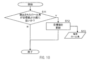
- control unit may control the left / right tilt angle control mechanism so as to approach a target value.
- the control unit may update the target value in accordance with a rider's input to the lean vehicle regarding a lean of a vehicle body frame in a left-right direction of the lean vehicle.
- the control unit controls the inclination angle of the vehicle body frame by the left / right inclination angle control mechanism during travel and the left / right inclination angle control mechanism during a stop.
- the control of the inclination angle of the body frame can be varied. This makes it possible to perform tilt angle control suitable for traveling and stopping.
- the input to the lean vehicle of the rider that causes the tilt angle control of the vehicle body frame during traveling may be different from the input to the lean vehicle of the rider that causes the tilt angle control of the vehicle body frame when the vehicle is stopped.
- control method by the control unit in any of the first to seventh configurations is also included in the embodiment of the present invention.
- a program for causing a computer to execute control of the control unit and a non-transitory recording medium in which the program is recorded are also included in the embodiments of the present invention.
- the roll angle has the same meaning as the lean angle of the body frame in the left-right direction of the lean vehicle.
- the roll angle control mechanism has the same meaning as the left / right tilt angle control mechanism.
- the vehicle control method is also one embodiment of the present invention.
- the vehicle in the control method is provided between a body frame, a right wheel and a left wheel arranged side by side in the left-right direction of the body frame, and between the body frame and the right wheel and the left wheel.
- a link mechanism including an arm rotatably supported with respect to the body frame, wherein the relative position of the right wheel and the left wheel with respect to the body frame is changed by rotating the arm with respect to the body frame;
- the control method includes detecting a rider's input to the vehicle when the vehicle is stopped, and changing the roll angle of the body frame according to the input to the rider's vehicle when the vehicle is stopped. Controlling the roll angle control mechanism.
- FIG. 1 is a left side view of the entire vehicle according to the embodiment as viewed from the left side.
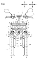
- FIG. 2 is a front view of a part of the vehicle of FIG. 1 as viewed from the front.
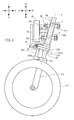
- FIG. 3 is a left side view of a part of the vehicle of FIG. 1 as viewed from the left.
- FIG. 4 is a plan view of a part of the vehicle of FIG. 1 as viewed from above.
- FIG. 5 is a plan view of a part of the vehicle of FIG. 1 viewed from above during right steering.
- FIG. 6 is a front view of a part of the vehicle shown in FIG.
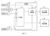
- FIG. 7 is a block diagram illustrating a configuration example of the vehicle control system according to the embodiment.
- FIG. 1 is a left side view of the entire vehicle according to the embodiment as viewed from the left side.
- FIG. 2 is a front view of a part of the vehicle of FIG. 1 as viewed from the front.
- FIG. 3 is a left side view of a
- FIG. 8 is a timing chart showing an example of roll angle and suspension control by the control unit shown in FIG.
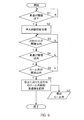
- FIG. 9 is a flowchart illustrating an example of processing in which the determination unit determines the start of roll angle control and suspension expansion / contraction suppression.
- FIG. 10 is a flowchart illustrating an example of a process in which the control unit updates the roll angle target value.
- FIG. 11 is a flowchart illustrating an example of processing in which the determination unit determines whether to release roll angle control and suspension expansion / contraction suppression.
- FIG. 12 is a timing chart illustrating another example of control by the control unit.
- FIG. 13 is a flowchart illustrating an example of processing in which the control unit executes roll angle control when the vehicle is stopped.
- FIG. 14 is a diagram illustrating a modification of the link mechanism.
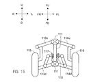
- FIG. 15 is a diagram illustrating another modification of the link mechanism.
- FIG. 16 is a diagram showing still another modified example of the link mechanism.
- the inventors tried to control the inclination (roll angle) of the vehicle at low speed using an actuator. Specifically, the actuator is operated so that the body frame is in an upright state when the body frame is tilted and the speed of the vehicle falls below a threshold value. The inventors examined in detail the use scene of such roll angle control.
- the inventors paid attention to the control of the inclination angle of the vehicle body frame at the start.
- the inventors have studied a control for maintaining the lateral inclination angle of the vehicle body frame near the upright state by the actuator until the vehicle speed reaches a threshold value after starting. In this case, the control of the tilt angle in the left-right direction of the vehicle body frame by the actuator is canceled when the vehicle speed becomes equal to or higher than the threshold after the start.
- the inventors examined in detail the roll angle control by the actuator and the movement of the rider at the start. As a result, it was found that the rider's operation immediately after starting changes depending on the situation. For example, the control of the vehicle posture by the rider after starting differs between when going straight after starting and when turning right or left.
- the vehicle body frame is kept close to the upright state by the actuator until the vehicle speed reaches the threshold after starting. After the vehicle speed exceeds the threshold value, the inclination angle of the body frame is controlled mainly by the rider operation. At this time, the rider controls the vehicle posture according to the situation.
- the inventors conducted further studies and found that the operation of the rider not only at the time of starting but also at the time of stopping before starting changes slightly depending on the situation. It has also been found by the inventors that, depending on the situation, the rider may want to keep the vehicle slightly tilted from the vertical direction when starting. Based on the above knowledge, the inventors have come up with a configuration in which the inclination angle of the vehicle body frame is controlled by the actuator based on the rider's operation when the vehicle is stopped. With this configuration, it is possible to control the inclination angle of the vehicle body frame more reflecting the rider's intention. Specifically, the inventors have conceived the configuration of the lean vehicle of the following embodiment.
- the lean vehicle in the present embodiment includes a vehicle body frame and right and left wheels arranged side by side in the left-right direction of the vehicle body frame.
- the vehicle body frame tilts to the right when turning to the right in the left-right direction of the lean vehicle, and leans to the left when turning to the left.
- the lean vehicle includes a link mechanism.
- the link mechanism includes an arm that is rotatably supported with respect to the body frame.
- the arm supports the right wheel and the left wheel.
- the relative positions of the right wheel and the left wheel in the vertical direction with respect to the body frame change.
- the vehicle body frame tilts in the left-right direction of the lean vehicle.
- the lean vehicle includes a left / right tilt angle control mechanism and a control unit that controls the left / right tilt angle control mechanism.
- the left / right inclination angle control mechanism includes an actuator that adjusts rotation of the arm with respect to the body frame.
- the left / right inclination angle control mechanism controls an inclination angle of the vehicle body frame in the left / right direction of the lean vehicle.
- the control unit is configured to change the inclination angle of the vehicle body frame according to an input to the lean vehicle by a rider regarding an inclination of the vehicle body frame in a left-right direction of the lean vehicle when the lean vehicle stops. Controls the right / left tilt angle control mechanism.
- the control unit changes the inclination angle of the vehicle body frame in the left-right direction when the vehicle is stopped, in accordance with the rider's input to the lean vehicle when the vehicle is stopped.
- the control unit uses the rider's input related to the tilt of the body frame in the left-right direction to control the tilt angle.
- the inventors further examined the relationship between the rider's input to the lean vehicle and the operation of the rider's vehicle after starting. As a result, it has been found that the rider tends to control the posture of the lean vehicle at the start by the steering operation at the time of stopping. Based on this knowledge, the inventors have a configuration in which the control unit controls the left / right tilt angle control mechanism so as to change the left / right tilt angle of the vehicle body frame according to the steering angle of the steering wheel when the lean vehicle stops. I came up with it. According to this configuration, it is possible to control the tilt angle in the left-right direction of the vehicle body frame when the vehicle is stopped according to the input of the steering force applied to the rider's handle when the vehicle is stopped. Thereby, the roll angle of the vehicle body frame at the time of starting can be made in line with the rider's intention.
- the arrow F indicates the front direction of the vehicle.
- Arrow B indicates the backward direction of the vehicle.
- An arrow U indicates the upward direction of the vehicle.
- An arrow D indicates the downward direction of the vehicle.
- An arrow R indicates the right direction of the vehicle.
- An arrow L indicates the left direction of the vehicle.
- an arrow FF indicates the front direction of the body frame.
- An arrow FB indicates the rear direction of the vehicle body frame.
- An arrow FU indicates the upward direction of the vehicle body frame.
- An arrow FD indicates the downward direction of the vehicle body frame.
- An arrow FR indicates the right direction of the body frame.
- An arrow FL indicates the left direction of the body frame.
- the longitudinal direction of the vehicle body frame “the lateral direction of the vehicle body frame”, and “the vertical direction of the vehicle body frame” are the longitudinal direction with respect to the vehicle body frame as viewed from the occupant driving the vehicle, It means the horizontal direction and the vertical direction.
- the “side of the body frame” means the right direction or the left direction of the body frame.
- extending in the front-rear direction of the body frame includes extending in a direction inclined with respect to the front-rear direction of the body frame.
- the inclination of the body frame in the extending direction with respect to the front-rear direction is often smaller than the inclination of the body frame with respect to the left-right direction and the vertical direction.
- “extending in the left-right direction of the body frame” includes extending in a direction inclined with respect to the left-right direction of the body frame.
- the inclination of the body frame in the extending direction with respect to the left-right direction is often smaller than the inclination of the body frame with respect to the front-rear direction and the up-down direction.
- “extending in the vertical direction of the vehicle body frame” includes extending in a direction inclined with respect to the vertical direction of the vehicle body frame.
- the inclination of the body frame in the extending direction with respect to the vertical direction is often smaller than the inclination of the body frame with respect to the front-rear direction and the left-right direction.
- the “upright state of the body frame” means a state in which the vertical direction of the body frame coincides with the vertical direction. In this state, the direction based on the vehicle coincides with the direction based on the vehicle frame.
- the left-right direction of the vehicle does not match the left-right direction of the body frame.
- the vertical direction of the vehicle does not match the vertical direction of the body frame.
- the front-rear direction of the vehicle and the front-rear direction of the body frame coincide.
- the “roll angle of the body frame” means an angle of rotation of the body frame around the front-rear direction.
- the roll angle of the body frame has the same meaning as the inclination angle of the body frame in the left-right direction of the vehicle.
- the roll angle can be expressed as an angle in the vertical direction of the body frame with respect to the vertical direction.
- the vertical direction is the same as the gravity direction.
- FIG. 1 is a left side view of the entire vehicle 1 as viewed from the left.
- the vehicle 1 includes a vehicle body 2, a pair of left and right front wheels 3, a rear wheel 4, a link mechanism 5, and a steering mechanism 7.
- the vehicle body 2 includes a body frame 21, a body cover 22, a seat 24, and a power unit 25.
- the body frame 21 is in an upright state.
- the subsequent description with reference to FIG. 1 is based on the upright state of the body frame 21.
- the vehicle 1 is a lean vehicle. When the vehicle 1 turns, the body frame 21 tilts in the turning direction.
- the vehicle body frame 21 includes a head pipe 211, a down frame 212, and a rear frame 213. In FIG. 1, a portion of the body frame 21 hidden by the body cover 22 is indicated by a broken line.
- the vehicle body frame 21 supports the seat 24 and the power unit 25.
- the power unit 25 supports the rear wheel 4.
- the power unit 25 includes a drive source such as an engine, an electric motor, and a battery, and a device such as a transmission.
- the head pipe 211 is disposed in the front portion of the vehicle 1. When viewed from the side of the vehicle body frame 21, the upper part of the head pipe 211 is disposed behind the lower part of the head pipe 211.
- the down frame 212 is connected to the head pipe 211.
- the down frame 212 is disposed behind the head pipe 211.
- the down frame 212 extends in the vertical direction of the body frame 21.
- the rear frame 213 is disposed behind the down frame 212.
- the rear frame 213 extends in the front-rear direction of the body frame 21.
- the rear frame 213 supports the seat 24 and the power unit 25.
- the vehicle body cover 22 includes a front cover 221, a front spoiler 222, a pair of left and right front fenders 223, a rear fender 224, and a leg shield 225.
- the vehicle body cover 22 is a vehicle body part that covers at least a part of vehicle body parts mounted on the vehicle 1 such as a pair of left and right front wheels 3, a vehicle body frame 21, and a link mechanism 5.
- FIG. 2 is a front view of the front portion of the vehicle 1 as viewed from the front of the vehicle body frame 21.
- the body frame 21 is in an upright state.
- the subsequent description referring to FIG. 2 is based on the upright state of the body frame 21.
- FIG. 2 shows a state in which the front cover 221, the front spoiler 222, and the pair of left and right front fenders 223 are removed.
- the pair of front wheels 3 includes a right wheel 31 and a left wheel 32 arranged side by side on the left and right of the head pipe 211 (body frame 21).
- the link mechanism 5 and the suspension (the right suspension 33 and the left suspension 35) are provided between the head pipe 211 that is a part of the vehicle body frame 21 and the pair of front wheels 3. That is, the body frame 21 is connected to the right wheel 31 and the left wheel 32 via the link mechanism 5 and the suspensions 33 and 35.
- the link mechanism 5 is disposed below the handle 23.
- the link mechanism 5 is disposed above the right wheel 31 and the left wheel 32.
- the link mechanism 5 is connected to the right wheel 31 and the left wheel 32 via suspensions 33 and 35.
- the arrangement configuration of the suspensions 33 and 35 is not limited to this.
- a suspension may be provided in a part of the link mechanism 5.
- a suspension may be provided between the link mechanism 5 and the vehicle body frame 21.
- the link mechanism 5 of the vehicle 1 shown in FIG. 2 is a parallel four-bar link (also called parallelogram link) type link mechanism.
- the link mechanism 5 includes an upper arm 51, a lower arm 52, a right side member 53, and a left side member 54.
- the link mechanism 5 includes an upper arm 51 and a lower arm 52 (hereinafter collectively referred to as arms 51 and 52 unless otherwise distinguished) that are rotatably supported with respect to the vehicle body frame 21.
- the arms 51 and 52 are rotatable with respect to the vehicle body frame 21 around a rotation axis extending in the front-rear direction.
- the rotation axis is arranged at the center in the left-right direction of the arms 51 and 52. That is, the intermediate portions of the arms 51 and 52 are supported by the head pipe 211 by the support portions A and D.
- the rotation axes of the arms 51 and 52 pass through the support portions A and D.
- a right wheel 31 is disposed to the right of the rotation shaft
- a left wheel 32 is disposed to the left of the rotation shaft.
- the right wheel 31 is connected to the right part of the rotation shafts of the arms 51 and 52 via the right side member 53 and the right suspension 33.
- the left wheel 32 is connected to the left part of the rotating shafts of the arms 51 and 52 via the left side member 54 and the left suspension 35.
- the relative positions of FU and FD can be changed. That is, as the arms 51 and 52 rotate, the relative positions of the right wheels 31 and the left wheels 32 disposed on the left and right of the rotation shafts of the arms 51 and 52 in the vertical directions FU and FD change with respect to the vehicle body frame 21.
- the relative positions of the right wheel 31 and the left wheel 32 in the up and down directions FU and FD change, the body frame 21 tilts in the left and right direction with respect to the vertical direction. Therefore, by adjusting the rotation of the arms 51 and 52 with respect to the vehicle body frame 21, the horizontal inclination of the vehicle body frame 21, that is, the roll angle can be controlled.
- the upper arm 51 includes a pair of plate-like members 512.
- the pair of plate-like members 512 are disposed in front of and behind the head pipe 211. Each plate-like member 512 extends in the left-right direction of the body frame 21.
- the lower arm 52 includes a pair of plate-like members 522. The pair of plate-like members 522 are disposed in front of and behind the head pipe 211. Each plate-like member 522 extends in the left-right direction of the body frame 21.
- the lower arm 52 is disposed below the upper arm 51.
- the length dimension of the lower arm 52 in the left-right direction of the body frame 21 is the same as or equivalent to the length dimension of the upper arm 51 in the left-right direction of the body frame 21.
- the lower arm 52 extends in parallel with the upper arm 51.
- the configuration of the arms 51 and 52 is not limited to the above example.
- the arms 51 and 52 can also be configured with a single plate-shaped member disposed in front of the head pipe 211.
- the right end of the upper arm 51 and the right end of the lower arm 52 are connected to a right side member 53 that extends in the vertical direction of the body frame 21.
- the right side member 53 is rotatably supported by the upper arm 51 and the lower arm 52 by the support portions B and E.
- the right side member 53 is rotatable with respect to the upper arm 51 and the lower arm 52 around a rotation axis that passes through the support portions B and E and extends in the front-rear direction.
- the left end of the upper arm 51 and the left end of the lower arm 52 are connected to a left side member 54 that extends in the vertical direction of the body frame 21.
- the left side member 54 is rotatably supported by the upper arm 51 and the lower arm 52 by the support portions C and F.
- the left side member 54 is rotatable with respect to the upper arm 51 and the lower arm 52 around a rotation axis that passes through the support portions C and F and extends in the front-rear direction.
- the lower end of the right side member 53 is connected to the right suspension 33 via the right bracket 317.
- the lower ends of the left side member 54 and the left suspension 35 are connected to the left suspension 35 via the left bracket 327.
- the right suspension 33 and the left suspension 35 can extend and contract in the vertical direction of the body frame 21.
- the upper end of the right suspension 33 is connected to the link mechanism 5, and the lower end is connected to the right wheel 31.
- the upper end of the left suspension 35 is connected to the link mechanism 5, and the lower end is connected to the left wheel 32.
- the suspensions 33 and 35 are, for example, telescopic suspensions.
- the suspension can also be referred to as a shock absorber.
- the right suspension 33 includes a right outer cylinder 312 that supports the right wheel 31 and a right inner cylinder 316 that is disposed above the right outer cylinder 312.
- the upper end of the right inner cylinder 316 is fixed to the right bracket 317, and the lower end is inserted into the right outer cylinder 312.
- the left suspension 35 includes a left outer cylinder 322 that supports the left wheel 32 and a left inner cylinder 326 that is disposed above the left outer cylinder 322.
- the upper end of the left inner cylinder 326 is fixed to the left bracket 327, and the lower end is inserted into the left outer cylinder 322.
- the left suspension 35 expands and contracts.
- a right rotation prevention mechanism 34 is connected between the right bracket 317 and the right outer cylinder 312.
- the right rotation prevention mechanism 34 prevents the right outer cylinder 312 from rotating with respect to the right inner cylinder 316 about an axis extending in the expansion / contraction direction of the right suspension 33.
- a left rotation prevention mechanism 36 is connected between the left bracket 327 and the left outer cylinder 322. The left rotation prevention mechanism 36 prevents the left outer cylinder 322 from rotating with respect to the left inner cylinder 326 around an axis extending in the extension / contraction direction of the left suspension 35.
- the right rotation prevention mechanism 34 includes a right rotation prevention rod 341, a right guide 313, and a right bracket 317.
- the right guide 313 is fixed to the upper portion of the right outer cylinder 312.
- the right guide 313 has a right guide cylinder 313b at the front thereof.
- the right rotation prevention rod 341 extends in parallel with the right inner cylinder 316.
- the upper portion of the right rotation prevention rod 341 is fixed to the front portion of the right bracket 317.
- the right rotation prevention rod 341 is disposed in front of the right inner cylinder 316 in a state where a part thereof is inserted into the right guide cylinder 313b. Thereby, the right rotation prevention rod 341 does not move relative to the right inner cylinder 316.
- the right rotation prevention rod 341 also moves relative to the right guide cylinder 313b.
- the right outer cylinder 312 is prevented from rotating with respect to the right inner cylinder 316 about an axis extending in the expansion / contraction direction of the right suspension 33.
- the left rotation prevention mechanism 36 includes a left rotation prevention rod 361, a left guide 323, and a left bracket 327.
- the left guide 323 is fixed to the upper part of the left outer cylinder 322.
- the left guide 323 has a left guide cylinder 323b at the front thereof.
- the left rotation prevention rod 361 extends in parallel with the left inner cylinder 326.
- the upper part of the left rotation prevention rod 361 is fixed to the front part of the left bracket 327.
- the left rotation prevention rod 361 is disposed in front of the left inner cylinder 326 in a state where a part thereof is inserted into the left guide cylinder 323b. Thereby, the left rotation prevention rod 361 does not move relative to the left inner cylinder 326.
- the left rotation prevention rod 361 also moves relative to the left guide cylinder 323b.
- the left outer cylinder 322 is prevented from rotating with respect to the left inner cylinder 326 around an axis extending in the extending and contracting direction of the left suspension 35.
- the configuration of the suspension is not limited to the above example.
- the right suspension 33 may be configured by arranging two combinations of the right outer cylinder 312 and the inner cylinder 316 that move relative to each other.
- the left suspension 35 can similarly be configured by arranging two combinations of the left outer cylinder 322 and the left inner cylinder 326 side by side. This is a double telescopic suspension.
- by connecting the pair of outer cylinders and the inner cylinders of the suspensions 33 and 35 so that they cannot move relative to each other it can also serve as an anti-rotation mechanism. In that case, the right rotation prevention mechanism 34 and the left rotation prevention mechanism 36 as described above are unnecessary.
- the vehicle 1 includes a roll angle control mechanism 74 that controls the roll angle of the body frame 21.
- the roll angle control mechanism 74 is indicated by a dotted line.
- the roll angle control mechanism 74 adjusts the rotation of the arms 51 and 52 with respect to the vehicle body frame 21.
- the roll angle of the body frame 21 is controlled by adjusting the rotation of the arms 51 and 52.
- the roll angle control mechanism 74 is connected to the vehicle body frame 21 and at least one of the arm 51 or the lower arm 52.
- the adjustment of the rotation of the arms 51 and 52 by the roll angle control mechanism 74 controls not only simple locking and unlocking of the arms 51 and 52 but also the rotational force. That is, the roll angle control mechanism 74 can be configured to adjust the rotation of the arms 51 and 52 by generating torque that rotates the arms 51 and 52 with respect to the vehicle body frame 21 or resistance to the torque. . For example, the roll angle control mechanism 74 can be configured such that the magnitude of the force for rotating the arms 51 and 52 is variable.
- the roll angle control mechanism 74 can adjust the rotation of the arms 51 and 52 so that the roll angle of the vehicle body frame 21 becomes an arbitrarily set target value. At that time, the roll angle control mechanism 74 monitors the actual roll angle of the body frame 21 or the torque of the arms 51 and 52, and determines the magnitude and direction of the force for rotating the arms 51 and 52 using the monitoring result. Can do.
- FIG. 3 is a left side view of the front portion of the vehicle 1 as viewed from the left side of the vehicle body frame 21.
- the vehicle body frame 21 is in an upright state.
- the subsequent description referring to FIG. 3 is based on the upright state of the body frame 21.
- FIG. 3 shows a state in which the front cover 221, the front spoiler 222, and the pair of left and right front fenders 223 are removed. Further, illustration of the left side member 54 and the left transmission plate 63 is omitted.
- the roll angle control mechanism 74 includes an actuator 42 that adjusts the rotation of the arms 51 and 52 with respect to the vehicle body frame 21.
- the actuator 42 is connected to the head pipe 211 (the vehicle body frame 21) via the support member 43.
- the actuator 42 is fixed to the vehicle body frame 21 by the support member 43.
- the actuator 42 has an output member 461 that applies a rotational force in contact with the upper arm 51.
- the output member 461 is an output shaft that rotates about an axis.
- the output shaft of the output member 461 is coaxial with the rotational axis of the upper arm 51. The rotation of these output shafts is transmitted to the rotation shaft of the upper arm 51.
- the actuator 42 can include a motor that is a power source and a speed reducer that decelerates and outputs the rotational speed of the motor.
- the reduction gear can be, for example, a reduction gear that is interlocked with the rotation of the motor.
- the output member 461 transmits the rotation of the motor and the speed reducer to the outside.
- the actuator 42 can operate based on a control signal from a control unit (not shown) provided in the vehicle 1. For example, the actuator 42 can adjust the rotational force applied to the arms 51 and 52 so that the roll angle of the body frame 21 becomes a target value instructed by the control unit.
- the actuator 42 can also control the output based on a signal from a sensor that detects the state of the vehicle 1. Examples of the sensor that indicates the state of the vehicle include a posture sensor that detects the posture of the vehicle 1, a torque sensor that detects torque of rotation of the arms 51 and 52 with respect to the vehicle body frame, and the like.
- the process of determining the output of the actuator 42 based on information from the sensor may be executed by a control circuit or a control computer built in the actuator 42 or may be executed by a control device outside the actuator 42. .
- the configuration of the actuator 42 is not limited to the above example.
- the actuator 42 may be connected to at least one of the upper arm 51 and the lower arm 52 and adjust the rotation of at least one of them.
- the output member of the actuator 42 may have a shaft shape extending in one axial direction, and may apply a rotational force to the arms 51 and 52 by expanding and contracting in the axial direction.
- the actuator can be configured such that one end is rotatably connected to the arms 51 and 52 and the other end is rotatably connected to the vehicle body frame 21. The one end is connected to a portion of the arms 51 and 52 away from the rotation axis.
- the arms 51 and 52 can be rotated with respect to the vehicle body frame 21 by expanding and contracting in the direction connecting the one end and the other end.
- the actuator 42 may be a hydraulic actuator. That is, the power source of the actuator can be electric or hydraulic.
- the actuator 42 may be a damper device that applies a damping force to the torque that rotates the arms 51 and 52.
- the vehicle 1 can include a suspension control mechanism that suppresses expansion and contraction of the suspensions 33 and 35 (see FIG. 2).
- the suspension control mechanism can be provided inside the suspensions 33 and 35, for example.
- the suspensions 33 and 35 include the inner cylinders 316 and 326 and the outer cylinders 312 and 322. As the suspensions 33 and 35 expand and contract, oil flows inside.
- the suspensions 33 and 35 are provided with an orifice that is an oil flow path and an adjustment valve that adjusts the flow rate in the oil flow path.
- the suspension control mechanism can be configured to control this adjustment valve.
- the adjusting mechanism of the adjusting valve can be mechanical or electric.
- the position of the adjustment valve can be controlled by a motor or a solenoid.
- the regulating valve can be an electromagnetic regulating valve.
- the suspension control mechanism may be configured to adjust the magnetic fluid viscosity with a solenoid.
- the suspension control mechanism can control the regulating valve based on a signal from the control unit of the vehicle 1.
- the suspension control mechanism adjusts the flow rate of oil inside the suspensions 33 and 35 by controlling the opening and closing of the regulating valve.
- the suspension control mechanism can suppress the expansion and contraction of the suspensions 33 and 35 by reducing the flow rate. Further, the suspension control mechanism can release the suppression of the expansion and contraction of the suspensions 33 and 35 by increasing the flow rate. For example, when the adjustment valve is closed, the expansion and contraction of the suspensions 33 and 35 is suppressed, and when the adjustment valve is opened, the suppression of the expansion and contraction of the suspensions 33 and 35 is released (extension and contraction operation is allowed).
- a suspension control mechanism can be added to the right rotation prevention mechanism 34 and the left rotation prevention mechanism 36.
- brake shoes can be provided on the guide cylinders 313b and 323b into which the rotation prevention rods 341 and 361 are inserted.
- the brake shoe can be operated by an actuator such as a motor or a hydraulic actuator, for example.
- the brake shoe actuator can be attached to the vehicle body frame 21, for example.
- the configuration of the brake used as the suspension control mechanism is not limited to the above example.
- the brake can be configured to have a caliper or to limit the expansion and contraction of the suspension by breaking the parallel relationship between the expansion and contraction direction of the rotation prevention mechanism and the expansion and contraction direction of the suspension.
- the suspension control mechanism is provided independently from the actuator 42 of the roll angle control mechanism 74.
- an actuator for suppressing expansion and contraction of the suspensions 33 and 35 is separately provided.
- the power source of the suspension control mechanism can be provided separately from the power source of the roll angle control mechanism 74.
- the expansion / contraction suppression control of the suspensions 33 and 35 can be performed without being restricted by the roll angle control.
- the roll angle control can be performed independently of the expansion / contraction suppression control of the suspensions 33 and 35.
- the steering mechanism 7 includes a handle 23 and a steering force transmission mechanism 6.
- the steering force transmission mechanism 6 includes a steering shaft 60 and a tie rod 67.
- brackets 317 and 327 and suspensions 33 and 35 are also included in the steering force transmission mechanism 6.
- the steering force transmission mechanism 6 is supported by the head pipe 211 at the front portion of the vehicle body frame 21 so as to be rotatable integrally with the handle 23.
- the steering force transmission mechanism 6 changes the direction of the right wheel 31 and the left wheel 32 according to the rotation of the handle 23. That is, the steering force transmission mechanism 6 transmits the steering force input to the handle 23 when the rider operates the handle 23 to the right wheel 31 and the left wheel 32 via the right bracket 317 and the left bracket 327.
- the rotation axis Z of the steering shaft 60 extends in the vertical direction of the body frame 21.
- the handle 23 is attached to the upper part of the steering shaft 60.
- the steering shaft 60 rotates about the rotation axis Z according to the operation of the handle 23 by the rider.
- a part of the steering shaft 60 is rotatably supported by the head pipe 211.
- a lower portion of the steering shaft 60 is connected to a tie rod 67 extending in the left-right direction via an intermediate transmission plate 61.
- the intermediate transmission plate 61 is not rotatable relative to the steering shaft 60. That is, the intermediate transmission plate 61 can rotate together with the steering shaft 60 around the direction in which the steering shaft 60 extends.
- the right end of the tie rod 67 is connected to the right bracket 317 via the right transmission plate 62.
- the right transmission plate 62 can rotate together with the right side member 53 around the direction in which the right side member 53 extends.
- the left end of the tie rod 67 is connected to the left bracket 327 via the left transmission plate 63.
- the left transmission plate 63 can rotate with the left side member 54 around the direction in which the left side member 54 extends.
- FIG. 4 is a plan view of the front portion of the vehicle 1 as viewed from above the vehicle body frame 21.
- the body frame 21 is in an upright state.
- the subsequent description referring to FIG. 4 is based on the upright state of the body frame 21.
- FIG. 4 shows a state where the front cover 221 is removed.
- a direction in which the right side member 53 extends is a right center axis X
- a direction in which the left side member 54 extends is a left center axis Y.
- the right center axis X and the left center axis Y extend in parallel with the rotation axis Z of the steering shaft 60.
- the intermediate transmission plate 61, the right transmission plate 62, and the left transmission plate 63 are connected to the tie rod 67 via the intermediate front rod 641, the right front rod 651, and the left front rod 661, respectively.
- the intermediate front rod 641, the right front rod 651, and the left front rod 661 extend in the front-rear direction of the vehicle body frame 21, and are rotatable about the extending direction. Accordingly, the intermediate front rod 641, the right front rod 651, and the left front rod 661 are connected to the tie rod 67 so as to be rotatable about an axis extending in the front-rear direction.
- the intermediate front rod 641, the right front rod 651, and the left front rod 661 are connected to the intermediate transmission plate 61, the right transmission plate 62, and the left transmission plate 63 via the intermediate joint 64, the right joint 65, and the left joint 66, respectively. Is done.
- the intermediate front rod 641 is rotatable relative to the intermediate transmission plate 61 around an axis parallel to the rotation axis Z.
- the right front rod 651 is rotatable relative to the right transmission plate 62 about an axis parallel to the right center axis X.
- the left front rod 661 can rotate relative to the left transmission plate 63 about an axis parallel to the left central axis Y.
- FIG. 5 is a plan view of the front portion of the vehicle 1 viewed from above the body frame 21 in a state where the right wheel 31 and the left wheel 32 are turned to the right.
- the steering shaft 60 rotates relative to the head pipe 211 about the rotation axis Z.
- the steering shaft 60 rotates in the direction of the arrow G.
- the intermediate transmission plate 61 rotates about the rotation axis Z in the direction of the arrow G with respect to the head pipe 211.
- the intermediate transmission plate 61 rotates in the direction of arrow G
- the intermediate front rod 641 of the tie rod 67 rotates with respect to the intermediate transmission plate 61 in the direction opposite to the arrow G around the intermediate joint 64.
- the tie rod 67 moves to the right rear while maintaining its posture.
- the right front rod 651 and the left front rod 661 of the tie rod 67 rotate in the direction opposite to the arrow G around the right joint 65 and the left joint 66, respectively.
- the right transmission plate 62 and the left transmission plate 63 rotate in the direction of arrow G while maintaining the posture of the tie rod 67.
- the steering force transmission mechanism 6 transmits the steering force to the right wheel 31 and the left wheel 32 in accordance with the operation of the handle 23 by the occupant.
- the right wheel 31 and the left wheel 32 rotate about the right center axis X and the left center axis Y, respectively, in a direction corresponding to the operation direction of the handle 23 by the rider.
- FIG. 6 is a front view of the front portion of the vehicle 1 in a state in which the vehicle body frame 21 is tilted to the left as viewed from the front of the vehicle body frame 21.
- the link mechanism 5 in the upright state of the vehicle body frame 21, when the vehicle 1 is viewed from the front of the vehicle body frame 21, the link mechanism 5 has a rectangular shape. As shown in FIG. 6, when the vehicle body 21 is inclined, the link mechanism 5 has a parallelogram shape when the vehicle 1 is viewed from the front of the vehicle body frame 21.
- the deformation of the link mechanism 5 and the inclination of the body frame 21 in the left-right direction are linked.
- the operation of the link mechanism 5 refers to the relative rotation of the upper arm 51, the lower arm 52, the right side member 53, and the left side member 54 constituting the link mechanism 5 around the rotation axis passing through the respective support portions A to F. This means that the shape of the link mechanism 5 changes.
- the head pipe 211 that is, the vehicle body frame 21
- the vehicle body frame 21 tilts to the left with respect to the vertical direction.
- the upper arm 51 rotates about the axis passing through the support portion A counterclockwise as viewed from the rider with respect to the vehicle body frame 21.
- the lower arm 52 rotates counterclockwise around an axis passing through the support portion D.
- the upper arm 51 moves to the left with respect to the lower arm 52.
- the upper arm 51 rotates counterclockwise with respect to the right side member 53 and the left side member 54 about the axis passing through the support part B and the axis passing through the support part C, respectively.
- the lower arm 52 rotates counterclockwise with respect to the right side member 53 and the left side member 54 around the axis line passing through the support part E and the axis line passing through the support part F, respectively.
- the right side member 53 and the left side member 54 are inclined leftward with respect to the vertical direction while maintaining a posture parallel to the vehicle body frame 21.
- the lower arm 52 moves to the left with respect to the tie rod 67.
- the intermediate front rod 641, right front rod 651, and left front rod 661 of the tie rod 67 rotate with respect to the tie rod 67.
- the tie rod 67 maintains a posture parallel to the upper arm 51 and the lower arm 52.
- the right wheel 31 connected to the right side member 53 via the right bracket 317 and the right suspension 33 is leftward while maintaining a posture parallel to the vehicle body frame 21. Inclined to.
- the left wheel 32 connected to the left side member 54 via the left bracket 327 and the left suspension 35 is leftward while maintaining a posture parallel to the body frame 21. Inclined to.
- the above description regarding the tilting operation of the right wheel 31 and the left wheel 32 is based on the vertical direction.
- the vertical direction of the body frame 21 does not coincide with the vertical vertical direction.
- the relative positions of the right wheel 31 and the left wheel 32 with respect to the body frame 21 are changed when the link mechanism 5 is operated.
- the link mechanism 5 tilts the vehicle body frame 21 with respect to the vertical direction by changing the relative position of the right wheel 31 and the left wheel 32 to the vehicle body frame 21 in the vertical direction of the vehicle body frame 21.
- FIG. 7 is a block diagram illustrating a configuration example of the control system of the vehicle 1.
- the control unit 71 controls the roll angle control mechanism 74 and the suspension control mechanism 75 based on information indicating the state of the vehicle.
- the control unit 71 is connected to the roll angle control mechanism 74 and the suspension control mechanism 75 wirelessly or by wire.
- the control unit 71 is configured to be able to transmit a control signal to the drive unit of the roll angle control mechanism 74 and the drive unit of the suspension control mechanism 75.
- the drive unit of the roll angle control mechanism 74 can be, for example, a drive circuit for the actuator 42 of the roll angle control mechanism 74.
- the drive unit of the suspension control mechanism 75 can be, for example, an actuator or a damping circuit of the suspension control mechanism 75.
- control unit 71 is connected to a sensor that detects the state of the vehicle 1 by wireless or wired.
- the control unit 71 receives information indicating the state of the vehicle 1 from the sensor.
- a steering angle sensor 76, a throttle sensor 77, a vehicle speed sensor 78, and an attitude angle sensor 79 are connected to the control unit 71.
- the rudder angle sensor 76 sends a signal corresponding to the rotation angle and the rotation direction of the steering shaft 60 to the control unit 71.
- the steering angle sensor 76 is attached to the steering shaft 60, for example, and detects the rotation of the steering shaft 60 with respect to the vehicle body frame 21.
- the throttle sensor 77 sends a signal corresponding to the throttle opening of the vehicle 1 to the control unit 71.
- the throttle sensor 77 is attached to the engine of the vehicle 1, for example, and detects the throttle opening of the engine throttle valve.
- the vehicle speed sensor 78 sends a signal corresponding to the traveling speed of the vehicle 1 to the control unit 71.
- the vehicle speed sensor 78 may detect the rotational speed of the wheel.
- the vehicle speed sensor 78 is attached to, for example, the axle of the front wheel 3 or the rear wheel 4, the output shaft of the transmission, and the like, and sends a signal corresponding to the rotational speed of the wheel to the control unit 71.
- the attitude angle sensor 79 sends a signal corresponding to the roll angle of the body frame 21 to the control unit 71.
- the attitude angle sensor 79 can be a gyroscope that detects the roll angular velocity and the roll angle of the body frame 21.
- the gyroscope can be a three-axis gyroscope that detects an angular velocity or an angle of a yaw angle and a pitch angle in addition to a roll angle. Note that the attitude angle sensor 79 is not limited to a gyroscope.
- an acceleration sensor a sensor that detects the rotation angle, angular velocity, or torque of the arms 51 and 52 with respect to the body frame 21, a sensor that detects the angle of the pendulum suspended from the body frame 21, and a torque applied to the actuator are detected.
- the sensor, the current detector of the actuator, or a combination of at least two of these sensors can be the attitude angle sensor 79.
- the sensor connected to the control unit 71 is not limited to the above example.
- the control unit 71 can receive information from
- the control unit 71 includes a determination unit 72 and an angle control unit 73.
- the determination unit 72 determines the control of the roll angle and the expansion and contraction of the suspension based on the information indicating the state of the vehicle acquired from the sensor groups 77 to 79.
- the angle control unit 73 controls the roll angle control mechanism based on the roll angle control determined by the determination unit 72 and the roll angle of the vehicle body frame 21 detected by the attitude angle sensor 79.
- the determination unit 72 determines whether or not the roll angle control during traveling for stopping is necessary based on the information indicating the state of the vehicle acquired from at least one of the sensor groups 77 to 79. This necessity determination includes the determination of the start or release of roll angle control during traveling toward the stop. For example, the determination unit 72 can determine whether or not the roll angle control during traveling for stopping is necessary based on a predetermined condition of the vehicle state. For example, when the vehicle condition satisfies the first condition, the determination unit 72 determines to start the roll angle control during traveling toward the stop, and performs the roll angle control when the second condition is satisfied. It can be determined to cancel.
- During traveling to stop is, for example, a traveling state in which it is determined that there is a high possibility of stopping within a few seconds. Whether the vehicle is traveling toward a stop can be determined, for example, based on whether the vehicle speed is below a predetermined threshold. The determination unit 72 determines that the roll angle control during the traveling toward the stop is to be performed when the behavior of the vehicle 1 traveling toward the stop is shown. Therefore, for example, when the speed is increased again from a state where the vehicle 1 is about to stop, the determination unit 72 may determine that the roll angle control during traveling toward the stop is performed.
- the low speed traveling region is a region where the vehicle speed is the lowest among a plurality of regions formed by dividing the entire vehicle speed region of the vehicle 1 except for the stop state. That is, the entire vehicle speed range of the vehicle 1 excluding the stop state can be divided into a high-speed travel region and a low-speed travel region.
- the low-speed traveling region can be a region where the vehicle speed v is greater than 0 and smaller than the upper limit value VLu (0 ⁇ v ⁇ VLu).
- the high-speed travel region is a region where the vehicle speed v is equal to or higher than VLu and is equal to or lower than the maximum speed Vmax of the vehicle 1 (VLu ⁇ v ⁇ Vmax).
- the upper limit value VLu of the low-speed traveling region is not limited to a specific value, and for example, a value corresponding to the type of vehicle is set.
- the vehicle speed threshold Th2 for determining whether or not the vehicle is traveling toward a stop is a vehicle speed value included in the low-speed traveling region.
- the roll angle control during traveling toward the stop can be, for example, a control that causes the roll angle to approach the set target value.
- the target value is determined by the control unit 71 based on the input to the rider's vehicle.
- the determination of the target value can be executed by either the determination unit 72 or the angle control unit 73.
- the control unit 71 determines the target value according to the rider's input to the vehicle when the determination unit 71 determines that the vehicle state satisfies the first condition.
- the control unit 71 detects the rider's input to the vehicle when it is determined that the state of the vehicle satisfies the first condition. It should be noted that the determination time point when the state of the vehicle satisfies the first condition and the detection time point of the input to the rider's vehicle may not be strictly the same.
- the control unit 7 can detect an input to the rider's vehicle from information obtained by the sensor groups 77 to 79 that detect the state of the vehicle. For example, the control unit 7 may use the information acquired from the sensor groups 77 to 79 as information indicating an input to the rider's vehicle, or may use the information acquired from the sensor groups 77 to 79 to input the rider's vehicle. It can also be judged.
- Examples of information detected by an in-vehicle sensor as an input to the rider's vehicle include, for example, vehicle speed, acceleration, throttle opening, brake operating state, body frame 21 roll angle, vehicle center of gravity movement, steering wheel steering angle, Examples of the movement of the body frame in three directions (acceleration, velocity, position), movement around three axes (acceleration, angular velocity, angle), seat pressure, and the like.
- the control unit 71 can also determine an input to the rider's vehicle from a combination of information detected by a plurality of sensors.
- the input to the rider's vehicle includes the case where the input is zero. That is, the control unit 7 can determine the roll angle control based on the fact that there is no input to the rider's vehicle for a certain event or the value indicating the input for a certain event is zero. For example, when the body frame 21 is kept upright while the rider is traveling, the detected roll angle is 0 degrees, and the time change of the roll angle is also zero. Also in such a case, information that the roll angle or its change is 0 can be used for determining the operation of the control unit 7. *
- the control unit 71 detects the roll angle of the body frame 21 as an input to the rider's vehicle.
- the control unit 71 acquires the roll angle of the body frame 21 from the attitude angle sensor 79. Thereby, the roll angle of the vehicle body frame 21 when the state of the vehicle 1 satisfies the first condition can be acquired.
- the control unit 71 sets the acquired roll angle as a target value.
- the angle control unit 73 controls the roll angle control mechanism 74 so that the roll angle of the body frame 21 becomes the set target value.
- the roll angle of the body frame 21 is maintained when it is determined that the state of the vehicle 1 satisfies the first condition, that is, when the vehicle is in a traveling state for stopping.
- the roll angle can be maintained when the vehicle 1 stops and after the vehicle stops. As a result, it is possible to run and stop the vehicle in the posture of the vehicle in accordance with the rider's intention.
- the controller 71 determines that the state of the vehicle 1 satisfies the first condition, that is, in response to an input to the vehicle 1 by the rider during a period in which the roll angle control during traveling toward the stop is executed.
- the target value of the roll angle can be updated.
- the target value can be updated in accordance with the actual roll angle of the vehicle body frame 21 during the period during which the roll angle control during traveling toward the stop is being executed.
- the control unit 71 controls the roll angle control mechanism so that the roll angle of the vehicle body frame 21 approaches 0 degrees with respect to the vertical direction in accordance with an operation by a rider who is traveling toward a stop. Can do. That is, when the rider performs an operation to bring the roll angle of the vehicle frame closer to 0 degrees with respect to the vertical direction during the roll angle control during traveling toward the stop, the control unit 71 responds to the operation by the rider.
- the roll angle control mechanism can be controlled so that the roll angle of the vehicle body frame 21 approaches 0 degrees with respect to the vertical direction. At this time, when the roll angle of the vehicle body frame 21 changes so as to approach 0 degree with respect to the vertical direction from the target value, the control unit 71 sets the changed roll angle as the target value. This allows the rider to incline the vehicle in a direction that brings the roll angle of the vehicle frame closer to 0 degrees with respect to the vertical direction during and after traveling toward the stop, but in the opposite direction. It is possible to perform control such that tilting is not allowed.
- the roll angle of the body frame approaches 0 degrees with respect to the vertical direction means that the roll angle of the body frame when the vertical direction of the body frame coincides with the vertical direction is 0 degrees. Is changed to approach 0 degrees.
- the determination unit 72 determines whether it is necessary to suppress expansion / contraction of the suspensions 33 and 35 based on information indicating the state of the vehicle acquired from at least one of the sensor groups 77 to 79. This necessity determination includes the determination of the start or release of the expansion / contraction suppression of the suspensions 33 and 35. For example, the determination unit 72 can determine whether or not it is necessary to suppress the expansion / contraction of the suspensions 33 and 35 based on a predetermined condition of the vehicle state. For example, when the vehicle condition satisfies the third condition, the determination unit 72 determines to start suppressing the expansion / contraction of the suspensions 33 and 35. When the vehicle condition satisfies the fourth condition, the determination unit 72 suppresses the expansion / contraction suppression of the suspensions 33 and 35. It can be determined to cancel.
- the expansion / contraction suppression of the suspensions 33 and 35 can be, for example, a mode in which the suspensions 33 and 35 are locked so as not to expand and contract. Or it can also be set as the aspect which gives resistance force with respect to the force which suspension 33,35 tends to expand-contract, or the aspect which increases such resistance force.
- the determination unit 72 can determine to suppress the expansion and contraction of the suspensions 33 and 35 in at least a part of the roll angle control period during traveling toward the stop. That is, the first to fourth conditions can be set so as to suppress the expansion and contraction of the suspensions 33 and 35 in at least a part of the roll angle control period during traveling toward the stop. For example, when the first condition and the third condition are the same, the determination unit 72 simultaneously starts the roll angle control during traveling toward the stop and the suppression of expansion and contraction of the suspensions 33 and 35. Judgment can be made. Alternatively, by making the first condition different from the third condition, the determination unit 72 makes a difference between the start of suppression of expansion and contraction of the suspensions 33 and 35 and the start of roll angle control during traveling toward the stop. Can be made. Or the determination part 72 can also include the start of the roll angle control in driving
- the determination unit 72 can determine to continue the roll angle control during traveling toward the stop even after the vehicle is stopped.
- the second condition can be set so that the roll angle control during traveling toward the stop is not canceled even when the vehicle 1 stops.
- the second condition can include that the vehicle speed exceeds a predetermined threshold. In this case, when the vehicle 1 stops and then starts, and the vehicle speed exceeds the threshold value, the determination unit 72 can determine to cancel the roll angle control during traveling toward the stop.
- the determination unit 72 can continue to suppress the expansion and contraction of the suspension even after the vehicle is stopped.
- the fourth condition can be set so that the suppression of the expansion and contraction of the suspension is not canceled even when the vehicle 1 stops.
- the fourth condition can include that the vehicle speed exceeds a predetermined threshold. In this case, when the vehicle 1 stops and then starts, when the vehicle speed exceeds the threshold value, the determination unit 72 can determine that the suppression of the expansion and contraction of the suspension is released.
- the determination unit 72 can determine whether or not it is necessary to control the roll angle while traveling to stop and whether or not to suppress expansion and contraction of the suspension, using a plurality of parameters indicating the state of the vehicle. A plurality of parameters indicating the state of the vehicle are determined based on information obtained from the sensors 77-79. The determination unit 72 can make the above determination by comparing a parameter indicating the state of the vehicle with a threshold value. This threshold value is data indicating the first to fourth conditions. The threshold value can be recorded in advance in a recording unit (memory or the like) of the control unit 71. That is, the control unit 71 can record data indicating the first to fourth conditions in advance. In addition, the determination part 72 can also change a threshold value according to the state of a vehicle.
- the combination of parameters used to determine whether or not the roll angle control is required during traveling toward the stop may be different from the combination of parameters used to determine whether or not to suppress suspension expansion and contraction.
- at least one parameter used for determining whether or not the roll angle control during traveling toward the stop is necessary may be the same as the parameter used for determining whether or not it is necessary to suppress the expansion and contraction of the suspension.
- the threshold value of the parameter used for determining whether or not the roll angle control during traveling toward the stop is necessary may be different from the threshold value of the same parameter used for determining whether or not it is necessary to suppress the expansion and contraction of the suspension.
- the combination of parameters used to determine the start of roll angle control while traveling for stopping is the vehicle speed, throttle opening, and roll angle, and the combination of parameters used to determine the start of suppression of suspension expansion and contraction. Only the vehicle speed can be set.
- the threshold value of the vehicle speed used for the start determination of the roll angle control during traveling toward the stop may be different from the threshold value of the vehicle speed used for the start determination of suppression of suspension expansion / contraction.
- the angle control unit 73 determines that the arms 51 and 52 of the arms 51 and 52 are based on the roll angle of the vehicle body frame 21 detected by the attitude angle sensor 79 when the determination unit 72 determines that the roll angle control during traveling toward the stop is performed. Determine control of rotation. As the rotation control, the angle control unit 73 determines the magnitude and direction of the rotational force, and outputs it to the roll angle control mechanism 74. For example, the angle control unit 73 can determine the magnitude and direction of the rotational force applied to the arms 51 and 52 based on the roll angle target value and the roll angle detected by the attitude angle sensor 79. . Thereby, the actual roll angle of the body frame 21 can be fed back to the control by the roll angle control mechanism.
- the angle control unit 73 may determine the rotation direction of the arms 51 and 52 that reduces the difference between the roll angle target value and the roll angle detected by the posture angle sensor 79 as the rotation direction to be applied.
- the angle control unit 73 can determine the magnitude of the rotational force to be applied according to the difference between the roll angle target value and the roll angle detected by the attitude angle sensor 79.
- the angle control unit 73 can also determine the magnitude of the rotational force to be applied according to the magnitude of the torque of rotation of the arms 51 and 52 with respect to the vehicle body frame 21.
- control of the angle control unit 73 is not limited to the control for reducing the difference between the roll angle detected by the attitude angle sensor 79 and the target value of the roll angle.
- the angle control unit 73 may determine the command value of the motor using, for example, the rotation speed or torque of the arm with respect to the body frame and the current value of the motor of the actuator.
- the determination unit 72 determines whether or not the vehicle 1 is stopped. For example, when the vehicle speed detected by the vehicle speed sensor 78 is 0, the determination unit 72 can determine that the vehicle 1 is stopped.
- the control unit 71 determines a target value of the roll angle at the time of stopping according to the input to the vehicle 1 being stopped by the rider.
- the angle control unit 73 determines the rotation control of the arms 51 and 52 based on the determined target value of the roll angle at the time of stopping and the roll angle detected by the attitude angle sensor 79. As the rotation control, the angle control unit 73 determines the magnitude and direction of the rotational force, and outputs it to the roll angle control mechanism 74.
- the roll angle control mechanism 74 applies a rotational force to the arms 51 and 52 according to the output from the angle control unit 73. Thereby, the roll angle of the body frame 21 is controlled according to the input to the vehicle by the rider at the time of stopping.
- the roll angle of the body frame 21 is determined according to the rider's input to the vehicle 1.
- the roll angle control mechanism can be controlled so as to change.
- the fifth condition may include other conditions in addition to the stop of the vehicle 1.
- the start preparation state of the vehicle 1 can be included.
- the control unit 71 receives the input to the rider's vehicle when the vehicle stops.
- the roll angle control mechanism 74 can be configured to control the roll angle when the vehicle stops.
- the condition in the fifth condition is not particularly limited, but can be a vehicle state that is a basis for determining whether or not roll angle control is required when the vehicle is stopped.
- the fifth condition can include that the engine is running, that the rider is on the seat 24, and the like.
- the input to the vehicle 1 by the rider when the vehicle is stopped can be detected based on information obtained by the sensor groups 77 to 79 for detecting the state of the vehicle, as described above.
- a case will be described in which an input to the steering wheel when the vehicle is stopped is detected as an input to the vehicle 1 by the rider.
- the control unit 71 uses the steering angle sensor 76. Obtain the steering angle of the detected steering wheel.
- the steering angle of the steering wheel is not limited to the form acquired from the steering angle sensor 76.
- the torque of the steering shaft 60 an example of steering torque
- the torque sensor of the steering shaft 60 can be acquired as an input to the steering wheel.
- the control unit 71 determines a target value of the roll angle according to at least one of the steering angle direction and the size of the steering wheel acquired from the steering angle sensor 76.
- the angle control unit 73 controls the roll angle control mechanism 74 so that the roll angle becomes the determined target value.
- the control unit 71 sets the target value of the roll angle so that the vehicle 1 tilts to the right, and the input to the steering wheel is in the direction of turning to the left. Can set the target value of the roll angle so that the vehicle 1 tilts to the left. Moreover, the control part 71 can set a target value so that the roll angle of the vehicle 1 may become a magnitude
- the control part 71 can be comprised by ECU (Electronic Control Unit; Electronic control unit), for example.
- the control unit 71 can be configured by a computer including a processor and a memory, or a circuit formed on a substrate.
- the processing of the control unit 71 can be realized, for example, by a processor reading and executing a program from a memory.
- Such a program and a non-transitory recording medium recording the program are also included in the embodiments of the present invention.
- control unit 71 can omit the function of controlling the suspension control mechanism 75.
- the control unit 71 can also omit the function of the roll angle control during traveling toward the stop.
- the determination unit 72 and the angle control unit 73 can be configured by independent computers or circuits formed on different substrates.
- the angle control unit 73 may be incorporated in a part of the roll angle control mechanism 74.
- FIG. 8 is a timing chart showing an example of roll angle and suspension control by the controller 71 shown in FIG.
- the horizontal axis represents time.
- shaft shows a vehicle speed or a roll angle.
- a line V1 indicates a time change of the vehicle speed, and a line R1 indicates a time change of the roll angle.
- the threshold value Th1 represents a vehicle speed threshold value (an example of a third condition) used for determining suspension suspension suppression start.
- the threshold value Th2 represents a vehicle speed threshold value (an example of a first condition) used for determining whether to start roll angle control during traveling toward a stop.
- the threshold value Th3 represents a vehicle speed threshold value (an example of a fourth condition) used for determining suspension suspension suppression suppression cancellation.
- the threshold value Th4 represents a threshold value of the vehicle speed (an example of a second condition) used for determining whether to cancel the roll angle control during traveling toward the stop.
- the determination unit 72 determines the suspension expansion / contraction suppression start.
- the control unit 71 instructs the suspension control mechanism 75 to suppress suspension expansion and contraction.
- the suspension control mechanism 75 locks the suspension so as not to expand and contract.
- the determination unit 72 determines the roll angle control start during traveling toward the stop.
- the throttle opening degree and the roll angle already satisfy the conditions (first condition) for starting the roll angle control during traveling toward the stop.
- the control unit 71 instructs the roll angle control mechanism 74 to perform roll angle control during traveling toward the stop.
- Th1> Th2 the roll angle control during traveling toward the stop is started after the suspension expansion / contraction suppression is started.
- the determination unit 72 sets the roll angle R (t2) at the time t2 to the target value of the roll angle during traveling toward the stop.
- the angle control unit 73 compares the roll angle R (t2) with the roll angle Rs detected by the posture angle sensor 79. In the angle control unit 73, if R (t2) and Rs have the same sign (+ or ⁇ ) and
- , the arm 51 is set to Rs R (t2). , 52 is determined.
- the roll angle is set to 0 degrees when the vertical direction of the body frame 21 matches the vertical direction (gravity direction). The roll angle when the body frame 21 tilts to the right with respect to the vertical direction is positive (+), and the roll angle when the body frame 21 tilts to the left is negative ( ⁇ ). Thereby, after time t2, the roll angle is held at R (t2).
- threshold Th3> when the vehicle speed is 0, the start condition (first condition) of the roll angle control during traveling toward the stop is satisfied, and the release condition (second condition) is It is judged that it does not meet.
- threshold Th4> when the vehicle speed is 0, it is determined that the suspension suppression control start condition (third condition) is satisfied and the release condition (fourth condition) is not satisfied. For this reason, even after the vehicle 1 stops at time t3, the roll angle control during traveling toward the stop and the suspension expansion / contraction suppression are continued.
- FIG. 9 is a flowchart illustrating an example of a process in which the determination unit 72 determines whether to start roll angle control and suspension expansion / contraction suppression start during traveling toward stop.
- the determination unit 72 determines whether the vehicle speed is equal to or less than a threshold value (S1). When the vehicle speed is less than or equal to the threshold value, the determination unit 72 determines the start of suspension expansion / contraction suppression (S2).
- the determination unit 72 determines whether each of the throttle opening, the vehicle speed, and the roll angle is within a threshold (S3 to S5). If the throttle opening, the vehicle speed, and the roll angle are all within the threshold values, the determination unit 72 determines the start of the roll angle control during traveling toward the stop (S6).
- the determination unit 72 records the roll angle (R (t2) in the example of FIG. 8) at the start of the roll angle control as a target value in the memory.
- the angle control unit 73 instructs the roll angle control mechanism 74 to keep the roll angle of the body frame 21 at the target value (S7).
- the process shown in FIG. 9 can be executed by the determination unit 72 at a predetermined cycle.
- the control unit 71 controls the roll angle control mechanism 74 so that the roll angle of the vehicle body frame 21 approaches 0 degrees in accordance with the rider's operation.
- the roll angle changes so as to approach 0 degrees by the amount corresponding to the rider operation (time t5).
- the controller 71 sets the roll angle after changing according to the rider operation as a new target value.
- the roll angle control mechanism can control the roll angle so as to permit the movement of the vehicle 1 to be brought closer to the upright direction by the rider's operation.
- FIG. 10 is a flowchart illustrating a process in which the control unit 71 updates the roll angle target value.
- the control unit 71 determines that the roll angle Rs of the vehicle body frame 21 acquired from the attitude angle sensor 79 is 0 based on the set target value (R (t2) in the example shown in FIG. 8). It is determined whether it is close (S11). For example, the control unit 71 determines whether or not
- the angle control unit 73 instructs the roll angle control mechanism 74 to maintain the roll angle of the body frame 21 at the updated target value (S13).
- the control unit 71 can repeatedly execute the process of FIG. 10 at a predetermined interval during the roll angle control during traveling toward the stop.
- the control unit 21 compares the current roll angle of the vehicle body frame 21 acquired from the attitude angle sensor 79 with the target value, and the current roll angle is 0 degrees (in the vertical direction with respect to the target value). If it is close to 0 degree), the target value recorded in the memory is updated to the current roll angle value.
- the angle control unit 73 controls the roll angle control mechanism 74 so that the body frame 21 maintains the target value.
- the roll angle control mechanism 74 applies a rotational force to the arms 51 and 52 so as to return the roll angle to the target value.
- the roll angle control mechanism 74 applies a rotational force to the arms 51 and 52 so as to maintain the changed roll angle. To do.
- the vehicle body frame can be slightly tilted to the mountain side to stop, and the vehicle body frame can be returned to the vertical direction after stopping. become.
- the body frame can be slightly tilted to the mountain side and the rider can return to the upright state.
- vehicle 1 starts at time t6.
- the determination unit 72 determines to cancel the roll angle control during traveling toward the stop.
- the control unit 71 instructs the roll angle control mechanism 74 to cancel the roll angle control during traveling toward the stop.
- the determination unit 72 determines suspension suspension control cancellation.
- suspension expansion / contraction suppression is canceled after cancellation of the roll angle control during traveling toward the stop.
- FIG. 11 is a flowchart illustrating an example of processing in which the determination unit 72 determines whether to release the roll angle control and release the suspension expansion / contraction suppression while the vehicle is traveling toward a stop.
- the determination unit 72 determines whether at least one of the throttle opening, the vehicle speed, and the acceleration is equal to or greater than a threshold value (S21 to S23). For example, when the vehicle speed is equal to or higher than a threshold value (Th3 in the example of FIG. 8), the determination unit 72 determines to cancel the roll angle control during traveling toward the stop (S24). Further, the determination unit 72 determines whether or not the vehicle speed is equal to or less than a threshold value (Th4 in the example of FIG. 8) (S25).
- the determination unit 72 determines release of suspension expansion / contraction suppression (S26).
- S26 release of suspension expansion / contraction suppression
- the determination on the suspension expansion / contraction suppression cancellation is executed. Therefore, the suspension expansion / contraction suppression is released after the release of the roll angle control during traveling toward the stop.
- the expansion and contraction of the suspension is suppressed during the roll angle control period (t2 to t7) during traveling toward the stop. Therefore, the responsiveness of the roll angle of the vehicle body frame to the adjustment of the rotation of the arms 51 and 52 by the roll angle control mechanism 74 is improved during the roll angle control period during traveling toward the stop. Therefore, the movement of the roll angle of the body frame 21 controlled by the roll angle control mechanism 74 is likely to converge during traveling toward the stop. As a result, the roll angle can be controlled in accordance with various situations that may occur during traveling toward the stop.
- the link mechanism 5 of the vehicle 1 causes the vertical movement of the right wheel 31 and the left wheel 32 relative to the vehicle body frame 21. Absorb. As a result, it is possible to suppress an increase in the shaking of the vehicle body frame due to the suppression of expansion and contraction of the suspensions 33 and 35 that are traveling toward the stop.
- the expansion and contraction of the suspension is suppressed over the entire roll angle control period (t2 to t7) during the travel toward the stop. It may be suppressed. Also in this case, the effect of improving the convergence of the roll angle can be obtained.
- FIG. 12 is a timing chart showing another example of roll angle and suspension control by the control unit 71.
- the roll angle is controlled according to the steering angle of the steering wheel while the vehicle is stopped (time t3 to t6).
- the determination unit 72 determines that the roll angle control corresponding to the rider's input to the stopped vehicle 1 is executed during the period from time t3 to t6 when the vehicle speed is zero.
- the determination unit 72 may determine that the roll angle control corresponding to the rider's input to the stopped vehicle 1 is to be executed. it can.
- the control unit 71 detects a change in the steering angle of the steering wheel as an input to the vehicle from the rider. At time t51, the control unit 71 updates the roll angle target value to a roll angle corresponding to the steering angle of the steering wheel. The control unit 71 operates the roll angle control mechanism 74 to control the roll angle of the body frame 21 to the updated target value. Thereby, at time t52, the roll angle of the body frame 21 reaches the target value.
- the roll angle of the body frame 21 is maintained at the target value. Since the vehicle speed is not 0 after time t6, the determination unit 21 ends the roll angle control according to the rider's input to the stopped vehicle 1. After time t6, the controller 71 does not update the roll angle target value even if the steering angle of the steering wheel changes.
- the determination unit 72 determines to release the roll angle control for stopping. After time t7, the roll angle of the body frame 21 changes according to the rider's operation.
- FIG. 13 is a flowchart illustrating an example of processing in which the control unit 71 executes roll angle control when the vehicle 1 is stopped.
- the control unit 71 determines a roll angle corresponding to the steering angle detected by the steering angle sensor 76 (S31).
- the angle controller 73 updates the roll angle target value recorded in the memory to the value determined in S31 (S32).
- the angle control unit 73 instructs the roll angle control mechanism 74 to maintain the roll angle of the body frame 21 at the updated target value (S33).
- the control unit 71 can execute the process shown in FIG. 13 when, for example, a change in the steering angle of the steering wheel is detected.
- the roll angle at the time of stopping can be changed according to the rudder angle by the process shown in FIG.
- the vehicle body frame 21 can be inclined according to the change in the steering angle before the start. Therefore, it is possible to start with the body frame 21 tilted.
- the body frame 21 is less likely to tilt outward (a method opposite to the method of turning) during turning after starting. This makes it easier for the rider to perform a turning operation.
- the turning radius is smaller when the vehicle body frame 21 starts with the vehicle body frame 21 tilted in the turning direction than when the vehicle body frame 21 starts and turns in an upright state.
- FIG. 14 is a diagram illustrating an example of a link mechanism including a shock tower.
- the shock tower 102 is attached to the vehicle body frame 101 so as to be rotatable about the rotation shaft 100.
- the vehicle 1a includes a right suspension arm 103, a left suspension arm 104, a right suspension 107, and a left suspension 108.
- the right suspension arm 103 has one end rotatably connected to the vehicle body frame 101 and the other end rotatably connected to the right wheel 105.
- the left suspension arm 104 has one end rotatably connected to the vehicle body frame 101 and the other end rotatably connected to the left wheel 106.
- One end of the right suspension 107 is rotatably connected to the right suspension arm 103, and the other end is rotatably connected to the shock tower 102.
- One end of the left suspension 108 is rotatably connected to the left suspension arm 104, and the other end is rotatably connected to the shock tower 102.
- the actuator 109 adjusts the rotation of the shock tower 102 relative to the vehicle body frame 101.
- FIG. 15 is a diagram illustrating a configuration example of a link mechanism without a shock tower.
- the link mechanism is an arm that rotates with respect to the vehicle body frame 111, one end of which is rotatably connected to the vehicle body frame 111, and the other end of the link mechanism is rotatably connected to the right wheel 115.
- a pair of right arms 113u and 113d, and a pair of left arms 114u and 114d whose one end is rotatably connected to the body frame 111 and whose other end is rotatably connected to the left wheel 116. .
- the suspension 117 is configured such that one end is rotatably connected to one arm 113d of the pair of right arms and the other end is rotatably connected to one arm 114d of the pair of left arms. be able to.
- the actuator 118 adjusts the rotation of the right arm 112d relative to the vehicle body frame 111 and the rotation of the left arm 114d relative to the vehicle body frame 111 by applying a rotational force to the right arm 112d and the left arm 114d.
- the suspension 117 is provided between the right wheel 115 and the left wheel 116 and the vehicle body frame 111.
- FIG. 16 is a diagram showing another modification of the link mechanism.
- the link mechanism shown in FIG. 16 has a pair of right arms 123d and 123u that connect the vehicle body frame 121 and the right wheel 125, and a pair of left arms 124d and 124u that connect the vehicle body frame 121 and the left wheel 126.
- a balancer arm 122 is rotatably connected between one right arm 123d of the pair of right arms and one left arm 124d of the pair of left arms.
- the balancer arm 122 is suspended in a rotatable state with respect to the vehicle body frame 121 via the suspension 127.
- the actuator 128 adjusts the rotation of the balancer arm 122 relative to the vehicle body frame 121 by applying a rotational force to the balancer arm 122.
- the rotation axis of the arm of the link mechanism is the front-rear direction of the vehicle.
- the rotation axis of the arm of the link mechanism can be set to the left-right direction of the vehicle.
- the link mechanism includes a right arm that supports the right wheel and a left arm that supports the left wheel.
- the right arm and the left arm are formed to extend in the front-rear direction of the vehicle.
- the right arm and the left arm rotate in a plane perpendicular to the left-right axis of the vehicle. That is, the axis of rotation of the right arm and the left arm with respect to the body frame is the left-right direction of the vehicle.
- One end of the right arm is rotatably supported by the body frame.
- the other end of the right arm supports the right wheel so as to be rotatable about the axle.
- One end of the left arm is rotatably supported by the body frame.
- the other end of the left arm supports the left wheel so as to be rotatable about the axle.
- the left / right inclination angle control mechanism includes an actuator that adjusts rotation of the right arm and the left arm with respect to the vehicle body frame.
- the steering force transmission mechanism 6 is configured to transmit the rotation of the handle 23 to the right wheel 31 and the left wheel 32. That is, the steering force transmission mechanism 6 is configured to transmit the rotation of the handle 23 to the front wheels, but the steering force transmission mechanism 6 may be configured to transmit the rotation of the handle 23 to the rear wheels.
- the vehicle 1 can also be comprised so that the right wheel 31 and the left wheel 32 may become a rear wheel. .
- the steering force transmission mechanism 6 can be configured to transmit the rotation of the handle to the front wheels disposed in front of the right wheel 31 and the left wheel 32. And it can also be set as the structure which transmits rotation of a handle
- the other wheels (rear wheel 4 in the above example) arranged in front of or behind the right wheel 31 and the left wheel 32 are not limited to one wheel, and may be two wheels.
- the actuator of the left / right tilt angle control mechanism in the lean vehicle adjusts the rotation of the arm with respect to the vehicle body frame.
- the actuator supplies at least one of a force for rotating the arm with respect to the vehicle body frame or a force for resisting rotation of the arm with respect to the vehicle body frame.
- the left / right inclination angle control mechanism may include a portion connected to the vehicle body frame and a portion connected to the arm, and may include an actuator that applies a force to move these portions relative to each other.
- the period during which the left / right tilt angle control mechanism performs tilt angle control is a period during which the actuator force acts on the rotation of the arm relative to the vehicle body frame.
- the force of the actuator may act as a force that resists the rotation of the arm, or may act as a force that rotates the arm.
- the control unit controls execution of the inclination angle control in the left and right direction of the vehicle body frame by the right and left inclination angle control mechanism, and cancellation of the execution of the inclination angle control.
- the actuator acts on the rotation of the arm. That is, the rotation of the arm with respect to the vehicle body frame is controlled by the actuator.
- the actuator does not act on the rotation of the arm. That is, the rotation of the arm with respect to the vehicle body frame is not affected by the actuator.
- control unit causes the roll angle control mechanism to control the roll angle in the low-speed traveling region.
- the roll angle control mechanism (left / right tilt angle control mechanism) may control the roll angle (tilt in the left / right direction) of the vehicle body frame in a region other than the low speed travel region (that is, the high speed travel region).
- the control unit updates the target value of the inclination angle of the body frame in the left-right direction in accordance with the input to the rider's lean vehicle.
- the target value may be a fixed value.
- the control unit may control the left / right inclination angle control mechanism so that the vehicle body frame is in an upright state while the lean vehicle is traveling in a low-speed traveling region.
- the target value is a value indicating an upright state.
- the control unit may be configured to acquire information about the vehicle speed of the lean vehicle and determine whether the lean vehicle is stopped. When it is determined that the lean vehicle is stopped based on the information regarding the vehicle speed of the lean vehicle, the control unit determines whether the body frame is in accordance with the rider's input to the lean vehicle regarding the lean of the body frame in the left-right direction of the lean vehicle.
- the left / right tilt angle control mechanism is controlled so as to change the tilt angle.
- the lean vehicle of the present invention may include a tilt lock mechanism that fixes the vehicle body frame so as not to tilt in the left-right direction, in addition to the left-right tilt angle control mechanism.
- the control unit can fix the vehicle body frame so as not to tilt in the left-right direction by controlling the tilt lock mechanism while the lean vehicle is stopped.
- the tilt lock mechanism locks the tilt movement in the left-right direction of the body frame.
- the tilt lock mechanism includes, for example, a locking member attached to a vehicle body frame or an arm. The locking member is in contact with both the body frame and the arm so that the arm cannot be rotated with respect to the body frame, and only one of the body frame and the arm is in contact with the body frame and the arm to allow rotation of the arm. It is configured to be switchable between unlocked states. The control unit switches between the locked state and the unlocked state of the locking member.
- the control unit changes the tilt angle after the change.
- the target value can be updated when the inclination angle changes from the target value to approach 0 degrees with respect to the vertical direction.
- the control unit controls the left / right inclination angle control mechanism such that the right / left inclination angle of the vehicle body frame is changed in accordance with the rider's input to the lean vehicle regarding the inclination of the vehicle body frame in the left / right direction of the lean vehicle.
- a control part detects the input with respect to the lean vehicle of the rider regarding the inclination of a body frame.
- the rider's input to the lean vehicle can be detected via a sensor provided on the lean vehicle.
- a control part acquires the information regarding the inclination of the left-right direction of a vehicle body frame from a sensor among the vehicle states influenced by a rider's operation, for example.
- the acquired information is information indicating an input to the lean vehicle of the rider regarding the horizontal inclination of the body frame.
- the information indicating the input to the rider's lean vehicle is represented by, for example, a physical quantity value indicating the vehicle state affected by the rider's operation.
- the control unit can determine (update) the control of the inclination angle of the body frame using the physical quantity value of the vehicle state. For example, the control unit calculates the control value of the inclination angle of the vehicle frame using the physical quantity of the vehicle state.
- the control unit supplies control data or a control signal indicating the calculated control value to the left / right tilt angle control mechanism.
- the control value can be, for example, a target value of the inclination angle of the vehicle body frame or a command value indicating the operation of the actuator of the left / right inclination angle control mechanism.
- the current value indicating the current state regarding the tilt angle may be used for the calculation.
- the current value includes, for example, the tilt angle (roll angle), the time change of the tilt angle (roll rate), the current or torque of the motor that is the power source of the actuator or the time change thereof, the torque of the rotation of the arm with respect to the body frame At least one of the time changes can be used. Thereby, feedback control becomes possible.
- the control unit may be configured to supply a target value to the actuator and calculate a command value in a circuit or the like provided in the actuator.
- the control unit can determine the target value by numerical calculation using the physical quantity of the vehicle state affected by the rider's operation. Alternatively, the control unit may determine the target value by referring to correspondence data in which the target value corresponding to the physical quantity is recorded in advance. Alternatively, the target value can also be determined by a combination of numerical calculation and corresponding data reference.
- the input to the rider's lean vehicle is, for example, a physical quantity related to at least one of a roll angle (tilt angle) of the body frame, a vehicle speed, a throttle opening, a brake operation, a steering angle, a steering torque, a clutch, or a torque applied to the actuator. can do.
- the physical quantity may be a time change amount.
- the control unit is configured to change the vehicle state caused by at least one of a rider's intention to drive the lean vehicle (vehicle driving intention) or a willingness to release the inclination angle control by the right / left inclination angle control mechanism (right / left inclination angle control release intention).
- the control unit detects a change in the vehicle state by acquiring a signal or data indicating a rider's operation or a signal or data of a sensor included in the vehicle.
- the control unit determines whether or not the detected change in the vehicle state is due to the rider's intention to drive the vehicle or the intention to cancel the right / left inclination angle control. This determination can be made based on, for example, whether the detected change in the vehicle satisfies a predetermined condition.
- the control unit cancels the control of the tilt angle by the left / right tilt angle control mechanism when the detected change in the vehicle state is due to the vehicle driving intention of the rider or the intention to cancel the left / right tilt angle control.
- the control unit is configured to respond to a change in the vehicle state caused by at least one of a rider's intention to drive the lean vehicle (vehicle traveling intention) or a intention to release the suppression of the movement of the shock absorber (buffer suppression release intention). Release the suppression of movement.
- the control unit detects a change in the vehicle state by acquiring a signal or data indicating a rider's operation or a signal or data of a sensor included in the vehicle.
- the control unit determines whether or not the detected change in the vehicle state is due to the rider's intention to drive the vehicle or the buffer suppression release intention. This determination can be made based on, for example, whether the detected change in the vehicle satisfies a predetermined condition.
- the control unit releases the suppression of the movement of the shock absorber when the detected vehicle state is based on the rider's intention to drive the vehicle or the buffer suppression release intention.
- the control unit obtains information indicating an intention to release the suppression of the movement of the shock absorber by detecting the input of the suppression release command of the shock absorber by the rider (for example, operation of a button, lever, switch, etc. by the rider). Can do. Further, the control unit indicates an intention to cancel the right / left tilt angle control of the body frame by detecting an input of a release command of the right / left tilt angle control by the rider (for example, operation of a button, lever, switch, etc. by the rider). Information can be obtained.
- the control unit controls a state in which the buffer control mechanism suppresses the movement of the buffer device and a state in which the buffer control mechanism releases the suppression of the motion of the buffer device.
- the state where the buffer control mechanism suppresses the movement of the buffer device the movement of the buffer device is suppressed as compared to the state where the suppression of the movement of the buffer device is released.
- a state where the movement of the shock absorber is locked is a state where the movement of the shock absorber is suppressed
- a state where the movement lock of the shock absorber is released is a state where the suppression of the movement of the shock absorber is released.
- the buffer control mechanism may be a mode in which the degree of suppression of the movement of the shock absorber is larger in the state of suppressing the movement of the shock absorber than in the state of releasing the suppression of the movement of the shock absorber.
- the link mechanism is provided between the body frame and the right wheel and the left wheel. This means that there are link mechanisms on the force transmission path between the body frame and the right wheel and on the force transmission path between the body frame and the left wheel. Therefore, the space in which the link mechanism can be arranged is not limited to the space sandwiched between the body frame and the right wheel and the space sandwiched between the body frame and the left wheel.
- the body frame is a member that receives stress applied to the lean vehicle during traveling.
- a monocoque stressed skin structure
- a semi-monocoque or a structure in which a vehicle component also serves as stress is also included in the example of the body frame.
- parts such as an engine and an air cleaner may be a part of the body frame.
- the shock absorber buffers the movement of the right wheel and the left wheel with respect to the body frame.
- the shock absorber is provided between the vehicle body frame and the right wheel and the left wheel. This means that there are shock absorbers on the force transmission path between the body frame and the right wheel and on the force transmission path between the body frame and the left wheel. Therefore, the space in which the shock absorber can be arranged is not limited to the space sandwiched between the body frame and the right wheel and the space sandwiched between the body frame and the left wheel.
- the shock absorber is not limited to a configuration that cushions the movement of the right wheel and the left wheel relative to the body frame by expanding and contracting.
- the shock absorber has one end that supports the right wheel or the left wheel so as to be rotatable about the axle, and the other end that is rotatably supported by a rotation axis parallel to the axle with respect to the vehicle body frame. It can be set as the structure containing a rotation part.
- the shock absorber further includes a damper portion that suppresses the rotation of the rotating portion.
- the shock absorber includes an oil chamber filled with oil for suppressing rotation of the rotating portion relative to the vehicle body frame. The oil chamber is fixed to the vehicle body frame.
- the rotating part has a vane extending in the radial direction from the rotating shaft.
- the vane is rotatably mounted in the oil in the oil chamber.
- the buffer control mechanism controls the movement of the shock absorber and releases the suppression by controlling the flow amount of the oil vane in the oil chamber.
- the roll angle control mechanism starts the roll angle control mechanism after the suspension expansion / contraction suppression is started in the low-speed traveling region. After the roll angle control is released, the suspension expansion / contraction suppression is released.
- the timing of tilt angle control by the roll angle control mechanism (left / right tilt angle control mechanism) and the timing of suspension expansion / contraction suppression (buffer device movement suppression) by the suspension control mechanism (buffer control mechanism) are not limited to the above example.
- the suppression of the movement of the shock absorber may be started. Moreover, you may start these simultaneously. Further, the control of the tilt angle in the left-right direction of the vehicle body frame may be released after the release of the suppression of the movement of the shock absorber. Moreover, you may cancel this simultaneously. That is, the control of the inclination angle of the vehicle body frame may be started later than the suppression of the movement of the shock absorber and may be released later than the release of the movement suppression of the shock absorber. Alternatively, the control of the inclination angle of the vehicle body frame may be started earlier than the suppression of the movement of the shock absorber and may be released earlier than the release of the movement suppression of the shock absorber.
- control of the inclination angle of the vehicle body frame may start earlier than the suppression of the movement of the shock absorber and may be released later than the release of the movement suppression of the shock absorber.
- control of the inclination angle of the vehicle body frame may start earlier than the suppression of the movement of the shock absorber, and may be released earlier than the release of the movement suppression of the shock absorber.
- the response of the tilt movement in the left and right direction of the body frame to the force of the actuator is improved. Can do. As a result, it is possible to converge fluctuations in the inclination of the body frame in the left-right direction.
- control unit continues the roll angle control (tilt angle control) of the vehicle body frame from before the vehicle is stopped to when the vehicle is stopped.
- control unit may cancel the tilt angle control of the vehicle body frame when the vehicle is stopped or during the stop.
- control unit continues the suspension expansion / contraction suppression (suppression of the movement of the shock absorber) from before the vehicle stops until the vehicle stops.
- control unit may cancel the suppression of the movement of the shock absorber when the vehicle is stopped or during the stop.
- the lean vehicle performs both the roll angle control (tilt angle control) of the body frame and the expansion / contraction suppression of the suspension (movement suppression of the shock absorber).
- the lean vehicle may be configured to perform only the roll angle control (tilt angle control) of the body frame.
- the suspension control mechanism buffer control mechanism
- roll angle control tilt angle control
- the roll angle control during traveling may be omitted. That is, the control unit may be configured to perform the roll angle control when the vehicle stops without performing the roll angle control when traveling.
- the control unit controls the inclination angle of the body frame in the left-right direction and suppresses the movement of the shock absorber in part or all of the low-speed traveling region.
Landscapes
- Engineering & Computer Science (AREA)
- Mechanical Engineering (AREA)
- Automatic Cycles, And Cycles In General (AREA)
Abstract
Description
図1は、車両1の全体を左方から見た左側面図である。車両1は、車両本体部2、左右一対の前輪3、後輪4、リンク機構5、および操舵機構7を備えている。
<リンク機構>
<サスペンション>
車両1は、車体フレーム21のロール角を制御するロール角制御機構74を備える。図2では、ロール角制御機構74を点線で示している。ロール角制御機構74は、車体フレーム21に対するアーム51、52の回転を調整する。アーム51、52の回転を調整することで、車体フレーム21のロール角が制御される。ロール角制御機構74は、車体フレーム21及びアーム51又は下アーム52の少なくとも一方に接続される。
車両1は、サスペンション33、35(図2参照)の伸縮を抑制するサスペンション制御機構を備えることができる。サスペンション制御機構は、例えば、サスペンション33、35の内部に設けることができる。上記のように、サスペンション33、35は、内筒316、326と、外筒312、322とを含む。サスペンション33、35の伸縮に伴い、内部で油の流動が生じる。サスペンション33、35の内部には、油の流路であるオリフィス、及び油の流路における流量を調整する調整弁が設けられる。サスペンション制御機構は、この調整弁を制御する構成とすることができる。調整弁の調整機構は、機械式又は電気式とすることができる。機械式の場合は、例えば、モータ、又はソレノイドにより調整弁の位置を制御する構成とすることができる。電気式の場合は、調整弁を電磁式調整弁とすることができる。また、サスペンション制御機構は、ソレノイドにて磁性流体粘度を調整する構成であってもよい。
図2に示すように、操舵機構7は、ハンドル23及び操舵力伝達機構6を含む。操舵力伝達機構6は、ステアリングシャフト60及びタイロッド67を含む。図2に示す例では、ブラケット317、327及びサスペンション33、35も、操舵力伝達機構6に含まれる。操舵力伝達機構6は、車体フレーム21の前部のヘッドパイプ211に、ハンドル23と一体的に回転可能に支持される。操舵力伝達機構6は、ハンドル23の回転に応じて右車輪31及び左車輪32の向きを変える。すなわち、操舵力伝達機構6は、ライダーがハンドル23を操作することによりハンドル23に入力される操舵力を、右ブラケット317と左ブラケット327を介して、右車輪31及び左車輪32に伝達する。
次に図2と図6を参照しつつ、車両1の傾斜動作について説明する。図6は、車体フレーム21が左方に傾斜した状態における車両1の前部を、車体フレーム21の前方から見た正面図である。
図7は、車両1の制御システムの構成例を示すブロック図である。図7に示す例では、制御部71は、車両の状態を示す情報に基づいて、ロール角制御機構74及びサスペンション制御機構75を制御する。制御部71は、ロール角制御機構74及びサスペンション制御機構75に無線又は有線で接続される。例えば、制御部71は、ロール角制御機構74の駆動部及びサスペンション制御機構75の駆動部に制御信号を送信可能に構成される。また、ロール角制御機構74の駆動部は、例えば、ロール角制御機構74のアクチュエータ42の駆動回路等とすることができる。サスペンション制御機構75の駆動部は、例えば、サスペンション制御機構75のアクチュエータ又は減衰回路等とすることができる。
舵角センサ76は、ステアリングシャフト60の回転角及び回転の向きに応じた信号を制御部71へ送る。舵角センサ76は、例えば、ステアリングシャフト60に取り付けられ、車体フレーム21に対するステアリングシャフト60の回転を検出する。
制御部71は、判定部72及び角度制御部73を含む。判定部72は、センサ群77~79から取得した車両の状態を示す情報に基づいて、ロール角の制御及びサスペンションの伸縮の制御を決定する。角度制御部73は、判定部72が決定したロール角制御及び姿勢角センサ79で検出された車体フレーム21のロール角に基づいて、ロール角制御機構を制御する。
判定部72は、車両1が停車しているか否かを判断する。例えば、車速センサ78で検出される車速が0の場合、判定部72は、車両1が停車していると判断することができる。判定部72が、車両1が停車していると判断した場合、制御部71は、ライダーによる停車中の車両1への入力に応じて、停車時のロール角の目標値を決定する。角度制御部73は、決定された停車時のロール角の目標値と、姿勢角センサ79で検出されたロール角とに基づいて、アーム51、52の回転の制御を決定する。角度制御部73は、回転の制御として、回転力の大きさと向きを決定し、ロール角制御機構74へ出力する。ロール角制御機構74は、角度制御部73からの出力にしたがって、アーム51、52に回転力を付与する。これにより、停車時のライダーによる車両への入力に応じて車体フレーム21のロール角が制御される。
制御部71は、例えば、ECU(Electronic Control Unit;電子制御ユニット)で構成することができる。制御部71は、プロセッサ及びメモリを備えたコンピュータ、又は、基板上に形成された回路によって構成することができる。制御部71をコンピュータで構成した場合、制御部71の処理は、例えば、プロセッサがメモリからプログラムを読み出して実行することにより実現することができる。そのようなプログラム及びプログラムを記録した非一時的な(non-transitory)記録媒体も、本発明の実施形態に含まれる。
図8は、図7に示す制御部71によるロール角及びサスペンションの制御の一例を示すタイミングチャート図である。図8において、横軸は時間を示す。縦軸は、車速又はロール角を示す。線V1は、車速の時間変化を示し、線R1は、ロール角の時間変化を示す。閾値Th1は、サスペンション伸縮抑制開始の判断に用いられる車速の閾値(第3の条件の一例)を表す。閾値Th2は、停止に向けた走行中のロール角制御開始の判断に用いられる車速の閾値(第1の条件の一例)を表す。閾値Th3は、サスペンション伸縮抑制解除の判断に用いられる車速の閾値(第4の条件の一例)を表す。閾値Th4は、停止に向けた走行中のロール角制御解除の判断に用いられる車速の閾値(第2の条件の一例)を表す。
リンク機構5の構成は、図2に示すパラレログラムリンクに限られない。リンク機構は、例えば、車体フレームに対して回転するアームとして、ショックタワーを備える構成であってもよい。図14は、ショックタワーを備えるリンク機構の一例を示す図である。図14に示す例では、ショックタワー102は、車体フレーム101に対して、回転軸100を中心に回転可能に取り付けられる。車両1aは、右サスアーム103、左サスアーム104、右サスペンション107、及び左サスペンション108を含む。右サスアーム103は、一方端が車体フレーム101に対して回転可能に接続され、他方端が右車輪105に対して回転可能に接続される。左サスアーム104は、一方端が車体フレーム101に対して回転可能に接続され、他方端が左車輪106に対して回転可能に接続される。右サスペンション107の一方端が右サスアーム103に回転可能に接続され、他方端がショックタワー102に回転可能に接続される。左サスペンション108の一方端が左サスアーム104に回転可能に接続され、他方端がショックタワー102に回転可能に接続される。アクチュエータ109は、ショックタワー102の車体フレーム101に対する回転を調整する。
上記実施形態では、操舵力伝達機構6は、ハンドル23の回転を右車輪31と左車輪32に伝達する構成である。すなわち、操舵力伝達機構6は、ハンドル23の回転を前輪に伝達する構成であるが、操舵力伝達機構6は、ハンドル23の回転を後輪に伝達する構成であってもよい。また、上記実施形態では、左右方向に並べて配置された右車輪31と左車輪32が前輪となっているが、右車輪31及び左車輪32が後輪となるよう車両1を構成することもできる。
制御部は、ライダーの前記リーン車両を走行させる意志(車両走行意志)又は前記左右傾斜角制御機構による傾斜角制御を解除する意志(左右傾斜角制御解除意志)の少なくとも一方に起因する車両状態の変化に応じて、左右傾斜角制御機構による傾斜角の制御を解除する。制御部は、ライダーの操作を示す信号又はデータ、或いは、車両が備えるセンサの信号又はデータを取得することで、車両状態の変化を検出する。制御部は、検出した車両状態の変化が、ライダーの車両走行意志又は左右傾斜角制御解除意志によるものか否かを判断する。この判断は、例えば、検出された車両の変化が、予め決められた条件を満たすか否かにより判断することができる。制御部は、検出した車両状態の変化が、ライダーの車両走行意志又は左右傾斜角制御解除意志によるものである場合に、左右傾斜角制御機構による傾斜角の制御を解除する。
Claims (7)
- リーン車両であって、
前記リーン車両の左右方向の右方に旋回する時に右方に傾斜し、左方に旋回する時に左方に傾斜する車体フレームと、
前記車体フレームの左右方向に並べて配置された右車輪および左車輪と、
前記車体フレームに対して回転可能に支持され、前記右車輪および前記左車輪を支持するアームを含むリンク機構であって、前記アームを前記車体フレームに対して回転させることにより、前記右車輪および前記左車輪の前記車体フレームに対する上下方向の相対位置を変更して前記車体フレームを前記リーン車両の左右方向に傾斜させるリンク機構と、
前記車体フレームに対する前記アームの回転を調整するアクチュエータを有し、前記リーン車両の左右方向における前記車体フレームの傾斜角を制御する左右傾斜角制御機構と、
前記リーン車両の停車時に、前記リーン車両の左右方向における前記車体フレームの傾斜に関するライダーの前記リーン車両に対する入力に応じて、前記車体フレームの前記傾斜角を変更するように、前記左右傾斜角制御機構を制御する制御部を備える、リーン車両。 - 請求項1に記載のリーン車両であって、
前記右車輪及び左車輪の前方又は後方に配置される少なくとも1つの車輪と、
ハンドルと、
前記車体フレームに、前記ハンドルと一体的に回転可能に支持され、前記ハンドルの回転を前記右車輪及び左車輪、或いは前記車輪に伝達する操舵力伝達機構をさらに備え、
前記制御部は、前記リーン車両の停車時に、前記ハンドルへの入力に応じて、前記車体フレームの前記傾斜角を変更するように、前記ロール角制御機構を制御する、リーン車両。 - 請求項2に記載のリーン車両であって、
前記ハンドルへの入力は、操舵トルクである、リーン車両。 - 請求項2に記載のリーン車両であって、
前記ハンドルへの入力は、舵角量である、リーン車両。 - 請求項2~4のいずれか1項に記載のリーン車両であって、
前記リーン車両の停車時に、前記制御部は、前記ハンドルへの入力が右に旋回する方向の場合は、前記車体フレームが、前記リーン車両の左右方向の右方に傾くよう前記左右傾斜角制御機構を制御し、前記ハンドルへの入力が左に旋回する方向の場合は、前記車体フレームが、前記リーン車両の左右方向の左方に傾くよう前記左右傾斜角制御機構を制御する、リーン車両。 - 請求項2~5のいずれか1項に記載のリーン車両であって、
前記リーン車両の停車時に、前記制御部は、前記車体フレームの前記傾斜角が、前記ハンドルの舵角の大きさに応じた大きさになるように前記左右傾斜角制御機構を制御する、リーン車両。 - 請求項1~6のいずれか1項に記載のリーン車両であって、
前記制御部は、走行中の前記リーン車両の状態が、第1の条件を満たすと判断した場合に、前記左右傾斜角制御機構に、停止に向けた走行中の前記傾斜角制御を実行させる、リーン車両。
Priority Applications (4)
| Application Number | Priority Date | Filing Date | Title |
|---|---|---|---|
| EP16866353.2A EP3378749B1 (en) | 2015-11-20 | 2016-11-16 | Leaning vehicle |
| JP2017551906A JP6726683B2 (ja) | 2015-11-20 | 2016-11-16 | リーン車両 |
| CA3005803A CA3005803A1 (en) | 2015-11-20 | 2016-11-16 | Leaning vehicle |
| US15/984,078 US11173979B2 (en) | 2015-11-20 | 2018-05-18 | Leaning vehicle |
Applications Claiming Priority (2)
| Application Number | Priority Date | Filing Date | Title |
|---|---|---|---|
| JP2015227880 | 2015-11-20 | ||
| JP2015-227880 | 2015-11-20 |
Related Child Applications (1)
| Application Number | Title | Priority Date | Filing Date |
|---|---|---|---|
| US15/984,078 Continuation-In-Part US11173979B2 (en) | 2015-11-20 | 2018-05-18 | Leaning vehicle |
Publications (1)
| Publication Number | Publication Date |
|---|---|
| WO2017086352A1 true WO2017086352A1 (ja) | 2017-05-26 |
Family
ID=58718910
Family Applications (1)
| Application Number | Title | Priority Date | Filing Date |
|---|---|---|---|
| PCT/JP2016/083980 Ceased WO2017086352A1 (ja) | 2015-11-20 | 2016-11-16 | リーン車両 |
Country Status (5)
| Country | Link |
|---|---|
| US (1) | US11173979B2 (ja) |
| EP (1) | EP3378749B1 (ja) |
| JP (1) | JP6726683B2 (ja) |
| CA (1) | CA3005803A1 (ja) |
| WO (1) | WO2017086352A1 (ja) |
Cited By (8)
| Publication number | Priority date | Publication date | Assignee | Title |
|---|---|---|---|---|
| JP2019098885A (ja) * | 2017-11-30 | 2019-06-24 | 株式会社エクォス・リサーチ | 車両 |
| WO2020045623A1 (ja) * | 2018-08-30 | 2020-03-05 | ヤマハ発動機株式会社 | リーン車両用操舵アクチュエータ制御装置及びリーン車両 |
| JP2020164100A (ja) * | 2019-03-29 | 2020-10-08 | 本田技研工業株式会社 | 前二輪揺動三輪車 |
| WO2021045108A1 (ja) | 2019-09-02 | 2021-03-11 | ヤマハ発動機株式会社 | 傾斜車両 |
| WO2021045112A1 (ja) | 2019-09-02 | 2021-03-11 | ヤマハ発動機株式会社 | 傾斜車両 |
| EP3705388A4 (en) * | 2017-10-31 | 2021-07-14 | Equos Research Co., Ltd. | VEHICLE |
| JP7042535B1 (ja) | 2021-05-31 | 2022-03-28 | 有限会社藤原ホイル | スイング機構を備えた車両 |
| WO2023047764A1 (ja) * | 2021-09-27 | 2023-03-30 | 本田技研工業株式会社 | 操舵アシスト装置 |
Families Citing this family (17)
| Publication number | Priority date | Publication date | Assignee | Title |
|---|---|---|---|---|
| WO2017086351A1 (ja) * | 2015-11-20 | 2017-05-26 | ヤマハ発動機株式会社 | リーン車両 |
| JP6726683B2 (ja) | 2015-11-20 | 2020-07-22 | ヤマハ発動機株式会社 | リーン車両 |
| EP3366558B1 (en) * | 2015-11-20 | 2020-04-01 | Yamaha Hatsudoki Kabushiki Kaisha | Leaning vehicle |
| CA3006013A1 (en) | 2015-11-20 | 2017-05-26 | Yamaha Hatsudoki Kabushiki Kaisha | Vehicle |
| JP6565876B2 (ja) * | 2016-11-25 | 2019-08-28 | トヨタ自動車株式会社 | 自動傾斜車両 |
| JP6763318B2 (ja) * | 2017-02-22 | 2020-09-30 | トヨタ自動車株式会社 | 自動傾斜車両 |
| JP2018144697A (ja) * | 2017-03-07 | 2018-09-20 | ヤマハ発動機株式会社 | 車両 |
| JP2018144698A (ja) * | 2017-03-07 | 2018-09-20 | ヤマハ発動機株式会社 | 車両 |
| JP6273059B1 (ja) * | 2017-03-24 | 2018-01-31 | 株式会社ショーワ | 車両制御装置、および、車両 |
| JP6478233B2 (ja) * | 2017-03-29 | 2019-03-06 | 本田技研工業株式会社 | 鞍乗り型車両の揺動制御部構造 |
| JP6547194B2 (ja) * | 2017-03-29 | 2019-07-24 | 本田技研工業株式会社 | 鞍乗り型車両の揺動ロック操作部構造 |
| US10926600B2 (en) * | 2018-06-20 | 2021-02-23 | Volvo Car Corporation | Chassis-based force nullification systems and methods for seated and standing vehicle occupants |
| US11305674B2 (en) * | 2018-06-20 | 2022-04-19 | Volvo Car Corporation | Seat-based force nullification systems and methods for seated vehicle occupants |
| JP2022043370A (ja) * | 2018-12-27 | 2022-03-16 | ヤマハ発動機株式会社 | 左右一対の車輪を備えた傾斜車両 |
| FR3100160B1 (fr) * | 2019-09-04 | 2022-03-18 | Psa Automobiles Sa | Procede de controle d'une inclinaison d'un habitacle de vehicule |
| JP7833284B2 (ja) * | 2021-12-17 | 2026-03-19 | 株式会社小松製作所 | 作業機械、作業機械を制御するための方法、及びシステム |
| JP2025069712A (ja) * | 2023-10-18 | 2025-05-01 | ヤマハ発動機株式会社 | 鞍乗型車両 |
Citations (3)
| Publication number | Priority date | Publication date | Assignee | Title |
|---|---|---|---|---|
| JP2011201504A (ja) * | 2010-03-26 | 2011-10-13 | Equos Research Co Ltd | 車両 |
| WO2013051195A1 (ja) * | 2011-10-06 | 2013-04-11 | ヤマハ発動機株式会社 | 電動車両 |
| JP2015112923A (ja) * | 2013-12-09 | 2015-06-22 | 本田技研工業株式会社 | 移動車両 |
Family Cites Families (47)
| Publication number | Priority date | Publication date | Assignee | Title |
|---|---|---|---|---|
| DE3714433C2 (de) | 1987-04-30 | 1994-04-28 | Turck Werner Kg | Induktiver Näherungsschalter |
| US5639119A (en) | 1992-12-04 | 1997-06-17 | Trak International, Inc. | Forklift stabilizing apparatus |
| CZ291142B6 (cs) * | 1994-06-14 | 2002-12-11 | Brinks Westmaas B. V. | Směrové řiditelné vozidlo se samočinným vyrovnáváním, opatřené alespoň třemi koly |
| US5813697A (en) | 1994-12-05 | 1998-09-29 | Trak International, Inc. | Forklift stabilizing apparatus |
| GB0029136D0 (en) | 2000-11-29 | 2001-01-10 | Shotter Nicholas R | Motorcycle-type vehicle |
| PT1363794E (pt) * | 2001-02-27 | 2006-10-31 | Aprilia Spa | Veiculo de tres rodas com sistema de suspensao basculante |
| US20090152940A1 (en) | 2003-08-22 | 2009-06-18 | Bombardier Recreational Products Inc. | Three-wheel vehicle electronic stability system |
| JP4583741B2 (ja) | 2003-09-17 | 2010-11-17 | 本田技研工業株式会社 | 揺動型車両の揺動制御装置 |
| ITMI20040171A1 (it) * | 2004-02-04 | 2004-05-04 | Piaggio & C Spa | Dispositivo anti-rollio per veicoli |
| ITMI20040172A1 (it) | 2004-02-04 | 2004-05-04 | Piaggio & C Spa | Dispositivo di arresto corsa delle sospensioni di un veicolo |
| US7802800B2 (en) | 2006-04-20 | 2010-09-28 | Melcher Thomas W | Motor vehicle with leaning system controlled by load sensor and method therefor |
| US8141890B2 (en) | 2006-04-26 | 2012-03-27 | Vectrix International Limited | Vehicle with lockable tilt system |
| WO2009059099A2 (en) * | 2007-10-31 | 2009-05-07 | Vectrix Corporation | Lockable tilt system for a three-wheeled vehicle |
| FR2928130B1 (fr) * | 2008-02-29 | 2010-05-28 | Moulene | Vehicule motorise a inclinaison commandee. |
| JP5204555B2 (ja) | 2008-05-29 | 2013-06-05 | ヤマハ発動機株式会社 | 鞍乗型車両 |
| FR2933950B1 (fr) * | 2008-07-21 | 2011-02-11 | Veleance | Dispositif mecanique de controle d'inclinaison |
| JP2010047151A (ja) | 2008-08-22 | 2010-03-04 | Hiroshi Takeda | 自動三輪車 |
| US8123240B2 (en) | 2009-07-10 | 2012-02-28 | Bombardier Recreational Products Inc. | Control system for leaning vehicle |
| JP5369999B2 (ja) | 2009-08-27 | 2013-12-18 | 株式会社エクォス・リサーチ | 車両 |
| WO2011029795A1 (en) | 2009-09-08 | 2011-03-17 | Ino8 Pty Ltd | Tilt control for tilting vehicles |
| JP5405969B2 (ja) | 2009-09-30 | 2014-02-05 | 本田技研工業株式会社 | 自動二輪車の操舵装置 |
| EP2501572A1 (en) | 2009-11-16 | 2012-09-26 | Bombardier Recreational Products Inc. | Leaning vehicle with tilting front wheels and suspension therefor |
| GB2476807B (en) | 2010-01-08 | 2012-10-31 | David Andrew Gale | A vehicle |
| JP5523894B2 (ja) | 2010-03-31 | 2014-06-18 | 本田技研工業株式会社 | 電動パワーステアリング装置の制御装置 |
| FR2961783B1 (fr) | 2010-06-23 | 2012-08-03 | Veleance | Dispositif de controle de l'inclinaison d'un cadre monte sur un train de roulement inclinable |
| JP5475603B2 (ja) | 2010-09-30 | 2014-04-16 | 本田技研工業株式会社 | 鞍乗型車両の操舵装置及びこれを搭載した自動二輪車 |
| JP5617509B2 (ja) | 2010-10-07 | 2014-11-05 | トヨタ自動車株式会社 | 車体傾斜装置 |
| US8657301B2 (en) | 2010-10-12 | 2014-02-25 | Toyota Jidosha Kabushiki Kaisha | Vehicle body tilting apparatus |
| EP2530005B1 (en) | 2011-06-01 | 2013-11-20 | Sunrise Medical Limited | Mobility scooter with automatic steering force altering |
| JP5741278B2 (ja) | 2011-07-26 | 2015-07-01 | 株式会社エクォス・リサーチ | 車両 |
| EP2765024B1 (en) * | 2011-10-06 | 2021-04-07 | Yamaha Hatsudoki Kabushiki Kaisha | Electric vehicle |
| JP2013112238A (ja) | 2011-11-30 | 2013-06-10 | Equos Research Co Ltd | 車両 |
| JP2013144471A (ja) | 2012-01-13 | 2013-07-25 | Equos Research Co Ltd | 車両 |
| US8543291B2 (en) | 2012-02-10 | 2013-09-24 | Steven P Young | Hydraulic wheel suspension system for a 3-wheeled motorcycle |
| JP5858900B2 (ja) | 2012-11-07 | 2016-02-10 | 本田技研工業株式会社 | 車両の操縦アシスト装置 |
| JP5892922B2 (ja) | 2012-12-27 | 2016-03-23 | 本田技研工業株式会社 | 移動体 |
| JP2014237362A (ja) | 2013-06-07 | 2014-12-18 | ヤマハ発動機株式会社 | 鞍乗型車両 |
| FR3010042B1 (fr) | 2013-09-02 | 2015-08-14 | Bruno Malphettes | Vehicule inclinable a trois roues |
| WO2015064656A1 (ja) | 2013-10-31 | 2015-05-07 | ヤマハ発動機株式会社 | ブレーキシステムおよび車両 |
| US9061564B1 (en) * | 2013-12-18 | 2015-06-23 | Automotive Research & Testing Center | Active vehicle with a variable inclination apparatus and method of using the same |
| ES2727622T3 (es) | 2014-03-24 | 2019-10-17 | Yamaha Motor Co Ltd | Vehículo de montar a horcajadas |
| EP3366558B1 (en) * | 2015-11-20 | 2020-04-01 | Yamaha Hatsudoki Kabushiki Kaisha | Leaning vehicle |
| JP6726683B2 (ja) | 2015-11-20 | 2020-07-22 | ヤマハ発動機株式会社 | リーン車両 |
| ITUB20159407A1 (it) * | 2015-12-28 | 2017-06-28 | Piaggio & C Spa | Avantreno di motoveicolo rollante con blocco di rollio |
| JP6393932B2 (ja) * | 2016-09-29 | 2018-09-26 | 本田技研工業株式会社 | 前二輪揺動車両の揺動制御装置 |
| JP6469060B2 (ja) * | 2016-09-29 | 2019-02-13 | 本田技研工業株式会社 | 前二輪揺動車両の揺動制御装置 |
| DE112018005593T5 (de) | 2017-11-15 | 2020-07-30 | Sway Motorsports Llc | Steuersystem für neigbares Fahrzeug |
-
2016
- 2016-11-16 JP JP2017551906A patent/JP6726683B2/ja active Active
- 2016-11-16 WO PCT/JP2016/083980 patent/WO2017086352A1/ja not_active Ceased
- 2016-11-16 CA CA3005803A patent/CA3005803A1/en not_active Abandoned
- 2016-11-16 EP EP16866353.2A patent/EP3378749B1/en active Active
-
2018
- 2018-05-18 US US15/984,078 patent/US11173979B2/en active Active
Patent Citations (3)
| Publication number | Priority date | Publication date | Assignee | Title |
|---|---|---|---|---|
| JP2011201504A (ja) * | 2010-03-26 | 2011-10-13 | Equos Research Co Ltd | 車両 |
| WO2013051195A1 (ja) * | 2011-10-06 | 2013-04-11 | ヤマハ発動機株式会社 | 電動車両 |
| JP2015112923A (ja) * | 2013-12-09 | 2015-06-22 | 本田技研工業株式会社 | 移動車両 |
Cited By (17)
| Publication number | Priority date | Publication date | Assignee | Title |
|---|---|---|---|---|
| EP3705388A4 (en) * | 2017-10-31 | 2021-07-14 | Equos Research Co., Ltd. | VEHICLE |
| JP2019098885A (ja) * | 2017-11-30 | 2019-06-24 | 株式会社エクォス・リサーチ | 車両 |
| JP7183280B2 (ja) | 2018-08-30 | 2022-12-05 | ヤマハ発動機株式会社 | リーン車両用操舵アクチュエータ制御装置及びリーン車両 |
| WO2020045623A1 (ja) * | 2018-08-30 | 2020-03-05 | ヤマハ発動機株式会社 | リーン車両用操舵アクチュエータ制御装置及びリーン車両 |
| US12030578B2 (en) | 2018-08-30 | 2024-07-09 | Yamaha Hatsudoki Kabushiki Kaisha | Leaning-vehicle-steering-actuator controller and leaning vehicle |
| JPWO2020045623A1 (ja) * | 2018-08-30 | 2021-08-12 | ヤマハ発動機株式会社 | リーン車両用操舵アクチュエータ制御装置及びリーン車両 |
| JP2020164100A (ja) * | 2019-03-29 | 2020-10-08 | 本田技研工業株式会社 | 前二輪揺動三輪車 |
| JP7232105B2 (ja) | 2019-03-29 | 2023-03-02 | 本田技研工業株式会社 | 前二輪揺動三輪車 |
| WO2021045112A1 (ja) | 2019-09-02 | 2021-03-11 | ヤマハ発動機株式会社 | 傾斜車両 |
| EP4209408A1 (en) | 2019-09-02 | 2023-07-12 | Yamaha Hatsudoki Kabushiki Kaisha | Leaning vehicle |
| EP4209407A1 (en) | 2019-09-02 | 2023-07-12 | Yamaha Hatsudoki Kabushiki Kaisha | Leaning vehicle |
| US11794846B2 (en) | 2019-09-02 | 2023-10-24 | Yamaha Hatsudoki Kabushiki Kaisha | Leaning vehicle |
| US11866122B2 (en) | 2019-09-02 | 2024-01-09 | Yamaha Hatsudoki Kabushiki Kaisha | Leaning vehicle |
| WO2021045108A1 (ja) | 2019-09-02 | 2021-03-11 | ヤマハ発動機株式会社 | 傾斜車両 |
| JP2022183693A (ja) * | 2021-05-31 | 2022-12-13 | 有限会社藤原ホイル | スイング機構を備えた車両 |
| JP7042535B1 (ja) | 2021-05-31 | 2022-03-28 | 有限会社藤原ホイル | スイング機構を備えた車両 |
| WO2023047764A1 (ja) * | 2021-09-27 | 2023-03-30 | 本田技研工業株式会社 | 操舵アシスト装置 |
Also Published As
| Publication number | Publication date |
|---|---|
| EP3378749A1 (en) | 2018-09-26 |
| US20180265158A1 (en) | 2018-09-20 |
| EP3378749A4 (en) | 2019-01-02 |
| JPWO2017086352A1 (ja) | 2018-09-13 |
| JP6726683B2 (ja) | 2020-07-22 |
| CA3005803A1 (en) | 2017-05-26 |
| US11173979B2 (en) | 2021-11-16 |
| EP3378749B1 (en) | 2020-04-01 |
Similar Documents
| Publication | Publication Date | Title |
|---|---|---|
| JP6726683B2 (ja) | リーン車両 | |
| JP6853182B2 (ja) | リーン車両 | |
| JP6646681B2 (ja) | リーン車両 | |
| US11014600B2 (en) | Leaning vehicle | |
| WO2018168943A1 (ja) | 前二輪逆操舵リーン車両 | |
| CN110650887B (zh) | 车辆 | |
| WO2018043408A1 (ja) | 車両 | |
| JP6923327B2 (ja) | リーン車両及びロール角制御方法 | |
| JP4239804B2 (ja) | 車両安定化制御装置 | |
| JP5151307B2 (ja) | サスペンション | |
| JP2009018700A (ja) | 車両用サスペンションシステム | |
| JP4846439B2 (ja) | 車両用サスペンションシステム | |
| WO2023145321A1 (ja) | 傾斜車両 | |
| JP2005035486A (ja) | 車両懸架装置 | |
| WO2025183122A1 (ja) | リーン車両用制御装置 | |
| JP2024070309A (ja) | ロール制御システム及び車両 | |
| WO2023145320A1 (ja) | 傾斜車両 |
Legal Events
| Date | Code | Title | Description |
|---|---|---|---|
| 121 | Ep: the epo has been informed by wipo that ep was designated in this application |
Ref document number: 16866353 Country of ref document: EP Kind code of ref document: A1 |
|
| ENP | Entry into the national phase |
Ref document number: 2017551906 Country of ref document: JP Kind code of ref document: A Ref document number: 3005803 Country of ref document: CA |
|
| NENP | Non-entry into the national phase |
Ref country code: DE |
|
| WWE | Wipo information: entry into national phase |
Ref document number: 2016866353 Country of ref document: EP |