WO2017090257A1 - 金属屋根材並びにそれを用いた屋根葺き構造及び屋根葺き方法 - Google Patents
金属屋根材並びにそれを用いた屋根葺き構造及び屋根葺き方法 Download PDFInfo
- Publication number
- WO2017090257A1 WO2017090257A1 PCT/JP2016/059384 JP2016059384W WO2017090257A1 WO 2017090257 A1 WO2017090257 A1 WO 2017090257A1 JP 2016059384 W JP2016059384 W JP 2016059384W WO 2017090257 A1 WO2017090257 A1 WO 2017090257A1
- Authority
- WO
- WIPO (PCT)
- Prior art keywords
- metal
- main body
- roof
- flange
- steel plate
- Prior art date
- Legal status (The legal status is an assumption and is not a legal conclusion. Google has not performed a legal analysis and makes no representation as to the accuracy of the status listed.)
- Ceased
Links
Images




Classifications
-
- E—FIXED CONSTRUCTIONS
- E04—BUILDING
- E04D—ROOF COVERINGS; SKY-LIGHTS; GUTTERS; ROOF-WORKING TOOLS
- E04D1/00—Roof covering by making use of tiles, slates, shingles, or other small roofing elements
- E04D1/12—Roofing elements shaped as plain tiles or shingles, i.e. with flat outer surface
- E04D1/18—Roofing elements shaped as plain tiles or shingles, i.e. with flat outer surface of metal
-
- E—FIXED CONSTRUCTIONS
- E04—BUILDING
- E04D—ROOF COVERINGS; SKY-LIGHTS; GUTTERS; ROOF-WORKING TOOLS
- E04D1/00—Roof covering by making use of tiles, slates, shingles, or other small roofing elements
- E04D1/28—Roofing elements comprising two or more layers, e.g. for insulation
-
- E—FIXED CONSTRUCTIONS
- E04—BUILDING
- E04D—ROOF COVERINGS; SKY-LIGHTS; GUTTERS; ROOF-WORKING TOOLS
- E04D1/00—Roof covering by making use of tiles, slates, shingles, or other small roofing elements
- E04D1/12—Roofing elements shaped as plain tiles or shingles, i.e. with flat outer surface
- E04D1/20—Roofing elements shaped as plain tiles or shingles, i.e. with flat outer surface of plastics; of asphalt; of fibrous materials
-
- E—FIXED CONSTRUCTIONS
- E04—BUILDING
- E04D—ROOF COVERINGS; SKY-LIGHTS; GUTTERS; ROOF-WORKING TOOLS
- E04D1/00—Roof covering by making use of tiles, slates, shingles, or other small roofing elements
- E04D1/24—Roofing elements with cavities, e.g. hollow tiles
-
- E—FIXED CONSTRUCTIONS
- E04—BUILDING
- E04D—ROOF COVERINGS; SKY-LIGHTS; GUTTERS; ROOF-WORKING TOOLS
- E04D1/00—Roof covering by making use of tiles, slates, shingles, or other small roofing elements
- E04D1/34—Fastenings for attaching roof-covering elements to the supporting elements
-
- E—FIXED CONSTRUCTIONS
- E04—BUILDING
- E04D—ROOF COVERINGS; SKY-LIGHTS; GUTTERS; ROOF-WORKING TOOLS
- E04D3/00—Roof covering by making use of flat or curved slabs or stiff sheets
- E04D3/35—Roofing slabs or stiff sheets comprising two or more layers, e.g. for insulation
-
- E—FIXED CONSTRUCTIONS
- E04—BUILDING
- E04D—ROOF COVERINGS; SKY-LIGHTS; GUTTERS; ROOF-WORKING TOOLS
- E04D1/00—Roof covering by making use of tiles, slates, shingles, or other small roofing elements
- E04D1/34—Fastenings for attaching roof-covering elements to the supporting elements
- E04D2001/3408—Fastenings for attaching roof-covering elements to the supporting elements characterised by the fastener type or material
- E04D2001/3423—Nails, rivets, staples or straps piercing or perforating the roof covering material
-
- E—FIXED CONSTRUCTIONS
- E04—BUILDING
- E04D—ROOF COVERINGS; SKY-LIGHTS; GUTTERS; ROOF-WORKING TOOLS
- E04D1/00—Roof covering by making use of tiles, slates, shingles, or other small roofing elements
- E04D1/34—Fastenings for attaching roof-covering elements to the supporting elements
- E04D2001/3452—Fastenings for attaching roof-covering elements to the supporting elements characterised by the location of the fastening means
- E04D2001/3467—Fastenings for attaching roof-covering elements to the supporting elements characterised by the location of the fastening means through apertures, holes or slots
-
- E—FIXED CONSTRUCTIONS
- E04—BUILDING
- E04D—ROOF COVERINGS; SKY-LIGHTS; GUTTERS; ROOF-WORKING TOOLS
- E04D1/00—Roof covering by making use of tiles, slates, shingles, or other small roofing elements
- E04D1/34—Fastenings for attaching roof-covering elements to the supporting elements
- E04D2001/347—Fastenings for attaching roof-covering elements to the supporting elements characterised by the fastening pattern
-
- E—FIXED CONSTRUCTIONS
- E04—BUILDING
- E04D—ROOF COVERINGS; SKY-LIGHTS; GUTTERS; ROOF-WORKING TOOLS
- E04D1/00—Roof covering by making use of tiles, slates, shingles, or other small roofing elements
- E04D1/34—Fastenings for attaching roof-covering elements to the supporting elements
- E04D2001/347—Fastenings for attaching roof-covering elements to the supporting elements characterised by the fastening pattern
- E04D2001/3473—Fastenings for attaching roof-covering elements to the supporting elements characterised by the fastening pattern fastening single roof elements to the roof structure with or without indirect clamping of neighbouring roof covering elements
-
- E—FIXED CONSTRUCTIONS
- E04—BUILDING
- E04D—ROOF COVERINGS; SKY-LIGHTS; GUTTERS; ROOF-WORKING TOOLS
- E04D1/00—Roof covering by making use of tiles, slates, shingles, or other small roofing elements
- E04D1/34—Fastenings for attaching roof-covering elements to the supporting elements
- E04D2001/347—Fastenings for attaching roof-covering elements to the supporting elements characterised by the fastening pattern
- E04D2001/3482—Fastenings for attaching roof-covering elements to the supporting elements characterised by the fastening pattern the fastening means taking hold directly on elements of succeeding rows and fastening them simultaneously to the structure
-
- E—FIXED CONSTRUCTIONS
- E04—BUILDING
- E04D—ROOF COVERINGS; SKY-LIGHTS; GUTTERS; ROOF-WORKING TOOLS
- E04D1/00—Roof covering by making use of tiles, slates, shingles, or other small roofing elements
- E04D1/34—Fastenings for attaching roof-covering elements to the supporting elements
- E04D2001/3488—Fastenings for attaching roof-covering elements to the supporting elements characterised by the type of roof covering elements being fastened
- E04D2001/3494—Fastenings for attaching roof-covering elements to the supporting elements characterised by the type of roof covering elements being fastened made of rigid material having a flat external surface
Definitions
- the present invention relates to a metal roof material arranged together with other metal roof materials on a roof base, and a roofing structure and a roofing method using the same.
- the conventional metal roofing material has a front base material in which a metal plate is formed in a box shape. And the roofing of a house is performed by arranging a some metal roof material side by side on a roof base
- the conventional metal roofing material as described above has the following problems in order to put it into practical use because the front base material is box-shaped. That is, the box-shaped surface base material has a certain thickness in order to ensure the function as a roofing material.
- the entire side surfaces of the front base materials having a certain thickness are brought into contact with each other in this manner, a proper amount of water such as rainwater is accumulated between the metal roof materials, which causes corrosion of the metal roof materials and the roof base.
- the flanges are projected from the side portions of the front base material, and the flanges are butted together over the entire side portions of the respective metal roofing materials.
- the flange also contributes to improving the strength of the metal roofing material.
- the present invention was made in order to solve the above-described problems, and its purpose is to reduce the water accumulated between the metal roofing materials and to reduce the water entering the ridge side of the metal roofing material, To provide a metal roof material capable of improving the strength of the metal roof material, and a roofing structure and a roofing method using the metal roof material.
- a metal roof material according to the present invention is a metal roof material arranged together with other metal roof materials on a roof base, and is formed of a metal plate as a material and formed in a box shape, and has a main body and a main body.
- a back base material arranged on the back side of the front base material so as to close the opening of the part, and a core material filled between the main body part and the back base material, the main body part, the first side surface,
- the second is adapted to be located on the ridge side with respect to the first side surface and is disposed at a position protruding outward from the first side surface along the width direction of the main body.
- a metal plate extending outward from the lower end of the first side surface along the width direction is folded back to the back side of the front substrate so as to hold the back substrate.
- a formed side flange is provided, and the side flange is provided with a back edge in contact with the roof base.
- the distance between the back end of the side flange and the back surface of the back substrate is 1 mm or more and 4 mm or less, and the protruding width of the side flange from the first side is equal to or less than the protruding width of the second side from the first side.
- at least the second side surface is configured to abut against the second side surface of the other metal roof material so as to be disposed on the roof base.
- the roofing structure according to the present invention includes a front base material that is formed in a box shape using a metal plate as a raw material and has a main body portion, and a back base material that is disposed on the back side of the front base material so as to close the opening of the main body portion. And a core material filled between the main body portion and the back base material, and the main body portion has a first side surface and a ridge side with respect to the first side surface when disposed on the roof base. And a second side surface disposed at a position projecting outward from the first side surface along the width direction of the main body portion. The second side surface is provided on the first side surface.
- a side flange is formed by folding a metal plate extending outward from the lower end of the base plate to the back side of the front base material so as to hold the back base material.
- the back end which touches the ground is provided, and the distance between the back end of the side flange and the back surface of the back substrate is 1 m and 4 mm or less, and the projecting width of the side flange from the first side surface includes a plurality of metal roofing materials that are equal to or less than the projecting width of the second side surface from the first side surface, and at least a second of each other.
- a plurality of metal roofing materials are arranged on the roof base with the side surfaces being abutted.
- the roofing method according to the present invention includes a front base material that is formed in a box shape using a metal plate as a raw material and has a main body portion, and a back base material that is disposed on the back side of the front base material so as to close the opening of the main body portion. And a core material filled between the main body portion and the back base material, and the main body portion has a first side surface and a ridge side with respect to the first side surface when disposed on the roof base. And a second side surface disposed at a position projecting outward from the first side surface along the width direction of the main body portion. The second side surface is provided on the first side surface.
- a side flange is formed by folding a metal plate extending outward from the lower end of the base plate to the back side of the front base material so as to hold the back base material.
- the back end which touches the ground is provided, and the distance between the back end of the side flange and the back surface of the back substrate is 1
- the metal is so arranged that the second side faces the second side of another metal roofing material and is arranged on the roof base. Since the roofing material is configured, it is possible to reduce moisture accumulated between the metal roofing materials and to reduce moisture entering the ridge side of the metal roofing material. Moreover, since the side flange is provided on the first side surface, the strength of the metal roofing material can be improved.
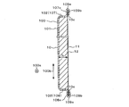
- FIG. 3 is a cross-sectional view of a metal roof material taken along line III-III in FIG. It is a side view of a metal roof material when the area
- FIG. 5 is an explanatory view showing a roofing structure and a roofing method using the metal roof material of FIGS. 1 to 4;
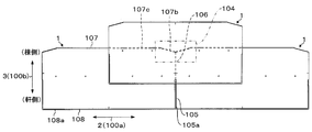
- FIG. 1 is a front view showing a metal roofing material 1 according to Embodiment 1 of the present invention
- FIG. 2 is a rear view showing the metal roofing material 1 of FIG. 1
- FIG. 3 is a line III-III in FIG.
- FIG. 4 is a side view of the metal roofing material 1 when the region IV of FIG. 1 is viewed along the depth direction 100b.
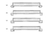
- 5 is an explanatory view showing another aspect of the main body 100 of FIG. 1
- FIG. 6 is an explanatory view showing another aspect of the flange of FIG.
- the metal roofing material 1 shown in FIGS. 1 to 4 is arranged together with other metal roofing materials on the roof foundation of a building such as a house.
- the metal roofing material 1 is fastened to the roof base by driving a fastening member such as a screw or a nail.
- the metal roofing material 1 has a longitudinal direction (a width direction 100a of a main body 100 described later) extending along a direction parallel to the eaves of the roof, and a short direction (a depth direction 100b of the main body 100 described later) is a roof. It is adapted to extend along the direction of the eaves.
- the metal roofing material 1 has a front base material 10, a back base material 11, and a core material 12.
- the front substrate 10 is made of a metal plate, and is a member that appears on the outer surface of the roof when the metal roofing material 1 is placed on the roof base.
- the metal plate that is the material of the front substrate 10 is a hot-dip Zn-plated steel plate, hot-dip Al-plated steel plate, hot-dip Zn-plated stainless steel plate, hot-dip Al-plated stainless steel plate, stainless steel plate, Al plate, Ti plate, and paint-melted Zn-base.
- a plated steel plate, a coated hot-dip Al-plated steel plate, a coated hot-dip Zn-based plated stainless steel plate, a painted hot-Al plated stainless steel plate, a painted stainless steel plate, a painted Al plate, or a coated Ti plate can be used.
- the thickness of the metal plate is preferably 0.27 mm or more and 0.5 mm or less. As the thickness of the metal plate increases, the strength of the roofing material increases while the weight increases. By setting the thickness of the metal plate to 0.27 mm or more, the strength required as a roofing material can be secured, and the wind pressure resistance performance and the crushing performance can be sufficiently obtained.
- the wind pressure resistance is the performance that the metal roofing material 1 can withstand without buckling against strong wind.
- By setting the thickness of the metal plate to 0.5 mm or less it is possible to avoid the weight of the metal roofing material 1 from becoming too large, and to cover equipment such as solar cell modules, solar water heaters, air conditioner outdoor units, snow melting related equipment, etc. The total weight of the roof when placed on top can be reduced.
- the front substrate 10 has a box-shaped main body portion 100 having a top plate portion 101 and a peripheral wall portion 102.
- the main body 100 is preferably formed by drawing or overhanging a metal plate.
- the peripheral wall portion 102 can be a wall surface continuous in the circumferential direction of the front substrate 10, and moisture can enter the inside of the main body portion 100. Can be lowered.
- the peripheral wall 102 is formed by work hardening. Hardness can be increased. Specifically, the Vickers hardness of the peripheral wall portion 102 can be increased by about 1.4 to 1.6 times compared to before processing. As described above, the peripheral wall portion 102 is a wall surface continuous in the circumferential direction of the front substrate 10 and the hardness of the peripheral wall portion 102 is increased by work hardening, so that the wind pressure resistance performance of the metal roofing material 1 is remarkably improved. .
- the back substrate 11 is a member arranged on the back side of the front substrate 10 so as to close the opening of the main body 100.
- a lightweight material such as aluminum foil, aluminum vapor-deposited paper, aluminum hydroxide paper, calcium carbonate paper, resin film or glass fiber paper can be used. By using these lightweight materials for the back substrate 11, it is possible to avoid an increase in the weight of the metal roofing material 1.
- the core material 12 is made of, for example, a foamed resin or the like, and is filled between the main body portion 100 of the front base material 10 and the back base material 11.
- the core material 12 is filled between the main body portion 100 and the back base material 11, so that the core material is placed inside the main body portion 100 rather than an aspect in which a backing material such as a resin sheet is attached to the back side of the front base material 10. 12 can be firmly adhered to each other, and the performance required for the roofing material such as rain sound property, heat insulation property and tread resistance can be improved.
- the height h of the main body 100 filled with the core material 12 is preferably 4 mm or more and 8 mm or less.
- the strength of the main body 100 can be sufficiently increased, and wind resistance can be improved.
- the heat insulation is also good at 4 mm or more.
- the height h of the main body 100 to 8 mm or less, it is possible to avoid the increase in the organic mass of the core material 12 and to obtain the incombustible material certification more reliably.
- the top plate 101 of the main body 100 is provided with a plurality of driving display portions 103 that are spaced apart from each other along the width direction 100 a of the main body 100.
- the driving display unit 103 is a configuration for representing a position at which the binding member is driven into the metal roof material 1.
- the driving display unit 103 according to the present embodiment is configured by a concave portion having a circular shape in plan view.
- the driving display unit 103 may take other modes in which the operator can visually or tactilely recognize the driving position of the binding member, such as a convex portion, an opening, or a printed or engraved symbol.
- a first side surface 105, a second side surface 106, a ridge side end surface 107, and an eaves side end surface 108 are provided on the peripheral wall portion 102 of the main body 100.
- the first and second side surfaces 105 and 106 are provided on both sides of the main body 100 along the width direction 100a.
- the second side surface 106 is adapted to be positioned on the ridge side with respect to the first side surface 105 when the metal roofing material 1 is disposed on the roof base. As shown particularly in FIG. 4, the second side surface 106 is disposed at a position protruding outward from the first side surface 105 along the width direction 100 a of the main body 100.
- a connection wall extending along the width direction 100 a is provided between the first and second side surfaces 105 and 106.
- the connection wall of the present embodiment is configured by an inclined surface that goes outward along the width direction 100a as it approaches the second side surface 106 along the depth direction 100b.
- the connection wall may be configured by a curved surface that extends outward along the width direction 100a as it approaches the second side surface 106 along the wall surface parallel to the width direction 100a or the depth direction 100b.
- the first side surface 105 is formed by folding a metal plate extending outward from the lower end of the first side surface 105 along the width direction 100 a to the back side of the front base material 10 so as to hold the back base material 11.
- a side flange 105a is provided. Since the side flange 105a is provided integrally with the main body 100, the durability (resistance to resistance) of the metal roof material 1 against an external force that tends to warp the metal roof material 1 to the front side or the back side along a straight line along the width direction 100a. Wind pressure performance) is improved.
- the protruding width W1 of the side flange 105a from the first side surface 105 is set to be equal to or less than the protruding width W2 of the second side surface 106 from the first side surface 105 (W1 ⁇ W2). Moreover, it is preferable that the protrusion width W1 of the side flange 105a from the 1st side surface 105 shall be 2 mm or more and 5 mm or less. By setting the protrusion width W1 to be 2 mm or more, the side flange 105a can have sufficient strength, and the warpage of the front base material 10 can be more reliably prevented.
- the entire width of the metal roofing material 1 is about 908 mm, while the protruding width W1 is about 4.5 mm and the protruding width W2 is about 5.0 mm.
- the second side surface 106 is not provided with a flange. This is because the flange extending from the second side surface 106 is cut and removed after the box-shaped main body 100 is formed.
- the ridge side end face 107 is located at one end along the depth direction 100b, and is adapted to be located on the ridge side when the metal roofing material 1 is placed on the roof base.
- the ridge-side end surface 107 is provided with a straight portion 107a and a slant portion 107b.
- the straight line portion 107a extends linearly along the width direction 100a.
- the oblique portion 107b is disposed on both sides of the linear portion 107a so as to connect the linear portion 107a and the second side surface 106.
- the inclined portion 107b is inclined and extended with respect to the straight portion 107a so as to go to the eave side (the other end side along the depth direction 100b) as it approaches the second side surface 106.
- a metal plate extending from the lower end of the ridge-side end surface 107 toward the outside along the depth direction 100 b is attached to the linear portion 107 a of the ridge-side end surface 107.
- a ridge-side flange 107c formed by being folded back on the back side of the front substrate 10 so as to be held is provided. Similar to the side flange 105a described above, the protrusion width of the ridge side flange 107c from the ridge side end surface 107 is preferably 2 mm or more and 5 mm or less.
- the inclined portion 107b of the ridge side end surface 107 is not provided with a flange. This is because the flange extending from the inclined portion 107b is cut and removed after the box-shaped main body portion 100 is formed as in the second side surface 106 described above. However, a flange similar to the ridge side flange 107c may be provided in the oblique portion 107b.
- the eaves side end face 108 is located at the other end along the depth direction 100b, and is adapted to be located on the eave side when the metal roofing material 1 is placed on the roof base.
- the eaves-side end surface 108 is configured only by a straight line portion extending along the width direction 100a.
- the eaves side end surface 108 may have another shape.
- the eaves side end surface 108 is formed by folding a metal plate extending outward from the lower end of the eaves side end surface 108 along the depth direction 100b to the back side of the front substrate 10 so as to hold the back substrate 11.
- An eaves side flange 108a is provided. Similar to the above-described side flange 105a and ridge side flange 107c, the protruding width of the eaves side flange 108a from the eaves side end surface 108 is preferably 2 mm or more and 5 mm or less.
- the ridge side flange 107c and the eaves side flange 108a are extended along the width direction 100a, and prevent the metal roof material 1 from warping along the direction intersecting the width direction 100a.
- the three flanges of the side flange 105a, the ridge side flange 107c, and the eaves side flange 108a are collectively referred to as a flange.
- most of the outer edge 10 c of the metal plate constituting the front substrate 10 constitutes the tip of the flange.
- the outer edge 10c is located inside the side end 109a of the flange.
- the outer edge 10c is often not coated or plated, the outer edge 10c is positioned on the inner side of the side end 109a, so that the outer edge 10c is not subject to external corrosion factors such as rainwater and sea salt particles. Most exposures can be avoided.
- the back end 109b in contact with the roof base is provided at the folded portion of the flange.
- a distance D1 (see FIG. 4) between the back end 109b and the back surface 11a of the back substrate 11 is set to 1 mm or more and 4 mm or less.
- the shape of the folded portion of the flange may be a shape that is folded once by 180 ° bending having a certain curvature as shown in FIGS. 3 and 4, or as shown in FIG. 6 (a). After that, the bending may be further repeated. Further, as shown in FIGS. 6B to 6D, the flange may be folded back by 90 ° bending. Even when the flange is folded back by 90 ° bending or 180 ° bending, the radius of curvature of the bent portion of the metal plate in the flange is preferably 0.5 mm or more.
- the curvature radius By setting the curvature radius to 0.5 mm or more, it is possible to avoid the occurrence of cracks in the coating film and plating layer of the metal plate due to bending, and the occurrence of peeling of the coating film and plating layer and corrosion of the metal plate. it can.
- FIG. 7 is an explanatory view showing a roofing structure and a roofing method using the metal roofing material 1 of FIGS.
- the roofing structure and the roofing method are described using three metal roofing materials 1, but more metal roofing materials 1 are actually used for the roofing structure and the roofing method.
- the plurality of metal roofing materials 1 are arranged on the roof base while the sides of each other are butted.
- each metal roof material 1 since the second side surface 106 is disposed at a position protruding from the first side surface 105, each metal roof material 1 has the second side surface 106 butted against the second side surface 106 of the other metal roof material 1. And placed on the roof base. In this state, the first side surfaces 105 of the metal roofing materials 1 are separated from each other, so that water that has entered between the first side surfaces 105 smoothly flows down to the eaves side.
- the first side surface 105 is provided with the side surface flange 105a. Since the side flange 105a is provided, the strength of the metal roofing material 1 is improved.
- the reason why the protrusion width W1 of the side flange 105a is set to be equal to or less than the protrusion width W2 of the second side face 106 as described with reference to FIG. 4 is to ensure that the second side faces 106 of the metal roofing materials 1 face each other. .
- the protruding width W1 of the side flange 105a is equal to the protruding width W2 of the second side face 106, not only the second side face 106 but also the side flange 105a are abutted.
- the distance D1 between the back end 109b of the side flange 105a and the back surface 11a is 4 mm or less. Therefore, the amount of moisture accumulated between the side flanges 105a can be suppressed. Further, since the metal roofing material 1 is provided with flanges (side flange 105a, ridge side flange 107c, and eaves side flange 108a), a gap is formed between the back base material 11 and the roof base. As a result, the amount of water remaining on the back side of the metal roofing material 1 can be reduced, and the risk of corrosion can be further reduced.
- moisture may enter the ridge side of the metal roofing material 1 due to, for example, strong winds.
- the inclined portion 107b is provided on the ridge side end surface 107, the moisture that has entered the ridge side is guided to the abutting portion of the second side surface 106 by the inclined portion 107b, and the moisture gradually moves toward the eave side through the abutting portion. Can be discharged.
- the plurality of metal roofing materials 1 are arranged on the roof base while the building-side metal roofing material 1 is overlaid on the eaves-side metal roofing material 1.
- the eaves side end portion (the side end 109a of the eaves side flange 108a) of the ridge side metal roofing material 1 is positioned above the first side surface 105 and the side surface flange 105a of the eaves side metal roofing material 1,
- the metal roofing material 1 on the ridge side is overlaid on the metal roofing material 1 on the eaves side.
- an external force such as a strong wind starts from the end of the eaves side of the metal roofing material 1 on the ridge side. Try to warp.
- the ridge-side metal roof is arranged such that the second side face 106 of the ridge-side metal roof material is positioned above the ridge-side end of the eave-side metal roof material 1 (side end 109a of the ridge-side flange 107c).
- the material 1 is stacked on the metal roof material 1 on the eaves side.
- the metal roofing material 1 is piled up, so that the possibility of moisture entering the building side of the eaves-side metal roofing material 1 through the gap between the building-side metal roofing materials 1 is reduced.
- the inventor made a prototype of the metal roofing material 1 as a test material under the following conditions.
- the material of the front substrate 10 was a coated hot-dip Zn-55% Al-plated steel sheet, a painted hot-Zn-6% Al-3% Mg-plated steel sheet, or a painted hot-Al plated steel sheet having a thickness of 0.20 to 0.6 mm.
- As the back substrate 11 0.2 mm glass fiber paper, 0.2 mm Al vapor-deposited paper, 0.2 mm PE resin film, 0.1 mm Al foil or 0.27 mm painted hot-dip Zn plated steel sheet was used.
- the core material 12 a two-component mixed type foamed resin was used. The mixing ratio of the polyol component and the isocyanate, phenol or nurate component was 1: 1 by weight.
- the back base material 11 is arranged on the back side of the front base material 10 so as to close the opening of the main body 100, and a commercially available high-pressure injector is used.
- a foamed resin was injected into the gap between the main body 100 of the front substrate 10 and the back substrate 11. Resin foaming is carried out for 2 minutes in a mold whose temperature is adjusted to 70 ° C by circulating hot water, and then the roofing material is taken out of the mold and allowed to stand at room temperature of 20 ° C for 5 minutes to complete foaming of the resin. It was.
- the flange protrudes from the lower end of the main body 100 toward the outside of the main body 100 so that the projecting width is 5 mm.
- the extending metal plate was cut, and the metal plate was bent into a predetermined shape by a bender.
- the final size of the metal roofing material 1 was 414 mm ⁇ 910 mm.
- the final thickness of the roofing material was in the range of 3 mm to 8 mm.
- the roof material was also prototyped (conventional configuration).
- a 0.2 mm glass fiber paper was used for the back substrate of this metal roofing material.
- the dimension of the roofing material was 6 mm in thickness, and other conditions were the same as those described above.
- a metal roof material not injected with foamed resin a roof material obtained by bonding a commercially available 0.3 mm heat insulating polyethylene sheet to a surface base material processed with an adhesive, a 6 mm thick concrete tile, and a 16 mm thick clay
- a fitting type metal roofing material using a tile and a 0.35 mm-thick painted molten Zn-55% Al alloy-plated steel sheet (without a backing material) was also used for the test.
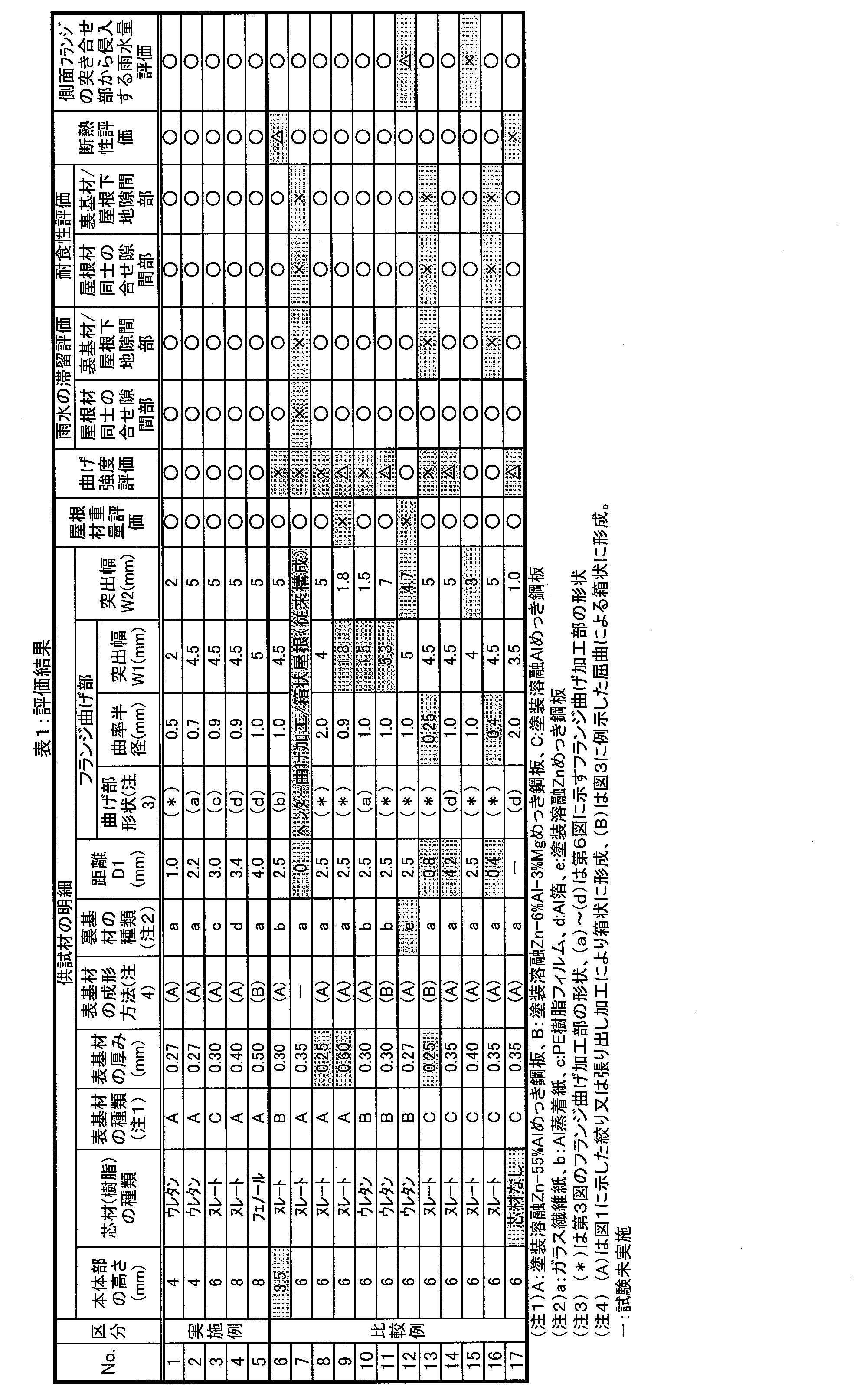
- the present inventors use the above-described test materials to (1) evaluate the weight of the roof material, (2) evaluate the bending strength of the roof material, (3) evaluate the retention of rainwater, and (4) evaluate the corrosion resistance. (5) Evaluation of heat insulation and (6) Evaluation of the amount of rainwater entering the building side from the butt portion of the side flange. The results are shown in the following table.
- Evaluation criteria of roof material weight The weight of the roof material was measured and evaluated according to the following criteria. In addition, this evaluation criteria assumed that a standard 130 N / m 2 solar cell module was mounted on the roof, and evaluated according to the following evaluation criteria from the weight of the entire roof including the roofing material.
- ⁇ The weight of the roofing material is less than 250 N / m 2
- ⁇ The weight of the roofing material is 250 N / m 2 or more
- thermocouple was attached to the surface of the front base material of the simulated roof and the back surface of the base plate where the rainwater retention state was evaluated.
- 12 lamps 100 / 110V, 150W
- a thermocouple at a lamp output of 60%. Insulation was evaluated.
- the heat insulation was evaluated according to the following criteria. ⁇ : The temperature of the back of the base plate is less than 50 ° C.
- X The baseplate back temperature is 55 ° C or higher.
- the amount of rainwater at this time was 4,000 mL / min per 1 m 2 .
- ⁇ Moisture sensitive paper is hardly discolored and there is almost no infiltration of rainwater.
- ⁇ Moisture sensitive paper is slightly discolored and rainwater is slightly infiltrated. Rainwater is infiltrated remarkably
- No. 9 and 10 had a flange protrusion width W1 of less than 2 mm, and the bending strength was insufficient. In No. 11, the protruding width exceeded 5 mm, and the bending strength decreased. From this result, the superiority that the protrusion width of the flange is 2 mm or more and 5 mm or less was confirmed.
- the protrusion width W1 of the 12 and 15 side flanges 105a is equal to or greater than the protrusion width W2 of the second side face 106, the second side faces do not abut each other, and a gap is formed.
- the thickness of the surface base materials of No. 8 and 13 was less than 0.27 mm, the bending strength was insufficient. Moreover, the thickness of the surface base material of No. 9 exceeded 0.5 mm, and the roofing material weight became evaluation of x. From this result, it was confirmed that the thickness of the metal plate constituting the surface base material 10 is 0.27 mm or more and 0.5 mm or less.
- the surface base material 10 is a coated hot-dip Al-plated steel sheet, so that cracks occur in the coating film and the plating layer. Corrosion occurred from the part and the evaluation of corrosion resistance was inferior. From this result, when using the metal plate which has a coating film and a plating layer, the predominance of making the curvature radius of the bent part of a metal plate into 0.5 mm or more was confirmed.
- the thickness of the main body 100 (roof material) of No. 6 was less than 4 mm, and as a result, the bending strength was evaluated as x. Further, the heat insulation performance was slightly lowered, and the evaluation was ⁇ . From this result, the superiority of making the height of the main body portion 100 4 mm or more was confirmed. Although not specifically shown in Table 1, by setting the height of the main body 100 to 8 mm or less, avoiding an excessive increase in the organic mass of the core material 12 and obtaining a nonflammable material certification more reliably. Can do.
- the back base material 11 of No. 12 is a coated hot-dip Zn-plated steel sheet and not lightweight, the roof material weight evaluation was inferior. From this result, the superiority of using a lightweight material such as aluminum foil, aluminum vapor-deposited paper, aluminum hydroxide paper, calcium carbonate paper, resin film or glass fiber paper as the back substrate 11 was confirmed. It was done.
- the present inventors also conducted a wind resistance test of the roof material in accordance with Japanese Industrial Standard A1515. That is, using a dynamic wind pressure test apparatus, the presence or absence of destruction of the specimen when pressurized in the pressurization process was observed.
- a 0.27 mm-thick painted molten Zn-55% Al-plated steel plate and a 0.5-mm thick aluminum plate were used as the material for the surface base material 10.
- the main body part 100 was created by overhanging these materials.
- a glass fiber paper is disposed as the back substrate 11 on the back side of the front substrate 10 so as to close the opening of the main body 100, and a gap between the front substrate 10 and the back substrate 11 is obtained by a commercially available injection machine.
- the nurate resin was injected. Resin foaming was held in a mold whose temperature was adjusted to 70 ° C. by circulating hot water for 2 minutes, and then the roof material was taken out of the mold and allowed to stand at 20 ° C. for 5 minutes to complete foaming of the resin.
- the thickness of the roofing material was 5 mm.
- a metal plate extending from the lower end of the main body portion 100 toward the outside of the main body portion 100 is cut so that the width of the flange is 5 mm, and the metal plate is bent by a bender in FIG.
- the shape was processed into a bent portion width of 3.0 mm, a bending height of 3.0 mm, and a bending radius of 1.0 mm.
- the wind pressure resistance was evaluated based on the breaking pressure at the time of breaking.
- the fracture pressure was negative pressure 6,000 N / m 2 or more.
- burst pressure is negative pressure 5,000 N / m 2 or more 6,000N / m less than 2. That is, it was confirmed that even when an aluminum plate is used, good wind pressure resistance can be obtained, and when a steel plate is used, even better wind pressure resistance can be obtained. It is considered that the work hardening of the peripheral wall portion 102 due to the overhang processing appears more noticeably in the steel plate than in the aluminum plate, and the hardness difference of the peripheral wall portion 102 becomes the difference in the evaluation result of the wind resistance test.
- the second side surface 106 is abutted with the second side surface 106 of the other metal roofing material 1 and disposed on the roof base. Since the metal roofing material 1 is configured as described above, the moisture accumulated between the metal roofing materials 1 can be reduced, and the moisture entering the ridge side of the metal roofing material 1 can be reduced. Moreover, since the side flange 105a is provided on the first side surface 105, the strength of the metal roofing material 1 can be improved.
- the linear portion 107a and the second side surface 106 are arranged on both sides of the linear portion 107a so as to connect to the linear portion 107a so as to approach the eaves side as the second side surface 106 is approached. Since the inclined portion 107b is provided on the ridge side end surface 107, the moisture that has entered the ridge side can be guided to the abutting portion of the second side surface 106 by the oblique portion 107b, and the moisture is evaporated through this abutting portion. Can be gradually discharged to the side.
- the ridge side flange 107c is provided in the linear part 107a of the ridge side end surface 107, the warp of the metal roof material 1 along the direction intersecting the width direction 100a can be reduced.
- the eaves side end face 108 is provided with the eaves side flange 108a, the warp of the metal roofing material 1 along the direction intersecting the width direction 100a can be reduced.
- the flange 108a provided in the linear part of the eaves side end surface 108 becomes a site
- the flange 108a suppresses the generation of this gap and improves the durability (wind pressure resistance).
- the surface rigidity can be increased. Since the force by which the fastened upper roof material presses the lower roof increases, both the upper roof and the lower roof are less likely to be deformed. As a result, durability (wind pressure resistance) is improved. Further, the flanges 107a, 108b and 105a surrounding the four sides of the roofing material improve the flatness of the roofing material itself, and have an effect of suppressing initial warpage and twist, and the gap between the upper and lower roofing materials accompanying them.
- the main body part 100 has the peripheral wall part 102 which consists of the wall surface continuous in the circumferential direction of the front base material 10, possibility that a water
- the protrusion width of the flange (side flange 105a, ridge side flange 107c, and eaves side flange 108a) from the main body 100 is 2 mm or more and 5 mm or less, the flange can have sufficient strength, and metal The design property of the roofing material 1 can be kept favorable.
- the metal plate that is the material of the front substrate 10 is a hot-dip Zn-plated steel plate, hot-dip Al-plated steel plate, hot-melt Zn-plated stainless steel plate, hot-dip Al-plated stainless steel plate, stainless steel plate, Al plate, Ti plate, paint melt Because it consists of Zn-plated steel sheet, painted hot-dip Al-plated steel sheet, painted hot-melted Zn-plated stainless steel sheet, painted hot-plated Al-plated stainless steel sheet, painted stainless steel sheet, painted Al plate or painted Ti plate, it is more reliable for corrosion of metal roofing materials. Fear can be reduced.
- board thickness of the metal plate which comprises the surface base material 10 is 0.27 mm or more and 0.5 mm or less, while fully securing the intensity
- Such a configuration is particularly useful when devices such as a solar cell module, a solar water heater, an air conditioner outdoor unit, and a snow melting related device are provided on the roof.
- the curvature radius of the bent portion of the metal plate included in the flange is 0.5 mm or more, it is possible to avoid the occurrence of cracks in the coating film and the plating layer of the metal plate by bending, and more reliably the metal. Corrosion of the plate can be avoided.
- the height h of the main body 100 is 4 mm or more and 8 mm or less, the nonflammable material certification can be obtained more reliably while ensuring heat insulation and strength.
- the main body part 100 is formed by drawing or overhanging a metal plate, and a hot-dip Zn-plated steel plate, hot-dip Al-plated steel plate, hot-dip Zn-plated stainless steel plate, hot-dip Al-plated stainless steel plate, stainless steel plate , Al plate, Ti plate, Paint hot-dip Zn-plated steel plate, Paint hot-dip Al-plated steel plate, Paint hot-dip Zn-plated stainless steel plate, Paint hot-dip Al-plated stainless steel plate or Painted stainless steel plate, hardness of peripheral wall 102 by work hardening Can be improved, and better wind pressure resistance can be obtained.
- the back substrate 11 is made of aluminum foil, aluminum vapor-deposited paper, aluminum hydroxide paper, calcium carbonate paper, resin film or glass fiber paper, it can be avoided that the weight of the metal roofing material 1 becomes too large.
- the eaves side metal roofing material 1 is located on the eaves side so that the eaves side end of the eaves side metal roofing material 1 is positioned above the first side surface 105 and the side flange 105a of the eaves side metal roofing material 1. Since the metal roofing material 1 is disposed so as to overlap with the metal roofing material 1, it can withstand external force by the relatively strong side flange 105 a, and warpage of the eaves-side metal roofing material 1 can be suppressed.
- the 2nd side surface 106 of the ridge side metal roofing material 1 is located above the ridge side edge part of the eaves side metal roofing material 1, it passes through the clearance gap between the ridge side metal roofing materials 1 and eaves. The possibility of moisture entering the ridge side of the metal roofing material 1 on the side can be reduced.
Landscapes
- Engineering & Computer Science (AREA)
- Architecture (AREA)
- Civil Engineering (AREA)
- Structural Engineering (AREA)
- Mechanical Engineering (AREA)
- Roof Covering Using Slabs Or Stiff Sheets (AREA)
Abstract
Description
実施の形態1.
図1は本発明の実施の形態1による金属屋根材1を示す正面図であり、図2は図1の金属屋根材1を示す背面図であり、図3は図1の線III-IIIに沿う金属屋根材1の断面図であり、図4は図1の領域IVを奥行方向100bに沿って見たときの金属屋根材1の側面図である。また、図5は図1の本体部100の別態様を示す説明図であり、図6は図1のフランジの別態様を示す説明図である。
裏基材11のとしては、0.2mmガラス繊維紙、0.2mmAl蒸着紙、0.2mmPE樹脂フィルム、0.1mmAl箔又は0.27mm塗装溶融Znめっき鋼板を使用した。
芯材12としては、2液混合型の発泡樹脂を使用した。ポリオール成分とイソシアネート、フェノールもしくはヌレート成分の混合比率は重量比で1:1とした。
また、比較のために、発泡樹脂を注入しない金属屋根材、市販の0.3mmの断熱ポリエチレンシートを接着剤により加工した表基材に接着した屋根材、6mm厚みのコンクリート瓦、16mm厚みの粘土瓦、及び0.35mm厚みの塗装溶融Zn-55%Al合金めっき鋼板(裏打ち材なし)を用いた嵌合方式の金属屋根材も試験に供した。
屋根材の単重を計測し、以下の基準により評価した。なお、本評価基準は、標準的な130N/m2の太陽電池モジュールが屋根に搭載されたことを想定し、屋根材を含む屋根全体の重量から以下の評価基準により評価した。
○:屋根材単重が250N/m2未満
×:屋根材単重が250N/m2以上
450mmの間隔を置いて配置した一対の棒状部材の上に棒状部材の延在方向を短手方向として屋根材を置き、棒状部材の位置を支点とし、棒状部材の中間位置を力点としてオートグラフを用いて最大荷重を測定した。
屋根材の曲げ強度は、以下の基準により評価した。
○:最大荷重が160N以上
△:最大荷重が160Nmm未満かつ50N以上
×:最大荷重が50N未満
野地板(厚さ12mm)の表面に市販の防水シートを貼り、傾斜角30°とし、図7に示す重ね葺き施工により屋根材を4段葺いた模擬屋根を作製した。模擬屋根全体に水道水を10分間スプレー噴霧し、全体が十分に濡れるようにした。その次に、室温20℃の恒温室で模擬屋根を5時間静置乾燥した。屋根材と屋根材の棟軒方向(縦つなぎ部)の隙間を目視で観察し乾燥炉状態を評価した。また、屋根材を剥がし、屋根材の裏基材側および防水シート表面の乾燥炉状態を目視で観察し評価した。
乾燥状態は以下の基準で評価した。
○:十分乾燥し殆んど濡れが認められない。
△:僅かな濡れが認められる。
×:乾燥しておらず、濡れが認められる。
重ね葺き施工した屋根を想定して、図7に示す重ね葺き施工により屋根材を3段葺いた模擬屋根を作製した。日本工業規格Z2371に沿う複合サイクル腐食試験(1サイクル:5%塩水噴霧35度,1時間→50℃乾燥4時間→98%RH,50℃湿潤3時間)を200サイクル実施した後、軒と平行な方向2に隣り合う2つの金属屋根材1の突合せ部分の腐食状況を目視で観察した。また、各金属屋根材1の表基材10を剥ぎ取り、表基材10の裏側の腐食状況を観察した。
耐食性は以下の規準により評価した。
○:殆んど腐食が認められない。
△:僅かな腐食が認められる。
×:著しい腐食が認められる。
雨水の滞留状態を評価した模擬屋根の表基材表面及び野地板の裏面に熱電対を取り付けた。この模擬屋根の表面から180mmの位置に12個のランプ(100/110V、150W)を均等に配置し、ランプ出力60%にて照射1時間経過後の野地板裏温度を熱電対によって測定することで断熱性を評価した。
断熱性は、以下の基準により評価した。
○:野地板裏温度が50℃未満。
△:野地板裏温度が50~55℃。
×:野地板裏温度が55℃以上。
上記(3)と同様の方法で摸擬屋根を作成した。この摸擬屋根には図7に示す様に軒側2枚の屋根材と防水シートの間に、syngent社(スイス)製の水感応紙104を挿入した。この水感応紙104は、初期の乾燥状態では黄色を呈し、水に接するとその部分が瞬時に紺青色へと変化する。この変色の程度により、雨水の浸入を以下の基準で評価した。
なお、雨水浸入の程度は、上記摸擬屋根に風速30m/sの環境下で7分間スプレー噴霧し、暴風雨に屋根が晒された状況を摸擬した。この時の雨水量は1m2あたり4,000mL/分とした。
○:水分感応紙が殆ど変色しておらず、雨水の浸入が殆ど無い
△:水分感応紙が僅かな変色が認められ、雨水が僅かに浸入している
×:水分感応紙が著しく変色しており、雨水が著しく浸入している
また、距離D1が4mmを超えるNo.14の場合、曲げ強度が低下するとともに、屋根材同士のあわせ隙間部に雨水が滞留し耐食性が劣った。
この結果から、フランジの裏端109bと裏基材11の裏面との間の距離D1を1mm以上かつ4mm以下とすることの優位性が確認された。
Claims (18)
- 屋根下地の上に他の金属屋根材とともに配置される金属屋根材であって、
金属板を素材とし箱形に形成され本体部を有する表基材と、
前記本体部の開口を塞ぐように前記表基材の裏側に配置された裏基材と、
前記本体部と前記裏基材との間に充填された芯材と
を備え、
前記本体部には、第1側面と、前記屋根下地の上に配置された際に前記第1側面よりも棟側に位置するように適合されるとともに前記第1側面よりも前記本体部の幅方向に沿う外方に突出した位置に配置された第2側面とが設けられており、
前記第1側面には、前記第1側面の下端から前記幅方向に沿う外方に向けて延びる前記金属板が前記裏基材を抱え込むように前記表基材の裏側に折り返されることで形成された側面フランジが設けられており、
前記側面フランジには、前記屋根下地に接する裏端が設けられており、
前記側面フランジの前記裏端と前記裏基材の裏面との間の距離は1mm以上かつ4mm以下とされており、
前記第1側面からの前記側面フランジの突出幅は前記第1側面からの前記第2側面の突出幅以下とされており、少なくとも前記第2側面が他の金属屋根材の第2側面と突き合わされて前記屋根下地の上に配置されるように構成されている、
金属屋根材。 - 前記本体部には、前記屋根下地の上に配置された際に棟側に位置する棟側端面が設けられており、
前記棟側端面には、前記幅方向に沿って延在された直線部と、前記直線部と前記第2側面とを接続するように前記直線部の両側に配置されるとともに、前記第2側面に近づくにつれて軒側に向かうように前記直線部に対して傾斜して延在された斜部とが設けられている、
請求項1記載の金属屋根材。 - 前記棟側端面の前記直線部には、前記棟側端面の下端から前記本体部の奥行方向に沿う外方に向けて延びる前記金属板が前記裏基材を抱え込むように前記表基材の裏側に折り返されることで形成された棟側フランジが設けられており、
前記棟側フランジには、前記屋根下地に接する裏端が設けられており、
前記棟側フランジの前記裏端と前記裏基材の裏面との間の距離は1mm以上かつ4mm以下とされている、
請求項2記載の金属屋根材。 - 前記本体部には、前記屋根下地の上に配置された際に軒側に位置する軒側端面が設けられており、
前記軒側端面には、前記軒側端面の下端から前記本体部の奥行方向に沿う外方に向けて延びる前記金属板が前記裏基材を抱え込むように前記表基材の裏側に折り返されることで形成された軒側フランジが設けられており、
前記軒側フランジには、前記屋根下地に接する裏端が設けられており、
前記軒側フランジの前記裏端と前記裏基材の裏面との間の距離は1mm以上かつ4mm以下とされている、
請求項1から請求項3までのいずれか一項に記載の金属屋根材。 - 前記本体部は、前記表基材の周方向に連続する壁面からなる側壁部を有している、
請求項1から請求項4までのいずれか一項に記載の金属屋根材。 - 前記第1側面からの前記側面フランジの突出幅は、2mm以上かつ5mm以下である、
請求項1から請求項5までのいずれか一項に記載の金属屋根材。 - 前記表基材の素材である前記金属板は、溶融Zn系めっき鋼板、溶融Alめっき鋼板、溶融Zn系めっきステンレス鋼板、溶融Alめっきステンレス鋼板、ステンレス鋼板、Al板、Ti板、塗装溶融Zn系めっき鋼板、塗装溶融Alめっき鋼板、塗装溶融Zn系めっきステンレス鋼板、塗装溶融Alめっきステンレス鋼板、塗装ステンレス鋼板、塗装Al板又は塗装Ti板からなる、
請求項1から請求項6までのいずれか一項に記載の金属屋根材。 - 前記表基材を構成する前記金属板の板厚は0.27mm以上かつ0.5mm以下である、
請求項7記載の金属屋根材。 - 前記側面フランジに含まれる前記金属板の屈曲部は、曲率半径が0.5mm以上とされている、
請求項7又は請求項8に記載の金属屋根材。 - 前記本体部の高さは4mm以上かつ8mm以下とされている、
請求項1から請求項9までのいずれか一項に記載の金属屋根材。 - 前記裏基材は、アルミ箔、アルミ蒸着紙、水酸化アルミ紙、炭酸カルシウム紙、樹脂フィルム又はガラス繊維紙からなる、
請求項1から請求項10までのいずれか一項に記載の金属屋根材。 - 請求項5記載の金属屋根材を製造するための金属屋根材製造方法であって、
前記表基材の素材である前記金属板は、溶融Zn系めっき鋼板、溶融Alめっき鋼板、溶融Zn系めっきステンレス鋼板、溶融Alめっきステンレス鋼板、ステンレス鋼板、Al板、Ti板、塗装溶融Zn系めっき鋼板、塗装溶融Alめっき鋼板、塗装溶融Zn系めっきステンレス鋼板、塗装溶融Alめっきステンレス鋼板又は塗装ステンレス鋼板からなり、
前記金属板に絞り加工又は張り出し加工を施すことで前記本体部を形成すること
を含む、金属屋根材製造方法。 - 金属板を素材とし箱形に形成され本体部を有する表基材と、
前記本体部の開口を塞ぐように前記表基材の裏側に配置された裏基材と、
前記本体部と前記裏基材との間に充填された芯材と
をそれぞれ有し、
前記本体部には、第1側面と、前記屋根下地の上に配置された際に前記第1側面よりも棟側に位置するように適合されるとともに前記第1側面よりも前記本体部の幅方向に沿う外方に突出した位置に配置された第2側面とが設けられており、
前記第1側面には、前記第1側面の下端から前記幅方向に沿う外方に向けて延びる前記金属板が前記裏基材を抱え込むように前記表基材の裏側に折り返されることで形成された側面フランジが設けられており、
前記側面フランジには、前記屋根下地に接する裏端が設けられており、
前記側面フランジの前記裏端と前記裏基材の裏面との間の距離は1mm以上かつ4mm以下とされており、
前記第1側面からの前記側面フランジの突出幅は前記第1側面からの前記第2側面の突出幅以下とされている
複数の金属屋根材を備え、
少なくとも互いの前記第2側面を突き合わせながら前記複数の金属屋根材が屋根下地の上に配置されている、
屋根葺き構造。 - 棟側の前記金属屋根材の軒側端部が軒側の前記金属屋根材の前記第1側面及び前記側面フランジの上方に位置するように、棟側の前記金属屋根材が軒側の前記金属屋根材に重ねて配置されている、
請求項13記載の屋根葺き構造。 - 軒側の前記金属屋根材の棟側端部の上方に棟側の前記金属屋根材の前記第2側面が位置されている、
請求項14記載の屋根葺き構造。 - 金属板を素材とし箱形に形成され本体部を有する表基材と、
前記本体部の開口を塞ぐように前記表基材の裏側に配置された裏基材と、
前記本体部と前記裏基材との間に充填された芯材と
をそれぞれ有し、
前記本体部には、第1側面と、前記屋根下地の上に配置された際に前記第1側面よりも棟側に位置するように適合されるとともに前記第1側面よりも前記本体部の幅方向に沿う外方に突出した位置に配置された第2側面とが設けられており、
前記第1側面には、前記第1側面の下端から前記幅方向に沿う外方に向けて延びる前記金属板が前記裏基材を抱え込むように前記表基材の裏側に折り返されることで形成された側面フランジが設けられており、
前記側面フランジには、前記屋根下地に接する裏端が設けられており、
前記側面フランジの前記裏端と前記裏基材の裏面との間の距離は1mm以上かつ4mm以下とされており、
前記第1側面からの前記側面フランジの突出幅は前記第1側面からの前記第2側面の突出幅以下とされている
複数の金属屋根材を用いた屋根葺き方法であって、
少なくとも互いの前記第2側面を突き合わせながら前記複数の金属屋根材を屋根下地の上に配置すること
を含む、
屋根葺き方法。 - 棟側の前記金属屋根材の軒側端部が軒側の前記金属屋根材の前記第1側面及び前記側面フランジの上方に位置するように、棟側の前記金属屋根材を軒側の前記金属屋根材に重ねて配置すること
をさらに含む、
請求項16記載の屋根葺き方法。 - 棟側の前記金属屋根材を軒側の前記金属屋根材に重ねて配置する際、軒側の前記金属屋根材の棟側端部の上方に棟側の前記金属屋根材の前記第2側面を位置させる、
請求項17記載の屋根葺き方法。
Priority Applications (7)
| Application Number | Priority Date | Filing Date | Title |
|---|---|---|---|
| AU2016360048A AU2016360048B2 (en) | 2015-11-27 | 2016-03-24 | Metal roofing material, and roofing structure and roofing method using same |
| KR1020187018242A KR101980061B1 (ko) | 2015-11-27 | 2016-03-24 | 금속 지붕재 및 그것을 이용한 지붕 이음 구조 및 지붕 이음 방법 |
| EA201890871A EA036580B1 (ru) | 2015-11-27 | 2016-03-24 | Металлический кровельный материал, кровельная конструкция и способ выполнения кровли с их использованием |
| EP16868208.6A EP3382121B1 (en) | 2015-11-27 | 2016-03-24 | Metal roofing member, roofing structure, production method of such metal roofing member and roofing method |
| CN201680069135.0A CN108474209B (zh) | 2015-11-27 | 2016-03-24 | 金属屋顶构材和使用该构材的屋顶铺盖构造及铺盖方法 |
| US15/778,100 US10597874B2 (en) | 2015-11-27 | 2016-03-24 | Metal roofing material, and roofing structure and roofing method using same |
| MYPI2018701625A MY172376A (en) | 2015-11-27 | 2016-03-24 | Metal roofing material, and roofing structure and roofing method using same |
Applications Claiming Priority (2)
| Application Number | Priority Date | Filing Date | Title |
|---|---|---|---|
| JP2015-231569 | 2015-11-27 | ||
| JP2015231569A JP5999824B1 (ja) | 2015-11-27 | 2015-11-27 | 金属屋根材並びにそれを用いた屋根葺き構造及び屋根葺き方法 |
Publications (1)
| Publication Number | Publication Date |
|---|---|
| WO2017090257A1 true WO2017090257A1 (ja) | 2017-06-01 |
Family
ID=56997672
Family Applications (1)
| Application Number | Title | Priority Date | Filing Date |
|---|---|---|---|
| PCT/JP2016/059384 Ceased WO2017090257A1 (ja) | 2015-11-27 | 2016-03-24 | 金属屋根材並びにそれを用いた屋根葺き構造及び屋根葺き方法 |
Country Status (10)
| Country | Link |
|---|---|
| US (1) | US10597874B2 (ja) |
| EP (1) | EP3382121B1 (ja) |
| JP (1) | JP5999824B1 (ja) |
| KR (1) | KR101980061B1 (ja) |
| CN (1) | CN108474209B (ja) |
| AU (1) | AU2016360048B2 (ja) |
| EA (1) | EA036580B1 (ja) |
| MY (1) | MY172376A (ja) |
| TW (1) | TWI720069B (ja) |
| WO (1) | WO2017090257A1 (ja) |
Cited By (1)
| Publication number | Priority date | Publication date | Assignee | Title |
|---|---|---|---|---|
| EP3690164A4 (en) * | 2017-09-28 | 2021-06-09 | Nippon Steel Corporation | METAL WALL MATERIAL AND WALL CONSTRUCTION PROCESS WITH IT |
Families Citing this family (4)
| Publication number | Priority date | Publication date | Assignee | Title |
|---|---|---|---|---|
| EA201992465A1 (ru) | 2017-05-23 | 2020-05-08 | Ниппон Стил Ниссин Ко., Лтд. | Металлический кровельный материал и способ выполнения кровли с применением упомянутого материала |
| JP2019065622A (ja) * | 2017-10-03 | 2019-04-25 | 日新製鋼株式会社 | 金属屋根材の製造方法 |
| CA3083230A1 (en) * | 2017-11-24 | 2019-05-31 | Bluescope Steel Limited | Wall panel / roof panel |
| CN111321849B (zh) * | 2018-12-14 | 2025-11-11 | 东君新能源有限公司 | 一种用于瓦片安装的固定装置及具有其的可拆卸瓦片 |
Citations (3)
| Publication number | Priority date | Publication date | Assignee | Title |
|---|---|---|---|---|
| JPH10306548A (ja) * | 1997-05-09 | 1998-11-17 | Takehiko Kimura | 金属屋根板とその金属屋根板の係合方法 |
| JP2003074147A (ja) | 2001-09-03 | 2003-03-12 | Sekisui Chem Co Ltd | 金属製屋根材 |
| JP2003074163A (ja) * | 2001-09-04 | 2003-03-12 | Munemasu Shirota | 外装材 |
Family Cites Families (60)
| Publication number | Priority date | Publication date | Assignee | Title |
|---|---|---|---|---|
| US157392A (en) * | 1874-12-01 | Improvement in roofing-tiles | ||
| US460283A (en) * | 1891-09-29 | Metallic ceiling | ||
| US1519350A (en) * | 1922-05-27 | 1924-12-16 | George A Belding | Metal shingle |
| US2065478A (en) * | 1935-11-18 | 1936-12-22 | Schulman Joseph | Roof construction |
| US2882840A (en) * | 1956-02-01 | 1959-04-21 | George F Waske | Shingle construction |
| US2961804A (en) * | 1957-12-16 | 1960-11-29 | Globe Roofing Products Co Inc | Metallic surfaced siding and roofing material |
| US3312031A (en) * | 1966-04-04 | 1967-04-04 | Kaiser Aluminium Chem Corp | Shingle structure with reentrant joint configurations and a nailing tab |
| US3394515A (en) * | 1968-01-02 | 1968-07-30 | Elwin G Smith & Company Inc | Roofing and siding panel construction |
| US3667184A (en) * | 1970-02-24 | 1972-06-06 | Clifford C Merrill | Interlocking metal shingle construction |
| US3760546A (en) * | 1971-08-24 | 1973-09-25 | Holiday Recreation Prod Inc | Modular roof construction |
| CA1042177A (en) * | 1976-05-06 | 1978-11-14 | Louis L. Vallee | Metal roofing shingle |
| US4244353A (en) * | 1977-04-07 | 1981-01-13 | Straza George T | Solar heating shingle roof structure |
| CA1071826A (en) * | 1977-12-14 | 1980-02-19 | Louis L. Vallee | Metal shingle roof modern design |
| US4445305A (en) * | 1982-09-27 | 1984-05-01 | Orie Sr Thomas A | Insulating secondary roof system |
| CN1005870B (zh) * | 1986-06-17 | 1989-11-22 | 松下电器产业株式会社 | 潜热蓄热装置 |
| FR2608964B1 (fr) * | 1986-12-24 | 1989-10-20 | Saint Gobain Isover | Panneaux composites moules |
| SE459761B (sv) * | 1987-12-07 | 1989-07-31 | Nordisk Plaatformning Ab | Beklaednadselement |
| JPH01158165A (ja) | 1987-12-15 | 1989-06-21 | Ig Tech Res Inc | 金属パネル |
| US5442888A (en) * | 1992-12-08 | 1995-08-22 | Ilnyckyj; Peter | Shingles |
| CN2152761Y (zh) * | 1993-03-10 | 1994-01-12 | 赖忠喜 | 金属浪板 |
| US5349801A (en) * | 1993-08-25 | 1994-09-27 | Aluminum Company Of America | Sheet metal shingle |
| US5469680A (en) * | 1994-03-18 | 1995-11-28 | Revere Copper Products, Inc. | Metal roofing system |
| WO1995026451A1 (en) * | 1994-03-25 | 1995-10-05 | Plath Construction, Inc. | Metal shingle |
| US5495654A (en) * | 1994-04-08 | 1996-03-05 | Weirton Steel Corporation | Preparing sheet metal and fabricating roofing shingles |
| US5625999A (en) * | 1994-08-23 | 1997-05-06 | International Paper Company | Fiberglass sandwich panel |
| US5685117A (en) * | 1995-04-13 | 1997-11-11 | Nicholson; Joseph R. | Shingle system and fastening strip |
| US5784848A (en) * | 1996-11-05 | 1998-07-28 | Toscano; Philip | Roofing system and shingle |
| US5799460A (en) * | 1997-02-27 | 1998-09-01 | Brian Dary | Method of shingling a roof and interlocking roofing system |
| US5711127A (en) * | 1997-03-05 | 1998-01-27 | Sabourin; Brunelle P. | Roof shingle |
| US5842315A (en) * | 1997-03-24 | 1998-12-01 | Tung Yik Trading Co., Ltd. | Corrugated board structure |
| US6173546B1 (en) * | 1998-08-28 | 2001-01-16 | James P Schafer | Interlocking metal shingle |
| JP3388208B2 (ja) * | 1999-09-21 | 2003-03-17 | 宗勉 城田 | 屋根葺材 |
| CA2331166A1 (en) * | 2001-01-16 | 2002-07-16 | Pierre Tremblay | Metal roofing shingle |
| JP2002309752A (ja) | 2001-04-18 | 2002-10-23 | Sekisui Chem Co Ltd | 壁パネルおよびその製造方法 |
| US6883290B2 (en) * | 2002-02-20 | 2005-04-26 | Powerlight Corporation | Shingle system and method |
| US6708463B2 (en) * | 2002-02-25 | 2004-03-23 | King T. Chai | Method and apparatus for repairing roof covering |
| US7178301B2 (en) * | 2002-10-25 | 2007-02-20 | Albright Gary T | Simulated wood roofing shake |
| KR200327057Y1 (ko) * | 2003-06-26 | 2003-09-19 | (주)로자 | 건축물 내외장용 거멀접기형 패널 |
| JP3709485B1 (ja) * | 2004-10-08 | 2005-10-26 | 株式会社昭和 | ライニング構造 |
| JP2006257783A (ja) * | 2005-03-18 | 2006-09-28 | Tiger Vacuum Bottle Co Ltd | 屋根瓦 |
| CA2610464A1 (en) * | 2005-06-13 | 2006-12-21 | Kingspan Research And Developments Limited | A roof panel |
| US8191326B2 (en) * | 2005-06-24 | 2012-06-05 | American Metal Ceiling Panel Manufacturing, Inc. | Decorative room panel |
| ITMI20051199A1 (it) * | 2005-06-24 | 2006-12-25 | Intersider Acciai S P A | Piastrella per rivestimenti in metallo metodo per la produzione e rivestimenti relativi |
| CN200958265Y (zh) * | 2006-03-31 | 2007-10-10 | 桑永明 | 一种房屋用复合板 |
| US20100186334A1 (en) * | 2009-01-27 | 2010-07-29 | Seem Charles T | Metal roofing shingle, metal roofing shingle system, and method of installing |
| WO2011149706A1 (en) * | 2010-05-27 | 2011-12-01 | Dow Global Technologies Llc | Method of manufacturing a shaped foam article |
| NZ592562A (en) * | 2011-04-29 | 2013-11-29 | Edward Lawrence Noton | An Improved Roof Tile |
| CA2876992A1 (en) * | 2011-08-16 | 2013-02-16 | Joseph Robert Nicholson | Roof element |
| WO2013054571A1 (ja) * | 2011-10-13 | 2013-04-18 | 日鉄住金鋼板株式会社 | 建築用パネル及び建築用パネルの下地材への取付構造 |
| JP5898461B2 (ja) * | 2011-11-02 | 2016-04-06 | 日鉄住金鋼板株式会社 | 屋根材 |
| US8898963B1 (en) * | 2011-11-03 | 2014-12-02 | Certainteed Corporation | Roofing shingles with reduced usage of conventional shingle material and having a combination vertical and lateral lap extension |
| EP2749707B1 (en) * | 2012-12-27 | 2017-06-14 | VKR Holding A/S | A skirt member for use in a flashing for a roof penetrating structure and use of a skirt member in flashing a roof window mounted in an inclined roof |
| US9598857B2 (en) * | 2013-01-14 | 2017-03-21 | Nanopore, Inc. | Thermal insulation products for insulating buildings and other enclosed environments |
| JP5785242B2 (ja) * | 2013-09-30 | 2015-09-24 | 日鉄住金鋼板株式会社 | 屋根材及び屋根構造 |
| CN204112610U (zh) * | 2014-01-26 | 2015-01-21 | 广东华途仕建材实业有限公司 | 一种新型的金属屋面板 |
| US9322173B2 (en) * | 2014-02-05 | 2016-04-26 | Michael Pisani | Lightweight shingle assembly |
| JP6362563B2 (ja) * | 2015-03-27 | 2018-07-25 | 日新製鋼株式会社 | 金属屋根材及びその製造方法並びに屋根葺き構造及び屋根葺き方法 |
| JP5864015B1 (ja) * | 2015-03-27 | 2016-02-17 | 日新製鋼株式会社 | 金属屋根材、それを用いた屋根葺き構造及び屋根葺き方法並びに金属屋根材製造方法 |
| JP6110973B1 (ja) * | 2015-10-02 | 2017-04-05 | 日新製鋼株式会社 | 金属屋根材及び屋根葺き方法 |
| MY188170A (en) * | 2015-10-02 | 2021-11-24 | Nisshin Steel Co Ltd | Metal roofing material and roofing method |
-
2015
- 2015-11-27 JP JP2015231569A patent/JP5999824B1/ja not_active Expired - Fee Related
-
2016
- 2016-03-24 CN CN201680069135.0A patent/CN108474209B/zh not_active Expired - Fee Related
- 2016-03-24 EP EP16868208.6A patent/EP3382121B1/en not_active Not-in-force
- 2016-03-24 EA EA201890871A patent/EA036580B1/ru not_active IP Right Cessation
- 2016-03-24 WO PCT/JP2016/059384 patent/WO2017090257A1/ja not_active Ceased
- 2016-03-24 KR KR1020187018242A patent/KR101980061B1/ko not_active Expired - Fee Related
- 2016-03-24 MY MYPI2018701625A patent/MY172376A/en unknown
- 2016-03-24 AU AU2016360048A patent/AU2016360048B2/en not_active Ceased
- 2016-03-24 US US15/778,100 patent/US10597874B2/en active Active
- 2016-11-25 TW TW105138852A patent/TWI720069B/zh not_active IP Right Cessation
Patent Citations (3)
| Publication number | Priority date | Publication date | Assignee | Title |
|---|---|---|---|---|
| JPH10306548A (ja) * | 1997-05-09 | 1998-11-17 | Takehiko Kimura | 金属屋根板とその金属屋根板の係合方法 |
| JP2003074147A (ja) | 2001-09-03 | 2003-03-12 | Sekisui Chem Co Ltd | 金属製屋根材 |
| JP2003074163A (ja) * | 2001-09-04 | 2003-03-12 | Munemasu Shirota | 外装材 |
Non-Patent Citations (1)
| Title |
|---|
| See also references of EP3382121A4 |
Cited By (1)
| Publication number | Priority date | Publication date | Assignee | Title |
|---|---|---|---|---|
| EP3690164A4 (en) * | 2017-09-28 | 2021-06-09 | Nippon Steel Corporation | METAL WALL MATERIAL AND WALL CONSTRUCTION PROCESS WITH IT |
Also Published As
| Publication number | Publication date |
|---|---|
| JP5999824B1 (ja) | 2016-09-28 |
| CN108474209A (zh) | 2018-08-31 |
| EP3382121A1 (en) | 2018-10-03 |
| AU2016360048A1 (en) | 2018-05-17 |
| KR101980061B1 (ko) | 2019-05-17 |
| EA201890871A1 (ru) | 2018-09-28 |
| CN108474209B (zh) | 2019-10-29 |
| US20190264448A1 (en) | 2019-08-29 |
| EA036580B1 (ru) | 2020-11-25 |
| AU2016360048B2 (en) | 2019-06-27 |
| TWI720069B (zh) | 2021-03-01 |
| TW201723284A (zh) | 2017-07-01 |
| EP3382121B1 (en) | 2020-04-22 |
| US10597874B2 (en) | 2020-03-24 |
| MY172376A (en) | 2019-11-21 |
| KR20180079456A (ko) | 2018-07-10 |
| EP3382121A4 (en) | 2018-12-05 |
| JP2017096048A (ja) | 2017-06-01 |
Similar Documents
| Publication | Publication Date | Title |
|---|---|---|
| JP5864015B1 (ja) | 金属屋根材、それを用いた屋根葺き構造及び屋根葺き方法並びに金属屋根材製造方法 | |
| JP5999824B1 (ja) | 金属屋根材並びにそれを用いた屋根葺き構造及び屋根葺き方法 | |
| US5295340A (en) | Dimensional shingle for hip, ridge and rake portions of a roof | |
| GB2460762A (en) | Composite insulating panel with solar collector | |
| WO2018216105A1 (ja) | 金属屋根材及びそれを用いた屋根葺き方法 | |
| JP6479922B1 (ja) | 屋根の補修方法及びその屋根構造 | |
| JP6035667B1 (ja) | 屋外用遮熱材及び屋外遮熱構造 | |
| TW201802330A (zh) | 金屬屋頂構件 | |
| JP6362563B2 (ja) | 金属屋根材及びその製造方法並びに屋根葺き構造及び屋根葺き方法 | |
| JP6378237B2 (ja) | 金属屋根材及びそれを用いた屋根葺き方法 | |
| JP6545328B2 (ja) | 金属屋根材及びその製造方法並びに屋根葺き構造及び屋根葺き方法 | |
| JP2021195816A (ja) | 凹凸屋根の遮熱構造 | |
| JP2007009655A (ja) | 断熱瓦とその製造方法および屋根構造 | |
| JPH045638Y2 (ja) | ||
| JP2017066834A (ja) | 金属屋根材及びそれを用いた屋根葺き方法 | |
| JP2024098658A (ja) | 板状屋根材 | |
| DK201670221A1 (da) | Fremgangsmåde til etablering af en skotrende samt en skotrende | |
| PL220165B1 (pl) | Płyta absorbera solarnego z tworzywa polimerowego | |
| GB2459734A (en) | Corrugated flashing suitable for roof joints with offset adjoining columns |
Legal Events
| Date | Code | Title | Description |
|---|---|---|---|
| 121 | Ep: the epo has been informed by wipo that ep was designated in this application |
Ref document number: 16868208 Country of ref document: EP Kind code of ref document: A1 |
|
| WWE | Wipo information: entry into national phase |
Ref document number: 201890871 Country of ref document: EA |
|
| ENP | Entry into the national phase |
Ref document number: 2016360048 Country of ref document: AU Date of ref document: 20160324 Kind code of ref document: A |
|
| NENP | Non-entry into the national phase |
Ref country code: DE |
|
| ENP | Entry into the national phase |
Ref document number: 20187018242 Country of ref document: KR Kind code of ref document: A |
|
| WWE | Wipo information: entry into national phase |
Ref document number: 2016868208 Country of ref document: EP |