WO2017090338A1 - 液体ブロー成形方法 - Google Patents
液体ブロー成形方法 Download PDFInfo
- Publication number
- WO2017090338A1 WO2017090338A1 PCT/JP2016/080731 JP2016080731W WO2017090338A1 WO 2017090338 A1 WO2017090338 A1 WO 2017090338A1 JP 2016080731 W JP2016080731 W JP 2016080731W WO 2017090338 A1 WO2017090338 A1 WO 2017090338A1
- Authority
- WO
- WIPO (PCT)
- Prior art keywords
- liquid
- preform
- blow molding
- molding
- pressure
- Prior art date
- Legal status (The legal status is an assumption and is not a legal conclusion. Google has not performed a legal analysis and makes no representation as to the accuracy of the status listed.)
- Ceased
Links
Images
Classifications
-
- B—PERFORMING OPERATIONS; TRANSPORTING
- B29—WORKING OF PLASTICS; WORKING OF SUBSTANCES IN A PLASTIC STATE IN GENERAL
- B29C—SHAPING OR JOINING OF PLASTICS; SHAPING OF MATERIAL IN A PLASTIC STATE, NOT OTHERWISE PROVIDED FOR; AFTER-TREATMENT OF THE SHAPED PRODUCTS, e.g. REPAIRING
- B29C49/00—Blow-moulding, i.e. blowing a preform or parison to a desired shape within a mould; Apparatus therefor
- B29C49/42—Component parts, details or accessories; Auxiliary operations
- B29C49/46—Component parts, details or accessories; Auxiliary operations characterised by using particular environment or blow fluids other than air
-
- B—PERFORMING OPERATIONS; TRANSPORTING
- B29—WORKING OF PLASTICS; WORKING OF SUBSTANCES IN A PLASTIC STATE IN GENERAL
- B29C—SHAPING OR JOINING OF PLASTICS; SHAPING OF MATERIAL IN A PLASTIC STATE, NOT OTHERWISE PROVIDED FOR; AFTER-TREATMENT OF THE SHAPED PRODUCTS, e.g. REPAIRING
- B29C49/00—Blow-moulding, i.e. blowing a preform or parison to a desired shape within a mould; Apparatus therefor
- B29C49/08—Biaxial stretching during blow-moulding
- B29C49/10—Biaxial stretching during blow-moulding using mechanical means for prestretching
- B29C49/12—Stretching rods
-
- B—PERFORMING OPERATIONS; TRANSPORTING
- B29—WORKING OF PLASTICS; WORKING OF SUBSTANCES IN A PLASTIC STATE IN GENERAL
- B29C—SHAPING OR JOINING OF PLASTICS; SHAPING OF MATERIAL IN A PLASTIC STATE, NOT OTHERWISE PROVIDED FOR; AFTER-TREATMENT OF THE SHAPED PRODUCTS, e.g. REPAIRING
- B29C49/00—Blow-moulding, i.e. blowing a preform or parison to a desired shape within a mould; Apparatus therefor
- B29C49/18—Blow-moulding, i.e. blowing a preform or parison to a desired shape within a mould; Apparatus therefor using several blowing steps
-
- B—PERFORMING OPERATIONS; TRANSPORTING
- B29—WORKING OF PLASTICS; WORKING OF SUBSTANCES IN A PLASTIC STATE IN GENERAL
- B29C—SHAPING OR JOINING OF PLASTICS; SHAPING OF MATERIAL IN A PLASTIC STATE, NOT OTHERWISE PROVIDED FOR; AFTER-TREATMENT OF THE SHAPED PRODUCTS, e.g. REPAIRING
- B29C49/00—Blow-moulding, i.e. blowing a preform or parison to a desired shape within a mould; Apparatus therefor
- B29C49/28—Blow-moulding apparatus
-
- B—PERFORMING OPERATIONS; TRANSPORTING
- B29—WORKING OF PLASTICS; WORKING OF SUBSTANCES IN A PLASTIC STATE IN GENERAL
- B29C—SHAPING OR JOINING OF PLASTICS; SHAPING OF MATERIAL IN A PLASTIC STATE, NOT OTHERWISE PROVIDED FOR; AFTER-TREATMENT OF THE SHAPED PRODUCTS, e.g. REPAIRING
- B29C49/00—Blow-moulding, i.e. blowing a preform or parison to a desired shape within a mould; Apparatus therefor
- B29C49/42—Component parts, details or accessories; Auxiliary operations
- B29C49/4268—Auxiliary operations during the blow-moulding operation
-
- B—PERFORMING OPERATIONS; TRANSPORTING
- B29—WORKING OF PLASTICS; WORKING OF SUBSTANCES IN A PLASTIC STATE IN GENERAL
- B29C—SHAPING OR JOINING OF PLASTICS; SHAPING OF MATERIAL IN A PLASTIC STATE, NOT OTHERWISE PROVIDED FOR; AFTER-TREATMENT OF THE SHAPED PRODUCTS, e.g. REPAIRING
- B29C49/00—Blow-moulding, i.e. blowing a preform or parison to a desired shape within a mould; Apparatus therefor
- B29C49/42—Component parts, details or accessories; Auxiliary operations
- B29C49/4289—Valve constructions or configurations, e.g. arranged to reduce blowing fluid consumption
-
- B—PERFORMING OPERATIONS; TRANSPORTING
- B29—WORKING OF PLASTICS; WORKING OF SUBSTANCES IN A PLASTIC STATE IN GENERAL
- B29C—SHAPING OR JOINING OF PLASTICS; SHAPING OF MATERIAL IN A PLASTIC STATE, NOT OTHERWISE PROVIDED FOR; AFTER-TREATMENT OF THE SHAPED PRODUCTS, e.g. REPAIRING
- B29C49/00—Blow-moulding, i.e. blowing a preform or parison to a desired shape within a mould; Apparatus therefor
- B29C49/42—Component parts, details or accessories; Auxiliary operations
- B29C49/64—Heating or cooling preforms, parisons or blown articles
- B29C49/66—Cooling by refrigerant introduced into the blown article
-
- B—PERFORMING OPERATIONS; TRANSPORTING
- B29—WORKING OF PLASTICS; WORKING OF SUBSTANCES IN A PLASTIC STATE IN GENERAL
- B29C—SHAPING OR JOINING OF PLASTICS; SHAPING OF MATERIAL IN A PLASTIC STATE, NOT OTHERWISE PROVIDED FOR; AFTER-TREATMENT OF THE SHAPED PRODUCTS, e.g. REPAIRING
- B29C49/00—Blow-moulding, i.e. blowing a preform or parison to a desired shape within a mould; Apparatus therefor
- B29C49/42—Component parts, details or accessories; Auxiliary operations
- B29C49/46—Component parts, details or accessories; Auxiliary operations characterised by using particular environment or blow fluids other than air
- B29C2049/4602—Blowing fluids
- B29C2049/465—Blowing fluids being incompressible
- B29C2049/4655—Blowing fluids being incompressible water
-
- B—PERFORMING OPERATIONS; TRANSPORTING
- B29—WORKING OF PLASTICS; WORKING OF SUBSTANCES IN A PLASTIC STATE IN GENERAL
- B29C—SHAPING OR JOINING OF PLASTICS; SHAPING OF MATERIAL IN A PLASTIC STATE, NOT OTHERWISE PROVIDED FOR; AFTER-TREATMENT OF THE SHAPED PRODUCTS, e.g. REPAIRING
- B29C49/00—Blow-moulding, i.e. blowing a preform or parison to a desired shape within a mould; Apparatus therefor
- B29C49/42—Component parts, details or accessories; Auxiliary operations
- B29C49/46—Component parts, details or accessories; Auxiliary operations characterised by using particular environment or blow fluids other than air
- B29C2049/4602—Blowing fluids
- B29C2049/465—Blowing fluids being incompressible
- B29C2049/4658—Blowing fluids being incompressible oil
-
- B—PERFORMING OPERATIONS; TRANSPORTING
- B29—WORKING OF PLASTICS; WORKING OF SUBSTANCES IN A PLASTIC STATE IN GENERAL
- B29C—SHAPING OR JOINING OF PLASTICS; SHAPING OF MATERIAL IN A PLASTIC STATE, NOT OTHERWISE PROVIDED FOR; AFTER-TREATMENT OF THE SHAPED PRODUCTS, e.g. REPAIRING
- B29C49/00—Blow-moulding, i.e. blowing a preform or parison to a desired shape within a mould; Apparatus therefor
- B29C49/42—Component parts, details or accessories; Auxiliary operations
- B29C49/46—Component parts, details or accessories; Auxiliary operations characterised by using particular environment or blow fluids other than air
- B29C2049/4602—Blowing fluids
- B29C2049/465—Blowing fluids being incompressible
- B29C2049/4664—Blowing fluids being incompressible staying in the final article
-
- B—PERFORMING OPERATIONS; TRANSPORTING
- B29—WORKING OF PLASTICS; WORKING OF SUBSTANCES IN A PLASTIC STATE IN GENERAL
- B29C—SHAPING OR JOINING OF PLASTICS; SHAPING OF MATERIAL IN A PLASTIC STATE, NOT OTHERWISE PROVIDED FOR; AFTER-TREATMENT OF THE SHAPED PRODUCTS, e.g. REPAIRING
- B29C49/00—Blow-moulding, i.e. blowing a preform or parison to a desired shape within a mould; Apparatus therefor
- B29C49/42—Component parts, details or accessories; Auxiliary operations
- B29C49/58—Blowing means
- B29C2049/5841—Plural independent blowing paths
-
- B—PERFORMING OPERATIONS; TRANSPORTING
- B29—WORKING OF PLASTICS; WORKING OF SUBSTANCES IN A PLASTIC STATE IN GENERAL
- B29C—SHAPING OR JOINING OF PLASTICS; SHAPING OF MATERIAL IN A PLASTIC STATE, NOT OTHERWISE PROVIDED FOR; AFTER-TREATMENT OF THE SHAPED PRODUCTS, e.g. REPAIRING
- B29C49/00—Blow-moulding, i.e. blowing a preform or parison to a desired shape within a mould; Apparatus therefor
- B29C49/42—Component parts, details or accessories; Auxiliary operations
- B29C49/42403—Purging or cleaning the blow-moulding apparatus
-
- B—PERFORMING OPERATIONS; TRANSPORTING
- B29—WORKING OF PLASTICS; WORKING OF SUBSTANCES IN A PLASTIC STATE IN GENERAL
- B29K—INDEXING SCHEME ASSOCIATED WITH SUBCLASSES B29B, B29C OR B29D, RELATING TO MOULDING MATERIALS OR TO MATERIALS FOR MOULDS, REINFORCEMENTS, FILLERS OR PREFORMED PARTS, e.g. INSERTS
- B29K2023/00—Use of polyalkenes or derivatives thereof as moulding material
- B29K2023/10—Polymers of propylene
- B29K2023/12—PP, i.e. polypropylene
-
- B—PERFORMING OPERATIONS; TRANSPORTING
- B29—WORKING OF PLASTICS; WORKING OF SUBSTANCES IN A PLASTIC STATE IN GENERAL
- B29K—INDEXING SCHEME ASSOCIATED WITH SUBCLASSES B29B, B29C OR B29D, RELATING TO MOULDING MATERIALS OR TO MATERIALS FOR MOULDS, REINFORCEMENTS, FILLERS OR PREFORMED PARTS, e.g. INSERTS
- B29K2067/00—Use of polyesters or derivatives thereof, as moulding material
- B29K2067/003—PET, i.e. poylethylene terephthalate
-
- B—PERFORMING OPERATIONS; TRANSPORTING
- B29—WORKING OF PLASTICS; WORKING OF SUBSTANCES IN A PLASTIC STATE IN GENERAL
- B29L—INDEXING SCHEME ASSOCIATED WITH SUBCLASS B29C, RELATING TO PARTICULAR ARTICLES
- B29L2031/00—Other particular articles
- B29L2031/712—Containers; Packaging elements or accessories, Packages
- B29L2031/7158—Bottles
Definitions
- the present invention relates to a liquid blow molding method for forming a container containing a liquid containing a content liquid from a bottomed cylindrical preform, and in particular, a mixed liquid obtained by mixing a first liquid and a second liquid is stored as the content liquid.
- the present invention relates to a liquid blow molding method for molding a container containing liquid.
- Resin containers such as polypropylene (PP) bottles and polyethylene terephthalate (PET) bottles contain various liquids such as beverages, cosmetics, chemicals, detergents, toiletries such as shampoos, etc. It is used for applications.
- PP polypropylene
- PET polyethylene terephthalate
- Such a container is generally manufactured by blow-molding a preform formed into a bottomed cylindrical shape with the above-described resin material having thermoplasticity.
- blow molding for forming a preform into a container liquid blow molding in which a pressurized liquid is used as a pressurizing medium supplied to the inside of the preform is known.
- Patent Document 1 a preform that has been heated to a temperature at which stretchability is developed is set in a mold for blow molding, and the preform is pressurized to a predetermined pressure through a nozzle.
- a liquid blow molding method is described in which a preform is formed into a container having a predetermined shape along a cavity of a mold by supplying a liquid.
- the container is molded and the content liquid in the container is transferred. Since the container containing liquid can be easily formed by filling the liquid at the same time, the filling process of the liquid into the container after molding is omitted, and its production process and production line (device) The configuration can be simplified.
- liquid blow molding is performed by supplying a pressurized liquid into the preform heated to a temperature at which stretchability is developed.
- the component may be denatured, such as denaturation or deactivation, due to the heat of the preform, which makes it difficult to apply.
- the component may be denatured, such as denaturation or deactivation, due to the heat of the preform, which makes it difficult to apply.
- the component may be denatured, such as denaturation or deactivation, due to the heat of the preform, which makes it difficult to apply.
- the component may be denatured, such as denaturation or deactivation
- a liquid that is difficult to maintain in a homogeneous mixed state such as a seasoning dressing in which a liquid mainly composed of oil and a liquid mainly composed of water is mixed is used.
- the container to be accommodated also has a problem that it is difficult to apply the liquid because it is difficult to supply the liquid into the preform through the nozzle while maintaining a homogeneous mixed state.
- This invention is made
- the objective is difficult to maintain the shaping
- the liquid blow molding method of the present invention is a liquid blow molding method for molding a container containing a liquid containing a content liquid from a bottomed cylindrical preform, and a nozzle is provided inside the preform heated to a predetermined temperature.
- a first molding step of supplying a first liquid at a predetermined pressure through the liquid and blow-molding the preform to an intermediate shape and after the first molding step, a first pressure is introduced into the preform through the nozzle at a predetermined pressure.
- the second molding step it is preferable to supply the first liquid together with the second liquid to the inside of the preform at a predetermined pressure.
- the pressure of the first liquid supplied to the preform is made higher than the pressure inside the preform subjected to liquid blow molding.
- the pressure of the second liquid supplied to the preform is preferably the same as or higher than the pressure of the first liquid supplied to the preform.
- the preform is liquid blow molded. Accordingly, it is preferable to have a cleaning step of removing the second liquid from the inside of the nozzle.
- the liquid blow molding method of the present invention has a circulation step of circulating the first liquid between a tank capable of storing the first liquid and the nozzle before the first molding step in the above configuration. preferable.
- a liquid container containing a liquid containing two kinds of liquids that is difficult to maintain in a homogeneous mixed state or molding of a liquid containing a liquid containing a heat-sensitive component can be provided.
- the liquid blow molding method of the present invention is a liquid blow molding method for molding a container containing a liquid containing a content liquid from a bottomed cylindrical preform, and the nozzle is passed through the preform heated to a predetermined temperature. Supplying the first liquid at a predetermined pressure to perform a liquid blow molding of the preform to an intermediate shape, and supplying the second liquid at a predetermined pressure through the nozzle into the preform after the first molding process And a second molding step of subjecting the preform to liquid blow molding. That is, in the liquid blow molding method of the present invention, when the content liquid stored in the molded liquid container is a mixed liquid obtained by mixing the first liquid and the second liquid, first, only the first liquid is used. Liquid blow molding is performed by supplying the preform, and then liquid blow molding is performed by supplying the second liquid to the preform.
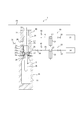
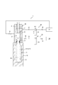
- the liquid blow molding method of the present invention can be performed using, for example, the liquid blow molding apparatus 1 having the configuration shown in FIG.
- a liquid blow molding apparatus 1 shown in FIG. 1 is for molding a preform 2 into a liquid-containing container containing a content liquid therein by liquid blow molding.
- the liquid blow molding is a blow molding performed using a pressurized liquid instead of the pressurized air used in air blow molding as a pressurized medium (pressurized fluid) supplied to the preform 2. It is.
- the liquid L supplied to the preform 2, that is, the content liquid L contained in the molded liquid container, is a mixed liquid obtained by mixing the first liquid L1 and the second liquid L2.
- the first liquid L1 it is preferable to use a liquid that does not easily cause alteration such as denaturation or deactivation (not including a component that changes due to heat).
- a liquid containing components can be used.
- the case where an enzyme-containing liquid detergent is used as the content liquid L is shown.
- the first liquid L1 is a liquid that does not contain an enzyme (a liquid that is resistant to heat)
- the second liquid L2 is a liquid that contains an enzyme (a liquid that is weak against heat). Note that the liquid components that are the basis of the first liquid L1 and the second liquid L2 may be common or different.
- liquid L liquid mixture which mixed the 1st liquid L1 strong against heat and the 2nd liquid L2 weak against heat
- liquid L liquid mixture which mixed the 1st liquid L1 strong against heat and the 2nd liquid L2 weak against heat
- various liquids can be used.
- the liquid L supplied to the preform 2 is not limited to the mixed liquid obtained by mixing the first liquid L1 that is resistant to heat and the second liquid L2 that is vulnerable to heat as described above.
- liquid blow molding such as seasoning dressing in which the liquid (first liquid) and the liquid (second liquid) having a property of easily separating water from oil as a main component are mixed. It is also possible to use a liquid that is difficult to maintain in a mixed state.
- a cylindrical mouth portion 2 a serving as an open end and a lower end of the mouth portion 2 a are blocked by a thermoplastic resin material such as polypropylene (PP) or polyethylene terephthalate (PET).
- PP polypropylene
- PET polyethylene terephthalate
- the preform 2 is not limited to the shape described above, and various shapes can be used according to the shape of the molded container and the like as long as it has a bottomed cylindrical shape.
- an engaging projection for mounting a closing cap (not shown) on the mouth 2a of the molded liquid container by a stopper (undercut engagement) is provided on the outer wall surface of the mouth 2a. Is provided. In addition, it can also be set as the structure which replaces with an engagement protrusion on the outer wall surface of the opening part 2a, and provides an obstruction
- the liquid blow molding apparatus 1 has a mold 10 for blow molding.
- the mold 10 has a cavity 11 having a shape corresponding to the final shape of the container such as a bottle shape.
- the cavity 11 opens upward on the upper surface of the mold 10.
- the preform 2 is mounted on the mold 10 with the body 2b disposed inside the cavity 11 of the mold 10 and the mouth 2a protruding upward from the mold 10.
- the mold 10 can be opened to the left and right. After the preform 2 is molded into a liquid container, the mold 10 is opened to the left and right to open the liquid container. It can be taken out from the mold 10.
- a nozzle unit 20 that functions as a nozzle for supplying a liquid to the inside of the preform 2 is provided above the mold 10.
- the nozzle unit 20 has a main body block 21, and the main body block 21 is movable relative to the mold 10 in the vertical direction.
- a support block 21 a is provided at the lower end of the main body block 21, and a blow nozzle 22 is attached to the lower end of the main body block 21 supported by the support block 21 a.
- the blow nozzle 22 is formed in a substantially cylindrical shape, and engages with the mouth portion 2a of the preform 2 attached to the mold 10 from above when the main body block 21 is lowered to the lower stroke end.
- a conical seal surface 22a is provided on the upper surface of the blow nozzle 22 so as to incline in a reduced diameter as it goes downward.
- a supply path 23 extending in the vertical direction is provided inside the main body block 21.
- the supply path 23 is a flow path for supplying the first liquid L1 and the second liquid L2 to the blow nozzle 22, and communicates with the blow nozzle 22 at the lower end thereof.
- the main body block 21 has a first supply port 24 communicating with the upper end of the supply path 23, a second supply port 25 communicating with the lower end side of the supply path 23, and a circulation port 26 communicating with an intermediate portion of the supply path 23. Is provided.
- a seal body 27 for opening and closing the blow nozzle 22 is disposed inside the supply path 23.
- the seal body 27 is fixed to a lower end of a shaft body 28 provided in the nozzle unit 20 so as to be movable in the vertical direction, and is movable in the vertical direction inside the supply path 23.
- the seal body 27 is formed in a cylindrical shape, and the outer peripheral edge portion of the lower end surface thereof is a tapered contact surface 27a.
- the contact surface 27a has the same inclination angle as the seal surface 22a of the blow nozzle 22 so that the contact surface 27a comes into close contact with the seal surface 22a when the seal body 27 moves to the closed position which is the lower stroke end position. It has become.
- the blow nozzle 22 is closed by the seal body 27, and communication between the blow nozzle 22 and the supply path 23 is blocked.
- the seal body 27 moves upward from the closed position, the blow nozzle 22 is opened and communicated with the supply path 23.
- the liquid blow molding apparatus 1 can be configured to include a stretching rod 29.
- a stretching rod 29 it is possible to perform biaxial stretching blow molding in which the preform 2 is stretched in the radial direction by the pressurized liquid supplied from the mouth portion 2 a while being stretched in the axial direction by the stretching rod 29.
- the liquid blow molding apparatus 1 can be configured not to include the stretching rod 29.
- the first liquid supply unit 30 is connected to the first supply port 24 by a first pipe P1.
- the first liquid supply unit 30 includes a first tank 31 and a first pressure source 32 connected to the downstream side of the first tank 31.
- the first tank 31 may contain the first liquid L1 and may be configured to be able to heat the first liquid L1 to a predetermined temperature and maintain the temperature.
- the first pressurizing source 32 can suck the first liquid L1 accommodated in the first tank 31 and pressurizes the sucked first liquid L1 to a predetermined pressure, via the first supply port 24. It can be supplied to the supply path 23.
- the second liquid supply unit 33 is connected to the second supply port 25 by a second pipe P2.
- the second liquid supply unit 33 includes a second tank 34 and a second pressure source 35 connected to the downstream side of the second tank 34.
- the second tank 34 contains the second liquid L2.
- the second pressurizing source 35 can suck the second liquid L2 accommodated in the second tank 34 and pressurizes the sucked second liquid L2 to a predetermined pressure, via the second supply port 25. It can be supplied to the supply path 23.
- the first pressurizing source 32 and the second pressurizing source 35 are each constituted by a plunger pump.
- the first pressurizing source 32 and the second pressurizing source 35 are not limited to the plunger pump, but the first liquid L1 stored in the first tank 31 or the second tank 34 stored in the second tank 34.
- the liquid L2 can be pressurized to a predetermined pressure and supplied to the supply path 23, it can be configured by a pressure source having another configuration.
- the circulation port 26 is connected to the first tank 31 by a circulation pipe P3, and returns the first liquid L1 supplied from the first pressure source 32 to the supply path 23 to the first tank 31 through the circulation pipe P3. Can be done.
- the first tank 31 has a circulation function, and in a standby state where liquid blow molding is not performed, the first tank 31 and the supply path 23 are not retained in the supply path 23 without retaining the first liquid L1. Between the first tank 31 and the nozzle unit 20.
- a first on-off valve 36 is provided between the first tank 31 and the first pressurizing source 32, and a second on-off valve 37 is provided between the second tank 34 and the second pressurizing source 35. Yes.
- a third on-off valve 38 is provided between the second pressurizing source 35 and the second supply port 25.
- a circulation control on-off valve 39 is provided between the circulation port 26 and the first tank 31.
- a first pressure gauge 40 is provided in the first pipe P1
- a second pressure gauge 41 is provided in the second pipe P2.
- the measurement data of these pressure gauges 40 and 41 is input to a control means (not shown).
- the control means (not shown) is also connected to the first liquid supply section 30 and the second liquid supply section 33, and the operation of the liquid blow molding apparatus 1 is integrally controlled by the control means.
- a preform 2 that has been preliminarily heated to a predetermined temperature (for example, 80 ° C. to 150 ° C.) that exhibits stretchability by using a heating means (not shown) such as a heater is used. Attach to 10 and clamp. Then, the nozzle unit 20 is lowered, and the blow nozzle 22 is engaged with the mouth 2 a of the preform 2.
- a predetermined temperature for example, 80 ° C. to 150 ° C.
- the first on-off valve 36 is opened and the first pressure source 32 is pulled while the seal body 27 is closed, and the first pressure source 32 is accommodated in the first tank 31.
- the first liquid source L1 is sucked into the first pressurizing source 32 to fill the first pressurizing source 32 with the first liquid L1
- the second on-off valve 37 is opened, the third on-off valve 38 is closed, and the second pressure is applied.
- the pressure source 35 is pulled to cause the second liquid L2 contained in the second tank 34 to be sucked into the second pressure source 35 and filled with the second liquid.
- the liquid blow molding apparatus 1 is in a standby state until liquid blow molding is performed in this state.
- the liquid blow molding method of the present invention can be configured to perform a circulation step in the standby state. That is, in the standby state, the first liquid L1 is circulated between the first tank 31 and the nozzle unit 20 by the circulation function of the first tank 31 by opening the circulation control on-off valve 39. it can. Thus, in the standby state until liquid blow molding is performed, the first liquid L1 adjusted to a predetermined temperature by the first tank 31 is always supplied without causing the first liquid L1 to stay in the supply path 23. By circulating through the passage 23, the temperature of the first liquid L1 in the supply passage 23 can be maintained at a predetermined temperature suitable for liquid blow molding.
- liquid blow molding is performed.
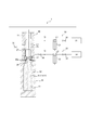
- liquid blow molding is performed by dividing it into a first molding step and a second molding step.
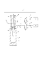
- the first on-off valve 36, the second on-off valve 37, the third on-off valve 38 and the circulation control on-off valve 39 are all closed and the seal body 27 is opened.
- the first pressure source 32 is activated.
- the second pressure source 35 remains stopped.
- the preform 2 heated to a predetermined temperature from the first pressure source 32 through the first pipe P1, the first supply port 24, the supply path 23, and the blow nozzle 22 has a predetermined height higher than that of the cavity 11.
- the preform 2 can be liquid blow molded by supplying only the first liquid L1 having a predetermined temperature pressurized to a pressure.
- the preform 2 is not molded into a complete container shape along the cavity 11, but is molded into a halfway shape.
- the stretching rod 29 is moved downward before the first molding step or in the first molding step, and the preform 2 is stretched in the longitudinal direction by the stretching rod 29.
- the second molding process is performed.
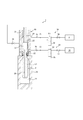
- the first on-off valve 36, the second on-off valve 37, and the circulation control on-off valve 39 are all closed, and the third on-off valve 38 and the seal body 27 are opened.
- the second pressure source 35 is operated.
- the second liquid L2 pressurized to a predetermined pressure is supplied to the inside of the preform 2 molded to a halfway shape through the blow nozzle 22, and the preform 2 is supplied with 2 of the first liquid L1 and the second liquid L2.
- Liquid blow molding can be performed with the liquid L mixed with the liquid.
- the pressure PR2 of the second liquid L2 measured by the second pressure gauge 41 is the same as the pressure PR1 of the first liquid L1 measured by the first pressure gauge 40 or the first liquid L1.
- the pressure is higher than the pressure PR1.
- the pressure PR1 of the first liquid L1 supplied to the inside of the preform 2 is higher than the pressure PR3 inside the preform 2 subjected to liquid blow molding.
- the preform 2 can be stretched in the longitudinal direction by the stretching rod 29 by continuously moving the stretching rod 29 in the second molding step.
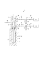
- the liquid blow molding method of the present invention can be configured to perform a cleaning process after the second molding process.
- the preform 2 is not formed into a complete container shape along the cavity 11 but is formed into an intermediate shape.
- the first on-off valve 36, the second on-off valve 37, the third on-off valve 38, and the circulation control on-off valve 39 are all closed and the seal body 27 is opened. Then, the operation of the second pressure source 35 is stopped, and only the first pressure source 32 is operated. Thereby, only the 1st liquid L1 can be supplied to the preform 2 shape
- the second liquid remaining in the supply path 23 in the second molding process when the next preform 2 is liquid blow molded Preventing L2 from being supplied to the preform 2 heated to a predetermined temperature in the new first molding step, and preventing alteration of the content liquid caused by heating the second liquid L2. Can do.
- the preform 2 can be stretched in the longitudinal direction by the stretching rod 29 by continuously moving the stretching rod 29 downward in the cleaning process.
- the sealing body 27 is closed and the liquid blow molding is completed.
- the preform 2 is molded into a liquid container 50 containing the content liquid L in which the first liquid L1 and the second liquid L2 are mixed inside a container having a predetermined shape.
- the liquid level of the content liquid L stored in the liquid container 50 after molding that is, the amount of the content liquid L, is set to an appropriate amount by extracting the stretching rod 29 from the inside of the content liquid L.
- a cap is attached to the mouth portion 50a of the molded liquid container 50, and the mold 10 is then opened to take out the completed liquid container 50 from the mold 10. The cap may be attached after the liquid container 50 is taken out of the mold 10.
- the liquid blow molding apparatus 1 opens the first on-off valve 36 and pulls the first pressurizing source 32 as shown in FIG.
- the first pressurizing source 32 is filled with the first liquid L1
- the second on-off valve 37 is opened
- the third on-off valve 38 is closed
- the second pressurizing source 35 is pulled to move the second pressurizing source 35 to the second pressurizing source 35.
- 2 liquid L2 is filled and it is set as the standby state in preparation for the next liquid blow molding.
- the liquid blow molding method of the present invention only the first liquid L1 is supplied to the preform 2 and the preform 2 is liquid blow molded to an intermediate shape, and then the second liquid L2 is applied to the preform 2. Since the liquid blow molding is performed, the container 50 containing the liquid containing the first liquid L1 and the second liquid L2 containing a heat-sensitive component as the content liquid L is molded. However, after the preform 2 heated to a predetermined temperature is cooled by the first liquid L1, the second liquid L2 is supplied to the preform 2 so that the component contained in the second liquid L2 It can be prevented from being deteriorated by being heated by heat. Therefore, the quality of the content liquid L accommodated in the container 50 with a liquid after shaping
- molding is securable. That is, by using the liquid blow molding method of the present invention, the liquid blow container 50 can be easily applied by applying the liquid blow molding to the liquid fill container 50 containing the content liquid L containing the heat-sensitive component. It can be manufactured.
- liquid blow molding is performed by supplying not only the second liquid L2 but also the first liquid L1 to the preform 2 in addition to the second liquid L2. This eliminates the need for an on-off valve or control for stopping the supply of the first liquid L1, and allows the preform 2 to be formed by liquid blow molding into a liquid container 50 with a simpler and simpler configuration. .
- the first liquid L1 and the heat that do not contain a heat-sensitive component like the enzyme-containing liquid detergent in the present embodiment are mixed.
- a liquid containing oil as a main component and a liquid having a property of easily separating water from oil as a main component are mixed.
- a liquid that is difficult to maintain the first liquid and the second liquid in a mixed state such as a seasoning dressing.
- liquid blow molding apparatus of the present invention is performed using the liquid blow molding apparatus 1 having the configuration shown in FIG.
- the liquid blow molding method of the invention can also be performed.
- the circulation process and the cleaning process are performed in addition to the first molding process and the second molding process.
- a configuration in which these processes are not performed may be employed.
- a suck back process may be performed after the cleaning process, that is, after the preform 2 is liquid blow molded into a container having a predetermined shape.
- the suck-back process can be performed, for example, by sucking out a predetermined amount of the content liquid L filled into the liquid container 50 from the suction port provided at the tip of the stretching rod 29.
- the first liquid L1 is also supplied to the preform 2 in addition to the second liquid L2, and the liquid blow molding is performed.
- the operation of the first pressurizing source 32 is stopped, or the on-off valve provided in the first pipe P1 is closed to completely stop the supply of the first liquid L1, and the second liquid L2 You may make it supply only.
- the preform 2 is liquid blow molded to an intermediate shape in the first molding step.
- the present invention is not limited to this, and the first liquid L1 is applied to the preform 2 in the first molding step. Is filled to form a container having a predetermined shape, and a predetermined head space is formed inside the container by pulling out the suck back and the stretching rod 29 before the second molding process. You may make it supply the 2nd liquid L2 below this head space amount inside.
Landscapes
- Engineering & Computer Science (AREA)
- Manufacturing & Machinery (AREA)
- Mechanical Engineering (AREA)
- Physics & Mathematics (AREA)
- Thermal Sciences (AREA)
- Blow-Moulding Or Thermoforming Of Plastics Or The Like (AREA)
Abstract
有底筒状のプリフォーム(2)から内容液(L)を収容した液体入り容器(50)を成形する液体ブロー成形方法であって、所定の温度にまで加熱したプリフォーム(2)の内部にノズルユニット(20)を通して所定圧力で第1液(L1)を供給して該プリフォーム(2)を途中形状にまで液体ブロー成形する第1成形工程と、第1成形工程の後に、ノズルユニット(20)を通してプリフォーム(2)の内部に所定圧力で第2液(L2)を供給して該プリフォーム(2)を液体ブロー成形する第2成形工程と、を有することを特徴とする液体ブロー成形方法。
Description
本発明は、有底筒状のプリフォームから内容液を収容した液体入り容器を成形する液体ブロー成形方法に関し、特に、内容液として第1液と第2液とを混合した混合液を収容する液体入り容器を成形する液体ブロー成形方法に関する。
ポリプロピレン(PP)製のボトルやポリエチレンテレフタレート(PET)製のボトルに代表されるような樹脂製の容器は、飲料、化粧品、薬品、洗剤、シャンプー等のトイレタリーなどの様々な液体を内容液として収容する用途に使用されている。このような容器は、上記したような熱可塑性を有する樹脂材料によって有底筒状に形成されたプリフォームをブロー成形することにより製造されるのが一般的である。
プリフォームを容器に成形するブロー成形としては、プリフォームの内部に供給する加圧媒体として加圧した液体を用いるようにした液体ブロー成形が知られている。
例えば特許文献1には、予め延伸性を発現する温度にまで加熱しておいたプリフォームをブロー成形用の金型にセットし、このプリフォームの内部にノズルを通して所定の圧力にまで加圧された液体を供給することにより、プリフォームを金型のキャビティに沿った所定形状の容器に成形するようにした液体ブロー成形方法が記載されている。このような液体ブロー成形方法によれば、プリフォームに供給する液体として飲料等の最終的に製品として容器に収容される内容液を使用することにより、容器の成形と当該容器への内容液の充填とを同時に行って、内容液を収容した液体入り容器を容易に成形することができるので、成形後の容器への内容液の充填工程を省略して、その生産工程や生産ライン(装置)の構成を簡略化することができる。
しかしながら、上記従来の液体ブロー成形方法では、延伸性を発現する温度にまで加熱したプリフォームの内部に加圧した液体を供給して液体ブロー成形を行うようにしているので、熱に弱い成分を含んだ液体を内容液として収容する液体入り容器に対しては、当該成分がプリフォームの熱により変性や失活等の変質を生じる虞があることから、その適用が困難であるという問題点があった。例えば、前記成分として酵素入りの液体洗剤を内容液として収容する液体入り容器を成形する場合では、加熱されたプリフォームの内部に当該液体洗剤を供給すると、プリフォームの熱によって液体洗剤に含まれる酵素が変性または失活(変質)してしまい、消費者が使用する際に所定の効用が得られなくなるおそれがある。
また、上記従来の液体ブロー成形方法では、例えば、油分を主成分とした液体と水分を主成分とした液体とを混合した調味用ドレッシングなどの均質な混合状態に維持することが困難な液体を収容する容器に対しても、当該液体を均質な混合状態に維持したままノズルを通してプリフォーム内に供給することが難しいことから、その適用が困難であるという問題点があった。
本発明は、このような課題に鑑みてなされたものであり、その目的は、熱に弱い成分を含んだ内容液を収容する液体入り容器の成形や均質な混合状態に維持することが困難な2種類の液体を含む内容液を収容する液体入り容器の成形にも適用可能な液体ブロー成形方法を提供することにある。
本発明の液体ブロー成形方法は、有底筒状のプリフォームから内容液を収容した液体入り容器を成形する液体ブロー成形方法であって、所定の温度にまで加熱した前記プリフォームの内部にノズルを通して所定圧力で第1液を供給して該プリフォームを途中形状にまで液体ブロー成形する第1成形工程と、前記第1成形工程の後に、前記ノズルを通して前記プリフォームの内部に所定圧力で第2液を供給して該プリフォームを液体ブロー成形する第2成形工程と、を有することを特徴とする。
本発明の液体ブロー成形方法は、上記構成において、前記第2成形工程において、前記プリフォームの内部に所定圧力で前記第2液とともに前記第1液を供給するのが好ましい。
本発明の液体ブロー成形方法は、上記構成において、前記第2成形工程において、前記プリフォームへ供給する前記第1液の圧力を液体ブロー成形された前記プリフォームの内部の圧力よりも高くするとともに、前記プリフォームへ供給する前記第2液の圧力を前記プリフォームへ供給する前記第1液の圧力と同一または該圧力よりも高くするのが好ましい。
本発明の液体ブロー成形方法は、上記構成において、前記第2成形工程の後に、前記ノズルを通して前記プリフォームの内部に所定圧力で前記第1液のみを供給して該プリフォームを液体ブロー成形することにより、前記ノズルの内部から前記第2液を除去するクリーニング工程を有するのが好ましい。
本発明の液体ブロー成形方法は、上記構成において、前記第1成形工程の前に、第1液を収容可能なタンクと前記ノズルとの間で前記第1液を循環させる循環工程を有するのが好ましい。
本発明によれば、熱に弱い成分を含んだ内容液を収容する液体入り容器の成形や均質な混合状態に維持することが困難な2種類の液体を含む内容液を収容する液体入り容器の成形にも適用可能な液体ブロー成形方法を提供することができる。
以下、図面を参照して本発明をより具体的に例示説明する。
本発明の液体ブロー成形方法は、有底筒状のプリフォームから内容液を収容した液体入り容器を成形する液体ブロー成形方法であって、所定の温度にまで加熱したプリフォームの内部にノズルを通して所定圧力で第1液を供給して該プリフォームを途中形状にまで液体ブロー成形する第1成形工程と、第1成形工程の後に、ノズルを通してプリフォームの内部に所定圧力で第2液を供給して該プリフォームを液体ブロー成形する第2成形工程と、を有することを特徴とするものである。すなわち、本発明の液体ブロー成形方法は、成形後の液体入り容器に収容される内容液が第1液と第2液とを混合した混合液である場合において、まず初めに第1液のみをプリフォームに供給して液体ブロー成形を行い、次いで、第2液をプリフォームに供給して液体ブロー成形を行うようにしたものである。本発明の液体ブロー成形方法は、例えば図1に示す構成の液体ブロー成形装置1を用いて実施することができる。
図1に示す液体ブロー成形装置1は、プリフォーム2を液体ブロー成形することにより、内部に内容液を収容した液体入り容器に成形するものである。なお、液体ブロー成形とは、プリフォーム2に供給する加圧媒体(加圧流体)として、エアブロー成形の際に用いられる加圧エアーに替えて、加圧した液体を用いて行うブロー成形のことである。
プリフォーム2に供給される液体L、つまり成形後の液体入り容器に収容される内容液Lは、第1液L1と第2液L2とを混合した混合液である。第1液L1としては熱による変性や失活等の変質を生じづらいもの(熱により変質する成分を含まないもの)を用いるのが好ましく、一方、第2液L2としては熱による変質を生じ易い成分を含む液体を用いることができる。本実施の形態においては、内容液Lとして酵素入り液体洗剤を用いた場合を示す。この場合、第1液L1は酵素を含まない液体(熱に強い液体)であり、第2液L2は酵素を含む液体(熱に弱い液体)である。なお、第1液L1と第2液L2の基本となる液体成分を共通としても、異ならせてもよい。
なお、熱に強い第1液L1と熱に弱い第2液L2とを混合した混合液(液体L)としては、上記した酵素入り液体洗剤に限らず、種々の液体を用いることができる。
また、プリフォーム2に供給される液体Lとしては、上記のような熱に強い第1液L1と熱に弱い第2液L2とを混合した混合液に限らず、例えば、油分を主成分とした液体(第1液)と、水分を主成分として油分に対して容易に分離する性質を有する液体(第2液)とを混合した調味用ドレッシングなど、液体ブロー成形を行うに際して、第1液と第2液とを混合状態に維持しておくことが困難な液体を用いることもできる。
プリフォーム2としては、例えばポリプロピレン(PP)やポリエチレンテレフタレート(PET)等の熱可塑性を有する樹脂材料によって、開口端となる円筒状の口部2aと、口部2aに連なるとともに下端が閉塞された円筒状の胴部2bとを有する有底筒状に形成されたものが用いられる。なお、図中においては、便宜上、胴部2bをその肉厚を省略して記載している。
プリフォーム2としては、上記形状のものに限らず、有底筒状であれば、成形後の容器の形状等に応じて種々の形状のものを用いることができる。
詳細は図示しないが、口部2aの外壁面には、成形後の液体入り容器の口部2aに閉塞キャップ(不図示)を打栓(アンダーカット係合)によって装着するための係合突起が設けられている。なお、口部2aの外壁面に係合突起に替えて雄ネジを設けて閉塞キャップを口部2aにねじ結合により装着する構成とすることもできる。
液体ブロー成形装置1は、ブロー成形用の金型10を有している。この金型10は、例えばボトル形状などの容器の最終形状に対応した形状のキャビティ11を有している。キャビティ11は金型10の上面において上方に向けて開口している。プリフォーム2は、胴部2bが金型10のキャビティ11の内部に配置されるとともに口部2aが金型10から上方に突出した状態となって金型10に装着される。
詳細は図示しないが、金型10は左右に型開きすることができるようになっており、プリフォーム2を液体入り容器に成形した後に金型10を左右に開くことで、当該液体入り容器を金型10から取り出すことができる。
金型10の上方には、プリフォーム2の内部に液体を供給するためのノズルとして機能するノズルユニット20が設けられている。ノズルユニット20は本体ブロック21を有し、この本体ブロック21は金型10に対して上下方向に相対移動自在となっている。本体ブロック21の下端には支持ブロック21aが設けられ、この支持ブロック21aにより支持されて本体ブロック21の下端にはブローノズル22が装着されている。ブローノズル22は略円筒状に形成されており、本体ブロック21が下方側のストローク端にまで下降したときに金型10に装着されたプリフォーム2の口部2aに上方側から係合する。また、ブローノズル22の上面には、下方に向かうに連れて縮径状に傾斜する円錐面状のシール面22aが設けられている。
本体ブロック21の内部には上下方向に延びる供給路23が設けられている。この供給路23はブローノズル22に第1液L1や第2液L2を供給するための流路であり、その下端においてブローノズル22に連通している。また、本体ブロック21には、供給路23の上端に連通する第1供給ポート24、供給路23の下端側に連通する第2供給ポート25及び供給路23の中間部分に連通する循環用ポート26が設けられている。
供給路23の内部にはブローノズル22を開閉するためのシール体27が配置されている。シール体27はノズルユニット20に上下方向に移動自在に設けられた軸体28の下端に固定され、供給路23の内部で上下方向に移動自在となっている。シール体27は円柱状に形成され、その下端面の外周縁部はテーパー状の当接面27aとなっている。当接面27aは、ブローノズル22のシール面22aと同一の傾斜角度を有しており、シール体27が下方側のストローク端位置である閉位置にまで移動するとシール面22aに密着するようになっている。したがって、シール体27が閉位置となると、当該シール体27によってブローノズル22が閉塞され、ブローノズル22と供給路23との間の連通が遮断される。一方、シール体27が閉位置から上方に向けて移動すると、ブローノズル22は開かれて供給路23と連通される。
図示するように、液体ブロー成形装置1は延伸ロッド29を備えた構成とすることもできる。この場合、プリフォーム2を延伸ロッド29により軸方向に延伸させつつ口部2aから供給される加圧した液体により径方向に延伸させる二軸延伸ブロー成形を行うことができる。なお、液体ブロー成形装置1は、延伸ロッド29を備えない構成とすることもできる。
第1供給ポート24には第1配管P1により第1液体供給部30が接続されている。第1液体供給部30は、第1タンク31と第1タンク31の下流側に接続された第1加圧源32とを有している。第1タンク31は、第1液L1を収容するとともに第1液L1を所定温度にまで加熱して当該温度に保持することができる構成としてもよい。第1加圧源32は、第1タンク31に収容されている第1液L1を吸引することができるとともに吸引した第1液L1を所定圧力にまで加圧し、第1供給ポート24を介して供給路23に供給することができる。
第2供給ポート25には第2配管P2により第2液体供給部33が接続されている。第2液体供給部33は、第2タンク34と第2タンク34の下流側に接続された第2加圧源35とを有している。第2タンク34は第2液L2を収容している。第2加圧源35は、第2タンク34に収容されている第2液L2を吸引することができるとともに吸引した第2液L2を所定圧力にまで加圧し、第2供給ポート25を介して供給路23に供給することができる。
図示する場合では、第1加圧源32及び第2加圧源35は、それぞれプランジャーポンプにより構成されている。なお、第1加圧源32及び第2加圧源35は、それぞれプランジャーポンプに限らず、第1タンク31に収容されている第1液L1または第2タンク34に収容されている第2液L2を所定圧力にまで加圧して供給路23に供給することができるものであれば他の構成の加圧源により構成することもできる。
循環用ポート26は循環用配管P3により第1タンク31に接続され、第1加圧源32から供給路23に供給された第1液L1を、循環用配管P3を通して第1タンク31に戻すことができるようになっている。第1タンク31は循環機能を有しており、液体ブロー成形が行われていない待機状態において、第1液L1を供給路23の内部に滞留させることなく、第1タンク31と供給路23との間、つまり第1タンク31とノズルユニット20との間で循環させることができる。
第1タンク31と第1加圧源32との間には第1開閉弁36が設けられ、第2タンク34と第2加圧源35との間には第2開閉弁37が設けられている。また、第2加圧源35と第2供給ポート25との間には第3開閉弁38が設けられている。さらに、循環用ポート26と第1タンク31との間には循環制御用開閉弁39が設けられている。これらの開閉弁36~39は、それぞれ電磁弁により構成され、開閉動作することにより対応する配管P1,P2,P3を遮断状態と開通状態とに切り替えることができる。また、これらの開閉弁36~39は、それぞれ図示しない制御手段等によって所定のタイミングで開閉制御される。
さらに、第1配管P1には第1圧力計40が設けられ、第2配管P2には第2圧力計41が設けられている。これらの圧力計40、41の計測データは図示しない制御手段に入力される。
図示しない制御手段は、第1液体供給部30、第2液体供給部33にも接続されており、当該制御手段により液体ブロー成形装置1の作動が統合的に制御される。
次に、このような構成の液体ブロー成形装置1を用いてプリフォーム2から所定形状の容器の内部に内容液が収容されてなる液体入り容器を成形する方法(本発明の液体ブロー成形方法)について説明する。
まず、予めヒーター等の加熱手段(不図示)を用いて延伸性を発現する程度の所定の温度(例えば80℃~150℃)にまで加熱しておいたプリフォーム2をブロー成形用の金型10に装着し、型締めする。そして、ノズルユニット20を下降させ、ブローノズル22をプリフォーム2の口部2aに係合させる。
次に、図2に示すように、シール体27を閉じた状態のまま、第1開閉弁36を開くととともに第1加圧源32を引き動作させ、第1タンク31に収容されている第1液L1を第1加圧源32に吸引させて当該第1加圧源32に第1液L1を充填させるとともに、第2開閉弁37を開き、第3開閉弁38を閉じるとともに第2加圧源35を引き動作させ、第2タンク34に収容されている第2液L2を第2加圧源35に吸引させて当該第2加圧源35に第2液を充填させる。そして、この状態で液体ブロー成形が行われるまで液体ブロー成形装置1は待機状態とされる。
本発明の液体ブロー成形方法は、上記待機状態において循環工程を行う構成とすることができる。すなわち、上記待機状態において、循環制御用開閉弁39を開くことにより、第1タンク31の循環機能によって第1タンク31とノズルユニット20との間で第1液L1を循環させる構成とすることができる。これにより、液体ブロー成形が行われるまでの待機状態において、供給路23の内部に第1液L1を滞留させることなく、第1タンク31により所定の温度に調整された第1液L1を常に供給路23に循環させるようにして、供給路23における第1液L1の温度を液体ブロー成形に適した所定の温度に保つことができる。
次に、液体ブロー成形が行われるが、本発明の液体ブロー成形方法では、液体ブロー成形を第1成形工程と第2成形工程とに分けて行うようにしている。
図3に示すように、第1成形工程では、第1開閉弁36、第2開閉弁37、第3開閉弁38及び循環制御用開閉弁39を全て閉じるとともにシール体27を開き、この状態で第1加圧源32を作動させる。このとき、第2加圧源35は停止したままである。これにより、第1加圧源32から第1配管P1、第1供給ポート24、供給路23及びブローノズル22を通して、所定温度にまで加熱したプリフォーム2の内部にキャビティ11の内部よりも高い所定圧力にまで加圧した所定温度の第1液L1のみを供給して当該プリフォーム2を液体ブロー成形することができる。第1成形工程においては、プリフォーム2をキャビティ11に沿った完全な容器形状にまでは成形せず、途中形状にまで成形する。
なお、延伸ロッド29を設けた構成の場合には、第1成形工程の前または第1成形工程において延伸ロッド29を下方に移動させて当該延伸ロッド29によりプリフォーム2を縦方向へ延伸させる。
第1成形工程が完了すると第2成形工程が行われる。図4に示すように、第2成形工程では、第1開閉弁36、第2開閉弁37及び循環制御用開閉弁39を全て閉じるとともに第3開閉弁38及びシール体27を開き、この状態で第1加圧源32に加えて第2加圧源35を作動させる。これにより、第1加圧源32からプリフォーム2の内部への第1液L1の供給を維持しつつ、第2加圧源35から第2配管P2、第2供給ポート25、供給路23及びブローノズル22を通して途中形状にまで成形されたプリフォーム2の内部に所定圧力にまで加圧した第2液L2を供給して、当該プリフォーム2を第1液L1と第2液L2との2液が混合された液体Lで液体ブロー成形することができる。
なお、第2成形工程においては、第2圧力計41で計測される第2液L2の圧力PR2は、第1圧力計40で計測される第1液L1の圧力PR1と同一または第1液L1の圧力PR1よりも高い圧力とされる。なお、プリフォーム2の内部に供給される第1液L1の圧力PR1は、液体ブロー成形されている当該プリフォーム2の内部の圧力PR3よりも高い圧力となっている。これにより、第1液L1と第2液L2とを同時にプリフォーム2に供給するようにしても、所定量の第2液L2を確実にプリフォーム2に供給することができる。
また、延伸ロッド29を設けた構成の場合には、第2成形工程においても引き続き延伸ロッド29を下方に移動させて当該延伸ロッド29によりプリフォーム2を縦方向へ延伸させることができる。
本発明の液体ブロー成形方法は、第2成形工程の後に、クリーニング工程を行う構成とすることができる。この場合、第2成形工程においては、プリフォーム2をキャビティ11に沿った完全な容器形状にまでは成形せず、途中形状にまで成形する。
図5に示すように、クリーニング工程では、第1開閉弁36、第2開閉弁37、第3開閉弁38及び循環制御用開閉弁39を全て閉じるとともにシール体27を開いた状態とし、この状態で第2加圧源35の作動を停止させ、第1加圧源32のみを作動させる。これにより、途中形状にまで成形されたプリフォーム2に第1液L1のみを供給して液体ブロー成形を行うことができる。したがって、ノズルユニット20の供給路23の内部を第1液L1によりクリーニングして、第2成形工程において供給路23に供給された第2液L2を当該供給路23から除去することができる。このように、クリーニング工程を行うことにより、プリフォーム2の液体ブロー成形が完了した後、次のプリフォーム2を液体ブロー成形する際に、第2成形工程において供給路23に残った第2液L2が新たな第1成形工程において所定温度に加熱された状態のプリフォーム2に供給されることを防止して、第2液L2が加熱されることにより生じる内容液の変質等を防止することができる。
なお、延伸ロッド29を設けた構成の場合には、クリーニング工程においても引き続き延伸ロッド29を下方に移動させて当該延伸ロッド29によりプリフォーム2を縦方向へ延伸させることができる。
クリーニング工程が完了すると、図6に示すように、シール体27が閉じられて液体ブロー成形が完了する。液体ブロー成形が完了すると、プリフォーム2は、所定形状の容器の内部に第1液L1と第2液L2とが混合された内容液Lを収容した液体入り容器50に成形されることになる。成形後の液体入り容器50に収容される内容液Lの液面つまり内容液Lの量は、延伸ロッド29が内容液Lの内部から抜き出されることにより適切な量に設定される。詳細は図示しないが、成形後の液体入り容器50の口部50aにはキャップが装着され、次いで金型10が開かれて完成した液体入り容器50が金型10から取り出される。なお、液体入り容器50を金型10から取り出した後にキャップを装着してもよい。
なお、液体入り容器50が金型10から取り出されると、液体ブロー成形装置1は、図2に示すように、第1開閉弁36を開くととともに第1加圧源32を引き動作させて第1加圧源32に第1液L1を充填させるとともに、第2開閉弁37を開き、第3開閉弁38を閉じるとともに第2加圧源35を引き動作させて第2加圧源35に第2液L2を充填させ、次の液体ブロー成形に備えた待機状態とされる。
このように、本発明の液体ブロー成形方法では、第1液L1のみをプリフォーム2に供給して当該プリフォーム2を途中形状にまで液体ブロー成形した後に、第2液L2をプリフォーム2に供給して液体ブロー成形を行うようにしているので、内容液Lとして第1液L1に熱に弱い成分を含む第2液L2を混合したものを収容する液体入り容器50を成形する場合であっても、所定温度にまで加熱されたプリフォーム2を第1液L1によって冷却した後に第2液L2をプリフォーム2に供給するようにして、第2液L2に含まれる成分がプリフォーム2の熱によって加熱されて変質することを防止することができる。したがって、成形後の液体入り容器50に収容される内容液Lの品質を確保することができる。すなわち、本発明の液体ブロー成形方法を用いることにより、熱に弱い成分を含んだ内容液Lを収容する液体入り容器50に対しても液体ブロー成形を適用して当該液体入り容器50を容易に製造することが可能となる。
また、本実施の形態のように、第2成形工程において、プリフォーム2に第2液L2のみではなく第2液L2に加えて第1液L1をも供給して液体ブロー成形を行う構成とすることにより、第1液L1の供給を停止するための開閉弁や制御等を不要として、より容易かつ簡素な構成でプリフォーム2を液体ブロー成形して液体入り容器50に成形することができる。
上記のように、本発明の液体ブロー成形方法においてプリフォーム2に供給される液体Lとしては、本実施の形態における酵素入り液体洗剤のように熱に弱い成分を含まない第1液L1と熱に弱い成分を含む第2液L2とを混合した混合液に限らず、例えば、油分を主成分とした液体と、水分を主成分として油分に対して容易に分離する性質を有する液体とを混合した調味用ドレッシングなど、第1液と第2液とを混合状態に維持しておくことが困難な液体を用いることもできる。この場合においても、本発明の液体ブロー成形方法によれば、第1液と第2液とを別々の系統で規定の割合で所定量ずつプリフォーム2に供給することができる。したがって、第1液と第2液とが規定の割合で混合された内容液を収容する液体入り容器を、液体ブロー成形によって容易に製造することができる。
本発明は前記実施の形態に限定されるものではなく、その要旨を逸脱しない範囲で種々変更可能であることはいうまでもない。
例えば、前記実施の形態では、図1に示す構成の液体ブロー成形装置1を用いて本発明の液体ブロー成形方法を行う場合を示したが、他の構成の液体ブロー成形装置等を用いて本発明の液体ブロー成形方法を行うこともできる。
また、前記実施の形態では、第1成形工程と第2成形工程に加えて、循環工程及びクリーニング工程を行うようにしているが、これらの工程を行わない構成とすることもできる。
また、クリーニング工程の後つまりプリフォーム2が所定形状の容器に液体ブロー成形された後に、サックバック工程を行う構成とすることもできる。サックバック工程は、例えば、延伸ロッド29の先端に設けた吸引口から液体入り容器50の内部に満注されている内容液Lを所定量だけ吸い出すことで行うことができる。
さらに、前記実施の形態では、第2成形工程においてプリフォーム2に第2液L2に加えて第1液L1をも供給して液体ブロー成形を行うようにしているが、これに限らず、第2成形工程においては、例えば第1加圧源32の作動を停止させ、あるいは第1配管P1に設けた開閉弁を閉じるなどして第1液L1の供給を完全に停止させ、第2液L2のみを供給するようにしてもよい。
さらに、前記実施の形態においては、第1成形工程においてプリフォーム2を途中形状にまで液体ブロー成形するようにしているが、これに限らず、第1成形工程においてプリフォーム2に第1液L1を満量充填して所定形状の容器にまで成形し、第2成形工程の前にサックバックや延伸ロッド29の引き抜きにより当該容器の内部に所定のヘッドスペースを形成し、第2成形工程において容器内にこのヘッドスペース量以下の第2液L2を供給するようにしてもよい。
1 液体ブロー成形装置
2 プリフォーム
2a 口部
2b 胴部
10 金型
11 キャビティ
20 ノズルユニット
21 本体ブロック
21a 支持ブロック
22 ブローノズル
22a シール面
23 供給路
24 第1供給ポート
25 第2供給ポート
26 循環用ポート
27 シール体
27a 当接面
28 軸体
29 延伸ロッド
30 第1液体供給部
31 第1タンク
32 第1加圧源
33 第2液体供給部
34 第2タンク
35 第2加圧源
36 第1開閉弁
37 第2開閉弁
38 第3開閉弁
39 循環制御用開閉弁
40 第1圧力計
41 第2圧力計
50 液体入り容器
L 液体(内容液)
L1 第1液
L2 第2液
P1 第1配管
P2 第2配管
P3 循環用配管
2 プリフォーム
2a 口部
2b 胴部
10 金型
11 キャビティ
20 ノズルユニット
21 本体ブロック
21a 支持ブロック
22 ブローノズル
22a シール面
23 供給路
24 第1供給ポート
25 第2供給ポート
26 循環用ポート
27 シール体
27a 当接面
28 軸体
29 延伸ロッド
30 第1液体供給部
31 第1タンク
32 第1加圧源
33 第2液体供給部
34 第2タンク
35 第2加圧源
36 第1開閉弁
37 第2開閉弁
38 第3開閉弁
39 循環制御用開閉弁
40 第1圧力計
41 第2圧力計
50 液体入り容器
L 液体(内容液)
L1 第1液
L2 第2液
P1 第1配管
P2 第2配管
P3 循環用配管
Claims (5)
- 有底筒状のプリフォームから内容液を収容した液体入り容器を成形する液体ブロー成形方法であって、
所定の温度にまで加熱した前記プリフォームの内部にノズルを通して所定圧力で第1液を供給して該プリフォームを途中形状にまで液体ブロー成形する第1成形工程と、
前記第1成形工程の後に、前記ノズルを通して前記プリフォームの内部に所定圧力で第2液を供給して該プリフォームを液体ブロー成形する第2成形工程と、を有することを特徴とする液体ブロー成形方法。 - 前記第2成形工程において、前記プリフォームの内部に所定圧力で前記第2液とともに前記第1液を供給する、請求項1に記載の液体ブロー成形方法。
- 前記第2成形工程において、前記プリフォームへ供給する前記第1液の圧力を液体ブロー成形された前記プリフォームの内部の圧力よりも高くするとともに、前記プリフォームへ供給する前記第2液の圧力を前記プリフォームへ供給する前記第1液の圧力と同一または該圧力よりも高くする、請求項2に記載の液体ブロー成形方法。
- 前記第2成形工程の後に、前記ノズルを通して前記プリフォームの内部に所定圧力で前記第1液のみを供給して該プリフォームを液体ブロー成形することにより、前記ノズルの内部から前記第2液を除去するクリーニング工程を有する、請求項1~3の何れか1項に記載の液体ブロー成形方法。
- 前記第1成形工程の前に、第1液を収容可能なタンクと前記ノズルとの間で前記第1液を循環させる循環工程を有する、請求項1~4の何れか1項に記載の液体ブロー成形方法。
Priority Applications (3)
| Application Number | Priority Date | Filing Date | Title |
|---|---|---|---|
| US15/772,768 US11338493B2 (en) | 2015-11-27 | 2016-10-17 | Two stage liquid blow molding method with heat sensitive ingredient |
| CN201680066367.0A CN108349147A (zh) | 2015-11-27 | 2016-10-17 | 液体吹塑成型方法 |
| EP16868287.0A EP3381652B1 (en) | 2015-11-27 | 2016-10-17 | Liquid blow molding method |
Applications Claiming Priority (2)
| Application Number | Priority Date | Filing Date | Title |
|---|---|---|---|
| JP2015232346A JP6605312B2 (ja) | 2015-11-27 | 2015-11-27 | 液体ブロー成形方法 |
| JP2015-232346 | 2015-11-27 |
Publications (1)
| Publication Number | Publication Date |
|---|---|
| WO2017090338A1 true WO2017090338A1 (ja) | 2017-06-01 |
Family
ID=58763116
Family Applications (1)
| Application Number | Title | Priority Date | Filing Date |
|---|---|---|---|
| PCT/JP2016/080731 Ceased WO2017090338A1 (ja) | 2015-11-27 | 2016-10-17 | 液体ブロー成形方法 |
Country Status (5)
| Country | Link |
|---|---|
| US (1) | US11338493B2 (ja) |
| EP (1) | EP3381652B1 (ja) |
| JP (1) | JP6605312B2 (ja) |
| CN (1) | CN108349147A (ja) |
| WO (1) | WO2017090338A1 (ja) |
Families Citing this family (5)
| Publication number | Priority date | Publication date | Assignee | Title |
|---|---|---|---|---|
| JP7224229B2 (ja) * | 2019-04-10 | 2023-02-17 | 三菱重工機械システム株式会社 | 充填方法および充填装置 |
| JP7313782B2 (ja) * | 2020-02-28 | 2023-07-25 | 株式会社吉野工業所 | プランジャーポンプ、及び液体ブロー成形装置 |
| CN114559637B (zh) * | 2022-01-28 | 2025-09-16 | 浙江宏振机械模具集团有限公司 | 一种使用一步法的液体吹塑机 |
| JP7710408B2 (ja) * | 2022-03-31 | 2025-07-18 | 株式会社吉野工業所 | 液体ブロー成形方法 |
| DE102022129297A1 (de) * | 2022-11-07 | 2024-05-08 | Khs Gmbh | Vorrichtung und Verfahren zum Herstellen eines mit flüssigem Füllgut befüllten Behälters aus einem thermisch konditionierten Vorformling |
Citations (6)
| Publication number | Priority date | Publication date | Assignee | Title |
|---|---|---|---|---|
| JP2013154617A (ja) * | 2012-01-31 | 2013-08-15 | Yoshino Kogyosho Co Ltd | ブロー成形装置 |
| JP2014519429A (ja) * | 2011-06-09 | 2014-08-14 | アムコー リミテッド | アイソレータシリンダを利用した液圧パック機械のための補償 |
| WO2014206978A1 (en) * | 2013-06-24 | 2014-12-31 | Discma Ag | Method for forming containers by applying a pressure profile controled by a stretch rod |
| WO2015052277A1 (en) * | 2013-10-10 | 2015-04-16 | Discma Ag | Method of delivering a liquid volume and associated apparatus |
| JP2015139988A (ja) * | 2014-01-30 | 2015-08-03 | 株式会社吉野工業所 | ブロー成形装置およびブロー成形方法 |
| JP2015160432A (ja) * | 2014-02-28 | 2015-09-07 | 株式会社吉野工業所 | ブロー成形装置 |
Family Cites Families (8)
| Publication number | Priority date | Publication date | Assignee | Title |
|---|---|---|---|---|
| EP1208957B1 (en) * | 2000-05-02 | 2012-01-18 | Toyo Seikan Kaisha, Ltd. | Stretch blow molded container |
| AU2003277521B2 (en) * | 2002-10-30 | 2009-01-08 | Toyo Seikan Kaisha, Ltd. | Preform, process for producing the same, and biaxially drawn container made from the preform |
| US20090035502A1 (en) * | 2007-07-31 | 2009-02-05 | Kulkarni Sanjay Tammaji | Polymeric composition suitable for manufacturing pasteurizable containers |
| US10696434B2 (en) | 2011-01-31 | 2020-06-30 | Khs Gmbh | Method and device for producing containers which are filled with a liquid filling substance |
| JP5872361B2 (ja) | 2012-03-30 | 2016-03-01 | 株式会社吉野工業所 | ブロー成形装置及び合成樹脂製容器の製造方法 |
| DE102012015086A1 (de) * | 2012-08-01 | 2014-02-06 | Khs Corpoplast Gmbh | Verfahren sowie Vorrichtung zum Herstellen von mit einem flüssigen Füllgut gefüllten Behältern |
| US9987787B2 (en) * | 2013-06-28 | 2018-06-05 | Discma Ag | Two stage system and method for molding containers |
| HK1220221A1 (zh) * | 2013-11-11 | 2017-04-28 | 艺康美国股份有限公司 | 多用途的酶洗涤剂和稳定使用溶液的方法 |
-
2015
- 2015-11-27 JP JP2015232346A patent/JP6605312B2/ja active Active
-
2016
- 2016-10-17 EP EP16868287.0A patent/EP3381652B1/en active Active
- 2016-10-17 US US15/772,768 patent/US11338493B2/en active Active
- 2016-10-17 WO PCT/JP2016/080731 patent/WO2017090338A1/ja not_active Ceased
- 2016-10-17 CN CN201680066367.0A patent/CN108349147A/zh active Pending
Patent Citations (6)
| Publication number | Priority date | Publication date | Assignee | Title |
|---|---|---|---|---|
| JP2014519429A (ja) * | 2011-06-09 | 2014-08-14 | アムコー リミテッド | アイソレータシリンダを利用した液圧パック機械のための補償 |
| JP2013154617A (ja) * | 2012-01-31 | 2013-08-15 | Yoshino Kogyosho Co Ltd | ブロー成形装置 |
| WO2014206978A1 (en) * | 2013-06-24 | 2014-12-31 | Discma Ag | Method for forming containers by applying a pressure profile controled by a stretch rod |
| WO2015052277A1 (en) * | 2013-10-10 | 2015-04-16 | Discma Ag | Method of delivering a liquid volume and associated apparatus |
| JP2015139988A (ja) * | 2014-01-30 | 2015-08-03 | 株式会社吉野工業所 | ブロー成形装置およびブロー成形方法 |
| JP2015160432A (ja) * | 2014-02-28 | 2015-09-07 | 株式会社吉野工業所 | ブロー成形装置 |
Non-Patent Citations (1)
| Title |
|---|
| See also references of EP3381652A4 * |
Also Published As
| Publication number | Publication date |
|---|---|
| JP6605312B2 (ja) | 2019-11-13 |
| EP3381652A1 (en) | 2018-10-03 |
| CN108349147A (zh) | 2018-07-31 |
| JP2017094684A (ja) | 2017-06-01 |
| US20180319070A1 (en) | 2018-11-08 |
| EP3381652A4 (en) | 2019-06-12 |
| US11338493B2 (en) | 2022-05-24 |
| EP3381652B1 (en) | 2022-01-12 |
Similar Documents
| Publication | Publication Date | Title |
|---|---|---|
| CN108290342B (zh) | 液体吹塑成型方法 | |
| JP6685705B2 (ja) | 液体ブロー成形方法及び液体ブロー成形装置 | |
| JP6605312B2 (ja) | 液体ブロー成形方法 | |
| JP6594823B2 (ja) | 液体ブロー成形方法 | |
| CN111511526B (zh) | 装有液体的容器的制造方法 | |
| CN112601650B (zh) | 装有液体的容器的制造方法 | |
| JP6864578B2 (ja) | 液体入り容器の製造装置及び製造方法 | |
| JP2019006092A (ja) | 液体入り容器の製造方法 | |
| JP6893861B2 (ja) | 液体ブロー成形方法 | |
| WO2018179747A1 (ja) | 容器製造方法 | |
| JP6450641B2 (ja) | 液体ブロー成形装置および液体ブロー成形方法 | |
| WO2018198448A1 (ja) | 液体入り容器の製造方法 | |
| WO2018079012A1 (ja) | 液体ブロー成形方法 | |
| JP6878258B2 (ja) | 液体ブロー成形方法 | |
| JP6864764B2 (ja) | 液体ブロー成形方法 | |
| CN107708964B (zh) | 液体吹塑成型装置 | |
| WO2019150701A1 (ja) | 液体ブロー成形装置 |
Legal Events
| Date | Code | Title | Description |
|---|---|---|---|
| 121 | Ep: the epo has been informed by wipo that ep was designated in this application |
Ref document number: 16868287 Country of ref document: EP Kind code of ref document: A1 |
|
| WWE | Wipo information: entry into national phase |
Ref document number: 15772768 Country of ref document: US |
|
| NENP | Non-entry into the national phase |
Ref country code: DE |