WO2017094384A1 - テキスタイル用ストレッチャブル導電性フィルム - Google Patents
テキスタイル用ストレッチャブル導電性フィルム Download PDFInfo
- Publication number
- WO2017094384A1 WO2017094384A1 PCT/JP2016/080986 JP2016080986W WO2017094384A1 WO 2017094384 A1 WO2017094384 A1 WO 2017094384A1 JP 2016080986 W JP2016080986 W JP 2016080986W WO 2017094384 A1 WO2017094384 A1 WO 2017094384A1
- Authority
- WO
- WIPO (PCT)
- Prior art keywords
- stretchable
- stretchable conductive
- film
- conductive layer
- melt adhesive
- Prior art date
- Legal status (The legal status is an assumption and is not a legal conclusion. Google has not performed a legal analysis and makes no representation as to the accuracy of the status listed.)
- Ceased
Links
Images


Classifications
-
- H—ELECTRICITY
- H01—ELECTRIC ELEMENTS
- H01B—CABLES; CONDUCTORS; INSULATORS; SELECTION OF MATERIALS FOR THEIR CONDUCTIVE, INSULATING OR DIELECTRIC PROPERTIES
- H01B5/00—Non-insulated conductors or conductive bodies characterised by their form
-
- H—ELECTRICITY
- H01—ELECTRIC ELEMENTS
- H01B—CABLES; CONDUCTORS; INSULATORS; SELECTION OF MATERIALS FOR THEIR CONDUCTIVE, INSULATING OR DIELECTRIC PROPERTIES
- H01B5/00—Non-insulated conductors or conductive bodies characterised by their form
- H01B5/14—Non-insulated conductors or conductive bodies characterised by their form comprising conductive layers or films on insulating-supports
-
- A—HUMAN NECESSITIES
- A61—MEDICAL OR VETERINARY SCIENCE; HYGIENE
- A61B—DIAGNOSIS; SURGERY; IDENTIFICATION
- A61B5/00—Measuring for diagnostic purposes; Identification of persons
- A61B5/24—Detecting, measuring or recording bioelectric or biomagnetic signals of the body or parts thereof
- A61B5/316—Modalities, i.e. specific diagnostic methods
- A61B5/318—Heart-related electrical modalities, e.g. electrocardiography [ECG]
-
- A—HUMAN NECESSITIES
- A61—MEDICAL OR VETERINARY SCIENCE; HYGIENE
- A61B—DIAGNOSIS; SURGERY; IDENTIFICATION
- A61B5/00—Measuring for diagnostic purposes; Identification of persons
- A61B5/68—Arrangements of detecting, measuring or recording means, e.g. sensors, in relation to patient
- A61B5/6801—Arrangements of detecting, measuring or recording means, e.g. sensors, in relation to patient specially adapted to be attached to or worn on the body surface
- A61B5/6802—Sensor mounted on worn items
- A61B5/6803—Head-worn items, e.g. helmets, masks, headphones or goggles
-
- B—PERFORMING OPERATIONS; TRANSPORTING
- B32—LAYERED PRODUCTS
- B32B—LAYERED PRODUCTS, i.e. PRODUCTS BUILT-UP OF STRATA OF FLAT OR NON-FLAT, e.g. CELLULAR OR HONEYCOMB, FORM
- B32B25/00—Layered products comprising a layer of natural or synthetic rubber
- B32B25/02—Layered products comprising a layer of natural or synthetic rubber with fibres or particles being present as additives in the layer
-
- B—PERFORMING OPERATIONS; TRANSPORTING
- B32—LAYERED PRODUCTS
- B32B—LAYERED PRODUCTS, i.e. PRODUCTS BUILT-UP OF STRATA OF FLAT OR NON-FLAT, e.g. CELLULAR OR HONEYCOMB, FORM
- B32B27/00—Layered products comprising a layer of synthetic resin
-
- B—PERFORMING OPERATIONS; TRANSPORTING
- B32—LAYERED PRODUCTS
- B32B—LAYERED PRODUCTS, i.e. PRODUCTS BUILT-UP OF STRATA OF FLAT OR NON-FLAT, e.g. CELLULAR OR HONEYCOMB, FORM
- B32B27/00—Layered products comprising a layer of synthetic resin
- B32B27/06—Layered products comprising a layer of synthetic resin as the main or only constituent of a layer, which is next to another layer of the same or of a different material
-
- B—PERFORMING OPERATIONS; TRANSPORTING
- B32—LAYERED PRODUCTS
- B32B—LAYERED PRODUCTS, i.e. PRODUCTS BUILT-UP OF STRATA OF FLAT OR NON-FLAT, e.g. CELLULAR OR HONEYCOMB, FORM
- B32B27/00—Layered products comprising a layer of synthetic resin
- B32B27/18—Layered products comprising a layer of synthetic resin characterised by the use of special additives
- B32B27/20—Layered products comprising a layer of synthetic resin characterised by the use of special additives using fillers, pigments, thixotroping agents
-
- B—PERFORMING OPERATIONS; TRANSPORTING
- B32—LAYERED PRODUCTS
- B32B—LAYERED PRODUCTS, i.e. PRODUCTS BUILT-UP OF STRATA OF FLAT OR NON-FLAT, e.g. CELLULAR OR HONEYCOMB, FORM
- B32B27/00—Layered products comprising a layer of synthetic resin
- B32B27/40—Layered products comprising a layer of synthetic resin comprising polyurethanes
-
- B—PERFORMING OPERATIONS; TRANSPORTING
- B32—LAYERED PRODUCTS
- B32B—LAYERED PRODUCTS, i.e. PRODUCTS BUILT-UP OF STRATA OF FLAT OR NON-FLAT, e.g. CELLULAR OR HONEYCOMB, FORM
- B32B7/00—Layered products characterised by the relation between layers; Layered products characterised by the relative orientation of features between layers, or by the relative values of a measurable parameter between layers, i.e. products comprising layers having different physical, chemical or physicochemical properties; Layered products characterised by the interconnection of layers
- B32B7/02—Physical, chemical or physicochemical properties
- B32B7/025—Electric or magnetic properties
-
- B—PERFORMING OPERATIONS; TRANSPORTING
- B32—LAYERED PRODUCTS
- B32B—LAYERED PRODUCTS, i.e. PRODUCTS BUILT-UP OF STRATA OF FLAT OR NON-FLAT, e.g. CELLULAR OR HONEYCOMB, FORM
- B32B7/00—Layered products characterised by the relation between layers; Layered products characterised by the relative orientation of features between layers, or by the relative values of a measurable parameter between layers, i.e. products comprising layers having different physical, chemical or physicochemical properties; Layered products characterised by the interconnection of layers
- B32B7/04—Interconnection of layers
- B32B7/06—Interconnection of layers permitting easy separation
-
- B—PERFORMING OPERATIONS; TRANSPORTING
- B32—LAYERED PRODUCTS
- B32B—LAYERED PRODUCTS, i.e. PRODUCTS BUILT-UP OF STRATA OF FLAT OR NON-FLAT, e.g. CELLULAR OR HONEYCOMB, FORM
- B32B7/00—Layered products characterised by the relation between layers; Layered products characterised by the relative orientation of features between layers, or by the relative values of a measurable parameter between layers, i.e. products comprising layers having different physical, chemical or physicochemical properties; Layered products characterised by the interconnection of layers
- B32B7/04—Interconnection of layers
- B32B7/12—Interconnection of layers using interposed adhesives or interposed materials with bonding properties
-
- C—CHEMISTRY; METALLURGY
- C09—DYES; PAINTS; POLISHES; NATURAL RESINS; ADHESIVES; COMPOSITIONS NOT OTHERWISE PROVIDED FOR; APPLICATIONS OF MATERIALS NOT OTHERWISE PROVIDED FOR
- C09J—ADHESIVES; NON-MECHANICAL ASPECTS OF ADHESIVE PROCESSES IN GENERAL; ADHESIVE PROCESSES NOT PROVIDED FOR ELSEWHERE; USE OF MATERIALS AS ADHESIVES
- C09J7/00—Adhesives in the form of films or foils
- C09J7/20—Adhesives in the form of films or foils characterised by their carriers
- C09J7/203—Adhesives in the form of films or foils characterised by their carriers characterised by the structure of the release feature on the carrier layer
-
- C—CHEMISTRY; METALLURGY
- C09—DYES; PAINTS; POLISHES; NATURAL RESINS; ADHESIVES; COMPOSITIONS NOT OTHERWISE PROVIDED FOR; APPLICATIONS OF MATERIALS NOT OTHERWISE PROVIDED FOR
- C09J—ADHESIVES; NON-MECHANICAL ASPECTS OF ADHESIVE PROCESSES IN GENERAL; ADHESIVE PROCESSES NOT PROVIDED FOR ELSEWHERE; USE OF MATERIALS AS ADHESIVES
- C09J7/00—Adhesives in the form of films or foils
- C09J7/30—Adhesives in the form of films or foils characterised by the adhesive composition
- C09J7/35—Heat-activated
-
- C—CHEMISTRY; METALLURGY
- C09—DYES; PAINTS; POLISHES; NATURAL RESINS; ADHESIVES; COMPOSITIONS NOT OTHERWISE PROVIDED FOR; APPLICATIONS OF MATERIALS NOT OTHERWISE PROVIDED FOR
- C09J—ADHESIVES; NON-MECHANICAL ASPECTS OF ADHESIVE PROCESSES IN GENERAL; ADHESIVE PROCESSES NOT PROVIDED FOR ELSEWHERE; USE OF MATERIALS AS ADHESIVES
- C09J7/00—Adhesives in the form of films or foils
- C09J7/40—Adhesives in the form of films or foils characterised by release liners
- C09J7/405—Adhesives in the form of films or foils characterised by release liners characterised by the substrate of the release liner
-
- C—CHEMISTRY; METALLURGY
- C09—DYES; PAINTS; POLISHES; NATURAL RESINS; ADHESIVES; COMPOSITIONS NOT OTHERWISE PROVIDED FOR; APPLICATIONS OF MATERIALS NOT OTHERWISE PROVIDED FOR
- C09J—ADHESIVES; NON-MECHANICAL ASPECTS OF ADHESIVE PROCESSES IN GENERAL; ADHESIVE PROCESSES NOT PROVIDED FOR ELSEWHERE; USE OF MATERIALS AS ADHESIVES
- C09J9/00—Adhesives characterised by their physical nature or the effects produced, e.g. glue sticks
- C09J9/02—Electrically-conducting adhesives
-
- H—ELECTRICITY
- H01—ELECTRIC ELEMENTS
- H01B—CABLES; CONDUCTORS; INSULATORS; SELECTION OF MATERIALS FOR THEIR CONDUCTIVE, INSULATING OR DIELECTRIC PROPERTIES
- H01B1/00—Conductors or conductive bodies characterised by the conductive materials; Selection of materials as conductors
- H01B1/20—Conductive material dispersed in non-conductive organic material
- H01B1/22—Conductive material dispersed in non-conductive organic material the conductive material comprising metals or alloys
-
- A—HUMAN NECESSITIES
- A61—MEDICAL OR VETERINARY SCIENCE; HYGIENE
- A61B—DIAGNOSIS; SURGERY; IDENTIFICATION
- A61B2562/00—Details of sensors; Constructional details of sensor housings or probes; Accessories for sensors
- A61B2562/12—Manufacturing methods specially adapted for producing sensors for in-vivo measurements
- A61B2562/125—Manufacturing methods specially adapted for producing sensors for in-vivo measurements characterised by the manufacture of electrodes
-
- A—HUMAN NECESSITIES
- A61—MEDICAL OR VETERINARY SCIENCE; HYGIENE
- A61B—DIAGNOSIS; SURGERY; IDENTIFICATION
- A61B5/00—Measuring for diagnostic purposes; Identification of persons
- A61B5/68—Arrangements of detecting, measuring or recording means, e.g. sensors, in relation to patient
- A61B5/6801—Arrangements of detecting, measuring or recording means, e.g. sensors, in relation to patient specially adapted to be attached to or worn on the body surface
- A61B5/6802—Sensor mounted on worn items
- A61B5/6804—Garments; Clothes
-
- B—PERFORMING OPERATIONS; TRANSPORTING
- B32—LAYERED PRODUCTS
- B32B—LAYERED PRODUCTS, i.e. PRODUCTS BUILT-UP OF STRATA OF FLAT OR NON-FLAT, e.g. CELLULAR OR HONEYCOMB, FORM
- B32B2264/00—Composition or properties of particles which form a particulate layer or are present as additives
- B32B2264/10—Inorganic particles
- B32B2264/105—Metal
-
- B—PERFORMING OPERATIONS; TRANSPORTING
- B32—LAYERED PRODUCTS
- B32B—LAYERED PRODUCTS, i.e. PRODUCTS BUILT-UP OF STRATA OF FLAT OR NON-FLAT, e.g. CELLULAR OR HONEYCOMB, FORM
- B32B2307/00—Properties of the layers or laminate
- B32B2307/20—Properties of the layers or laminate having particular electrical or magnetic properties, e.g. piezoelectric
- B32B2307/202—Conductive
-
- B—PERFORMING OPERATIONS; TRANSPORTING
- B32—LAYERED PRODUCTS
- B32B—LAYERED PRODUCTS, i.e. PRODUCTS BUILT-UP OF STRATA OF FLAT OR NON-FLAT, e.g. CELLULAR OR HONEYCOMB, FORM
- B32B2437/00—Clothing
-
- C—CHEMISTRY; METALLURGY
- C09—DYES; PAINTS; POLISHES; NATURAL RESINS; ADHESIVES; COMPOSITIONS NOT OTHERWISE PROVIDED FOR; APPLICATIONS OF MATERIALS NOT OTHERWISE PROVIDED FOR
- C09J—ADHESIVES; NON-MECHANICAL ASPECTS OF ADHESIVE PROCESSES IN GENERAL; ADHESIVE PROCESSES NOT PROVIDED FOR ELSEWHERE; USE OF MATERIALS AS ADHESIVES
- C09J2203/00—Applications of adhesives in processes or use of adhesives in the form of films or foils
- C09J2203/326—Applications of adhesives in processes or use of adhesives in the form of films or foils for bonding electronic components such as wafers, chips or semiconductors
-
- C—CHEMISTRY; METALLURGY
- C09—DYES; PAINTS; POLISHES; NATURAL RESINS; ADHESIVES; COMPOSITIONS NOT OTHERWISE PROVIDED FOR; APPLICATIONS OF MATERIALS NOT OTHERWISE PROVIDED FOR
- C09J—ADHESIVES; NON-MECHANICAL ASPECTS OF ADHESIVE PROCESSES IN GENERAL; ADHESIVE PROCESSES NOT PROVIDED FOR ELSEWHERE; USE OF MATERIALS AS ADHESIVES
- C09J2301/00—Additional features of adhesives in the form of films or foils
- C09J2301/40—Additional features of adhesives in the form of films or foils characterized by the presence of essential components
- C09J2301/41—Additional features of adhesives in the form of films or foils characterized by the presence of essential components additives as essential feature of the carrier layer
Definitions
- This invention relates to a stretchable conductive film for textiles that can be used as an electrode / wiring material for biological information measurement.
- the textile-type wearable device refers to a device that can be measured and operated while being worn as clothing.
- fibers coated with a highly conductive resin have been developed.
- An object of the present invention is to provide a stretchable conductive film for textiles that can be easily attached to a textile fabric and has conductivity and stretchability.
- the stretchable conductive film for textiles includes a stretchable conductive layer having elasticity and a hot melt adhesive layer formed on one surface of the stretchable conductive layer.
- the stretchable conductive layer is composed of a conductive composition including an elastomer and a conductive filler filled in the elastomer.
- a stretchable conductive film for textiles (hereinafter referred to as “stretchable conductive film”) can be attached to the textile fabric as follows. That is, first, the stretchable conductive film is cut into a shape according to the purpose of use. Next, the stretchable conductive film is placed on the textile fabric such that the hot melt adhesive layer side surface faces the textile fabric. Then, the stretchable conductive film is thermocompression bonded to the textile fabric using an iron or the like. Thereby, the stretchable conductive film which consists of a stretchable conductive layer and a hot-melt-adhesive agent layer will be in the state affixed on textile fabric.
- the stretchable conductive layer is made of a conductive composition containing an elastomer and a conductive filler filled in the elastomer, the stretchable conductive film for textiles attached to the textile fabric is , Conductive and stretchable.
- it further includes a release film formed on the surface of the hot melt adhesive layer opposite to the stretchable conductive layer side.
- a first release film formed on the surface of the stretchable conductive layer opposite to the hot melt adhesive layer side, and the stretchable conductive layer side of the hot melt adhesive layer And a second release film formed on the opposite surface.
- the stretchable conductive layer further includes a stretchable protective layer having stretchability formed on at least a part of the surface of the stretchable conductive layer opposite to the hot melt adhesive layer.
- a stretchable protective layer having stretchability formed on at least a part of a surface of the stretchable conductive layer opposite to the hot melt adhesive layer side, and the hot melt adhesive And a release film formed on the surface of the layer opposite to the stretchable conductive layer side.
- the stretchable conductive layer having stretchability formed on at least a part of the surface of the stretchable conductive layer opposite to the hot melt adhesive layer side, and the stretchable conductive layer A first release film formed to cover the stretchable protective layer on the surface side opposite to the hot melt adhesive layer side, and the stretchable conductive layer side of the hot melt adhesive layer And a second release film formed on the opposite surface.
- the conductive filler has a dentlite shape.
- the conductive filler is dendritic silver powder.
- the conductive filler is a silver-coated copper powder in which a dendrite-like copper powder is coated with silver.
- the conductive filler has a coil shape.
- FIG. 1 is a schematic cross-sectional view showing the configuration of a stretchable conductive film for textiles according to a first embodiment of the present invention.
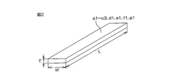
- FIG. 2 is a schematic perspective view for explaining the shape of the sample of the stretchable conductive layer.
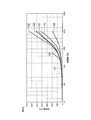
- FIG. 3A is a graph mainly showing changes in resistance values of the samples a1, b1, and c1 when 20% tensile strain is repeatedly applied 100 times at a frequency of 1.0 Hz to the samples a1, b1, and c1. is there.
- FIG. 3B is an enlarged graph showing a portion in the range of resistance values 0 ⁇ to 50 ⁇ at the broken lines A1, B1, and C1 of FIG. 3A.
- FIG. 3C mainly shows changes in resistance values of samples d1, e1, f1, and g1 when 20% tensile strain is repeatedly applied 100 times at a frequency of 1.0 Hz to samples d1, e1, f1, and g1. It is a graph which shows.
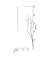
- FIG. 4 is a graph mainly showing changes in resistance values of the samples a2, b2, and c2 when 40% tensile strain is repeatedly applied 100 times at a frequency of 1.0 Hz to the samples a2, b2, and c2. is there.
- FIG. 4 is a graph mainly showing changes in resistance values of the samples a2, b2, and c2 when 40% tensile strain is repeatedly applied 100 times at a frequency of 1.0 Hz to the samples a2, b2, and c2. is there.
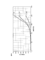
- FIG. 5A shows the elongation rates of samples a3, b3, c3, d3, e3, f3 and g3 when samples a3, b3, c3, d3, e3, f3 and g3 are stretched at a plurality of different elongation rates. It is a graph which shows resistance value.
- FIG. 5B is a graph obtained by extracting graphs for only the samples b3, d3, and e3 from the graph illustrated in FIG. 5A.
- FIG. 5C is a graph obtained by extracting graphs for only the samples d3, e3, f3, and g3 from the graph shown in FIG. 5A.
- 6A to 6C are process diagrams showing a method of manufacturing a stretchable conductive film.
- FIG. 7A to 7C are process diagrams showing another manufacturing method of the stretchable conductive film.
- 8A to 8D are schematic cross-sectional views for explaining a method of using the stretchable conductive film.
- FIG. 9 is a schematic view showing an example in which a stretchable conductive film is used as an electrode / wiring material for electrocardiogram measurement.
- FIG. 10 is a schematic view showing an example in which a stretchable conductive film is used as an electrode / wiring material for measuring myoelectricity.
- FIG. 11A is a plan view schematically showing the configuration of the test sample
- FIG. 11B is a front view schematically showing the configuration of the test sample.
- FIG. 12 is a graph showing the results of an evaluation test for a test sample.
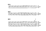
- FIG. 13A to 13E are cross-sectional views showing the configurations of stretchable conductive films according to the second to sixth embodiments, respectively.
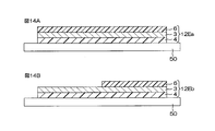
- FIG. 14A is a cross-sectional view showing a use state of the stretchable conductive film according to the sixth embodiment
- FIG. 14B is a cross-sectional view showing another example of use state of the stretchable conductive film according to the sixth embodiment. is there.
- FIG. 1 is a schematic cross-sectional view showing a configuration of a stretchable conductive film for textiles according to a first embodiment of the present invention.
- a stretchable conductive film for textiles (hereinafter simply referred to as “stretchable conductive film 1”) is a stretchable film formed on one surface of a first release film (transfer film) 2 and a first release film 2.
- the conductive layer 3 the hot melt adhesive layer 4 formed on the surface of the stretchable conductive layer 3 opposite to the first release film 2 side, and the stretchable conductive layer 3 side of the hot melt adhesive layer 4 And a second release film (protective film) 5 formed on the opposite surface.
- the stretchable conductive film 1 has a sheet shape.
- the stretchable conductive film 1 may be long and long in one direction.
- first release film 2 a release paper (release paper), a fluorine film, a polyethylene naphthalate (PEN) film in which a release agent of silicone type or non-silicone type (melamine type, acrylic type, etc.) is applied on one or both sides Polyethylene terephthalate (PET) film or the like is used.
- second release film 5 the same one as the first release film 2 is used.
- thermoplastic resins such as polyester, polyurethane, polyamide, olefin, and ethylene vinyl acetate.
- the agent preferably has a melting point of 130 ° C. or lower, a durometer hardness of 95 A or lower, and a breaking elongation of 300% or higher, a melting point of 120 ° C. or lower, a durometer hardness of 85 A or lower, and a breaking elongation of 500% or higher.
- a polyurethane-based thermoplastic resin such as a product name “SHM101-PUR” manufactured by Seadam Co., Ltd. can be used.
- the stretchable conductive layer 3 is composed of a conductive composition containing an elastomer and a conductive filler filled in the elastomer.
- the elastomer is a resin having elasticity such as, for example, a styrene elastomer, an olefin elastomer, a polyester elastomer, a polyurethane elastomer, a polyamide elastomer, or a silicone elastomer.
- Polyurethane elastomer is composed of hard segment and soft segment. Soft segment includes carbonate, ester, ether, etc. Physical properties are 100% modulus 2-20MPa, breaking strength 40-90MPa, breaking elongation It is preferable that the permanent strain is 300% to 500%, the permanent strain is 20% or less, and the thermal softening point is 150 ° C.
- the 100% modulus is 3 to 10 MPa
- the breaking strength is 50 to 75 MPa
- the breaking elongation is 350 to 450%
- permanent More preferably, the strain is 10% or less and the thermal softening point is 170 ° C. or more.
- NE-8880, MAU-9022, NE-310, NE-302HV, CU-8448, etc. manufactured by Dainichi Seika Kogyo Co., Ltd. can be used.
- DIC Corporation Pandex 372E can be used as a polyurethane-type elastomer.
- the elastomer may be composed of a single resin or may include a plurality of types of resins. Elastomers are plasticizers, processing aids, crosslinking agents, vulcanization accelerators, vulcanization aids, anti-aging agents, softening agents, and colorants from the viewpoint of improving manufacturability (workability) and flexibility. Etc. may be contained.
- the shape of the conductive filler may be a dentlite shape, a coil shape, a lump shape, a spherical shape, a flake shape, a needle shape, a fiber shape, or the like.
- the dendritic shape refers to a shape in which a rod-shaped branch branch extends in a two-dimensional direction or a three-dimensional direction from a rod-shaped main branch.
- the dendritic shape includes a shape in which the branch branch is bent in the middle and a shape in which a rod-shaped branch branch extends from the middle of the branch branch.
- the dentite-like conductive filler will be described in detail.
- the dendritic conductive filler may be, for example, a dendritic copper powder or a silver powder, and a silver-coated copper powder or a dendritic copper powder in which a silver is coated on a dendritic copper powder. It may be gold coated copper powder.
- the conductive filler is made of dendritic silver-coated copper powder, the conductive filler has a resistance value close to that of the conductive filler made of silver, and has excellent conductivity and migration resistance, although it is relatively inexpensive. Can be realized. Further, when the conductive filler is made of dendritic copper powder, a conductive filler having a low resistance value can be realized while being inexpensive.
- the conductive filler is made of dendritic silver-coated copper powder
- the polyurethane elastomer has a volume resistivity of 10E + 11 to 13 ⁇ cm, about two digits lower than other elastomers, and has a high affinity for the conductive filler containing silver. The object can be stretched well.
- the particle size of the conductive filler is 1 ⁇ m at the lower limit, preferably 2 ⁇ m.
- the lower limit is 1 ⁇ m or more, the conductive fillers are easily brought into contact with each other, and the conductivity of the conductive composition is improved.
- the upper limit of the particle size of the conductive filler is 20 ⁇ m, preferably 10 ⁇ m. When the upper limit is 20 ⁇ m or less, the thickness of the conductive layer made of the conductive composition can be reduced.
- the conductive filler is a coil shape (including a spiral shape and a spiral shape)
- the conductive filler is stretched as when the coil is pulled. Therefore, even when the elastomer is stretched, an increase in the resistance value of the conductive composition can be suppressed.
- the electroconductive composition which has elasticity and can suppress the increase in the resistance value at the time of expansion
- Table 1 shows Examples 1 to 7 of the stretchable conductive layer 3.
- Example 1 of stretchable conductive layer Dendritic silver-coated copper powder (Mitsui Metal Mining Co., Ltd.) with an average particle size of 5 ⁇ m is added to the polyurethane elastomer (DIC Corporation Pandex 372E), and the silver-coated copper powder filling rate (conductivity in the conductive composition) The filler was added so that the filling ratio of the filler was 80% by mass. Next, 40 parts by mass of a mixed solvent of isopropyl alcohol and toluene (weight ratio of isopropyl alcohol and toluene was 5: 5) was added to 100 parts by mass of the polyurethane elastomer, and the mixture was stirred with a planetary stirrer. As a result, a solution containing a polyurethane elastomer, silver-coated copper powder, and an organic solvent (hereinafter referred to as “conductive solution”) was obtained.
- conductive solution a solution containing a polyurethane elastomer
- the conductive solution was applied to one surface of the release film so that the film thickness after drying was 80 ⁇ m, and dried by heating.
- heat drying with hot air at 60 ° C., heat drying with hot air at 100 ° C., and heat drying with hot air at 120 ° C. were performed for 2 minutes each.
- a thin-film conductive composition hereinafter referred to as “conductive layer” was formed on one surface of the release film.
- samples b1, b2, and b3 of the stretchable conductive layer 3 were obtained by peeling the release film from the conductive layer.
- Example 2 of stretchable conductive layer The point that the dendritic silver coated copper powder is blended with the polyurethane elastomer so that the filling rate of the silver coated copper powder is 90% by mass, and the point that the mixed solvent is 164 parts by mass with respect to 100 parts by mass of the polyurethane elastomer. Except for the stretchable conductive layer, a conductive layer is formed on one surface of the release film in the same manner as in Example 1, the conductive layer is cut into a predetermined size, and then the release film is released from the conductive layer.
- Example 3 of stretchable conductive layer Peeling in the same manner as in Example 1 except that the dendritic silver-coated copper powder is blended with the polyurethane elastomer so that the filling rate of the silver-coated copper powder is 60% by mass and no mixed solvent is used. A conductive layer was formed on one surface of the film, the conductive layer was cut to a predetermined size, and then the release film was peeled off from the conductive layer to obtain samples a1, a2, and a3 of the stretchable conductive layer 3.
- Example 4 of stretchable conductive layer Polyurethane elastomer (NE-310, manufactured by Dainichi Seika Kogyo Co., Ltd.) is coated with dendritic silver coated copper powder (Mitsui Metal Mining Co., Ltd.) with an average particle size of 5 ⁇ m, and the filling rate of the silver coated copper powder (conductive composition) The filling ratio of the conductive filler in the product was 80% by mass. Next, 40 parts by mass of a mixed solvent of isopropyl alcohol and toluene (weight ratio of isopropyl alcohol and toluene was 5: 5) was added to 100 parts by mass of the polyurethane elastomer, and the mixture was stirred with a planetary stirrer. As a result, a solution containing a polyurethane elastomer, silver-coated copper powder, and an organic solvent (hereinafter referred to as “conductive solution”) was obtained.
- conductive solution a solution containing a polyurethane e
- the conductive solution was applied to one surface of the release film so that the film thickness after drying was 60 ⁇ m, and dried by heating.
- heat drying with hot air at 60 ° C., heat drying with hot air at 100 ° C., and heat drying with hot air at 120 ° C. were performed for 2 minutes each.
- a thin-film conductive composition hereinafter referred to as “conductive layer” was formed on one surface of the release film.
- Example 5 of stretchable conductive layer A conductive layer is formed on one surface of the release film in the same manner as in Example 4 except that the conductive solution is applied to one surface of the release film so that the film thickness after drying is 40 ⁇ m. After cutting into a predetermined size, the release film was peeled off from the conductive layer to obtain samples e1 and e3 of the stretchable conductive layer 3.
- Example 6 of stretchable conductive layer A polyurethane elastomer (NE-310, manufactured by Dainichi Seika Kogyo Co., Ltd.) is coated with a dendritic silver powder (Mitsui Metal Mining Co., Ltd.) with an average particle size of 5 ⁇ m, and the filling rate of the silver powder (the conductive filler in the conductive composition The filling ratio was 80% by mass. Next, 40 parts by mass of a mixed solvent of isopropyl alcohol and toluene (weight ratio of isopropyl alcohol and toluene was 5: 5) was added to 100 parts by mass of the polyurethane elastomer, and the mixture was stirred with a planetary stirrer. As a result, a solution containing a polyurethane-based elastomer, silver powder, and an organic solvent (hereinafter referred to as “conductive solution”) was obtained.
- conductive solution a solution containing a polyurethane-based elastomer
- samples f1 and f3 of the stretchable conductive layer 3 were obtained by cutting the conductive layer into a predetermined size and then peeling the release film from the conductive layer.
- Example 7 of stretchable conductive layer A conductive layer is formed on one surface of the release film in the same manner as in Example 6 except that the conductive solution is applied to one surface of the release film so that the film thickness after drying is 40 ⁇ m. After cutting into a predetermined size, samples g1 and g3 of the stretchable conductive layer 3 were obtained by peeling the release film from the conductive layer.
- Table 1 shows the filling rate of the conductive filler in each sample obtained above, and the length L, width W, and thickness T of each sample. Moreover, the schematic diagram of the shape of each sample was shown in FIG. As shown in FIG. 2, each sample has a rectangular band shape in plan view. In FIG. 2, L indicates the length of the sample, W indicates the width of the sample, and T indicates the thickness of the sample.
- First evaluation experiment A first evaluation experiment was performed on samples a1, b1, c1, d1, e1, f1, and g1. In the first evaluation experiment, first, the sample was attached to a self-made fatigue tester. Here, the self-made fatigue testing machine is provided with a pair of 30 cm square acrylic plates that operate so as to reciprocate in opposite directions.
- the resistance values of the samples a1, b1, c1, d1, e1, f1, and g1 are the number of times the tensile strain is applied. The larger the number, the larger.
- the resistance value of each sample a1, b1, c1, d1, e1, f1, g1 decreases rapidly. After that, those resistance values gradually decreased (see the third period P3).
- the increase rate of the resistance value of each sample a1, b1, c1, d1, e1, f1, g1 is different.
- the resistance value at the start of the second period P2 is 0.8 ⁇
- the maximum resistance value in the second period P2 is 178.6 ⁇ .
- the resistance value at the start of the second period P2 was 1.2 ⁇
- the maximum resistance value just before the end of the second period P2 was 17.8 ⁇
- the resistance value at the start of the second period P2 was 2.0 ⁇
- the maximum resistance value in the second period P2 was 22.9 ⁇ .
- the filling rate of the dendritic conductive filler is 75% by mass or more and 90% by mass or less in the conductive composition, the resistance value when 20% tensile strain is repeatedly applied 100 times at a frequency of 1.0 Hz. Can be expected to be smaller.
- the resistance value at the start of the second period P2 was 1.4 ⁇ , and the maximum resistance value in the second period P2 was 18.0 ⁇ .
- the resistance value at the start of the second period P2 was 5.8 ⁇ , and the maximum resistance value in the second period P2 was 40.6 ⁇ .
- the resistance value at the start of the second period P2 was 0.8 ⁇ , and the maximum resistance value in the second period P2 was 8.4 ⁇ .
- the resistance value at the start of the second period P2 was 1.8 ⁇ , and the maximum resistance value in the second period P2 was 18.2 ⁇ .
- the samples f1 and g1 using silver powder have an increased resistance value in the second period P2 compared to the samples d1 and e1 using silver-coated copper powder. It can be seen that both the rate and the maximum resistance value in the second period P2 are small. In other words, assuming that the length and width of the samples are the same, in order to keep the maximum resistance value in the second period P2 below a predetermined value, in the samples f1 and g1 using silver powder, The thickness of the stretchable conductive layer can be reduced as compared with the samples d1 and e1 using powder. [Second Evaluation Experiment] A second evaluation experiment was performed on samples a2, b2, and c2.
- the sample is maintained in a natural state for 10 seconds. This period may be referred to as a first period P1. Thereafter, 40% tensile strain is repeatedly applied to the sample 100 times at a frequency of 1.0 Hz. This period may be referred to as a second period P2. The second period T2 is 100 seconds. Finally, the sample is kept in the natural state again for 120 seconds. This period may be referred to as a third period P3. And the resistance between the both ends of a sample was measured in each of these periods.
- FIG. 4 is a graph showing the results of the second evaluation experiment.
- broken lines A2, B2, and C2 indicate changes in resistance values of samples a2, b2, and c2, respectively.
- P1, P2, and P3 represent a first period P1, a second period P2, and a third period P3, respectively.
- the resistance values of the samples a2, b2, and c2 increased as the number of times of applying the tensile strain increased.
- the resistance values of the samples a2, b2, and c2 rapidly decreased, and thereafter, the resistance values gradually decreased (see the third period P3).
- the increase rate of the resistance value of each sample a2, b2, c2 is different.
- the resistance value at the start of the second period P2 was 0.3 ⁇
- the maximum resistance value in the second period P2 was 200 ⁇ or more (measurement limit).
- the resistance value at the start of the second period P2 was 0.3 ⁇
- the maximum resistance value in the second period P2 was 31.4 ⁇ .
- the resistance value at the start of the second period P2 was 1.4 ⁇
- the maximum resistance value in the second period P2 was 41.9 ⁇ .
- the maximum resistance value of sample a2 is 50 ⁇ or more. In c2, the maximum resistance value is 50 ⁇ or less. Therefore, if the filling rate of the dendritic conductive filler is 70% by weight or more and 95% by weight or less in the conductive composition, the resistance value when 40% tensile strain is repeatedly applied 100 times at a frequency of 1.0 Hz. Can be expected to decrease.
- the resistance value when 40% tensile strain is repeatedly applied 100 times at a frequency of 1.0 Hz. can be expected to be smaller.
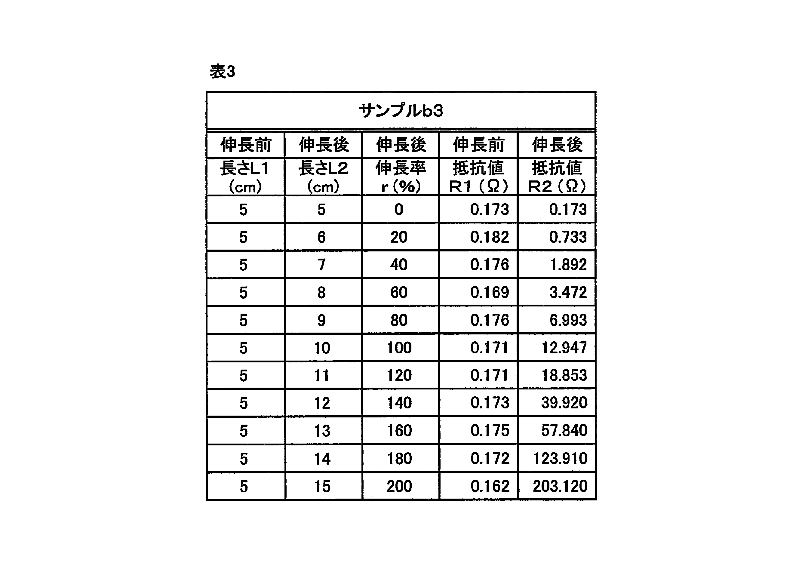
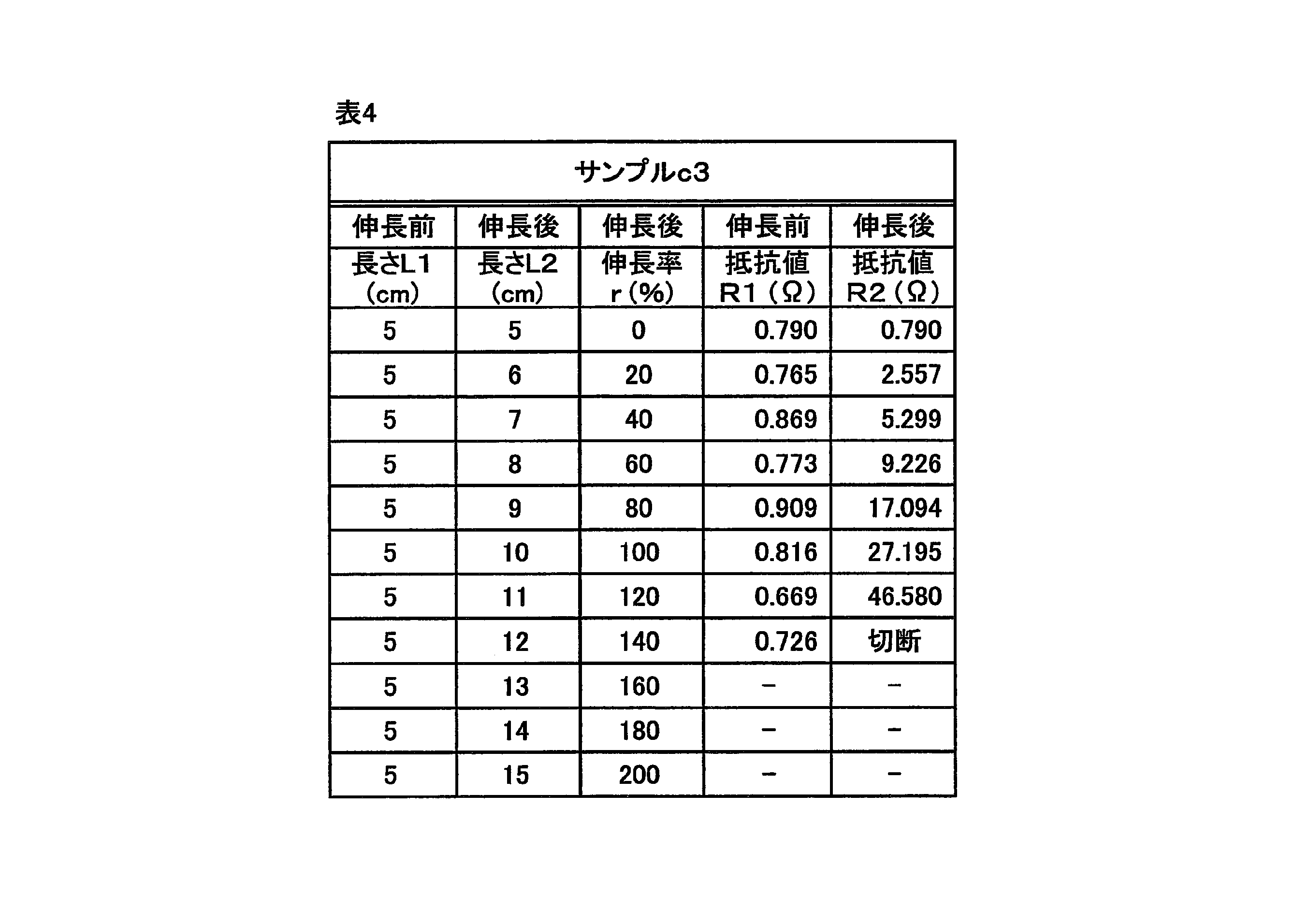
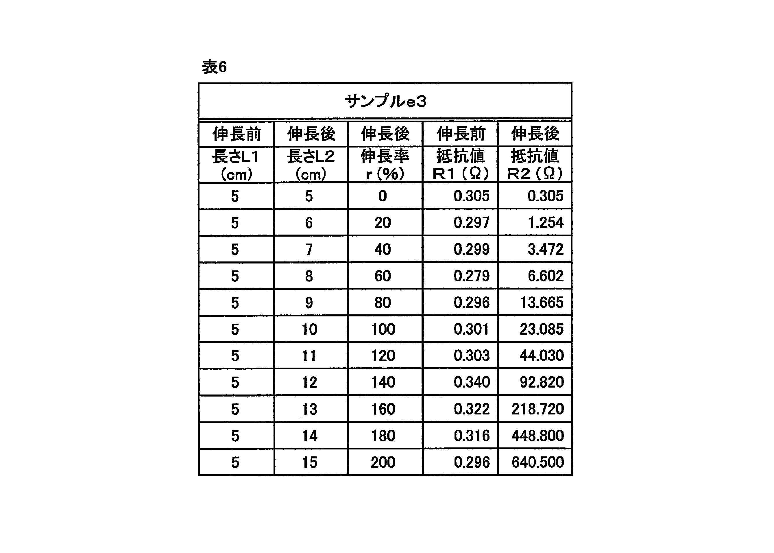
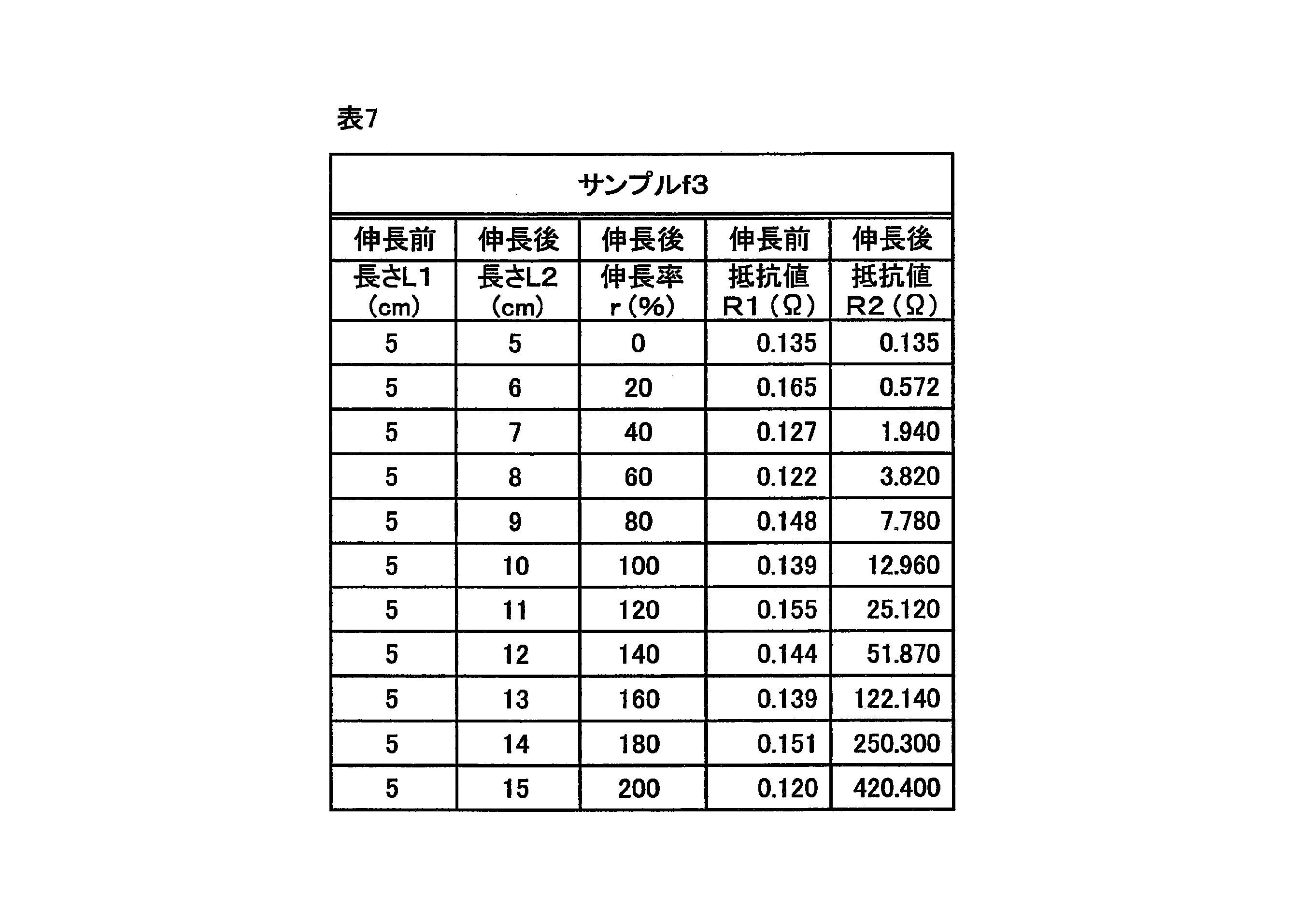
- a third evaluation experiment was performed on samples a3, b3, c3, d3, e3, f3, and g3. The third evaluation experiment is performed as follows. First, the resistance value between both ends of the sample before stretching is measured. Thereafter, the sample is stretched to a plurality of predetermined lengths, and a resistance value between both ends of the stretched sample is measured. Such a resistance value measurement was performed on a plurality of types of elongation rates that differed by 20% in a range from 0% to 200%.
- Table 2 shows the results of the third evaluation experiment for sample a3.
- Table 3 shows the results of the third evaluation experiment for sample b3.
- Table 4 shows the results of the third evaluation experiment for sample c3.
- Table 5 shows the result of the third evaluation experiment for the sample d3.
- Table 6 shows the result of the third evaluation experiment for the sample e3.
- Table 7 shows the result of the third evaluation experiment for the sample f3.
- Table 8 shows the result of the third evaluation experiment for sample g3.
- FIG. 5A, 5B and 5C are graphs showing the results of the third evaluation experiment.
- broken lines A3, B3, C3, D3, E3, F3, and G3 indicate resistance values with respect to the elongation rates of samples a3, b3, c3, d3, e3, f3, and g3, respectively.
- FIG. 5B is a graph showing only B3, D3 and E3 among the broken lines A3 to G3 in FIG. 5A.
- FIG. 5C is a graph showing only D3, E3, F3 and G3 among the broken lines A3 to G3 in FIG. 5A.
- the length L1 represents the length of the sample before extension.
- Each sample a3, b3, c3, d3, e3, f3 and g3 has a length L1 before extension of 5 cm.
- the length L2 represents the length of the sample after extension.
- the expansion ratio r is a value calculated based on the formula (1).
- the resistance value R1 represents the resistance value before elongation of the sample.
- the resistance value R2 represents the resistance value after elongation of the sample.
- the resistance value R2 at the time of expansion with an expansion ratio of 120% is 50 ⁇ or less.
- Examples 1 to 7 are conductive compositions that can be stretched and can suppress an increase in resistivity during stretching.
- the sample c3 was cut when it was stretched at a stretch rate of 140%, and became non-conductive (see also Table 4).
- the sample a3 was not cut when it was stretched at a stretch rate of 160%, but became non-conductive (see also Table 2).
- samples b3, d3, e3, f3, and g3 did not become non-conductive even when the expansion rate was 200%, as shown in FIGS. 5A, 5B, and 5C.
- the resistance values R2 of the samples b3, d3, e3, f3 and g3 when stretched at a stretch rate of 200% were 203 ⁇ , 481 ⁇ , 641 ⁇ , 420 ⁇ , and 520 ⁇ , respectively (see also Tables 3 to 8).
- the filling rate of the conductive filler in the conductive composition is 70% by mass or more and 95% by mass or less, the stretchability is high and the increase in the resistance value at the time of extension can be suppressed. Moreover, if the filling rate of the conductive filler in the conductive composition is 75% by mass or more and 90% by mass or less, it can be predicted that the stretchability is higher and the increase in the resistance value at the time of elongation can be further suppressed.
- the filling rate of the conductive filler in the conductive composition is 75% by mass or more and 85% by mass or less, it can be predicted that the stretchability is extremely high and the increase in resistance value at the time of elongation can be more effectively suppressed. .
- the first laminated film 21 is formed by forming the stretchable conductive layer 3 on one surface of the first release film 2.
- the second laminated film 22 is formed by forming the hot melt adhesive layer 4 on one surface of the second release film 5.
- the stretchable conductive layer 3 side surface of the first laminated film 21 and the hot melt adhesive layer 4 side surface of the second laminated film 22 are laminated and bonded. Thereby, the stretchable conductive film 1 is obtained.
- FIG. 7A to 7C are process diagrams showing another manufacturing method of the stretchable conductive film 1.
- FIG. 7A to 7C are process diagrams showing another manufacturing method of the stretchable conductive film 1.
- a hot melt adhesive layer 4 is formed on the surface of the stretchable conductive layer 3 opposite to the first release film 2 side.
- the 2nd peeling film 5 is affixed on the surface on the opposite side to the stretchable conductive layer 3 side in the hot-melt-adhesive agent layer 4.
- FIG. 7C the stretchable conductive film 1 is obtained.
- a method of using the stretchable conductive film 1 will be described with reference to FIGS. 8A to 8D.
- the stretchable conductive film 1 is cut into a shape according to the purpose of use.
- the second release film 5 is peeled from the stretchable conductive film 1.
- the stretchable conductive film 1 from which the second release film 5 has been peeled (hereinafter sometimes referred to as “stretchable conductive film 11”) is used as the hot melt adhesive layer. It is placed on the textile fabric 50 so that the four-side surface faces the textile fabric 50. Then, the stretchable conductive film 11 is thermocompression bonded to the textile fabric 50 using an iron or the like.
- the stretchable conductive film 1 (hereinafter sometimes referred to as “stretchable conductive film 12”) composed of the stretchable conductive layer 3 and the hot-melt adhesive layer 4 may be used. It will be in the state affixed on textile fabric 50.
- stretchable conductive film for textiles The stretchable conductive film 1 is used as an electrode / wiring material for biological information measurement such as electrocardiogram measurement and myoelectric measurement.
- FIG. 9 is a schematic diagram showing an example in which the stretchable conductive film 1 is used as an electrode / wiring material for electrocardiogram measurement.
- a wiring pattern for electrocardiogram measurement composed of a stretchable conductive film 12 is affixed to the front and back surface of a shirt 60 made of stretchable fabric.
- the electrocardiographic wiring pattern includes a first wiring 61, a second wiring 62, and a third wiring 63.
- Each wiring 61, 62, 63 is composed of electrode portions 61a, 62a, 63a, terminal portions 61b, 62b, 63b, and wiring portions 61c, 62c, 63c connecting them.
- the electrode portions 61a, 62a, and 63a are portions that come into contact with the human body, and constitute an electrocardiographic measurement electrode.
- the electrode portions 61 a and 62 a of the first wiring 61 and the second wiring 62 are arranged at positions corresponding to the chest on the front back surface of the shirt 60.
- the electrode part 63 a of the third wiring 63 is disposed at a position corresponding to the side part of the front back surface of the shirt 60.
- the terminal portions 61b, 62b, and 63b constitute terminals for connecting the wirings 61, 62, and 63 to the electrocardiograph.
- the terminal portions 61 b, 62 b, 63 b are arranged at the lower end portion of the front side back surface of the shirt 60.
- a long stretchable protective film 64 that covers the wiring portions 61c, 62c, and 63c of the wirings 61, 62, and 63 is attached to the front back surface of the shirt 60.
- the stretchable protective film 64 insulates the surfaces (stretchable conductive layer 3) of the wiring portions 61c, 62c, and 63c, or scratches (scratches) on the surfaces of the wiring portions 61c, 62c, and 63c (stretchable conductive layer 3). It has a role to prevent the occurrence.
- As the stretchable protective film 64 for example, an elastomer used in the stretchable conductive layer 3 filled with carbon black can be used.
- FIG. 10 is a schematic diagram showing an example in which the stretchable conductive film 1 is used as an electrode / wiring material for myoelectric measurement.
- a wiring pattern for measuring myoelectricity composed of the stretchable conductive film 12 is affixed to the back surface (inner peripheral surface) of the arm cover 70 attached to the forearm.
- the arm cover 70 is made of a stretchable fabric.
- the myoelectric measurement wiring pattern includes a first wiring 71, a second wiring 72, and a third wiring 73.
- Each wiring 71, 72, 73 consists of electrode parts 71a, 72a, 73a, terminal parts 71b, 72b, 73b, and wiring parts 71c, 72c, 73c connecting them.
- the electrode portions 71a, 72a, 73a are portions that come into contact with the human body and constitute myoelectric measurement electrodes.
- the electrode portions 71 a, 72 a, 73 a are disposed at positions corresponding to the forearm muscle portions on the back surface of the arm cover 70.
- the terminal portions 71b, 72b, and 73b constitute terminals for connecting the wirings 71, 72, and 73 to the myoelectric measuring instrument.
- the terminal portions 71b, 72b, 73b are arranged at one end portion of the arm cover 70.
- a long stretchable protective film 74 that covers the wiring portions 71c, 72c, and 73c of the wires 71, 72, and 73 is attached to the back surface of the arm cover 70.
- the stretchable protective film 74 is made of the same material as the stretchable protective film 64 described above.
- [Evaluation test of stretchable conductive film] A plurality of types of samples of the stretchable conductive film 1 are prepared, and these samples are attached to the stretchable fiber fabric by the method described with reference to FIGS. 8A to 8D, so that a plurality of types of test samples h, i, j was created. Note that the stretchable conductive film 1 was attached to the stretchable fiber fabric by thermocompression bonding at 120 ° C. using an iron. Then, an evaluation test was performed on each test sample h, i, j. Details of the evaluation test and evaluation results will be described later.
- FIG. 11A is a plan view schematically showing the configuration of a test sample.
- FIG. 11B is a front view schematically showing the configuration of the test sample.
- Each test sample h, i, j has a rectangular stretchable fiber fabric 80 in a plan view and a stretchable conductive film 12 in a rectangular shape in a plan view attached to the center of the surface of the stretchable fiber fabric 80.
- the stretchable conductive film 12 attached to the stretchable fiber fabric 80 includes a hot melt adhesive layer 4 on the stretchable fiber fabric 80 side, and a stretchable conductive layer 3 formed on the hotmelt adhesive layer 4. Consists of.
- the shape, size, material, etc. of the stretchable fiber fabric 80 are the same.
- the thickness of the stretchable fiber fabric 80 is 0.37 mm.
- the planar shape and size of the stretchable conductive film 12 are the same in each test sample h, i, j.
- the distance D1 between each long side of the stretchable fiber fabric 80 and the long side of the stretchable conductive film 12 corresponding to the long side is 10 mm.
- a distance D2 between each short side of the stretchable fiber fabric 80 and the short side of the stretchable conductive film 12 corresponding to the short side is 25 mm.
- the material and thickness of the conductive composition of the stretchable conductive layer 3 are the same.
- the conductive filler is a dendritic silver-coated copper powder (manufactured by Mitsui Mining & Smelting Co., Ltd.) having an average particle diameter of 5 ⁇ m.
- the filling rate of silver-coated copper powder (filling rate of conductive filler in the conductive composition) is 80% by mass.
- the elastomer is a polyurethane elastomer (NE-310 manufactured by Dainichi Seika Kogyo Co., Ltd.).
- the thickness of the stretchable conductive layer 3 is 60 ⁇ m.
- the material of the hot melt adhesive layer 4 is the same, but the thickness is different.
- the hot melt adhesive layer 4 is a thermoplastic polyurethane (SHM101-PUR, manufactured by Seadam Co., Ltd., melting point: 115 ° C., durometer hardness: 75 A, elongation at break: 800%).
- the thickness of the test sample h is 30 ⁇ m
- the thickness of the test sample i is 70 ⁇ m
- the thickness of the test sample j is 100 ⁇ m.
- 3 samples for each test h, i, j were prepared. And the evaluation test was done with respect to each sample for a test. In the evaluation test, one end of the test sample is fixed, and the other is pulled at a constant speed (in this example, 200 mm / sec), and the stretch rate [%] of the test sample and the stretchable conductive film 12 are set at regular intervals. The resistance value [ ⁇ ] between both ends was measured. The median value of the resistance values of the three test samples h for each time was taken as the resistance value of the test sample h for each time. Further, the median value of the resistance values of the three test samples i for each time was defined as the resistance value of the test sample i for each time. In addition, the median value of the resistance values of the three test samples j for each time was defined as the resistance value of the test sample j for each time.
- FIG. 12 is a graph showing the results of an evaluation test on a test sample. Curves H, I, and J in FIG. 12 show changes in resistance values of the test samples h, i, and j, respectively.
- the stretchable conductive film 1 is composed of the first release film 2, the stretchable conductive layer 3, the hot melt adhesive layer 4, and the second release film 5.
- the stretchable conductive film includes a stretchable conductive layer and a hot melt adhesive layer formed on one surface of the stretchable conductive layer, the stretchable conductive film has a structure different from that of the above-described embodiment. Also good.
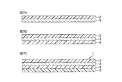
- FIG. 13A is a cross-sectional view showing a configuration of a stretchable conductive film according to a second embodiment of the present invention.
- This stretchable conductive film 1A includes a stretchable conductive layer 3, a hot melt adhesive layer 4 formed on one surface of the stretchable conductive layer 3, and the stretchable conductive layer 3 side of the hot melt adhesive layer 4. Is composed of a release film 5 formed on the opposite surface.
- FIG. 13B is a cross-sectional view showing the configuration of the stretchable conductive film according to the third embodiment of the present invention.
- the stretchable conductive film 1B includes a stretchable conductive layer 3, a hot melt adhesive layer 4 formed on one surface of the stretchable conductive layer 3, and the hot melt adhesive layer 4 side of the stretchable conductive layer 3. Is composed of a release film 2 formed on the opposite surface.
- FIG. 13C is a cross-sectional view showing the configuration of the stretchable conductive film according to the fourth embodiment of the present invention.
- This stretchable conductive film 1C includes a stretchable conductive layer 3, a hot melt adhesive layer 4 formed on one surface of the stretchable conductive layer 3, and the hot melt adhesive layer 4 side of the stretchable conductive layer 3.
- the stretchable protective film 64 insulates part or all of the surface of the stretchable conductive layer 3 opposite to the hot melt adhesive layer 4 side, or the stretchable conductive film 64 and the hot melt adhesive layer 4 side of the stretchable conductive layer 3. Has the role of preventing the occurrence of scratches (scratches) on part or all of the opposite surface.
- an elastomer used in the stretchable conductive layer 3 filled with carbon black can be used, and similarly, a plasticizer, a processing aid, a crosslinking agent, a vulcanization agent, and the like. Additives such as accelerators, vulcanization aids, anti-aging agents, softeners, and colorants may be included.
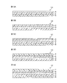
- FIG. 13D is a cross-sectional view showing the configuration of the stretchable conductive film according to the fifth embodiment of the present invention.
- This stretchable conductive film 1D includes a stretchable conductive layer 3, a hot melt adhesive layer 4 formed on one surface of the stretchable conductive layer 3, and the hot melt adhesive layer 4 side of the stretchable conductive layer 3.
- the stretchable protective layer 6 is formed on at least a part of the surface on the opposite side, and the stretchable protective layer 6 is covered on the surface side of the stretchable conductive layer 3 opposite to the hot melt adhesive layer 4 side. It is comprised from the peeling film 7 formed in this.
- FIG. 13E is a cross-sectional view showing the configuration of the stretchable conductive film according to the sixth embodiment of the present invention.
- This stretchable conductive film 1E includes a stretchable conductive layer 3, a hot melt adhesive layer 4 formed on one surface of the stretchable conductive layer 3, and the hot melt adhesive layer 4 side of the stretchable conductive layer 3.
- the stretchable protective layer 6 is formed on at least a part of the surface on the opposite side, and the stretchable protective layer 6 is covered on the surface side of the stretchable conductive layer 3 opposite to the hot melt adhesive layer 4 side.
- a second release film 8 formed on the surface of the hot melt adhesive layer 4 opposite to the stretchable conductive layer 3 side.
- FIG. 14A is a cross-sectional view showing a use state of the stretchable conductive film 1E.
- the stretchable conductive film 1E When using the stretchable conductive film 1E, first, the stretchable conductive film 1E is cut into a shape according to the purpose of use. Next, the second release film 8 is peeled from the stretchable conductive film 1E. Thereafter, the stretchable conductive film 1E from which the second release film 8 has been peeled is placed on the textile fabric 50 so that the hot-melt adhesive layer 4 side surface faces the textile fabric 50. And the stretchable conductive film 1E is thermocompression bonded to the textile fabric 50 using an iron or the like. Thereafter, the first release film 7 is peeled off from the stretchable conductive film 1E. Thereby, as shown to FIG. 14A, the stretchable conductive film 1E (it shows with 12Ea in FIG. 14A) which consists of the stretchable protective layer 6, the stretchable conductive layer 3, and the hot-melt-adhesive agent layer 4 is textile fabric. 50 is pasted.
- FIG. 14B is a cross-sectional view showing a use state of the stretchable conductive film 1E in which the stretchable protective layer 6 is formed only on a part of the surface of the stretchable conductive layer 3.
- the stretchable protective layer 6 is formed only on a part of the surface of the stretchable conductive layer 3, as shown in FIG. 14B, the stretchable conductive layer 3 and one surface of the stretchable conductive layer 3 are formed.
- Stretchable conductive film 1E comprising a stretchable protective layer 6 formed only in part and a hot melt adhesive layer 4 formed on the other surface of the stretchable conductive layer 3 (indicated by reference numeral 12Eb in FIG. 14B) However, it will be in the state affixed on the textile fabric 50.
- the exposed stretchable conductive layer can be used as an electrode or a wiring.
- the structure in which the stretchable protective layer 6 is formed only on a part of the surface of the stretchable conductive layer 3 is produced by cutting out the stretchable protective layer 6 that has been previously patterned on the stretchable conductive layer 3. be able to.
- affixing a stretchable protective film on a part of the stretchable conductive layer affixed to the textile fabric via a hot melt adhesive layer allows only a part of the surface of the stretchable conductive layer 3 to be attached.
- a configuration in which a stretchable protective film is formed can also be obtained.
Landscapes
- Health & Medical Sciences (AREA)
- Life Sciences & Earth Sciences (AREA)
- Chemical & Material Sciences (AREA)
- Organic Chemistry (AREA)
- Physics & Mathematics (AREA)
- Biomedical Technology (AREA)
- Veterinary Medicine (AREA)
- Biophysics (AREA)
- Pathology (AREA)
- Engineering & Computer Science (AREA)
- Public Health (AREA)
- Heart & Thoracic Surgery (AREA)
- Medical Informatics (AREA)
- Molecular Biology (AREA)
- Surgery (AREA)
- Animal Behavior & Ethology (AREA)
- General Health & Medical Sciences (AREA)
- Dispersion Chemistry (AREA)
- Spectroscopy & Molecular Physics (AREA)
- Cardiology (AREA)
- Laminated Bodies (AREA)
- Conductive Materials (AREA)
- Adhesive Tapes (AREA)
Abstract
Description
[ストレッチャブル導電層の実施例]
ストレッチャブル導電層3の実施例について説明する。

ポリウレタン系エラストマー(DIC株式会社製 パンデックス372E)に、平均粒径5μmでデンドライト状の銀コート銅粉(三井金属鉱業株式会社製)を、銀コート銅粉の充填率(導電性組成物における導電性フィラーの充填率)が80質量%となるように配合した。次いで、ポリウレタン系エラストマー100質量部に対して、イソプロピルアルコールとトルエンとの混合溶媒(イソプロピルアルコールとトルエンの重量比が5:5)を40質量部添加し、遊星攪拌機によって撹拌した。これにより、ポリウレタン系エラストマーと銀コート銅粉と有機溶剤とを含む溶液(以下、「導電性溶液」という。)を得た。
[ストレッチャブル導電層の実施例2]
銀コート銅粉の充填率が90質量%となるようにポリウレタン系エラストマーにデンドライト状の銀コート銅粉を配合する点およびポリウレタン系エラストマー100質量部に対して混合溶剤を164質量部とする点を除いては、実施例1と同様にして剥離フィルムの一表面に導電層を形成し、導電層を所定の大きさに切断した後、導電層から剥離フィルムを剥離することにより、ストレッチャブル導電層3のサンプルc1,c2およびc3を得た。
[ストレッチャブル導電層の実施例3]
銀コート銅粉の充填率が60質量%となるようにポリウレタン系エラストマーにデンドライト状の銀コート銅粉を配合する点および混合溶剤を使用しない点を除いては、実施例1と同様にして剥離フィルムの一表面に導電層を形成し、導電層を所定の大きさに切断した後、導電層から剥離フィルムを剥離することにより、ストレッチャブル導電層3のサンプルa1,a2およびa3を得た。
[ストレッチャブル導電層の実施例4]
ポリウレタン系エラストマー(大日精化工業株式会社製 NE-310)に、平均粒径5μmでデンドライト状の銀コート銅粉(三井金属鉱業株式会社製)を、銀コート銅粉の充填率(導電性組成物における導電性フィラーの充填率)が80質量%となるように配合した。次いで、ポリウレタン系エラストマー100質量部に対して、イソプロピルアルコールとトルエンとの混合溶媒(イソプロピルアルコールとトルエンの重量比が5:5)を40質量部添加し、遊星攪拌機によって撹拌した。これにより、ポリウレタン系エラストマーと銀コート銅粉と有機溶剤とを含む溶液(以下、「導電性溶液」という。)を得た。
[ストレッチャブル導電層の実施例5]
乾燥後の膜厚が40μmとなるように導電性溶液を剥離フィルムの一表面に塗布する点を除いては、実施例4と同様にして剥離フィルムの一表面に導電層を形成し、導電層を所定の大きさに切断した後、導電層から剥離フィルムを剥離することにより、ストレッチャブル導電層3のサンプルe1,e3を得た。
[ストレッチャブル導電層の実施例6]
ポリウレタン系エラストマー(大日精化工業株式会社製 NE-310)に、平均粒径5μmでデンドライト状の銀粉(三井金属鉱業株式会社製)を、銀粉の充填率(導電性組成物における導電性フィラーの充填率)が80質量%となるように配合した。次いで、ポリウレタン系エラストマー100質量部に対して、イソプロピルアルコールとトルエンとの混合溶媒(イソプロピルアルコールとトルエンの重量比が5:5)を40質量部添加し、遊星攪拌機によって撹拌した。これにより、ポリウレタン系エラストマーと銀粉と有機溶剤とを含む溶液(以下、「導電性溶液」という。)を得た。
[ストレッチャブル導電層の実施例7]
乾燥後の膜厚が40μmとなるように導電性溶液を剥離フィルムの一表面に塗布する点を除いては、実施例6と同様にして剥離フィルムの一表面に導電層を形成し、導電層を所定の大きさに切断した後、導電層から剥離フィルムを剥離することにより、ストレッチャブル導電層3のサンプルg1,g3を得た。
[第1の評価実験]
サンプルa1,b1,c1,d1,e1,f1,g1に対して、第1の評価実験を行った。第1の評価実験では、まず、サンプルを自作の疲労試験機に取り付けた。ここで、自作の疲労試験機は、対向する方向に往復可能なように動作する30cm四方の一対のアクリル板を設けたものである。このアクリル板の表面に、サンプルの両端をそれぞれ固着させ、さらに両端をワニ口クリップで挟持して電気抵抗測定装置と接続した。次いで、サンプルを、10秒間、自然状態で維持する。この期間を第1期間P1という場合がある。この後、サンプルに対して、20%引張歪を周波数1.0Hzで100回繰り返して加える。この期間を第2期間P2という場合がある。第2期間P2は、100秒である。最後に、サンプルを、120秒の間、再び自然状態で維持する。この期間を第3期間P3という場合がある。そして、これらの各期間中において、サンプルの両端間の抵抗を測定した。
各サンプルa1,b1,c1,d1,e1,f1,g1の伸張前の長さL1は、15cmであるので、20%引張歪が加えられたときの各サンプルa1,b1,c1,d1,e1,f1,g1の伸張後の長さは18cmとなる。
[第2の評価実験]
サンプルa2,b2,c2に対して、第2の評価実験を行った。第2の評価実験では、まず、サンプルを、10秒間、自然状態で維持する。この期間を第1期間P1という場合がある。この後、サンプルに対して、40%引張歪を周波数1.0Hzで100回繰り返して加える。この期間を第2期間P2という場合がある。第2期間T2は、100秒である。最後に、サンプルを、120秒の間、再び自然状態で維持する。この期間を第3期間P3という場合がある。そして、これらの各期間中において、サンプルの両端間の抵抗を測定した。
[第3の評価実験]
サンプルa3,b3,c3,d3,e3,f3,g3に対して、第3の評価実験を行った。第3の評価実験は、次のように行われる。まず、伸長前のサンプルの両端部間の抵抗値を測定する。この後、サンプルを予め定められた複数の所定長さまで伸長させ、伸長後のサンプルの両端部間の抵抗値を測定する。このような抵抗値の測定を、伸長率0%から200%までの範囲で、伸長率が20%ずつ異なる複数種類の伸長率に対して行った。


[テキスタイル用ストレッチャブル導電性フィルムの製造方法]
図6A~図6Cは、ストレッチャブル導電性フィルム1の製造方法を示す工程図である。
[テキスタイル用ストレッチャブル導電性フィルムの使用方法]
図8A~図8Dを参照して、ストレッチャブル導電性フィルム1の使用方法について説明する。
[テキスタイル用ストレッチャブル導電性フィルムの使用形態]
ストレッチャブル導電性フィルム1は、心電計測、筋電計測等の生体情報計測用の電極・配線材として使用される。
[ストレッチャブル導電性フィルムの評価試験]
ストレッチャブル導電性フィルム1のサンプルを複数種類作成し、それらのサンプルを図8A~図8Dで説明したような方法で伸縮性繊維生地に貼り付けることにより、複数種類の試験用サンプルh,i,jを作成した。なお、ストレッチャブル導電性フィルム1の伸縮性繊維生地への貼り付けは、アイロンを用いて120℃で熱圧着することにより行った。そして、各試験用サンプルh,i,jに対して、評価試験を行った。評価試験の内容および評価結果について後述する。
2,5,7,8 剥離フィルム
3 ストレッチャブル導電層
4 ホットメルト接着剤層
6 ストレッチャブル保護層
Claims (10)
- 伸縮性を有するストレッチャブル導電層と、
前記ストレッチャブル導電層の一表面に形成されたホットメルト接着剤層とを含み、
前記ストレッチャブル導電層は、エラストマーと、前記エラストマー中に充填されている導電性フィラーとを含む導電性組成物から構成されている、テキスタイル用ストレッチャブル導電性フィルム。 - 前記ホットメルト接着剤層における前記ストレッチャブル導電層側とは反対側の表面に形成された剥離フィルムをさらに含む、請求項1に記載のテキスタイル用ストレッチャブル導電性フィルム。
- 前記ストレッチャブル導電層における前記ホットメルト接着剤層側とは反対側の表面に形成された第1剥離フィルムと、
前記ホットメルト接着剤層における前記ストレッチャブル導電層側とは反対側の表面に形成された第2剥離フィルムとをさらに含む、請求項1に記載のテキスタイル用ストレッチャブル導電性フィルム。 - 前記ストレッチャブル導電層における前記ホットメルト接着剤層側とは反対側の表面の少なくとも一部に形成された伸縮性を有するストレッチャブル保護層をさらに含む、請求項1に記載のテキスタイル用ストレッチャブル導電性フィルム。
- 前記ホットメルト接着剤層における前記ストレッチャブル導電層側とは反対側の表面に形成された剥離フィルムとをさらに含む、請求項4に記載のテキスタイル用ストレッチャブル導電性フィルム。
- 前記ストレッチャブル導電層における前記ホットメルト接着剤層側とは反対側の表面側に、前記ストレッチャブル保護層を覆うように形成された第1剥離フィルムと、
前記ホットメルト接着剤層における前記ストレッチャブル導電層側とは反対側の表面に形成された第2剥離フィルムとをさらに含む、請求項4に記載のテキスタイル用ストレッチャブル導電性フィルム。 - 前記導電性フィラーがデントライト状である、請求項1~6のいずれか一項に記載のテキスタイル用ストレッチャブル導電性フィルム。
- 前記導電性フィラーがデンドライト状の銀粉である、請求項7に記載の導電性組成物。
- 前記導電性フィラーが、デンドライト状の銅粉に銀がコーティングされた、銀コート銅粉である、請求項7に記載の導電性組成物。
- 前記導電性フィラーがコイル形状である、請求項1~6のいずれか一項に記載のテキスタイル用ストレッチャブル導電性フィルム。
Priority Applications (4)
| Application Number | Priority Date | Filing Date | Title |
|---|---|---|---|
| US15/779,579 US10864701B2 (en) | 2015-11-30 | 2016-10-19 | Stretchable conductive film for textiles |
| KR1020187016379A KR102255330B1 (ko) | 2015-11-30 | 2016-10-19 | 텍스타일용 스트레처블 도전성 필름 |
| CN201680069654.7A CN108291119B (zh) | 2015-11-30 | 2016-10-19 | 纺织品用可伸缩导电性膜 |
| EP16870324.7A EP3385348B1 (en) | 2015-11-30 | 2016-10-19 | Stretchable conductive film for textiles |
Applications Claiming Priority (2)
| Application Number | Priority Date | Filing Date | Title |
|---|---|---|---|
| JP2015-233710 | 2015-11-30 | ||
| JP2015233710A JP6660542B2 (ja) | 2015-11-30 | 2015-11-30 | テキスタイル用ストレッチャブル導電性フィルム |
Publications (1)
| Publication Number | Publication Date |
|---|---|
| WO2017094384A1 true WO2017094384A1 (ja) | 2017-06-08 |
Family
ID=58797036
Family Applications (1)
| Application Number | Title | Priority Date | Filing Date |
|---|---|---|---|
| PCT/JP2016/080986 Ceased WO2017094384A1 (ja) | 2015-11-30 | 2016-10-19 | テキスタイル用ストレッチャブル導電性フィルム |
Country Status (7)
| Country | Link |
|---|---|
| US (1) | US10864701B2 (ja) |
| EP (1) | EP3385348B1 (ja) |
| JP (1) | JP6660542B2 (ja) |
| KR (1) | KR102255330B1 (ja) |
| CN (1) | CN108291119B (ja) |
| TW (1) | TWI712055B (ja) |
| WO (1) | WO2017094384A1 (ja) |
Families Citing this family (8)
| Publication number | Priority date | Publication date | Assignee | Title |
|---|---|---|---|---|
| JP6757163B2 (ja) * | 2016-03-31 | 2020-09-16 | タツタ電線株式会社 | 電磁波シールドフィルム |
| JP7161738B2 (ja) * | 2018-02-08 | 2022-10-27 | ナミックス株式会社 | 導電性ペースト、硬化物、導電性パターン、衣服及びストレッチャブルペースト |
| WO2020138477A2 (ja) * | 2018-12-27 | 2020-07-02 | 東洋紡株式会社 | 伸縮性導体形成用導電ペースト、伸縮性導体層、伸縮性導体層の製造方法、伸縮性電気配線構成体および生体情報計測装置 |
| FI3960260T3 (fi) * | 2019-11-04 | 2023-08-30 | Boreal Tech & Investment S L | Puettava laite ja menetelmä siihen |
| EP3822328A1 (en) | 2019-11-12 | 2021-05-19 | Nanoleq AG | Elongated elastic seam tape with electrical conductor |
| TW202145951A (zh) * | 2020-05-20 | 2021-12-16 | 日商東洋紡股份有限公司 | 衣服型生物體資訊測量裝置及其製造方法 |
| CN114214020A (zh) * | 2021-12-27 | 2022-03-22 | 无锡帝科电子材料股份有限公司 | 可伸缩导电胶及其制备方法、用于制备可伸缩导电胶的原料组合物 |
| CN118658662B (zh) * | 2024-05-31 | 2026-04-21 | 东华大学 | 一种可拉伸导电信号线及其制备方法和应用 |
Citations (8)
| Publication number | Priority date | Publication date | Assignee | Title |
|---|---|---|---|---|
| JPH0992032A (ja) * | 1995-07-13 | 1997-04-04 | Sumitomo Bakelite Co Ltd | 導電性銅ペースト組成物 |
| JP2004176005A (ja) * | 2002-11-29 | 2004-06-24 | Kinugawa Rubber Ind Co Ltd | 導電性弾性体組成物およびその製造方法 |
| JP2009138141A (ja) * | 2007-12-07 | 2009-06-25 | Hitachi Cable Ltd | 導電性ゴムの製造方法及び導電性ゴム |
| JP2012211256A (ja) * | 2011-03-31 | 2012-11-01 | Toyo Ink Sc Holdings Co Ltd | 導電性樹脂組成物および導電性接着シ−ト |
| JP2014162124A (ja) | 2013-02-26 | 2014-09-08 | Fujikura Ltd | 伸縮性基板、その製造方法、及び伸縮性基板を備える電子部品 |
| WO2016017644A1 (ja) * | 2014-07-31 | 2016-02-04 | タツタ電線株式会社 | 導電性組成物およびそれを備えた導電性シート |
| WO2016114298A1 (ja) * | 2015-01-14 | 2016-07-21 | 東洋紡株式会社 | 伸縮性電極および配線シート、生体情報計測用インターフェス |
| JP2016141713A (ja) * | 2015-01-30 | 2016-08-08 | タツタ電線株式会社 | 導電性組成物およびそれを備えた導電性シート |
Family Cites Families (16)
| Publication number | Priority date | Publication date | Assignee | Title |
|---|---|---|---|---|
| JP2000017242A (ja) * | 1998-06-29 | 2000-01-18 | Minnesota Mining & Mfg Co <3M> | ホットメルト接着剤組成物、熱圧着性フィルムおよびホットメルト接着剤組成物を用いた接着方法 |
| US6265460B1 (en) | 1998-06-29 | 2001-07-24 | 3M Innovative Properties Company | Hot-melt adhesive composition, heat-bonding film adhesive and adhering method using hot-melt adhesive composition |
| US7033668B2 (en) * | 2001-08-23 | 2006-04-25 | Tesa Ag | Electrically conductive, preferably unbacked adhesive tape with permanent full-area pressure sensitive adhesion, composed of a film of a pressure sensitive adhesive which is preferably coated onto an antiadhesive medium and has an alkaline surface |
| US20050095406A1 (en) * | 2003-10-31 | 2005-05-05 | Gunzel Edward C. | Attachment of cables to flexible fabrics |
| MX321310B (es) * | 2006-02-08 | 2014-06-24 | Kimberly Clark Co | Metodos y composiciones para superficies tratadas con nanoparticulas de metal. |
| KR20100074083A (ko) * | 2007-11-08 | 2010-07-01 | 닛토덴코 가부시키가이샤 | 점착 시트 및 그것을 사용한 반도체 장치의 제조 방법 |
| JP4897084B2 (ja) * | 2008-07-25 | 2012-03-14 | 株式会社エヌエスケーエコーマーク | マーク用生地およびそれを用いたマーク形成方法 |
| DE102011101579B4 (de) * | 2011-05-12 | 2015-03-05 | Otto Bock Healthcare Gmbh | Verwendung eines leitfähigen Polymermaterials für medizinische und orthopädietechnische Anwendungen |
| JP2013057296A (ja) * | 2011-09-08 | 2013-03-28 | Canon Inc | 屈曲型アクチュエータ |
| WO2014080470A1 (ja) | 2012-11-21 | 2014-05-30 | 東海ゴム工業株式会社 | 柔軟導電部材およびそれを用いたトランスデューサ |
| JP5984645B2 (ja) * | 2012-11-30 | 2016-09-06 | 日本電信電話株式会社 | 感圧センサー、及び感圧センサー装置 |
| JP5660418B1 (ja) | 2013-04-19 | 2015-01-28 | Dic株式会社 | 導電性粘着シート、その製造方法及びそれを用いて得た電子端末 |
| US9761349B2 (en) | 2013-07-08 | 2017-09-12 | Toyobo Co., Ltd. | Electrically conductive paste |
| CN106232345A (zh) | 2014-04-22 | 2016-12-14 | 沙特基础工业全球技术有限公司 | 集成的柔性透明导电膜 |
| US9460824B2 (en) | 2014-04-23 | 2016-10-04 | Xerox Corporation | Stretchable conductive film based on silver nanoparticles |
| CN104538088A (zh) | 2014-12-30 | 2015-04-22 | 江南石墨烯研究院 | 一种导电弹性复合材料的构建及制备方案 |
-
2015
- 2015-11-30 JP JP2015233710A patent/JP6660542B2/ja active Active
-
2016
- 2016-10-19 US US15/779,579 patent/US10864701B2/en active Active
- 2016-10-19 EP EP16870324.7A patent/EP3385348B1/en active Active
- 2016-10-19 CN CN201680069654.7A patent/CN108291119B/zh active Active
- 2016-10-19 WO PCT/JP2016/080986 patent/WO2017094384A1/ja not_active Ceased
- 2016-10-19 KR KR1020187016379A patent/KR102255330B1/ko active Active
- 2016-10-28 TW TW105135088A patent/TWI712055B/zh active
Patent Citations (8)
| Publication number | Priority date | Publication date | Assignee | Title |
|---|---|---|---|---|
| JPH0992032A (ja) * | 1995-07-13 | 1997-04-04 | Sumitomo Bakelite Co Ltd | 導電性銅ペースト組成物 |
| JP2004176005A (ja) * | 2002-11-29 | 2004-06-24 | Kinugawa Rubber Ind Co Ltd | 導電性弾性体組成物およびその製造方法 |
| JP2009138141A (ja) * | 2007-12-07 | 2009-06-25 | Hitachi Cable Ltd | 導電性ゴムの製造方法及び導電性ゴム |
| JP2012211256A (ja) * | 2011-03-31 | 2012-11-01 | Toyo Ink Sc Holdings Co Ltd | 導電性樹脂組成物および導電性接着シ−ト |
| JP2014162124A (ja) | 2013-02-26 | 2014-09-08 | Fujikura Ltd | 伸縮性基板、その製造方法、及び伸縮性基板を備える電子部品 |
| WO2016017644A1 (ja) * | 2014-07-31 | 2016-02-04 | タツタ電線株式会社 | 導電性組成物およびそれを備えた導電性シート |
| WO2016114298A1 (ja) * | 2015-01-14 | 2016-07-21 | 東洋紡株式会社 | 伸縮性電極および配線シート、生体情報計測用インターフェス |
| JP2016141713A (ja) * | 2015-01-30 | 2016-08-08 | タツタ電線株式会社 | 導電性組成物およびそれを備えた導電性シート |
Non-Patent Citations (1)
| Title |
|---|
| See also references of EP3385348A4 |
Also Published As
| Publication number | Publication date |
|---|---|
| KR102255330B1 (ko) | 2021-05-21 |
| EP3385348B1 (en) | 2024-09-11 |
| EP3385348A4 (en) | 2019-07-10 |
| JP2017101124A (ja) | 2017-06-08 |
| CN108291119B (zh) | 2021-07-27 |
| JP6660542B2 (ja) | 2020-03-11 |
| EP3385348A1 (en) | 2018-10-10 |
| KR20180088832A (ko) | 2018-08-07 |
| TW201727673A (zh) | 2017-08-01 |
| US20200086606A1 (en) | 2020-03-19 |
| CN108291119A (zh) | 2018-07-17 |
| US10864701B2 (en) | 2020-12-15 |
| TWI712055B (zh) | 2020-12-01 |
Similar Documents
| Publication | Publication Date | Title |
|---|---|---|
| JP6660542B2 (ja) | テキスタイル用ストレッチャブル導電性フィルム | |
| CN108701505B (zh) | 伸缩性导体片、具有粘接性的伸缩性导体片、布帛上的伸缩性导体构成的配线的形成方法 | |
| JP6938152B2 (ja) | 導電膜およびそれを備えた導電性シート | |
| TWI736572B (zh) | 伸縮性導體組成物、伸縮性導體形成用糊劑、具有由伸縮性導體組成物構成之配線的衣服及其製造方法 | |
| KR102106233B1 (ko) | 웨어러블·스마트·디바이스 | |
| JP2019162460A (ja) | 伸縮性電極シートの製造方法、伸縮性複合電極シートの製造方法、生体情報計測用インターフェスの製造方法 | |
| CN108886884B (zh) | 电磁波屏蔽膜 | |
| JP2017022236A (ja) | 配線回路基板の製造方法 | |
| KR20190033567A (ko) | 신축성 전기전도성 접착 테이프 | |
| JP2017022237A (ja) | 配線回路基板 | |
| JP7215430B2 (ja) | 生体情報計測用衣服および伸縮性積層シート | |
| TW201825013A (zh) | 伸縮性導體片、伸縮性配線、設有伸縮性配線之布帛及導電性恢復方法 | |
| WO2020013323A1 (ja) | 衣服型電子機器およびその製造方法 | |
| WO2021235235A1 (ja) | 衣服型生体情報計測装置およびその製造方法 | |
| CN115551712A (zh) | 衣服衣料粘贴用导电性层叠片及其制造方法 |
Legal Events
| Date | Code | Title | Description |
|---|---|---|---|
| 121 | Ep: the epo has been informed by wipo that ep was designated in this application |
Ref document number: 16870324 Country of ref document: EP Kind code of ref document: A1 |
|
| NENP | Non-entry into the national phase |
Ref country code: DE |
|
| ENP | Entry into the national phase |
Ref document number: 20187016379 Country of ref document: KR Kind code of ref document: A |
|
| WWE | Wipo information: entry into national phase |
Ref document number: 2016870324 Country of ref document: EP |
|
| ENP | Entry into the national phase |
Ref document number: 2016870324 Country of ref document: EP Effective date: 20180702 |