WO2017094626A1 - 作業機械用周辺監視システム - Google Patents
作業機械用周辺監視システム Download PDFInfo
- Publication number
- WO2017094626A1 WO2017094626A1 PCT/JP2016/085043 JP2016085043W WO2017094626A1 WO 2017094626 A1 WO2017094626 A1 WO 2017094626A1 JP 2016085043 W JP2016085043 W JP 2016085043W WO 2017094626 A1 WO2017094626 A1 WO 2017094626A1
- Authority
- WO
- WIPO (PCT)
- Prior art keywords
- image
- identification
- unit
- person
- work machine
- Prior art date
- Legal status (The legal status is an assumption and is not a legal conclusion. Google has not performed a legal analysis and makes no representation as to the accuracy of the status listed.)
- Ceased
Links
Images


Classifications
-
- E—FIXED CONSTRUCTIONS
- E02—HYDRAULIC ENGINEERING; FOUNDATIONS; SOIL SHIFTING
- E02F—DREDGING; SOIL-SHIFTING
- E02F9/00—Component parts of dredgers or soil-shifting machines, not restricted to one of the kinds covered by groups E02F3/00 - E02F7/00
- E02F9/26—Indicating devices
-
- E—FIXED CONSTRUCTIONS
- E02—HYDRAULIC ENGINEERING; FOUNDATIONS; SOIL SHIFTING
- E02F—DREDGING; SOIL-SHIFTING
- E02F9/00—Component parts of dredgers or soil-shifting machines, not restricted to one of the kinds covered by groups E02F3/00 - E02F7/00
- E02F9/26—Indicating devices
- E02F9/261—Surveying the work-site to be treated
-
- E—FIXED CONSTRUCTIONS
- E02—HYDRAULIC ENGINEERING; FOUNDATIONS; SOIL SHIFTING
- E02F—DREDGING; SOIL-SHIFTING
- E02F9/00—Component parts of dredgers or soil-shifting machines, not restricted to one of the kinds covered by groups E02F3/00 - E02F7/00
- E02F9/26—Indicating devices
- E02F9/267—Diagnosing or detecting failure of vehicles
-
- G—PHYSICS
- G06—COMPUTING OR CALCULATING; COUNTING
- G06T—IMAGE DATA PROCESSING OR GENERATION, IN GENERAL
- G06T1/00—General purpose image data processing
-
- G—PHYSICS
- G06—COMPUTING OR CALCULATING; COUNTING
- G06T—IMAGE DATA PROCESSING OR GENERATION, IN GENERAL
- G06T1/00—General purpose image data processing
- G06T1/20—Processor architectures; Processor configuration, e.g. pipelining
-
- H—ELECTRICITY
- H04—ELECTRIC COMMUNICATION TECHNIQUE
- H04N—PICTORIAL COMMUNICATION, e.g. TELEVISION
- H04N7/00—Television systems
- H04N7/18—Closed-circuit television [CCTV] systems, i.e. systems in which the video signal is not broadcast
-
- H—ELECTRICITY
- H04—ELECTRIC COMMUNICATION TECHNIQUE
- H04N—PICTORIAL COMMUNICATION, e.g. TELEVISION
- H04N7/00—Television systems
- H04N7/18—Closed-circuit television [CCTV] systems, i.e. systems in which the video signal is not broadcast
- H04N7/181—Closed-circuit television [CCTV] systems, i.e. systems in which the video signal is not broadcast for receiving images from a plurality of remote sources
-
- G—PHYSICS
- G06—COMPUTING OR CALCULATING; COUNTING
- G06T—IMAGE DATA PROCESSING OR GENERATION, IN GENERAL
- G06T7/00—Image analysis
- G06T7/0002—Inspection of images, e.g. flaw detection
- G06T7/0004—Industrial image inspection
-
- G—PHYSICS
- G06—COMPUTING OR CALCULATING; COUNTING
- G06V—IMAGE OR VIDEO RECOGNITION OR UNDERSTANDING
- G06V20/00—Scenes; Scene-specific elements
- G06V20/50—Context or environment of the image
- G06V20/52—Surveillance or monitoring of activities, e.g. for recognising suspicious objects
Definitions
- the present invention relates to a work machine periphery monitoring system for monitoring the periphery of a work machine.
- a work machine periphery monitoring system includes a human detection unit that detects a person existing around the work machine, and a control unit that controls an output device mounted on the work machine.
- the control unit displays an output image including an image portion generated using a captured image of an imaging device attached to the work machine and an icon of the work machine on a display device, and around the icon.
- the image portion on the side corresponding to the presence direction of the person detected by the person detection unit is emphasized.
- the above-described means provides a work machine periphery monitoring system that allows an operator to easily recognize in which region in the display image a person detected by the work machine exists.
- FIG. 1 is a side view of an excavator as a construction machine on which a periphery monitoring system 100 according to an embodiment of the present invention is mounted.
- An upper swing body 3 is mounted on the lower traveling body 1 of the excavator so as to be swingable via a swing mechanism 2.
- a boom 4 is attached to the upper swing body 3.
- An arm 5 is attached to the tip of the boom 4, and a bucket 6 is attached to the tip of the arm 5.
- the boom 4, the arm 5, and the bucket 6 constitute an excavation attachment, and are hydraulically driven by the boom cylinder 7, the arm cylinder 8, and the bucket cylinder 9, respectively.
- the upper swing body 3 is provided with a cabin 10 and is mounted with a power source such as an engine.
- An imaging device 40 is attached to the upper part of the upper swing body 3.
- the rear camera 40B, the left side camera 40L, and the right side camera 40R are attached to the rear end upper part, the left end upper part, and the right end upper part of the upper swing body 3.
- a controller 30 and an output device 50 are installed in the cabin 10.
- FIG. 2 is a functional block diagram illustrating a configuration example of the periphery monitoring system 100.
- the periphery monitoring system 100 mainly includes a controller 30, an imaging device 40, and an output device 50.
- the controller 30 determines whether there is a person around the excavator based on the output of the various devices, and controls the various devices according to the determination result. Specifically, the controller 30 receives the outputs of the imaging device 40 and the input device 41, and executes software programs corresponding to the extraction unit 31, the identification unit 32, the tracking unit 33, and the control unit 35, respectively. Then, according to the execution result, a control command is output to the machine control device 51 to execute drive control of the shovel, or various information is output from the output device 50.
- the controller 30 may be a control device dedicated to image processing.
- the imaging device 40 is a device that captures an image around the excavator, and outputs the captured image to the controller 30.
- the imaging device 40 is a wide camera that employs an imaging element such as a CCD, and is mounted on the upper part of the upper swing body 3 so that the optical axis is directed obliquely downward.
- the input device 41 is a device that receives input from the operator.
- the input device 41 includes an operation device (operation lever, operation pedal, etc.), a gate lock lever, a button installed at the tip of the operation device, a button attached to the in-vehicle display, a touch panel, and the like.
- the output device 50 is a device that outputs various types of information, and includes, for example, an in-vehicle display that displays various types of image information, an in-vehicle speaker that outputs various types of audio information as audio, an alarm buzzer, an alarm lamp, and the like. In the present embodiment, the output device 50 outputs various types of information in response to control commands from the controller 30.
- the machine control device 51 is a device that controls the movement of the shovel, and includes, for example, a control valve that controls the flow of hydraulic oil in the hydraulic system, a gate lock valve, an engine control device, and the like.
- the extraction unit 31 is a functional element that extracts an identification processing target image from a captured image captured by the imaging device 40. Specifically, the extraction unit 31 extracts simple features based on local luminance gradients or edges, geometric features based on Hough transform, features related to the area or aspect ratio of a region divided based on luminance, and the like.
- the image to be identified is extracted by image processing with a relatively small amount of computation (hereinafter referred to as “previous image recognition processing”).
- An identification processing target image (hereinafter referred to as “target image”) is an image portion (a part of a captured image) that is a target of subsequent image processing, and includes a human candidate image.
- the human candidate image is an image portion (part of the captured image) that is considered to be a human image.
- the identification unit 32 is a functional element that identifies whether the human candidate image included in the target image extracted by the extraction unit 31 is a human image. Specifically, the identification unit 32 has a relatively large amount of calculation such as image recognition processing using an image feature description represented by HOG (Histograms of Oriented Gradients) feature and a classifier generated by machine learning. Image processing (hereinafter referred to as “rear-stage image recognition processing”) identifies whether the human candidate image is a human image. The rate at which the identification unit 32 identifies the human candidate image as a human image increases as the extraction of the target image by the extraction unit 31 increases.
- HOG Heistograms of Oriented Gradients
- the identification unit 32 identifies and extracts all human candidate images as human images when, for example, a captured image having a desired quality cannot be obtained in an environment unsuitable for imaging at night or in bad weather. All of the candidate human images in the target image extracted by the unit 31 may be identified as people. This is to prevent human detection omissions.
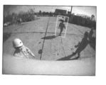
- FIG. 3 illustrates how the human image appears in the captured image behind the excavator captured by the rear camera 40B.
- the two captured images in FIG. 3 are examples of captured images of the rear camera 40B. 3 represents the presence of a human image, and is not displayed in an actual captured image.
- the periphery monitoring system 100 promotes identification of a human image included in the target image by normalizing the target image.
- “normalization” means that the target image is converted into an image having a predetermined size and a predetermined shape.
- a target image that can take various shapes in a captured image is converted into a rectangular image of a predetermined size by projective conversion.
- the projective transformation for example, an 8-variable projective transformation matrix is used.
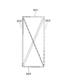
- FIG. 4 is a schematic diagram illustrating an example of a geometric relationship used when the extraction unit 31 cuts out a target image from a captured image.
- the box BX in FIG. 4 is a virtual solid object in real space, and is a virtual rectangular parallelepiped defined by eight vertices A to H in this embodiment.
- the point Pr is a reference point set in advance for referring to the target image.
- the reference point Pr is a point set in advance as an assumed standing position of a person, and is located at the center of a quadrilateral ABCD defined by four vertices A to D.
- the size of the box BX is set based on the direction of the person, the stride, the height, and the like.
- the rectangle ABCD and the rectangle EFGH are squares, and the length of one side is, for example, 800 mm.
- the height of the rectangular parallelepiped is, for example, 1800 mm. That is, the box BX is a rectangular parallelepiped having a width of 800 mm, a depth of 800 mm, and a height of 1800 mm.
- the quadrangle ABGH defined by the four vertices A, B, G, and H forms a virtual plane region TR corresponding to the region of the target image in the captured image. Further, the quadrangle ABGH as the virtual plane region TR is inclined with respect to the virtual ground that is a horizontal plane.
- FIG. 5 is a top view of the real space behind the shovel, and shows the positional relationship between the rear camera 40B and the virtual plane regions TR1 and TR2 when the virtual plane regions TR1 and TR2 are referenced using the reference points Pr1 and Pr2.
- the reference point Pr can be arranged at each of the lattice points of the virtual grid on the virtual ground.
- the reference points Pr may be irregularly arranged on the virtual ground, or may be arranged at equal intervals on a line segment radially extending from the projection point of the rear camera 40B on the virtual ground. For example, each line segment extends radially in increments of 1 degree, and the reference points Pr are arranged at intervals of 100 mm on each line segment.
- the first surface of the box BX defined by the quadrangle ABFE (see FIG. 4) is positive to the rear camera 40B when the virtual plane region TR1 is referenced using the reference point Pr1. It arranges so that it may be. That is, the line segment connecting the rear camera 40B and the reference point Pr1 is orthogonal to the first surface of the box BX arranged in association with the reference point Pr1 when viewed from above. Similarly, the first surface of the box BX is arranged to face the rear camera 40B even when the virtual plane region TR2 is referenced using the reference point Pr2.
- a line segment connecting the rear camera 40B and the reference point Pr2 is orthogonal to the first surface of the box BX arranged in association with the reference point Pr2 when viewed from above. This relationship holds even when the reference point Pr is arranged on any lattice point. That is, the box BX is arranged so that the first surface thereof is always directly opposite the rear camera 40B.
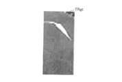
- FIG. 6A to 6C are diagrams showing a flow of processing for generating a normalized image from a captured image.
- FIG. 6A is an example of a captured image of the rear camera 40B, and displays a box BX arranged in association with the reference point Pr in real space.
- FIG. 6B is a diagram in which a region of the target image (hereinafter referred to as “target image region TRg”) in the captured image is cut out, and corresponds to the virtual plane region TR displayed in the captured image of FIG. 6A.
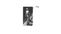
- FIG. 6C shows a normalized image TRgt obtained by normalizing the target image having the target image region TRg.
- the box BX arranged in the real space in relation to the reference point Pr1 determines the position of the virtual plane region TR in the real space, and on the captured image corresponding to the virtual plane region TR.
- a target image region TRg is defined.
- the extraction unit 31 can generate a normalized image TRgt having a predetermined size by normalizing the target image having the target image region TRg.
- the size of the normalized image TRgt is, for example, 64 pixels long ⁇ 32 pixels wide.
- FIG. 7A1 to FIG. 7C2 are diagrams showing the relationship among the captured image, the target image region, and the normalized image.
- FIG. 7A1 shows the target image region TRg3 in the captured image
- FIG. 7A2 shows the normalized image TRgt3 of the target image having the target image region TRg3.
- 7B1 shows the target image region TRg4 in the captured image
- FIG. 7B2 shows the normalized image TRgt4 of the target image having the target image region TRg4.
- FIG. 7C1 shows the target image region TRg5 in the captured image
- FIG. 7C2 shows the normalized image TRgt5 of the target image having the target image region TRg5.
- the target image region TRg5 in the captured image is larger than the target image region TRg4 in the captured image. This is because the distance between the virtual plane area corresponding to the target image area TRg5 and the rear camera 40B is smaller than the distance between the virtual plane area corresponding to the target image area TRg4 and the rear camera 40B.
- the target image region TRg4 in the captured image is larger than the target image region TRg3 in the captured image. This is because the distance between the virtual plane area corresponding to the target image area TRg4 and the rear camera 40B is smaller than the distance between the virtual plane area corresponding to the target image area TRg3 and the rear camera 40B. That is, the target image area in the captured image is smaller as the distance between the corresponding virtual plane area and the rear camera 40B is larger.
- the normalized images TRgt3, TRgt4, and TRgt5 are all rectangular images having the same size.
- An image portion (hereinafter referred to as a “leg image portion”) estimated to be a leg portion of the human candidate image is arranged in the region. Further, the extraction unit 31 can acquire the normalized image in a state where the inclination (image collapse) of the human candidate image with respect to the shape of the normalized image is suppressed.
- the identification processing inappropriate area is a known area where no human image can exist, for example, an area in which the excavator's vehicle body is reflected (hereinafter referred to as “vehicle body reflection area”), an area that protrudes from the captured image ( Hereinafter, it is referred to as “extrusion area”).
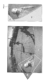
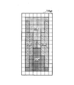
- FIG. 8 is a diagram illustrating the relationship between the target image area and the identification processing inappropriate area, and corresponds to FIGS. 7C1 and 7C2. Further, the right-slanted hatched area in the left diagram of FIG. 8 corresponds to the protrusion area R1, and the left-slanted hatched area corresponds to the vehicle body reflection area R2.
- the extraction unit 31 when the target image region TRg5 includes a part of the protrusion region R1 and the vehicle body reflection region R2, the extraction unit 31 has the target image region TRg5 after masking those identification processing inappropriate regions.
- a normalized image TRgt5 of the target image is generated. Note that the extraction unit 31 may mask the portion corresponding to the identification processing inappropriate region in the normalized image TRgt5 after generating the normalized image TRgt5.
- the right figure of FIG. 8 shows normalized image TRgt5. Further, in the right diagram of FIG. 8, the diagonally hatched area that falls to the right represents the mask area M1 corresponding to the protruding area R1, and the diagonally hatched area that falls to the left represents the mask area M2 corresponding to a part of the vehicle body reflection area R2. Represents.
- the extraction unit 31 performs mask processing on the image in the identification processing inappropriate region, thereby preventing the image in the identification processing inappropriate region from affecting the identification processing performed by the identification unit 32.
- the identification unit 32 can identify whether the image is a human image using an image of a region other than the mask region in the normalized image without being affected by the image of the identification processing inappropriate region.
- the extraction unit 31 may use any known method other than the mask process so that the image in the identification process inappropriate region does not affect the identification process performed by the identification unit 32.
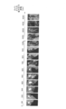
- FIG. 9 is a diagram illustrating an example of a normalized image.
- the 14 normalized images shown in FIG. 9 include images of human candidates that are closer to the rear camera 40B as the normalized image is closer to the left end of the diagram, and the normalized image closer to the right end of the diagram is It includes images of human candidates that are located far from the rear camera 40B.
- the extraction unit 31 performs any normalization regardless of the rear horizontal distance (the horizontal distance in the Y-axis direction shown in FIG. 5) between the virtual plane region TR and the rear camera 40B in the real space.
- the head image portion, the torso image portion, the leg image portion, and the like can be arranged at substantially the same ratio. Therefore, the extraction unit 31 can reduce the calculation load when the identification unit 32 executes the identification process, and can improve the reliability of the identification result.
- the above-described rear horizontal distance is an example of information regarding the positional relationship between the virtual plane region TR and the rear camera 40B in the real space, and the extraction unit 31 adds the information to the extracted target image. Further, the information on the positional relationship described above includes a top view angle with respect to the optical axis of the rear camera 40B of a line segment connecting the reference point Pr corresponding to the virtual plane region TR and the rear camera 40B.
- the periphery monitoring system 100 generates the normalized image TRgt from the target image region TRg corresponding to the virtual plane region TR that faces the direction of the imaging device 40 and is inclined with respect to the virtual ground that is a horizontal plane. Therefore, normalization in consideration of how the person looks in the height direction and depth direction can be realized. As a result, even when a captured image of the imaging device 40 attached to the construction machine so as to capture an image of a person from above is used, a person existing around the construction machine can be detected more reliably. In particular, even when a person approaches the imaging device 40, a normalized image can be generated from a target image that occupies a sufficiently large area on the captured image, so that the person can be reliably detected.
- the periphery monitoring system 100 defines the virtual plane region TR as a rectangular region formed by the four vertices A, B, G, and H of the box BX that is a virtual rectangular parallelepiped in real space. Therefore, the reference point Pr in the real space and the virtual plane region TR can be geometrically associated with each other, and further, the virtual plane region TR in the real space and the target image region TRg in the captured image can be geometrically associated with each other. Can do.
- the extraction unit 31 performs mask processing on the image of the identification processing inappropriate region included in the target image region TRg. Therefore, the identification unit 32 can identify whether the image is a human image by using an image of a region other than the mask region in the normalized image without being affected by the image of the identification inappropriate region including the vehicle body reflection region R2.
- the extraction unit 31 can extract a target image for each reference point Pr.
- Each of the target image regions TRg is associated with one of the reference points Pr that is set in advance as a person's assumed standing position via the corresponding virtual plane region TR. Therefore, the periphery monitoring system 100 can extract a target image that is likely to include a human candidate image by extracting the reference point Pr that is likely to be present by an arbitrary method. In this case, it is possible to prevent the target image having a low possibility of including the human candidate image from being subjected to the identification processing by the image processing with a relatively large calculation amount, and to realize the high-speed human detection processing.
- FIG. 10 is a schematic diagram illustrating an example of a geometric relationship used when the extraction unit 31 cuts out a target image from a captured image, and corresponds to FIG.
- FIG. 11 is a diagram illustrating an example of a feature image in a captured image.
- the feature image is an image that represents a characteristic part of a person, and is preferably an image that represents a part in which the height from the ground in real space is difficult to change. Therefore, the feature image includes, for example, an image of a helmet, an image of a shoulder, an image of a head, an image of a reflector or a marker attached to a person, and the like.
- the helmet has a feature that its shape is approximately a sphere, and when the projected image is projected onto the captured image, it is always nearly circular regardless of the imaging direction.
- the helmet has a hard surface and is glossy or semi-glossy, and when the projected image is projected on the captured image, a local high-intensity region and a radial luminance gradient centered on the region are generated. It has the feature of being easy. Therefore, the helmet image is particularly suitable as a feature image.
- the feature that the projected image is close to a circle, the feature that it is easy to generate a radial brightness gradient centered on a local high brightness area, etc. are used for image processing to find the helmet image from the captured image. May be.
- the image processing for finding the helmet image from the captured image includes, for example, luminance smoothing processing, Gaussian smoothing processing, luminance maximum point searching processing, luminance minimum point searching processing, and the like.
- the extraction unit 31 finds out a helmet image (an image that can be estimated to be a helmet strictly) in the captured image by the pre-stage image recognition process. This is because a person working around the excavator is considered to be wearing a helmet. Then, the extraction unit 31 derives the most relevant reference point Pr from the position of the found helmet image. Then, the extraction unit 31 extracts a target image corresponding to the reference point Pr.
- a helmet image an image that can be estimated to be a helmet strictly
- the extraction unit 31 derives the most relevant reference point Pr from the position of the found helmet image.
- the extraction unit 31 extracts a target image corresponding to the reference point Pr.
- the extraction unit 31 uses the geometric relationship shown in FIG. 10 to derive a highly relevant reference point Pr from the position of the helmet image in the captured image.
- the geometric relationship in FIG. 10 is different from the geometric relationship in FIG. 4 in that the virtual head position HP in the real space is determined, but is common in other points.
- the virtual head position HP represents the head position of a person assumed to be present on the reference point Pr, and is arranged immediately above the reference point Pr. In this embodiment, it is arranged at a height of 1700 mm on the reference point Pr. Therefore, if the virtual head position HP in the real space is determined, the position of the reference point Pr in the real space is uniquely determined, and the position of the virtual plane region TR in the real space is also uniquely determined. Further, the target image region TRg in the captured image is also uniquely determined. Then, the extraction unit 31 can generate a normalized image TRgt having a predetermined size by normalizing the target image having the target image region TRg.
- the head image position AP can be set in advance in association with each of the preset reference points Pr.
- the head image position AP may be derived from the reference point Pr in real time.
- the extraction unit 31 searches for the helmet image in the captured image of the rear camera 40B by the pre-stage image recognition process.
- the upper part of FIG. 11 shows a state where the extraction unit 31 has found the helmet image HRg. And the extraction part 31 determines the representative position RP, when the helmet image HRg is found.
- the representative position RP is a position derived from the size, shape, etc. of the helmet image HRg. In this embodiment, the representative position RP is the position of the central pixel in the helmet image area including the helmet image HRg.
- the lower diagram in FIG. 11 is an enlarged view of the helmet image region that is a rectangular image region partitioned by white lines in the upper diagram in FIG.
- the extraction unit 31 derives a head image position AP that is closest to the representative position RP using, for example, a nearest neighbor search algorithm.
- a nearest neighbor search algorithm For example, six head image positions AP1 to AP6 are preset in the vicinity of the representative position RP, and the head image position AP5 is the head image position AP closest to the representative position RP. It shows that.
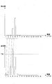
- FIG. 16A to 16C are conceptual diagrams showing the relationship between the normalized image TRgt as the target image and the weak classifier.
- FIG. 16A shows a state in which a normalized image TRgt of 64 vertical pixels ⁇ 32 horizontal pixels is divided into 128 HOG blocks of 16 vertical blocks ⁇ 8 horizontal blocks.
- FIG. 16B shows a state in which the central 84 HOG blocks of the normalized image TRgt are divided into four sections SC1 to SC4.
- the normalized image TRgt is divided into four sections SC1 to SC4 by two diagonal lines.
- FIG. 16C shows another configuration example of the four sections SC1 to SC4.
- the combination of the extraction unit 31, the identification unit 32, and the tracking unit 33 constitutes a human detection unit 34 that detects whether or not there is a person around the shovel based on the captured image of the imaging device 40. .
- the human detection unit 34 may discriminate and recognize at least two stages of the human detection state and the human non-detection state. For example, a state in which at least one of a condition regarding distance and a condition regarding reliability is satisfied is determined as a first person detection state (warning state), and a state where both are satisfied is determined as a second person detection state (alarm). State).
- the condition regarding the distance includes, for example, that the distance from the excavator at the actual position of the person shown in the image identified as the human image is less than a predetermined value.
- the condition relating to reliability includes, for example, identification of a person image of the same person in four out of six consecutive identification results.
- the control unit 35 is a functional element that controls various devices.
- the control unit 35 controls various devices in accordance with an operator input via the input device 41.
- the display image displayed on the screen of the in-vehicle display is switched according to an image switching command input through the touch panel.
- the display image includes a through image of the rear camera 40B, a through image of the right side camera 40R, a through image of the left side camera 40L, a viewpoint conversion image, and the like.
- the viewpoint conversion image is, for example, a bird's-eye view image (image viewed from a virtual viewpoint directly above the shovel) synthesized from images captured by a plurality of cameras.
- the control unit 35 returns the shovel state to the first state when a predetermined release condition is satisfied after the shovel state is set to the second state. That is, when a predetermined release condition is satisfied after restricting or stopping the shovel movement, the restriction or stop is released.
- the predetermined release condition includes, for example, “determining that there is no person within a predetermined range around the excavator” (hereinafter referred to as “first release condition”). Further, the predetermined release condition additionally includes, for example, “a state in which the excavator does not start” is secured (hereinafter referred to as “second release condition”). Further, the predetermined release condition may include “the operator confirming that there is no person in the vicinity of the excavator” (hereinafter referred to as “third release condition”). In the present embodiment, whether or not the excavator's movement is restricted or stopped, and whether or not each of the first release condition, the second release condition, and the third release condition is satisfied is managed using a flag.
- the operator's limbs are separated from the operating device is based on, for example, a captured image of a camera that images the driver's cab, an output of an electrostatic sensor attached to the operating device (for example, a grip of the operating lever), or the like.
- the control unit 35 detects this.
- “The predetermined button operation has been performed” means, for example, that a confirmation button (for example, a horn button or the same) is displayed in a state where a message such as “Are the excavator not moving? When the software button (displayed on the screen) is pressed, the control unit 35 detects.
- the control unit 35 may determine that “the state where the excavator does not start is secured” when a release operation by the operator such as an operation input to a lever, button, panel, or the like in the driver's seat is performed, for example. .
- the third release condition is satisfied, for example, when the confirmation button is pressed while a message such as “Have you confirmed that there are no people around the excavator?” Is displayed on the screen of the in-vehicle display. Note that the third release condition may be omitted.
- the control unit 35 outputs a control command to the in-vehicle display as the output device 50, and displays a captured image including the human image that caused the cause.
- a human image is included only in the captured image of the left side camera 40L
- the through image of the left side camera 40L may be displayed alone.
- the through images of the two cameras may be displayed side by side, and the captured images of the two cameras may be displayed simultaneously.
- One synthesized image for example, a viewpoint conversion image
- control unit 35 determines whether or not there is a person around the excavator (step ST21). In the present embodiment, the control unit 35 determines whether or not there is a person around the shovel based on the final human detection result of the tracking unit 33.
- control unit 35 outputs a control command to the in-vehicle speaker as the output device 50 to output a second alarm.
- a control command is output to an in-vehicle display as the output device 50 to display a captured image including a human image that has caused a restriction or stop.
- step ST23 When it is determined that the excavator movement has already been restricted or stopped (YES in step ST23), the control unit 35 performs a process for releasing the restriction or stop (hereinafter, referred to as “restriction release process”). Execute (step ST24).
- the control unit 35 determines whether or not the first release condition is satisfied (step ST31). In the present embodiment, the control unit 35 determines whether or not there is a person within a predetermined range around the excavator. Specifically, it is determined whether or not the current person detection state has escaped from the second person detection state (alarm state). It may be determined whether the first person detection state (warning state) and the second person detection state (warning state) have been removed.
- the control unit 35 determines whether the third release condition is satisfied (step ST33). In the present embodiment, the control unit 35 determines whether or not the operator has confirmed that there is no person around the excavator. Specifically, it is determined whether or not the confirmation button has been pressed in a state where a message such as “Did you confirm that there are no people around the shovel?” Is displayed on the screen of the in-vehicle display.
- control unit 35 outputs a control command to the in-vehicle speaker as the output device 50 to stop the output of the second alarm. Moreover, a control command is output to the vehicle-mounted display as the output device 50, and the display of the captured image including the human image that has caused the restriction or stop is stopped. For example, the through image displayed before the second alarm is output is displayed again. Further, the control unit 35 may display a message notifying that the restriction or stop of the excavator movement has been released.
- the controller 30 determines that there is no person around the shovel after restricting or stopping the shovel movement, the controller 30 only determines that the state where the shovel does not start is secured.
- the restriction or suspension can be lifted.
- the controller 30 can release the restriction or stop only when it is determined that the state where the shovel does not start is secured and it is determined by the operator that there is no person around the shovel. Therefore, the controller 30 can prevent the shovel from starting unintentionally when the restriction or stop is released.
- the controller 30 detects a person existing on the right rear side of the excavator. However, since the person's real position is beyond the first distance, the controller 30 does not highlight the person's image and does not output the first alarm. However, the controller 30 may highlight the person's image, such as displaying the outline of the corresponding target image region TRg as a white frame, and may output a first alarm. Further, a message such as “peripheral monitoring process in progress” may be displayed regardless of whether or not a person has already been detected. This is because the operator can recognize that the peripheral monitoring process is being executed.
- the controller 30 detects a person who is present within the first distance on the right rear side of the excavator and beyond the second distance. Therefore, the controller 30 highlights the person's image and outputs the first alarm. Specifically, the controller 30 displays the outline of the corresponding target image region TRg as a yellow frame F1 in the camera image portion G1. In the indicator portion G2, a region A4 corresponding to the person's actual position is displayed in yellow. However, the display of the yellow frame may be omitted. Moreover, you may display the message which tells that it is a 1st person detection state (warning state).
- the controller 30 detects a person existing within the second distance on the right rear side of the excavator. Therefore, the controller 30 highlights the person's image and outputs a second alarm. Specifically, the controller 30 displays the outline of the corresponding target image region TRg as a red frame F2 in the camera image portion G1. In the indicator portion G2, a region B2 corresponding to the person's actual position is displayed in red. In addition, the controller 30 restricts the movement of the shovel, and blinks a message “Excavator operation is being restricted” indicating that the second person detection state (alarm state) has occurred. However, the display of the message indicating that the second person detection state (alarm state) is present may be omitted.
- the spread angle of each of the areas A1 to A6 is 45 degrees, and the spread angle of each of the areas B1 to B3 is 90 degrees.
- This difference in the spread angle is based on a difference in properties between the first person detection state (warning state) and the second person detection state (warning state).
- the first person detection state is a state in which a preliminary alarm is output with low accuracy but quick response, and a relatively wide space range that is relatively far from the excavator is monitored. It is a range. For this reason, when the spread angle of the areas A1 to A6 is increased, the monitoring range corresponding to each area is increased together with the display range, and it becomes difficult to understand the actual position of the person who caused the first alarm.
- the second person detection state is a state in which a formal alarm with high accuracy but slow response is output, and a relatively narrow space range relatively close to the excavator is a monitoring range. Yes. Therefore, if the expansion angle of the areas B1 to B3 is reduced, the monitoring range corresponding to each area is reduced together with the display range, and it is difficult to know in which direction the person who caused the second alarm is located. End up. This is because the display range is small and difficult to see. Therefore, desirably, as shown in FIGS. 21A to 21C, the spread angles of the regions A1 to A6 are set to be smaller than the spread angles of the regions B1 to B3.
- 21A to 21C illustrate a case where a human image is detected in the captured image of the rear camera 40B when the through image of the rear camera 40B is displayed.
- the above description is similarly applied to a case where a human image is detected in at least one of the left camera 40L and the right camera 40R when a through image of the rear camera 40B is displayed.
- the output image displayed on the camera image portion G1 may be automatically switched from a through image of the rear camera 40B to a viewpoint conversion image synthesized from a through image of another camera or captured images of a plurality of cameras. Good.
- the controller 30 outputs the output image displayed on the camera image portion G1 to the left camera 40L.
- the through image may be switched to.
- the controller 30 displays the output image including the camera image portion G1 and the excavator icon CG1 generated using the captured image of the rear camera 40B attached to the excavator on the in-vehicle display.
- the image portions regions A1 to A6 and regions B1 to B3 around the excavator icon CG1, the image portion (region A4 in FIG. 21B, corresponding to the direction in which the person is detected detected by the human detection unit 34).
- FIG. 22 is a correspondence table showing a correspondence relationship between detection states and display colors of frames and regions.
- the outline of the target image region corresponding to the human image that caused the alert state is displayed as a yellow frame, and any of the regions A1 to A6 is displayed. Is displayed in yellow.
- the outline of the target image area corresponding to the human image that caused the alarm state is displayed as a red frame, and any of the areas B1 to B3 is displayed. Is displayed in red.
- the fourth line shows that when the detection state is a warning state and an alarm state, a contour line corresponding to the human image that causes the warning state is displayed in a yellow frame and causes the alarm state. It represents that the outline corresponding to the human image is displayed with a red frame. In addition, the area corresponding to the human image causing the warning state in the areas A1 to A6 is displayed in yellow, and the area corresponding to the human image causing the alarm state in the areas B1 to B3 is red. Indicates that it is displayed.
- the controller 30 outputs an alarm and highlights the image portion of the person when it is determined that there is a person around the excavator. Therefore, the operator can confirm the person who caused the alarm on the screen. In addition, when an error occurs, the operator can check on the screen what is the cause of the error.
- the controller 30 displays a frame image as a human detection marker on the camera image portion G1 for the first time when the first person detection state (warning state) is entered, and changes the color of the corresponding region of the indicator portion G2.
- the frame image is displayed as the human detection marker, but another emphasized image such as a reverse display image may be adopted as the human detection marker.
- FIG. 23 shows an example of an output image when the first person detection state and the second person detection state coexist.
- the output image of FIG. 23 includes a viewpoint conversion image portion G3 corresponding to the camera image portion G1 of FIGS. 21A to 21C.
- a portion corresponding to the indicator portion G2 in FIGS. 21A to 21C is integrated into the viewpoint converted image portion G3.
- the shovel icon CG1 in FIGS. 21A to 21C corresponds to the shovel icon CG2 in FIG. 23, and the areas A1 to A6 in FIGS. 21A to 21C correspond to the areas C1 to C6 in FIG. 21A to 21C corresponds to the combination of regions C1 and C2 in FIG. 23, and region B2 in FIGS.
- 21A to 21C corresponds to the combination of regions C3 and C4 in FIG.
- a region B3 of 21C corresponds to a combination of the regions C5 and C6 of FIG.
- a line segment L3 superimposed and displayed on the viewpoint conversion image indicates that the distance from the excavator is a predetermined third distance (for example, 2.5 meters).
- the controller 30 detects a person who is within a first distance (for example, 5 meters) on the left side of the excavator and beyond a third distance (the person who caused the first person detection state). Detected. Moreover, the person (person who caused the 2nd person detection state) which exists within the 3rd distance behind a shovel is detected. Therefore, the controller 30 highlights the images of those persons, outputs a second alarm, and restricts the movement of the shovel. Specifically, the controller 30 displays a yellow circle MA1 as a human detection marker at the position of the reference point Pr corresponding to the person who caused the first person detection state, and an area corresponding to the position C2 is displayed in yellow.
- a first distance for example, 5 meters
- a red circle MA2 as a human detection marker is displayed at the position of the reference point Pr corresponding to the person who caused the second person detection state, and the combination of the regions C3 and C4 corresponding to the position is red. Is displayed. Further, the controller 30 may cause the excavator to limit the movement of the shovel, and blink the message “Excavator operation being restricted” indicating that the second person detection state (alarm state) is present. Further, the display of the yellow circle MA1 may be omitted. This is to make the screen easier to see.
- the controller 30 includes the viewpoint conversion image portion G3 and the shovel icon CG2 that are generated using the captured images of the rear camera 40B, the left camera 40L, and the right camera 40R attached to the shovel.
- the output image is displayed on the in-vehicle display.
- the controller 30 can display the image part on the output image corresponding to the person detected by the person detection unit 34 so that the operator can distinguish it from other image parts. Specifically, it can be displayed so that the operator can distinguish whether a person exists, whether it is near or far, and in which direction the person is present when viewed from the shovel.
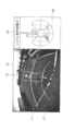
- FIG. 24 is an example of an output image including a viewpoint conversion image generated based on captured images of the rear camera 40B, the left camera 40L, and the right camera 40R.
- FIG. 24 shows an example of an output image when the first person detection state and the second person detection state coexist as in the case of FIG.
- the output image of FIG. 24 includes an indicator portion G2 and a viewpoint conversion image portion G3.
- a partial rectangular outer peripheral line L2g drawn around the excavator icon CG1 indicates that the distance from the excavator is a predetermined third distance (for example, 2.5 meters), and corresponds to the line segment L3 of the viewpoint conversion image portion G3. .
- the controller 30 detects a person who is within a first distance (for example, 5 meters) on the left side of the excavator and beyond a third distance (the person who caused the first person detection state). Detected. Moreover, the person (person who caused the 2nd person detection state) which exists within the 3rd distance behind a shovel is detected. Therefore, the controller 30 highlights the images of those persons, outputs a second alarm, and restricts the movement of the shovel. Specifically, the controller 30 displays a yellow circle MA1 as a human detection marker at the position of the reference point Pr corresponding to the person who caused the first person detection state, and an indicator corresponding to the position. A region A2 of the portion G2 is displayed in yellow.
- a first distance for example, 5 meters
- the controller 30 displays a yellow circle MA1 as a human detection marker at the position of the reference point Pr corresponding to the person who caused the first person detection state, and an indicator corresponding to the position.
- a region A2 of the portion G2 is displayed in yellow.
- a red circle MA2 as a human detection marker is displayed at the position of the reference point Pr corresponding to the person who caused the second person detection state, and the area B2 of the indicator portion G2 corresponding to the position is displayed in red. Is displayed.
- the controller 30 restricts the movement of the shovel, and blinks a message “Excavator operation is being restricted” indicating that the second person detection state (alarm state) has occurred. Note that the display of the yellow circle MA1 may be omitted. This is to make the screen easier to see.
- the controller 30 can achieve the same effect as when the output images of FIGS. 21A to 21C are displayed.
- the controller 30 restricts or stops the movement of the shovel and displays the image of the person. If it is determined that there is no person around the excavator after the excavator is restricted or stopped, the restriction or stop is limited only when it is determined that the excavator does not start moving. It is determined that it can be released. And when the predetermined waiting time elapses, the restriction or stop is actually released. Therefore, it is possible to more appropriately cancel the shovel operation restriction executed in response to human detection.
- the controller 30 can output an alarm toward the operator from the side where the person who caused the shovel exists. Therefore, it is possible to make the operator recognize the direction in which the person exists before the operator looks at the screen of the in-vehicle display. The operator can visually confirm that a person is present in the recognized direction by visually recognizing the direction in which the person is present according to the direction in which the alarm is heard, and then looking at the on-vehicle display screen. . As described above, the controller 30 informs the operator of the direction in which the person is present by cooperation between the alarm and the display, so that the operator can recognize the situation around the shovel in a short time.
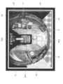
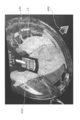
- FIG. 25A to FIG. 25E is an example of an output image including a peripheral monitoring image as a viewpoint conversion image generated based on a plurality of captured images.
- a line segment L3 drawn around the excavator icon CG2 indicates that the distance from the excavator is a predetermined third distance (for example, 2.5 meters).
- the periphery monitoring image is obtained by projecting the captured images of the rear camera 40B, the left side camera 40L, and the right side camera 40R onto a space model, and then projecting the projection image projected onto the space model into another image. It is an image obtained by reprojecting on a two-dimensional plane.
- the “space model” is a projection target of the captured image in the virtual space, and is configured by one or a plurality of planes or curved surfaces including a plane or curved surface other than the plane on which the peripheral monitoring image is located.
- the control unit 35 outputs a control command to a display device serving as the output device 50, and relatively enlarges and displays a part of the periphery monitoring image displayed on the screen of the display device.
- the control unit 35 locally enlarges and displays a specific image portion of the periphery monitoring image displayed on the screen of the display device.
- the control unit 35 locally enlarges and displays a specific image portion in the periphery monitoring image by generating and displaying an image when the periphery monitoring image in the virtual space is viewed from a different virtual viewpoint.
- the specific image portion is, for example, an image portion having high importance such as an image portion to be noticed by an operator of the excavator, and is hereinafter also referred to as “attention image portion”.
- the direction of the target image portion viewed from the shovel is one, and image portions in two or more directions are not simultaneously adopted as the target image portion.
- the present invention does not exclude that image portions in two or more directions are simultaneously employed as the attention image portion.
- the direction of the target image portion viewed from the shovel may be limited to the directions of the six regions A1 to A6 shown in FIG. 21A, or may be limited to the directions of the three regions B1 to B3.
- the size and shape of the attention image portion may be fixed or dynamically determined.
- “Locally enlarged display” means, for example, that the attention image portion of the peripheral monitoring image is partially enlarged and displayed while maintaining a smooth connection with other image portions.
- the control unit 35 locally enlarges and displays the image portion of interest in the peripheral monitoring image while displaying substantially the entire depth of the peripheral monitoring image by loupe processing, projection conversion, scale conversion, and the like.
- the attention image part is, for example, an image part corresponding to a position where it is determined that a person exists in real space, an image part corresponding to a space in the traveling direction of the lower traveling body 1, or a space behind the upper swing body 3. Corresponding image portion or the like.
- the process of locally enlarging the target image portion while displaying substantially the entire peripheral monitoring image is referred to as “local enlargement process”.
- “Substantially the entire periphery monitoring image” means that the periphery of the periphery monitoring image may protrude from the screen.
- the image of the person included in the attention image portion displayed locally enlarged is larger than a predetermined size. Is displayed. For example, an image of a person within a predetermined distance (for example, 12 m) from the excavator is displayed on the screen of the display device so as to be larger than a predetermined size (for example, 7 mm ⁇ 7 mm).
- FIG. 25A shows an output image including a peripheral monitoring image before the local enlargement process is executed.
- the output image of FIG. 25A shows a situation where the worker W1 exists within the third distance behind the excavator.
- FIG. 25B shows an example of an output image including a peripheral monitoring image after the local enlargement process is executed.
- the output image of FIG. 25B shows a situation where the worker W1 exists within the third distance behind the excavator as in the case of FIG. 25A.
- the control unit 35 executes a local enlargement process when the person detection unit 34 detects a person.
- the control unit 35 employs an image portion corresponding to the position in the real space of the person detected by the human detection unit 34 as the attention image portion.
- the peripheral monitoring image is rotated in the screen so that the attention image portion is located at the lower center of the screen, and the attention image portion is locally enlarged.
- the rotation of the periphery monitoring image is executed, for example, using the center of the periphery monitoring image corresponding to the turning center of the excavator as a rotation axis.
- the rotation of the peripheral monitoring image and the enlargement of the target image portion are in no particular order. Further, rotation of the periphery monitoring image may be omitted. Further, the image portion other than the attention image portion may be reduced. For example, the image portion that is farther from the target image portion may be reduced so as to be displayed smaller.
- the control unit 35 When a plurality of people are detected around the excavator, the control unit 35 employs an image portion corresponding to the position of the person existing closest to the excavator as the attention image portion. Alternatively, the control unit 35 calculates the risk in each direction viewed from the shovel based on the detected distance between the person and the excavator, the direction of the lower traveling body 1, the direction of the upper swing body 3, and the like. You may employ
- the control unit 35 may execute the local enlargement process when the first person detection state (warning state) caused by the worker W1 is brought about, and the second person detection caused by the worker W1 is caused. Local enlargement processing may be performed when a condition (alarm condition) occurs.
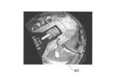
- FIG. 25C shows another example of the output image including the periphery monitoring image after the local enlargement process is executed.
- the output image of FIG. 25C shows a situation where the worker W2 exists within the third distance on the left side of the excavator.
- the control unit 35 employs an image portion corresponding to the position in the real space of the person detected by the human detection unit 34 as the attention image portion. Then, the peripheral monitoring image is rotated in the screen so that the attention image portion is located at the lower center of the screen, and the attention image portion is locally enlarged.
- control unit 35 may rotate the periphery monitoring image within the screen according to the movement of the worker W2 so that the image of the worker W2 being moved is always located at the lower center of the screen. That is, the periphery monitoring image may be rotated within the screen according to a change in the display position of the attention image portion. This is to cancel the change in the display position of the target image portion.
- FIG. 25D shows still another example of the output image including the peripheral monitoring image after the local enlargement process is executed.
- the output image of FIG. 25D shows a situation where the worker W2 exists within the third distance on the left side of the excavator as in the case of FIG. 25C.
- the output image of FIG. 25D is different from the output image of FIG. 25C in that a frame F3 is displayed around the image of the worker W2, but is common in other points.
- the control unit 35 may display an image for emphasizing the actual position of the worker W2 as in the frame F3. This is because the operator who views the output image can more easily recognize information related to the worker W2 (the presence / absence of the worker, the presence direction seen from the shovel, etc.).
- the control unit 35 rotates the periphery monitoring image in the screen according to the movement of the worker W2 so that the image of the moving worker W2 is always located in the frame F3. In this case, the position of the frame F3 is fixed. However, the control unit 35 may move the frame F3 according to the movement of the image of the worker W2 within the screen without rotating the periphery monitoring image within the screen.
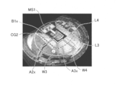
- FIG. 25E shows still another example of the output image including the peripheral monitoring image after the local enlargement process is executed.
- a line segment L4 drawn around the excavator icon CG2 indicates that the distance from the excavator is a predetermined fourth distance (for example, 5.0 meters).
- the output image of FIG. 25E shows a situation where the worker W3 exists within the fourth distance on the left side of the shovel and the worker W4 exists within the fourth distance behind the shovel.
- control unit 35 employs an image portion corresponding to the position of the worker W3 closest to the excavator as the attention image portion. Therefore, the control unit 35 locally enlarges the attention image portion including the image of the worker W3, and rotates the periphery monitoring image within the screen so that the attention image portion is located at the lower center of the screen. .
- the control unit 35 displays the outline of the area B1x with a solid line.
- the solid line color indicates that the worker W3 causes the second person detection state (warning state).
- FIG. 25E shows the boundary of the region B1x with a broken line for convenience of explaining the position of the region B1x, but this broken line is not actually displayed.
- the control unit 35 employs the image portion corresponding to the position in the real space of the person detected by the human detection unit 34 as the attention image portion. Then, the attention image portion can be made conspicuous by locally expanding and displaying the attention image portion. Therefore, the operator who sees the output image including the peripheral monitoring image after the local enlargement process is executed can recognize at a glance information related to the worker W1 (the presence / absence of the worker, the presence direction seen from the shovel, etc.). . Further, the peripheral monitoring image can be rotated in the screen so that the attention image portion is always located at a specific portion (for example, the lower center) in the screen. Therefore, the operator can recognize information related to the worker W1 at a glance only by looking at a specific portion in the screen when an alarm or the like is output.
- the controller 30 displays the output image including the periphery monitoring image portion and the excavator icon CG2 on the in-vehicle display, and the person detected by the human detection unit 34 among the image portions around the excavator icon CG2.
- the image portion on the side corresponding to the presence direction of the image (for example, the image portion behind the shovel icon CG2 in FIG. 25B) is emphasized. Therefore, the controller 30 can display the image part on the output image corresponding to the person detected by the person detection unit 34 so that the operator can distinguish it from other image parts. Specifically, it can be displayed so that the operator can distinguish whether a person exists, whether it is near or far, and in which direction the person is present when viewed from the shovel.
- FIG. 26A and FIG. 26B is an example of an output image including a peripheral monitoring image generated based on three captured images, similar to each of FIG. 25A to FIG. 25E.
- control unit 35 performs local enlargement processing when a person is not detected around the excavator and when the traveling lever is operated. Further, when a person is detected after executing the local enlargement process according to the operation of the traveling lever, the control unit 35 adopts an image part corresponding to the detected position in the real space as the attention image part. The local enlargement process is executed after reworking. However, the control unit 35 may continue the local enlargement process being executed when a person is detected after executing the local enlargement process in accordance with the operation of the travel lever.
- control unit 35 may execute the local enlargement process when no person is detected around the excavator and the traveling lever is not operated.
- control unit 35 may employ, for example, an image portion corresponding to a space behind the upper swing body 3 as the attention image portion. Or you may employ
- FIG. 26A shows an example of an output image including a peripheral monitoring image after the local enlargement process is executed according to the operation of the traveling lever.
- the output image of FIG. 26A shows a situation in which the lower traveling body 1 travels diagonally rightward with respect to the upper swing body 3.
- the control unit 35 employs an image portion corresponding to a space in the traveling direction of the lower traveling body 1 as the attention image portion.
- the traveling direction of the lower traveling body 1 is derived from, for example, the turning angle of the upper swing body 3 with respect to the lower traveling body 1. This is because the traveling direction of the lower traveling body 1 can be uniquely determined based on the longitudinal direction of the upper swing body 3.
- the traveling direction of the lower traveling body 1 includes a pair of azimuth sensors attached to the lower traveling body 1 and the upper revolving body 3, an angular velocity sensor such as a gyroscope attached to the upper revolving body 3, turning It is derived based on the output of a rotation angle sensor such as a resolver and a rotary encoder attached to the mechanism 2.
- a rotation angle sensor such as a resolver and a rotary encoder attached to the mechanism 2.
- the excavator blind spot area is imaged using three cameras, but the excavator blind spot area may be imaged using one, two, or four or more cameras.
- human detection is performed using an image captured by the imaging device 40, but human detection is performed using outputs from an ultrasonic sensor, a laser radar, a pyroelectric sensor, a millimeter wave radar, and the like. Also good.
- the human detection process is individually applied to each of the plurality of captured images.
- the human detection process is applied to one composite image generated from the plurality of captured images. Also good.
- head HP ... virtual head position HRg ... helmet image M1, M2 ... mask area Pr, Pr1, Pr2, Pr10 to Pr12 ... reference point R1 ... extrusion area R2 ... body reflection area RP ... Representative position TR, TR1, TR2, TR10 to TR12 ... Virtual plane region TRg, TRg3, TRg4, TRg5 ... Target image region TRgt, TRgt3, TRgt4, TRgt5 ... Normalized image
Landscapes
- Engineering & Computer Science (AREA)
- Mining & Mineral Resources (AREA)
- Civil Engineering (AREA)
- General Engineering & Computer Science (AREA)
- Structural Engineering (AREA)
- Signal Processing (AREA)
- Multimedia (AREA)
- Physics & Mathematics (AREA)
- General Physics & Mathematics (AREA)
- Theoretical Computer Science (AREA)
- Image Analysis (AREA)
- Closed-Circuit Television Systems (AREA)
- Image Processing (AREA)
Abstract
周辺監視システム(100)は、ショベル周辺に存在する人を検知する人検知部(34)と、ショベルに搭載された出力装置(50)を制御する制御部(35)と、を備える。制御部(35)は、ショベルに取り付けられる撮像装置(40)の撮像画像を用いて生成される画像部分とショベルアイコンとを含む出力画像をディスプレイに表示し、且つ、ショベルアイコンの周辺にある画像部分のうち、人検知部(34)が検知した人の存在方向に対応する側の画像部分を強調する。
Description
本発明は、作業機械の周辺を監視する作業機械用周辺監視システムに関する。
ショベル周辺に存在する物体(人)を検知するセンサを備えたショベルが知られている(特許文献1参照。)。このショベルは、ショベルの右側で物体(人)を検知した場合に運転室内の右壁に設置されたスピーカから警報を出力させ、且つ、ショベルの右側を撮像するカメラのスルー画像をディスプレイに表示させる。また、ショベルの左側で物体(人)を検知した場合に運転室内の左壁に設置されたスピーカから警報を出力させ、且つ、ショベルの左側を撮像するカメラのスルー画像をディスプレイに表示させる。
しかしながら、上述のショベルは、センサが検知した物体(人)と、ディスプレイに表示された画像内の物体(人)とを対応付けていない。そのため、ディスプレイを見た操作者は、センサが検知した物体(人)が画像内の何れの物体(人)であるかを認識できないおそれがある。
上述に鑑み、作業機械によって検知された人が表示画像内のどの領域に存在するのかを操作者に容易に認識させることができる作業機械用周辺監視システムの提供が望まれる。
本発明の実施例に係る作業機械用周辺監視システムは、前記作業機械の周辺に存在する人を検知する人検知部と、前記作業機械に搭載された出力装置を制御する制御部と、を備え、前記制御部は、前記作業機械に取り付けられる撮像装置の撮像画像を用いて生成される画像部分と前記作業機械のアイコンとを含む出力画像を表示装置に表示し、且つ、前記アイコンの周辺にある画像部分のうち、前記人検知部が検知した人の存在方向に対応する側の画像部分を強調する。
上述の手段により、作業機械によって検知された人が表示画像内のどの領域に存在するのかを操作者に容易に認識させることができる作業機械用周辺監視システムが提供される。
図1は、本発明の実施例に係る周辺監視システム100が搭載される建設機械としてのショベルの側面図である。ショベルの下部走行体1には、旋回機構2を介して旋回自在に上部旋回体3が搭載される。上部旋回体3には、ブーム4が取り付けられる。ブーム4の先端にはアーム5が取り付けられ、アーム5の先端にはバケット6が取り付けられる。ブーム4、アーム5、及びバケット6は掘削アタッチメントを構成し、ブームシリンダ7、アームシリンダ8、及びバケットシリンダ9によりそれぞれ油圧駆動される。また、上部旋回体3には、キャビン10が設けられ、且つエンジン等の動力源が搭載される。また、上部旋回体3の上部には撮像装置40が取り付けられる。具体的には、上部旋回体3の後端上部、左端上部、右端上部に後方カメラ40B、左側方カメラ40L、右側方カメラ40Rが取り付けられる。また、キャビン10内にはコントローラ30及び出力装置50が設置される。
図2は、周辺監視システム100の構成例を示す機能ブロック図である。周辺監視システム100は、主に、コントローラ30、撮像装置40、及び出力装置50を含む。
コントローラ30は、ショベルの駆動制御を行う制御装置である。本実施例では、コントローラ30は、CPU及び内部メモリを含む演算処理装置で構成され、内部メモリに格納された駆動制御用のプログラムをCPUに実行させて各種機能を実現する。
また、コントローラ30は、各種装置の出力に基づいてショベルの周辺に人が存在するかを判定し、その判定結果に応じて各種装置を制御する。具体的には、コントローラ30は、撮像装置40及び入力装置41の出力を受け、抽出部31、識別部32、追跡部33、及び制御部35のそれぞれに対応するソフトウェアプログラムを実行する。そして、その実行結果に応じて機械制御装置51に制御指令を出力してショベルの駆動制御を実行し、或いは、出力装置50から各種情報を出力させる。なお、コントローラ30は、画像処理専用の制御装置であってもよい。
撮像装置40は、ショベルの周囲の画像を撮像する装置であり、撮像した画像をコントローラ30に対して出力する。本実施例では、撮像装置40は、CCD等の撮像素子を採用するワイドカメラであり、上部旋回体3の上部において光軸が斜め下方を向くように取り付けられる。
入力装置41は操作者の入力を受ける装置である。本実施例では、入力装置41は、操作装置(操作レバー、操作ペダル等)、ゲートロックレバー、操作装置の先端に設置されたボタン、車載ディスプレイに付属のボタン、タッチパネル等を含む。
出力装置50は、各種情報を出力する装置であり、例えば、各種画像情報を表示する車載ディスプレイ、各種音声情報を音声出力する車載スピーカ、警報ブザー、警報ランプ等を含む。本実施例では、出力装置50は、コントローラ30からの制御指令に応じて各種情報を出力する。
機械制御装置51は、ショベルの動きを制御する装置であり、例えば、油圧システムにおける作動油の流れを制御する制御弁、ゲートロック弁、エンジン制御装置等を含む。
抽出部31は、撮像装置40が撮像した撮像画像から識別処理対象画像を抽出する機能要素である。具体的には、抽出部31は、局所的な輝度勾配又はエッジに基づく簡易な特徴、Hough変換等による幾何学的特徴、輝度に基づいて分割された領域の面積又はアスペクト比に関する特徴等を抽出する比較的演算量の少ない画像処理(以下、「前段画像認識処理」とする。)によって識別処理対象画像を抽出する。識別処理対象画像(以下、「対象画像」とする。)は、後続の画像処理の対象となる画像部分(撮像画像の一部)であり、人候補画像を含む。人候補画像は、人画像である可能性が高いとされる画像部分(撮像画像の一部)である。
識別部32は、抽出部31が抽出した対象画像に含まれる人候補画像が人画像であるかを識別する機能要素である。具体的には、識別部32は、HOG(Histograms of Oriented Gradients)特徴量に代表される画像特徴量記述と機械学習により生成した識別器とを用いた画像認識処理等の比較的演算量の多い画像処理(以下、「後段画像認識処理」とする。)によって人候補画像が人画像であるかを識別する。識別部32が人候補画像を人画像として識別する割合は、抽出部31による対象画像の抽出が高精度であるほど高くなる。なお、識別部32は、夜間、悪天候時等の撮像に適さない環境下で所望の品質の撮像画像を得られない場合等においては、人候補画像の全てが人画像であると識別し、抽出部31が抽出した対象画像における人候補画像の全てを人であると識別してもよい。人の検知漏れを防止するためである。
次に、図3を参照し、後方カメラ40Bが撮像したショベル後方の撮像画像における人画像の見え方について説明する。なお、図3の2つの撮像画像は、後方カメラ40Bの撮像画像の例である。また、図3の点線円は人画像の存在を表し、実際の撮像画像には表示されない。
後方カメラ40Bは、ワイドカメラであり、且つ、人を斜め上から見下ろす高さに取り付けられる。そのため、撮像画像における人画像の見え方は、後方カメラ40Bから見た人の存在方向によって大きく異なる。例えば、撮像画像中の人画像は、撮像画像の左右の端部に近いほど傾いて表示される。これは、ワイドカメラの広角レンズに起因する像倒れによる。また、後方カメラ40Bに近いほど頭部が大きく表示される。また、脚部がショベルの車体の死角に入って見えなくなってしまう。これらは、後方カメラ40Bの設置位置に起因する。そのため、撮像画像に何らの加工を施すことなく画像処理によってその撮像画像に含まれる人画像を識別するのは困難である。
そこで、本発明の実施例に係る周辺監視システム100は、対象画像を正規化することで、対象画像に含まれる人画像の識別を促進する。なお、「正規化」は、対象画像を所定サイズ及び所定形状の画像に変換することを意味する。本実施例では、撮像画像において様々な形状を取り得る対象画像は射影変換によって所定サイズの長方形画像に変換される。なお、射影変換としては例えば8変数の射影変換行列が用いられる。
ここで、図4~図6Cを参照し、周辺監視システム100が対象画像を正規化する処理(以下、「正規化処理」とする。)の一例について説明する。なお、図4は、抽出部31が撮像画像から対象画像を切り出す際に用いる幾何学的関係の一例を示す概略図である。
図4のボックスBXは、実空間における仮想立体物であり、本実施例では、8つの頂点A~Hで定められる仮想直方体である。また、点Prは、対象画像を参照するために予め設定される参照点である。本実施例では、参照点Prは、人の想定立ち位置として予め設定される点であり、4つの頂点A~Dで定められる四角形ABCDの中心に位置する。また、ボックスBXのサイズは、人の向き、歩幅、身長等に基づいて設定される。本実施例では、四角形ABCD及び四角形EFGHは正方形であり、一辺の長さは例えば800mmである。また、直方体の高さは例えば1800mmである。すなわち、ボックスBXは、幅800mm×奥行800mm×高さ1800mmの直方体である。
4つの頂点A、B、G、Hで定められる四角形ABGHは、撮像画像における対象画像の領域に対応する仮想平面領域TRを形成する。また、仮想平面領域TRとしての四角形ABGHは、水平面である仮想地面に対して傾斜する。
なお、本実施例では、参照点Prと仮想平面領域TRとの関係を定めるために仮想直方体としてのボックスBXが採用される。しかしながら、撮像装置40の方向を向き且つ仮想地面に対して傾斜する仮想平面領域TRを任意の参照点Prに関連付けて定めることができるのであれば、他の仮想立体物を用いた関係等の他の幾何学的関係が採用されてもよく、関数、変換テーブル等の他の数学的関係が採用されてもよい。
図5は、ショベル後方の実空間の上面視であり、参照点Pr1、Pr2を用いて仮想平面領域TR1、TR2が参照された場合における後方カメラ40Bと仮想平面領域TR1、TR2との位置関係を示す。なお、本実施例では、参照点Prは、仮想地面上の仮想グリッドの格子点のそれぞれに配置可能である。但し、参照点Prは、仮想地面上に不規則に配置されてもよく、後方カメラ40Bの仮想地面への投影点から放射状に伸びる線分上に等間隔に配置されてもよい。例えば、各線分は1度刻みで放射状に伸び、参照点Prは各線分上に100mm間隔に配置される。
図4及び図5に示すように、四角形ABFE(図4参照。)で定められるボックスBXの第1面は、参照点Pr1を用いて仮想平面領域TR1が参照される場合、後方カメラ40Bに正対するように配置される。すなわち、後方カメラ40Bと参照点Pr1とを結ぶ線分は、参照点Pr1に関連して配置されるボックスBXの第1面と上面視で直交する。同様に、ボックスBXの第1面は、参照点Pr2を用いて仮想平面領域TR2が参照される場合にも、後方カメラ40Bに正対するように配置される。すなわち、後方カメラ40Bと参照点Pr2とを結ぶ線分は、参照点Pr2に関連して配置されるボックスBXの第1面と上面視で直交する。この関係は、参照点Prが何れの格子点上に配置された場合であっても成立する。すなわち、ボックスBXは、その第1面が常に後方カメラ40Bに正対するように配置される。
図6A~図6Cは、撮像画像から正規化画像を生成する処理の流れを示す図である。具体的には、図6Aは、後方カメラ40Bの撮像画像の一例であり、実空間における参照点Prに関連して配置されるボックスBXを映し出す。また、図6Bは、撮像画像における対象画像の領域(以下、「対象画像領域TRg」とする。)を切り出した図であり、図6Aの撮像画像に映し出された仮想平面領域TRに対応する。また、図6Cは、対象画像領域TRgを有する対象画像を正規化した正規化画像TRgtを示す。
図6Aに示すように、実空間上で参照点Pr1に関連して配置されるボックスBXは、実空間における仮想平面領域TRの位置を定め、そして、仮想平面領域TRに対応する撮像画像上の対象画像領域TRgを定める。
このように、実空間における参照点Prの位置が決まれば、実空間における仮想平面領域TRの位置が一意に決まり、撮像画像における対象画像領域TRgも一意に決まる。そして、抽出部31は、対象画像領域TRgを有する対象画像を正規化して所定サイズの正規化画像TRgtを生成できる。本実施例では、正規化画像TRgtのサイズは、例えば縦64ピクセル×横32ピクセルである。
図7A1~図7C2は、撮像画像と対象画像領域と正規化画像との関係を示す図である。具体的には、図7A1は、撮像画像における対象画像領域TRg3を示し、図7A2は、対象画像領域TRg3を有する対象画像の正規化画像TRgt3を示す。また、図7B1は、撮像画像における対象画像領域TRg4を示し、図7B2は、対象画像領域TRg4を有する対象画像の正規化画像TRgt4を示す。同様に、図7C1は、撮像画像における対象画像領域TRg5を示し、図7C2は、対象画像領域TRg5を有する対象画像の正規化画像TRgt5を示す。
図7A1~図7C2に示すように、撮像画像における対象画像領域TRg5は、撮像画像における対象画像領域TRg4より大きい。対象画像領域TRg5に対応する仮想平面領域と後方カメラ40Bとの間の距離が、対象画像領域TRg4に対応する仮想平面領域と後方カメラ40Bとの間の距離より小さいためである。同様に、撮像画像における対象画像領域TRg4は、撮像画像における対象画像領域TRg3より大きい。対象画像領域TRg4に対応する仮想平面領域と後方カメラ40Bとの間の距離が、対象画像領域TRg3に対応する仮想平面領域と後方カメラ40Bとの間の距離より小さいためである。すなわち、撮像画像における対象画像領域は、対応する仮想平面領域と後方カメラ40Bとの間の距離が大きいほど小さい。その一方で、正規化画像TRgt3、TRgt4、TRgt5は何れも同じサイズの長方形画像である。
このように、抽出部31は、撮像画像において様々な形状及びサイズを取り得る対象画像を所定サイズの長方形画像に正規化し、人画像を含む人候補画像を正規化できる。具体的には、抽出部31は、正規化画像の所定領域に人候補画像の頭部であると推定される画像部分(以下、「頭部画像部分」とする。)を配置する。また、正規化画像の別の所定領域に人候補画像の胴体部であると推定される画像部分(以下、「胴体部画像部分」とする。)を配置し、正規化画像のさらに別の所定領域に人候補画像の脚部であると推定される画像部分(以下、「脚部画像部分」とする。)を配置する。また、抽出部31は、正規化画像の形状に対する人候補画像の傾斜(像倒れ)を抑えた状態で正規化画像を取得できる。
次に、図8を参照し、対象画像領域が、人画像の識別に悪影響を与える識別に適さない画像領域(以下、「識別処理不適領域」とする。)を含む場合の正規化処理について説明する。識別処理不適領域は、人画像が存在し得ない既知の領域であり、例えば、ショベルの車体が映り込んだ領域(以下、「車体映り込み領域」とする。)、撮像画像からはみ出た領域(以下、「はみ出し領域」とする。)等を含む。なお、図8は、対象画像領域と識別処理不適領域との関係を示す図であり、図7C1及び図7C2に対応する。また、図8左図の右下がりの斜線ハッチング領域は、はみ出し領域R1に対応し、左下がりの斜線ハッチング領域は、車体映り込み領域R2に対応する。
本実施例では、抽出部31は、対象画像領域TRg5がはみ出し領域R1及び車体映り込み領域R2の一部を含む場合、それらの識別処理不適領域をマスク処理した後で、対象画像領域TRg5を有する対象画像の正規化画像TRgt5を生成する。なお、抽出部31は、正規化画像TRgt5を生成した後で、正規化画像TRgt5における識別処理不適領域に対応する部分をマスク処理してもよい。
図8右図は、正規化画像TRgt5を示す。また、図8右図において、右下がりの斜線ハッチング領域は、はみ出し領域R1に対応するマスク領域M1を表し、左下がりの斜線ハッチング領域は、車体映り込み領域R2の一部に対応するマスク領域M2を表す。
このようにして、抽出部31は、識別処理不適領域の画像をマスク処理することで、識別処理不適領域の画像が識別部32による識別処理に影響を及ぼすのを防止する。このマスク処理により、識別部32は、識別処理不適領域の画像の影響を受けることなく、正規化画像におけるマスク領域以外の領域の画像を用いて人画像であるかを識別できる。なお、抽出部31は、マスク処理以外の他の任意の公知方法で、識別処理不適領域の画像が識別部32による識別処理に影響を及ぼさないようにしてもよい。
次に、図9を参照し、抽出部31が生成する正規化画像の特徴について説明する。なお、図9は、正規化画像の例を示す図である。また、図9に示す14枚の正規化画像は、図の左端に近い正規化画像ほど、後方カメラ40Bから近い位置に存在する人候補の画像を含み、図の右端に近い正規化画像ほど、後方カメラ40Bから遠い位置に存在する人候補の画像を含む。
図9に示すように、抽出部31は、実空間における仮想平面領域TRと後方カメラ40Bとの間の後方水平距離(図5に示すY軸方向の水平距離)に関係なく、何れの正規化画像内においてもほぼ同じ割合で頭部画像部分、胴体部画像部分、脚部画像部分等を配置できる。そのため、抽出部31は、識別部32が識別処理を実行する際の演算負荷を低減でき、且つ、その識別結果の信頼性を向上できる。なお、上述の後方水平距離は、実空間における仮想平面領域TRと後方カメラ40Bとの間の位置関係に関する情報の一例であり、抽出部31は、抽出した対象画像にその情報を付加する。また、上述の位置関係に関する情報は、仮想平面領域TRに対応する参照点Prと後方カメラ40Bとを結ぶ線分の後方カメラ40Bの光軸に対する上面視角度等を含む。
以上の構成により、周辺監視システム100は、撮像装置40の方向を向き且つ水平面である仮想地面に対して傾斜する仮想平面領域TRに対応する対象画像領域TRgから正規化画像TRgtを生成する。そのため、人の高さ方向及び奥行き方向の見え方を考慮した正規化を実現できる。その結果、人を斜め上から撮像するように建設機械に取り付けられる撮像装置40の撮像画像を用いた場合であっても建設機械の周囲に存在する人をより確実に検知できる。特に、人が撮像装置40に接近した場合であっても、撮像画像上の十分な大きさの領域を占める対象画像から正規化画像を生成できるため、その人を確実に検知できる。
また、周辺監視システム100は、実空間における仮想直方体であるボックスBXの4つの頂点A、B、G、Hで形成される矩形領域として仮想平面領域TRを定義する。そのため、実空間における参照点Prと仮想平面領域TRとを幾何学的に対応付けることができ、さらには、実空間における仮想平面領域TRと撮像画像における対象画像領域TRgとを幾何学的に対応付けることができる。
また、抽出部31は、対象画像領域TRgに含まれる識別処理不適領域の画像をマスク処理する。そのため、識別部32は、車体映り込み領域R2を含む識別処理不適領域の画像の影響を受けることなく、正規化画像におけるマスク領域以外の領域の画像を用いて人画像であるかを識別できる。
また、抽出部31は、参照点Pr毎に対象画像を抽出可能である。また、対象画像領域TRgのそれぞれは、対応する仮想平面領域TRを介して、人の想定立ち位置として予め設定される参照点Prの1つに関連付けられる。そのため、周辺監視システム100は、人が存在する可能性が高い参照点Prを任意の方法で抽出することで、人候補画像を含む可能性が高い対象画像を抽出できる。この場合、人候補画像を含む可能性が低い対象画像に対して、比較的演算量の多い画像処理による識別処理が施されてしまうのを防止でき、人検知処理の高速化を実現できる。
次に、図10及び図11を参照し、人候補画像を含む可能性が高い対象画像を抽出部31が抽出する処理の一例について説明する。なお、図10は、抽出部31が撮像画像から対象画像を切り出す際に用いる幾何学的関係の一例を示す概略図であり、図4に対応する。また、図11は、撮像画像における特徴画像の一例を示す図である。なお、特徴画像は、人の特徴的な部分を表す画像であり、望ましくは、実空間における地面からの高さが変化し難い部分を表す画像である。そのため、特徴画像は、例えば、ヘルメットの画像、肩の画像、頭の画像、人に取り付けられる反射板若しくはマーカの画像等を含む。
特に、ヘルメットは、その形状がおよそ球体であり、その投影像が撮像画像上に投影されたときに撮像方向によらず常に円形に近いという特徴を有する。また、ヘルメットは、表面が硬質で光沢又は半光沢を有し、その投影像が撮像画像上に投影されたときに局所的な高輝度領域とその領域を中心とする放射状の輝度勾配を生じさせ易いという特徴を有する。そのため、ヘルメットの画像は、特徴画像として特に相応しい。なお、その投影像が円形に近いという特徴、局所的な高輝度領域を中心とする放射状の輝度勾配を生じさせ易いという特徴等は、撮像画像からヘルメットの画像を見つけ出す画像処理のために利用されてもよい。また、撮像画像からヘルメットの画像を見つけ出す画像処理は、例えば、輝度平滑化処理、ガウス平滑化処理、輝度極大点探索処理、輝度極小点探索処理等を含む。
本実施例では、抽出部31は、前段画像認識処理によって、撮像画像におけるヘルメット画像(厳密にはヘルメットであると推定できる画像)を見つけ出す。ショベルの周囲で作業する人はヘルメットを着用していると考えられるためである。そして、抽出部31は、見つけ出したヘルメット画像の位置から最も関連性の高い参照点Prを導き出す。その上で、抽出部31は、その参照点Prに対応する対象画像を抽出する。
具体的には、抽出部31は、図10に示す幾何学的関係を利用し、撮像画像におけるヘルメット画像の位置から関連性の高い参照点Prを導き出す。なお、図10の幾何学的関係は、実空間における仮想頭部位置HPを定める点で図4の幾何学的関係と相違するが、その他の点で共通する。
仮想頭部位置HPは、参照点Pr上に存在すると想定される人の頭部位置を表し、参照点Prの真上に配置される。本実施例では、参照点Pr上の高さ1700mmのところに配置される。そのため、実空間における仮想頭部位置HPが決まれば、実空間における参照点Prの位置が一意に決まり、実空間における仮想平面領域TRの位置も一意に決まる。また、撮像画像における対象画像領域TRgも一意に決まる。そして、抽出部31は、対象画像領域TRgを有する対象画像を正規化して所定サイズの正規化画像TRgtを生成できる。
逆に、実空間における参照点Prの位置が決まれば、実空間における仮想頭部位置HPが一意に決まり、実空間における仮想頭部位置HPに対応する撮像画像上の頭部画像位置APも一意に決まる。そのため、頭部画像位置APは、予め設定されている参照点Prのそれぞれに対応付けて予め設定され得る。なお、頭部画像位置APは、参照点Prからリアルタイムに導き出されてもよい。
そこで、抽出部31は、前段画像認識処理により後方カメラ40Bの撮像画像内でヘルメット画像を探索する。図11上図は、抽出部31がヘルメット画像HRgを見つけ出した状態を示す。そして、抽出部31は、ヘルメット画像HRgを見つけ出した場合、その代表位置RPを決定する。なお、代表位置RPは、ヘルメット画像HRgの大きさ、形状等から導き出される位置である。本実施例では、代表位置RPは、ヘルメット画像HRgを含むヘルメット画像領域の中心画素の位置である。図11下図は、図11上図における白線で区切られた矩形画像領域であるヘルメット画像領域の拡大図であり、そのヘルメット画像領域の中心画素の位置が代表位置RPであることを示す。
その後、抽出部31は、例えば最近傍探索アルゴリズムを用いて代表位置RPの最も近傍にある頭部画像位置APを導き出す。図11下図は、代表位置RPの近くに6つの頭部画像位置AP1~AP6が予め設定されており、そのうちの頭部画像位置AP5が代表位置RPの最も近傍にある頭部画像位置APであることを示す。
そして、抽出部31は、図10に示す幾何学的関係を利用し、導き出した最近傍の頭部画像位置APから、仮想頭部位置HP、参照点Pr、仮想平面領域TRを辿って、対応する対象画像領域TRgを抽出する。その後、抽出部31は、抽出した対象画像領域TRgを有する対象画像を正規化して正規化画像TRgtを生成する。
このようにして、抽出部31は、撮像画像における人の特徴画像の位置であるヘルメット画像HRgの代表位置RPと、予め設定された頭部画像位置APの1つ(頭部画像位置AP5)とを対応付けることで対象画像を抽出する。
なお、抽出部31は、図10に示す幾何学的関係を利用する代わりに、頭部画像位置APと参照点Pr、仮想平面領域TR、又は対象画像領域TRgとを直接的に対応付ける参照テーブルを利用し、頭部画像位置APに対応する対象画像を抽出してもよい。
また、抽出部31は、山登り法、Mean-shift法等の最近傍探索アルゴリズム以外の他の公知のアルゴリズムを用いて代表位置RPから参照点Prを導き出してもよい。例えば、山登り法を用いる場合、抽出部31は、代表位置RPの近傍にある複数の頭部画像位置APを導き出し、代表位置RPとそれら複数の頭部画像位置APのそれぞれに対応する参照点Prとを紐付ける。このとき、抽出部31は、代表位置RPと頭部画像位置APが近いほど重みが大きくなるように参照点Prに重みを付ける。そして、複数の参照点Prの重みの分布を山登りし、重みの極大点に最も近い重みを有する参照点Prから対象画像領域TRgを抽出する。
次に、図12を参照し、コントローラ30の抽出部31が対象画像を抽出する処理(以下、「画像抽出処理」とする。)の一例について説明する。なお、図12は、画像抽出処理の一例の流れを示すフローチャートである。
最初に、抽出部31は、撮像画像内でヘルメット画像を探索する(ステップST1)。本実施例では、抽出部31は、前段画像認識処理により後方カメラ40Bの撮像画像をラスタスキャンしてヘルメット画像を見つけ出す。
撮像画像でヘルメット画像HRgを見つけ出した場合(ステップST1のYES)、抽出部31は、ヘルメット画像HRgの代表位置RPを取得する(ステップST2)。
その後、抽出部31は、取得した代表位置RPの最近傍にある頭部画像位置APを取得する(ステップST3)。
その後、抽出部31は、取得した頭部画像位置APに対応する対象画像を抽出する(ステップST4)。本実施例では、抽出部31は、図10に示す幾何学的関係を利用し、撮像画像における頭部画像位置AP、実空間における仮想頭部位置HP、実空間における人の想定立ち位置としての参照点Pr、及び、実空間における仮想平面領域TRの対応関係を辿って対象画像を抽出する。
なお、抽出部31は、撮像画像でヘルメット画像HRgを見つけ出さなかった場合には(ステップST1のNO)、対象画像を抽出することなく、処理をステップST5に移行させる。
その後、抽出部31は、撮像画像の全体にわたってヘルメット画像を探索したかを判定する(ステップST5)。
撮像画像の全体を未だ探索していないと判定した場合(ステップST5のNO)、抽出部31は、撮像画像の別の領域に対し、ステップST1~ステップST4の処理を実行する。
一方、撮像画像の全体にわたるヘルメット画像の探索を完了したと判定した場合(ステップST5のYES)、抽出部31は今回の画像抽出処理を終了させる。
このように、抽出部31は、最初にヘルメット画像HRgを見つけ出し、見つけ出したヘルメット画像HRgの代表位置RPから、頭部画像位置AP、仮想頭部位置HP、参照点(想定立ち位置)Pr、仮想平面領域TRを経て対象画像領域TRgを特定する。そして、特定した対象画像領域TRgを有する対象画像を抽出して正規化することで、所定サイズの正規化画像TRgtを生成できる。
或いは、抽出部31は、最初に頭部画像位置APの1つを取得し、取得した頭部画像位置APに対応するヘルメット画像領域でヘルメット画像HRgを見つけ出した場合に、そのときの頭部画像位置APから、仮想頭部位置HP、参照点(想定立ち位置)Pr、仮想平面領域TRを経て、対象画像領域TRgを特定する。そして、特定した対象画像領域TRgを有する対象画像を抽出して正規化することで、所定サイズの正規化画像TRgtを生成できる。
以上の構成により、周辺監視システム100の抽出部31は、撮像画像における特徴画像としてのヘルメット画像を見つけ出し、そのヘルメット画像の代表位置RPと所定画像位置としての頭部画像位置APの1つとを対応付けることで対象画像を抽出する。そのため、簡易なシステム構成で後段画像認識処理の対象となる画像部分を絞り込むことができる。
なお、抽出部31は、最初に撮像画像からヘルメット画像HRgを見つけ出し、そのヘルメット画像HRgの代表位置RPに対応する頭部画像位置APの1つを導き出し、その頭部画像位置APの1つに対応する対象画像を抽出してもよい。或いは、抽出部31は、最初に頭部画像位置APの1つを取得し、その頭部画像位置APの1つに対応する特徴画像の位置を含む所定領域であるヘルメット画像領域内にヘルメット画像が存在する場合に、その頭部画像位置APの1つに対応する対象画像を抽出してもよい。
また、抽出部31は、図10に示すような所定の幾何学的関係を利用し、撮像画像におけるヘルメット画像の代表位置RPから対象画像を抽出してもよい。この場合、所定の幾何学的関係は、撮像画像における対象画像領域TRgと、対象画像領域TRgに対応する実空間における仮想平面領域TRと、仮想平面領域TRに対応する実空間における参照点Pr(人の想定立ち位置)と、参照点Prに対応する仮想頭部位置HP(人の想定立ち位置に対応する人の特徴的な部分の実空間における位置である仮想特徴位置)と、仮想頭部位置HPに対応する撮像画像における頭部画像位置AP(仮想特徴位置に対応する撮像画像における所定画像位置)との幾何学的関係を表す。
或いは、抽出部31は、撮像画像における複数の所定画像部分のそれぞれを正規化して複数の正規化画像を生成し、それら正規化画像のうちヘルメット画像を含む正規化画像を対象画像として抽出してもよい。複数の所定画像部分は、例えば、撮像画像上に予め定められた複数の対象画像領域TRgである。対象画像領域TRg(図6参照。)は、実空間における仮想平面領域TRに対応し、仮想平面領域TRは実空間における参照点Prに対応する。そして、識別部32は、抽出部31が抽出した対象画像が人画像であるかを識別する。この場合、抽出部31は、1つの正規化画像を生成した段階でその正規化画像にヘルメット画像が含まれるか否かを判定する。但し、複数の正規化画像を生成した段階でそれら複数の正規化画像のそれぞれにヘルメット画像が含まれるか否かを纏めて判定してもよい。また、全ての正規化画像を生成した段階でそれら全ての正規化画像のそれぞれにヘルメット画像が含まれるか否かを纏めて判定してもよい。また、抽出部31は、所定画像部分の一部を正規化した段階でその部分的に正規化された画像にヘルメット画像が含まれるか否かを判定してもよい。
ところで、イメージ・センサと熱を感知するサーモパイル・アレイを持ち、撮像範囲と熱検出範囲を重複させ、サーモパイル・アレイの出力が示す人体らしき範囲のみを顔抽出範囲と限定して画像識別処理の際の不要な演算処理量を減らす人体検出装置が知られている。
しかしながら、上述の装置は、イメージ・センサとサーモパイル・アレイを併設し、且つ、撮像範囲と熱検出範囲とを正確に重複させる必要があるため、システム構成が複雑になってしまう。
上述に鑑み、より簡易なシステム構成で作業機械の周辺の人を検知できる作業機械用周辺監視システムの提供が望まれる。
次に図13を参照し、識別部32の詳細について説明する。図13は識別部32の構成例を示す機能ブロック図である。
識別部32は、主に、輝度フィルタ部32a、画像特徴量算出部32b、汎用識別部32c、特殊識別部32d、パタンフィルタ部32e、及び調整部32fを含む。
輝度フィルタ部32aは、対象画像における画像特徴の偏りに基づいて人の画像であるか否かを識別する補助識別部の一例である。補助識別部は、画像特徴量算出部32bが算出する画像特徴量に基づく識別を補助する。但し、輝度フィルタ部32aは省略されてもよい。
本実施例では、輝度フィルタ部32aによる識別は、汎用識別部32cの識別結果が出る前に実行される。そのため、輝度フィルタ部32aで人の画像でないと識別された対象画像が汎用識別部32cによる識別処理の対象となるのを防止し、無駄な識別処理が行われるのを防止できる。具体的には、輝度フィルタ部32aは、抽出部31が抽出した対象画像の輝度の偏りが所定値以上の場合にその対象画像は人画像でないと識別する。汎用識別部32c及び特殊識別部32dによる画像特徴量に基づく識別での誤報を防止するためである。「誤報」は、誤った識別結果を出力することを意味し、例えば、人画像でないにもかかわらず人画像であると識別することを含む。一方で、その対象画像の輝度の偏りが所定値より小さい場合にはその対象画像は人画像であると暫定的に識別する。特に、HOG特徴量に基づく識別が行われる場合には輝度勾配ヒストグラムが正規化される。そのため、対象画像における路面画像の僅かな明暗差による輝度勾配パタンが人の存在に基づく輝度勾配パタンに似ているときには、その路面画像が人画像であると識別されてしまう場合がある。輝度フィルタ部32aは、そのような路面画像が人画像であると識別されてしまうのを防止できる。例えば、輝度の偏りは、夏の日差しによる強い陰影、路面上の白線、縁石等の原因によって大きくなる傾向を有する。輝度フィルタ部32aは、そのような原因を含む画像が人画像であると識別されてしまうのを防止できる。
図14A~図14Cは輝度フィルタ部32aによる識別処理を説明する図である。図14Aは抽出部31によって抽出された対象画像としての正規化画像TRgtの一例である。図14Bは図14Aの対象画像に対して設定される7つの領域RG1~RG7を示す。領域RG1は正規化画像TRgtの全体に相当する領域である。領域RG2及び領域RG3は正規化画像TRgtの右上の頂点と左下の頂点とを結ぶ対角線で区分けされた2つの領域である。領域RG4及び領域RG5は正規化画像TRgtの左上の頂点と右下の頂点とを結ぶ対角線で区分けされた2つの領域である。領域RG6は正規化画像TRgtの上半分の領域であり、領域RG7は正規化画像TRgtの下半分の領域である。
図14Cの上図は図14Bの領域RG1の各画素の輝度のヒストグラムを示す。図14Cの下図は図14Cの上図のヒストグラムにおける隣接するビンの値を合計する調整を行った後の調整後ヒストグラムを示す。
図14Aの対象画像は路面上の白線の画像を含む。図14Aに示すように対象画像が局所的には比較的強い明暗差を有するが全体的には比較的弱い明暗差を有する場合、輝度フィルタ部32aはその対象画像が人画像でないと識別する。
具体的には、輝度フィルタ部32aは、図14Bに示すように、対象画像に対して7つの領域RG1~RG7を設定する。そして、7つの領域RG1~RG7のそれぞれについて以下の処理を実行する。以下では、領域RG1に対する処理を一例として説明するが、領域RG2~RG7に対しても同様の処理が適用される。
最初に輝度フィルタ部32aは領域RG1の有効画素割合を算出する。「有効画素割合」は、領域RG1内の全画素数に占める有効画素数の割合を意味する。「有効画素数」はマスク領域以外の領域にある画素の数(非マスク画素数)を意味する。
有効画素割合が所定値(例えば50%)以下の場合、輝度フィルタ部32aは対象画像が人画像であると識別する。有効画素数が少なく適切な識別ができないと推定されるためである。すなわち、輝度フィルタ部32aは、適切な識別ができない場合には、人画像が非人画像であると誤って識別してしまうのを防止するため暫定的に人画像であると識別し、後続の識別処理に最終的な識別を委ねるようにする。
有効画素割合が所定値より大きい場合、輝度フィルタ部32aは、領域RG1の各画素の輝度を16階調に分類して輝度のヒストグラムを生成する。
例えば、輝度フィルタ部32aは、図14Cの上図に示すように、領域RG1の各画素の256階調の輝度値をビットシフト演算によって16階調に変換して分類する。
そして、輝度フィルタ部32aは、図14Cの上図のヒストグラムにおける隣接する2つのビンの値を合計してそのヒストグラムを調整する。図14Cの下図はその調整後のヒストグラムを示す。具体的には、図14Cの下図の第1階調のビンの値は、図14Cの上図の第1階調のビンの値と第2階調のビンの値の合計である。同様に、図14Cの下図の第2階調のビンの値は、図14Cの上図の第2階調のビンの値と第3階調のビンの値の合計である。
そして、輝度フィルタ部32aは、その調整後のヒストグラムの何れかのビンの値が所定値TH1以上の場合、その対象画像は人画像でないと識別する。一方で、その調整後のヒストグラムの各ビンの値が何れも所定値TH1未満の場合、その対象画像は人画像であると暫定的に識別する。路面画像等では全体的に弱い明暗差のため輝度が特定の範囲に集中する傾向があるのに対し、人画像では比較的強い明暗差のため輝度が広い範囲に分散する傾向があるためである。図14Cの下図の例では、輝度フィルタ部32aは、第4階調のビンの値が所定値TH1以上のため、その対象画像は人画像でないと識別する。また、本実施例では、輝度フィルタ部32aは、隣接する2つのビンの値の合計が所定値TH1以上となった時点で人画像でないと識別し、その他の隣接する2つのビンの合計処理を中止する。図14Cの下図の例では、輝度フィルタ部32aは、第5階調以降のビンの値の算出を中止する。
このようにして、輝度フィルタ部32aは、領域RG1~RG7のそれぞれに基づいて対象画像が人画像であるか否かを個別に識別する。例えば、有効画素割合が十分に高く、且つ、輝度のヒストグラムに強い偏りがある場合に対象画像が人画像でないと識別する。
そして、輝度フィルタ部32aは、7つの識別結果に基づき、輝度フィルタ部32aによる最終的な識別結果を出力する。例えば、輝度フィルタ部32aは、7つの識別結果の全てが「人画像でない」の場合に対象画像が人画像でないと識別する。
また、輝度フィルタ部32aは、対象画像の輝度の偏りが大きいため対象画像が人画像でないと識別した場合には、出力装置50を通じてその旨を操作者に通知してもよい。
上述の例では、輝度フィルタ部32aは、実質的に、256階調の輝度を16階調に変換して分類した後でさらに8階調に変換して分類している。すなわち、2段階の変換を行っている。これは、256階調の輝度を直接的に8階調に変換する場合(1段階の変換の場合)に比べ、対象画像の輝度に関する画像特徴を正確に承継できるためである。但し、輝度フィルタ部32aは、256階調の輝度を直接的に8階調に変換して分類した上で所定値TH1を用いた識別を行ってもよい。また、3段階以上の変換を行ってもよく、最終的な階調が8階調以外であってもよい。
また、上述の例では、領域内の全画素数(欠落画素の数を除く。)の77%の画素数を所定値TH1として採用する。但し、他の画素数が所定値TH1として採用されてもよい。欠落画素の数は、例えば、マスク領域の画素数を意味する。
画像特徴量算出部32bは、対象画像の画像特徴量を算出する。本実施例では、画像特徴量算出部32bは、縦64ピクセル×横32ピクセルの対象画像を縦4ピクセル×横4ピクセルの128個のHOGブロックに分割し、HOGブロック毎に画像特徴量(HOG特徴量)としての輝度勾配ヒストグラムを算出する。
汎用識別部32cは、多数の教師画像を用いた機械学習によって生成される汎用識別器である。本実施例では、汎用識別部32cは、例えば、識別結果が真陽性(True Positive)であった教師画像の数の全教師画像数に対する比率である真陽性率が95%、且つ、識別結果が真陰性(True Negative)であった教師画像の数の全教師画像数に対する比率である真陰性率が95%となるように設定される。「真陽性」は、人画像が正しく人画像として識別されたことを意味し、「真陰性」は、非人画像が正しく非人画像と識別されたことを意味する。
特殊識別部32dは、前段の識別器の識別結果が偽陽性(False Positive)であった多数の教師画像を用いた機械学習によって生成される識別器である。「偽陽性」は、非人画像が誤って人画像として識別されたことを意味する。「偽陰性(False Negative)」は、人画像が誤って非人画像として識別されたことを意味する。本実施例では、特殊識別部32dは、汎用識別器の識別結果が偽陽性であった教師画像を用いた機械学習によって生成される第1特殊識別器~第4特殊識別器を含む。汎用識別器の識別結果が偽陽性であった教師画像は、例えばk-means法等によって所定数(例えば特殊識別器の数と同じ数であり本実施例では4)のクラスタにクラスタリング(分類)される。そして、各クラスタに含まれる教師画像を用いた機械学習によって対応する特殊識別器が生成される。
汎用識別部32cと特殊識別部32dとでカスケード型識別器が構成される。具体的には、第4特殊識別器による識別は、第3特殊識別器による識別で人画像であると識別された対象画像のみに対して行われる。同様に、第3特殊識別器による識別は、第2特殊識別器による識別で人画像であると識別された対象画像のみに対して行われ、第2特殊識別器による識別は、第1特殊識別器による識別で人画像であると識別された対象画像のみに対して行われる。また、第1特殊識別器による識別は、汎用識別部32cによる識別で人画像であると識別された対象画像のみに対して行われる。但し、特殊識別部32dは、1つ、2つ、若しくは3つの特殊識別器で構成されてもよく、5つ以上の特殊識別器で構成されてもよい。
図15A~図15Cは識別部32の人識別能力を表す概念図である。具体的には、図15A~図15Cは、汎用識別部32cによって人画像であると識別される対象画像が属する範囲、汎用識別部32cによって非人画像であると識別される対象画像が属する範囲、特殊識別部32dによって人画像であると識別される対象画像が属する範囲、及び特殊識別部32dによって非人画像であると識別される対象画像が属する範囲の組み合わせの3つの例を示す。
図15A~図15Cのそれぞれにおいて、実線で囲まれた略矩形の範囲Dは非人画像が属する範囲を表す。範囲Dの外側は人画像が属する範囲を表す。また、点線円で囲まれた範囲Gは汎用識別部32cによって非人画像であると識別される対象画像が属する範囲を表す。範囲Gの外側は汎用識別部32cによって人画像であると識別される対象画像が属する範囲を表す。また、一点鎖線円で囲まれた範囲S1は第1特殊識別器によって非人画像であると識別される対象画像が属する範囲を表す。範囲S1の外側は第1特殊識別器によって人画像であると識別される対象画像が属する範囲を表す。同様に、一点鎖線円で囲まれた範囲S2、S3、S4は第2、第3、第4特殊識別器によって非人画像であると識別される対象画像が属する範囲を表す。範囲S2、S3、S4の外側は第2、第3、第4特殊識別器によって人画像であると識別される対象画像が属する範囲を表す。
以上の関係から、図15A~図15Cのそれぞれにおいて、黒色で塗りつぶされた領域RG1は、識別部32による識別結果が偽陽性となる対象画像が属する範囲を表す。すなわち、非人画像であるにもかかわらず、汎用識別部32c及び特殊識別部32dの何れによっても人画像であると識別されてしまう対象画像が属する範囲を表す。ドットハッチングで表される領域RG2は、識別部32による識別結果が偽陰性となる対象画像が属する範囲を表す。すなわち、人画像であるにもかかわらず、特殊識別部32dにより非人画像であると識別されてしまう対象画像が属する範囲を表す。したがって、領域RG1が大きいほど誤報が多くなり、領域RG2が大きいほど失報が多くなる。
なお、図15A~図15Cの3つの例では識別部32の人識別能力は略同等である。すなわち、それぞれの例における領域RG1の総面積及び領域RG2の総面積が略等しく、真陽性率、真陰性率、偽陽性率、及び偽陰性率も略等しい。
一方、図15Aの範囲Gは図15Bの範囲Gより小さく、図15Bの範囲Gは図15Cの範囲Gより小さい。また、図15Aの範囲Gは範囲D内に完全に含まれている。これは、汎用識別部32cによる識別の真陰性率が100%であること(誤報がないこと)を表す。また、図15Cの範囲Gは範囲Dから大きくはみ出ている。これは、汎用識別部32cによる識別の偽陰性率が比較的高いこと(失報が比較的多いこと)を表す。
図15Aの範囲S1~S4は図15Bの範囲S1~S4より大きく、図15Bの範囲S1~S4は図15Cの範囲S1~S4より大きい。また、図15Cの範囲S1~S4は範囲D内に完全に含まれている。これは、特殊識別部32dによる識別の真陰性率が100%であること(誤報がないこと)を表す。また、図15Aの範囲S1~S4は範囲Dから大きくはみ出ている。これは、特殊識別部32dによる識別の偽陰性率が比較的高いこと(失報が比較的多いこと)を表す。
したがって、図15Bで表される特性を有する識別部32は、人識別能力を変化させずに、図15Aで表される特性を有する識別部32に比べ、汎用識別部32cによる識別での誤報を減らすことができる。また、図15Bで表される特性を有する識別部32は、人識別能力を変化させずに、図15Cで表される特性を有する識別部32に比べ、特殊識別部32dによる識別での誤報を減らすことができる。
パタンフィルタ部32eは、補助識別部の別の一例である。本実施例では、パタンフィルタ部32eによる識別は、汎用識別部32cの識別結果が出た後に実行される。そのため、汎用識別部32cの誤った識別結果を覆すことができる。具体的には、パタンフィルタ部32eは、汎用識別部32cとしての汎用識別器を構成する複数の弱識別器のそれぞれの識別結果の偏りが人画像として不適切と判断した場合にその対象画像は人画像でないと識別する。この場合、汎用識別部32cが人画像であると識別していた場合であってもパタンフィルタ部32eは人画像でないと識別する。汎用識別部32c及び特殊識別部32dによる画像特徴量に基づく識別での誤報を防止するためである。一方で、その識別結果の偏りが人画像として適切と判断した場合にはその対象画像は人画像であると識別する。すなわち、汎用識別部32cによる識別結果を覆すことはない。但し、パタンフィルタ部32eは省略されてもよい。
「弱識別器」は、多数の教師画像を用いた機械学習によって生成される強識別器の構成要素である。強識別器は、例えば、汎用識別器、第1~第4特殊識別器等である。強識別器の識別結果は、構成要素である複数の弱識別器のそれぞれの識別結果の重み付き多数決に基づく。
「識別結果」は、例えば、人らしさを表す値である「人度」で表される。「人度」は人らしさが高いほど絶対値が大きい正値となり、人らしさが低いほど絶対値が大きい負値となる。「人度」の値ゼロは、人画像と非人画像との間の識別境界を表す値(以下、「識別境界値」とする。)として利用され得る。この場合、「人度」の値がゼロ以上であれば人画像であると識別され、「人度」の値がゼロ未満であれば非人画像であると識別される。但し、識別境界値は正値であってもよく負値であってもよい。識別境界値は、汎用識別部32c及び特殊識別部32dのそれぞれによる識別の誤報の発生傾向を調整するための調整パラメータとして利用される。
弱識別器は、強識別器と同様、多数の教師画像を用いた機械学習によって生成される。本実施例では、弱識別器は1つの対象画像における128個のHOGブロックのそれぞれに対応付けて生成され、HOGブロック毎に識別結果を出力する。
図16A~図16Cは、対象画像としての正規化画像TRgtと弱識別器との関係を表す概念図である。図16Aは縦64ピクセル×横32ピクセルの正規化画像TRgtが縦16ブロック×横8ブロックの128個のHOGブロックに分割された状態を示す。図16Bは正規化画像TRgtの中央の84個のHOGブロックが4つのセクションSC1~SC4に分割された状態を示す。正規化画像TRgtは2つの対角線で4つのセクションSC1~SC4に分割されている。図16Cは4つのセクションSC1~SC4の別の構成例を示す。
基本的に、強識別器としての汎用識別部32c及び特殊識別部32dのそれぞれの識別結果は、図16Aに示すような128個の弱識別器のそれぞれの識別結果の重み付き多数決に基づく。強識別器は、例えば、重み付き多数決によって導出された人度がゼロ以上であれば人画像であるとの識別結果を出力し、ゼロ未満であれば非人画像であるとの識別結果を出力する。
本実施例の識別部32は強識別器とは別に4つの複合型弱識別器を有する。4つの複合型弱識別器は第1~第4複合型弱識別器である。第1複合型弱識別器の識別結果は、図16Bに示すセクションSC1に属する22個のHOGブロックのそれぞれに対応する22個の弱識別器のそれぞれの識別結果の重み付き多数決に基づく。22個の弱識別器は、汎用識別器を構成する弱識別器でもある。第2~第4複合型弱識別器の識別結果についても同様である。
パタンフィルタ部32eは、複合型弱識別器のそれぞれの識別結果の組み合わせ(識別結果パタン)に基づき、汎用識別部32cとしての汎用識別器を構成する複数の弱識別器のそれぞれの識別結果の偏りが人画像として適切か否かを判断する。そして、識別結果の偏りが人画像として不適切と判断した場合には、汎用識別部32cによる識別結果が人画像であったとしても、その対象画像は人画像でないと識別する。
本実施例では、第1~第4複合型弱識別器のそれぞれの識別結果の組み合わせから16通りの識別結果パタンが生成される。そして、16通りの識別結果パタンのうちの少なくとも1つが正常パタンとして予め設定され、それ以外の識別結果パタンが異常パタンとして予め設定される。正常パタンは、例えば、第1~第4複合型弱識別器の全ての識別結果が「人画像」である場合を含む。異常パタンは、例えば、第1~第4複合型弱識別器のうちの2つ以上の識別結果が「非人画像」である場合を含む。
パタンフィルタ部32eは、第1~第4複合型弱識別器のそれぞれの識別結果の組み合わせが正常パタンに属する場合、汎用識別器を構成する複数の弱識別器のそれぞれの識別結果の偏りが人画像として適切であると判断する。そして、関連する対象画像は人画像であると識別する。すなわち、汎用識別部32cによる識別結果を覆すことはない。一方、第1~第4複合型弱識別器のそれぞれの識別結果の組み合わせが異常パタンに属する場合、汎用識別器を構成する複数の弱識別器のそれぞれの識別結果の偏りが人画像として不適切であると判断する。そして、汎用識別部32cによる識別結果が人画像であったとしても、関連する対象画像は人画像でないと識別する。
4つの複合型弱識別器のうちの1つに属する弱識別器は、4つの複合型弱識別器のうちの別の1又は複数の複合型弱識別器に属していてもよい。例えば、図16Cに示すように、二点鎖線で囲まれたセクションSC1の一部は、一点鎖線で囲まれたセクションSC2の一部と重複し、セクションSC1の他の一部は、破線で囲まれたセクションSC3の一部と重複してもよい。また、実線で囲まれたセクションSC4の一部は、セクションSC2の一部と重複し、セクションSC4の他の一部は、セクションSC3の一部と重複してもよい。また、各セクションは互いに離れて配置されてもよい。例えば、2つのセクションの間に、何れのセクションにも属さない弱識別器が存在してもよい。
また、複合型弱識別器の数は、1つ、2つ、3つの何れであってもよく、5つ以上であってもよい。
また、上述の例では、パタンフィルタ部32eは、汎用識別器を構成する複数の弱識別器のそれぞれの識別結果の偏りが人画像として不適切であると判断した場合、汎用識別器による識別結果が人画像であったとしても対象画像は人画像でないと識別する。但し、パタンフィルタ部32eは、特殊識別器を構成する複数の弱識別器のそれぞれの識別結果の偏りが人画像として不適切であると判断した場合、特殊識別器による識別結果が人画像であったとしても、対象画像は人画像でないと識別してもよい。
また、パタンフィルタ部32eは、複数の弱識別器のそれぞれの識別結果の偏りが人画像として不適切であるため対象画像は人画像でないと識別した場合には、出力装置50を通じてその旨を操作者に通知してもよい。
調整部32fは、識別部32の特性を調整する機能要素である。本実施例では、調整部32fは、入力装置41を介して入力された操作者の指令に応じて汎用識別部32c及び特殊識別部32dの少なくとも一方に関する調整パラメータを変更する。調整パラメータは識別部32の特性を調整するためのパラメータであり、識別部32を構成する複数の識別器のそれぞれの特性に関する情報を含む。本実施例では、調整パラメータは誤報の発生傾向を調整するためのパラメータであり、例えば識別境界値である。
調整部32fは、例えば、識別境界値を変更することで汎用識別部32c及び特殊識別部32dの少なくとも一方による識別の真陽性率及び偽陽性率の少なくとも一方を変化させる。具体的には、調整部32fは人識別能力が略同等である予め登録された複数の特性設定(プリセットデータ)から1つの特性設定を操作者の指令に応じて選択する。人識別能力が略同等である複数の特性設定は、例えば、図15A~図15Cに示す識別部32の3つの異なる特性設定である。調整部32fは、例えば、タッチパネル等を通じた操作者の入力に応じ、図15Bに示すような現在の特性設定を図15Aに示すような特性設定に切り換える。但し、調整部32fは、予め登録された複数の特性設定から1つの特性設定を選択する代わりに、識別境界値を直接変更してもよい。
複数の特性設定のそれぞれは、例えば、1又は複数の使用環境に対応付けられている。例えば、ショベルの使用環境としてのスクラップヤードは図15Aに示す特性設定に対応付けられ、ショベルの使用環境としての道路工事現場は図15Cに示す特性設定に対応付けられる。各特性設定は、汎用識別部32cに関する調整パラメータの値と特殊識別部32dに関する調整パラメータの値の組み合わせ(以下、「調整パラメータセット」とする。)で構成される。したがって、複数の特性設定から1つの特性設定を選択することは、複数の調整パラメータセットから1つの調整パラメータセットを選択することを意味する。調整パラメータセットの選択はどのような方法で行われてもよい。調整部32fは、例えば、スクラップヤード、道路工事現場、浚渫工事現場等のショベルの使用環境のカテゴリを画面上で操作者に選択させることで、複数の調整パラメータセットから1つの調整パラメータセットを選び出してもよい。
また、操作者は、誤報の発生に気付いた場合には、入力装置41を用い、誤報が発生したこと及び誤報の原因となった対象画像を識別部32に通知してもよい。この場合、調整部32fは、通知された内容に基づき、予め登録された複数の特性設定の中からより適切な特性設定を自動的に選択してもよい。より適切な特性設定は、例えば、その対象画像に関して誤報を発生させ難い特性設定である。
この構成により、調整部32fは、例えば図15Aの特性設定を図15Bの特性設定に切り換えることで、人識別能力を維持しながら、汎用識別部32cによる誤報(背景全体にばらつくような誤報)を減らすことができる。この切り換えは、汎用識別部32cによる識別の偽陽性率を低下させ、且つ、特殊識別部32dによる識別の真陽性率を増大させることを意味する。その結果、スクラップヤード等の特定の使用環境を映し出す撮像画像の全体で満遍なく誤報を発生させてしまうといった状況を緩和できる。
また、調整部32fは、例えば図15Cの特性設定を図15Bの特性設定に切り換えることで、人識別能力を維持しながら、特殊識別部32dによる誤報(特定部位に集中する誤報)を減らすことができる。この切り換えは、特殊識別部32dによる識別の偽陽性率を低下させ、且つ、汎用識別部32cによる識別の真陽性率を増大させることを意味する。その結果、特定の看板等の画像を繰り返し人画像として識別してしまうといった状況を緩和できる。
また、調整部32fは、使用環境毎に異なる学習サンプルを用いて識別器を生成し直すといった煩雑な作業を必要とすることなく、簡易且つ迅速に識別部32による誤報の発生傾向を調整できる。その結果、使用環境毎に異なる誤報の発生傾向に柔軟に対応できる。
また、上述の例では、調整部32fは、調整パラメータとして識別境界値を採用するが、他の値を採用してもよい。例えば、抽出部31、追跡部33等の特性に応じて値が変化する別の調整パラメータを採用してもよい。或いは、対象画像のグレースケール化に関する値を調整パラメータとして採用してもよい。
また、調整部32fは、ショベルの使用環境に応じて識別器の接続方法を切り換えてもよい。例えば、調整部32fは、カスケード接続される汎用識別器及び第1~第4特殊識別器のそれぞれによる識別の順番を変更してもよい。識別の順番等の接続方法に関する情報は特性設定に含まれる。このようにして、調整部32fは、予め登録された複数の特性設定から1つの特性設定を選択してカスケード型識別器を生成し且つ調整することができる。
また、調整部32fは、調整パラメータセットの切り換えによっても識別部32による誤報の発生傾向を変えることができないと判断した場合にその旨を操作者に通知してもよい。新たな教師画像に基づく機械学習の必要性を操作者に伝えるためである。
以上の構成により、様々な使用環境で使用されるショベルに搭載される周辺監視システム100は、使用環境に適した調整パラメータセットを用いることで人識別能力の特性を調整できる。その結果、周辺監視システム100は、特定の使用環境で発生する特定の誤報を抑制できる。
次に図17を参照し、識別部32による識別処理の流れについて説明する。図17は識別処理の流れを示すフローチャートであり、識別部32は対象画像を取得する度に繰り返しこの識別処理を実行する。
最初に、識別部32の輝度フィルタ部32aは、対象画像の輝度の偏りが小さいか否かを判定する(ステップST11)。本実施例では、輝度フィルタ部32aは、対象画像の各画素の輝度のヒストグラムのビンの値が何れも所定値未満である場合に対象画像の輝度の偏りが小さいと判定する。
対象画像の輝度の偏りが小さいと判定した場合(ステップST11のYES)、識別部32の画像特徴量算出部32bは、対象画像の画像特徴量を算出する(ステップST12)。本実施例では、画像特徴量算出部32bは、縦64ピクセル×横32ピクセルの対象画像を縦4ピクセル×横4ピクセルの128個のHOGブロックに分割し、HOGブロック毎に画像特徴量(HOG特徴量)としての輝度勾配ヒストグラムを算出する。そして、識別部32の汎用識別部32c及び特殊識別部32dのそれぞれは、画像特徴量算出部32bが算出したHOG特徴量に基づいて対象画像が人画像であるか非人画像であるかを識別する。
その後、識別部32のパタンフィルタ部32eは、汎用識別部32cが対象画像を人画像であると識別したか否かを判定する(ステップST13)。
そして、汎用識別部32cによる識別結果が人画像であったと判定した場合(ステップST13のYES)、パタンフィルタ部32eは、汎用識別部32cを構成する複数の複合型弱識別器のそれぞれの識別結果の組み合わせである識別結果パタンが適切であるか否かを判定する(ステップST14)。
そして、識別結果パタンが適切であると判定した場合(ステップST14のYES)、識別部32は、対象画像を人画像として識別する(ステップST15)。
一方、対象画像の輝度の偏りが大きいと判定した場合(ステップST11のNO)、又は、汎用識別部32cによる識別結果が非人画像であったと判定した場合(ステップST13のNO)、又は、識別結果パタンが適切でないと判定した場合(ステップST14のNO)、識別部32は、対象画像を非人画像として識別する(ステップST16)。
このように、周辺監視システム100は、識別器による識別とは別に、輝度の偏り、汎用識別器を構成する複数の弱識別器のそれぞれの識別結果の偏り等の画像特徴の偏りに基づいて補助的に人画像であるか否かを識別する。そのため、特定の背景画像等が人画像として識別されてしまうのを抑制して人識別能力を高めることができる。
次に図18を参照し、識別部32による識別処理の流れについて説明する。図18は識別処理の別の一例の流れを示すフローチャートであり、識別部32は対象画像を取得する度に繰り返しこの識別処理を実行する。図18の識別処理は、ステップST13Aを有する点で図17の識別処理と相違するがその他の点で共通する。そのため、共通部分の説明を省略し、相違部分を詳細に説明する。
汎用識別部32cによる識別結果が人画像であったと判定した場合(ステップST13のYES)、識別部32は、汎用識別部32cが識別結果として出力する人度が所定値以下であるか否かを判定する(ステップST13A)。この所定値は、例えば、識別境界値より十分に大きな値である。
そして、人度が所定値以下であると判定した場合(ステップST13AのYES)、識別部32のパタンフィルタ部32eは、汎用識別部32cを構成する複数の複合型弱識別器のそれぞれの識別結果の組み合わせである識別結果パタンが適切であるか否かを判定する(ステップST14)。以降の処理は図17の識別処理と同じである。
一方、人度が所定値より大きいと判定した場合(ステップST13AのNO)、識別部32は、識別結果パタンが適切であるか否かを判定することなく、対象画像を人画像として識別する(ステップST15)。
このように、図18の識別処理では、汎用識別部32cにより対象画像が明らかに人画像であると判定された場合には、パタンフィルタ部32eによる補助的な識別が省略される。
その結果、図18の識別処理は、図17の識別処理による効果と同じ効果を実現しながら処理負荷を低減させることができる。
ここで再び図2を参照し、コントローラ30の他の機能要素についての説明を継続する。
追跡部33は、識別部32が所定時間毎に出力する識別結果を追跡して最終的な人検知結果を出力する機能要素である。本実施例では、追跡部33は、連続する所定回数分の同一人に関する識別結果が所定条件を満たす場合に、対応する人候補画像が人画像であると判定する。すなわち、対応する三次元位置(実在位置)に人が存在すると判定する。同一人であるか否かはその実在位置に基づいて判定される。具体的には、追跡部33は、識別部32による1回目の識別処理において人画像であると識別された画像に写る人の実在位置(参照点PrI)に基づいて所定時間内にその人が到達可能な範囲を導き出す。到達可能な範囲は、ショベルの最大旋回速度、ショベルの最大走行速度、人の最大移動速度等に基づいて設定される。そして、2回目の識別処理において人画像であると識別された画像に写る人の実在位置(参照点PrII)がその範囲内であれば同一人であると判定する。3回目以降の識別処理についても同様である。そして、追跡部33は、例えば、連続する6回の識別結果のうちの4回で同一人の人画像であると識別された場合に、対応する三次元位置に人が存在すると判定する。また、1回目の識別処理において人画像であると識別された場合であっても、その後の連続する3回の識別処理において同一人の人画像が識別されなかった場合には、対応する三次元位置には人が存在しないと判定する。
このように、抽出部31、識別部32、及び追跡部33の組み合わせは、撮像装置40の撮像画像に基づいてショベルの周辺に人が存在するか否かを検知する人検知部34を構成する。
この構成により、人検知部34は、誤報(人が存在しないにもかかわらず人が存在すると判定すること)、失報(人が存在するにもかかわらず人が存在しないと判定すること)等の発生を抑制できる。
また、人検知部34は、人画像であると識別された画像に写る人の実在位置の推移に基づき、人がショベルに近づいているのかショベルから遠ざかっているのかを判断できる。そして、人検知部34は、その人の実在位置のショベルからの距離が所定値を下回った場合に制御部35に制御指令を出力して警報を出力させてもよい。この場合、人検知部34は、ショベルの動作情報(例えば旋回速度、旋回方向、走行速度、走行方向等)に応じて所定値を調整してもよい。
また、人検知部34は少なくとも2段階の人検知状態と人非検知状態とを判別して認識してもよい。例えば、距離に関する条件、及び、信頼性に関する条件のうちの少なくとも一方が満たされた状態を第1人検知状態(警戒状態)と判断し、双方が満たされた状態を第2人検知状態(警報状態)と判断してもよい。距離に関する条件は、例えば、人画像であると識別された画像に写る人の実在位置のショベルからの距離が所定値未満であることを含む。信頼性に関する条件は、例えば、連続する6回の識別結果のうちの4回で同一人の人画像であると識別されることを含む。第1人検知状態(警戒状態)では、確度は低いがレスポンスが早い予備的な警報としての第1警報が出力される。第1警報は、例えば小音量のビープ音であり、2つの条件が何れも満たされなくなった場合に自動的に停止される。第2人検知状態(警報状態)では、確度は高いがレスポンスが遅い正式な警報としての第2警報が出力される。第2警報は、例えば大音量のメロディ音であり、少なくとも一方の条件が満たされなくなったとしても自動的に停止されず、その停止には操作者の操作が必要とされる。
制御部35は、各種装置を制御する機能要素である。本実施例では、制御部35は入力装置41を介した操作者の入力に応じて各種装置を制御する。例えば、タッチパネルを通じて入力された画像切換指令に応じて車載ディスプレイの画面に表示される表示画像を切り換える。表示画像は、後方カメラ40Bのスルー画像、右側方カメラ40Rのスルー画像、左側方カメラ40Lのスルー画像、視点変換画像等を含む。視点変換画像は、例えば、複数のカメラの撮像画像から合成される鳥瞰画像(ショベルの真上にある仮想視点から見た画像)である。
また、制御部35は、人検知部34を構成する追跡部33の最終的な人検知結果に応じて各種装置を制御する。例えば、追跡部33の最終的な人検知結果に応じて機械制御装置51に制御指令を出力してショベルの状態を第1状態と第2状態との間で切り換える。第1状態は、ショベルの動きの制限が解除されている状態、警報の出力が停止されている状態等を含む。第2状態はショベルの動きを制限し或いは停止させている状態、警報を出力させている状態等を含む。本実施例では、制御部35は、追跡部33の最終的な人検知結果に基づいてショベルの周辺の所定範囲内に人が存在すると判定した場合、機械制御装置51に制御指令を出力してショベルの状態を第1状態から第2状態に切り換える。例えば、ショベルの動きを停止させる。この場合、操作者による操作は無効にされる。操作者による操作の無効化は、例えば、操作装置を反応しない状態にすることで実現される。具体的には、ゲートロック弁に制御指令を出力して操作装置を油圧システムから切り離すことで無操作状態を強制的に創出してショベルの動きを停止させる。或いは、エンジン制御装置に制御指令を出力してエンジンを停止させてもよい。或いは、油圧アクチュエータに流入する作動油の流量を制御する制御弁に制御指令を出力して制御弁の開口面積、開口面積変化速度等を変化させることで油圧アクチュエータの動きを制限してもよい。この場合、最大旋回速度、最大走行速度等が低減される。また、制御弁を閉じることで油圧アクチュエータの動きを停止させてもよい。
また、制御部35は、ショベルの状態を第2状態とした後で所定の解除条件が満たされた場合にショベルの状態を第1状態に戻す。すなわち、ショベルの動きを制限し或いは停止させた後で所定の解除条件が満たされた場合にその制限又は停止を解除する。所定の解除条件は、例えば、「ショベル周辺の所定範囲内に人が存在しないと判定すること」(以下、「第1解除条件」とする。)を含む。また、所定の解除条件は、例えば、「ショベルが動き出さない状態が確保されていること」(以下、「第2解除条件」とする。)を追加的に含む。また、所定の解除条件は、「ショベル周辺に人がいないことが操作者によって確認されたこと」(以下、「第3解除条件」とする。)を含んでいてもよい。なお、本実施例では、ショベルの動きが制限或いは停止されているか否か、第1解除条件、第2解除条件、第3解除条件のそれぞれが満たされているか否かはフラグを用いて管理される。
第1解除条件は、例えば、「人検知部34を構成する追跡部33の最終的な人検知結果に基づいて制御部35がショベル周辺の所定範囲内に人が存在しないと判定すること」を含む。
第2解除条件は、例えば、「全ての操作装置が所定時間以上にわたって中立位置になっていること」、「ゲートロックレバーが下ろされていること(操作装置が無効となっていること)」、「全ての操作装置から操作者の手足が離されていること」、「所定のボタン操作が行われたこと」等を含む。「全ての操作装置が中立位置になっていること」は、例えば、各操作装置からの指令の有無、各操作装置の操作量を検出するセンサの出力値等に基づいて制御部35が検知する。「所定時間以上にわたって」という条件は瞬間的に中立位置になっただけで第2解除条件が満たされてしまうのを防止する効果がある。「操作装置から操作者の手足が離されていること」は、例えば、運転室内を撮像するカメラの撮像画像、操作装置(例えば操作レバーのグリップ)に取り付けられた静電センサの出力等に基づいて制御部35が検知する。「所定のボタン操作が行われたこと」は、例えば、車載ディスプレイの画面に「ショベルが動き出さない状態が確保されていますか?」といったメッセージが表示された状態で確認ボタン(例えばホーンボタン又は同じ画面上に表示されたソフトウェアボタン)が押下された場合に制御部35が検知する。制御部35は、例えば、運転席にあるレバー、ボタン、パネル等に対する操作入力といった操作者による解除操作が行われた場合に「ショベルが動き出さない状態が確保されている」と判断してもよい。
第3解除条件は、例えば、車載ディスプレイの画面に「ショベル周辺に人がいないことを確認しましたか?」といったメッセージが表示された状態で確認ボタンが押下された場合に満たされる。なお、第3解除条件は省略されてもよい。
所定の解除条件に第3解除条件が含まれる場合、第1解除条件と第2解除条件が満たされると、ショベルは制限解除可能状態となる。制限解除可能状態は、ショベル周辺に人がいないことを操作者が確認しさえすれば制限を解除できる状態を意味する。
第1解除条件、第2解除条件、及び第3解除条件のそれぞれが満たされる順番に制限はない。例えば、第3解除条件、第2解除条件、第1解除条件の順で条件が満たされた場合であっても、制御部35はショベルの動きの制限又は停止を解除する。
また、制御部35は、所定の解除条件が満たされた後で所定の待ち時間が経過したときにその制限又は停止を解除してもよい。急な解除によって操作者を慌てさせることがないようにするためである。
また、制御部35は、ショベルの動きを制限し或いは停止させた場合、出力装置50としての車載ディスプレイに制御指令を出力し、その原因となった人画像が含まれる撮像画像を表示させてもよい。例えば、左側方カメラ40Lの撮像画像のみに人画像が含まれる場合、左側方カメラ40Lのスルー画像を単独で表示させてもよい。或いは、左側方カメラ40Lの撮像画像と後方カメラ40Bの撮像画像のそれぞれに人画像が含まれる場合、2つのカメラのそれぞれのスルー画像を並べて同時に表示させてもよく、2つのカメラの撮像画像を含む1つの合成画像(例えば視点変換画像)を表示させてもよい。また、制限中又は停止中であることを表す画像、解除方法のガイダンス等を表示させてもよい。また、人画像であると識別された人候補画像に対応する画像部分を強調表示してもよい。例えば、対象画像領域TRgの輪郭線を所定色で表示してもよい。また、所定の解除条件が満たされた後の待ち時間を設定している場合には、所定の解除条件が満たされたときに待ち時間が存在することを操作者に知らせてもよい。例えば、待ち時間が存在する旨を表示した上で、待ち時間のカウントダウンを表示してもよい。また、待ち時間中に警報を出力している場合には待ち時間の経過と共にその警報の音量を徐々に小さくしてもよい。
また、制御部35は、ショベルの動きを制限し或いは停止させた場合、出力装置50としての車載スピーカに制御指令を出力し、その原因となった人が存在する側で警報を出力させてもよい。この場合、車載スピーカは、例えば、運転室内の右壁に設置された右側方スピーカ、左壁に設置された左側方スピーカ、及び後壁に設置された後方スピーカで構成される。そして、制御部35は、左側方カメラ40Lの撮像画像のみに人画像が含まれる場合、左側方スピーカのみから警報を出力させる。或いは、制御部35は複数のスピーカを含むサラウンドシステムを用いて音を定位させてもよい。
また、制御部35は、人検知部34が人候補画像を人画像であると識別した場合に、ショベルの動きを制限し或いは停止させることなく警報のみを出力させてもよい。この場合も制御部35は上述のように距離に関する条件及び信頼性に関する条件のうちの少なくとも一方が満たされた状態を第1人検知状態(警戒状態)と判断し、双方が満たされた状態を第2人検知状態(警報状態)と判断してもよい。そして、制御部35は、ショベルの動きを制限し或いは停止させた場合と同様に、所定の解除条件が満たされた場合に第2人検知状態(警報状態)での警報を停止させてもよい。自動的に停止され得る第1人検知状態(警戒状態)での警報とは異なり、第2人検知状態(警報状態)での警報の停止には操作者の操作が必要とされるためである。
次に、図19を参照し、コントローラ30の制御部35がショベルの周辺を監視する処理(以下、「周辺監視処理」とする。)の一例について説明する。図19は、周辺監視処理の一例の流れを示すフローチャートであり、コントローラ30は所定の制御周期で繰り返しこの周辺監視処理を実行する。
最初に、制御部35は、ショベル周辺に人が存在するか否かを判定する(ステップST21)。本実施例では、制御部35は、追跡部33の最終的な人検知結果に基づいてショベル周辺に人が存在するか否かを判定する。
その後、ショベル周辺に人が存在すると判定した場合(ステップST21のYES)、制御部35はショベルの動きを制限し或いは停止させる(ステップST22)。本実施例では、制御部35は、例えば、現在の人検知状態が第2人検知状態(警報状態)であると判断した場合にショベル周辺に人が存在すると判定してショベルの動きを停止させる。
このとき、制御部35は出力装置50としての車載スピーカに制御指令を出力して第2警報を出力させる。また、出力装置50としての車載ディスプレイに制御指令を出力して制限又は停止の原因となった人画像が含まれる撮像画像を表示させる。
ショベル周辺に人が存在しないと判定した場合(ステップST21のNO)、制御部35はショベルの動きが既に制限或いは停止されているか否かを判定する(ステップS13)。本実施例では、制御部35は、対応するフラグの値を参照してショベルの動きが既に制限或いは停止されているか否かを判定する。
ショベルの動きが既に制限或いは停止されていると判定した場合(ステップST23のYES)、制御部35は、その制限又は停止を解除するための処理(以下、「制限解除処理」とする。)を実行する(ステップST24)。
ショベルの動きが未だ制限或いは停止されていないと判定した場合(ステップST23のNO)、制御部35は、制限解除処理を実行することなく、今回のショベル周辺監視処理を終了させる。
次に、図20を参照し、コントローラ30の制御部35がショベルの動きの制限又は停止を解除する処理について説明する。図20は制限解除処理の一例の流れを示すフローチャートである。
最初に、制御部35は第1解除条件が満たされたか否かを判定する(ステップST31)。本実施例では、制御部35は、ショベル周辺の所定範囲内に人が存在しないか否かを判定する。具体的には、現在の人検知状態が第2人検知状態(警報状態)を脱したか否かを判定する。第1人検知状態(警戒状態)及び第2人検知状態(警報状態)を脱したか否かを判定してもよい。
第1解除条件が満たされたと判定した場合(ステップST31のYES)、制御部35は第2解除条件が満たされたか否かを判定する(ステップST32)。本実施例では、制御部35は、ショベルが動き出さない状態が確保されているか否かを判定する。具体的には、ゲートロックレバーが下ろされているか否か(操作装置が無効となっているかいなか)を判定する。
第2解除条件が満たされたと判定した場合(ステップST32のYES)、制御部35は第3解除条件が満たされたか否かを判定する(ステップST33)。本実施例では、制御部35は、ショベル周辺に人がいないことが操作者によって確認されたか否かを判定する。具体的には、車載ディスプレイの画面に「ショベル周辺に人がいないことを確認しましたか?」といったメッセージが表示された状態で確認ボタンが押下されたか否かを判定する。
第3解除条件が満たされたと判定した場合(ステップST33のYES)、制御部35はショベルの動きの制限又は停止を解除する(ステップST34)。
このとき、制御部35は、出力装置50としての車載スピーカに制御指令を出力して第2警報の出力を停止させる。また、出力装置50としての車載ディスプレイに制御指令を出力して制限又は停止の原因となった人画像が含まれる撮像画像の表示を停止させる。例えば、第2警報が出力される前に表示されていたスルー画像を再表示させる。また、制御部35は、ショベルの動きの制限又は停止が解除されたことを伝えるメッセージを表示させてもよい。
なお、制御部35は、第1解除条件が満たされていないと判定した場合(ステップST31のNO)、第2解除条件が満たされていないと判定した場合(ステップST32のNO)、
第3解除条件が満たされていないと判定した場合には(ステップST33のNO)、ショベルの動きの制限又は停止を解除することなく、今回の制限解除処理を終了させる。
第3解除条件が満たされていないと判定した場合には(ステップST33のNO)、ショベルの動きの制限又は停止を解除することなく、今回の制限解除処理を終了させる。
以上の構成により、コントローラ30は、ショベル周辺に人が存在すると判定した場合にショベルの動きを制限し或いは停止させることができる。
また、コントローラ30は、ショベルの動きを制限し或いは停止させた後でショベル周辺に人が存在しないと判定した場合には、ショベルが動き出さない状態が確保されていると判定したときに限り、その制限又は停止を解除できる。また、コントローラ30は、ショベルが動き出さない状態が確保されていると判定し、且つ、ショベル周辺に人がいないことが操作者によって確認されたと判定したときに限り、その制限又は停止を解除できる。そのため、コントローラ30は、その制限又は停止を解除した際にショベルが意図せず動き出してしまうのを防止できる。
次に、図21A~図21Cを参照し、周辺監視処理の実行中に車載ディスプレイに表示される出力画像の1例について説明する。図21A~図21Cは後方カメラ40Bの撮像画像に基づいて生成される出力画像の例である。図21Aはショベル周辺の所定範囲内に人がいないときの出力画像の例を示し、図21Bは第1人検知状態での出力画像の例を示し、図21Cは第2人検知状態での出力画像の例を示す。
具体的には、図21A~図21Cの出力画像はカメラ画像部分G1及びインジケータ部分G2を含む。カメラ画像部分G1は1又は複数のカメラの撮像画像に基づいて生成される画像を表示する部分である。インジケータ部分G2はショベル周辺における複数の領域のそれぞれの人検知状態/人非検知状態を表示する部分である。カメラ画像部分G1において、カメラ画像上に重畳表示される線分L1はショベルからの距離が所定の第1距離(例えば5メートル)であることを示す。また、カメラ画像上に重畳表示される線分L2はショベルからの距離が所定の第2距離(例えば2.5メートル)であることを示す。インジケータ部分G2において、ショベルアイコンCG1の周囲に描かれる部分円の外周線L1gはショベルからの距離が所定の第1距離(例えば5メートル)であることを示し、カメラ画像部分G1の線分L1に対応する。また、ショベルアイコンCG1の周囲に描かれる部分矩形の外周線L2gはショベルからの距離が所定の第2距離(例えば2.5メートル)であることを示し、カメラ画像部分G1の線分L2に対応する。
部分円は6つの領域A1~A6に分割され、部分矩形は3つの領域B1~B3に分割されている。
図21Aに示す状態では、コントローラ30はショベルの右後方に存在する人を検知している。しかしながら、コントローラ30は、その人の実在位置が第1距離以遠であるため、その人の画像を強調表示しておらず、第1警報も出力していない。但し、コントローラ30は、対応する対象画像領域TRgの輪郭線を白色枠として表示する等、その人の画像を強調表示してもよく、第1警報を出力してもよい。また、既に人を検知しているか否かにかかわらず、「周辺監視処理実行中」等のメッセージを表示してもよい。周辺監視処理が実行中であることを操作者が認識できるようにするためである。
図21Bに示す第1人検知状態では、コントローラ30はショベルの右後方の第1距離以内で且つ第2距離以遠に存在する人を検知している。そのため、コントローラ30は、その人の画像を強調表示し且つ第1警報を出力している。具体的には、コントローラ30は、カメラ画像部分G1において、対応する対象画像領域TRgの輪郭線を黄色枠F1として表示する。また、インジケータ部分G2において、その人の実在位置に対応する領域A4を黄色で表示する。但し、黄色枠の表示は省略されてもよい。また、第1人検知状態(警戒状態)であることを伝えるメッセージを表示させてもよい。
図21Cに示す第2人検知状態では、コントローラ30はショベルの右後方の第2距離以内に存在する人を検知している。そのため、コントローラ30は、その人の画像を強調表示し且つ第2警報を出力している。具体的には、コントローラ30は、カメラ画像部分G1において、対応する対象画像領域TRgの輪郭線を赤色枠F2として表示する。また、インジケータ部分G2において、その人の実在位置に対応する領域B2を赤色で表示する。また、コントローラ30は、ショベルの動きを制限した上で、第2人検知状態(警報状態)であることを伝えるメッセージ「ショベル動作制限中」を点滅表示させている。但し、第2人検知状態(警報状態)であることを伝えるメッセージの表示は省略されてもよい。
また、図21A~図21Cでは、画面の左側にカメラ画像部分G1が表示され、画面の右側にインジケータ部分G2が表示されるが、画面の右側にカメラ画像部分G1が表示され、画面の左側にインジケータ部分G2が表示されてもよい。また、上下に分割された画面の一方にカメラ画像部分G1が表示され、他方にインジケータ部分G2が表示されてもよい。また、インジケータ部分G2の表示は省略されてもよい。
また、領域A1~A6のそれぞれの拡がり角度は45度であり、領域B1~B3のそれぞれの拡がり角度は90度である。この拡がり角度の違いは、第1人検知状態(警戒状態)と第2人検知状態(警報状態)の性質の違いに基づく。具体的には、第1人検知状態(警戒状態)は、確度は低いがレスポンスが早い予備的な警報が出力される状態であり、ショベルから比較的離れたところの比較的広い空間範囲が監視範囲となっている。そのため、領域A1~A6の拡がり角度を大きくすると、それぞれの領域に対応する監視範囲がその表示範囲と共に大きくなり、第1警報の原因となった人の実在位置が分かり難くなってしまう。広い監視範囲のどこにいても同じ表示結果となってしまうためである。一方で、第2人検知状態(警報状態)は、確度は高いがレスポンスが遅い正式な警報が出力される状態であり、ショベルから比較的近いところの比較的狭い空間範囲が監視範囲となっている。そのため、領域B1~B3の拡がり角度を小さくすると、それぞれの領域に対応する監視範囲がその表示範囲と共に小さくなり、第2警報の原因となった人が何れの方向にいるのかが分かり難くなってしまう。表示範囲が小さくて見え難くなってしまうためである。そのため、望ましくは、図21A~図21Cに示すように、領域A1~A6のそれぞれの拡がり角度は領域B1~B3のそれぞれの拡がり角度よりも小さくなるように設定される。
また、図21A~図21Cでは、後方カメラ40Bのスルー画像が表示されているときに後方カメラ40Bの撮像画像で人画像が検知された場合について説明する。しかしながら、上述の説明は、後方カメラ40Bのスルー画像が表示されているときに左側方カメラ40L及び右側方カメラ40Rの少なくとも一方の撮像画像で人画像が検知された場合にも同様に適用される。その場合、カメラ画像部分G1に表示される出力画像は、後方カメラ40Bのスルー画像から別のカメラのスルー画像又は複数のカメラの撮像画像から合成される視点変換画像に自動的に切り換えられてもよい。例えば、コントローラ30は、後方カメラ40Bのスルー画像が表示されているときに左側方カメラ40Lの撮像画像で人画像が検知された場合、カメラ画像部分G1に表示される出力画像を左側方カメラ40Lのスルー画像に切り換えてもよい。
このように、コントローラ30は、ショベルに取り付けられた後方カメラ40Bの撮像画像を用いて生成されるカメラ画像部分G1とショベルアイコンCG1とを含む出力画像を車載ディスプレイに表示する。そして、ショベルアイコンCG1の周辺にある画像部分(領域A1~A6及び領域B1~B3)のうち、人検知部34が検知した人の存在方向に対応する側の画像部分(図21Bの領域A4、図21Cの領域B2)を強調する。そのため、コントローラ30は、人検知部34が検知した人に対応する出力画像上の画像部分を操作者が他の画像部分から区別できるように表示できる。具体的には、人が存在するか否か、近いか遠いか、ショベルから見て何れの方向に人が存在するか等を操作者が区別できるように表示できる。
次に、図22を参照し、検知状態と枠及び領域の表示色との関係について説明する。図22は、検知状態と枠及び領域の表示色との対応関係を示す対応テーブルである。
対応テーブルの1行目は、検知状態が第1人検知状態(警戒状態)でも第2人検知状態(警報状態)でもない場合には、対象画像領域の輪郭線を表示せず、インジケータ部分G2の何れの領域をも着色しないことを表す。
2行目は、検知状態が警戒状態である場合には、警戒状態をもたらす原因となった人画像に対応する対象画像領域の輪郭線が黄色枠として表示され、且つ、領域A1~A6の何れかが黄色で表示されることを表す。
3行目は、検知状態が警報状態である場合には、警報状態をもたらす原因となった人画像に対応する対象画像領域の輪郭線が赤色枠として表示され、且つ、領域B1~B3の何れかが赤色で表示されることを表す。
4行目は、検知状態が警戒状態で且つ警報状態である場合には、警戒状態をもたらす原因となった人画像に対応する輪郭線が黄色枠で表示され、且つ、警報状態をもたらす原因となった人画像に対応する輪郭線が赤色枠で表示されることを表す。また、領域A1~A6のうち警戒状態をもたらす原因となった人画像に対応する領域が黄色で表示され、領域B1~B3のうち警報状態をもたらす原因となった人画像に対応する領域が赤色で表示されることを表す。
以上の構成により、コントローラ30は、ショベル周辺に人が存在すると判定した場合に警報を出力し且つその人の画像部分を強調表示する。そのため、操作者は警報の原因となった人を画面で確認できる。また、操作者は誤報が発生した場合にもその誤報の原因となったものが何であるかを画面で確認できる。
また、コントローラ30は、第1人検知状態(警戒状態)となった場合に初めてカメラ画像部分G1に人検知マーカとしての枠画像を表示し、且つ、インジケータ部分G2の対応する領域の色を変化させる。そのため、人画像として識別されたがその信頼性が未だ低い人候補画像に対応する枠画像までもが表示されてしまい、表示画像が複雑化してしまうのを防止できる。なお、上述の実施例では、人検知マーカとして枠画像を表示するが、反転表示画像等の他の強調画像が人検知マーカとして採用されてもよい。
また、第1人検知状態(警戒状態)をもたらす原因となった人の画像と、第2人検知状態(警報状態)をもたらす原因となった人の画像とを区別可能に強調表示する。また、カメラ画像部分G1における枠画像の色とインジケータ部分G2における領域の色とを対応させる。そのため、操作者は第2警報の原因となった人を画面で確認できる。また、上述の実施例では、コントローラ30は、カメラ画像部分G1における枠画像の色、及び、インジケータ部分G2における領域の色を検知状態に応じて異ならせる。但し、コントローラ30は、点滅・点灯状態、透過率等の色以外の属性を検知状態に応じて異ならせてもよい。
次に、図23を参照し、周辺監視処理の実行中に車載ディスプレイに表示される出力画像の別の1例について説明する。図23は後方カメラ40B、左側方カメラ40L、及び右側方カメラ40Rのそれぞれの撮像画像に基づいて生成される出力画像としての視点変換画像の例である。本実施例では、視点変換画像は、操作者がショベル周辺を監視する際に利用する画像(以下、「周辺監視画像」とする。)である。周辺監視画像は、例えば、ショベル周辺を真上から見たときの路面画像と、その路面画像の周りに配置される、ショベル周辺を水平方向に見たときの水平画像とを組み合わせた画像である。図23は、第1人検知状態と第2人検知状態とが併存する場合の出力画像の例を示す。図23の出力画像は図21A~図21Cのカメラ画像部分G1に対応する視点変換画像部分G3を含む。図21A~図21Cのインジケータ部分G2に対応する部分は視点変換画像部分G3に統合されている。具体的には、図21A~図21CのショベルアイコンCG1は図23のショベルアイコンCG2に対応し、図21A~図21Cの領域A1~A6は図23の領域C1~C6に対応する。また、図21A~図21Cの領域B1は図23の領域C1及びC2の組み合わせに対応し、図21A~図21Cの領域B2は図23の領域C3及びC4の組み合わせに対応し、図21A~図21Cの領域B3は図23の領域C5及びC6の組み合わせに対応する。視点変換画像上に重畳表示される線分L3はショベルからの距離が所定の第3距離(例えば2.5メートル)であることを示す。
図23に示す検知状態では、コントローラ30はショベルの左側方の第1距離(例えば5メートル)以内で且つ第3距離以遠に存在する人(第1人検知状態をもたらす原因となった人)を検知している。また、ショベルの後方の第3距離以内に存在する人(第2人検知状態をもたらす原因となった人)を検知している。そのため、コントローラ30は、それらの人の画像を強調表示し、第2警報を出力し、且つ、ショベルの動きを制限している。具体的には、コントローラ30は、第1人検知状態をもたらす原因となった人に対応する参照点Prの位置に人検知マーカとしての黄色円MA1を表示し、且つ、その位置に対応する領域C2を黄色で表示する。また、第2人検知状態をもたらす原因となった人に対応する参照点Prの位置に人検知マーカとしての赤色円MA2を表示し、且つ、その位置に対応する領域C3及びC4の組み合わせを赤色で表示する。また、コントローラ30は、ショベルの動きを制限した上で、第2人検知状態(警報状態)であることを伝えるメッセージ「ショベル動作制限中」を点滅表示させてもよい。また、黄色円MA1の表示は省略されてもよい。画面を見易くするためである。
このように、コントローラ30は、ショベルに取り付けられた後方カメラ40B、左側方カメラ40L、及び右側方カメラ40Rのそれぞれの撮像画像を用いて生成される視点変換画像部分G3とショベルアイコンCG2とを含む出力画像を車載ディスプレイに表示する。そして、ショベルアイコンCG2の周辺にある画像部分(領域C1~C6)のうち、人検知部34が検知した人の存在方向に対応する側の画像部分(図23の領域C2及び領域C4)を強調する。そのため、コントローラ30は、人検知部34が検知した人に対応する出力画像上の画像部分を操作者が他の画像部分から区別できるように表示できる。具体的には、人が存在するか否か、近いか遠いか、ショベルから見て何れの方向に人が存在するか等を操作者が区別できるように表示できる。
次に、図24を参照し、周辺監視処理の実行中に車載ディスプレイに表示される出力画像の更に別の1例について説明する。図24は、後方カメラ40B、左側方カメラ40L、及び右側方カメラ40Rのそれぞれの撮像画像に基づいて生成される視点変換画像を含む出力画像の例である。図24は、図23の場合と同様、第1人検知状態と第2人検知状態とが併存する場合の出力画像の例を示す。図24の出力画像はインジケータ部分G2と視点変換画像部分G3を含む。ショベルアイコンCG1の周囲に描かれる部分矩形の外周線L2gはショベルからの距離が所定の第3距離(例えば2.5メートル)であることを示し、視点変換画像部分G3の線分L3に対応する。
図24に示す検知状態では、コントローラ30はショベルの左側方の第1距離(例えば5メートル)以内で且つ第3距離以遠に存在する人(第1人検知状態をもたらす原因となった人)を検知している。また、ショベルの後方の第3距離以内に存在する人(第2人検知状態をもたらす原因となった人)を検知している。そのため、コントローラ30は、それらの人の画像を強調表示し、第2警報を出力し、且つ、ショベルの動きを制限している。具体的には、コントローラ30は、第1人検知状態をもたらす原因となった人に対応する参照点Prの位置に人検知マーカとしての黄色円MA1を表示し、且つ、その位置に対応するインジケータ部分G2の領域A2を黄色で表示する。また、第2人検知状態をもたらす原因となった人に対応する参照点Prの位置に人検知マーカとしての赤色円MA2を表示し、且つ、その位置に対応するインジケータ部分G2の領域B2を赤色で表示する。また、コントローラ30は、ショベルの動きを制限した上で、第2人検知状態(警報状態)であることを伝えるメッセージ「ショベル動作制限中」を点滅表示させている。なお、黄色円MA1の表示は省略されてもよい。画面を見易くするためである。
以上の構成により、コントローラ30は、図21A~図21Cの出力画像を表示した場合と同様の効果を実現できる。
このように、コントローラ30は、ショベル周辺に人が存在すると判定した場合にショベルの動きを制限し或いは停止させ且つその人の画像を表示する。そして、ショベルの動きを制限し或いは停止させた後でショベル周辺に人が存在しないと判定した場合には、ショベルが動き出さない状態が確保されていると判定したときに限り、その制限又は停止を解除できると判定する。そして、所定の待ち時間が経過したときにその制限又は停止を実際に解除する。そのため、人の検知に応じて実行されたショベルの動作制限をより適切に解除できる。
また、コントローラ30は、ショベルの動きを制限し或いは停止させた場合、その原因となった人が存在する側から操作者に向けて警報を出力させることができる。そのため、操作者が車載ディスプレイの画面を見る前に、人が存在する方向を操作者に認識させることができる。操作者は、警報が聞こえてきた方向によって人が存在する方向を聴覚的に認識した後で車載ディスプレイの画面を見ることで、認識した通りの方向に人が存在することを視覚的に確認できる。このように、コントローラ30は、警報と表示の連携で人が存在する方向を操作者に知らせるため、短時間でショベル周辺の状況を操作者に認識させることができる。
警報により人が検知されたことを認識した場合であってもその人の存在方向が分からないときには操作者は先ず画面全体を見てその人が何れの方向に存在するのかを見つけ出す必要があるためである。一方で、画面を見る前にその人の存在方向が分かっているときには操作者は画面の一部(その存在方向に対応する部分)を見るだけでその人の存在を視覚的に確認できるためである。
次に、図25A~図25Eを参照し、周辺監視処理の実行中に車載ディスプレイに表示される出力画像の更に別の例について説明する。図25A~図25Eのそれぞれは、複数の撮像画像に基づいて生成される視点変換画像としての周辺監視画像を含む出力画像の例である。ショベルアイコンCG2の周囲に描かれる線分L3はショベルからの距離が所定の第3距離(例えば2.5メートル)であることを示す。
本実施例では、周辺監視画像は、後方カメラ40B、左側方カメラ40L、及び右側方カメラ40Rのそれぞれの撮像画像を空間モデルに投影した上で、その空間モデルに投影された投影画像を別の二次元平面に再投影することによって得られる画像である。「空間モデル」は仮想空間における撮像画像の投影対象であり、周辺監視画像が位置する平面以外の平面若しくは曲面を含む一又は複数の平面若しくは曲面で構成される。
制御部35は、出力装置50としての表示装置に制御指令を出力し、表示装置の画面に表示されている周辺監視画像の一部を相対的に拡大して表示する。本実施例では、制御部35は、表示装置の画面に表示されている周辺監視画像の特定の画像部分を局所的に拡大して表示する。例えば、制御部35は、仮想空間における周辺監視画像を異なる仮想視点から見たときの画像を生成して表示することで周辺監視画像における特定の画像部分を局所的に拡大して表示する。特定の画像部分は、例えば、ショベルの操作者が注目すべき画像部分等の重要度の高い画像部分であり、以下、「注目画像部分」とも称する。本実施例では、ショベルから見た注目画像部分の方向は1つであり、2つ以上の方向にある画像部分が注目画像部分として同時に採用されることはない。但し、本発明は、2つ以上の方向にある画像部分が注目画像部分として同時に採用されることを排除しない。また、ショベルから見た注目画像部分の方向は、図21Aに示す6つの領域A1~A6の方向に限定されてもよく、或いは、3つの領域B1~B3の方向に限定されてもよい。また、注目画像部分の大きさ及び形状は固定であってもよく、動的に決定されてもよい。
「局所的に拡大して表示」は、例えば、周辺監視画像の注目画像部分を、他の画像部分との滑らかなつながりを維持した状態で、部分的に拡大して表示することを意味する。
具体的には、制御部35は、ルーペ処理、射影変換、スケール変換等により、周辺監視画像の略全体を奥行表示しながら、周辺監視画像における注目画像部分を局所的に拡大して表示する。注目画像部分は、例えば、実空間において人が存在すると判定された位置に対応する画像部分、下部走行体1の進行方向にある空間に対応する画像部分、上部旋回体3の後方にある空間に対応する画像部分等である。以下では、周辺監視画像の略全体を表示しながら注目画像部分を局所的に拡大する処理を「局所的拡大処理」と称する。「周辺監視画像の略全体」は、周辺監視画像の周縁部が画面からはみ出る場合があってもよいことを意味する。また、実空間において人が存在すると判定された位置に対応する画像部分を注目画像部分とする場合、局所的に拡大して表示される注目画像部分に含まれる人の画像は所定サイズより大きくなるように表示される。例えば、ショベルから所定距離(例えば12m)内にいる人の画像は、表示装置の画面上で所定サイズ(例えば7mm×7mm)より大きくなるように表示される。ショベルからの距離は、例えば、その人とショベル(例えば、上部旋回体3の側面又は後面)の間の最短距離、キャビン10の中心位置からその人までの距離、ショベルの旋回軸からその人までの距離等である。
図25Aは、局所的拡大処理が実行される前の周辺監視画像を含む出力画像を示す。図25Aの出力画像は、ショベルの後方の第3距離以内に作業者W1が存在する状況を示す。
図25Bは局所的拡大処理が実行された後の周辺監視画像を含む出力画像の1例を示す。図25Bの出力画像は、図25Aの場合と同様、ショベルの後方の第3距離以内に作業者W1が存在する状況を示す。この例では、制御部35は、人検知部34が人を検知した場合に局所的拡大処理を実行する。具体的には、制御部35は、人検知部34が検知した人の実空間における位置に対応する画像部分を注目画像部分として採用する。そして、その注目画像部分が画面内の中央下部に位置するように周辺監視画像を画面内で回転させ、その注目画像部分を局所的に拡大する。周辺監視画像の回転は、例えば、ショベルの旋回中心に対応する周辺監視画像の中心を回転軸として実行される。周辺監視画像の回転と注目画像部分の拡大とは順不同である。また、周辺監視画像の回転は省略されてもよい。また、注目画像部分以外の画像部分は縮小されてもよい。例えば、注目画像部分から遠い画像部分ほど小さく表示されるように縮小されてもよい。
ショベルの周辺で複数の人を検知した場合、制御部35は、ショベルから最も近い位置に存在する人の位置に対応する画像部分を注目画像部分として採用する。或いは、制御部35は、検知した人とショベルとの間の距離、下部走行体1の向き、上部旋回体3の向き等に基づいてショベルから見た各方向の危険度を算出し、その危険度が最も高い方向にある空間に対応する画像部分を注目画像部分として採用してもよい。
制御部35は、作業者W1を原因とする第1人検知状態(警戒状態)がもたらされた場合に局所的拡大処理を実行してもよく、作業者W1を原因とする第2人検知状態(警報状態)がもたらされた場合に局所的拡大処理を実行してもよい。
図25Cは局所的拡大処理が実行された後の周辺監視画像を含む出力画像の別の1例を示す。図25Cの出力画像は、ショベルの左側方の第3距離以内に作業者W2が存在する状況を示す。この例では、図25Bの場合と同様、制御部35は、人検知部34が検知した人の実空間における位置に対応する画像部分を注目画像部分として採用する。そして、その注目画像部分が画面内の中央下部に位置するように周辺監視画像を画面内で回転させ、その注目画像部分を局所的に拡大する。
また、制御部35は、移動中の作業者W2の画像が常に画面内の中央下部に位置するよう、作業者W2の移動に応じて周辺監視画像を画面内で回転させてもよい。すなわち、注目画像部分の表示位置の変化に応じて周辺監視画像を画面内で回転させてもよい。注目画像部分の表示位置の変化を相殺するためである。
図25Dは局所的拡大処理が実行された後の周辺監視画像を含む出力画像の更に別の1例を示す。図25Dの出力画像は、図25Cの場合と同様、ショベルの左側方の第3距離以内に作業者W2が存在する状況を示す。
図25Dの出力画像は、作業者W2の画像の周りに枠F3が表示されている点で、図25Cの出力画像と異なるがその他の点で共通する。このように、制御部35は、枠F3のように作業者W2の実在位置を強調するための画像を表示してもよい。出力画像を見る操作者が作業者W2に関する情報(作業者の存否、ショベルから見た存在方向等)をより分かり易く認識できるようにするためである。
制御部35は、移動中の作業者W2の画像が常に枠F3内に位置するよう、作業者W2の移動に応じて周辺監視画像を画面内で回転させる。この場合、枠F3の位置は固定されている。但し、制御部35は、周辺監視画像を画面内で回転させずに、画面内での作業者W2の画像の移動に応じて枠F3を移動させてもよい。
図25Eは局所的拡大処理が実行された後の周辺監視画像を含む出力画像の更に別の1例を示す。ショベルアイコンCG2の周囲に描かれる線分L4はショベルからの距離が所定の第4距離(例えば5.0メートル)であることを示す。図25Eの出力画像は、ショベルの左側方の第4距離以内に作業者W3が存在し、且つ、ショベルの後方の第4距離以内に作業者W4が存在する状況を示す。
この例では、制御部35は、図21A~図21Cに示すインジケータ部分G2の領域A2、領域A3に対応する領域A2x、領域A3xの境界を実線で表示する。実線の色(黄色)は、作業者W3及び作業者W4のそれぞれが第1人検知状態(警戒状態)をもたらす原因となっていることを表す。また、制御部35は、現在の人検知状態を伝えるメッセージ画像MS1を表示する。メッセージ画像MS1は、現在の人検知状態が第1人検知状態(警戒状態)となっていることを示している。
また、制御部35は、ショベルから最も近いところにいる作業者W3の位置に対応する画像部分を注目画像部分として採用している。そのため、制御部35は、作業者W3の画像を含む注目画像部分を局所的に拡大し、且つ、その注目画像部分が画面内の中央下部に位置するように周辺監視画像を画面内で回転させる。
また、制御部35は、例えば図21A~図21Cに示すインジケータ部分G2の領域B1に対応する領域B1xに作業者W3が進入した場合にはその領域B1xの輪郭を実線で表示する。その場合、実線の色(赤色)は、作業者W3が第2人検知状態(警報状態)をもたらす原因となっていることを表す。図25Eは、領域B1xの位置を説明する便宜上、領域B1xの境界を破線で示すがこの破線は実際には表示されていない。
上述の通り、制御部35は、人検知部34が検知した人の実空間における位置に対応する画像部分を注目画像部分として採用する。そして、その注目画像部分を局所的に拡大して表示することでその注目画像部分を目立たせることができる。そのため、局所的拡大処理が実行された後の周辺監視画像を含む出力画像を見た操作者は、作業者W1に関する情報(作業者の存否、ショベルから見た存在方向等)を一目で認識できる。また、その注目画像部分が常に画面内の特定部分(例えば中央下部)に位置するように周辺監視画像を画面内で回転させることができる。そのため、操作者は、警報等が出力された場合にその画面内の特定部分を見るだけで作業者W1に関する情報を一目で認識できる。
このように、コントローラ30は、周辺監視画像部分とショベルアイコンCG2とを含む出力画像を車載ディスプレイに表示し、且つ、ショベルアイコンCG2の周辺にある画像部分のうち、人検知部34が検知した人の存在方向に対応する側の画像部分(例えば、図25BではショベルアイコンCG2の後方にある画像部分)を強調する。そのため、コントローラ30は、人検知部34が検知した人に対応する出力画像上の画像部分を操作者が他の画像部分から区別できるように表示できる。具体的には、人が存在するか否か、近いか遠いか、ショベルから見て何れの方向に人が存在するか等を操作者が区別できるように表示できる。
次に図26A及び図26Bを参照し、周辺監視処理の実行中に車載ディスプレイに表示される出力画像の更に別の例について説明する。図26A及び図26Bのそれぞれは、図25A~図25Eのそれぞれと同様、3つの撮像画像に基づいて生成される周辺監視画像を含む出力画像の例である。
図26A及び図26Bは何れも局所的拡大処理が実行された後の周辺監視画像を含む出力画像の1例を示す。但し、図26A及び図26Bの出力画像は、操作装置としての走行レバーが操作されたときに局所的拡大処理が施される点において、人検知部34が人を検知した場合に局所的拡大処理が施される図25A~図25Eの出力画像と相違する。また、図26A及び図26Bの出力画像は、下部走行体1の進行方向にある空間に対応する画像部分が注目画像部分として採用される点において、人検知部34が検知した人の実空間における位置に対応する画像部分が注目画像部分として採用される図25A~図25Eの出力画像と相違する。
本実施例では、制御部35は、ショベル周辺で人を検知していない場合であり、且つ、走行レバーが操作された場合に局所的拡大処理を実行する。また、制御部35は、走行レバーの操作に応じて局所的拡大処理を実行した後で人が検知された場合、検知された人の実空間における位置に対応する画像部分を注目画像部分として採用し直した上で局所的拡大処理を実行する。但し、制御部35は、走行レバーの操作に応じて局所的拡大処理を実行した後で人が検知された場合に実行中の局所的拡大処理をそのまま継続してもよい。反対に、制御部35は、ショベル周辺の人の検知に応じて局所的拡大処理を実行した後で走行レバーの操作が行われた場合に、下部走行体1の進行方向にある空間に対応する画像部分を注目画像部分として採用し直した上で局所的拡大処理を実行してもよい。また、制御部35は、ショベル周辺の人の検知に応じて局所的拡大処理を実行した後で走行レバーの操作が行われた場合に実行中の局所的拡大処理をそのまま継続してもよい。
また、制御部35は、ショベル周辺で人が検知されておらず、且つ、走行レバーが操作されていない場合に、局所的拡大処理を実行してもよい。この場合、制御部35は、例えば、上部旋回体3の後方にある空間に対応する画像部分を注目画像部分として採用してもよい。或いは、下部走行体1の前方にある空間に対応する画像部分を注目画像部分として採用してもよい。
図26Aは走行レバーの操作に応じて局所的拡大処理が実行された後の周辺監視画像を含む出力画像の1例を示す。図26Aの出力画像は、下部走行体1が上部旋回体3に関して右斜め後方に進行する状況を示す。この例では、制御部35は、下部走行体1の進行方向にある空間に対応する画像部分を注目画像部分として採用する。下部走行体1の進行方向は、例えば、下部走行体1に対する上部旋回体3の旋回角度から導き出される。上部旋回体3の長手方向を基準として下部走行体1の進行方向を一意に決定できるためである。具体的には、下部走行体1の進行方向は、下部走行体1及び上部旋回体3のそれぞれに取り付けられた一対の方位センサ、上部旋回体3に取り付けられたジャイロスコープ等の角速度センサ、旋回機構2に取り付けられたレゾルバ、ロータリエンコーダ等の回転角センサ等の出力に基づいて導き出される。
そして、制御部35は、注目画像部分が画面内の中央上部に位置するように周辺監視画像を画面内で回転させ、注目画像部分を局所的に拡大する。周辺監視画像の回転は、例えば、ショベルの旋回中心に対応する周辺監視画像の中心を回転軸として実行される。周辺監視画像の回転と注目画像部分の拡大とは順不同である。また、周辺監視画像の回転は省略されてもよい。また、注目画像部分以外の画像部分は縮小されてもよい。例えば、注目画像部分から遠い画像部分ほど小さく表示されるように縮小されてもよい。周辺監視画像に重畳表示された矢印AR1は下部走行体1の進行方向を示す。クローラ画像LR1は撮像装置40が撮像した下部走行体1の画像である。
図26Bは走行レバーの操作に応じて局所的拡大処理が実行された後の周辺監視画像を含む出力画像の別の1例を示す。図26Bの出力画像は、下部走行体1が上部旋回体3に関して右斜め後方に進行する状況を示す。この例では、制御部35は、下部走行体1の進行方向にある空間に対応する画像部分を注目画像部分として採用する。そして、ショベルアイコンCG2の掘削アタッチメントを画面上方に向けた状態でその注目画像部分を局所的に拡大する。注目画像部分以外の画像部分は縮小されてもよい。例えば、注目画像部分から遠い画像部分ほど小さく表示されるように縮小されてもよい。周辺監視画像に重畳表示された矢印AR2は下部走行体1の進行方向を示す。クローラ画像LR1は撮像装置40が撮像した下部走行体1の画像である。
上述の通り、制御部35は、下部走行体1の進行方向にある空間に対応する画像部分を注目画像部分として採用する。そして、その注目画像部分を局所的に拡大して表示することでその注目画像部分を目立たせることができる。そのため、局所的拡大処理が実行された後の周辺監視画像を含む出力画像を見た操作者は、ショベルの進行方向に関する情報(障害物の存否等)を一目で認識できる。また、その注目画像部分が常に画面内の特定部分(例えば中央上部)に位置するように周辺監視画像を画面内で回転させることができる。そのため、操作者は、警報等が出力された場合にその画面内の特定部分を見るだけでショベルの進行方向に関する情報を一目で認識できる。
また、制御部35は、走行レバーに対する操作の有無以外の他の車両情報に応じて局所的拡大処理を実行してもよい。例えば、旋回操作レバーが操作された場合に局所的拡大処理を実行してもよい。この場合、制御部35は、掘削アタッチメントの旋回方向にある空間に対応する画像部分を注目画像部分として採用してもよい。
また、制御部35は、検知した人の位置が上部旋回体3の後方である場合、その人の位置に対応する注目画像部分が画面中央に位置するように周辺監視画像を移動させ、その注目画像部分を局所的に拡大してもよい。或いは、制御部35は、検知した人の位置が下部走行体1の進行方向にある場合、その人の位置に対応する注目画像部分が画面中央に位置するように周辺監視画像を移動させ、その注目画像部分を局所的に拡大してもよい。
以上、本発明の好ましい実施例について詳説したが、本発明は、上述した実施例に制限されることはなく、本発明の範囲を逸脱することなしに上述した実施例に種々の変形及び置換を加えることができる。
例えば、上述の実施例では、周辺監視システム100は、画像特徴量に基づく識別を補助する補助識別部として輝度フィルタ部32a及びパタンフィルタ部32eの双方を備える。しかしながら、本発明はこの構成に限定されない。例えば、周辺監視システム100は、補助識別部として輝度フィルタ部32aのみを備えていてもよく、補助識別部としてパタンフィルタ部32eのみを備えていてもよい。何れか一方のみを補助識別部として備える場合であっても、周辺監視システム100は、補助識別部を備えない構成に比べて人識別能力を高めることができる。
また、上述の実施例では、ショベルの上部旋回体3の上に取り付けられる撮像装置40の撮像画像を用いて人を検知する場合を想定するが、本発明はこの構成に限定されるものではない。移動式クレーン、固定式クレーン、リフマグ機、フォークリフト等の他の作業機械の本体部に取り付けられる撮像装置の撮像画像を用いる構成にも適用され得る。
また、上述の実施例では、3つのカメラを用いてショベルの死角領域を撮像するが、1つ、2つ、又は4つ以上のカメラを用いてショベルの死角領域を撮像してもよい。
また、上述の実施例では、撮像装置40の撮像画像を用いて人検知が行われるが、超音波センサ、レーザレーダ、焦電センサ、ミリ波レーダ等の出力を用いて人検知が行われてもよい。
また、上述の実施例では、複数の撮像画像のそれぞれに対して個別に人検知処理が適用されるが、複数の撮像画像から生成される1つの合成画像に対して人検知処理が適用されてもよい。
また、本願は、2015年11月30日に出願した日本国特許出願第2015-233976号、第2015-233978号、第2015-233979号及び第2015-233980号に基づく優先権を主張するものであり、これらの日本国特許出願の全内容を本願に参照により援用する。
1・・・下部走行体 2・・・旋回機構 3・・・上部旋回体 4・・・ブーム 5・・・アーム 6・・・バケット 7・・・ブームシリンダ 8・・・アームシリンダ 9・・・バケットシリンダ 10・・・キャビン 30・・・コントローラ 31・・・抽出部 32・・・識別部 33・・・追跡部 34・・・人検知部 35・・・制御部 40・・・撮像装置 40B・・・後方カメラ 40L・・・左側方カメラ 40R・・・右側方カメラ 41・・・入力装置 50・・・出力装置 51・・・機械制御装置 100・・・周辺監視システム AP、AP1~AP6・・・頭部画像位置 BX・・・ボックス G1・・・カメラ画像部分 G2・・・インジケータ部分 G3・・・視点変換画像部分 HD・・・頭部 HP・・・仮想頭部位置 HRg・・・ヘルメット画像 M1、M2・・・マスク領域 Pr、Pr1、Pr2、Pr10~Pr12・・・参照点 R1・・・はみ出し領域 R2・・・車体映り込み領域 RP・・・代表位置 TR、TR1、TR2、TR10~TR12・・・仮想平面領域 TRg、TRg3、TRg4、TRg5・・・対象画像領域 TRgt、TRgt3、TRgt4、TRgt5・・・正規化画像
Claims (31)
- 作業機械の周辺に存在する人を検知する人検知部と、
前記作業機械に搭載された出力装置を制御する制御部と、を備え、
前記制御部は、前記作業機械に取り付けられる撮像装置の撮像画像を用いて生成される画像部分と前記作業機械のアイコンとを含む出力画像を表示装置に表示し、且つ、前記アイコンの周辺にある画像部分のうち、前記人検知部が検知した人の存在方向に対応する側の画像部分を強調する、
作業機械用周辺監視システム。 - 前記制御部は、
前記人検知部が前記作業機械の周辺に存在する人を検知した場合に警報を出力し、且つ、
前記人検知部が検知した人に対応する前記出力画像上の画像部分を区別可能に表示する、
請求項1に記載の作業機械用周辺監視システム。 - 前記人検知部は、少なくとも2段階の人検知状態と人非検知状態とを判別して認識し、
前記少なくとも2段階の人検知状態は、前記作業機械からの距離に関する条件、及び、人検知結果の信頼性に関する条件のうちの少なくとも一方が満たされた第1人検知状態と、双方が満たされた第2人検知状態とを含み、
前記制御部は、前記第1人検知状態をもたらした人に対応する前記出力画像上の画像部分と、前記第2人検知状態をもたらした人に対応する前記出力画像上の画像部分とを区別可能に表示する、
請求項2に記載の作業機械用周辺監視システム。 - 前記制御部は、前記人検知部により前記第1人検知状態が認識された場合に出力する警報の内容と、前記人検知部により前記第2人検知状態が認識された場合に出力する警報の内容とを異ならせる、
請求項3に記載の作業機械用周辺監視システム。 - 前記出力画像は、前記作業機械の周辺における複数の領域のそれぞれの人検知状態/人非検知状態を表す部分を含み、
前記制御部は、前記第1人検知状態の領域、前記第2人検知状態の領域、及び前記人非検知状態の領域を異なる色で区別可能に表示する、
請求項3又は4に記載の作業機械用周辺監視システム。 - 前記出力画像は、複数の前記撮像装置のそれぞれの撮像画像を用いて合成される視点変換画像を含む、
請求項2乃至5の何れか一項に記載の作業機械用周辺監視システム。 - 前記制御部は、前記作業機械に取り付けられる複数の前記撮像装置のそれぞれの撮像画像を用いて合成される周辺監視画像を前記表示装置の画面に表示し、且つ、該周辺監視画像の一部を相対的に拡大して表示する、
請求項1の作業機械用周辺監視システム。 - 前記制御部は、前記周辺監視画像の全体を奥行表示させながら前記周辺監視画像の一部を相対的に拡大して表示する、
請求項7に記載の作業機械用周辺監視システム。 - 前記制御部は、前記人検知部が人を検知した場合に、前記周辺監視画像の一部を相対的に拡大して表示する、
請求項7又は8に記載の作業機械用周辺監視システム。 - 前記制御部は、前記周辺監視画像の1の画像部分を注目画像部分として採用し、且つ、前記注目画像部分を局所的に拡大して表示する、
請求項7又は8に記載の作業機械用周辺監視システム。 - 前記制御部は、前記注目画像部分が前記画面の中央下部又は中央上部に表示されるように前記周辺監視画像を前記画面内で回転させる、
請求項10に記載の作業機械用周辺監視システム。 - 前記注目画像部分は、前記人検知部が検知した人のうち、前記作業機械の最も近くにいる人の位置に対応する画像部分である、
請求項10又は11に記載の作業機械用周辺監視システム。 - 前記人検知部は前記作業機械から所定距離内に存在する人を検知し、
局所的に拡大して表示された前記注目画像部分に含まれる、前記人検知部によって検知された人の画像の前記表示装置の前記画面上のサイズは所定サイズより大きい、
請求項12に記載の作業機械用周辺監視システム。 - 前記作業機械は、下部走行体と、前記下部走行体に旋回自在に搭載される上部旋回体とを備え、
前記注目画像部分は、前記下部走行体の進行方向にある空間に対応する画像部分、又は、前記上部旋回体の後方にある空間に対応する画像部分である、
請求項10又は11に記載の作業機械用周辺監視システム。 - 前記制御部は、前記注目画像部分の表示位置の変化に応じて前記周辺監視画像を前記画面内で回転させ、前記注目画像部分の表示位置の変化を相殺する、
請求項10乃至14の何れか一項に記載の作業機械用周辺監視システム。 - 前記人検知部は、前記撮像装置の撮像画像を用いて前記作業機械の周辺に存在する人を検知し、
前記撮像画像の一部を対象画像として抽出する抽出部と、
前記抽出部が抽出した対象画像に含まれる画像が人の画像であるかを画像認識処理によって識別する識別部と、を備え、
前記識別部は、機械学習によって生成された識別器の識別結果と、前記対象画像における画像特徴の偏りに基づいて前記対象画像に含まれる画像が人の画像であるか否かを補助的に識別する補助識別部の識別結果とに基づいて前記対象画像に含まれる画像が人の画像であるかを識別する、
請求項1に記載の作業機械用周辺監視システム。 - 前記補助識別部は、前記対象画像を複数の領域に分割して領域毎に人の画像であるかを識別し、前記複数の領域のそれぞれの識別結果に基づいて前記対象画像に含まれる画像が人の画像であるかを識別する、
請求項16に記載の作業機械用周辺監視システム。 - 前記複数の領域の少なくとも2つは重複している、
請求項17に記載の作業機械用周辺監視システム。 - 前記補助識別部による識別は、前記識別器の識別結果が出た後に実行される、
請求項16乃至18の何れか一項に記載の作業機械用周辺監視システム。 - 前記抽出部は、前記対象画像を変換して所定サイズの長方形の正規化画像を生成し、
前記正規化画像は2つの対角線で4つの領域に分割され、
前記補助識別部は、前記4つの領域のそれぞれで人の画像であるかを識別し、前記4つの領域のそれぞれの識別結果に基づいて前記対象画像に含まれる画像が人の画像であるかを識別する、
請求項16乃至19の何れか一項に記載の作業機械用周辺監視システム。 - 前記補助識別部は、前記対象画像における画像特徴としての輝度の偏りに基づいて人の画像であるか否かを識別する、
請求項16に記載の作業機械用周辺監視システム。 - 前記補助識別部による識別は、前記識別器の識別結果が出る前に実行される、
請求項21に記載の作業機械用周辺監視システム。 - 前記人検知部は、前記撮像装置の撮像画像を用いて前記作業機械の周辺に存在する人を検知し、
前記撮像画像の一部を対象画像として抽出する抽出部と、
前記抽出部が抽出した対象画像に含まれる画像が人の画像であるかを画像認識処理によって識別する複数の識別器で構成される識別部と、
調整パラメータを変更して前記複数の識別器の特性を調整する調整部と、を有し、
前記調整パラメータは、前記複数の識別器の接続方法に関する情報、又は、前記複数の識別器のそれぞれの特性に関する情報を含む、
請求項1に記載の作業機械用周辺監視システム。 - 前記調整パラメータは人度に関する識別境界値を含む、
請求項23に記載の作業機械用周辺監視システム。 - 前記調整部は、前記識別境界値を変更することにより、前記識別部の人識別能力を維持しながら前記識別部による誤報の発生傾向を調整する、
請求項24に記載の作業機械用周辺監視システム。 - 前記識別部は、機械学習によって生成される汎用識別部と、前記汎用識別部の識別結果が偽陽性であった画像を用いた機械学習によって生成される特殊識別部とを有し、
前記調整部は、前記汎用識別部及び前記特殊識別部の少なくとも一方による識別の真陽性率及び偽陽性率の少なくとも一方を変化させる、
請求項23乃至25の何れか一項に記載の作業機械用周辺監視システム。 - 前記調整部は、前記汎用識別部による識別の偽陽性率を低下させ、且つ、前記特殊識別部による識別の真陽性率を増大させる、
請求項26に記載の作業機械用周辺監視システム。 - 前記調整部は、前記特殊識別部による識別の偽陽性率を低下させ、且つ、前記汎用識別部による識別の真陽性率を増大させる、
請求項26に記載の作業機械用周辺監視システム。 - 前記識別部は汎用識別器と特性の異なる複数の特殊識別器とを含み、
前記汎用識別器と前記複数の特殊識別器はカスケード型識別器を構成し、
前記調整部は、予め登録された複数のプリセットデータから1つのプリセットデータを選択してカスケード型識別器を生成し且つ調整する、
請求項23乃至28の何れか一項に記載の作業機械用周辺監視システム。 - 前記調整部は、入力装置を介して入力された操作者の指令に応じて前記複数のプリセットデータから1つのプリセットデータを選択する、
請求項29に記載の作業機械用周辺監視システム。 - 前記調整部は、前記複数のプリセットデータから1つのプリセットデータを自動的に選択する、
請求項29に記載の作業機械用周辺監視システム。
Priority Applications (3)
| Application Number | Priority Date | Filing Date | Title |
|---|---|---|---|
| CN201680053174.1A CN108026714A (zh) | 2015-11-30 | 2016-11-25 | 施工机械用周边监视系统 |
| EP16870563.0A EP3385457A4 (en) | 2015-11-30 | 2016-11-25 | PERIPHERAL MONITORING SYSTEM FOR A WORK MACHINE |
| US15/976,146 US11697920B2 (en) | 2015-11-30 | 2018-05-10 | Surroundings monitoring system for work machine |
Applications Claiming Priority (8)
| Application Number | Priority Date | Filing Date | Title |
|---|---|---|---|
| JP2015233978A JP6515020B2 (ja) | 2015-11-30 | 2015-11-30 | 作業機械用周辺監視システム |
| JP2015-233980 | 2015-11-30 | ||
| JP2015233976A JP6662622B2 (ja) | 2015-11-30 | 2015-11-30 | 作業機械用周辺監視システム及び作業機械用周辺監視システムを備えた建設機械 |
| JP2015233980A JP6419677B2 (ja) | 2015-11-30 | 2015-11-30 | 作業機械用周辺監視システム |
| JP2015233979A JP6515021B2 (ja) | 2015-11-30 | 2015-11-30 | 作業機械用周辺監視システム |
| JP2015-233976 | 2015-11-30 | ||
| JP2015-233979 | 2015-11-30 | ||
| JP2015-233978 | 2015-11-30 |
Related Child Applications (1)
| Application Number | Title | Priority Date | Filing Date |
|---|---|---|---|
| US15/976,146 Continuation US11697920B2 (en) | 2015-11-30 | 2018-05-10 | Surroundings monitoring system for work machine |
Publications (1)
| Publication Number | Publication Date |
|---|---|
| WO2017094626A1 true WO2017094626A1 (ja) | 2017-06-08 |
Family
ID=58796726
Family Applications (1)
| Application Number | Title | Priority Date | Filing Date |
|---|---|---|---|
| PCT/JP2016/085043 Ceased WO2017094626A1 (ja) | 2015-11-30 | 2016-11-25 | 作業機械用周辺監視システム |
Country Status (4)
| Country | Link |
|---|---|
| US (1) | US11697920B2 (ja) |
| EP (1) | EP3385457A4 (ja) |
| CN (1) | CN108026714A (ja) |
| WO (1) | WO2017094626A1 (ja) |
Cited By (10)
| Publication number | Priority date | Publication date | Assignee | Title |
|---|---|---|---|---|
| US20180079361A1 (en) * | 2016-09-20 | 2018-03-22 | The University Of Tokyo | Display system for work vehicle |
| JP2019157497A (ja) * | 2018-03-13 | 2019-09-19 | 株式会社大林組 | 監視システム、監視方法及び監視プログラム |
| CN111954637A (zh) * | 2018-04-27 | 2020-11-17 | 株式会社多田野 | 起重车 |
| EP3680397A4 (en) * | 2017-09-07 | 2021-04-14 | Hitachi Construction Machinery Co., Ltd. | CONSTRUCTION MACHINERY |
| WO2021111562A1 (ja) * | 2019-12-04 | 2021-06-10 | 三菱電機株式会社 | 機械学習装置の異常検出装置、人検出システム、および機械学習装置の異常検出方法 |
| US20210262190A1 (en) * | 2018-11-14 | 2021-08-26 | Sumitomo Heavy Industries, Ltd. | Shovel and control device for shovel |
| US20220010521A1 (en) * | 2019-03-28 | 2022-01-13 | Sumitomo Construction Machinery Co., Ltd. | Shovel and construction system |
| JP7031047B1 (ja) | 2021-07-21 | 2022-03-07 | 株式会社エクサウィザーズ | 画像処理方法、コンピュータプログラム及び画像処理装置 |
| JP7031048B1 (ja) | 2021-07-21 | 2022-03-07 | 株式会社エクサウィザーズ | 画像処理方法、コンピュータプログラム及び画像処理装置 |
| JP2023047506A (ja) * | 2021-09-27 | 2023-04-06 | ヤンマーホールディングス株式会社 | 作業機械用制御システム、作業機械、作業機械の制御方法及び作業機械用制御プログラム |
Families Citing this family (44)
| Publication number | Priority date | Publication date | Assignee | Title |
|---|---|---|---|---|
| JP6735592B2 (ja) * | 2016-04-08 | 2020-08-05 | キヤノン株式会社 | 画像処理装置及びその制御方法、画像処理システム |
| WO2018100928A1 (ja) * | 2016-11-30 | 2018-06-07 | キヤノン株式会社 | 画像処理装置および方法 |
| CN110268119B (zh) * | 2017-02-22 | 2022-04-15 | 住友建机株式会社 | 挖土机 |
| JP6794879B2 (ja) * | 2017-03-10 | 2020-12-02 | 株式会社タダノ | 作業車両用の人物検知システムおよびこれを備える作業車両 |
| FI131330B1 (en) * | 2017-11-24 | 2025-02-24 | Novatron Oy | Controlling earthmoving machines |
| JP7252137B2 (ja) * | 2017-12-04 | 2023-04-04 | 住友重機械工業株式会社 | 周辺監視装置 |
| JP6900897B2 (ja) * | 2017-12-25 | 2021-07-07 | コベルコ建機株式会社 | 建設機械の障害物検出装置 |
| JP7704500B2 (ja) * | 2018-02-28 | 2025-07-08 | 住友建機株式会社 | ショベル |
| JP2020063566A (ja) * | 2018-10-15 | 2020-04-23 | 日立建機株式会社 | 油圧ショベル |
| EP3875697B1 (en) * | 2018-10-31 | 2023-12-06 | Sumitomo Construction Machinery Co., Ltd. | Excavator and excavator assisting system |
| JP7283070B2 (ja) * | 2018-12-19 | 2023-05-30 | コベルコ建機株式会社 | 作業機械用周辺監視装置 |
| JP2020148074A (ja) * | 2019-03-15 | 2020-09-17 | ヤンマーパワーテクノロジー株式会社 | 作業機械の接触防止装置 |
| JP7005546B2 (ja) * | 2019-03-15 | 2022-01-21 | 株式会社東芝 | 画像認識装置、画像認識方法および画像認識プログラム |
| TWI691940B (zh) * | 2019-04-02 | 2020-04-21 | 奇美車電股份有限公司 | 車用攝影系統與物件偵測方法 |
| JP7257240B2 (ja) * | 2019-04-24 | 2023-04-13 | 株式会社小松製作所 | 作業機械を制御するためのシステムおよび方法 |
| JP7189074B2 (ja) * | 2019-04-26 | 2022-12-13 | 日立建機株式会社 | 作業機械 |
| WO2020235448A1 (ja) * | 2019-05-17 | 2020-11-26 | コベルコ建機株式会社 | 作業機械および作業機械の制御方法 |
| JP2020193503A (ja) * | 2019-05-29 | 2020-12-03 | ナブテスコ株式会社 | 作業機械の操縦支援システム、作業機械の操縦支援方法、操縦支援システムの保守支援方法、建設機械 |
| CN110166751A (zh) * | 2019-06-03 | 2019-08-23 | 三一汽车制造有限公司 | 臂架设备、臂架设备安全预警装置及方法 |
| WO2021010489A1 (ja) * | 2019-07-17 | 2021-01-21 | 住友建機株式会社 | 作業機械及び作業機械による作業を支援する支援装置 |
| JP7308089B2 (ja) | 2019-07-18 | 2023-07-13 | 株式会社小松製作所 | 作業車両の表示システムおよび作業車両の表示方法 |
| US12241232B2 (en) | 2019-07-18 | 2025-03-04 | Komatsu Ltd. | Display system for work vehicle and display method for work vehicle |
| DE102019216405A1 (de) * | 2019-10-24 | 2021-04-29 | Robert Bosch Gmbh | Verfahren zur Verhinderung von Personenschäden bei einem Betrieb einer mobilen Arbeitsmaschine |
| EP4012119B1 (en) * | 2019-10-31 | 2026-04-15 | Hitachi Construction Machinery Co., Ltd. | Work machine |
| WO2021131761A1 (ja) * | 2019-12-27 | 2021-07-01 | 日立建機株式会社 | 建設機械 |
| DE112021000693T5 (de) * | 2020-01-24 | 2022-12-15 | Sumitomo Heavy Industries, Ltd. | Arbeitsmaschine und informationsverarbeitungsvorrichtung |
| JP7481139B2 (ja) * | 2020-03-19 | 2024-05-10 | 株式会社小松製作所 | 作業機械の周辺監視システム、作業機械、及び作業機械の周辺監視方法 |
| CN111310736B (zh) * | 2020-03-26 | 2023-06-13 | 上海同岩土木工程科技股份有限公司 | 一种保护区内车辆卸载堆土的快速识别方法 |
| JP7322791B2 (ja) * | 2020-03-31 | 2023-08-08 | コベルコ建機株式会社 | 作業機械の周囲検知装置 |
| JP7428052B2 (ja) * | 2020-03-31 | 2024-02-06 | コベルコ建機株式会社 | 作業機械の周囲検知装置 |
| JP7560955B2 (ja) | 2020-04-20 | 2024-10-03 | 株式会社小松製作所 | ショベル、作業機械の障害物報知システムおよびショベルの障害物報知方法 |
| JP7409240B2 (ja) * | 2020-07-02 | 2024-01-09 | 株式会社豊田自動織機 | 障害物検出装置及び障害物検出方法 |
| JP7399836B2 (ja) * | 2020-10-12 | 2023-12-18 | ヤンマーホールディングス株式会社 | 作業車両 |
| CN113192646B (zh) * | 2021-04-25 | 2024-03-22 | 北京易华录信息技术股份有限公司 | 目标检测模型构建方法及不同目标间距离监控方法、装置 |
| GB2610428A (en) * | 2021-09-06 | 2023-03-08 | Bamford Excavators Ltd | A working machine |
| JP7758518B2 (ja) * | 2021-09-22 | 2025-10-22 | 株式会社小松製作所 | 作業機械の周辺監視システム、作業機械、及び作業機械の周辺監視方法 |
| JP2023110512A (ja) * | 2022-01-28 | 2023-08-09 | 株式会社小松製作所 | 作業機械、作業機械を制御するための方法、及び、作業機械の制御システム |
| JP2023114314A (ja) * | 2022-02-04 | 2023-08-17 | 株式会社小松製作所 | 作業機械の監視システム及び作業機械の監視方法 |
| US12359406B2 (en) * | 2022-03-14 | 2025-07-15 | Volvo Construction Equipment Ab | Display system for construction machine |
| US11958403B2 (en) * | 2022-05-23 | 2024-04-16 | Caterpillar Inc. | Rooftop structure for semi-autonomous CTL |
| JP7582256B2 (ja) * | 2022-05-26 | 2024-11-13 | トヨタ自動車株式会社 | 車両用制御装置、車両、車両用制御方法、及び車両用制御プログラム |
| US12227145B2 (en) * | 2023-01-20 | 2025-02-18 | Caterpillar Inc. | Machine security system |
| US20240308830A1 (en) * | 2023-03-13 | 2024-09-19 | Oshkosh Corporation | Systems and methods for direction of travel |
| JP2025007067A (ja) * | 2023-06-30 | 2025-01-17 | 住友重機械工業株式会社 | 作業機械の表示装置、作業機械、及び作業機械の遠隔操作システム |
Citations (5)
| Publication number | Priority date | Publication date | Assignee | Title |
|---|---|---|---|---|
| JP2008179940A (ja) * | 2005-03-31 | 2008-08-07 | Hitachi Constr Mach Co Ltd | 作業機械の周囲監視装置 |
| JP2013034142A (ja) * | 2011-08-03 | 2013-02-14 | Nippon Seiki Co Ltd | 周辺画像表示装置 |
| JP2014183500A (ja) | 2013-03-19 | 2014-09-29 | Sumitomo Heavy Ind Ltd | 作業機械用周辺監視装置 |
| WO2015125979A1 (ja) * | 2015-04-28 | 2015-08-27 | 株式会社小松製作所 | 作業機械の周辺監視装置及び作業機械の周辺監視方法 |
| JP2015184839A (ja) * | 2014-03-21 | 2015-10-22 | 富士通テン株式会社 | 画像生成装置、画像表示システム及び画像生成方法 |
Family Cites Families (19)
| Publication number | Priority date | Publication date | Assignee | Title |
|---|---|---|---|---|
| JP4694032B2 (ja) | 2001-05-02 | 2011-06-01 | 株式会社小松製作所 | 作業機械の表示装置 |
| JP4604606B2 (ja) | 2004-08-18 | 2011-01-05 | ソニー株式会社 | 顔検出装置及び顔検出方法、並びにコンピュータ・プログラム |
| GB2449412B (en) * | 2007-03-29 | 2012-04-25 | Hewlett Packard Development Co | Integrating object detectors |
| JP5227841B2 (ja) * | 2009-02-27 | 2013-07-03 | 日立建機株式会社 | 周囲監視装置 |
| JP5143235B2 (ja) * | 2009-10-07 | 2013-02-13 | パナソニック株式会社 | 制御装置および車両周囲監視装置 |
| JP5696872B2 (ja) * | 2010-03-26 | 2015-04-08 | アイシン精機株式会社 | 車両周辺監視装置 |
| US9332229B2 (en) * | 2010-06-18 | 2016-05-03 | Hitachi Construction Machinery Co., Ltd. | Surrounding area monitoring device for monitoring area around work machine |
| JP5693162B2 (ja) * | 2010-11-09 | 2015-04-01 | キヤノン株式会社 | 画像処理システム、撮像装置、画像処理装置及びそれらの制御方法、プログラム |
| AU2012268476B2 (en) * | 2011-06-07 | 2014-05-15 | Komatsu Ltd. | Perimeter monitoring device for work vehicle |
| JP5750344B2 (ja) * | 2011-09-16 | 2015-07-22 | 日立建機株式会社 | 作業機の周囲監視装置 |
| JP6077803B2 (ja) | 2012-09-04 | 2017-02-08 | 株式会社アクティオ | 作業機械の安全装置 |
| JP6352592B2 (ja) | 2013-03-19 | 2018-07-04 | 住友重機械工業株式会社 | ショベル |
| JP6324665B2 (ja) * | 2013-05-16 | 2018-05-16 | 住友建機株式会社 | 作業機械用周辺監視装置 |
| JP6267972B2 (ja) * | 2014-01-23 | 2018-01-24 | 日立建機株式会社 | 作業機械の周囲監視装置 |
| JP6134668B2 (ja) * | 2014-02-18 | 2017-05-24 | 日立建機株式会社 | 作業車両の障害物検知装置 |
| JP2015168973A (ja) | 2014-03-06 | 2015-09-28 | 住友建機株式会社 | 建設機械用監視装置 |
| KR101587147B1 (ko) * | 2014-06-10 | 2016-01-20 | 엘지전자 주식회사 | 차량용 어라운드뷰 제공 장치 및 이를 구비한 차량 |
| WO2016157462A1 (ja) * | 2015-03-31 | 2016-10-06 | 株式会社小松製作所 | 作業機械の周辺監視装置 |
| JP5956693B2 (ja) * | 2015-07-31 | 2016-07-27 | 株式会社小松製作所 | 作業機械の表示システム、作業機械の表示装置、および作業機械の表示方法 |
-
2016
- 2016-11-25 CN CN201680053174.1A patent/CN108026714A/zh active Pending
- 2016-11-25 WO PCT/JP2016/085043 patent/WO2017094626A1/ja not_active Ceased
- 2016-11-25 EP EP16870563.0A patent/EP3385457A4/en active Pending
-
2018
- 2018-05-10 US US15/976,146 patent/US11697920B2/en active Active
Patent Citations (5)
| Publication number | Priority date | Publication date | Assignee | Title |
|---|---|---|---|---|
| JP2008179940A (ja) * | 2005-03-31 | 2008-08-07 | Hitachi Constr Mach Co Ltd | 作業機械の周囲監視装置 |
| JP2013034142A (ja) * | 2011-08-03 | 2013-02-14 | Nippon Seiki Co Ltd | 周辺画像表示装置 |
| JP2014183500A (ja) | 2013-03-19 | 2014-09-29 | Sumitomo Heavy Ind Ltd | 作業機械用周辺監視装置 |
| JP2015184839A (ja) * | 2014-03-21 | 2015-10-22 | 富士通テン株式会社 | 画像生成装置、画像表示システム及び画像生成方法 |
| WO2015125979A1 (ja) * | 2015-04-28 | 2015-08-27 | 株式会社小松製作所 | 作業機械の周辺監視装置及び作業機械の周辺監視方法 |
Non-Patent Citations (1)
| Title |
|---|
| See also references of EP3385457A4 |
Cited By (20)
| Publication number | Priority date | Publication date | Assignee | Title |
|---|---|---|---|---|
| US20180079361A1 (en) * | 2016-09-20 | 2018-03-22 | The University Of Tokyo | Display system for work vehicle |
| US10787127B2 (en) * | 2016-09-20 | 2020-09-29 | The University Of Tokyo | Display system for work vehicle |
| EP3680397A4 (en) * | 2017-09-07 | 2021-04-14 | Hitachi Construction Machinery Co., Ltd. | CONSTRUCTION MACHINERY |
| JP2019157497A (ja) * | 2018-03-13 | 2019-09-19 | 株式会社大林組 | 監視システム、監視方法及び監視プログラム |
| JP7119442B2 (ja) | 2018-03-13 | 2022-08-17 | 株式会社大林組 | 監視システム、監視方法及び監視プログラム |
| CN111954637A (zh) * | 2018-04-27 | 2020-11-17 | 株式会社多田野 | 起重车 |
| US11772941B2 (en) | 2018-04-27 | 2023-10-03 | Tadano Ltd. | Crane vehicle |
| EP3786102A4 (en) * | 2018-04-27 | 2022-03-09 | Tadano Ltd. | CRANE VEHICLE |
| US12157985B2 (en) * | 2018-11-14 | 2024-12-03 | Sumitomo Heavy Industries, Ltd. | Shovel and control device for shovel |
| US20210262190A1 (en) * | 2018-11-14 | 2021-08-26 | Sumitomo Heavy Industries, Ltd. | Shovel and control device for shovel |
| US20220010521A1 (en) * | 2019-03-28 | 2022-01-13 | Sumitomo Construction Machinery Co., Ltd. | Shovel and construction system |
| JP7301157B2 (ja) | 2019-12-04 | 2023-06-30 | 三菱電機株式会社 | 機械学習装置の異常検出装置、人検出システム、および機械学習装置の異常検出方法 |
| JPWO2021111562A1 (ja) * | 2019-12-04 | 2021-06-10 | ||
| WO2021111562A1 (ja) * | 2019-12-04 | 2021-06-10 | 三菱電機株式会社 | 機械学習装置の異常検出装置、人検出システム、および機械学習装置の異常検出方法 |
| JP7031048B1 (ja) | 2021-07-21 | 2022-03-07 | 株式会社エクサウィザーズ | 画像処理方法、コンピュータプログラム及び画像処理装置 |
| JP2023016187A (ja) * | 2021-07-21 | 2023-02-02 | 株式会社エクサウィザーズ | 画像処理方法、コンピュータプログラム及び画像処理装置 |
| JP2023016188A (ja) * | 2021-07-21 | 2023-02-02 | 株式会社エクサウィザーズ | 画像処理方法、コンピュータプログラム及び画像処理装置 |
| JP7031047B1 (ja) | 2021-07-21 | 2022-03-07 | 株式会社エクサウィザーズ | 画像処理方法、コンピュータプログラム及び画像処理装置 |
| JP2023047506A (ja) * | 2021-09-27 | 2023-04-06 | ヤンマーホールディングス株式会社 | 作業機械用制御システム、作業機械、作業機械の制御方法及び作業機械用制御プログラム |
| JP7667050B2 (ja) | 2021-09-27 | 2025-04-22 | ヤンマーホールディングス株式会社 | 作業機械用制御システム、作業機械、作業機械の制御方法及び作業機械用制御プログラム |
Also Published As
| Publication number | Publication date |
|---|---|
| EP3385457A1 (en) | 2018-10-10 |
| CN108026714A (zh) | 2018-05-11 |
| EP3385457A4 (en) | 2019-03-13 |
| US11697920B2 (en) | 2023-07-11 |
| US20180258616A1 (en) | 2018-09-13 |
Similar Documents
| Publication | Publication Date | Title |
|---|---|---|
| WO2017094626A1 (ja) | 作業機械用周辺監視システム | |
| JP7084521B2 (ja) | ショベル | |
| JP6363805B2 (ja) | 作業機械用周辺監視システム | |
| JP6419677B2 (ja) | 作業機械用周辺監視システム | |
| JP6662622B2 (ja) | 作業機械用周辺監視システム及び作業機械用周辺監視システムを備えた建設機械 | |
| JP6997066B2 (ja) | 人検知システム | |
| JP2017102604A (ja) | 作業機械用周辺監視システム | |
| JPWO2018151280A1 (ja) | 作業機械用周辺監視システム | |
| JP6755672B2 (ja) | 作業機械用周辺監視システム | |
| JP6474396B2 (ja) | 人検知システム及びショベル | |
| JP6878025B2 (ja) | 作業機械用周辺監視システム | |
| JP6515021B2 (ja) | 作業機械用周辺監視システム | |
| JP2017158033A (ja) | 作業機械用周辺監視システム | |
| JP7077356B2 (ja) | 作業機械用周辺監視システム | |
| JP6515020B2 (ja) | 作業機械用周辺監視システム | |
| KR20210138327A (ko) | 깊이 맵을 이용한 굴착기 어라운드 뷰 모니터링 시스템 및 모니터링 방법 |
Legal Events
| Date | Code | Title | Description |
|---|---|---|---|
| 121 | Ep: the epo has been informed by wipo that ep was designated in this application |
Ref document number: 16870563 Country of ref document: EP Kind code of ref document: A1 |
|
| NENP | Non-entry into the national phase |
Ref country code: DE |
|
| WWE | Wipo information: entry into national phase |
Ref document number: 2016870563 Country of ref document: EP |
|
| ENP | Entry into the national phase |
Ref document number: 2016870563 Country of ref document: EP Effective date: 20180702 |