WO2017094788A1 - 被覆粒子 - Google Patents
被覆粒子 Download PDFInfo
- Publication number
- WO2017094788A1 WO2017094788A1 PCT/JP2016/085595 JP2016085595W WO2017094788A1 WO 2017094788 A1 WO2017094788 A1 WO 2017094788A1 JP 2016085595 W JP2016085595 W JP 2016085595W WO 2017094788 A1 WO2017094788 A1 WO 2017094788A1
- Authority
- WO
- WIPO (PCT)
- Prior art keywords
- particles
- carbon
- carbon particles
- coated
- explosive
- Prior art date
- Legal status (The legal status is an assumption and is not a legal conclusion. Google has not performed a legal analysis and makes no representation as to the accuracy of the status listed.)
- Ceased
Links
Images




Classifications
-
- B—PERFORMING OPERATIONS; TRANSPORTING
- B01—PHYSICAL OR CHEMICAL PROCESSES OR APPARATUS IN GENERAL
- B01J—CHEMICAL OR PHYSICAL PROCESSES, e.g. CATALYSIS OR COLLOID CHEMISTRY; THEIR RELEVANT APPARATUS
- B01J3/00—Processes of utilising sub-atmospheric or super-atmospheric pressure to effect chemical or physical change of matter; Apparatus therefor
- B01J3/06—Processes using ultra-high pressure, e.g. for the formation of diamonds; Apparatus therefor, e.g. moulds or dies
-
- B—PERFORMING OPERATIONS; TRANSPORTING
- B01—PHYSICAL OR CHEMICAL PROCESSES OR APPARATUS IN GENERAL
- B01J—CHEMICAL OR PHYSICAL PROCESSES, e.g. CATALYSIS OR COLLOID CHEMISTRY; THEIR RELEVANT APPARATUS
- B01J2/00—Processes or devices for granulating materials, e.g. fertilisers in general; Rendering particulate materials free flowing in general, e.g. making them hydrophobic
- B01J2/003—Processes or devices for granulating materials, e.g. fertilisers in general; Rendering particulate materials free flowing in general, e.g. making them hydrophobic followed by coating of the granules
-
- C—CHEMISTRY; METALLURGY
- C01—INORGANIC CHEMISTRY
- C01B—NON-METALLIC ELEMENTS; COMPOUNDS THEREOF; METALLOIDS OR COMPOUNDS THEREOF NOT COVERED BY SUBCLASS C01C
- C01B32/00—Carbon; Compounds thereof
- C01B32/10—Carbon fluorides, e.g. [CF]nor [C2F]n
-
- C—CHEMISTRY; METALLURGY
- C01—INORGANIC CHEMISTRY
- C01B—NON-METALLIC ELEMENTS; COMPOUNDS THEREOF; METALLOIDS OR COMPOUNDS THEREOF NOT COVERED BY SUBCLASS C01C
- C01B32/00—Carbon; Compounds thereof
- C01B32/20—Graphite
-
- C—CHEMISTRY; METALLURGY
- C01—INORGANIC CHEMISTRY
- C01B—NON-METALLIC ELEMENTS; COMPOUNDS THEREOF; METALLOIDS OR COMPOUNDS THEREOF NOT COVERED BY SUBCLASS C01C
- C01B32/00—Carbon; Compounds thereof
- C01B32/25—Diamond
-
- C—CHEMISTRY; METALLURGY
- C01—INORGANIC CHEMISTRY
- C01B—NON-METALLIC ELEMENTS; COMPOUNDS THEREOF; METALLOIDS OR COMPOUNDS THEREOF NOT COVERED BY SUBCLASS C01C
- C01B32/00—Carbon; Compounds thereof
- C01B32/25—Diamond
- C01B32/26—Preparation
-
- C—CHEMISTRY; METALLURGY
- C01—INORGANIC CHEMISTRY
- C01B—NON-METALLIC ELEMENTS; COMPOUNDS THEREOF; METALLOIDS OR COMPOUNDS THEREOF NOT COVERED BY SUBCLASS C01C
- C01B32/00—Carbon; Compounds thereof
- C01B32/25—Diamond
- C01B32/28—After-treatment, e.g. purification, irradiation, separation or recovery
-
- C—CHEMISTRY; METALLURGY
- C23—COATING METALLIC MATERIAL; COATING MATERIAL WITH METALLIC MATERIAL; CHEMICAL SURFACE TREATMENT; DIFFUSION TREATMENT OF METALLIC MATERIAL; COATING BY VACUUM EVAPORATION, BY SPUTTERING, BY ION IMPLANTATION OR BY CHEMICAL VAPOUR DEPOSITION, IN GENERAL; INHIBITING CORROSION OF METALLIC MATERIAL OR INCRUSTATION IN GENERAL
- C23C—COATING METALLIC MATERIAL; COATING MATERIAL WITH METALLIC MATERIAL; SURFACE TREATMENT OF METALLIC MATERIAL BY DIFFUSION INTO THE SURFACE, BY CHEMICAL CONVERSION OR SUBSTITUTION; COATING BY VACUUM EVAPORATION, BY SPUTTERING, BY ION IMPLANTATION OR BY CHEMICAL VAPOUR DEPOSITION, IN GENERAL
- C23C18/00—Chemical coating by decomposition of either liquid compounds or solutions of the coating forming compounds, without leaving reaction products of surface material in the coating; Contact plating
- C23C18/16—Chemical coating by decomposition of either liquid compounds or solutions of the coating forming compounds, without leaving reaction products of surface material in the coating; Contact plating by reduction or substitution, e.g. electroless plating
-
- C—CHEMISTRY; METALLURGY
- C23—COATING METALLIC MATERIAL; COATING MATERIAL WITH METALLIC MATERIAL; CHEMICAL SURFACE TREATMENT; DIFFUSION TREATMENT OF METALLIC MATERIAL; COATING BY VACUUM EVAPORATION, BY SPUTTERING, BY ION IMPLANTATION OR BY CHEMICAL VAPOUR DEPOSITION, IN GENERAL; INHIBITING CORROSION OF METALLIC MATERIAL OR INCRUSTATION IN GENERAL
- C23C—COATING METALLIC MATERIAL; COATING MATERIAL WITH METALLIC MATERIAL; SURFACE TREATMENT OF METALLIC MATERIAL BY DIFFUSION INTO THE SURFACE, BY CHEMICAL CONVERSION OR SUBSTITUTION; COATING BY VACUUM EVAPORATION, BY SPUTTERING, BY ION IMPLANTATION OR BY CHEMICAL VAPOUR DEPOSITION, IN GENERAL
- C23C18/00—Chemical coating by decomposition of either liquid compounds or solutions of the coating forming compounds, without leaving reaction products of surface material in the coating; Contact plating
- C23C18/16—Chemical coating by decomposition of either liquid compounds or solutions of the coating forming compounds, without leaving reaction products of surface material in the coating; Contact plating by reduction or substitution, e.g. electroless plating
- C23C18/52—Chemical coating by decomposition of either liquid compounds or solutions of the coating forming compounds, without leaving reaction products of surface material in the coating; Contact plating by reduction or substitution, e.g. electroless plating using reducing agents for coating with metallic material not provided for in a single one of groups C23C18/32 - C23C18/50
-
- C—CHEMISTRY; METALLURGY
- C23—COATING METALLIC MATERIAL; COATING MATERIAL WITH METALLIC MATERIAL; CHEMICAL SURFACE TREATMENT; DIFFUSION TREATMENT OF METALLIC MATERIAL; COATING BY VACUUM EVAPORATION, BY SPUTTERING, BY ION IMPLANTATION OR BY CHEMICAL VAPOUR DEPOSITION, IN GENERAL; INHIBITING CORROSION OF METALLIC MATERIAL OR INCRUSTATION IN GENERAL
- C23C—COATING METALLIC MATERIAL; COATING MATERIAL WITH METALLIC MATERIAL; SURFACE TREATMENT OF METALLIC MATERIAL BY DIFFUSION INTO THE SURFACE, BY CHEMICAL CONVERSION OR SUBSTITUTION; COATING BY VACUUM EVAPORATION, BY SPUTTERING, BY ION IMPLANTATION OR BY CHEMICAL VAPOUR DEPOSITION, IN GENERAL
- C23C4/00—Coating by spraying the coating material in the molten state, e.g. by flame, plasma or electric discharge
- C23C4/04—Coating by spraying the coating material in the molten state, e.g. by flame, plasma or electric discharge characterised by the coating material
-
- C—CHEMISTRY; METALLURGY
- C23—COATING METALLIC MATERIAL; COATING MATERIAL WITH METALLIC MATERIAL; CHEMICAL SURFACE TREATMENT; DIFFUSION TREATMENT OF METALLIC MATERIAL; COATING BY VACUUM EVAPORATION, BY SPUTTERING, BY ION IMPLANTATION OR BY CHEMICAL VAPOUR DEPOSITION, IN GENERAL; INHIBITING CORROSION OF METALLIC MATERIAL OR INCRUSTATION IN GENERAL
- C23C—COATING METALLIC MATERIAL; COATING MATERIAL WITH METALLIC MATERIAL; SURFACE TREATMENT OF METALLIC MATERIAL BY DIFFUSION INTO THE SURFACE, BY CHEMICAL CONVERSION OR SUBSTITUTION; COATING BY VACUUM EVAPORATION, BY SPUTTERING, BY ION IMPLANTATION OR BY CHEMICAL VAPOUR DEPOSITION, IN GENERAL
- C23C4/00—Coating by spraying the coating material in the molten state, e.g. by flame, plasma or electric discharge
- C23C4/18—After-treatment
-
- B—PERFORMING OPERATIONS; TRANSPORTING
- B01—PHYSICAL OR CHEMICAL PROCESSES OR APPARATUS IN GENERAL
- B01J—CHEMICAL OR PHYSICAL PROCESSES, e.g. CATALYSIS OR COLLOID CHEMISTRY; THEIR RELEVANT APPARATUS
- B01J2203/00—Processes utilising sub- or super atmospheric pressure
- B01J2203/06—High pressure synthesis
- B01J2203/065—Composition of the material produced
- B01J2203/0655—Diamond
Definitions
- the present invention relates to a coated particle constituted by coating the surface of a base particle with carbon particles obtained by a detonation method.
- Nanoscale diamond (hereinafter referred to as “Nanodiamond”) has many excellent properties such as high hardness and extremely low coefficient of friction, so it has already been used in various fields and is a very promising new material. As a result, application development is being studied.
- nanodiamonds can be synthesized using, for example, detonation reaction of explosives.
- detonation is performed only with a raw material containing an aromatic compound having three or more nitro groups as a carbon source (hereinafter referred to as “explosive raw material”), and an explosive reaction is performed to constitute an explosive raw material.
- explosive raw material a raw material containing an aromatic compound having three or more nitro groups as a carbon source
- a carbon atom decomposed and liberated from a molecule is produced as nanodiamond under high temperature and high pressure at the time of detonation, which is called detonation method (for example, see Non-Patent Document 1).
- TNT trinitrotoluene
- RDX cyclotrimethylenetrinitramine
- HMX mixed explosives with cyclotetramethylenetetranitramine
- carbon particles produced by the detonation method contain carbon impurities mainly composed of nanoscale graphite carbon (hereinafter referred to as “nanographite”), which is a carbon component having no diamond structure, in addition to nanodiamonds. It is out. That is, the carbon particles are decomposed to the atomic level by detonation of the raw material, and carbon atoms released without being oxidized are aggregated into a solid state and generated. At the time of detonation, the raw material is brought into a high temperature and high pressure state due to a decomposition reaction, but immediately expands and is cooled.
- nanoscale graphite carbon hereinafter referred to as “nanographite”
- nano-graphite other than nano-diamond has been considered to be undesirable in utilizing the excellent characteristics of nano-diamond. Therefore, in the prior art, the main focus has been on removing carbon impurities such as nanographite as much as possible by various purification methods and chemical treatments to form nanodiamonds (for example, Patent Document 1, Patent Document 1). 2).
- nanographite has a new function because it can bond more heterogeneous atoms or functional groups other than carbon in addition to different physical properties such as low hardness and high electrical conductivity. It has features such as being able to have it. For this reason, nanographite is attracting attention as a promising new material that can have various properties by using it as a mixture with nanodiamond.
- An object of the present invention is to efficiently produce carbon particles by a detonation method using an explosive material and to provide a novel material using the obtained carbon particles.
- the coated particle according to the present invention that has solved the above-mentioned problems is a process of disposing an explosive substance that is liquid at room temperature and normal pressure around a raw material containing an aromatic compound having three or more nitro groups And the carbon particles produced by the step of detonating the explosive substance have a gist in that the surfaces of the base particles are coated.
- the carbon particles may be fluorinated.
- the present invention also includes a functional material in which the coated particles are supported on the surface of the base material.
- the coated particles according to the present invention include a step of arranging an explosive substance that is liquid at room temperature and normal pressure around a raw material containing an aromatic compound having three or more nitro groups, and detonating the explosive substance. And a step of coating the obtained carbon particles on the surface of the substrate particles by a mechanical complexing method.
- the carbon particles may be coated on the surface of the substrate particles by a mechanical composite method after fluorination treatment.
- the functional material according to the present invention can be manufactured by supporting the coated particles obtained by the above-described manufacturing method on the surface of the base material.
- the functional material according to the present invention can be manufactured by carrying the fluorination treatment after supporting the coated particles obtained by the above-described manufacturing method on the surface of the base material.
- the coated particles can be supported on the surface of the base material by thermal spraying, rolling, or plating.
- the explosive means a substance capable of performing a detonation reaction, and the explosive material is included in the explosive.
- An explosive substance means a substance that causes a rapid combustion reaction. Explosive substances are generally classified into solid explosives that do not have fluidity at room temperature and pressure, and liquid explosives that have fluidity, but in this specification, fluids flow at normal temperature and pressure unless otherwise specified. It means a liquid explosive with sex.
- carbon particles containing nanodiamond and nanographite can be obtained by a detonation method using an explosive material and a liquid explosive in combination. These carbon particles have a high content of nanodiamonds compared to conventional products obtained by the detonation method using an explosive raw material alone or by using an explosive raw material in combination with a solid explosive.
- a novel material can be provided by coating the carbon particles thus obtained on the surface of the substrate particles.
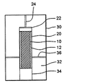
- FIG. 1 is a cross-sectional view schematically showing an example of an explosion device used in the production method of the present invention.
- FIG. 2 is a schematic diagram for explaining the mechanical compounding process.
- FIG. 3 is a drawing-substituting photograph of the carbon particles obtained in Experimental Example 3 (3 # 5).
- FIG. 4 is a transmission electron microscope (TEM) photograph of the carbon particles obtained in Experimental Example 3 (3 # 5).
- FIG. 5 is an X-ray diffraction chart of the carbon particles obtained in Experimental Example 3 (3 # 5).
- FIG. 6 is a calibration curve graph used when determining the diamond content ratio of carbon particles.
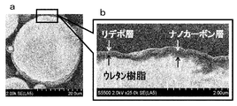
- FIG. 7a is a drawing substitute photograph in which the surface of urethane resin particles is photographed, and FIG.
- FIG. 7b is a drawing substitute photograph in which the surface of urethane resin particles coated with carbon particles is photographed.
- FIG. 8 is a drawing-substituting photograph in which a cross section of the coated particle is photographed.
- FIG. 9a is a drawing-substituting photograph in which the surface of the inert alumina particles is photographed, and
- FIG. 9b is a drawing-substituting photograph in which the surface of the inert alumina particles coated with the carbon particles is photographed.
- FIG. 10 is a drawing-substituting photograph in which a cross section of the coated particle is photographed.
- FIG. 11a is a drawing-substituting photograph in which the surface of aluminum particles is photographed, and FIG.
- FIG. 11b is a drawing-substituting photograph in which the surface of aluminum particles coated with carbon particles is photographed.
- FIG. 12 is a drawing-substituting photograph in which a cross section of the coated particle is photographed.
- FIG. 13 a is a drawing substitute photograph of a SUS304 type stainless steel plate used as a base material
- FIG. 13 b is a drawing substitute photograph of a functional material having coated particles supported on the surface of the base material. It is.
- FIG. 14a is a drawing-substituting photograph taken by observing a cross section of the functional material shown in FIG. 13b with an optical microscope
- FIG. 14b shows a portion surrounded by a square in the photograph a of FIG. It is an enlarged drawing substitute photograph.
- the present inventors have studied a method for efficiently producing carbon particles containing nanodiamond and nanographite by the detonation method, and carbon particles containing nanodiamond and nanographite by the detonation method using explosive-based materials.
- explosive reaction is performed by placing an explosive substance that is liquid at room temperature and normal pressure around an explosive material, carbon particles rich in nanodiamonds can be obtained compared to the conventional method described above.
- a patent application was filed as Japanese Patent Application No. 2014-113057. Thereafter, as a result of further investigation, it was found that the coated particles formed by coating the carbon particles obtained by the above production method on the surface of the substrate particles are useful as a new material, and the present invention has been completed. did.
- the carbon particles are manufactured by a detonation method, and the method for manufacturing the carbon particles is liquid at room temperature and normal pressure around a raw material containing an aromatic compound having three or more nitro groups. Placing explosive substances; And detonating the explosive substance.
- a detonation method a method for manufacturing the carbon particles is liquid at room temperature and normal pressure around a raw material containing an aromatic compound having three or more nitro groups.
- an explosive substance that is liquid at normal temperature and normal pressure is placed around a raw material containing an aromatic compound having three or more nitro groups.
- the aromatic compound having three or more nitro groups is an explosive raw material contained in a raw material which is a carbon source for the detonation method.
- an explosive substance that is liquid at normal temperature and pressure is a substance that causes stable detonation in order to generate carbon particles from a raw material.
- numerator which comprises an explosive substance contains a carbon atom
- the said explosive substance may become a carbon source with a raw material substance.
- the aromatic compound having three or more nitro groups is a compound having a structure in which three or more hydrogen atoms of an aromatic ring such as benzene, naphthalene, and anthracene are substituted with nitro groups.
- the aromatic compound may have a substituent other than a nitro group, and examples of the substituent include an alkyl group, a hydroxy group, a hydroxyalkyl group, an amino group, and a halogen group.
- positional isomer There may be a positional isomer depending on the positional relationship between the nitro group and the substituent. Any of the positional isomers can be used in the above production method. For example, if the aromatic compound is trinitrotoluene, six types of positional isomers can be considered depending on the positional relationship between three nitro groups and one methyl group. In this specification, unless otherwise specified, trinitrotoluene means 2,4,6-trinitrotoluene.
- aromatic compound examples include trinitrotoluene (also called TNT), trinitrophenylmethylnitramine (also called tetryl), and the like. Of these aromatic compounds, TNT is particularly preferable because it is easily available.
- TNT is particularly preferable because it is easily available.
- the above aromatic compounds may be used alone or in combination of two or more.
- the raw material containing the aromatic compound include mixed explosives mainly composed of RDX and TNT, such as composition B, cyclotol (75/25), (70/30), (65 / 30), composition B-2; mixed explosives mainly composed of HMX and TNT, such as octol (75/25); Moreover, as a specific example using 2 or more types of the said aromatic compound together, the mixed explosive which has TNT and tetril as a main component, for example, tetritol etc. are mentioned.
- the content ratio of the aromatic compound having three or more nitro groups in the raw material is usually 50% by mass or more, preferably 80% by mass or more, more preferably 90% by mass or more, based on the total mass of the raw material. More preferably, it is 95% by mass or more.
- the content of the aromatic compound having three or more nitro groups is most preferably 100% by mass, but the upper limit may be preferably about 99% by mass or 98% by mass.
- a liquid explosive having fluidity at normal temperature and normal pressure is used as the explosive substance.
- liquid explosives are used, the degree of freedom of shape is high and enlargement is easier than when solid explosives are used, and operability and safety can be improved.
- the liquid explosive may not contain carbon as a constituent element.
- liquid explosive examples include a mixture of hydrazine and hydrazine nitrate, a mixture of hydrazine and ammonium nitrate, a mixture of hydrazine, hydrazine nitrate and ammonium nitrate, nitromethane, and a mixture of hydrazine and nitromethane.
- hydrazine includes its hydrate, hydrazine hydrate.
- the amount of the raw material and the explosive material used may be appropriately adjusted according to the desired amount of carbon particles, and is not particularly limited.
- the ratio (explosive material / raw material) is a mass ratio, Preferably it is 0.1 or more, More preferably, it is 0.2 or more, Preferably it is 1 or less, More preferably, it is 0.9 or less, More preferably, it is 0.8 or less.
- the ratio is 1 or less, the amount of explosive substance used is appropriate, and the production cost of carbon particles can be reduced.
- the ratio by mass ratio at which carbon particles can be recovered from carbon in the raw material is referred to as “carbon particle yield” which is the mass ratio of the carbon particles to the raw material.
- carbon particle yield which is the mass ratio of the carbon particles to the raw material.
- nanodiamond yield which is the mass ratio of nanodiamond to the raw material.
- FIG. 1 is a cross-sectional view schematically showing an example of an explosion device used in the manufacturing method.
- the explosive device shown in FIG. 1 is merely illustrative and is not intended to limit the present invention.
- the explosive substance 12 is arranged around the raw material substance 10.
- the high temperature and high pressure accompanying the shock wave generated by the detonation of the explosive substance 12 is applied to the raw material 10 as uniformly as possible, that is, in an explosive shape. It is preferable to arrange the source material 10 and the explosive material 12 symmetrically so as to ensure symmetry.
- the raw material 10 is a solid and the explosive material 12 is a liquid explosive, for example, the raw material 10 is melted and pressed to produce a cylindrical molded body, and the molding is performed. After the body is placed in the center of the inside of the cylindrical container with the axial direction aligned, a liquid explosive may be injected around it.
- explosion container a container that stores the raw material 10 and the explosive substance 12 is referred to as an “explosion container”.
- the explosion container 20 it is preferable to use a container made of a synthetic resin such as an acrylic resin because impurities such as metals can be prevented from being mixed.
- the explosive substance 12 is then detonated to generate carbon particles from the raw material substance 10.
- a shock wave generated by the detonation reaction of the explosive substance 12 propagates toward the raw material 10, and the shock wave compresses the raw material 10 to cause detonation, which is decomposed and liberated from organic molecules constituting the raw material 10.
- Atoms change to carbon particles containing nanodiamond and nanographite.
- Detonation may be performed in either an open system or a closed system.
- the detonation in the open system may be performed, for example, inside the earth excavated underground or a tunnel.
- the detonation in the sealed system is preferably performed in a state where the raw material and the explosive material are loaded in a metal chamber, for example.
- the state of being loaded in a metal chamber means that, for example, a molded body of the raw material and the explosive material or an explosion container containing the raw material and the explosive material is suspended in the chamber. It is in the state. It is preferable to perform detonation in a sealed system because the residue can be prevented from scattering over a wide range.
- explosion chamber the chamber used for detonation.
- the explosion chamber may be made of metal or concrete as long as it has sufficient strength to withstand detonation.
- the atmosphere in the explosion chamber When detonation is performed in an explosion chamber, if the atmosphere in the explosion chamber does not substantially contain oxygen during detonation, the oxidation reaction of carbon can be suppressed. Can be improved.
- the atmosphere in the explosion chamber is replaced with an inert gas such as nitrogen gas, argon gas, carbon dioxide gas, or the inside of the explosion chamber is ⁇ 0.1 to ⁇ 0. .01 MPaG (symbol “G” after the pressure unit indicates a gauge pressure; the same applies hereinafter), or the inside of the explosion chamber is evacuated to release the atmosphere (oxygen).
- the inert gas as described above may be filled to a weak positive pressure of about +0.000 to +0.001 MPaG.
- the molded body or the explosion container 20 may be installed in the cooling container 30 and the coolant 32 may be filled in the gap between the cooling container 30 and the molded body or the explosion container 20.
- the coolant 32 is a substance that does not substantially generate an oxidizing substance such as oxygen or ozone, an oxidation reaction of carbon can be suppressed, so that the yield of carbon particles is improved.
- coolant 32 for example, oxygen gas dissolved in the coolant 32 is removed, or a coolant 32 that does not contain a constituent element that generates an oxidizing substance such as oxygen or ozone is used.
- the coolant 32 include water and alkyl halides (for example, chlorofluorocarbons, carbon tetrachloride), and water is particularly preferable because it has little adverse effect on the environment.
- the explosive substance 12 is normally detonated using a detonator or a detonation wire, but in order to cause detonation more reliably, an explosive agent 22 is placed between the explosive substance 12 and the detonator or detonator. It may be interposed. In this case, after the explosive 22 and the detonator or explosive wire 24 are attached to the molded body or the explosion container 20, for example, it is loaded into the explosion chamber.
- the explosive charge 22 for example, Composition C-4, SEP manufactured by Asahi Kasei Chemicals Corporation and the like can be used.
- the molded body and the explosion container 20 are stored in a liquid-tight container (for example, a bag made of an olefin-based synthetic resin such as polyethylene or polypropylene). It is preferable to prevent the coolant 32 from entering the container 20. After forming in this way, if the explosive substance 12 is detonated and detonated, carbon particles containing nanodiamond and nanographite are obtained as the residue.
- a liquid-tight container for example, a bag made of an olefin-based synthetic resin such as polyethylene or polypropylene.
- the residue obtained in the detonation process may contain debris of the container, blasting debris such as wires and wires as impurities.
- the carbon particles can be obtained in the form of a dry powder having a desired particle size.
- coarse rubble is removed from the residue obtained in the detonation process, and then classified by a sieve or the like, separated into a sieve passing part and a residue on the sieve, and the sieve passing part is recovered.
- the residue on the sieve may be classified again after crushing.
- Water is separated from the finally obtained sieve passage to obtain a dry powder.
- the sieve opening may be adjusted as appropriate, separation and purification treatments may be repeated, and the sieve passing through the sieve having an opening corresponding to the desired particle size may be used as the product. More specifically, for example, when detonation is performed in the explosion chamber using water as the coolant 32, the water containing the residue may be collected and settled and separated. After removing the coarse rubble, the supernatant liquid is recovered as a waste liquid, and the precipitate is classified with a sieve or the like to obtain a sieve passing part.
- the residue on the sieve may be crushed and separated by ultrasonic vibration or the like and classified again with a sieve or the like.
- the residue on the sieve having an opening of about 100 ⁇ m is often explosive debris such as debris of the explosion container 20, conductors, or wires, and is disposed of as industrial waste after collection.
- the residue on the sieve having an opening of about 32 ⁇ m may be crushed and separated by ultrasonic vibration or the like and classified again with a sieve or the like.
- the recovered product is separated from water by centrifugation or the like and dried to obtain a carbon particle powder having a desired particle size.
- acrylic resin particles or powder may be mixed in the residue obtained in the detonation process.
- the acrylic resin may be removed by elution treatment with acetone.
- the metal such as iron may be removed by treatment with hot concentrated nitric acid.
- the carbon particles obtained by the above production method contain nanodiamond and nanographite.
- the carbon particles can be defined by the content ratio of carbon components in mass ratio.
- the carbon particles are decomposed to the atomic level by causing detonation of the raw material, and the carbon atoms released without being oxidized are aggregated and generated in a solid state.
- the raw material is brought into a high temperature and high pressure state due to a decomposition reaction, but immediately expands and is cooled.
- the process from high temperature and high pressure to vacuum cooling occurs in a much shorter time than normal combustion or deflagration, which is an explosion phenomenon slower than detonation, so there is no time for the agglomerated carbon to grow greatly. Scale carbon particles are produced.
- the pressure at the time of detonation becomes very high, so it can be easily predicted from the thermodynamic equilibrium phase diagram of carbon.
- the produced carbon particles contain a large amount of nanodiamonds.
- the pressure at the time of detonation does not increase, so that nanodiamond synthesis is not achieved and nanoscale carbon particles other than nanodiamonds are obtained.
- This carbon particle contains a lot of nanographite. Therefore, the content ratio of nanodiamond and nanographite can be controlled by the pressure at the time of detonation of the raw material.
- X-ray diffraction can confirm nanodiamonds, but for nanoscale carbon particles, what substances are contained in addition to nanographite and fine multi-walled carbon nanotubes that give a peak around 26 °? It is not clear. Fine single-walled (single) carbon nanotubes and various fullerenes are not involved in the peak near 26 °, and thus the quantitative result based on the peak near 26 ° does not include the amount produced. Furthermore, it is expected that the peak near 26 ° also includes nanoscale carbon particles whose structure of the laminate (graphite) is changed to, for example, a turbulent structure by detonation. It cannot be denied that the mixed peak due to these deformed nanoscale carbon particles acts in the direction of widening the peak width around 26 °.
- nanodiamond and nanographite manufactured based on this manufacturing method have a mass ratio within a certain range. It is expected to fall within the ratio. For this reason, it is expected that carbon other than nanodiamonds will not cause a large error even when nanographite is used. That is, since it is presumed that there is little carbon having a structure other than nanodiamond and nanographite, the carbonaceous material other than nanodiamond may be nanographite, and the ratio of nanodiamond and nanographite may be obtained.
- the carbon particles include nanodiamond and nanographite, but the carbon particles used in the present invention preferably have a relatively high content of nanodiamonds.
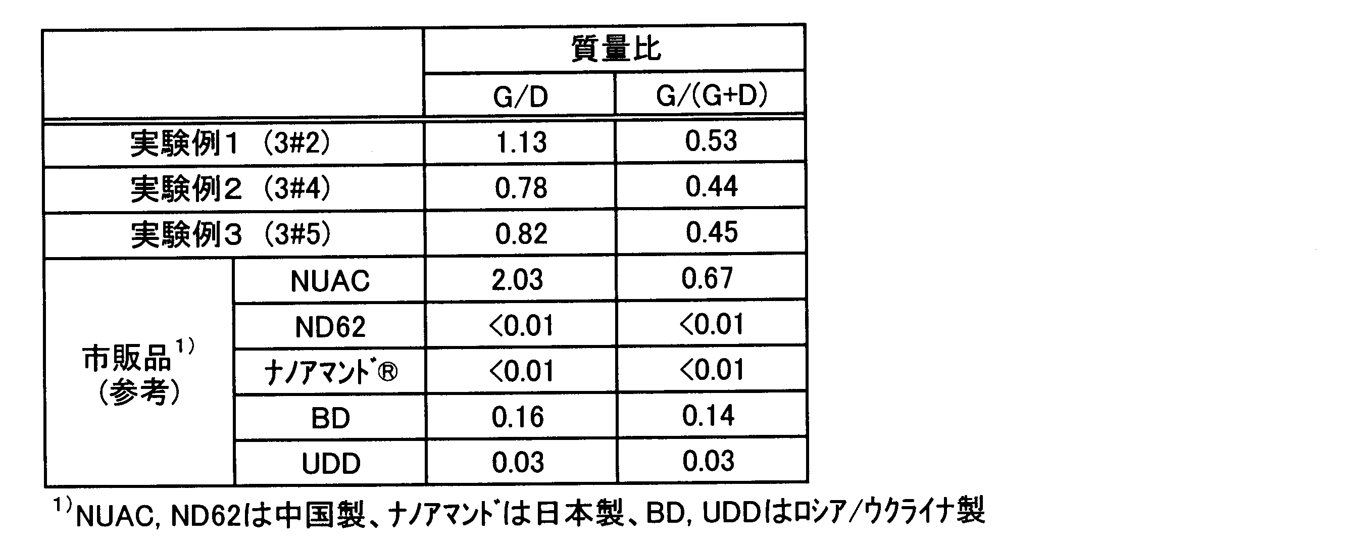
- the mass of nanographite is G and the mass of nanodiamond is D
- the lower limit of the mass ratio G / D is infinitely 0. That is, the mass ratio G / D is preferably more than zero.
- the upper limit of mass ratio G / D is not specifically limited, Preferably it is 10 or less, More preferably, it is 8 or less, More preferably, it is 6 or less.
- mass ratio G / D is calculated
- the coated particles of the present invention are characterized in that carbon particles obtained by the above production method are configured to be coated on the surface of base material particles. By covering the surface of the substrate particles with the carbon particles, it can be used for various applications as a new material.
- the carbon particles are preferably coated on the surface of the base particles so that the film thickness is 0.004 ⁇ m. That is, when the carbon particles are coated most thinly, it is recommended that the film thickness be 0.004 ⁇ m.
- the film thickness may be 1 ⁇ m or more. Although the upper limit of the said film thickness is not specifically limited, For example, it is 10 micrometers or less.
- the type of the base material particles is not particularly limited, and examples thereof include carbon, resin, glass, ceramics, metal, and natural materials.
- Examples of carbon include artificial graphite.
- Examples of the resin include acrylic, urethane, nylon, polyethylene, high molecular weight polyethylene, and polytetrafluoroethylene.
- Examples of the glass include various amorphous glasses and crystallized glasses.
- Examples of the ceramic include SiC, inert alumina, silica, titania, and zirconia.
- the metal include aluminum, pure copper, bronze, brass, carbon steel, stainless steel, maraging steel, and nickel-based alloy.
- natural materials such as synthetic zeolite, wood chips, minerals, coal, and rocks may be used.
- the size of the substrate particles is not particularly limited, and may be, for example, about 2 to 550 ⁇ m.
- the substrate particles are preferably covered with the carbon particles so that the surfaces thereof are completely covered.
- the present invention is not limited to this, and the carbon particles are formed only on a part of the surfaces of the substrate particles. It may be attached.
- the coated particles include a step of arranging an explosive substance that is liquid at normal temperature and pressure around a raw material containing an aromatic compound having three or more nitro groups, and a step of detonating the explosive substance.
- the obtained carbon particles can be manufactured by a method including a step of coating the surface of the substrate particles by a mechanical composite method.
- the mechanical compounding method means mixing or pulverization. That is, from the relationship between the function expression of particles in mechanical powder processing and the added energy, as the added energy increases, from the mere change of place (mixing) to uniform dispersion, refinement (pulverization), A high level of functionality is added, such as surface coating (compositing).
- solid-solid reactions and mechanochemical reactions occur when mechanical energy is high. That is, the interaction occurs at a scale corresponding to the applied energy level, and the interaction at the molecular / atomic level appears at a higher energy.
- composite particles have the following two forms. Coated composite particles in which the surface of the core particle is covered with fine particles (child particles), and the dispersed composite particle that forms a structure in which the child particles enter the core particles or the core particles and the child particles interlace with each other There is.
- Capsule-like composite particles have a core-shell type. What kind of composite particles are generated depends on the physical and chemical properties of the core particles / child particles, and also on the magnitude of the mechanical action and atmosphere of the composite.
- the mechanical compounding process includes (1) particle collision / adhesion, (2) particle disintegration / dispersion, (3) fine particle mixing, (4) particle fusion / It consists of embedding.
- the powerful impact, compression, and shearing action that acts on the particles between the rotor and balls that rotate at high speed and the container and inner piece facilitates these processes, enabling compounding and control of surface properties. .
- hybridization systems high-speed air impact method
- mechano-fusion systems etc.
- a hybridization system a very strong impact force is applied to particles due to a collision with a blade or a casing, so that foreign substances can be embedded or fused.
- the mechano-fusion system is also expected to be applied to mechanical alloying because of its powerful compressive and shearing forces.
- there is a case where such a strong mechanical action is contrary to the function expression of the composite particles. For example, there is a decrease in function or a change in crystal structure due to a sudden temperature rise or impact. A relatively mild technique has been developed for such cases.
- a stirring mixer such as a Henschel mixer that can disperse fine particles well by rotation of a stirring blade. Conveniently for precise fine mixing at the particle surface.
- a composer that can be expected to have an intermediate mechanical action that can be fixed firmly without changing the structure of the substance.
- the above-described Henschel mixer was improved, and an “MP5 mixer (composite)” apparatus manufactured by Nippon Coke Kogyo Co., Ltd. having a function similar to a hybridization system was used.
- the coated particles of the present invention can be obtained not only by this apparatus but also by the above-described various mechanical composite methods.
- the carbon particles may be fluorinated and then coated on the surface of the substrate particles.
- Fluorine treatment of carbon particles in advance allows the coated particles to have fluorine such as water repellency, oil repellency, mold release, non-adhesiveness, antifouling, chemical resistance, lubricity, antibacterial and oxidizing power. It can give its own functions. Further, the coated particles can be easily dispersed in both water and an organic solvent.
- fluorination treatment for example, a direct fluorination method in which the base particles react with fluorine gas or a fluorinating agent derived from fluorine gas can be employed. A method of fluorination by reacting fluorine plasma can also be employed. Further, a method of fluorinating in a solution with a fluorinating agent such as a fluoroalkyl group-containing oligomer can also be employed. Also, fluorination with a fluorinating agent in an ionic liquid can be employed.
- Graphite fluoride is drawing attention as a new industrial material because of its chemical and physical properties.
- Graphite fluoride is a white powdery inorganic sheet polymer produced by direct reaction of carbon and fluorine.
- Graphite fluoride tends to be collocated with fluorocarbons such as CF 4 , C 2 F 6 , and ⁇ CF 2 —CF 2 ⁇ n.
- fluorocarbons such as CF 4 , C 2 F 6 , and ⁇ CF 2 —CF 2 ⁇ n.
- graphite fluoride produced from graphite becomes crystalline, polycondensation, etc. There is a feature that it is a solid polymer that cannot be synthesized by this means. Therefore, it is called graphite fluoride to distinguish it from general carbon and fluorine compounds.
- These carbon materials form a system that is treated as a substance in the boundary region between organic chemistry and inorganic chemistry from the history of their production.
- graphite fluoride produced from various carbon raw materials such as amorphous carbon, carbon black, petroleum coke, and graphite can be expressed by (CF) n .
- the graphite fluoride in the present invention has the most C—F bonds as described later, but is characterized in that C—F 2 bonds and C—F 3 bonds are also observed.
- the anti-abrasives and lubricants are utilized by taking advantage of the excellent characteristics of nanodiamonds such as abrasiveness, durability, and wear resistance. It is useful for applications such as, and taking advantage of the excellent properties such as conductivity, water repellency and biocompatibility of nanographite, fiber materials, resin coatings that provide functionality, drug delivery systems, electronic device covers, It is useful for applications such as battery electrode materials, conductive films, reinforced rubber / water-repellent rubber, catalysts and adsorbents.
- the present invention also includes a functional material having the coated particles supported on the surface of the base material.
- the following effects can be enjoyed by carrying the coated particles. That is, depending on the type of the base material supporting the coated particles, the surface hardness of the base material is increased, the friction coefficient is decreased to improve the lubricity, the wear resistance is improved, the catalytic property (reactive activity) ), Improved conductivity, improved thermal conductivity, improved corrosion resistance, or fluorinated is water repellency, oil repellency, release property, non-adhesive property, Improves dirtiness, chemical resistance, lubricity, antibacterial power and oxidizing power.
- the type of the base material supporting the coated particles is not particularly limited, and examples thereof include carbon, wood, glass, resin, ceramics, metal, concrete, and outer wall material.
- Examples of the carbon include graphite, glassy carbon, artificial graphite, isotropic graphite, carbon black, fine carbon, C / C composite (Carbon Fiber Reinforced Carbon Composite), carbon fiber, and the like. Can be mentioned.
- the glass examples include amorphous glass such as Pyrex (registered trademark) glass and quartz glass, crystallized glass such as lithium aluminosilicate and magnesium aluminosilicate, and special glass such as conductive glass.
- amorphous glass such as Pyrex (registered trademark) glass and quartz glass
- crystallized glass such as lithium aluminosilicate and magnesium aluminosilicate
- special glass such as conductive glass.
- thermoplastic resins examples include thermoplastic resins, thermosetting resins, nylon, and engineering plastics.
- thermoplastic resin examples include polyethylene, polypropylene, polyvinyl chloride, polystyrene, polyvinyl acetate, polyurethane, polytetrafluoroethylene, ABS resin, acrylic resin, and polycarbonate.
- thermosetting resin a phenol resin, an epoxy resin, a polyester resin etc. are mentioned, for example.
- Examples of the engineering plastic include, for example, polyacetal, bakelite, epoxy glass, ultrahigh molecular weight polyethylene, polyamide, modified polyphenylene ether, polyethylene terephthalate, polybutylene terephthalate, polyphenylene sulfide, polyarylate, polyamide imide, polyether imide, polyether ketone, Examples include polyether ether ketone, polysulfone, polyether sulfone, and fluoropolymer.
- the ceramics include oxide ceramics such as alumina, silica and quartz, carbide ceramics such as silicon carbide, nitride ceramics such as silicon nitride and aluminum nitride, titania and zirconia.
- the metal examples include ordinary steel, tool steel, bearing steel, stainless steel, iron, cast iron, and other iron-based metals, copper, copper alloys, aluminum, aluminum alloys, nickel, nickel-base alloys, tin, lead, cobalt,
- Non-ferrous metals such as titanium, chromium, gold, silver, platinum, palladium, magnesium, manganese, and zinc can be used.
- these alloys may be sufficient and the oxide of these metals etc. may be sufficient.
- the shape of the base material is not particularly limited, and examples thereof include a plate shape, a columnar shape, and a cylindrical shape.
- the functional material can be produced by supporting the coated particles on the surface of a base material.
- Examples of the method for supporting the coated particles on the surface of the base material include (1) thermal spraying, (2) rolling, and (3) plating.
- (1) Thermal spraying and (2) rolling can be collectively referred to as a thermomechanical processing method.
- WPC Wave Peening Cleaning
- Thermal spraying is a surface modification technology that forms a film by spraying material particles obtained by melting or semi-melting a thermal spray material such as metal or ceramics onto the surface of a base material using a combustion flame or electrical energy. It is a kind. As the heat source for melting the thermal spray material such as powder and wire, combustion gas, plasma, etc. are used. The melted material becomes fine particles having a diameter of several ⁇ m to several hundreds of ⁇ m, and several tens of meters to several tens of seconds. A film is formed by laminating flat fine particles that collide with the surface of the base material at a high speed of 100 m / second and rapidly solidify (in the case of liquefied metal particles, 10 7 ° C / second or more).
- This laminated structure is a major feature of the thermal spray coating and is also called a lamellar structure.
- a thermal spray material By spraying a thermal spray material, it is used for the purpose of adding functions and qualities such as abrasion resistance, corrosion resistance, impermeableness, and conductivity separately from the material to the surface of various equipment and devices. There are many methods and processes for thermal spraying.
- the above-mentioned spraying method is not particularly limited, and examples thereof include flame spraying, arc spraying, plasma spraying, explosion spraying, high-speed flame spraying, and cold spray spraying.
- the flame spraying, arc spraying, and plasma spraying are known as temperature-oriented spraying methods in which they are sufficiently melted and sprayed at a low speed.
- the above-described explosion spraying, high-speed flame spraying, and cold spray spraying are known as speed-oriented spraying methods in which particles in a semi-molten state are sprayed at high speed.
- cold spray spraying is one of the surface coating techniques by high-speed fine particle collision, and is characterized by acceleration by a low-temperature high-speed working gas.
- the material particles do not melt because the gas temperature is lower than the melting point of the material particles. Therefore, in recent years, it is also used for thermal spraying of nanocarbon materials such as carbon nanotubes.
- the nano-sized carbon particles constituting a part of the coated particles are obtained by the detonation method and are exposed to a high temperature of at least 800 ° C. at the time of manufacture. Heat resistance is expected to be higher than nano-carbon materials. Therefore, if metal, ceramic, or the like, which is a heat-resistant material, is selected as the base particle, it can be handled by a temperature-oriented spraying method, and it is not necessary to be bound by a speed-oriented spraying method.
- the wear resistance, slidability, conductivity (when the base material is ceramic / resin), etc. can be improved by the carbon particles present in the sprayed coating. It is done. Furthermore, when the carbon particles in the sprayed coating are positioned as fillers serving as catalysts, carriers, and binders, further functions can be expected. That is, in the above-mentioned fluorination treatment, the carbon particles supported on the coated particles are made into fluorinated nanographite so that the coated particles have water repellency, oil repellency, releasability, non-tackiness, antifouling properties, chemical resistance, Functions such as lubricity, antibacterial power and oxidizing power can be provided.
- the surface of the base material sprayed in the same manner as the fluorinated coated particles can have the function of fluorinated nanographite. That is, by fluorinating the surface of the base material that has been sprayed, the surface of the base material is water- and oil-repellent, mold release, non-adhesive, antifouling, chemical resistance, lubricity, antibacterial power, oxidation power, etc. It can have the function of.
- the rolling method is not particularly limited, and examples thereof include a press rolling method such as a roll press method and a belt press method, a forging method such as a batch type flat hot press method, and a clad rolling method.
- the rolling is not limited to the method of forming with only the coated particles, but may be a method of supplying the coated particles and a binder mixed. If the combination of the material of the base material particles and the base material is selected, the coated particles can be supported on the surface of the base material without an adhesive. For example, if a metal or ceramic with a high melting point is selected as the base particle, a resin with a low melting point is selected as the base material, and hot pressing is performed at a heating temperature slightly higher than the temperature on the low melting point side, the coated particle Can be welded to the base material.
- grains of coating particle will fuse
- alumina, SiC, stainless steel, maraging steel, tool steel or the like having high hardness is selected as the base particle, and various resins having low hardness, aluminum, copper or the like are selected as the base material, low heating is possible.
- the coated particles can be supported on the surface of the base material even by rolling at a temperature.
- a mixed powder of boride powder and aluminum alloy powder is directly extruded in a combination of aluminum and boron powder, which is difficult to uniformly dissolve.
- the binder agent is not limited to aluminum and aluminum alloy powders, and thermosetting resins and reactive hot melt adhesives that are often used for the production of plywood (plywood) can be used. Therefore, by rolling the coated particles of the present invention by various methods, the wear resistance, slidability, conductivity (when the base material is ceramic or resin), etc., can be improved by the carbon particles present in the sprayed coating. it is conceivable that.
- coated particles those obtained by coating the surface of base particles with carbon particles subjected to fluorination treatment may be used, or carbon particles that have not been subjected to fluorination treatment may be used.
- the coated particles may be prepared, coated on the surface of the base material, and then fluorinated.
- a functional material carrying coated particles on the surface of the substrate material can be produced by immersing and plating the substrate material in a plating bath in which the coated particles are dispersed.
- the plating method is not particularly limited, and may be, for example, electroplating or electroless (chemical) plating.
- the type of plating can be a single metal (eg, copper, nickel, chromium, tin, zinc, silver, gold, etc.) or an alloy (eg, brass, bronze, solder, Zn—Ni alloy, Zn—Fe alloy, Ni—P, Ni-B, Ni-W, Ni-Fe, etc.), which is a composite plating method in which fine particles including the coated particles are co-deposited on the plating metal.
- the plating bath is not particularly limited as long as the coated particles are dispersed.
- a plating bath in which the coated particles are dispersed can be used.
- Ni plating bath Ni plating bath, Ni—P plating bath, Ni—B plating bath, Ni—W plating bath, Ni—Cu—P plating bath, Ni—S plating bath, Cr— W plating bath, Cr—Mo plating bath, Cr—Fe plating bath, Cr—C plating bath, Cr—H plating bath, Fe—W plating bath, Fe—Mo plating bath, Fe—Ni plating bath, Co—W series Plating bath, nickel sulfamate plating bath, copper cyanide plating bath, copper pyrophosphate plating bath, copper sulfate plating bath, hexavalent chromium plating bath, zinc cyanide plating bath, zinc cyanide plating bath, alkaline tin plating bath, acidic A tin plating bath, a silver plating bath, a gold cyanide plating bath, an acidic gold plating bath, or the like can be used.
- Ni plating bath for example, Ni plating bath, for example, Ni plat
- the temperature of the plating bath at the time of plating is not particularly limited, and may be, for example, 50 to 90 ° C. Further, the plating solution may be stirred during plating.
- Coated particles were produced by coating the surface of the base particles with carbon particles produced according to the procedures described in Experimental Examples 1 to 3 below.
- the molded body as a raw material 10 was placed in the center of an explosion container 20 having an inner diameter of 12 cm and a height of 20 cm, and the liquid explosive was filled as an explosive substance 12 around the center.
- An explosive 22 (SEP), explosive wire, and No. 6 electric detonator 24 were attached to the top of the explosion container 20, covered, and stored in a liquid-tight polyethylene bag.
- a container having a capacity of 200 L was used as the cooling container 30.
- the explosion container 20 was installed in the cooling container 30. At this time, the outer bottom surface of the explosion container 20 was adjusted to be 29.5 cm in height from the inner bottom surface of the cooling container 30 using the iron mount 34 and the iron holed disc 36.
- distilled water was put into the cooling container 30 as the cooling material 32, and the cooling material 32 was filled in the gap between the cooling container 30 and the explosion container 20.
- a polyethylene bag containing distilled water was placed on top of the cooling vessel 30.
- a total of 200 L of distilled water was used.
- the explosion chamber was evacuated from atmospheric pressure, and the amount of oxygen gas remaining in the explosion chamber was calculated to be about 25.5 g.
- the explosive material 12 was detonated by detonating the explosive line with the detonator. Then, about 200 L of water containing the residue was recovered from the explosion chamber and settled and separated to remove coarse rubble. At this time, since the supernatant liquid was strongly alkaline, the pH was adjusted to weak acidity by adding citric acid. The supernatant liquid that became weakly acidic was recovered as a waste liquid as it was. The precipitate was classified using a vibrating sieve device (“KG-700-2W” manufactured by KOWA) with a sieve having an opening of 100 ⁇ m and an opening of 32 ⁇ m. The portion passing through the 32 ⁇ m sieve was recovered as it was.
- KG-700-2W manufactured by KOWA
- the portion of the sieve having a mesh opening of 100 ⁇ m and the residue on the sieve having a mesh opening of 16 ⁇ m is crushed by an ultrasonic vibration device (“4G-250-3-TSA” manufactured by Crest) for about 5 minutes, and carbon from the rubble surface.
- an ultrasonic vibration device (“4G-250-3-TSA” manufactured by Crest) for about 5 minutes, and carbon from the rubble surface.
- a vibrating sieve device (“KG-700-2W” manufactured by KOWA)
- classification was performed again with a sieve having an opening of 100 ⁇ m, an opening of 32 ⁇ m, and an opening of 16 ⁇ m, and the portion passing through each sieve was collected. .
- Each sieve passage was left in an 80 ° C. drier (“OF-450S” manufactured by ASONE) for 24 hours to evaporate the moisture, and then dried powder.
- Table 1 shows the experimental contents, the total recovery amount and yield of carbon particles, and the total recovery amount and yield of diamond determined by the following XRD quantitative method.
- Table 1 shows the experimental contents, the total recovery amount and yield of carbon particles, and the total recovery amount and yield of diamond determined by the following XRD quantitative method.
- ⁇ TEM observation> Carbon particles obtained using a CCD camera capable of observing a lattice image of diamond and a graphitic carbon having a laminated structure and a TEM having a photographing magnification were observed.
- the specific measurement conditions of TEM are as follows.
- FIG. 3 is a drawing-substituting photograph of the carbon particles obtained in Experimental Example 3 (3 # 5). The photographic magnification corresponds to 320,000 times when FIG. 3 is printed with the A4 horizontal plate. In FIG. 3, the portion indicated by the symbol D indicates nanodiamond.
- FIG. 4 shows a transmission electron microscope (TEM) photograph of the carbon particles obtained in Experimental Example 3 (3 # 5) passing through a 16 ⁇ m sieve.
- TEM transmission electron microscope
- the photograph a is an enlarged photograph of a part of the carbon particles having a large number of round shapes, and the photograph magnification corresponds to 5.9 million times. From this photograph a, it can be confirmed that the round-shaped carbon particles have a particle size of about 4.1 nm.
- Photo b like photo a, is a magnified image of the carbon particles found out of round shape, and corresponds to a photo magnification of 5.9 million. From this photograph b, it can be confirmed that the round-shaped carbon particles have a particle size of about 9.5 nm. As described above, the round-shaped carbon particles observed in the photographs a and b are considered to be nanodiamonds.
- X-ray diffraction (XRD) of the obtained carbon particles was measured and evaluated.
- the integrated intensity was determined for the diffraction peak, and the proportion of nanodiamond contained in the carbon particles was determined using each calibration curve prepared in advance.
- nanodiamonds purified by removing nanographite and the like from carbon particles containing nanodiamonds separately produced in the present invention with perchloric acid were used.
- the calibration curve for nano-diamonds is the ratio of the integrated intensity of the above diffraction peaks to the integrated intensity of the diffraction peaks at the Si 220 face and Si 311 face of the silicon crystal added to each sample using five standard samples. From this, 4 inspections were made. The reason why the two peaks of the silicon crystal are used is to suppress the influence of the orientation of the powder silicon.
- the five standard samples are obtained by mixing silicon crystals so that the nanodiamond is 0% by mass, 25% by mass, 50% by mass, 75% by mass, and 100% by mass.
- the area intensity ratio of the diffraction peaks was calculated from the measurement result of X-ray diffraction (XRD), and the content ratio of nanodiamonds in the carbon particles was determined using the calibration curve shown in FIG.
- the total recovered amount of nanodiamonds was calculated by multiplying the content of the obtained nanodiamonds by the total recovered amount of carbon particles. It was found that the carbon particles obtained by the above production method are composed mainly of nanodiamond and nanographite. Carbon components having other structures were not substantially recognized.
- the content ratio of nanodiamonds in the carbon particles obtained in the above experimental examples 1 to 3 (D: where carbon particles are 100% by mass) is obtained, and the carbon particles other than nanodiamonds are estimated as nanographite,
- the graphite content (G) was calculated.
- the mass ratio G / D was calculated based on the content ratio (D) of nanodiamond contained in the carbon particles and the content ratio (G) of nanographite contained in the carbon particles.
- Experimental Examples 1 to 3 are also shown in Table 1 below.
- the base particles include (a) urethane resin particles, (b) acrylic resin particles, (c) high molecular weight polyethylene resin particles, (d) PTFE particles, (e) SiC particles, (f) inert alumina particles, (G) SUS316L type stainless steel particles, (h) copper particles, (i) brass particles, (j) aluminum particles, (k) maraging steel particles Specific examples are as follows.
- SiC particles As the SiC particles, “SSC-A15” (average particle diameter ⁇ 18.6 ⁇ m, specific gravity 1.91 g / cm 3 ) manufactured by Shinano Electric Smelting Co., Ltd. was used.
- F As the above-mentioned inert alumina particles, “VERSALG series VGL-25” (average particle diameter of about 15 ⁇ m, specific gravity 1.93 g / cm 3 ) manufactured by Union Showa Co., Ltd., “DAW” manufactured by Denki Kagaku Kogyo Co., Ltd.
- the alloy name is PSS316L, and the particle size is below the sieve with an opening of 45 ⁇ m and above the sieve with an opening of 10 ⁇ m ( ⁇ 45 / + 10 ⁇ m).
- H As the copper particles, atomized spherical copper powder “Cu-At-200” manufactured by Fukuda Metal Foil Industry Co., Ltd. was used. Although the average particle diameter is unknown, the particle diameter of 45 ⁇ m or less is 55.7%. The apparent density is 4.66 g / cm 3 .
- As the brass particles atomized spherical bronze powder “BRO-At-200” manufactured by Fukuda Metal Foil Powder Industry Co., Ltd. was used.
- the average particle diameter is unknown, the particle diameter of 45 ⁇ m or less is 82.7%.
- the apparent density is 4.96 g / cm 3 and the amount of tin (Sn) in the component is 9.63%.
- J As the aluminum particles, atomized aluminum powder “350F” manufactured by Minalco Co., Ltd. was used.
- the average particle size is ⁇ 14.47 ⁇ m.
- K As the maraging steel particles, those manufactured by Sandvik Corporation were used.
- the alloy name is 18Ni300.
- the particle diameter is 99.5% at ⁇ 38 ⁇ m or less, and the average particle diameter is ⁇ 32.4 ⁇ m.
- the carbon particles obtained in Experimental Example 2 (3 # 4) and Experimental Example 3 (3 # 5) and the base material particles are put in “MP5 type composite” manufactured by Nippon Coke Industries, Ltd., and the blade rotation speed is set. Coated particles were produced by mechanically combining at 10,000 rpm and stirring time of 10 to 30 minutes.
- the MP5 type composite had a tank capacity of 6.5 L, a processing capacity of about 3 L, and a motor of 2.2 kW. Specific mixing ratios of the carbon particles and the base particles are as follows.
- the quantity of the said carbon particle is a value when base material particle
- the estimated film thickness is 13 nm.
- the estimated film thickness is 112 nm.
- the estimated film thickness is 7 nm.
- the estimated film thickness is 10 nm.
- (D) The PTFE particles were 200 g, and the carbon particles obtained in Experimental Example 3 (3 # 5) were 5% by mass.
- the estimated film thickness is 2 nm.
- E 500 g of SiC particles “SSC-A15” and 2% by mass of carbon particles obtained in Experimental Example 3 (3 # 5).
- the estimated film thickness is 39 nm.
- F-1 500 g of inert alumina particles “VERSAL-G series / VGL-25” and 5% by mass of carbon particles obtained in Experimental Example 3 (3 # 5). Although “VERSAL-G series / VGL-25” does not show the particle size distribution, it cannot be accurately determined. However, when the average particle size (d50) is assumed to be 15 ⁇ m, the estimated film thickness is 80 nm.
- (F-2) 250 g of the inert alumina particles “DAW-03” and 5% of the carbon particles obtained in Experimental Example 3 (3 # 5) were used.
- the estimated film thickness is 21 nm.
- (F-3) 100 g of inert alumina particles “ASFP-20” and the mass of carbon particles obtained in Experimental Example 3 (3 # 5) were 5%.
- the estimated film thickness is 2 nm.
- (F-4) 100 g of the inert alumina particles “AS-10” and the mass of the carbon particles obtained in Experimental Example 3 (3 # 5) were 5%.
- the estimated film thickness is 207 nm.
- the estimated film thickness is 174 nm.
- H 500 g of copper particles and 0.5% by mass of carbon particles obtained in Experimental Example 3 (3 # 5).
- the estimated film thickness is 67 nm.
- II 500 g of brass particles and 0.5% by mass of the carbon particles obtained in Experimental Example 3 (3 # 5).
- the estimated film thickness is 29 nm.
- J 250 g of aluminum particles and 5% by mass of carbon particles obtained in Experimental Example 3 (3 # 5).
- the estimated film thickness is 123 nm.
- K 500 g of maraging steel particles and 0.5% by mass of carbon particles obtained in Experimental Example 3 (3 # 5) were used.
- the estimated film thickness is 72 nm.
- FE-SEM field emission scanning electron microscope
- a part of the surface layer of the coated particles was cut out with a FIB apparatus and observed.
- IM-4000 ion milling processing apparatus
- the ion source was argon
- the acceleration voltage was 4.0 kV
- the processing temperature was ⁇ 10 ° C.
- S-5500 Field Emission Scanning Electron Microscope; FESEM
- FESEM Field Emission Scanning Electron Microscope
- LABSE reflected electron image
- FIG. 7a is a drawing-substituting photograph in which urethane resin particles before being coated with carbon particles are photographed.
- a drawing substitute photo b shown in FIG. 8 is an enlarged photograph of a portion surrounded by a square in the drawing substitute photo a shown in FIG.
- FIG. 9 b is a drawing-substituting photograph in which the inert alumina particles before being coated with the carbon particles are photographed.
- FIG. 10a shows a drawing-substituting photograph obtained by cutting the coated particles obtained in the above (f-1) with a CP apparatus and observing a cross section of the coated particles with an FE-SEM.
- a drawing substitute photograph b shown in FIG. 10 is an enlarged photograph of the portion (1) in the portion enclosed by a square in the drawing substitute photograph a shown in FIG.
- FIG. 11 a is a drawing-substituting photograph in which aluminum particles before being coated with carbon particles are photographed.
- FIG. 12 a shows a drawing-substituting photograph obtained by cutting the coated particles obtained in the above (j) with a CP apparatus and observing a cross section of the coated particles with FEEM.
- a drawing substitute photograph b shown in FIG. 12 is an enlarged photograph of a portion surrounded by a square in the drawing substitute photograph a shown in FIG.
- the surface of the base particle is coated with carbon particles.
- the observed coating film thickness was about 30 nm at the minimum and about 400 nm at the maximum. It can be seen that the average is 40 to 100 nm, which is almost equal to the estimated film thickness of 70 nm.
- the redeposited layer means that the waste generated when cutting with an ion beam to obtain a cross section is redeposited on the surface of the sample.
- a functional material was manufactured by supporting the coated particles obtained by coating the carbon particles obtained in Experimental Example 3 (3 # 5) on the surface of the base material by spraying on the surface of the base material. .
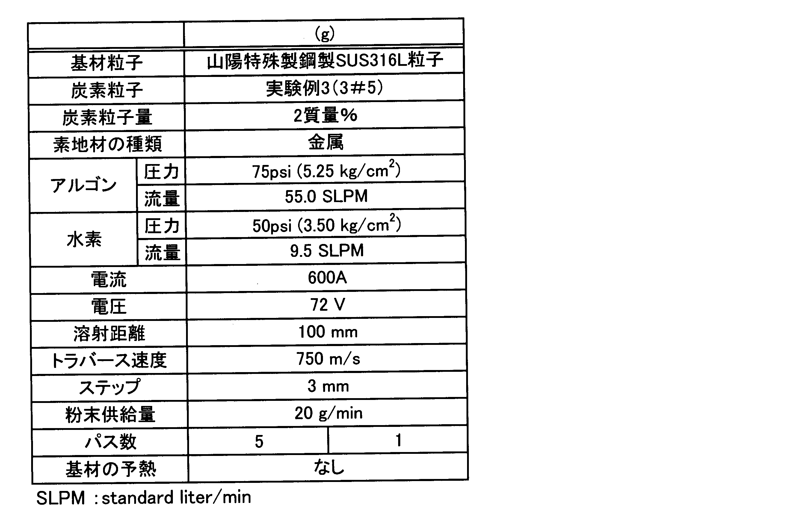
- the coated particles obtained in (g) above were used as the coated particles. That is, (g) is a coated particle obtained by coating SUS316L type stainless steel particles with the carbon particles obtained in Experimental Example 3 (3 # 5).
- the coated particles were supported on the surface of the base material by plasma spraying.
- As the base material SUS304 type stainless steel plate, carbon steel plate, copper plate, bronze plate, aluminum plate were used.
- plasma spraying an F4 type plasma spraying apparatus manufactured by Sulzer Metco Japan Co., Ltd. was used. The measurement conditions for plasma spraying are shown in Table 3 below.
- FIG. 13 shows a photograph substituted for a drawing of the SUS304 type stainless steel plate used as the base material and the obtained functional material.
- the thermal spray material coated particles obtained by mechanically compositing 2% by mass of carbon particles of Experimental Example 3 (3 # 5) with base particles of SUS316 type stainless steel particles were used.
- FIG. 13a is a drawing-substituting photograph in which the base material before plasma spraying of the coated particles is photographed
- FIG. 13b is a functional material after plasma coating of the coated particles obtained in (g) above on the base material. It is the drawing substitute photograph which image
- the film thickness of this functional material was calculated from the amount of increase in mass, it was predicted that a thermal spray coating of about 48 ⁇ m on average was formed by the coated particles.
- FIG. 14a shows a drawing-substituting photograph obtained by cutting the functional material shown in FIG. 13b with a precision cutter and observing the cross section with an optical microscope.
- FIG. 14 b shows a drawing substitute photograph taken by observing with the FE-SEM in order to further enlarge the portion surrounded by the square in the cross section.
- reference numeral 1 denotes a sprayed coating formed of coated particles
- 2 denotes a SUS304 type stainless steel plate as a base material.
- the coating particles can be supported on the base material by plasma spraying. Further, the thickness of the sprayed coating with the coated particles observed in FIG. 14 was about 20 ⁇ m at the minimum and about 60 ⁇ m at the maximum. It can be seen that the average is 40 to 50 ⁇ m, which is almost equal to the estimated film thickness of 48 ⁇ m.
- a functional material was manufactured by supporting the coated particles obtained by coating the carbon particles obtained in Experimental Example 3 (3 # 5) on the surface of the substrate particles on the surface of the base material by plating.
- the base particles alumina powder having a diameter of 4.3 ⁇ m was used.
- An aluminum alloy (A5052) plate was used as the base material.
- the carbon particles obtained in Experimental Example 3 (3 # 5) and the base material particles are put in “MP5 type composite” manufactured by Nippon Coke Industries, Ltd., the blade rotation speed is 10,000 rpm, and the stirring time is 10 to 30 minutes. As a result, it was mechanically combined to produce coated particles.
- the MP5 type composite had a tank capacity of 6.5 L, a processing capacity of about 3 L, and a motor of 2.2 kW. Specific mixing ratios of the carbon particles and the base particles are as follows.
- the plating was electroless (chemical) plating, a plating bath dispersed in a Ni—P bath so that the concentration of the coated particles was 2 g / L, and the plating bath temperature was 80 ° C. During plating, the plating solution was stirred. The plating time was 60 minutes.
- the thickness of the plating layer in the sample after plating was measured, and the results are shown in Table 4 below.
- the coverage of the base material surface by a plating layer was 100%.
- a plated layer was formed on the surface of the base material under the same conditions except that a Ni—P bath in which the above-mentioned coated particles were not dispersed was used.
- the thickness of the plated layer in the sample after plating was measured, and the results are shown in Table 4 below.
- the coverage of the base material surface by a plating layer was 100%.
- coated particles of the present invention are those in which the surface of a substrate is coated with carbon particles having a higher proportion of nanodiamonds than in the past, and can be expected as a novel material.
Landscapes
- Chemical & Material Sciences (AREA)
- Organic Chemistry (AREA)
- Engineering & Computer Science (AREA)
- Life Sciences & Earth Sciences (AREA)
- Inorganic Chemistry (AREA)
- Geology (AREA)
- General Life Sciences & Earth Sciences (AREA)
- Chemical Kinetics & Catalysis (AREA)
- Materials Engineering (AREA)
- Metallurgy (AREA)
- Mechanical Engineering (AREA)
- Physics & Mathematics (AREA)
- Plasma & Fusion (AREA)
- General Chemical & Material Sciences (AREA)
- Environmental & Geological Engineering (AREA)
- Carbon And Carbon Compounds (AREA)
- Chemically Coating (AREA)
- Coating By Spraying Or Casting (AREA)
Abstract
Description
上記炭素粒子は、爆轟法によって製造されたものであり、該炭素粒子の製造方法は、3個以上のニトロ基を有する芳香族化合物を含む原料物質の周囲に常温、常圧で液体である爆発性物質を配置する工程と、
前記爆発性物質を爆轟させる工程とを含むことを特徴とする。以下、工程順に説明する。
上記素地材に、上記被覆粒子を溶射することによって、表面に被覆粒子を担持した機能材料を製造できる。
上記素地材に、上記被覆粒子を圧延することによって、表面に被覆粒子を担持した機能材料を製造できる。
上記被覆粒子を分散させたメッキ浴に、上記素地材を浸漬してメッキすることによって、素地材の表面に被覆粒子を担持した機能材料を製造できる。
本実験例では、原料物質としてTNTを用いて、かつ、爆発性物質としてヒドラジン系液体爆薬を用いて、爆轟法により炭素粒子を製造した。具体的には、TNTは、市販されている円柱状の成型体(中国化薬製TNTの円柱形溶填物、直径10cm×長さ20cm)を用いた。TNT成型体の質量は2.52kg、密度は1.60g/cm3であった。また、硝酸ヒドラジンと抱水ヒドラジンを質量比3:1で混合して、0.93kgのヒドラジン系液体爆薬を調製した。
本実験例では、上記実験例1に対して、原料物質として、質量2.52kg、密度1.60g/cm3のTNT成型体の代わりに、質量3.82kg、密度1.61g/cm3のTNT成型体(中国化薬製TNTの円柱形溶填物、直径10cm×長さ30cm)を用いたこと、爆発性物質であるヒドラジン系液体爆薬の使用量を0.93kgから1.29kgに変更したこと以外は、上記実験例1と同じ条件で炭素粒子を製造した。
本実験例では、上記実験例1に対して、原料物質として、質量2.52kg、密度1.60g/cm3のTNT成型体の代わりに、質量6.30kg、密度1.59g/cm3のTNT成型体(中国化薬製TNTの円柱形溶填物、直径10cm×長さ50cm)を用いたこと、爆発性物質であるヒドラジン系液体爆薬の使用量を0.93kgから2.17kgに変更したこと、冷却材である蒸留水の使用量を200Lから220Lに変更したこと以外は、実験例1と同じ条件で炭素粒子を製造した。
ダイヤモンドと積層構造をもったグラファイト質の炭素の格子像が観察できるCCDカメラと撮影倍率を有するTEMを用いて得られた炭素粒子を観察した。TEMの具体的な測定条件は次の通りである。
・TEMの装置名:日本電子製透過型電子顕微鏡JEM-ARM200F
・測定方法:懸濁法、分散溶媒:メタノール
・加速電圧:200kV
・CCDカメラ:Gatan製UltraScan
・撮影倍率:30万倍、80万倍
・写真倍率:220万倍、A4サイズに印刷時は590万倍
実験例3(3#5)で得られた炭素粒子のうち、100μm篩通過分のXRDを測定し、チャートを図5に示す。X線回折の測定条件を以下に示す。
・X線回折装置の装置名:リガク製水平型X線回折装置SmartLab
・測定方法:θ-2θ
・X線源:Cu-Kα線
・励起電圧-電流:45kV-200mA
・発散スリット:2/3°
・散乱スリット:2/3°
・受光スリット:0.6mm

(b)上記アクリル樹脂粒子としては、根上工業株式会社製の「SE-010T」(平均粒径φ22μm、比重1.21g/cm3)、または東洋紡株式会社製の「タフチックAR650M」(平均粒径φ30μm、比重1.35g/cm3)、または根上工業株式会社製の「J-4PY」(平均粒径φ2.2μm、比重1.21g/cm3)を用いた。
(c)上記高分子量ポリエチレン樹脂粒子としては、三井化学株式会社製の「ミペロンPM-200」(平均粒径φ10μm、比重0.94g/cm3)を用いた。
(d)上記PTFE粒子としては、名古屋合成株式会社製の「分散液用潤滑粉」(平均粒径φ0.3μm、比重は不明)を用いた。
(e)上記SiC粒子としては、信濃電気製錬株式会社製の「SSC-A15」(平均粒径φ18.6μm、比重1.91g/cm3)を用いた。
(f)上記不活性アルミナ粒子としては、ユニオン昭和株式会社製の「VERSALGシリーズ・VGL-25」(平均粒径約φ15μm、比重1.93g/cm3)、電気化学工業株式会社製の「DAW-03」(平均粒径約φ4.3μm、比表面積0.5m2g)、電気化学工業株式会社製の「ASFP-20」(平均粒径約φ0.27μm、比表面積12.5m2/g)、または昭和電工株式会社製の「AS-10」(平均粒径φ約39μm、嵩密度1.8~2.4g/cm3)を用いた。
(g)上記SUS316L型ステンレス鋼粒子としては、山陽特殊製鋼株式会社製の噴霧(アトマイズ)粉末を用いた。合金名はPSS316Lで、粒度は目開きが45μmの篩下で且つ目開きが10μmの篩上(-45/+10μm)である。
(h)上記銅粒子としては、福田金属箔粉工業株式会社製のアトマイズ球状銅粉末「Cu-At-200」を用いた。平均粒径は不明であるが、粒径φ45μm以下が55.7%である。見掛け密度は4.66g/cm3である。
(i)上記黄銅粒子としては、福田金属箔粉工業株式会社製のアトマイズ球状ブロンズ粉末「BRO-At-200」を用いた。平均粒径は不明であるが、粒径φ45μm以下が82.7%である。見掛け密度は4.96g/cm3、成分中の錫(Sn)量は9.63%である。
(j)上記アルミニウム粒子としては、ミナルコ株式会社製のアトマイズアルミニウム粉末「350F」を用いた。平均粒径はφ14.47μmである。
(k)上記マルエージング鋼粒子としては、サンドビック株式会社製ものを用いた。合金名は18Ni300である。粒径はφ38μm以下が99.5%であり、平均粒径はφ32.4μmである。
(b-1)アクリル樹脂粒子「SE-010T」を500g、実験例2(3#4)で得られた炭素粒子を2質量%とした。試算膜厚は13nmである。
(b-2)アクリル樹脂粒子「タフチックAR650M」を500g、実験例2(3#4)で得られた炭素粒子を5質量%とした。試算膜厚は112nmである。
(b-3)アクリル樹脂粒子「J-4PY」を230g、実験例3(3#5)で得られた炭素粒子を5質量%とした。試算膜厚は7nmである。
(c)高分子量ポリエチレン樹脂粒子「ミペロンPM-200」を250g、実験例3(3#5)で得られた炭素粒子を2質量%とした。試算膜厚は10nmである。
(d)上記PTFE粒子を200g、実験例3(3#5)で得られた炭素粒子を5質量%とした。試算膜厚は2nmである。
(e)SiC粒子「SSC-A15」を500g、実験例3(3#5)で得られた炭素粒子を2質量%とした。試算膜厚は39nmである。
(f-1)不活性アルミナ粒子「VERSAL-Gシリーズ・VGL-25」を500g、実験例3(3#5)で得られた炭素粒子を5質量%とした。「VERSAL-Gシリーズ・VGL-25」は粒径分布が示されていないため正確に判らないが、平均粒径(d50)を15μmと仮定した場合の試算膜厚は80nmである。
(f-2)不活性アルミナ粒子「DAW-03」を250g、実験例3(3#5)で得られた炭素粒子を質量5%とした。試算膜厚は21nmである。
(f-3)不活性アルミナ粒子「ASFP-20」を100g、実験例3(3#5)で得られた炭素粒子を質量5%とした。試算膜厚は2nmである。
(f-4)不活性アルミナ粒子「AS-10」を100g、実験例3(3#5)で得られた炭素粒子を質量5%とした。試算膜厚は207nmである。
(g)SUS316L型ステンレス鋼粒子を500g、実験例3(3#5)で得られた炭素粒子を2質量%とした。試算膜厚は174nmである。
(h)銅粒子を500g、実験例3(3#5)で得られた炭素粒子を0.5質量%とした。試算膜厚は67nmである。
(i)黄銅粒子を500g、実験例3(3#5)で得られた炭素粒子を0.5質量%とした。試算膜厚は29nmである。
(j)アルミニウム粒子を250g、実験例3(3#5)で得られた炭素粒子を5質量%とした。試算膜厚は123nmである。
(k)マルエージング鋼粒子を500g、実験例3(3#5)で得られた炭素粒子を0.5質量%とした。試算膜厚は72nmである。

本出願は、2015年12月1日出願の日本特許出願(特願2015-235235)に基づくものであり、その内容はここに参照として取り込まれる。
12 爆発性物質
20 爆発容器
22 伝爆薬
24 雷管や導爆線
30 冷却容器
32 冷却材
34 架台
36 穴あき円板
Claims (9)
- 3個以上のニトロ基を有する芳香族化合物を含む原料物質の周囲に常温、常圧で液体である爆発性物質を配置する工程と、
前記爆発性物質を爆轟させる工程
により製造される炭素粒子が、基材粒子の表面に被覆されて構成されることを特徴とする被覆粒子。 - 前記炭素粒子は、フッ化処理したものである請求項1に記載の被覆粒子。
- 請求項1または2に記載の被覆粒子を素地材の表面に担持したことを特徴とする機能材料。
- 3個以上のニトロ基を有する芳香族化合物を含む原料物質の周囲に常温、常圧で液体である爆発性物質を配置する工程と、
前記爆発性物質を爆轟させる工程と、
得られた炭素粒子を、機械的複合化法によって基材粒子の表面に被覆する工程と
を含むことを特徴とする被覆粒子の製造方法。 - 前記炭素粒子を、フッ化処理した後、機械的複合化法によって基材粒子の表面に被覆する請求項4に記載の被覆粒子の製造方法。
- 請求項4または5に記載の製造方法で得られた被覆粒子を、素地材の表面に担持することを特徴とする機能材料の製造方法。
- 請求項4または5に記載の製造方法で得られた被覆粒子を、素地材の表面に担持した後、フッ化処理することを特徴とする機能材料の製造方法。
- 前記被覆粒子を、溶射、圧延、またはメッキにより前記素地材の表面に担持する請求項6に記載の機能材料の製造方法。
- 前記被覆粒子を、溶射、圧延、またはメッキにより前記素地材の表面に担持する請求項7に記載の機能材料の製造方法。
Priority Applications (4)
| Application Number | Priority Date | Filing Date | Title |
|---|---|---|---|
| EP16870725.5A EP3385222A4 (en) | 2015-12-01 | 2016-11-30 | COATED PARTICLE |
| US15/780,125 US20180363120A1 (en) | 2015-12-01 | 2016-11-30 | Coated particle |
| RU2018120080A RU2697123C1 (ru) | 2015-12-01 | 2016-11-30 | Покрытая частица |
| KR1020187015457A KR20180080267A (ko) | 2015-12-01 | 2016-11-30 | 피복 입자 |
Applications Claiming Priority (2)
| Application Number | Priority Date | Filing Date | Title |
|---|---|---|---|
| JP2015235235A JP6420228B2 (ja) | 2015-12-01 | 2015-12-01 | 被覆粒子の製造方法、並びに機能材料の製造方法 |
| JP2015-235235 | 2015-12-01 |
Publications (1)
| Publication Number | Publication Date |
|---|---|
| WO2017094788A1 true WO2017094788A1 (ja) | 2017-06-08 |
Family
ID=58797352
Family Applications (1)
| Application Number | Title | Priority Date | Filing Date |
|---|---|---|---|
| PCT/JP2016/085595 Ceased WO2017094788A1 (ja) | 2015-12-01 | 2016-11-30 | 被覆粒子 |
Country Status (6)
| Country | Link |
|---|---|
| US (1) | US20180363120A1 (ja) |
| EP (1) | EP3385222A4 (ja) |
| JP (1) | JP6420228B2 (ja) |
| KR (1) | KR20180080267A (ja) |
| RU (1) | RU2697123C1 (ja) |
| WO (1) | WO2017094788A1 (ja) |
Families Citing this family (4)
| Publication number | Priority date | Publication date | Assignee | Title |
|---|---|---|---|---|
| EP3785903B1 (en) * | 2018-04-23 | 2025-05-07 | Panasonic Intellectual Property Management Co., Ltd. | Resin molded body |
| JP2020165047A (ja) * | 2019-03-29 | 2020-10-08 | 日本特殊陶業株式会社 | 複合繊維、および繊維製品 |
| JP2020165049A (ja) * | 2019-03-29 | 2020-10-08 | 日本特殊陶業株式会社 | 複合繊維、および繊維製品 |
| CN114016008B (zh) * | 2021-10-27 | 2023-08-29 | 东北电力大学 | 一种化学镀Ni-P-PTFE-TiO2复合纳米镀层及其制备方法 |
Citations (8)
| Publication number | Priority date | Publication date | Assignee | Title |
|---|---|---|---|---|
| JP4245310B2 (ja) | 2001-08-30 | 2009-03-25 | 忠正 藤村 | 分散安定性に優れたダイヤモンド懸濁水性液、このダイヤモンドを含む金属膜及びその製造物 |
| JP2011084443A (ja) * | 2009-10-17 | 2011-04-28 | Univ Of Fukui | フッ素化炭素微粒子 |
| JP5155975B2 (ja) | 2008-09-26 | 2013-03-06 | ビジョン開発株式会社 | ナノダイヤモンドの精製方法及び精製ナノダイヤモンド |
| JP2013151418A (ja) * | 2013-03-14 | 2013-08-08 | Vision Development Co Ltd | ケイ素又はフッ素を有するダイヤモンド微粒子の製造方法 |
| JP2014069308A (ja) * | 2012-09-27 | 2014-04-21 | Tadamasa Fujimura | 研磨材。 |
| JP2014113057A (ja) | 2006-07-28 | 2014-06-19 | Mitsuba Corp | ブラシレスモータの制御装置及び始動方法 |
| JP2015127279A (ja) * | 2013-12-27 | 2015-07-09 | 株式会社神戸製鋼所 | 爆轟法による炭素粒子の製造方法 |
| WO2015163470A1 (ja) * | 2014-04-24 | 2015-10-29 | 京セラ株式会社 | 被覆工具 |
Family Cites Families (5)
| Publication number | Priority date | Publication date | Assignee | Title |
|---|---|---|---|---|
| US5376444A (en) * | 1990-07-27 | 1994-12-27 | Grotepass; Wilhelm P. | Diamond coated wear resistant tools |
| DE19933648A1 (de) * | 1999-07-17 | 2001-01-18 | Fraunhofer Ges Forschung | Verfahren zur Herstellung dotierter Diamantpartikel, danach hergestellte Partikel und deren Verwendung |
| GEP20115214B (en) * | 2005-02-25 | 2011-05-25 | Superior Graphite Co | Graphite coating of particulate materials |
| US8840693B2 (en) * | 2010-10-29 | 2014-09-23 | Baker Hughes Incorporated | Coated particles and related methods |
| SG190028A1 (en) * | 2010-10-29 | 2013-06-28 | Baker Hughes Inc | Graphene-coated diamond particles, compositions and intermediate structures comprising same, and methods of forming graphene-coated diamond particles and polycrystalline compacts |
-
2015
- 2015-12-01 JP JP2015235235A patent/JP6420228B2/ja not_active Expired - Fee Related
-
2016
- 2016-11-30 RU RU2018120080A patent/RU2697123C1/ru not_active IP Right Cessation
- 2016-11-30 EP EP16870725.5A patent/EP3385222A4/en not_active Withdrawn
- 2016-11-30 WO PCT/JP2016/085595 patent/WO2017094788A1/ja not_active Ceased
- 2016-11-30 US US15/780,125 patent/US20180363120A1/en not_active Abandoned
- 2016-11-30 KR KR1020187015457A patent/KR20180080267A/ko not_active Ceased
Patent Citations (8)
| Publication number | Priority date | Publication date | Assignee | Title |
|---|---|---|---|---|
| JP4245310B2 (ja) | 2001-08-30 | 2009-03-25 | 忠正 藤村 | 分散安定性に優れたダイヤモンド懸濁水性液、このダイヤモンドを含む金属膜及びその製造物 |
| JP2014113057A (ja) | 2006-07-28 | 2014-06-19 | Mitsuba Corp | ブラシレスモータの制御装置及び始動方法 |
| JP5155975B2 (ja) | 2008-09-26 | 2013-03-06 | ビジョン開発株式会社 | ナノダイヤモンドの精製方法及び精製ナノダイヤモンド |
| JP2011084443A (ja) * | 2009-10-17 | 2011-04-28 | Univ Of Fukui | フッ素化炭素微粒子 |
| JP2014069308A (ja) * | 2012-09-27 | 2014-04-21 | Tadamasa Fujimura | 研磨材。 |
| JP2013151418A (ja) * | 2013-03-14 | 2013-08-08 | Vision Development Co Ltd | ケイ素又はフッ素を有するダイヤモンド微粒子の製造方法 |
| JP2015127279A (ja) * | 2013-12-27 | 2015-07-09 | 株式会社神戸製鋼所 | 爆轟法による炭素粒子の製造方法 |
| WO2015163470A1 (ja) * | 2014-04-24 | 2015-10-29 | 京セラ株式会社 | 被覆工具 |
Non-Patent Citations (3)
| Title |
|---|
| DILIP K. SINGH ET AL.: "Diameter dependence of interwall separation and strain in multiwalled carbon nanotubes probed by X-ray diffraction and Raman scattering studies", DIAMOND & RELATED MATERIALS, vol. 19, 2010, pages 1281 - 1288 |
| SATOSHI TOMITA ET AL.: "Diamond nanoparticles to carbon onions transformation: X-ray diffraction studies", CARBON, vol. 40, 2002, pages 1469 - 1474, XP004361211, DOI: doi:10.1016/S0008-6223(01)00311-6 |
| YOZO KAKUDATE: "Handbook of Diamond Technology", January 2007, NGT, article "2-3. Dynamic High Pressure (Detonation Method", pages: 28 - 33 |
Also Published As
| Publication number | Publication date |
|---|---|
| JP2017100914A (ja) | 2017-06-08 |
| RU2697123C1 (ru) | 2019-08-12 |
| EP3385222A1 (en) | 2018-10-10 |
| JP6420228B2 (ja) | 2018-11-07 |
| KR20180080267A (ko) | 2018-07-11 |
| EP3385222A4 (en) | 2019-06-05 |
| US20180363120A1 (en) | 2018-12-20 |
Similar Documents
| Publication | Publication Date | Title |
|---|---|---|
| Hu et al. | Laser additive manufacturing bulk graphene–copper nanocomposites | |
| JP5973987B2 (ja) | 爆轟法による炭素粒子の製造方法 | |
| JP6420228B2 (ja) | 被覆粒子の製造方法、並びに機能材料の製造方法 | |
| JP6114717B2 (ja) | 爆轟法による炭素粒子の製造方法 | |
| Srinivasan et al. | Friction Stir Additive Manufacturing of AA7075/Al2O3 and Al/MgB2 Composites for Improved Wear and Radiation Resistance in Aerospace Applications | |
| Pervikov et al. | Synthesis of W-Cu composite nanoparticles by the electrical explosion of two wires and their consolidation by spark plasma sintering | |
| Mittal et al. | Characterization of Cu-Graphene composites synthesized through pressure-less sintering for application in electrical contacts | |
| Wang et al. | Chemically dealloyed Mg–Cu alloy lamina as an interlayer for reinforcing a C/C composite–TC4 alloy vacuum brazed joint | |
| JP2017013047A (ja) | 被覆粒子 | |
| Liu et al. | Microstructure and properties of Sip/Al–20 wt% Si composite prepared by hot-pressed sintering technology | |
| Ragunath et al. | A Rapid and Facile Synthesis of Ti3AlC2 MAX phase by a Probe Sonication | |
| JP6416048B2 (ja) | グラファイト群、該グラファイト群を含む炭素粒子 | |
| Sahoo et al. | Study of mechanical properties of Al-based hybrid nanocomposites reinforced with MoS2 nanoflakes and graphite nanoplatelets: an investigation of the synergistic effect | |
| Kiran et al. | Electric‐field assisted ultrafast synthesis of Ti3SiC2 MAX phase | |
| Deshmukh et al. | Electroless deposition of Ni nanoparticles on micron-sized boron carbide particles: Physicochemical and oxidation properties | |
| Vázquez-Pelayo et al. | Mechanosynthesis of TaC-WC powders under environmental conditions and their consolidation via electric arc furnace | |
| Cakir et al. | Enhanced compressive strength of graphene strengthened copper (G/Cu) composites | |
| Ling et al. | Effects of cobalt content on the microstructural and mechanical/electrical properties of graphene reinforced copper matrix composites | |
| Sekar et al. | Investigation of the Thermal Stability of High Energy Ball Milled SiC Nanoparticles Using Thermogravimetric and Differential Thermal Analysis | |
| Eisay et al. | Production of Aluminum Matrix Composite Material by Active Carbon Additive | |
| Kumar | Manufacturing of aluminium metal matrix composites by high pressure torsion. | |
| Sharma et al. | Layered Grain Growth of Aluminum Between MWCNT Layers During Sintering of Al–MWCNT Composites | |
| Yang et al. | Important contributions of multidimensional nanoadditives on tribological applications of unitary and binary alloys | |
| R. Hussein et al. | Synthesis and characterization of the crystal structure of innovative Zr2SnC (C= GNS) graphene nanosheet MAX phase | |
| Selva Babu et al. | Microstructural Behaviour of Spark Plasma Sintered Carbon Nanotube+ Ti6Al4V Nanocomposites |
Legal Events
| Date | Code | Title | Description |
|---|---|---|---|
| 121 | Ep: the epo has been informed by wipo that ep was designated in this application |
Ref document number: 16870725 Country of ref document: EP Kind code of ref document: A1 |
|
| ENP | Entry into the national phase |
Ref document number: 20187015457 Country of ref document: KR Kind code of ref document: A |
|
| NENP | Non-entry into the national phase |
Ref country code: DE |
|
| WWE | Wipo information: entry into national phase |
Ref document number: 2018120080 Country of ref document: RU Ref document number: 2016870725 Country of ref document: EP |