WO2017094886A1 - 照射装置 - Google Patents
照射装置 Download PDFInfo
- Publication number
- WO2017094886A1 WO2017094886A1 PCT/JP2016/085903 JP2016085903W WO2017094886A1 WO 2017094886 A1 WO2017094886 A1 WO 2017094886A1 JP 2016085903 W JP2016085903 W JP 2016085903W WO 2017094886 A1 WO2017094886 A1 WO 2017094886A1
- Authority
- WO
- WIPO (PCT)
- Prior art keywords
- light
- light source
- wavelength
- eyeball
- instrument
- Prior art date
- Legal status (The legal status is an assumption and is not a legal conclusion. Google has not performed a legal analysis and makes no representation as to the accuracy of the status listed.)
- Ceased
Links
Images



Classifications
-
- A—HUMAN NECESSITIES
- A61—MEDICAL OR VETERINARY SCIENCE; HYGIENE
- A61N—ELECTROTHERAPY; MAGNETOTHERAPY; RADIATION THERAPY; ULTRASOUND THERAPY
- A61N5/00—Radiation therapy
- A61N5/06—Radiation therapy using light
- A61N5/0613—Apparatus adapted for a specific treatment
-
- A—HUMAN NECESSITIES
- A61—MEDICAL OR VETERINARY SCIENCE; HYGIENE
- A61N—ELECTROTHERAPY; MAGNETOTHERAPY; RADIATION THERAPY; ULTRASOUND THERAPY
- A61N5/00—Radiation therapy
- A61N5/06—Radiation therapy using light
-
- A—HUMAN NECESSITIES
- A61—MEDICAL OR VETERINARY SCIENCE; HYGIENE
- A61F—FILTERS IMPLANTABLE INTO BLOOD VESSELS; PROSTHESES; DEVICES PROVIDING PATENCY TO, OR PREVENTING COLLAPSING OF, TUBULAR STRUCTURES OF THE BODY, e.g. STENTS; ORTHOPAEDIC, NURSING OR CONTRACEPTIVE DEVICES; FOMENTATION; TREATMENT OR PROTECTION OF EYES OR EARS; BANDAGES, DRESSINGS OR ABSORBENT PADS; FIRST-AID KITS
- A61F9/00—Methods or devices for treatment of the eyes; Devices for putting in contact-lenses; Devices to correct squinting; Apparatus to guide the blind; Protective devices for the eyes, carried on the body or in the hand
-
- A—HUMAN NECESSITIES
- A61—MEDICAL OR VETERINARY SCIENCE; HYGIENE
- A61H—PHYSICAL THERAPY APPARATUS, e.g. DEVICES FOR LOCATING OR STIMULATING REFLEX POINTS IN THE BODY; ARTIFICIAL RESPIRATION; MASSAGE; BATHING DEVICES FOR SPECIAL THERAPEUTIC OR HYGIENIC PURPOSES OR SPECIFIC PARTS OF THE BODY
- A61H5/00—Exercisers for the eyes
-
- A—HUMAN NECESSITIES
- A61—MEDICAL OR VETERINARY SCIENCE; HYGIENE
- A61N—ELECTROTHERAPY; MAGNETOTHERAPY; RADIATION THERAPY; ULTRASOUND THERAPY
- A61N5/00—Radiation therapy
- A61N5/06—Radiation therapy using light
- A61N2005/0635—Radiation therapy using light characterised by the body area to be irradiated
- A61N2005/0643—Applicators, probes irradiating specific body areas in close proximity
- A61N2005/0645—Applicators worn by the patient
- A61N2005/0647—Applicators worn by the patient the applicator adapted to be worn on the head
- A61N2005/0648—Applicators worn by the patient the applicator adapted to be worn on the head the light being directed to the eyes
-
- A—HUMAN NECESSITIES
- A61—MEDICAL OR VETERINARY SCIENCE; HYGIENE
- A61N—ELECTROTHERAPY; MAGNETOTHERAPY; RADIATION THERAPY; ULTRASOUND THERAPY
- A61N5/00—Radiation therapy
- A61N5/06—Radiation therapy using light
- A61N2005/0658—Radiation therapy using light characterised by the wavelength of light used
- A61N2005/0659—Radiation therapy using light characterised by the wavelength of light used infrared
-
- A—HUMAN NECESSITIES
- A61—MEDICAL OR VETERINARY SCIENCE; HYGIENE
- A61N—ELECTROTHERAPY; MAGNETOTHERAPY; RADIATION THERAPY; ULTRASOUND THERAPY
- A61N5/00—Radiation therapy
- A61N5/06—Radiation therapy using light
- A61N2005/0658—Radiation therapy using light characterised by the wavelength of light used
- A61N2005/0659—Radiation therapy using light characterised by the wavelength of light used infrared
- A61N2005/066—Radiation therapy using light characterised by the wavelength of light used infrared far infrared
-
- A—HUMAN NECESSITIES
- A61—MEDICAL OR VETERINARY SCIENCE; HYGIENE
- A61N—ELECTROTHERAPY; MAGNETOTHERAPY; RADIATION THERAPY; ULTRASOUND THERAPY
- A61N5/00—Radiation therapy
- A61N5/06—Radiation therapy using light
- A61N2005/0658—Radiation therapy using light characterised by the wavelength of light used
- A61N2005/0661—Radiation therapy using light characterised by the wavelength of light used ultraviolet
-
- A—HUMAN NECESSITIES
- A61—MEDICAL OR VETERINARY SCIENCE; HYGIENE
- A61N—ELECTROTHERAPY; MAGNETOTHERAPY; RADIATION THERAPY; ULTRASOUND THERAPY
- A61N5/00—Radiation therapy
- A61N5/06—Radiation therapy using light
- A61N2005/0658—Radiation therapy using light characterised by the wavelength of light used
- A61N2005/0662—Visible light
- A61N2005/0663—Coloured light
-
- G—PHYSICS
- G02—OPTICS
- G02C—SPECTACLES; SUNGLASSES OR GOGGLES INSOFAR AS THEY HAVE THE SAME FEATURES AS SPECTACLES; CONTACT LENSES
- G02C2202/00—Generic optical aspects applicable to one or more of the subgroups of G02C7/00
- G02C2202/24—Myopia progression prevention
Definitions
- the present invention relates to an apparatus for irradiating light toward an eyeball. More specifically, the present invention relates to a body-mounted irradiation device that can prevent myopia or delay the progress of myopia by the action of light irradiated toward an eyeball.
- Non-Patent Document 1 has a description regarding suppression of myopia caused by exposure to sunlight. Further, Non-Patent Document 2 has a description regarding improvement of a biological clock by exposure to sunlight.
- sunglasses, contact lenses, and the like that prevent sunlight (particularly ultraviolet rays) from entering the eye as much as possible are on the market.
- a transmissive member such as glass that does not transmit ultraviolet rays as much as possible is employed in houses and vehicles.
- fluorescent lamps and LEDs used indoors are commercially available that emit as little ultraviolet light as possible.
- the above-mentioned sunglasses, contact lenses, and the like are intended to cut light having a wavelength of 315 nm or less, which has an adverse effect on the eyes.
- the light having a wavelength of 315 nm or less is, for example, so-called UVB (light having a wavelength of 280 to 315 nm) or UVC (light having a wavelength of 100 to 280 nm).
- the purpose of the transparent member such as glass is to prevent fading of indoor furniture and sunburn of the skin.
- the present inventors have so far suppressed the decrease in visual acuity by irradiating the eyeball with light within a specific wavelength range within a wide range of wavelengths included in sunlight. Found that there is a possibility.
- an object of the present invention is to provide an irradiation device for body wearing that can prevent myopia or delay the progress of myopia by the action of light irradiated toward the eyeball.
- An irradiation apparatus for solving the above-described problem is an irradiation apparatus including a light source and an instrument on which the light source is mounted, and the light source emits at least light having a wavelength in a range of 350 nm to 400 nm. And it is arrange
- the light source since the light source is disposed at a position where the instrument is radiated in the direction of the eyeball when the instrument is attached to the body, the light emitted from the light source can be appropriately irradiated to the eyeball.
- the light source emits light having a wavelength within the above range and is disposed at a position of 0 mm or more and 100 mm or less from the surface of the eyeball. Therefore, the light source can effectively irradiate and irradiate the eyeball.
- the action of light can prevent myopia or delay the progress of myopia.
- the light source can be configured to further emit light having a wavelength of 440 nm to 480 nm, or to further include another light source that emits light having a wavelength of 440 nm to 480 nm.
- the light source further emits one or more kinds of light selected from red light, near infrared light, and far infrared light, or red light, near infrared light, and far light. It can comprise further another light source which emits the 1 type (s) or 2 or more types of light chosen from infrared light.
- the light source may be configured to further emit white light or to further include a light source that emits white light.
- the irradiation device according to the present invention, the irradiance of the light wavelength in the range of the 350nm or 400nm or less, 0.02 W / m 2 or more at an eyeball surface when fitted with the instrument, 1.0 W / m 2 or less It can be configured to be.
- the instrument can be configured to be glasses, a hat, or an ear hook.
- the irradiation apparatus can provide an irradiation apparatus for body wearing that can prevent myopia or delay the progress of myopia by the action of light irradiating the eyeball.
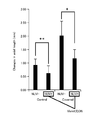
- Experiment 1 it is a graph which shows the change of the axial length of the chick which irradiated purple light, and the chick which did not irradiate purple light.
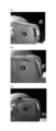
- a glass type irradiation device used in Experiment 3 (a) is an example in which an LED is provided on the outer end side, (b) is an example in which an LED is provided in the middle, and (c) is an LED. Is provided on the inner end side.
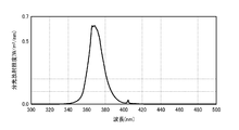
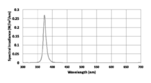
- It is the optical spectrum of the light source used in Experiment 3.
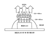
- It is a schematic diagram which shows an example of the irradiation apparatus provided with the light emitting element of the light within the range of 350 nm or more and 400 nm or less, and the light emitting element of white light.
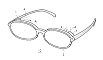
- the irradiation apparatus 10 includes a light source 1 and an instrument 2 on which the light source 1 is mounted, as shown in FIGS.
- the light source 1 emits at least light 4 having a wavelength in the range of 350 nm to 400 nm, and the light source 1 is disposed at a position where the light source 1 is irradiated in the eyeball direction A when the instrument 2 is attached.
- the light source 1 is preferably arranged at a position of 0 mm or more and 100 mm or less from the surface of the eyeball.
- the light source 1 is disposed at a position to be irradiated in the eyeball direction A when the instrument 2 is attached, and therefore, the eyeball 3 can be appropriately irradiated with the light 4 emitted from the light source 1.
- the light source 1 emits at least light 4 having a wavelength within the above range and is disposed at a position of 0 mm or more and 100 mm or less from the surface of the eyeball. Therefore, the light source 1 can accurately and effectively irradiate the eyeball. It is possible to prevent myopia or delay the progress of myopia by the action of the irradiated light.
- the term “light” is used in the meaning of an electromagnetic wave, and thus it is synonymous even if “light” is replaced with “electromagnetic wave”.
- the instrument 2 is for mounting the light source 1. By attaching the light source 1 to the instrument 2, the light 4 emitted from the light source 1 travels toward the eyeball 3.
- the instrument 2 is preferably a spectacle frame as shown in FIG. 1, but is not limited thereto.
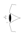
- a hat-shaped instrument as shown in FIG. 2 As the instrument 2 other than the eyeglass frame, a hat-shaped instrument as shown in FIG. 2, an ear-shaped instrument as shown in FIG. 3, or a contact-type instrument directly attached to the eyeball 3 as shown in FIG. There may be. Any device 2 can be worn on the face, head, ears, etc. close to the eyes, and can direct the light 4 emitted from the light source 1 in the direction A of the eyeball 3. As long as it is such, the instrument 2 may be other than those illustrated in FIGS.
- the light source 1 can be arranged at a position where the instrument 2 is irradiated in the eyeball direction A when the instrument 2 is worn by a person.
- the eyeball 3 can be appropriately irradiated with the light 4 emitted from the light source 1.
- the light source 1 mounted on the instrument 2 is arranged at a position of 0 mm or more and 100 mm or less from the surface of the eyeball 3.
- 0 mm from the surface of the eyeball 3 indicates a case of a contact-type mounting device in which a light source is directly mounted on the eyeball 3.
- the reason why the distance from the surface of the eyeball 3 to 100 mm or less is that if it is placed at a position exceeding 100 mm, the light source 1 moves away from the face and head, and the accuracy of irradiation to the eyeball is reduced and may interfere. Further, it is considered that the selection range of the light source 1 is reduced.
- the light source 1 is disposed at a position where the light 4 is irradiated in the eyeball direction A when the instrument 2 is worn by a person.
- the position where the light source 1 is arranged varies depending on the form of the instrument 2.
- the light source 1 can be provided on the frame.
- the position provided in the frame is not particularly limited, the light source 1 may be provided on the entire circumference of the frame, the frame upper side (top rim side), the frame outer end side (temple side), the frame inner end side (bridge side), It may be provided at any one or two or more positions on the lower side of the frame (under rim side).
- the light source 1 can be provided on the collar of the hat.
- the light source 1 can be provided on an arm portion extending from the ear.
- the light source 1 integrated with the instrument may be used.
- the light 4 emitted from the light source 1 is light having a wavelength in the range of 350 nm to 400 nm.
- the “light having a wavelength within the range of 350 nm to 400 nm” may be any wavelength within the range of 350 nm to 400 nm.
- the light may be 350 to 380 nm.
- light of 360 to 390 nm may be used.
- light of 370 to 400 nm may be used.
- light of 350 to 400 nm may be used.
- the light 4 may be any light that includes at least light having a wavelength in the range of 350 nm or more and 400 nm or less to prevent myopia (suppress generation) or suppress the progress of myopia.
- light having an optical spectrum having a peak in a wavelength range of 350 nm or more and 400 nm or less may be used.
- light having an optical spectrum that does not have a peak within a wavelength range of 350 nm or more and 400 nm or less may be used.
- “having a peak within a wavelength range of 350 nm to 400 nm” may be, for example, light having an optical spectrum having a peak at a wavelength of 365 nm or light having an optical spectrum having a peak at 380 nm.
- “having no peak in the wavelength range of 350 nm or more and 400 nm or less” means, for example, that light in the light spectrum having a peak in the wavelength of 400 nm or more emits light even in the range of 350 nm or more and 400 nm or less. That is. Note that light in the light spectrum having a peak at a wavelength of less than 350 nm may include light of 315 nm or less, which is considered to have an adverse effect on the eyes, and therefore it is desirable to exclude it in the present invention.
- the light 4 may be only light having a wavelength in the range of 350 nm to 400 nm. In this case, a little light outside the wavelength range of 350 nm or more and 400 nm or less (light having a wavelength less than 350 nm or light exceeding 400 nm) may be included. “Slightly” includes an aspect that is included as noise that is considerably smaller than the irradiance described later, and an aspect that is slightly included as the skirt portion of the optical spectrum. Although the degree is not particularly limited, it is light that prevents myopia (suppresses occurrence) or does not contribute to suppression of the progression of myopia, and is less than about 10% of the light amount in the range of 350 nm to 400 nm. be able to.
- Non-Patent Document 3 describes that outdoor activities of 14 hours or more per week greatly reduce the probability of developing myopia.
- incidental eye movements such as watching the scenery or animals and plants by being outdoors are effective, whether the body movements are effective, or whether the stress relief is effective outdoors.
- the wavelength range of light that is effective in preventing myopia has not been specified.
- the irradiance on the surface of the eyeball 3 is 0.02 W / m 2 or more in the integral value in the wavelength range of 350 nm or more and 400 nm or less. Is preferred. More preferable irradiance is 0.25 W / m 2 or more, and further preferably 0.5 W / m 2 or more.
- the spectral irradiance of sunlight was measured and calculated based on the irradiance of sunlight.
- the intensity (irradiance) of sunlight having a wavelength of 350 nm to 400 nm of sunlight is 33.3 W / m 2 according to a calculation based on international standard data (AM1.5G).
- the irradiance was 1.6 W / m 2 in the horizontal direction facing north.
- the irradiance of the light 4 emitted from the light source 1 is determined as the instrument 2. It is preferable to set it to 0.25 W / m ⁇ 2 > or more (preferably 0.5 W / m ⁇ 2 > or more) on the surface of the eyeball 3 at the time of wearing. As described above, if the irradiation time per day is lengthened, the irradiance may be less than 0.25 W / m 2 , and can be 0.02 W / m 2 or more as described above.
- the light source 1 having such irradiance a commercially available LED or the like can be selected and employed.
- a bullet-type light for example, LED “NSPU510CS” manufactured by Nichia Corporation, peak wavelength: 375 nm
- the irradiance can be controlled using a filter or the like that can control the light transmittance.
- the spectral irradiance can be measured by a spectroscope, and the integral value (irradiance) can also be calculated by integrating in the wavelength region where the spectral irradiance is desired.
- the spectral irradiance is measured as a value on the surface of the eyeball 3 when the instrument 2 is worn.
- the light source 1 attached to the instrument 2 is disposed at a position of 0 mm or more and 100 mm or less from the surface of the eyeball 3, and thus the light 4 from the light source 1 disposed within the range is the light of the eyeball 3. Evaluate at the position that reaches the position.
- the light 4 emitted from the light source 1 since the light 4 emitted from the light source 1 only needs to have a wavelength of 350 nm or more and 400 nm or less, it may be only light having a wavelength of 350 nm or more and 400 nm or less, or may include light in other wavelength ranges.
- an LED that emits only light in that range may be employed, or light other than light having a wavelength of 350 nm or more and 400 nm or less from light including light in other wavelength ranges may be employed.
- a filter that does not transmit light may be used.
- the light of the other wavelength range exceeding 400 nm may be included.
- the light source 1 may further emit light having a wavelength of 440 nm or more and 480 nm or less, or may further include another light source that emits light having a wavelength of 440 nm or more and 480 nm or less. In this case, the effect of improving the body clock can be given together.
- the light source 1 may further emit one or more kinds of light selected from red light, near infrared light, and far infrared light, or red light, near infrared light, and far light. You may further provide the other light source which emits the 1 type, or 2 or more types of light chosen from infrared light.
- the infrared region There are various definitions of the infrared region.
- red light is light having a wavelength of about 600 nm to about 780 nm
- near infrared light is about 780 nm. It is light having a wavelength of about 3,000 to 4,000 nm
- far-infrared light can be said to be light having a wavelength of more than 1000 ⁇ m.
- Red light is light having a wavelength of about 740 nm to about 780 nm
- near infrared light is about 780 nm to about 1500 nm.
- the mid-infrared light is light having a wavelength of about 1500 nm to about 5600 nm
- the far-infrared light is light having a wavelength of about 5600 nm to about 25000 nm
- the ultra-far infrared light is about It is said to be light having a wavelength of 25000 nm to about 1000 ⁇ m or less.
- the light source 1 may further emit white light, or may further include another light source that emits white light.
- the light-emitting element illustrated in FIG. 9 can be given.
- the light-emitting element illustrated in FIG. 9 includes a light-emitting element that emits excitation light having a wavelength in the range of 350 nm to 400 nm and a light-emitting element that emits white light.
- the light-emitting element includes an excitation light emitting unit (LED) that emits excitation light having a wavelength within a range of 350 nm to 400 nm, and red (Red) and green (Green) provided to cover the excitation light emitting unit. And blue (Blue) phosphors.
- the phosphor when the phosphor is irradiated with excitation light having a wavelength in the range of 350 nm or more and 400 nm or less, the phosphor emits white light composed of the three primary colors of red, green, and blue. A part of light (excitation light) having a wavelength in the range of 350 nm or more and 400 nm or less passes through the phosphor as shown in the figure.
- excitation light having a wavelength in the range of 350 nm or more and 400 nm or less passes through the phosphor as shown in the figure.
- Such a light-emitting element can be used as a white light source including light that produces a myopia-preventing effect.
- a light emitting element shown in FIG. 10 can be given.
- the light-emitting element illustrated in FIG. 10 includes a light-emitting element that emits light having a wavelength in the range of 350 nm to 400 nm, and an RGB light-emitting element that emits white light.
- This light-emitting element is an example configured with a light-emitting unit that emits light having a wavelength in the range of 350 nm to 400 nm and light-emitting units (LEDs) of R (red), G (green), and B (blue). It is. With such a configuration, it can be used as a white light source including light that produces a myopia prevention effect.
- a general RGB light emitting element can create pseudo white light close to sunlight, the white light hardly includes light having a wavelength in the range of 350 nm to 400 nm.
- the light-emitting elements shown in FIGS. 9 and 10 emit light having a wavelength in the range of 350 nm to 400 nm, and this light has a broad spectrum width as a whole and is white light (natural light) closer to sunlight.
- the light-emitting element shown in FIGS. 9 and 10 can produce a special effect of selectively emitting light having a wavelength within a range of 350 nm to 400 nm, which has a myopia preventing effect.
- White light may be emitted by the means illustrated in FIGS.
- a light emitting element (not including B) composed of R (red) and G (green) whose emission wavelength is controlled. Can be mentioned.
- the irradiation device 10 has a light source 1 and a device 2 to which the light source 1 is attached.
- the light source 1 is attached to the device 2 with an adhesive. Alternatively, it may be mechanically attached with a screw or a caulking tool.
- the power source (not shown) for supplying power to the light source 1 may be a battery embedded or attached to the instrument 2 or may be a cable that is routed to a battery attached at another position. Good. Moreover, when it does not move in one place, the form connected to a household power supply etc. may be sufficient.
- a controller for the light source 1 and a timer function may be provided.
- the controller can include a function of changing the irradiance or adjusting the irradiation angle to the eyeball.
- the timer function can mention what can set the irradiance time of light.
- Such a controller or timer function may be provided integrally with the instrument 2 or may be a separate member.
- the irradiation device 10 including the light source 1 emits at least light 4 having a wavelength within a range of 350 nm or more and 400 nm or less, and is disposed at a position that irradiates in the eyeball direction when the instrument 2 is mounted. It is arrange
- Example 1 A light irradiation experiment was conducted on chicks.
- a violet fluorescent lamp having a peak wavelength of 365 nm and a normal white fluorescent lamp (no light having a wavelength of 400 nm or less) were used.
- FIG. 5 is a graph showing the relationship between the spectral irradiance of light of the violet fluorescent lamp used in Experiment 1 and the wavelength.
- the measurement used a fiber multichannel spectrometer (Blue Wave, manufactured by StellarNet (USA)).
- StellarNet StellarNet
- FIG. 6 is a graph showing changes in the axial length of chicks irradiated with purple light and chicks not irradiated with purple light in Experiment 1.
- the axial length of the shielding eye on the 13th day (7 days after the start of shielding) was measured. Measurement of the axial length was performed in B mode using US-4000 (manufactured by Nidec Co., Ltd.). As a result, the change in the average axial length of the shielded eyes in the irradiated group is significantly smaller than the change in the average axial length of the shielded eyes in the non-irradiated group, and the degree of progression of myopia in the irradiated group is greater. It was smaller than the non-irradiated group. The same trend was seen in the control group.
- Example 2 The eyeglass type irradiation apparatus shown in FIG. 1 was produced.
- a button-type light (LED “NSSU123T” manufactured by Nichia Corporation, peak wavelength measurement value: 373 nm) is attached to a glasses-type frame, and electric so that its irradiance is 0.25 W / m 2. Set.
- an irradiation apparatus according to the present invention was produced.
- the household AC power supply was used for the electric power supply to a light source.
- FIG. 7 The eyeglass type irradiation apparatus shown in FIG. 7 was produced.
- a light source an LED manufactured by Nichia Corporation (“NSSU123T”, measured value of peak wavelength: 373 nm) was mounted on a lensless frame.
- FIG. 7A shows an example in which LEDs are provided on the temple side (outer frame end side) of the top rim (upper frame side)
- FIG. 7B shows an example in which LEDs are provided at an intermediate position on the top rim (upper frame side)
- FIG. 7C shows an example in which LEDs are provided on the bridge side (frame inner end side) of the top rim (frame upper side).
- FIG. 8 shows the light spectrum of the light source, which was measured with a fiber multichannel spectrometer (Blue Wave, manufactured by StellarNet (USA)).
- This eyeglass-type irradiation device was attached to a mannequin doll, and the irradiance on the eyeball surface was measured.
- the irradiance was measured with the spectroscopic probe installed on the eyeball surface.
- the distance from the light source (see FIG. 7) provided on the frame to the eyeball is about 3 cm in the case of FIG. 7A, about 2 cm in the case of FIG. 7B, and in the case of FIG. Was about 2.5 cm.
- Table 1 shows the voltage applied to the LED and the measurement result of the irradiance at that time.
Landscapes
- Health & Medical Sciences (AREA)
- Engineering & Computer Science (AREA)
- Biomedical Technology (AREA)
- Life Sciences & Earth Sciences (AREA)
- Animal Behavior & Ethology (AREA)
- General Health & Medical Sciences (AREA)
- Public Health (AREA)
- Veterinary Medicine (AREA)
- Ophthalmology & Optometry (AREA)
- Nuclear Medicine, Radiotherapy & Molecular Imaging (AREA)
- Radiology & Medical Imaging (AREA)
- Pathology (AREA)
- Vascular Medicine (AREA)
- Heart & Thoracic Surgery (AREA)
- Epidemiology (AREA)
- Pain & Pain Management (AREA)
- Physical Education & Sports Medicine (AREA)
- Rehabilitation Therapy (AREA)
- Radiation-Therapy Devices (AREA)
- Rehabilitation Tools (AREA)
Abstract
Description
器具2は、図1~図4に示すように、光源1を装着するものである。この器具2に光源1が装着されることにより、光源1から発した光4が眼球3に向かう。器具2としては、図1に示すようなめがねフレームを好ましく挙げることができるが、これに限定されない。
光源1は、器具2を人が装着した際に、光4を眼球方向Aに照射する位置に配置されている。光源1を配置する位置は、器具2の形態によって異なり、例えば図1のめがね型の器具ではフレームに光源1を設けることができる。フレームに設ける位置は特に限定されないが、光源1をフレームの全周に設けてもよいし、フレーム上側(トップリム側)、フレーム外端側(テンプル側)、フレーム内端側(ブリッジ側)、フレーム下側(アンダーリム側)の四方のいずれか1又は2以上の位置に設けてもよい。図2の帽子型の器具では、帽子のつば等に光源1を設けることができる。図3の耳掛け型の器具では、耳から伸びるアーム部に光源1を設けることができる。図4の眼球へのコンタクト型の器具では、その器具と一体型の光源1としてもよい。
光源1から発する光4は、少なくとも波長が350nm以上400nm以下であればよいので、350nm以上400nm以下の波長の光だけであってもよいし、他の波長域の光を含んでいてもよい。350nm以上400nm以下の波長の光だけの場合は、その範囲の光だけを発光するLEDを採用してもよいし、他の波長域の光を含む光から350nm以上400nm以下の波長の光以外の光を透過させないフィルター(光吸収フィルター)を用いたものであってもよい。また、400nmを超える他の波長域の光を含んでいてもよい。
照射装置10は、図1~図4に示すように、光源1と、その光源1を装着する器具2とを有しているが、器具2への光源1の取り付けは、接着剤で取り付けてもよいし、ネジやカシメ具で機械的に取り付けてもよい。また、光源1に電力を供給するための電源(図示しない)は、器具2に埋設又は装着したバッテリーであってもよいし、別の位置に装着したバッテリーまでケーブルで引き回したものであってもよい。また、一箇所で動かない場合には、家庭用電源等に接続する形態であってもよい。
ヒヨコへの光の照射実験を行った。光源は、ピーク波長365nmの紫色光蛍光灯と、通常の白色蛍光灯(400nm以下の光は発していない)とを用いた。図5は、実験1で用いた紫色光蛍光灯の光の分光放射照度と波長との関係を示すグラフである。測定はファイバーマルチチャンネル分光器(StellarNet社(米国)製、Blue Wave)を用いた。ヒヨコは、片目を透明半球で覆うとその眼(遮蔽眼)が近視化することが知られている(例えば、Seko et. al., Invest. Ophthalmol. Vis. Sci. May、1995, vol.36, no.6, p.1183-1187参照)。そこで、生後6日のホワイトレグホン種のヒヨコの片目を透明半球で覆い、当該紫色光を照射しない非照射群15羽と、当該紫色光を照射した照射群15羽とに分けて実験を行った。ヒヨコの眼の高さにおける水平方向の平均放射照度を4.12W/m2とし、1日を明暗12時間ずつとして7日間継続し、遮蔽眼の近視化の度合いを調べた。白色蛍光灯は、両群共に照射した。透明半球で覆っていない方の眼をコントロール眼と呼ぶ。図6は、実験1において、紫色光を照射したヒヨコと紫色光を照射しなかったヒヨコの眼軸長の変化を示すグラフである。
図1に示すめがね型の照射装置を作製した。めがね型のフレームに、ボタン型のライト(日亜化学株式会社製のLED「NSSU123T」、ピーク波長の測定値:373nm)を装着し、その放射照度が0.25W/m2となるように電気的に設定した。こうして本発明に係る照射装置を作製した。なお、光源への電力供給は、家庭用交流電源を用いた。
図7に示すめがね型の照射装置を作製した。光源は、日亜化学株式会社製のLED(「NSSU123T」、ピーク波長の測定値:373nm)をレンズ無しフレームに装着した。図7(a)はLEDをトップリム(フレーム上側)のテンプル側(フレーム外端側)に設けた例であり、図7(b)はLEDをトップリム(フレーム上側)中間位置に設けた例であり、図7(c)はLEDをトップリム(フレーム上側)のブリッジ側(フレーム内端側)に設けた例である。図8は、光源の光スペクトラムであり、ファイバーマルチチャンネル分光器(StellarNet社(米国)製、Blue Wave)で測定した。

2 器具
3 眼球
4 光
10 照射装置
A 眼球方向
Claims (6)
- 光源と、当該光源を装着する器具とを有する照射装置であって、
前記光源は、350nm以上400nm以下の範囲内の波長の光を少なくとも発するとともに、前記器具を装着した際に眼球方向に照射する位置に配置されており、
前記光源が、眼球の表面から0mm以上100mm以下の位置に配置されている、ことを特徴とする照射装置。 - 前記光源は、440nm以上480nm以下の波長の光をさらに発する、又は、440nm以上480nm以下の波長の光を発する他の光源をさらに備える、請求項1に記載の照射装置。
- 前記光源は、赤色光、近赤外光及び遠赤外光から選ばれる1種又は2種以上の光をさらに発する、又は、赤色光、近赤外光及び遠赤外光から選ばれる1種又は2種以上の光を発する他の光源をさらに備える、請求項1に記載の照射装置。
- 前記光源は、白色光をさらに発する、又は、白色光を発する光源をさらに備える、請求項1に記載の照射装置。
- 前記350nm以上400nm以下の範囲内の波長の光の放射照度が、前記器具を装着した際の眼球表面で0.02W/m2以上、1.0W/m2以下である、請求項1に記載の照射装置。
- 前記器具がめがね型である、請求項1~5のいずれか1項に記載の照射装置
Priority Applications (6)
| Application Number | Priority Date | Filing Date | Title |
|---|---|---|---|
| KR1020187015633A KR102639025B1 (ko) | 2015-12-02 | 2016-12-02 | 조사 장치 |
| CN201680070809.9A CN108289755A (zh) | 2015-12-02 | 2016-12-02 | 照射装置 |
| SG11201804718UA SG11201804718UA (en) | 2015-12-02 | 2016-12-02 | Irradiation device |
| JP2017522992A JP6175210B1 (ja) | 2015-12-02 | 2016-12-02 | 照射装置 |
| EP16870821.2A EP3384881B1 (en) | 2015-12-02 | 2016-12-02 | Irradiation device |
| US15/996,842 US20180280718A1 (en) | 2015-12-02 | 2018-06-04 | Irradiation device |
Applications Claiming Priority (2)
| Application Number | Priority Date | Filing Date | Title |
|---|---|---|---|
| JP2015-236171 | 2015-12-02 | ||
| JP2015236171 | 2015-12-02 |
Related Child Applications (1)
| Application Number | Title | Priority Date | Filing Date |
|---|---|---|---|
| US15/996,842 Continuation-In-Part US20180280718A1 (en) | 2015-12-02 | 2018-06-04 | Irradiation device |
Publications (1)
| Publication Number | Publication Date |
|---|---|
| WO2017094886A1 true WO2017094886A1 (ja) | 2017-06-08 |
Family
ID=58797395
Family Applications (1)
| Application Number | Title | Priority Date | Filing Date |
|---|---|---|---|
| PCT/JP2016/085903 Ceased WO2017094886A1 (ja) | 2015-12-02 | 2016-12-02 | 照射装置 |
Country Status (8)
| Country | Link |
|---|---|
| US (1) | US20180280718A1 (ja) |
| EP (1) | EP3384881B1 (ja) |
| JP (1) | JP6175210B1 (ja) |
| KR (1) | KR102639025B1 (ja) |
| CN (1) | CN108289755A (ja) |
| SG (1) | SG11201804718UA (ja) |
| TW (1) | TWI717429B (ja) |
| WO (1) | WO2017094886A1 (ja) |
Cited By (20)
| Publication number | Priority date | Publication date | Assignee | Title |
|---|---|---|---|---|
| WO2019181967A1 (ja) * | 2018-03-21 | 2019-09-26 | 株式会社坪田ラボ | 非侵襲的角膜・強膜強化装置及び方法 |
| WO2019209063A1 (ko) * | 2018-04-27 | 2019-10-31 | 서울바이오시스 주식회사 | 안구 치료용 광원 및 이를 포함하는 안구 치료 장치 |
| JP2020058802A (ja) * | 2018-10-09 | 2020-04-16 | 株式会社坪田ラボ | 近視治療用の装置 |
| JP2020065252A (ja) * | 2018-10-17 | 2020-04-23 | 東海光学株式会社 | 画像投影装置、展示装置、評価装置、評価方法及び評価システム |
| CN112135589A (zh) * | 2018-05-10 | 2020-12-25 | 奥克塞拉有限公司 | 治疗眼睛屈光不正的方法和装置 |
| JP2021049203A (ja) * | 2019-09-25 | 2021-04-01 | 株式会社坪田ラボ | 内因性リボフラビンに基づく非侵襲的角膜及び強膜強膜の強化装置 |
| US11460720B1 (en) | 2021-05-04 | 2022-10-04 | Acucela Inc. | Electronic case for electronic spectacles |
| US11467423B2 (en) | 2020-06-10 | 2022-10-11 | Acucela Inc. | Methods for the treatment of refractive error using active stimulation |
| US11467428B2 (en) | 2020-05-13 | 2022-10-11 | Acucela Inc. | Electro-switchable spectacles for myopia treatment |
| US11497931B2 (en) | 2020-06-08 | 2022-11-15 | Acucela Inc. | Lens with asymmetric projection to treat astigmatism |
| US11531216B2 (en) | 2021-04-06 | 2022-12-20 | Acucela Inc. | Supporting pillars for encapsulating a flexible PCB within a soft hydrogel contact lens |
| US11583696B2 (en) | 2019-07-31 | 2023-02-21 | Acucela Inc. | Device for projecting images on the retina |
| US11619831B2 (en) | 2018-07-30 | 2023-04-04 | Acucela Inc. | Optical designs of electronic apparatus to decrease myopia progression |
| US11624937B2 (en) | 2018-07-07 | 2023-04-11 | Acucela Inc. | Device to prevent retinal hypoxia |
| US11719957B2 (en) | 2020-06-08 | 2023-08-08 | Acucela Inc. | Stick on devices using peripheral defocus to treat progressive refractive error |
| US11733545B2 (en) | 2019-09-16 | 2023-08-22 | Acucela Inc. | Assembly process for an electronic soft contact lens designed to inhibit progression of myopia |
| US11777340B2 (en) | 2020-02-21 | 2023-10-03 | Acucela Inc. | Charging case for electronic contact lens |
| WO2024204838A1 (ja) * | 2023-03-31 | 2024-10-03 | 株式会社坪田ラボ | 赤色光照射装置 |
| JP2025073124A (ja) * | 2021-04-27 | 2025-05-12 | 京セラ株式会社 | 光照射システム、光照射装置、制御方法、および制御プログラム |
| US12474598B2 (en) | 2020-06-08 | 2025-11-18 | Acucela Inc. | Projection of defocused images on the peripheral retina to treat refractive error |
Families Citing this family (11)
| Publication number | Priority date | Publication date | Assignee | Title |
|---|---|---|---|---|
| US10512586B1 (en) * | 2018-07-12 | 2019-12-24 | Rayer Lavonne Lee | System and method for vision rehabilitation therapy |
| EP3830637A1 (en) * | 2018-07-31 | 2021-06-09 | Essilor International | Optical systems, spectacle lens and eyewear including the same |
| KR102235252B1 (ko) * | 2018-09-27 | 2021-04-02 | 한양대학교 에리카산학협력단 | 근시의 진행을 억제하는 led 조명 |
| CN112657063B (zh) * | 2019-10-15 | 2023-01-31 | 林纯益 | 对眼球及其外围组织照明的防近视照明器具 |
| US11801396B1 (en) * | 2020-03-10 | 2023-10-31 | Cosmo Haralambidis | Wearable device including UVC light source for reduction in virus and bacteria transmission |
| TWI722945B (zh) * | 2020-07-21 | 2021-03-21 | 林芸萱 | 具紅光及近紅外光多波段眼部活化裝置及其操作方法 |
| FR3114494A1 (fr) * | 2020-09-25 | 2022-04-01 | Chwen-Yih Lin | Anti-myopie destiné à éclairer les globes oculaires et les tissus environnants par de la lumière qui pénètre dans la peau périorbitaire, le tissu sous-cutané, puis qui passe à travers la cornée, l'iris, l'uvée, la sclère et la choroïde |
| GB2600713A (en) * | 2020-11-05 | 2022-05-11 | Chwen Yih Lin | Myopia-preventing illumination apparatus for illuminating eyeballs and surrounding tissues via light that penetrates periorbital skin and subcutaneous tissue, |
| CN114794637B (zh) * | 2022-04-15 | 2026-02-24 | 至善时代智能科技(北京)有限公司 | 一种多功能帽子 |
| PH12023050462A1 (en) | 2022-09-06 | 2024-04-22 | Lin Chwen Yih | Myopia-preventing high intensity illumination apparatus for illuminating eyeballs and surrounding tissue by extra pupillary pathway via light that penetrating periorbital skin, subcutaneous tissue, pass through peripheral cornea, iris, peripheral lens, uvea, sclera, choroid, retinal pigment epithelium |
| CN121586863A (zh) * | 2023-07-25 | 2026-02-27 | 明志科技大学 | 微光眼镜 |
Citations (4)
| Publication number | Priority date | Publication date | Assignee | Title |
|---|---|---|---|---|
| JP3002145U (ja) * | 1994-02-18 | 1994-09-20 | 紀雄 三井 | 視力回復訓練装置 |
| JP2006506111A (ja) * | 2002-11-14 | 2006-02-23 | クイーンスランド ユニバーシティー オブ テクノロジー | 人間の近眼の発現を阻止する方法および装置 |
| JP2010506601A (ja) * | 2006-07-13 | 2010-03-04 | エレカー,サティシュ・ヴイ | 光化学的眼球形成術/角膜形成術の方法及び装置 |
| JP2014514038A (ja) * | 2011-03-15 | 2014-06-19 | ポリフォトニクス リミテッド | カートリッジ、医療用装置及びその使用方法 |
Family Cites Families (13)
| Publication number | Priority date | Publication date | Assignee | Title |
|---|---|---|---|---|
| ATE427725T1 (de) * | 2004-02-03 | 2009-04-15 | Iroc Ag | Ophtalmologische vorrichtung |
| US20060206171A1 (en) * | 2005-03-14 | 2006-09-14 | Michael Gertner | Devices, methods and kits for radiation treatment via a target body surface |
| WO2008131343A1 (en) * | 2007-04-19 | 2008-10-30 | Mergenet Medical, Inc. | Temporal control in phototherapy |
| WO2009042159A1 (en) * | 2007-09-24 | 2009-04-02 | The Johns Hopkins University | Wearable photoactivator for ocular therapeutic applications and use thereof |
| CN103764080B (zh) * | 2011-04-29 | 2017-06-30 | 法尔哈德·哈菲泽 | 用于角膜疾病治疗和/或预防的设备 |
| US9020580B2 (en) * | 2011-06-02 | 2015-04-28 | Avedro, Inc. | Systems and methods for monitoring time based photo active agent delivery or photo active marker presence |
| WO2014047517A1 (en) * | 2012-09-20 | 2014-03-27 | Myolite, Inc. | Protective lighting system |
| CN203178600U (zh) * | 2013-03-13 | 2013-09-04 | 潘学龙 | 脑眼声光近视弱视防治眼镜 |
| CN105431201B (zh) * | 2013-07-25 | 2019-06-18 | 皇家飞利浦有限公司 | 用于提供光疗和调节昼夜节律的系统和方法 |
| CN203705735U (zh) * | 2014-01-15 | 2014-07-09 | 上海适目医疗科技有限公司 | 一种湿房镜 |
| TWI704908B (zh) * | 2014-06-03 | 2020-09-21 | 日商坪田實驗室股份有限公司 | 預防近視物品,以及預防近視物品的套組 |
| US20160067087A1 (en) * | 2014-09-09 | 2016-03-10 | LumiThera, Inc. | Wearable devices and methods for multi-wavelength photobiomodulation for ocular treatments |
| CN104908482A (zh) * | 2015-05-28 | 2015-09-16 | 四川新华印刷有限责任公司 | 一种预防近视的黄色簿本 |
-
2016
- 2016-12-02 TW TW105139931A patent/TWI717429B/zh active
- 2016-12-02 WO PCT/JP2016/085903 patent/WO2017094886A1/ja not_active Ceased
- 2016-12-02 CN CN201680070809.9A patent/CN108289755A/zh active Pending
- 2016-12-02 EP EP16870821.2A patent/EP3384881B1/en active Active
- 2016-12-02 JP JP2017522992A patent/JP6175210B1/ja active Active
- 2016-12-02 KR KR1020187015633A patent/KR102639025B1/ko active Active
- 2016-12-02 SG SG11201804718UA patent/SG11201804718UA/en unknown
-
2018
- 2018-06-04 US US15/996,842 patent/US20180280718A1/en not_active Abandoned
Patent Citations (4)
| Publication number | Priority date | Publication date | Assignee | Title |
|---|---|---|---|---|
| JP3002145U (ja) * | 1994-02-18 | 1994-09-20 | 紀雄 三井 | 視力回復訓練装置 |
| JP2006506111A (ja) * | 2002-11-14 | 2006-02-23 | クイーンスランド ユニバーシティー オブ テクノロジー | 人間の近眼の発現を阻止する方法および装置 |
| JP2010506601A (ja) * | 2006-07-13 | 2010-03-04 | エレカー,サティシュ・ヴイ | 光化学的眼球形成術/角膜形成術の方法及び装置 |
| JP2014514038A (ja) * | 2011-03-15 | 2014-06-19 | ポリフォトニクス リミテッド | カートリッジ、医療用装置及びその使用方法 |
Non-Patent Citations (1)
| Title |
|---|
| STEPHEN B. PREPAS: "Light, literacy and the absence of ultraviolet radiation in the development of myopia", MEDICAL HYPOTHESES, vol. 70, no. 3, 4 September 2007 (2007-09-04), pages 635 - 637, XP022449003 * |
Cited By (40)
| Publication number | Priority date | Publication date | Assignee | Title |
|---|---|---|---|---|
| JP6653898B1 (ja) * | 2018-03-21 | 2020-02-26 | 株式会社坪田ラボ | 非侵襲的角膜又は強膜強化装置 |
| WO2019181967A1 (ja) * | 2018-03-21 | 2019-09-26 | 株式会社坪田ラボ | 非侵襲的角膜・強膜強化装置及び方法 |
| US20210023384A1 (en) * | 2018-03-21 | 2021-01-28 | Tsubota Laboratory, Inc. | Non-invasive cornea and sclera strengthening device and method |
| WO2019209063A1 (ko) * | 2018-04-27 | 2019-10-31 | 서울바이오시스 주식회사 | 안구 치료용 광원 및 이를 포함하는 안구 치료 장치 |
| KR102805850B1 (ko) * | 2018-05-10 | 2025-05-09 | 어큐셀라 인코포레이티드 | 눈의 굴절 이상을 치료하기 위한 방법 및 장치 |
| US12226647B2 (en) | 2018-05-10 | 2025-02-18 | Acucela Inc. | Method and apparatus for treating refractive error of the eye |
| CN112135589A (zh) * | 2018-05-10 | 2020-12-25 | 奥克塞拉有限公司 | 治疗眼睛屈光不正的方法和装置 |
| JP7627118B2 (ja) | 2018-05-10 | 2025-02-05 | アキュセラ インコーポレイテッド | 眼の屈折異常を処置するための方法および装置 |
| KR20210040284A (ko) * | 2018-05-10 | 2021-04-13 | 어큐셀라 인코포레이티드 | 눈의 굴절 이상을 치료하기 위한 방법 및 장치 |
| JP2021522925A (ja) * | 2018-05-10 | 2021-09-02 | アキュセラ インコーポレイテッド | 眼の屈折異常を処置するための方法および装置 |
| EP3799562A4 (en) * | 2018-05-10 | 2022-05-18 | Acucela Inc. | Method and apparatus for treating refractive error of the eye |
| US11624937B2 (en) | 2018-07-07 | 2023-04-11 | Acucela Inc. | Device to prevent retinal hypoxia |
| US12210225B2 (en) | 2018-07-30 | 2025-01-28 | Acucela Inc. | Optical designs of electronic apparatus to decrease myopia progression |
| US11619831B2 (en) | 2018-07-30 | 2023-04-04 | Acucela Inc. | Optical designs of electronic apparatus to decrease myopia progression |
| JP2020058802A (ja) * | 2018-10-09 | 2020-04-16 | 株式会社坪田ラボ | 近視治療用の装置 |
| JP7396628B2 (ja) | 2018-10-17 | 2023-12-12 | 東海光学株式会社 | 画像投影装置、展示装置、評価装置、評価方法及び評価システム |
| JP2020065252A (ja) * | 2018-10-17 | 2020-04-23 | 東海光学株式会社 | 画像投影装置、展示装置、評価装置、評価方法及び評価システム |
| US11986669B2 (en) | 2019-07-31 | 2024-05-21 | Acucela Inc. | Device for projecting images on the retina |
| US11583696B2 (en) | 2019-07-31 | 2023-02-21 | Acucela Inc. | Device for projecting images on the retina |
| US12427336B2 (en) | 2019-07-31 | 2025-09-30 | Acucela Inc. | Device for projecting images on the retina |
| US11733545B2 (en) | 2019-09-16 | 2023-08-22 | Acucela Inc. | Assembly process for an electronic soft contact lens designed to inhibit progression of myopia |
| JP2021049203A (ja) * | 2019-09-25 | 2021-04-01 | 株式会社坪田ラボ | 内因性リボフラビンに基づく非侵襲的角膜及び強膜強膜の強化装置 |
| US11777340B2 (en) | 2020-02-21 | 2023-10-03 | Acucela Inc. | Charging case for electronic contact lens |
| US11971615B2 (en) | 2020-05-13 | 2024-04-30 | Acucela Inc. | Electro-switchable spectacles for myopia treatment |
| US11467428B2 (en) | 2020-05-13 | 2022-10-11 | Acucela Inc. | Electro-switchable spectacles for myopia treatment |
| US11497931B2 (en) | 2020-06-08 | 2022-11-15 | Acucela Inc. | Lens with asymmetric projection to treat astigmatism |
| US11719957B2 (en) | 2020-06-08 | 2023-08-08 | Acucela Inc. | Stick on devices using peripheral defocus to treat progressive refractive error |
| US12105362B2 (en) | 2020-06-08 | 2024-10-01 | Acucela Inc. | Stick on devices using peripheral defocus to treat progressive refractive error |
| US12474598B2 (en) | 2020-06-08 | 2025-11-18 | Acucela Inc. | Projection of defocused images on the peripheral retina to treat refractive error |
| US11693259B2 (en) | 2020-06-10 | 2023-07-04 | Acucela Inc. | Methods for the treatment of refractive error using active stimulation |
| US12085786B2 (en) | 2020-06-10 | 2024-09-10 | Acucela Inc. | Apparatus for the treatment of refractive error using active stimulation |
| US11467423B2 (en) | 2020-06-10 | 2022-10-11 | Acucela Inc. | Methods for the treatment of refractive error using active stimulation |
| US12147092B2 (en) | 2021-04-06 | 2024-11-19 | Acucela Inc. | Supporting pillars for encapsulating a flexible PCB within a soft hydrogel contact lens |
| US11531216B2 (en) | 2021-04-06 | 2022-12-20 | Acucela Inc. | Supporting pillars for encapsulating a flexible PCB within a soft hydrogel contact lens |
| JP2025073124A (ja) * | 2021-04-27 | 2025-05-12 | 京セラ株式会社 | 光照射システム、光照射装置、制御方法、および制御プログラム |
| US12216343B2 (en) | 2021-05-04 | 2025-02-04 | Acucela Inc. | Electronic case for electronic spectacles |
| US11860454B2 (en) | 2021-05-04 | 2024-01-02 | Acucela Inc. | Electronic case for electronic spectacles |
| US11630329B2 (en) | 2021-05-04 | 2023-04-18 | Acucela Inc. | Electronic case for electronic spectacles |
| US11460720B1 (en) | 2021-05-04 | 2022-10-04 | Acucela Inc. | Electronic case for electronic spectacles |
| WO2024204838A1 (ja) * | 2023-03-31 | 2024-10-03 | 株式会社坪田ラボ | 赤色光照射装置 |
Also Published As
| Publication number | Publication date |
|---|---|
| TWI717429B (zh) | 2021-02-01 |
| EP3384881A4 (en) | 2019-01-02 |
| JPWO2017094886A1 (ja) | 2017-12-07 |
| JP6175210B1 (ja) | 2017-08-02 |
| KR102639025B1 (ko) | 2024-02-20 |
| SG11201804718UA (en) | 2018-07-30 |
| US20180280718A1 (en) | 2018-10-04 |
| CN108289755A (zh) | 2018-07-17 |
| EP3384881A1 (en) | 2018-10-10 |
| KR20180089422A (ko) | 2018-08-08 |
| TW201726083A (zh) | 2017-08-01 |
| EP3384881B1 (en) | 2019-07-03 |
Similar Documents
| Publication | Publication Date | Title |
|---|---|---|
| JP6175210B1 (ja) | 照射装置 | |
| Cougnard-Gregoire et al. | Blue light exposure: ocular hazards and prevention—a narrative review | |
| US10133092B2 (en) | Myopia prevention device | |
| US10823982B2 (en) | Myopia treatment device | |
| Alzahrani et al. | Modelling the effect of commercially available blue‐blocking lenses on visual and non‐visual functions | |
| US20210001145A1 (en) | Controlling myopia in humans | |
| Rabbetts et al. | Technical report: solar ultraviolet protection from sunglasses | |
| US20240184144A1 (en) | Electromagnetic waves modulating filter | |
| EP2085798A1 (en) | Lighting device with prophylactic and therapeutic filter for healthy eyes, pseudoaphakic eyes and/or eyes suffering neurodegeneration | |
| JP2020058802A (ja) | 近視治療用の装置 | |
| Rosenfield | Living with blue light exposure | |
| Good | Light and eye damage | |
| JP2014198096A (ja) | 光刺激装置 | |
| HK1261739B (en) | Irradiation device | |
| HK1261739A1 (en) | Irradiation device | |
| Shuker et al. | Study the effect of harmful radiation on patients, eyes from 15-25 years during using smart devices | |
| WO2024204838A1 (ja) | 赤色光照射装置 | |
| Takao | Health effects of occupational exposure to LED light: A special reference to plant cultivation works in plant factories | |
| Masili et al. | Evaluation of solar ultraviolet blocking by sunglasses and their compliance with recommended safety limits | |
| Coroneo et al. | The sun and eyes: sunlight-induced eye disease and its prevention | |
| LUNGU et al. | Some considerations regarding the use of protective lenses in computer activities | |
| Sliney | Light and Eye Safety | |
| CN112657063A (zh) | 对眼球及其外围组织照明的防近视照明器具 | |
| HK1139465A (en) | Lighting device with prophylactic and therapeutic filter for healthy eyes, pseudoaphakic eyes and/or eyes suffering neurodegeneration |
Legal Events
| Date | Code | Title | Description |
|---|---|---|---|
| ENP | Entry into the national phase |
Ref document number: 2017522992 Country of ref document: JP Kind code of ref document: A |
|
| 121 | Ep: the epo has been informed by wipo that ep was designated in this application |
Ref document number: 16870821 Country of ref document: EP Kind code of ref document: A1 |
|
| ENP | Entry into the national phase |
Ref document number: 20187015633 Country of ref document: KR Kind code of ref document: A |
|
| WWE | Wipo information: entry into national phase |
Ref document number: 11201804718U Country of ref document: SG |
|
| NENP | Non-entry into the national phase |
Ref country code: DE |
|
| WWE | Wipo information: entry into national phase |
Ref document number: 2016870821 Country of ref document: EP |
|
| ENP | Entry into the national phase |
Ref document number: 2016870821 Country of ref document: EP Effective date: 20180702 |