WO2017097084A1 - 一种dmrs指示方法、终端及基站 - Google Patents
一种dmrs指示方法、终端及基站 Download PDFInfo
- Publication number
- WO2017097084A1 WO2017097084A1 PCT/CN2016/105095 CN2016105095W WO2017097084A1 WO 2017097084 A1 WO2017097084 A1 WO 2017097084A1 CN 2016105095 W CN2016105095 W CN 2016105095W WO 2017097084 A1 WO2017097084 A1 WO 2017097084A1
- Authority
- WO
- WIPO (PCT)
- Prior art keywords
- terminal
- dmrs
- scheduled
- scheduling resource
- terminals
- Prior art date
- Legal status (The legal status is an assumption and is not a legal conclusion. Google has not performed a legal analysis and makes no representation as to the accuracy of the status listed.)
- Ceased
Links
Images


Classifications
-
- H—ELECTRICITY
- H04—ELECTRIC COMMUNICATION TECHNIQUE
- H04L—TRANSMISSION OF DIGITAL INFORMATION, e.g. TELEGRAPHIC COMMUNICATION
- H04L1/00—Arrangements for detecting or preventing errors in the information received
- H04L1/12—Arrangements for detecting or preventing errors in the information received by using return channel
- H04L1/16—Arrangements for detecting or preventing errors in the information received by using return channel in which the return channel carries supervisory signals, e.g. repetition request signals
- H04L1/18—Automatic repetition systems, e.g. Van Duuren systems
-
- H—ELECTRICITY
- H04—ELECTRIC COMMUNICATION TECHNIQUE
- H04L—TRANSMISSION OF DIGITAL INFORMATION, e.g. TELEGRAPHIC COMMUNICATION
- H04L25/00—Baseband systems
- H04L25/02—Details ; arrangements for supplying electrical power along data transmission lines
- H04L25/0202—Channel estimation
-
- H—ELECTRICITY
- H04—ELECTRIC COMMUNICATION TECHNIQUE
- H04L—TRANSMISSION OF DIGITAL INFORMATION, e.g. TELEGRAPHIC COMMUNICATION
- H04L1/00—Arrangements for detecting or preventing errors in the information received
- H04L1/12—Arrangements for detecting or preventing errors in the information received by using return channel
- H04L1/16—Arrangements for detecting or preventing errors in the information received by using return channel in which the return channel carries supervisory signals, e.g. repetition request signals
- H04L1/18—Automatic repetition systems, e.g. Van Duuren systems
- H04L1/1806—Go-back-N protocols
-
- H—ELECTRICITY
- H04—ELECTRIC COMMUNICATION TECHNIQUE
- H04L—TRANSMISSION OF DIGITAL INFORMATION, e.g. TELEGRAPHIC COMMUNICATION
- H04L27/00—Modulated-carrier systems
- H04L27/26—Systems using multi-frequency codes
- H04L27/2601—Multicarrier modulation systems
- H04L27/2602—Signal structure
- H04L27/261—Details of reference signals
- H04L27/2613—Structure of the reference signals
-
- H—ELECTRICITY
- H04—ELECTRIC COMMUNICATION TECHNIQUE
- H04L—TRANSMISSION OF DIGITAL INFORMATION, e.g. TELEGRAPHIC COMMUNICATION
- H04L5/00—Arrangements affording multiple use of the transmission path
- H04L5/003—Arrangements for allocating sub-channels of the transmission path
- H04L5/0048—Allocation of pilot signals, i.e. of signals known to the receiver
- H04L5/0051—Allocation of pilot signals, i.e. of signals known to the receiver of dedicated pilots, i.e. pilots destined for a single user or terminal
-
- H—ELECTRICITY
- H04—ELECTRIC COMMUNICATION TECHNIQUE
- H04L—TRANSMISSION OF DIGITAL INFORMATION, e.g. TELEGRAPHIC COMMUNICATION
- H04L5/00—Arrangements affording multiple use of the transmission path
- H04L5/0091—Signalling for the administration of the divided path, e.g. signalling of configuration information
- H04L5/0094—Indication of how sub-channels of the path are allocated
-
- H—ELECTRICITY
- H04—ELECTRIC COMMUNICATION TECHNIQUE
- H04L—TRANSMISSION OF DIGITAL INFORMATION, e.g. TELEGRAPHIC COMMUNICATION
- H04L5/00—Arrangements affording multiple use of the transmission path
- H04L5/02—Channels characterised by the type of signal
- H04L5/06—Channels characterised by the type of signal the signals being represented by different frequencies
- H04L5/10—Channels characterised by the type of signal the signals being represented by different frequencies with dynamo-electric generation of carriers; with mechanical filters or demodulators
-
- H—ELECTRICITY
- H04—ELECTRIC COMMUNICATION TECHNIQUE
- H04W—WIRELESS COMMUNICATION NETWORKS
- H04W72/00—Local resource management
- H04W72/12—Wireless traffic scheduling
- H04W72/121—Wireless traffic scheduling for groups of terminals or users
-
- H—ELECTRICITY
- H04—ELECTRIC COMMUNICATION TECHNIQUE
- H04W—WIRELESS COMMUNICATION NETWORKS
- H04W72/00—Local resource management
- H04W72/20—Control channels or signalling for resource management
- H04W72/23—Control channels or signalling for resource management in the downlink direction of a wireless link, i.e. towards a terminal
-
- H—ELECTRICITY
- H04—ELECTRIC COMMUNICATION TECHNIQUE
- H04W—WIRELESS COMMUNICATION NETWORKS
- H04W72/00—Local resource management
- H04W72/50—Allocation or scheduling criteria for wireless resources
- H04W72/54—Allocation or scheduling criteria for wireless resources based on quality criteria
- H04W72/541—Allocation or scheduling criteria for wireless resources based on quality criteria using the level of interference
-
- H—ELECTRICITY
- H04—ELECTRIC COMMUNICATION TECHNIQUE
- H04W—WIRELESS COMMUNICATION NETWORKS
- H04W76/00—Connection management
- H04W76/20—Manipulation of established connections
- H04W76/27—Transitions between radio resource control [RRC] states
-
- H—ELECTRICITY
- H04—ELECTRIC COMMUNICATION TECHNIQUE
- H04B—TRANSMISSION
- H04B7/00—Radio transmission systems, i.e. using radiation field
- H04B7/02—Diversity systems; Multi-antenna system, i.e. transmission or reception using multiple antennas
- H04B7/04—Diversity systems; Multi-antenna system, i.e. transmission or reception using multiple antennas using two or more spaced independent antennas
- H04B7/0413—MIMO systems
- H04B7/0452—Multi-user MIMO systems
-
- H—ELECTRICITY
- H04—ELECTRIC COMMUNICATION TECHNIQUE
- H04L—TRANSMISSION OF DIGITAL INFORMATION, e.g. TELEGRAPHIC COMMUNICATION
- H04L1/00—Arrangements for detecting or preventing errors in the information received
- H04L1/12—Arrangements for detecting or preventing errors in the information received by using return channel
- H04L1/16—Arrangements for detecting or preventing errors in the information received by using return channel in which the return channel carries supervisory signals, e.g. repetition request signals
- H04L1/1607—Details of the supervisory signal
-
- H—ELECTRICITY
- H04—ELECTRIC COMMUNICATION TECHNIQUE
- H04L—TRANSMISSION OF DIGITAL INFORMATION, e.g. TELEGRAPHIC COMMUNICATION
- H04L5/00—Arrangements affording multiple use of the transmission path
- H04L5/003—Arrangements for allocating sub-channels of the transmission path
- H04L5/0058—Allocation criteria
- H04L5/0073—Allocation arrangements that take into account other cell interferences
Definitions
- the present invention relates to the field of communications technologies, and in particular, to a DMRS indication method, a terminal, and a base station.
- multiple antenna-MIMO Multiple-Input Multiple-Output
- MU-MIMO Multiple-User Multiple-Input Multiple-Output
- the terminal estimates the channel transmitted by each transmitting antenna based on the reference signal to estimate the channel of each transmitting antenna, and the reference signal may also be referred to as a pilot signal.
- the terminal can perform channel estimation for data demodulation through a DMRS (DeModulation Reference Signal).
- DMRS Demodulation Reference Signal
- the DMRS transmitted by the base station to the terminal adopts the same precoding operation as the data transmitted to the terminal, and the terminal can obtain the pre-coded equivalent channel matrix by measuring the DMRS.
- DMRS Demod Reference Signal
- the method for indicating DMRS for channel estimation in multi-stream transmission is a technical problem that needs to be further studied in the industry.
- An embodiment of the present invention provides a DMRS indication method, a terminal, and a base station, which are used to indicate a DMRS when multiple data streams are transmitted.
- the first terminal determines, according to the obtained indication information, a DMRS configuration or an occupied RE location corresponding to the interference data flow of the first terminal in the scheduling resource.
- the first terminal determines the DMRS configuration corresponding to the interference data flow of the first terminal in the scheduling resource according to the obtained quantity of the transmission data flow indication information of all the terminals that are scheduled in the at least one scheduling resource, including :
- the first terminal acquires a correspondence between the number of the transmitted data streams and the DMRS configuration set, where the value of the number of the transmitted data flows uniquely corresponds to one DMRS configuration set;
- the RE location occupied by the DMRS corresponding to the determined interference data stream is located within the RE location occupied by the DMRS corresponding to the transmission data stream of all scheduled terminals.
- the indication information is sent by using the following signaling: downlink control information DCI or high layer radio resource control RRC signaling.
- the downlink control information DCI is a DCI in a common search space.
- the base station sends, to the first terminal, the indication quantity of the transmission data stream of all the terminals scheduled in the at least one scheduling resource, or the quantity of the RE quantity occupied by the DMRS corresponding to the transmission data stream of all the scheduled terminals in the at least one scheduling resource,
- the first terminal is any one of the scheduled terminals, and the indication information is used by the first terminal to determine a DMRS configuration or occupation corresponding to the interference data flow of the first terminal in the scheduling resource. of RE location.
- the base station sends DCI or RRC signaling to the first terminal, where the DCI or RRC signaling is used to indicate a transmission data flow of all terminals scheduled in the at least one scheduling resource of the first terminal.
- the DMRS indication method provided by the embodiment of the present invention further includes: the base station configuring, by the base station, a correspondence between the number of transmission data streams and the DMRS configuration set to the first terminal, where a quantity of the transmission data stream is taken The value uniquely corresponds to one DMRS configuration set; or the base station and the first terminal pre-arrange the correspondence between the number of transport data streams and the DMRS configuration set.
- an obtaining module configured to acquire, according to the quantity of the transmission data stream, the indication of the quantity of the transmission unit, and the quantity of the quantity of the resource unit RE occupied by the DMRS corresponding to the transmission data stream of all the terminals scheduled in the at least one scheduling resource information;
- a determining module configured to determine, according to the obtained indication information, a DMRS configuration or an occupied RE location corresponding to the interference data flow of the local terminal in the scheduling resource.
- the determining module may be specifically configured to:
- the corresponding relationship between the number of the transmitted data streams and the DMRS configuration set is configured by the base station to the local terminal, or the corresponding relationship between the number of the transmitted data streams and the DMRS configuration set is pre-agreed by the base station and the local terminal.
- the determining module may be specifically configured to:
- the occupied RE location is located within the RE location occupied by the DMRS corresponding to the transmission data stream of all scheduled terminals.
- the downlink control information DCI is a DCI in a common search space.
- a sending module configured to send, to the first terminal, the number of transmission data streams of all terminals scheduled in the at least one scheduling resource or the number of REs occupied by the DMRS corresponding to the transmission data streams of all terminals scheduled in the at least one scheduling resource Instructing information that the first terminal is any one of the scheduled terminals, and the indication information is used by the first terminal to determine a DMRS corresponding to the interference data stream of the first terminal in the scheduling resource. Configure or occupy the RE location.
- the sending module sends DCI or RRC signaling to the first terminal, where the DCI or RRC signaling is used to indicate transmission data of all terminals scheduled in the at least one scheduling resource of the first terminal.
- a base station further includes: a configuration module, configured to allocate, by using a correspondence between a quantity of the transmitted data stream and a DMRS configuration set, to the first terminal, where the number of data streams is transmitted One value uniquely corresponds to one DMRS configuration set; or a correspondence between the number of transport data streams and the DMRS configuration set is pre-agreed with the first terminal.
- a configuration module configured to allocate, by using a correspondence between a quantity of the transmitted data stream and a DMRS configuration set, to the first terminal, where the number of data streams is transmitted One value uniquely corresponds to one DMRS configuration set; or a correspondence between the number of transport data streams and the DMRS configuration set is pre-agreed with the first terminal.
- the first terminal first acquires the transmission data flow quantity indication information of all the terminals scheduled in the at least one scheduling resource, or the transmission data of all the scheduled terminals in the at least one scheduling resource. And the first terminal is any one of the scheduled terminals, and then determines, according to the indication information, the interference data flow of the first terminal in the scheduling resource. Corresponding DMRS configuration or occupied RE location. It can be seen that the DMRS indication method provided in the embodiment of the present invention enables the terminal to determine the DMRS configuration or the occupied RE location corresponding to the interference data flow of the terminal in the scheduling resource.
- the DMRS resource indication method provided in the embodiment of the present invention can also enable the terminal to determine the DMRS configuration or occupation corresponding to the interference data flow, in which the terminal can only obtain the DMRS allocation corresponding to the transmission data stream of the terminal itself.
- the RE position provides a basis for estimating the interference covariance matrix, thereby improving the accuracy of channel estimation and ensuring overall system performance.
- FIG. 1 is a schematic structural diagram of an LTE network system in the prior art
- FIG. 2 is a schematic diagram of a DMRS pattern in the case of a normal CP in the prior art
- FIG. 5 is a schematic structural diagram of a base station according to an embodiment of the present invention.
- FIG. 7 is a schematic structural diagram of a base station according to an embodiment of the present invention.
- MIMO technology has become one of the key technologies in LTE network systems.
- MIMO systems increase system capacity and increase throughput by using multiple transmit antennas and multiple receive antennas.
- MIMO technology includes technologies such as spatial division multiplexing (SDM), spatial diversity, and beamforming (BF).
- SDM spatial division multiplexing
- BF beamforming
- the LTE network system introducing MIMO can be further classified into a single-user MIMO (SU-MIMO) system and a multi-user MIMO (MU-MIMO) system according to the spatial characteristics of the terminal.
- SU-MIMO single-user MIMO
- MU-MIMO multi-user MIMO
- two or more terminals receive a downlink signal on a specific PRB (Physical Resource Block) delivered by one base station.
- PRB Physical Resource Block
- the base station may be an evolved base station (Evolved Node B, referred to as an eNB or an e-NodeB), a macro base station, a micro base station (also referred to as a "small base station”), and a pico base station in the LTE system.
- the access point (Access Point, abbreviated as AP) or the transmission point (Transmission Point, TP for short) and the base station of the next generation wireless communication system, etc., the base station can also be used as a concept including a cell or a sector, and the present invention Not limited.
- LTE may be considered to correspond to 3GPP (3rd Generation Partnership Project) Release 8 (Rel-8 or R8), Release 9 (Rel-9 or R9), and Release 10 (Rel-10 or R10) and versions 10 and above
- the LTE network structure can be a macro cell, a micro cell, a pico cell, a femto cell, a network of repeaters and relay forwarding nodes, and various hybrid networks.
- the structure (which may be composed of one or more of a macro cell, a micro cell, a pico cell, a femto cell, and a repeater and a relay forwarding node), etc., is not limited in the present invention.
- a reference signal known to both the base station and the terminal is required for channel estimation (which may also be referred to as Pilot signal).
- the downlink reference signal is used for downlink channel estimation to implement coherent demodulation, such as PDSCH (Physical downlink shared channel), PCFICH (Physical control format indicator channel), PHICH (Physical)
- PDSCH Physical downlink shared channel
- PCFICH Physical control format indicator channel
- PHICH Physical
- the pilot signal of the PDCCH Physical Downlink Control Channel
- PDCCH Physical Downlink Control Channel
- Examples of the downlink reference signal include a CRS (common reference signal) shared by terminals within the coverage of the base station and a DRS (dedicated reference signal) used only for a specific terminal.
- the DMRS is a dedicated reference signal.
- the DMRS transmitted by the base station to the terminal adopts the same precoding operation as the transmission data stream sent to the terminal, and the terminal can estimate the pre-coded equivalent channel matrix by measuring the DMRS, thereby performing Data demodulation.
- the OFDM symbol in the time domain and the 12 subcarriers in the frequency domain are called an RB (Resource Block), and the RB is also called a PRB in the physical layer.
- the smallest square area shown in FIG. 2 corresponds to one OFDM symbol in the time domain and one subcarrier in the frequency domain, and is called a RE (Resource Element).
- the number of PRBs included in each subframe in the time domain is related to the system bandwidth. For example, when the system bandwidth is 20 MHz, it corresponds to 100 PRBs.
- LTE Rel-10 can provide eight DMRS ports (port 7 to port 14).
- the transport data streams corresponding to the eight ports are mapped to at least eight transmit antennas through precoding weighting processing.
- These DMRS ports may be orthogonal in a code division manner (eg, using an OCC (Orthogonal Cover Code) or a frequency division method.
- the base station may indicate the DMRS configuration by using DCI (Downlink Control Information), including the DMRS port allocated for the terminal and the n SCID indication describing the DMRS scrambling sequence.
- DCI Downlink Control Information
- ports 7, 8, 11, and 13 multiplex a group of identical REs, which are distinguished by OCC; on another 12 REs in one resource block.
- Ports 9, 10, 12, and 14 multiplex another set of identical REs, which are distinguished by OCC.
- the DMRS used is port 7 and port 8, and the DMRS port occupies 12 REs in one resource block; when the number of transmitted data streams of one terminal is greater than 2, more DMRS is used.
- the DMRS port occupies 24 REs within a resource block.
- the terminal may obtain the RE position occupied by the DMRS corresponding to the transport data stream in the downlink subframe according to the DMRS configuration of the terminal.
- FD-MIMO Full Dimension-MIMO
- Ports 7, 8, 11, and 13 have an OCC length of 4, so that the number of DMRSs orthogonal by OCC is extended to 4.
- the base station may use three bits in the corresponding DCI to jointly indicate the current number of transmission data streams of the terminal, the DMRS port used, and the SCID used.
- Table 1 shows the delivery of the base station.
- FD-MIMO has added an extension of DMRS, and the antenna port, scrambling code identification, and data flow number indication table have also been expanded accordingly.
- the base station for a scheduled terminal, according to the transport data stream allocated for the terminal, simultaneously indicates the DMRS allocation corresponding to the transport data stream of the terminal, including the terminal.
- the assigned DMRS port and the n SCID indication describing the DMRS scrambling sequence, etc. so that the terminal can correctly perform DMRS channel estimation.
- the interference between the transmitted data streams becomes a major bottleneck for the performance improvement of the communication system, and channel estimation becomes an important factor for maintaining the performance of the system, for example, when transmitting multiple data streams.
- the existing interference and the inaccurate estimation of the interference covariance matrix will result in poor detection performance of the IRC (Interference Rejection Combining) receiver using the interference suppression algorithm.
- the terminal cannot simultaneously obtain the DMRS related to the data stream corresponding to the transmission data stream simultaneously transmitted by the terminal. information.
- the number of data streams that are simultaneously transmitted is greatly improved.
- the large-scale antenna itself can provide strong interference suppression capability, the number of simultaneously transmitted data streams is much larger.
- the terminal only obtains the DMRS allocation corresponding to the transmission data stream of the terminal, and often does not obtain a very accurate channel estimation, which results in poor detection performance of the terminal side receiver, which affects the overall system performance.
- the embodiment of the present invention provides a DMRS indication method, a terminal, and a base station, and the embodiment of the present invention is particularly applicable to a MU-MIMO system of a large-scale antenna array.
- the embodiments of the present invention are described in detail below with reference to the accompanying drawings.
- FIG. 3 is a schematic flowchart of a DMRS indication method according to an embodiment of the present invention.
- the process may be implemented by a terminal.
- the first description is used in the description.
- the terminal is used to indicate one of all terminals that are scheduled.
- the process includes the following steps:
- Step 301 The first terminal acquires the quantity of the transmission data stream of all the terminals scheduled to be scheduled in the at least one scheduling resource, or the quantity of the resource unit RE occupied by the DMRS corresponding to the transmission data stream of all the terminals scheduled in the at least one scheduling resource. Instructing information, the first terminal is any one of the scheduled terminals.
- Step 302 The first terminal determines, according to the indication information that is obtained in step 301, the DMRS configuration or the occupied RE location corresponding to the interference data flow of the first terminal in the scheduling resource.
- the first terminal acquires transmission data of all terminals (usually 2 or more terminals) scheduled in at least one scheduling resource.
- the first terminal may obtain, according to the obtained indication information, the number of transmission data flows of all the terminals scheduled in the scheduling resource; or for a scheduling resource, the first terminal may acquire the scheduling resource according to the indication information.
- the DMRS corresponding to the DMRS corresponding to the transmission data stream of all the terminals scheduled to be scheduled in the scheduling resource may be the DMRS corresponding to the transmission data stream of all the terminals scheduled in the scheduling resource.
- the number of REs occupied in the time-frequency resource indicates information, and the specific time-frequency resource may include one or more PRBs in the scheduling resource.
- the RE number indication information occupied by the DMRS corresponding to the transmission data stream of all the terminals scheduled in the scheduling resource may be the DMRS corresponding to the transmission data stream of all the terminals scheduled in the scheduling resource.
- the number of REs occupied by the PRB in the scheduling resource indicates information.
- the flow of the DMRS indication method including step 301 and step 302 shown in FIG. 3 may be implemented by using, but not limited to, the following solutions:
- the first terminal acquires the transmission data flow quantity indication information of all the terminals scheduled in the at least one scheduling resource; in step 302, the first terminal is configured according to the acquired all the terminals in the at least one scheduling resource. Transmitting the data flow quantity indication information, and determining a DMRS configuration corresponding to the interference data flow of the first terminal in the scheduling resource.
- the base station performs scheduling according to factors such as channel conditions, service characteristics, and priorities of each scheduled terminal, and allocates a certain number of transmission data streams to each scheduled terminal, and each transmission data stream corresponds to one DMRS port.
- the number of transmission data streams corresponding to each scheduled terminal may be the same or different.
- the number of transmitted data streams of all scheduled terminals represents the sum of the number of transport streams of all scheduled terminals.
- the first terminal may receive indication information of the number of transmission data flows of all the terminals scheduled in the one or more scheduling resources sent by the base station.
- the indication of the number of the transmission data flows of all the terminals scheduled in the one or more scheduling resources may be sent by using the following signaling: DCI or RRC (Radio Resource Control RRC) signaling.
- the indication information can be a DCI within a common search space.
- the resource scheduling information (such as DCI) of the uplink and downlink in the LTE may be carried by the PDCCH, and the PDCCH may be used to carry the DCI from the base station to one or more terminals.
- the PDCCH bearer information distinguishes between common control information (common search space) and dedicated control information (dedicated search space) according to its scope.
- the DCI carried in the PDCCH may contain resource allocations and other control information on one or more scheduled terminals. For a scheduled terminal, the DCI is first demodulated before it can demodulate its own PDSCH at the corresponding resource location. Therefore, if the number of transport streams of the scheduled terminal is indicated by the DCI in the common search space, the number of transport stream indications can be obtained by demodulating the DCI in the common search space for any scheduled terminal.
- the scheduled terminals in each scheduling resource may be different, and the number of transmission data streams of each scheduled terminal may also be different, so each scheduling resource may be separately indicated.
- the number of transmission data flows of the scheduled terminals in each scheduling resource is determined by the DCI in the common search space indicating the number of transmission data flows of all the terminals scheduled, and the first terminal after receiving each scheduling resource sent by the base station And demodulating the DCI in the common search space corresponding to each scheduling resource, so as to acquire, for each scheduling resource, the indication information of the number of transmission data flows of all the terminals scheduled in the scheduling resource.
- the number of transmission data flows of all the terminals scheduled in the multiple scheduling resources may be indicated by a joint coding manner in one scheduling resource, so as to be DCI in the common search space.
- the number of the transmitted data streams of all the terminals that are scheduled is used, and the number of pieces of the transmitted data stream of all the terminals scheduled in the scheduling resources is included in one scheduling resource sent by the base station.
- the first terminal demodulates the DCI in the common search space corresponding to the scheduled resource, so as to obtain the transmission data flow quantity indication information of all terminals scheduled by itself and multiple scheduling resources.
- the first terminal may first obtain the correspondence between the number of the transmission data flow and the DMRS configuration set, where the number of the data flow is A value uniquely corresponds to a DMRS configuration set; the first terminal further indicates, according to the obtained number of transmission data flows of all terminals scheduled in the at least one scheduling resource, and the correspondence between the number of transmission data flows and the DMRS configuration set, Obtaining a DMRS configuration set corresponding to the number of transmission data flows of all the terminals scheduled in the scheduling resource; the first terminal finally determines the scheduling resource according to the obtained DMRS configuration set and the DMRS configuration corresponding to the transmission data flow of the first terminal The DMRS configuration corresponding to the interference data stream of the first terminal.
- the first terminal can obtain the DMRS configuration corresponding to the transmission data stream of the first terminal by using the prior art, for example, the DCI corresponding to each scheduled terminal sent by the base station, and the DCI corresponding to one scheduled terminal is included.
- each transport data stream in each of the scheduled data streams of the scheduled terminal corresponds to a DMRS configuration
- the DMRS configuration corresponding to one transport data stream may include a DMRS port and a DMRS scrambling code identifier (eg, n SCID ).
- the number of REs occupied by the DMRS, etc., is configured by the DMRS, and the first terminal can also obtain the RE position occupied by the DMRS corresponding to each transport data stream in the transport stream of the first terminal.
- the number of transmitted data streams of all the scheduled terminals may be indicated by a number of bits in the DCI or RRC signaling of the common search space. Allocating bits according to the maximum number of supported data streams (for example, at least 5 bits are allocated for the maximum simultaneous 32 simultaneous intra-frequency transmission data streams); each scheduled terminal can be indicated by several bits in the DCI corresponding to each scheduled terminal.
- the DMRS configuration for example, uses 3 or more bits to jointly indicate the number of layers currently transmitted by each terminal, the DMRS port used, and the SCID used.
- each transport data stream in the transport data stream corresponding to each scheduled terminal corresponds to one DMRS configuration
- the base station can pass quasi-orthogonal when assigning corresponding DMRS to the transport data stream of each scheduled terminal.
- the transmission data stream is divided into DMRSs allocated by multiple transmission data streams by using the same precoding/beamforming and different DMRS scrambling sequences. Therefore, the value of the number of transmission data streams of all terminals scheduled can be Uniquely corresponds to a DMRS configuration set.
- the first terminal after acquiring the indication quantity of the transmission data stream of all the terminals scheduled in the scheduling resource, the first terminal may be configured according to the quantity of the transmission data stream of all the terminals scheduled to be scheduled in the scheduling resource. And obtaining, by the correspondence between the number of the transmitted data streams and the DMRS configuration set, a DMRS configuration set corresponding to the number of the transmitted data streams of all the terminals scheduled in the scheduling resource; the first terminal according to the obtained DMRS
- the DMRS configuration corresponding to the transmission data stream of the first terminal itself may be configured to determine a DMRS configuration corresponding to the interference data stream of the first terminal in the scheduling resource.
- the first terminal may obtain a correspondence between the number of transport data streams pre-agreed by the base station and the DMRS configuration set, where the correspondence between the number of transport data streams and the DMRS configuration set is represented as a mapping table, and each of the tables One row can be used to represent the value of each type of transport stream and its corresponding DMRS configuration set.
- a DMRS configuration set includes the DMRS port under the value, the DMRS scrambling code identifier (such as n SCID ) and the DMRS occupation. The number of REs, etc.
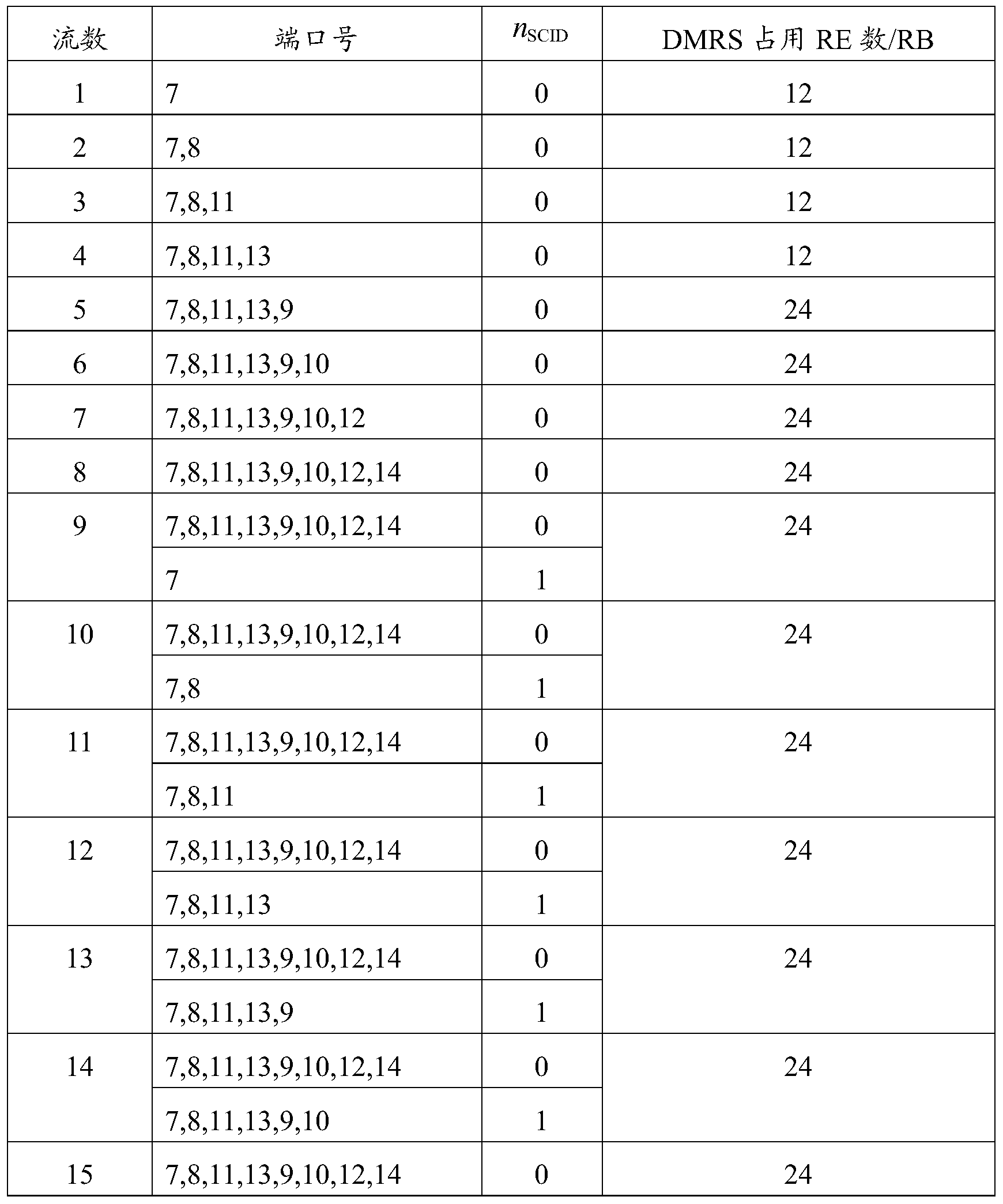
- a DMRS configuration set mapping table that supports up to 16 transport streams can be as shown in Table 2:
- the first terminal is configured with a mapping table of the correspondence between the number of transport streams and the DMRS configuration set as shown in Table 2:
- the first terminal first obtains the number of transmission data flows of all the terminals scheduled in the scheduling resource, for example, may be obtained by using the indication information of the number of transmission data flows of all terminals scheduled in the scheduling resource, and the acquisition is assumed.
- the number of the transmitted data streams of all the terminals that are scheduled in the scheduled resource is 10, and the first terminal queries the number of the transmitted data streams configured on the terminal according to the number of transmitted data streams (10) of all the terminals scheduled in the scheduled resource.
- a mapping table (Table 2) corresponding to the DMRS configuration set, the DMRS configuration set corresponding to the number of transmitted data streams (10) can be obtained as ⁇ (7, 0), (8, 0), (11, 0), ( 13,0), (9,0), (10,0), (12,0), (14,0), (7,1), (8,1) ⁇ , where the elements in the set (a, b) represents a set of port numbers and scrambling code identifiers, where a represents the port number and b represents the scrambling code identifier, such as n SCID ;
- the first terminal learns the DMRS configuration corresponding to its own transmission data stream by using its own DCI, and assumes that the DMRS corresponding to the transmission data stream of the first terminal is configured as ⁇ (11, 0), (13, 0) ⁇ , and the number of data streams. Is 2;
- the first terminal according to the obtained DMRS configuration set is ⁇ (7, 0), (8, 0), (11, 0), (13, 0), (9, 0), (10, 0), (12 , 0), (14, 0), (7, 1), (8, 1) ⁇ and its corresponding DMRS configuration is ⁇ (11, 0), (13, 0) ⁇ , which can be determined in the scheduling resource
- the DMRS corresponding to the interference data stream of the first terminal is configured as ⁇ (7, 0), (8, 0), (9, 0), (10, 0), (12, 0), (14, 0) , (7,1), (8,1) ⁇ .
- the first terminal may further determine, according to the obtained quantity of the transmission data flow of all the terminals scheduled in the at least one scheduling resource, the interference data stream corresponding to the first terminal in the scheduling resource.
- the RE location occupied by the DMRS Specifically, after the first terminal acquires the transmission data flow quantity indication information of all the terminals scheduled in the at least one scheduling resource, the first terminal may first obtain the correspondence between the number of the transmission data flows and the DMRS configuration set; Obtaining a DMRS configuration set corresponding to the number of transmission data flows of all terminals scheduled in the scheduling resource, and determining the DMRS configuration set according to the obtained DMRS configuration set.
- the RE location occupied by the DMRS corresponding to the interference data stream of the first terminal in the scheduling resource For example, based on Table 2, the correspondence between the number of simplified transport streams and the DMRS configuration set can be as shown in Table 3:
- Table 3 shows an example of the correspondence between the number of simplified transport streams and the DMRS configuration set (a DMRS configuration set supporting up to 16 transport streams)
- the first terminal may obtain a DMRS configuration set corresponding to the number of transmission data flows of all terminals scheduled in the scheduling resource according to the number of transmission data flows of all terminals scheduled in the scheduling resource (assumed to be 10). (The number of DMRSs in an RB is 24). Finally, according to the obtained DMRS configuration set (that is, the number of DMRSs in an RB is 24), the DMRS corresponding to the interference data stream of the first terminal in the scheduling resource may be determined.
- the occupied RE location for example, for the DMRS pattern as shown in FIG. 2, the RE position that the DMRS corresponding to the interference data stream may occupy is a group of the same RE multiplexed by the ports 7, 8, 11, 13 and for the ports 9, 10, 12, 14 multiplexed another group of the same RE).
- any scheduled terminal (first terminal) in a scheduling resource for any scheduled terminal (first terminal) in a scheduling resource, the number of transmission data streams of all terminals currently scheduled, and the transmission data of all terminals currently scheduled are obtained.
- a DMRS configuration set of the number of flows, a DMRS configuration corresponding to the transport data stream of the first terminal itself, and a DMRS configuration corresponding to the interference data stream of the first terminal obtained according to the foregoing information.
- any one of the scheduled terminals (the first terminal) can estimate the interference data according to the DMRS configuration corresponding to the interference data stream, in addition to the channel for estimating the transmission data stream of the DMRS configuration corresponding to the transmission data stream. The channel of the stream.
- the first terminal acquires the RE quantity indication information occupied by the DMRS corresponding to the transmission data stream of all the terminals scheduled to be scheduled in the at least one scheduling resource; in step 302, the first terminal is configured according to the acquired at least one scheduling resource.
- the RE number indication information occupied by the DMRS corresponding to the transmission data stream of all the terminals in the scheduled resource, and the RE position occupied by the DMRS corresponding to the interference data stream of the first terminal in the scheduling resource is determined.
- the RE number indication information occupied by the DMRS corresponding to the transport data stream of all the terminals scheduled in the scheduling resource may be the transmission data of all the terminals scheduled in the scheduling resource.
- the number of REs occupied by the DMRS of the stream in a specific time-frequency resource indicates information, and the specific time-frequency resource may include one or more PRBs in the scheduling resource.
- the number of REs occupied by the DMRS corresponding to the transmission data stream of all terminals in one scheduling resource is hereinafter, and one DMRS corresponding to the transmission data stream of all terminals scheduled in one scheduling resource is a PRB in the scheduling resource.
- the number of REs occupied by the above is taken as an example. It should be understood that, for a scheduling resource, each DMRS corresponding to the transmission data stream of all terminals scheduled in the scheduling resource is included in the scheduling resource.
- the number of REs occupied in one PRB is the same, and the number of PRBs included in one scheduling resource depends on the bandwidth.
- the DMRS pattern shown in Figure 2 on 12 REs in a resource block (PRB), ports 7, 8, 11, 13 multiplex a group of identical REs, distinguished by OCC; in a resource block (PRB) On the other 12 REs, the ports 9, 10, 12, and 14 are multiplexed with another group of the same RE, and are distinguished by the OCC. Therefore, for one scheduling resource, the DMRS corresponding to the transmission data stream of all the terminals scheduled in the scheduling resource.
- the number of REs occupied in one PRB can reflect the RE positions occupied by the DMRS corresponding to the transport data streams of all terminals scheduled in the scheduling resource in the PRB, and further, due to all the terminals scheduled in one scheduling resource
- the DMRS corresponding to the transport data stream has the same number of REs occupied in each PRB included in the scheduling resource, and thus the RE position occupied by the DMRS corresponding to the transport data stream of all the scheduled terminals in the scheduled resource may be determined. Taking the DMRS pattern as shown in FIG.
- the number of REs occupied by the DMRS port when the number of REs occupied by the DMRS port is 12, it corresponds to the RE position occupied by one or more of port 7, port 8, port 11, and port 13 or Corresponding to the RE position occupied by one or more of port 9, port 10, port 12, and port 14; the number of REs occupied by the DMRS port is 24 hours, corresponding to port 7, port 8, port 11, and port One or more of 13 and the RE location occupied by one or more of port 9, port 10, port 12, and port 14.
- the number of RE indication information occupied by the DMRS corresponding to all the scheduled ones in the one or more scheduling resources may be sent by using DCI or RRC signaling.
- the indication information can be a DCI within a common search space.
- the indication information of the number of REs occupied by the DMRSs corresponding to all the scheduled terminals in the at least one scheduling resource sent by the base station may be the same as that of all the terminals scheduled in the at least one scheduling resource sent by the base station described in the first scheme.
- the indication information of the number of transmitted data streams is similar, and the indication information of the number of REs occupied by the DMRSs corresponding to all the terminals scheduled in the multiple scheduling resources may also be in one scheduling resource, and the multiple coding resources are respectively indicated by means of joint coding. Corresponding information about the number of REs occupied by the DMRS corresponding to all the terminals scheduled.
- the number of REs occupied by the DMRSs corresponding to all the scheduled terminals may be indicated by a number of bits in the DCI or the RRC signaling of the common search space, and may be all possible according to the number of occupied REs.
- the allocation bit (for example, at least 1 bit is allocated for occupying 12RE or 24RE in one PRB).
- the signaling design for all terminals scheduled in a scheduling resource may include (set the scheduling resource)
- the number of REs occupied by a DMRS corresponding to all terminals in a PRB is M): the number of REs occupied by a DMRS corresponding to all terminals in the scheduled resource within one PRB, for example, may be used by all terminals.
- the first terminal may be configured according to all the terminals scheduled in the acquired at least one scheduling resource.
- the RE number indication information occupied by the DMRS corresponding to the transmission data stream determining the RE location occupied by the DMRS corresponding to the transmission data stream of all the terminals scheduled to be scheduled in the scheduling resource; and the transmission data of all the terminals scheduled in the scheduling resource according to the scheduling resource.
- the RE location occupied by the DMRS corresponding to the flow is determined, and the RE location occupied by the DMRS corresponding to the interference data flow of the first terminal in the scheduling resource is determined, and the RE location occupied by the DMRS corresponding to the determined interference data flow is located in all the scheduled terminals.
- the transmission data stream corresponds to the RE location occupied by the DMRS.
- the number of REs occupied by the DMRS corresponding to the transmitted data stream of all the scheduled terminals in one RB may be 12 or 24, based on FIG. 2
- the DMRS pattern shown, wherein, when the value is 12, the RE position occupied by the DMRS corresponding to the transmission data stream of all the scheduled terminals may be the ports 7, 8, 11, and 13 in the DMRS pattern shown in FIG.
- the RE location occupied by the DMRS may be a group of identical REs multiplexed by ports 7, 8, 11, and 13 in the DMRS pattern shown in FIG. 2 and another group of identical REs multiplexed by ports 9, 10, 12, and 14. Specifically, it can be as shown in Table 4.
- the base station when the DMRS is configured for the terminal, the base station first allocates port 7, port 8, port 11, and port 13. When the data stream to be transmitted needs to be increased, the port needs to be added. Increasing the use of one or more of port 9, port 10, port 12, port 14 is therefore more common in scenario 1 and scenario 3 shown in Table 4, while scenario 2 may not occur under existing protocols.
- Table 4 The number of REs occupied and the possible situation of occupied RE positions
- the RE location occupied by the DMRS corresponding to the transmission data stream of all the terminals further determines the DMRS configuration corresponding to the interference data flow of the first terminal in the scheduling resource.
- the number of REs occupied by the DMRS corresponding to the transmission data stream of all terminals currently scheduled in the scheduling resource can be known.
- the first terminal may further configure, according to the determined DMRS corresponding to the interference data stream of the first terminal, or the occupied RE. Position, performing interference covariance matrix estimation on the interference data stream of the first terminal.
- the IRC receiver adopting the interference suppression algorithm can perform the interference covariance matrix estimation on the interference data stream of the first terminal according to the determined DMRS configuration or the occupied RE position corresponding to the interference data stream of the first terminal, which can improve The accuracy of the interference estimation, the detection performance of the receiver is enhanced, and the reception quality of the signal is improved, especially in the case of multi-stream transmission, the user reception performance can be significantly improved.
- a DMRS indication method may be implemented by a base station: the base station sends, to the first terminal, the indication quantity of the transmission data stream of all the terminals scheduled in the at least one scheduling resource, or all the scheduled resources in the at least one scheduling resource. And indicating, by the first terminal, any one of the scheduled terminals, where the indication information is used by the first terminal to determine a scheduling resource. Corresponding to the interference data stream of the first terminal DMRS configuration or occupied RE location.
- the first terminal first acquires the transmission data flow quantity indication information of all the terminals scheduled in the at least one scheduling resource or all the scheduled resources in the at least one scheduling resource. Determining the number of REs occupied by the DMRS corresponding to the transmission data stream of the terminal, where the first terminal is one of the terminals that are scheduled, and the first terminal determines, according to the indication information, the first terminal in the scheduling resource.
- the interference data stream corresponds to the DMRS configuration or the occupied RE location.
- the DMRS indication method provided in the embodiment of the present invention enables the terminal to determine the DMRS configuration or the occupied RE location corresponding to the interference data flow of the terminal in the scheduling resource.
- the DMRS resource indication method provided in the embodiment of the present invention can also enable the terminal to determine the DMRS configuration or occupation corresponding to the interference data flow, in which the terminal can only obtain the DMRS allocation corresponding to the transmission data stream of the terminal itself.
- the RE position provides a basis for estimating the interference covariance matrix, thereby improving the accuracy of the channel estimation, especially for the case of multi-stream transmission, which can achieve better channel estimation effect, thereby ensuring the terminal side receiver. Detection performance and overall system performance.
- the embodiment of the present invention further provides a terminal, which can perform the foregoing DMRS indication method embodiment described on the terminal side.
- the terminal provided by the embodiment of the present invention may include: an obtaining module 401 and a determining module 402.
- the term "module” may be a combination of software and/or hardware that implements a predetermined function.
- the structure of the terminal provided by the embodiment of the present invention is described in detail below:
- the determining module 402 is configured to determine, according to the obtained indication information, a DMRS configuration or an occupied RE location corresponding to the interference data flow of the local terminal in the scheduling resource.
- the determining module 402 is specifically configured to:
- the corresponding relationship between the number of the transmitted data streams and the DMRS configuration set is configured by the base station to the local terminal, or the corresponding relationship between the number of the transmitted data streams and the DMRS configuration set is pre-agreed by the base station and the local terminal.
- the determining module 402 is specifically configured to:
- the occupied RE location is located within the RE location occupied by the DMRS corresponding to the transmission data stream of all scheduled terminals.
- the indication information is sent by using the following signaling: downlink control information DCI or high layer radio resource control RRC signaling.
- the downlink control information DCI is a DCI in a common search space.
- the embodiment of the present invention further provides a base station, which can perform the foregoing DMRS resource indication method embodiment described on the base station side.
- the base station according to the embodiment of the present invention may include: a sending module 501, configured to send, to the first terminal, the quantity of the transmitted data stream of all the terminals scheduled in the at least one scheduling resource, or the at least one scheduling resource.
- the DMRS configuration or the occupied RE location corresponding to the interference data stream of the first terminal in the scheduling resource is determined.
- module may be a combination of software and/or hardware that implements a predetermined function.
- the structure of the base station provided by the embodiment of the present invention is described in detail below.
- the sending module 501 is configured to send DCI or RRC signaling to the first terminal, where the DCI or RRC signaling is used to indicate transmission data of all terminals scheduled in the at least one scheduling resource of the first terminal.
- the base station provided by the embodiment of the present invention may further include: a configuration module 502, configured to configure, by using the correspondence between the number of the transmitted data streams and the DMRS configuration set, to the first terminal, where the value of the number of the transmitted data streams is unique Corresponding to a DMRS configuration set; or pre-arranging a correspondence between the number of transport data streams and the DMRS configuration set with the first terminal.
- a configuration module 502 configured to configure, by using the correspondence between the number of the transmitted data streams and the DMRS configuration set, to the first terminal, where the value of the number of the transmitted data streams is unique Corresponding to a DMRS configuration set; or pre-arranging a correspondence between the number of transport data streams and the DMRS configuration set with the first terminal.
- an embodiment of the present invention further provides a terminal, which can implement the foregoing The flow of the DMRS indication method implemented on the terminal side described in the embodiment.
- FIG. 6 is a schematic structural diagram of a terminal according to an embodiment of the present invention.
- the terminal may include: a processor 601, a memory 602, a transceiver 603, and a bus interface.
- the processor 601 is responsible for managing the bus architecture and general processing, and the memory 602 can store data used by the processor 601 in performing operations.
- the transceiver 603 is configured to receive and transmit data under the control of the processor 601.
- the bus architecture may include any number of interconnected buses and bridges, specifically linked by one or more processors represented by processor 601 and various circuits of memory represented by memory 602.
- the bus architecture can also link various other circuits such as peripherals, voltage regulators, and power management circuits, which are well known in the art and, therefore, will not be further described herein.
- the bus interface provides an interface.
- Transceiver 603 can be a plurality of components, including a transmitter and a transceiver, providing means for communicating with various other devices on a transmission medium.
- the processor 601 is responsible for managing the bus architecture and general processing, and the memory 602 can store data used by the processor 601 in performing operations.
- the flow of the DMRS indication method on the terminal side disclosed in the embodiment of the present invention may be applied to the processor 601 or implemented by the processor 601.
- each step of the flow of the DMRS indication method may be completed by an integrated logic circuit of hardware in the processor 601 or an instruction in a form of software.
- the processor 601 can be a general purpose processor, a digital signal processor, an application specific integrated circuit, a field programmable gate array or other programmable logic device, a discrete gate or transistor logic device, a discrete hardware component, and can implement or perform the embodiments of the present invention.
- a general purpose processor can be a microprocessor or any conventional processor or the like.
- the steps of the method disclosed in the embodiments of the present invention may be directly implemented as a hardware processor, or may be performed by a combination of hardware and software modules in the processor.
- the software module can be located in a conventional storage medium such as random access memory, flash memory, read only memory, programmable read only memory or electrically erasable programmable memory, registers, and the like.
- the storage medium is located in the memory 602, and the processor 601 reads the information in the memory 602 and completes the steps of the DMRS indication process in conjunction with its hardware.
- the processor 601 is configured to read a program in the memory 602, and the following process can be performed:
- the indication information that is obtained determines the DMRS configuration or the occupied RE location corresponding to the interference data flow of the local terminal in the scheduling resource.
- the processor 601 may be configured to: obtain, from the memory 602, a correspondence between the number of transport data streams and the DMRS configuration set, where the value of the number of transport data flows uniquely corresponds to a DMRS configuration set; A quantity of transmission data stream indication information of all terminals scheduled in a scheduling resource, and a correspondence between the number of the transmission data streams and a DMRS configuration set, and acquiring a DMRS corresponding to the number of transmission data streams of all terminals scheduled in the scheduling resource.
- the DMRS configuration corresponding to the interference data flow of the local terminal in the scheduling resource is determined according to the obtained DMRS configuration set and the DMRS configuration corresponding to the transmission data flow of the local terminal.
- the processor 601 may be configured to: determine, according to the RE number indication information occupied by the DMRS corresponding to the transport data stream of all the terminals scheduled to be scheduled in the at least one scheduled resource, the transmission data of all the terminals scheduled in the scheduling resource. And determining, according to the RE location occupied by the DMRS corresponding to the transmission data stream of all the terminals scheduled to be in the scheduling resource, determining the RE position occupied by the DMRS corresponding to the interference data flow of the terminal in the scheduling resource, The RE location occupied by the DMRS corresponding to the determined interference data stream is located within the RE location occupied by the DMRS corresponding to the transmission data stream of all scheduled terminals.
- an embodiment of the present invention further provides a base station, which can implement the flow of the DMRS indication method implemented on the base station side described in the foregoing embodiment.
- FIG. 7 is a schematic structural diagram of a base station according to an embodiment of the present invention.
- the base station may include: a processor 701, a memory 702, a transceiver 703, and a bus interface.
- the processor 701 is responsible for managing the bus architecture and general processing, and the memory 702 can store data used by the processor 701 in performing operations.
- the transceiver 703 is configured to receive and transmit data under the control of the processor 701.
- the flow of the DMRS indication method on the base station side disclosed in the embodiment of the present invention may be applied to the processor 701 or implemented by the processor 701.
- each step of the flow of the DMRS indication method may be completed by an integrated logic circuit of hardware in the processor 701 or an instruction in the form of software.
- the processor 701 can be a general purpose processor, a digital signal processor, an application specific integrated circuit, a field programmable gate array or other programmable logic device, a discrete gate or transistor logic device, a discrete hardware component, and can implement or perform the embodiments of the present invention.
- a general purpose processor can be a microprocessor or any conventional processor or the like.
- the steps of the method disclosed in the embodiments of the present invention may be directly implemented as a hardware processor, or may be performed by a combination of hardware and software modules in the processor.
- the software module can be located in a conventional storage medium such as random access memory, flash memory, read only memory, programmable read only memory or electrically erasable programmable memory, registers, and the like.
- the storage medium is located in the memory 702, and the processor 701 reads the information in the memory 702 and completes the steps of the DMRS indication process in conjunction with its hardware.
- the processor 701 is configured to read a program in the memory 702 and control the transceiver 703 to perform corresponding operations.
- the transceiver 703 can perform the following processes:
- the first terminal is any one of the scheduled terminals, and the indication information is used by the first terminal to determine a DMRS configuration or an occupied RE corresponding to the interference data flow of the first terminal in the scheduling resource. position.
- the transceiver 703 may notify the first terminal by transmitting DCI or RRC signaling to notify the first terminal of the number of transmission data flow indication information of all terminals scheduled in at least one scheduling resource or at least one scheduling resource.
- the processor 701 is configured to read a program in the memory 702, and may also perform the following processes:
- embodiments of the present invention can be provided as a method, system, or computer program product. Accordingly, the present invention may take the form of an entirely hardware embodiment, an entirely software embodiment, or a combination of software and hardware. Moreover, the invention can take the form of a computer program product embodied on one or more computer-usable storage media (including but not limited to disk storage, CD-ROM, optical storage, etc.) including computer usable program code.
- computer-usable storage media including but not limited to disk storage, CD-ROM, optical storage, etc.
- the computer program instructions can also be stored in a computer readable memory that can direct a computer or other programmable data processing device to operate in a particular manner, such that the instructions stored in the computer readable memory produce an article of manufacture comprising the instruction device.
- the apparatus implements the functions specified in one or more blocks of a flow or a flow and/or block diagram of the flowchart.
- These computer program instructions can also be loaded onto a computer or other programmable data processing device such that a series of operational steps are performed on a computer or other programmable device to produce computer-implemented processing for execution on a computer or other programmable device.
- the instructions provide steps for implementing the functions specified in one or more of the flow or in a block or blocks of a flow diagram.
Landscapes
- Engineering & Computer Science (AREA)
- Signal Processing (AREA)
- Computer Networks & Wireless Communication (AREA)
- Quality & Reliability (AREA)
- Power Engineering (AREA)
- Mobile Radio Communication Systems (AREA)
Abstract
本发明公开了解调参考信号DMRS指示方法、终端及基站。本发明方法包括:第一终端获取至少一个调度资源内被调度的所有终端的传输数据流数量指示信息,或至少一个调度资源内被调度的所有终端的传输数据流对应的DMRS所占用的资源单元RE数量指示信息;第一终端根据获取到的指示信息,确定调度资源内所述第一终端的干扰数据流对应的DMRS配置或占用的RE位置。本发明能够指示多数据流传输时的DMRS,尤其适用于大规模天线阵列的MU-MIMO系统。
Description
本申请要求在2015年12月9日提交中国专利局、申请号为201510907474.9、发明名称为“一种DMRS指示方法、终端及基站”的中国专利申请的优先权,其全部内容通过引用结合在本申请中。
本发明涉及通信技术领域,尤其涉及一种DMRS指示方法、终端及基站。
随着通信技术的发展以及通信网络对速率和容量需求的增加,在LTE(Long Term Evolution,长期演进)系统中,采用多天线MIMO(Multiple-Input Multiple-Output,多输入多输出)技术以更好地利用空间维度资源,提高频谱效率,使信号在空间域获得阵列增益、分集增益、复用增益和干扰抵消增益等。而随着终端数量的飞速增长,MU-MIMO(Multi-User Multiple-Input Multiple-Output,多用户多输入多输出)技术使得基站能够与多个终端同时利用相同的时频资源进行上行、下行数据传输,从而能够进一步地获得多用户分集增益以及空间复用增益等,提升系统容量。
终端根据参考信号估计每个发射天线的信道来恢复从每个发射天线发送的数据,参考信号也可以被称为导频信号。在LTE系统中,终端可以通过DMRS(DeModulation Reference Signal,解调参考信号)进行信道估计用于数据解调。针对一个终端,基站向该终端传送的DMRS采用了与向该终端发送的数据相同的预编码操作,该终端通过对DMRS的测量就可以获知预编码后的等效信道矩阵。对于大规模天线阵列的MU-MIMO系统,同时进行传输的数据流数大幅提高,系统性能的维系将越来越依赖于信道估计的准确性。
因此,对于多数据流传输时的用于信道估计的DMRS的指示方法,是业界所亟待深入研究的技术问题。
发明内容
本发明实施例提供一种DMRS指示方法、终端及基站,用以指示多数据流传输时的DMRS。
本发明的一个实施例提供的DMRS指示方法,包括:
第一终端获取至少一个调度资源内被调度的所有终端的传输数据流数量指示信息,或至少一个调度资源内被调度的所有终端的传输数据流对应的DMRS所占用的资源单元RE
数量指示信息,所述第一终端为所述被调度的所有终端中的任一终端;
所述第一终端根据获取到的指示信息,确定调度资源内所述第一终端的干扰数据流对应的DMRS配置或占用的RE位置。
可选地,所述第一终端根据获取到的至少一个调度资源内被调度的所有终端的传输数据流数量指示信息,确定调度资源内所述第一终端的干扰数据流对应的DMRS配置,包括:
所述第一终端获取传输数据流数量与DMRS配置集合的对应关系,其中,传输数据流数量的一种取值唯一对应于一个DMRS配置集合;
所述第一终端根据获取到的至少一个调度资源内被调度的所有终端的传输数据流数量指示信息,以及所述传输数据流数量与DMRS配置集合的对应关系,获取与调度资源内被调度的所有终端的传输数据流数量对应的DMRS配置集合;
所述第一终端根据获取到的DMRS配置集合,以及所述第一终端的传输数据流对应的DMRS配置,确定调度资源内所述第一终端的干扰数据流对应的DMRS配置。
其中,所述传输数据流数量与DMRS配置集合的对应关系为所述基站配置给所述第一终端的;或者所述传输数据流数量与DMRS配置集合的对应关系为所述基站与所述第一终端预先约定的。
可选地,所述第一终端根据获取到的至少一个调度资源内被调度的所有终端的传输数据流对应的DMRS所占用的资源单元RE指示信息,确定调度资源内所述第一终端的干扰数据流对应的DMRS占用的RE位置,包括:
所述第一终端根据获取到的至少一个调度资源内被调度的所有终端的传输数据流对应的DMRS所占用的RE数量指示信息,确定调度资源内被调度的所有终端的传输数据流对应的DMRS占用的RE位置;
所述第一终端根据所述调度资源内被调度的所有终端的传输数据流对应的DMRS占用的RE位置,确定调度资源内所述第一终端的干扰数据流对应的DMRS占用的RE位置,所确定的干扰数据流对应的DMRS占用的RE位置位于所述被调度的所有终端的传输数据流对应的DMRS占用的RE位置之内。
其中,所述指示信息通过以下信令发送:下行控制信息DCI或高层无线资源控制RRC信令。
优选地,所述下行控制信息DCI为公共搜索空间内的DCI。
本发明的一个实施例提供的DMRS指示方法,包括:
基站向第一终端发送至少一个调度资源内被调度的所有终端的传输数据流数量指示信息,或至少一个调度资源内被调度的所有终端的传输数据流对应的DMRS所占用的RE数量指示信息,所述第一终端为所述被调度的所有终端中的任一终端,所述指示信息被所述第一终端用于确定调度资源内所述第一终端的干扰数据流对应的DMRS配置或占用的
RE位置。
可选地,所述基站通过向所述第一终端发送DCI或RRC信令,所述DCI或RRC信令用于指示所述第一终端至少一个调度资源内被调度的所有终端的传输数据流数量,或至少一个调度资源内被调度的所有终端的传输数据流对应的DMRS所占用的RE数量。
优选地,本发明的一个实施例提供的DMRS指示方法还包括:所述基站将传输数据流数量与DMRS配置集合的对应关系配置给所述第一终端,其中,传输数据流数量的一种取值唯一对应于一个DMRS配置集合;或者所述基站与所述第一终端预先约定传输数据流数量与DMRS配置集合的对应关系。
本发明的一个实施例提供的一种终端,包括:
获取模块,用于获取至少一个调度资源内被调度的所有终端的传输数据流数量指示信息,或至少一个调度资源内被调度的所有终端的传输数据流对应的DMRS所占用的资源单元RE数量指示信息;
确定模块,用于根据获取到的指示信息,确定调度资源内本终端的干扰数据流对应的DMRS配置或占用的RE位置。
所述确定模块,可以具体用于:
获取传输数据流数量与DMRS配置集合的对应关系,其中,传输数据流数量的一种取值唯一对应于一个DMRS配置集合;
根据获取到的至少一个调度资源内被调度的所有终端的传输数据流数量指示信息,以及所述传输数据流数量与DMRS配置集合的对应关系,获取与调度资源内被调度的所有终端的传输数据流数量对应的DMRS配置集合;
根据获取到的DMRS配置集合以及本终端的传输数据流对应的DMRS配置,确定调度资源内本终端的干扰数据流对应的DMRS配置。
其中,所述传输数据流数量与DMRS配置集合的对应关系为所述基站配置给本终端的;或者所述传输数据流数量与DMRS配置集合的对应关系为所述基站与本终端预先约定的。
所述确定模块,可以具体用于:
根据获取到的至少一个调度资源内被调度的所有终端的传输数据流对应的DMRS所占用的RE数量指示信息,确定调度资源内被调度的所有终端的传输数据流对应的DMRS占用的RE位置;
根据所述调度资源内被调度的所有终端的传输数据流对应的DMRS占用的RE位置,确定调度资源内本终端的干扰数据流对应的DMRS占用的RE位置,所确定的干扰数据流对应的DMRS占用的RE位置位于所述被调度的所有终端的传输数据流对应的DMRS占用的RE位置之内。
其中,所述指示信息通过以下信令发送:下行控制信息DCI或高层无线资源控制RRC信令。
优选地,所述下行控制信息DCI为公共搜索空间内的DCI。
本发明的一个实施例提供的一种基站,包括:
发送模块,用于向第一终端发送至少一个调度资源内被调度的所有终端的传输数据流数量指示信息或至少一个调度资源内被调度的所有终端的传输数据流对应的DMRS所占用的RE数量指示信息,所述第一终端为所述被调度的所有终端中的任一终端,所述指示信息被所述第一终端用于确定调度资源内所述第一终端的干扰数据流对应的DMRS配置或占用的RE位置。
可选地,所述发送模块通过向所述第一终端发送DCI或RRC信令,所述DCI或RRC信令用于指示所述第一终端至少一个调度资源内被调度的所有终端的传输数据流数量的指示信息,或至少一个调度资源内被调度的所有终端的传输数据流对应的DMRS所占用的RE数量的指示信息。
优选地,本发明的一个实施例提供的一种基站,还包括:配置模块,用与将传输数据流数量与DMRS配置集合的对应关系配置给所述第一终端,其中,传输数据流数量的一种取值唯一对应于一个DMRS配置集合;或者与所述第一终端预先约定传输数据流数量与DMRS配置集合的对应关系。
在本发明实施例中提供的DMRS指示方法中,第一终端首先获取至少一个调度资源内被调度的所有终端的传输数据流数量指示信息,或至少一个调度资源内被调度的所有终端的传输数据流对应的DMRS所占用的RE数量指示信息,所述第一终端为所述被调度的所有终端中的任一终端,再根据上述指示信息,确定调度资源内所述第一终端的干扰数据流对应的DMRS配置或占用的RE位置。可以看到,本发明实施例中提供的DMRS指示方法能够使终端确定出调度资源内该终端的干扰数据流对应的DMRS配置或占用的RE位置。较现有技术中终端只能获取该终端自身传输数据流所对应的DMRS分配的情况,本发明实施例中提供的DMRS资源指示方法还能够使终端确定出干扰数据流对应的DMRS配置或占用的RE位置,从而为进行干扰协方差矩阵估计提供依据,进而提高信道估计的准确性,保证整体系统性能。
为了更清楚地说明本发明实施例中的技术方案,下面将对实施例描述中所需要使用的附图作简要介绍,显而易见地,下面描述中的附图仅仅是本发明的一些实施例,对于本领域的普通技术人员来讲,在不付出创造性劳动性的前提下,还可以根据这些附图获得其他的附图。
图1为现有技术中LTE网络系统的结构示意图;
图2为现有技术中一种正常CP情况下的DMRS图样示意图;
图3为本发明的一个实施例提供的DMRS指示方法的流程示意图;
图4为本发明的一个实施例提供的一种终端的结构示意图;
图5为本发明的一个实施例提供的一种基站的结构示意图;
图6为本发明的一个实施例提供的一种终端的结构示意图;
图7为本发明的一个实施例提供的一种基站的结构示意图。
为了使本发明的目的、技术方案和优点更加清楚,下面将结合附图对本发明作进一步地详细描述,显然,所描述的实施例仅仅是本发明一部份实施例,而不是全部的实施例。基于本发明中的实施例,本领域普通技术人员在没有做出创造性劳动前提下所获得的所有其它实施例,都属于本发明保护的范围。
随着通信系统的发展,MIMO技术成为LTE网络系统中的关键技术之一,MIMO系统通过使用多个发射天线和多个接收天线而增加系统容量,提升吞吐率。MIMO技术包括有空间复用(SDM,Spatial division multiplexing)、空间分集(Spatial diversity)和波形赋形(BF,Beamforming)等技术。引入MIMO的LTE网络系统根据终端的空间特性又可以分为单用户MIMO(SU-MIMO)系统和多用户MIMO(MU-MIMO)系统。根据下行MU-MIMO操作,两个或更多个终端在一个基站下发的特定PRB(Physical Resource Block,物理资源块)上接收下行链路信号。
一个下行MU-MIMO信道系统包括有发射端(比如基站)和接收端(比如终端),均有多根天线。其中,发射端可以有一个或多个,接收端一般为多个。图1示出了应用MU-MIMO技术的LTE网络中一个基站与多个终端的情景。对于LTE的下行MIMO传输过程,基站根据每个终端的信道条件、业务特点及优先级等因素进行调度并为每一个被调度的终端分配一定数量的原始比特流,将分配给每个终端的原始比特流通过调制、信道编码后转换为一路或多路并行的传输数据流(或LTE中的传输数据层),每路传输数据流对应一个DMRS(DeModulation Reference Signal,解调参考信号)端口。多路传输数据流再经过预编码进行加权、资源映射转换成对应多个发射天线的多路发送信号,通过不同的发射天线发送出去。每一个终端利用不少于本终端的传输数据流数的天线阵列进行接收,并利用估计出的信道状态信息对多路接收信号进行频域资源逆映射、空域与时间域上的处理,恢复出自己的传输数据流。多路传输数据流再经过并串变换、信道译码最终恢复出原始数据比特。
其中,在本发明实施例中,终端可以是具有无线通信功能的手持设备、车载设备、可
穿戴设备、计算设备或连接到无线调制解调器的其它处理设备,以及各种形式的用户设备(User Equipment,简称UE),移动台(Mobile station,简称MS),终端(terminal),终端设备(Terminal Equipment)等,本发明对此并不限定。
其中,在本发明实施例中,基站可以是LTE系统中的演进型基站(Evolutional Node B,简称为eNB或e-NodeB)、宏基站、微基站(也称为“小基站”)、微微基站、接入站点(Access Point,简称为AP)或传输站点(Transmission Point,简称为TP)以及下一代无线通信系统的基站等,基站也可以用作包括小区或扇区的概念,本发明对此并不限定。
其中,在本发明实施例中,LTE可以被认为对应于3GPP(3rd Generation Partnership Project,第三代合作伙伴)版本8(Rel-8或R8)、版本9(Rel-9或R9)、版本10(Rel-10或R10)以及版本10及以上的版本,LTE网络结构可以是宏蜂窝、微蜂窝、微微蜂窝、毫微微蜂窝,由中继器和中继转发节点组成的网络以及各种混合网络结构(可以由宏蜂窝、微蜂窝、微微蜂窝、毫微微蜂窝,以及中继器和中继转发节点中的一种或多种组成)等,本发明对此并不限定。
由于终端通过估计用于每个发射天线端口到所有接收天线的信道来恢复从每个发射天线端口对应的发送的数据,针对信道估计,需要基站和终端都知道的参考信号(也可以被称为导频信号)。下行链路参考信号是用于下行信道估计以便实现相干解调,比如PDSCH(Physical downlink shared channel,物理下行共享信道)、PCFICH(Physical control format indicator channel,物理下行控制格式指示信道)、PHICH(Physical Hybrid ARQ Indicator Channel,物理混合自动重传指示信道)以及PDCCH(Physical Downlink Control Channel,物理下行控制信道)的导频信号。下行链路参考信号的示例包括由基站覆盖范围内的终端所共享的CRS(common reference signal,公共参考信号)和仅用于特定终端的DRS(dedicated reference signal,专用参考信号)。DMRS是一种专用参考信号。针对一个终端,基站向该终端传送的DMRS采用了与向该终端发送的传输数据流相同的预编码操作,该终端通过对DMRS的测量就可以估计出预编码后的等效信道矩阵,从而进行数据解调。
在LTE系统中,基站对终端的调度基于调度资源,一个调度资源在时域上可以是一个子帧,一个调度资源在频域上可以包含若干个PRB。图2示出了一种正常CP(Cyclic Prefix,循环前缀)情况下的DMRS图样(即DMRS所映射到的RE)。参考图2,水平轴表示时域,垂直轴表示频域。可以看到,一个子帧是由14个连续的OFDM(Orthogonal Frequency Division Multiplexing,正交频分复用)符号(一个OFDM符号为1/14ms)和12个子载波(一个子载波宽度为15kHz)组成,包含两个时隙(slot),每个时隙时间长度为0.5ms。其中,时域上占7个OFDM符号、频域上占12个子载波称为一个RB(Resource Block,资源块),RB在物理层又被称为PRB。其中,图2示出的最小的正方形区域对应于时域上占1个OFDM符号以及频域上占1个子载波,称为一个RE(Resource Element,资源单元)。
时域上的每个子帧所包含的PRB数量与系统带宽有关,比如,系统带宽为20MHz时,对应100个PRB。
为了简化讨论,在下文的描述中将考虑具有正常循环前缀配置的子帧,应当理解的是,类似的构思可以应用于具有扩展循环前缀的子帧,
按照现有标准的规定,在采用TM10、TM11(Transmission Mode,传输模式)的下行SU-MIMO(Single User-MIMO,单用户MIMO)传输时基站为一个被调度的终端分配一定数量的传输数据流,每个传输数据流都对应一个DMRS端口,其中每个传输数据流又称为传输层(layer)。
为了支持最多8个传输数据流的空间复用技术,LTE Rel-10可以提供8个DMRS端口(端口7至端口14)。其中8个端口对应的传输数据流经过预编码加权处理映射到至少8个发送天线上。这些DMRS端口可以是以码分方式(如利用OCC(Orthogonal Cover Code,正交覆盖码))或频分方式正交。在下行传输过程中,基站可以通过DCI(Downlink Control Information,下行控制信息)指示DMRS配置情况,包括为终端分配的DMRS端口以及描述DMRS扰码序列的nSCID指示等。如图2所示的DMRS图样,在一个资源块内的12个RE上,端口7、8、11、13复用一组相同RE,通过OCC区分;在一个资源块内的另外12个RE上,端口9、10、12、14复用另一组相同RE,通过OCC区分。当一个终端的传输数据流数小于等于2时使用的DMRS为端口7和端口8,DMRS端口占用一个资源块内的12个RE;当一个终端的传输数据流数大于2时使用更多的DMRS端口,DMRS端口占用在一个资源块内的24个RE。终端可以根据本终端的DMRS配置,获得传输数据流对应的DMRS在下行子帧中所占用的RE位置。
为了实现透明传输并节省DMRS占用RE的开销,LTE Rel-10中的MU-MIMO传输模式仅使用端口7、端口8,即只有2个通过OCC正交的DMRS,同时可以通过准正交(通过与传输数据流相同的预编码/波束赋形以及不同的DMRS扰码序列)方式区分配置给多个传输数据流的DMRS。仅存在端口7、端口8时,OCC长度为2。在3GPP标准中对作为大规模天线的前期技术的FD-MIMO(Full Dimension-MIMO,全维-MIMO)的讨论中,为了更好地支持更多数量的用户提出了DMRS的扩展方式,例如使用端口7、8、11、13,OCC长度为4,从而通过OCC正交的DMRS的数量扩展至4。
在PDCCH中进行下行调度时,基站可以在相应的DCI中采用3个比特联合指示终端当前的传输数据流数量,所使用的DMRS端口以及所用的SCID,例如,表1示出了基站下发的天线端口、扰码标识和数据流数指示表,3比特取值和其对应的DMRS配置内容,其中,Value标识3比特DCI取值,layer为传输数据流,Codeword为信道编码码字,分为单码字(0)和双码字(0、1)。FD-MIMO新增了DMRS的扩展,天线端口、扰码标识和数据流数指示表也进行了相应扩展。
表1 LTE Rel-10的天线端口、扰码标识和数据流数指示

可以看到,在现有技术中,基站针对一个被调度的终端,根据为该终端分配的传输数据流,在下行传输时将同时指示该终端的传输数据流对应的DMRS分配情况,包括为终端分配的DMRS端口以及描述DMRS扰码序列的nSCID指示等,以使得该终端可以正确地进行DMRS信道估计。然而对于被调度的终端以及传输数据流数量大幅增加的系统,传输数据流之间的干扰成为通信系统性能提高的一大瓶颈,信道估计成为维系系统性能的重要因素,比如对于多数据流传输时所存在的干扰,干扰协方差矩阵估计不准确时将会导致使用干扰抑制算法的IRC(Interference Rejection Combining,干扰抑制合并)接收机检测性能较差。现有技术中对于一个终端仅指示该终端的传输数据流所对应的DMRS配置的情况,不能使该终端同时完整地获得其它与该终端的传输数据流同时传输的数据流所对应的DMRS的相关信息。对于具有大规模天线的MU-MIMO系统,由于其中同时进行传输的数据流数大幅的提高,虽然大规模天线本身能够提供较强的干扰抑制能力,但是由于同时调度的传输数据流数远远多于现有LTE系统,终端仅获取该终端的传输数据流所对应的DMRS分配的情况往往不能得到很准确的信道估计,导致终端侧接收机检测性能较差,影响了整体系统性能。
针对多数据流传输的DMRS指示,本发明实施例提出一种DMRS指示方法、终端及基站,本发明实施例尤其适用于大规模天线阵列的MU-MIMO系统。下面结合附图对本发明实施例进行详细描述。
图3示出了本发明实施例提供的DMRS指示方法的流程示意图,该流程可由终端实现,其中,为了更清楚的说明本发明实施例所提供的方法,在本文的描述中使用了“第一终端”用以指示被调度的所有终端中的一个终端。该流程包括如下步骤:
步骤301:第一终端获取至少一个调度资源内被调度的所有终端的传输数据流数量指示信息,或至少一个调度资源内被调度的所有终端的传输数据流对应的DMRS所占用的资源单元RE数量指示信息,所述第一终端为所述被调度的所有终端中的任一终端。
步骤302:第一终端根据步骤301中获取到的指示信息,确定调度资源内所述第一终端的干扰数据流对应的DMRS配置或占用的RE位置。
以将上述流程应用于大规模天线阵列的MU-MIMO系统为例,步骤301中,第一终端获取至少一个调度资源内被调度的所有终端(通常为2个或2个以上终端)的传输数据流数量指示信息或至少一个调度资源内被调度的所有终端(通常为2个或2个以上终端)的传输数据流对应的DMRS所占用的RE数量指示信息。
对于一个调度资源,第一终端可以根据获取到的指示信息,获取该调度资源内被调度的所有终端的传输数据流数量;或者对于一个调度资源,第一终端可以根据指示信息,获取该调度资源内被调度的所有终端的传输数据流对应的DMRS所占用的RE数量指示信息。
其中,对于一个调度资源,该调度资源内被调度的所有终端的传输数据流对应的DMRS所占用的RE数量指示信息可以是该调度资源内被调度的所有终端的传输数据流对应的DMRS在特定时频资源内所占用的RE数量指示信息,该特定时频资源可以包含该调度资源中的一个或多个PRB。
优选地,对于一个调度资源,该调度资源内被调度的所有终端的传输数据流对应的DMRS所占用的RE数量指示信息可以是该调度资源内被调度的所有终端的传输数据流对应的DMRS在该调度资源中的一个PRB内所占用的RE数量指示信息。
具体地,对于如图3所示的包含有步骤301与步骤302的DMRS指示方法的流程,可以采用但不限于以下方案实现:
方案1
在步骤301中,第一终端获取至少一个调度资源内被调度的所有终端的传输数据流数量指示信息;在步骤302中,第一终端根据获取到的至少一个调度资源内被调度的所有终端的传输数据流数量指示信息,确定调度资源内所述第一终端的干扰数据流对应的DMRS配置。
其中,基站根据每个被调度的终端的信道条件、业务特点及优先级等因素进行调度并为每个被调度的终端分配了一定数量的传输数据流,每个传输数据流都对应一个DMRS端口,每个被调度的终端对应的传输数据流数量可以相同或者不同。对于一个调度资源,被
调度的所有终端的传输数据流数量表示了所有被调度的终端的传输流数量的总和。
具体地,第一终端可以接收基站发送的一个或多个调度资源内被调度的所有终端的传输数据流数量的指示信息。
其中,一个或多个调度资源内被调度的所有终端的传输数据流数量指示信息可以通过以下信令发送:DCI或RRC(Radio Resource Control RRC,高层无线资源控制)信令。
在一些优选的实施例中,该指示信息可以是公共搜索空间内的DCI。
其中,在LTE中上下行的资源调度信息(如DCI)都可以由PDCCH来承载的,PDCCH可以用于从基站向一个或多个终端承载DCI。根据其作用域不同,PDCCH承载信息区分公共控制信息(公共搜索空间)和专用控制信息(专用搜寻空间)。PDCCH中所承载的DCI可以包含一个或多个被调度的终端上的资源分配和其他的控制信息。对于一个被调度的终端,首先解调DCI,然后才能够在相应的资源位置上解调属于自己的PDSCH。因此若通过公共搜索空间内的DCI指示被调度的终端的传输数据流数量,对任一被调度的终端都可以通过解调该公共搜索空间内的DCI获取传输数据流数量指示信息。
由于基站对终端的调度基于每个调度资源,因此每个调度资源内被调度的终端可能不同,每一个被调度的终端的传输数据流数量也可能不同,因此对每个调度资源,可以分别指示每个调度资源内被调度的终端的传输数据流数量,以公共搜索空间内的DCI指示被调度的所有终端的传输数据流数量为例,第一终端在接收到基站发送的每一个调度资源后,解调对应每一个调度资源的公共搜索空间内的DCI,从而对每一个调度资源逐一地获取该调度资源内被调度的所有终端的传输数据流数量指示信息。
优选地,为了降低信令开销,对多个调度资源,可以在一个调度资源内通过联合编码的方式指示多个调度资源内被调度的所有终端的传输数据流数量,以公共搜索空间内的DCI指示被调度的所有终端的传输数据流数量为例,在基站所发送的一个调度资源内包含若干个调度资源内被调度的所有终端的传输数据流数量指示信息。第一终端在接收到该调度资源后,解调对应该调度资源的公共搜索空间内的DCI,从而获取自身以及多个调度资源内被调度的所有终端的传输数据流数量指示信息。
进一步地,第一终端在获取到至少一个调度资源内被调度的所有终端的传输数据流数量指示信息之后,可以首先获取传输数据流数量与DMRS配置集合的对应关系,其中,传输数据流数量的一种取值唯一对应于一个DMRS配置集合;第一终端再根据获取到的至少一个调度资源内被调度的所有终端的传输数据流数量指示信息以及传输数据流数量与DMRS配置集合的对应关系,获取与调度资源内被调度的所有终端的传输数据流数量对应的DMRS配置集合;第一终端最后根据获取到的DMRS配置集合以及该第一终端的传输数据流对应的DMRS配置,确定调度资源内该第一终端的干扰数据流对应的DMRS配置。
具体地,所述传输数据流数量与DMRS配置集合的对应关系为基站配置给第一终端
的;或者所述传输数据流数量与DMRS配置集合的对应关系为基站与第一终端预先约定的。在一些优选的实施例中,所述传输数据流数量与DMRS配置集合的对应关系可以表示为映射表等。
其中,第一终端可以通过现有技术得到该第一终端的传输数据流对应的DMRS配置,比如通过基站发送的对应每个被调度的终端的DCI,对应一个被调度的终端的DCI中包含了若干个用于指示该被调度的终端的传输数据流对应的DMRS配置的比特。具体地,每个被调度的终端的传输数据流中的每个传输数据流都对应一种DMRS配置,一个传输数据流对应的DMRS配置可以包括有DMRS端口、DMRS扰码标识(如nSCID)、DMRS占用的RE数量等,通过DMRS配置,第一终端也可以获得该第一终端的传输数据流中每一个传输数据流对应的DMRS占用的RE位置。
在一些具体的实施例中,基站在PDCCH中进行下行调度时,对于一个调度资源,可以在公共搜索空间的DCI或者RRC信令中通过若干比特指示被调度的所有终端的传输数据流数量,可以根据支持的最大数据流数量分配比特(例如对于最大支持32个同时同频传输数据流至少分配5比特);可以通过对应每个被调度的终端的DCI中通过若干比特指示每个被调度的终端的DMRS配置,比如使用3个或更多比特联合指示每个终端当前传输的层数,所用的DMRS端口以及所用的SCID等信息。
例如,在一些实施例中,对于一个调度资源内被调度的多个终端(设为N个[终端1,终端2,……,终端N])的信令设计可以包括有(设该调度资源内被调度的N个终端的传输数据流数量为M):传输数据流数M,比如可以由所有终端可以读取的位于公共搜索空间的DCI或RRC信令通知;终端1的传输数据流对应的DMRS配置,通过对应终端1的DCI通知;终端2的传输数据流对应的DMRS配置,通过对应终端2的DCI通知;……;终端N的传输数据流对应的DMRS配置,通过对应终端N的DCI通知。因此,对于被调度的任一终端(第一终端)可以获得:当前调度资源内被调度的所有终端的(N个)传输数据流数量为M以及该终端的传输数据流对应的DMRS配置。
由于每个被调度的终端对应的传输数据流中的每个传输数据流都对应一个DMRS配置,基站在为每个被调度的终端的传输数据流分配对应的DMRS时可以通过准正交(与传输数据流采用相同的预编码/波束赋形以及不同的DMRS扰码序列)方式区分为多个传输数据流分配的DMRS,因此,被调度的所有终端的传输数据流数量的一种取值可以唯一对应于一个DMRS配置集合。
以一个调度资源为例,第一终端在获取到该调度资源内被调度的所有终端的传输数据流数量指示信息之后,可以根据获取到该调度资源内被调度的所有终端的传输数据流数量指示信息,通过传输数据流数量与DMRS配置集合的对应关系,来获取与该调度资源内被调度的所有终端的传输数据流数量对应的DMRS配置集合;第一终端根据获取到的DMRS
配置集合以及该第一终端自身的传输数据流对应的DMRS配置,可以确定该调度资源内该第一终端的干扰数据流对应的DMRS配置。
以第一终端可以获取与基站预先约定的传输数据流数量与DMRS配置集合的对应关系为例,其中,所述传输数据流数量与DMRS配置集合的对应关系表示为映射表,该表格中的每一行可以用于代表每一种传输数据流数量的取值以及其对应的DMRS配置集合,一个DMRS配置集合包括有该取值下的DMRS端口,DMRS扰码标识(如nSCID)以及DMRS占用的RE数量等。例如,对于一种最多支持16个传输数据流的DMRS配置集合映射表可以如表2所示:
表2一种传输数据流数量与DMRS配置集合的对应关系示例(最大支持16个传输数据流的DMRS配置集合映射表)

举例来说,假设第一终端上配置有如表2所示的传输数据流数量与DMRS配置集合的对应关系的映射表:
对于一个调度资源,第一终端首先获取该调度资源内被调度的所有终端的传输数据流数量,比如可以通过该调度资源内被调度的所有终端的传输数据流数量的指示信息来获取,假设获取到的该调度资源内被调度的所有终端的传输数据流数量为10,第一终端根据该调度资源内被调度的所有终端的传输数据流数量(10)查询该终端上配置的传输数据流数量与DMRS配置集合的对应关系的映射表(表2),可以获得对应传输数据流数量(10)的DMRS配置集合为{(7,0),(8,0),(11,0),(13,0),(9,0),(10,0),(12,0),(14,0),(7,1),(8,1)},其中集合中的元素(a,b)表示一组端口号与扰码标识,其中a表示端口号,b表示扰码标识,如nSCID;
第一终端通过对应自身的DCI获知自身的传输数据流对应的DMRS配置,假设该第一终端的传输数据流对应的DMRS配置为{(11,0),(13,0)},数据流数量为2;
第一终端根据获取到的DMRS配置集合为{(7,0),(8,0),(11,0),(13,0),(9,0),(10,0),(12,0),(14,0),(7,1),(8,1)}以及自身对应的DMRS配置为{(11,0),(13,0)},可以确定出在该调度资源内该第一终端的干扰数据流对应的DMRS配置为{(7,0),(8,0),(9,0),(10,0),(12,0),(14,0),(7,1),(8,1)}。
进一步地,基于方案1的描述,第一终端还可以根据获取到的至少一个调度资源内被调度的所有终端的传输数据流数量指示信息,确定调度资源内该第一终端的干扰数据流对应的DMRS占用的RE位置。具体的,第一终端在获取到至少一个调度资源内被调度的所有终端的传输数据流数量指示信息之后,该第一终端可以首先获取传输数据流数量与DMRS配置集合的对应关系;进而根据获取到的至少一个调度资源内被调度的所有终端的传输数据流数量指示信息,获取与调度资源内被调度的所有终端的传输数据流数量对应的DMRS配置集合;最后根据获取到的DMRS配置集合确定调度资源内该第一终端的干扰数据流对应的DMRS占用的RE位置。举例来说,基于表2,简化后的传输数据流数量与DMRS配置集合的对应关系可以如表3:
表3一种简化的传输数据流数量与DMRS配置集合的对应关系示例(最大支持16个传输数据流的DMRS配置集合)

其中,第一终端根据调度资源内被调度的所有终端的传输数据流数量指示信息(假设为10),则可以获取与该调度资源内被调度的所有终端的传输数据流数量对应的DMRS配置集合(即一个RB内DMRS占用RE数为24);最后根据获取到的DMRS配置集合(即一个RB内DMRS占用RE数为24),确定调度资源内该第一终端的干扰数据流对应的DMRS可能占用的RE位置(例如对于如图2所示的DMRS图样,干扰数据流对应的DMRS可能占用的RE位置为端口7、8、11、13复用的一组相同RE以及对于端口9、10、12、14复用的另一组相同RE)。
可以看到,通过方案1,对于一个调度资源内任意一个被调度的终端(第一终端)都可以获知:当前被调度的所有终端的传输数据流数量、对应当前被调度的所有终端的传输数据流数量的DMRS配置集合、该第一终端自身的传输数据流对应的DMRS配置以及根据上述信息得到的该第一终端的干扰数据流对应的DMRS配置。通过方案1,任意一个被调度的终端(第一终端)除了可以根据自身的传输数据流对应的DMRS配置估计自身的传输数据流的信道外,还可以根据干扰数据流对应的DMRS配置估计干扰数据流的信道。
方案2
在步骤301中,第一终端获取至少一个调度资源内被调度的所有终端的传输数据流对应的DMRS所占用的RE数量指示信息;在步骤302中,第一终端根据获取到的至少一个调度资源内被调度的所有终端的传输数据流对应的DMRS所占用的RE数量指示信息,确定调度资源内所述第一终端的干扰数据流对应的DMRS占用的RE位置。
具体地,如前所述,对于一个调度资源,该调度资源内被调度的所有终端的传输数据流对应的DMRS所占用的RE数量指示信息可以是该调度资源内被调度的所有终端的传输数据流对应的DMRS在特定时频资源内所占用的RE数量指示信息,该特定时频资源可以包含该调度资源中的一个或多个PRB。
为了方便描述,下文将以一个调度资源内所有终端的传输数据流对应的DMRS所占用的RE数量为一个调度资源内被调度的所有终端的传输数据流对应的DMRS在该调度资源中的一个PRB上所占用的RE数量为例进行说明,应当理解的是,对于一个调度资源,该调度资源内被调度的所有终端的传输数据流对应的DMRS在该调度资源中所包含的每
一个PRB内所占用的RE数量相同,一个调度资源所包含的PRB数量取决于带宽。
其中,基站根据每个被调度的终端的信道条件、业务特点及优先级等因素进行调度并为每个被调度的终端分配了一定数量的传输数据流,每个传输数据流都对应一个DMRS端口,在LTE Rel-10中可以提供8个DMRS端口(端口7至端口14),这些DMRS端口可以是以码分方式(如利用OCC)或频分方式正交。当被调度的一个终端的传输数据流数小于等于2时可以使用的DMRS为端口7和端口8,DMRS端口占用一个资源块(PRB)内的12个RE,当被调度的一个终端的传输数据流数大于2时可以使用更多的DMRS端口,DMRS端口占用在一个资源块(PRB)内的24个RE。
对于如图2所示的DMRS图样,在一个资源块(PRB)内的12个RE上,端口7、8、11、13复用一组相同RE,通过OCC区分;在一个资源块(PRB)内的另外12个RE上,端口9、10、12、14复用另一组相同RE,通过OCC区分,因此对于一个调度资源,该调度资源内被调度的所有终端的传输数据流对应的DMRS在一个PRB内所占用的RE数量能够反映该调度资源内被调度的所有终端的传输数据流对应的DMRS在该PRB内占用的RE位置,进一步的,由于一个调度资源内被调度的所有终端的传输数据流对应的DMRS在该调度资源中所包含的每一个PRB内所占用的RE数量相同,因此可以确定该调度资源内被调度的所有终端的传输数据流对应的DMRS占用的RE位置。以如图2所示的DMRS图样为例,DMRS端口所占用的RE数量取值是12时,对应于端口7、端口8、端口11以及端口13中的一种或多种所占用RE位置或者对应于端口9、端口10、端口12以及端口14中的一种或多种所占用RE位置;DMRS端口所占用的RE数量取值是24时,对应于端口7、端口8、端口11以及端口13中的一种或多种以及端口9、端口10、端口12以及端口14中的一种或多种所占用RE位置。
具体地,第一终端可以接收基站发送的一个或多个调度资源内的被调度的所有终端的传输数据流对应的DMRS所占用的RE数量的指示信息。
其中,一个或多个调度资源内被调度的所有终端对应的DMRS所占用的RE数量指示信息可以通过DCI或RRC信令发送。
在一些优选的实施例中,该指示信息可以是公共搜索空间内的DCI。
其中,对于基站发送的至少一个调度资源内被调度的所有终端对应的DMRS所占用的RE数量的指示信息,可以与方案1中所描述的基站发送的至少一个调度资源内被调度的所有终端的传输数据流数量的指示信息类似,多个调度资源内被调度的所有终端对应的DMRS所占用的RE数量的指示信息也可以在一个调度资源内,通过联合编码的方式指示多个调度资源所分别对应的被调度的所有终端对应的DMRS所占用的RE数量的信息。对于一个调度资源,可以在公共搜索空间的DCI或者RRC信令中通过若干比特指示被调度的所有终端对应的DMRS所占用的RE数量,具体可以根据占用的RE数量的所有可能情
况分配比特(例如对于一个PRB内占用12RE或24RE至少分配1比特)。
例如,在一些具体实施例中,对于一个调度资源内被调度的所有终端(设为N个[终端1,终端2,……,终端N])的信令设计可以包括有(设该调度资源内被调度的所有终端对应的DMRS在一个PRB内所占用的RE数量为M):该调度资源内被调度的所有终端对应的DMRS在一个PRB内所占用的RE数量M,比如可以由所有终端可以读取的位于公共搜索空间的DCI或RRC信令通知;终端1的传输数据流对应的DMRS配置,通过对应终端1的DCI通知;终端2的传输数据流对应的DMRS配置,通过对应终端2的DCI通知;……;终端N的传输数据流对应的DMRS配置,通过对应终端N的DCI通知。因此,对于被调度的任一终端(第一终端)可以获得:当前调度资源内被调度的所有终端对应的DMRS所占用的RE数量M以及该终端的传输数据流对应的DMRS配置。
进一步地,第一终端在获取到至少一个调度资源内被调度的所有终端的传输数据流对应的DMRS所占用的RE数量指示信息之后,可以根据获取到的至少一个调度资源内被调度的所有终端的传输数据流对应的DMRS所占用的RE数量指示信息,确定调度资源内被调度的所有终端的传输数据流对应的DMRS占用的RE位置;根据所述调度资源内被调度的所有终端的传输数据流对应的DMRS占用的RE位置,确定调度资源内该第一终端的干扰数据流对应的DMRS占用的RE位置,所确定的干扰数据流对应的DMRS占用的RE位置位于所述被调度的所有终端的传输数据流对应的DMRS占用的RE位置之内。
具体地,在一些实施例中,以一个调度资源为例,被调度的所有终端的传输数据流对应的DMRS在一个RB内所占用的RE数量的取值可以为12或24,基于如图2所示的DMRS图样,其中,取值为12时,所述被调度的所有终端的传输数据流对应的DMRS占用的RE位置可以是图2所示的DMRS图样中端口7、8、11、13所复用的一组相同RE,或者也可以是端口9、10、12、14所复用的另一组相同RE;取值为24时,所述被调度的所有终端的传输数据流对应的DMRS占用的RE位置可以是图2所示的DMRS图样中端口7、8、11、13所复用的一组相同RE以及端口9、10、12、14所复用的另一组相同RE,具体可以如表4所示。其中,根据LTE的FD-MIMO讨论,基站在为终端配置DMRS时,将首先分配端口7、端口8、端口11、端口13,在需要传输的数据流数据较大需要增加端口的情况下,再增加使用端口9、端口10、端口12、端口14中的一个或多个,因此,表4所示的情形1与情形3是较为常见的,而情形2在现有协议下可能不会发生。
表4占用的RE数量与占用的RE位置的可能情形


进一步地,基于方案2的描述,第一终端还可以根据获取到的至少一个调度资源内被调度的所有终端的传输数据流对应的DMRS所占用的RE数量指示信息,确定调度资源内该第一终端的干扰数据流对应的DMRS配置。具体的,第一终端在获取到至少一个调度资源内被调度的所有终端的传输数据流对应的DMRS所占用的RE数量指示信息之后,该第一终端可以根据获取到的至少一个调度资源内被调度的所有终端的传输数据流对应的DMRS所占用的RE数量指示信息,确定调度资源内被调度的所有终端的传输数据流对应的DMRS占用的RE位置;根据确定出的调度资源内被调度的所有终端的传输数据流对应的DMRS占用的RE位置,进一步确定调度资源内该第一终端的干扰数据流对应的DMRS配置。举例来说,基于表4以及现有技术中分配端口时首先使用端口7、端口8、端口11、端口13的原则,对于一个调度资源,当第一终端获取到的该调度资源内被调度的所有终端的传输数据流对应的DMRS所占用的RE数量指示是12,则可以确定出该调度资源内该第一终端的干扰数据流对应的DMRS配置中的干扰数据流对应的DMRS端口是在端口7、端口8、端口11、端口13的范围内。
可以看到,通过方案2,对于一个调度资源内任意一个被调度的终端(第一终端)都可以获知:该调度资源内当前被调度的所有终端的传输数据流对应的DMRS所占用的RE数量以及该终端的干扰数据流对应的DMRS占用的RE位置,其中,所确定的干扰数据流对应的DMRS占用的RE位置位于所述被调度的所有终端的传输数据流对应的DMRS占用的RE位置之内。
具体地,第一终端在确定出该第一终端的干扰数据流对应的DMRS配置或占用的RE位置之后,还可以根据确定出的该第一终端的干扰数据流对应的DMRS配置或占用的RE位置,对该第一终端的干扰数据流进行干扰协方差矩阵估计。比如对于采用干扰抑制算法的IRC接收机,根据确定出的该第一终端的干扰数据流对应的DMRS配置或占用的RE位置对该第一终端的干扰数据流进行干扰协方差矩阵估计,能够提高干扰估计的准确性,增强接收机的检测性能,提高信号的接收质量,特别是在多数据流传输的情况下,能够明显改善用户接收性能。
本发明实施例还提出了一种DMRS指示方法。本发明实施例所提出的一种DMRS指示方法可由基站实现:基站向第一终端发送至少一个调度资源内被调度的所有终端的传输数据流数量指示信息,或至少一个调度资源内被调度的所有终端的传输数据流对应的DMRS所占用的RE数量指示信息,所述第一终端为所述被调度的所有终端中的任一终端,所述指示信息被所述第一终端用于确定调度资源内所述第一终端的干扰数据流对应的
DMRS配置或占用的RE位置。
具体地,所述基站可以通过向所述第一终端发送DCI或RRC信令,所述DCI或RRC信令用于指示所述第一终端至少一个调度资源内被调度的所有终端的传输数据流数量,或至少一个调度资源内被调度的所有终端的传输数据流对应的DMRS所占用的RE数量。
其中,所述基站还可以将传输数据流数量与DMRS配置集合的对应关系配置给所述第一终端,其中,传输数据流数量的一种取值唯一对应于一个DMRS配置集合;或者所述基站与所述第一终端预先约定传输数据流数量与DMRS配置集合的对应关系。
通过以上描述可以看出,本发明实施例中提供的DMRS指示方法中第一终端首先获取至少一个调度资源内被调度的所有终端的传输数据流数量指示信息或至少一个调度资源内被调度的所有终端的传输数据流对应的DMRS所占用的RE数量指示信息,该第一终端为所述被调度的所有终端中的一个终端;第一终端再根据上述指示信息,确定调度资源内该第一终端的干扰数据流对应的DMRS配置或占用的RE位置。可以看到,本发明实施例中提供的DMRS指示方法能够使终端确定出调度资源内该终端的干扰数据流对应的DMRS配置或占用的RE位置。较现有技术中终端只能获取该终端自身传输数据流所对应的DMRS分配的情况,本发明实施例中提供的DMRS资源指示方法还能够使终端确定出干扰数据流对应的DMRS配置或占用的RE位置,从而为进行干扰协方差矩阵估计提供依据,进而提高了信道估计的准确性,特别是对于存在多数据流传输的情况,能够取得更好的信道估计效果,从而保证终端侧接收机的检测性能和整体系统性能。
本发明实施例还提供一种终端,该终端可执行上述在终端侧描述的DMRS指示方法实施例。如图4所示,本发明实施例提供的终端可以包括:获取模块401、确定模块402。其中,术语“模块”可以是实现预定功能的软件和/或硬件的组合。下面对本发明实施例提供的终端的结构进行详细描述:
获取模块401,用于获取至少一个调度资源内被调度的所有终端的传输数据流数量指示信息,或至少一个调度资源内被调度的所有终端的传输数据流对应的DMRS所占用的资源单元RE数量指示信息;
确定模块402,用于根据获取到的指示信息,确定调度资源内本终端的干扰数据流对应的DMRS配置或占用的RE位置。
其中,所述确定模块402,具体用于:
获取传输数据流数量与DMRS配置集合的对应关系,其中,传输数据流数量的一种取值唯一对应于一个DMRS配置集合;
根据获取到的至少一个调度资源内被调度的所有终端的传输数据流数量指示信息,以及所述传输数据流数量与DMRS配置集合的对应关系,获取与调度资源内被调度的所有终端的传输数据流数量对应的DMRS配置集合;
根据获取到的DMRS配置集合以及本终端的传输数据流对应的DMRS配置,确定调度资源内本终端的干扰数据流对应的DMRS配置。
其中,所述传输数据流数量与DMRS配置集合的对应关系为所述基站配置给本终端的;或者所述传输数据流数量与DMRS配置集合的对应关系为所述基站与本终端预先约定的。
其中,所述确定模块402,具体用于:
根据获取到的至少一个调度资源内被调度的所有终端的传输数据流对应的DMRS所占用的RE数量指示信息,确定调度资源内被调度的所有终端的传输数据流对应的DMRS占用的RE位置;
根据所述调度资源内被调度的所有终端的传输数据流对应的DMRS占用的RE位置,确定调度资源内本终端的干扰数据流对应的DMRS占用的RE位置,所确定的干扰数据流对应的DMRS占用的RE位置位于所述被调度的所有终端的传输数据流对应的DMRS占用的RE位置之内。
其中,所述指示信息通过以下信令发送:下行控制信息DCI或高层无线资源控制RRC信令。
优选地,所述下行控制信息DCI为公共搜索空间内的DCI。
本发明实施例还提供一种基站,该基站可执行上述在基站侧描述的DMRS资源指示方法实施例。如图5所示,本发明实施例提供的基站可以包括:发送模块501,用于向第一终端发送至少一个调度资源内被调度的所有终端的传输数据流数量指示信息或至少一个调度资源内被调度的所有终端的传输数据流对应的DMRS所占用的RE数量指示信息,所述第一终端为所述被调度的所有终端中的任一终端,所述指示信息被所述第一终端用于确定调度资源内所述第一终端的干扰数据流对应的DMRS配置或占用的RE位置。
其中,术语“模块”可以是实现预定功能的软件和/或硬件的组合。下面对本发明实施例提供的基站的结构进行详细描述。
具体地,所述发送模块501通过向所述第一终端发送DCI或RRC信令,所述DCI或RRC信令用于指示所述第一终端至少一个调度资源内被调度的所有终端的传输数据流数量的指示信息,或至少一个调度资源内被调度的所有终端的传输数据流对应的DMRS所占用的RE数量的指示信息。
本发明实施例提供的基站,还可以包括:配置模块502,用与将传输数据流数量与DMRS配置集合的对应关系配置给所述第一终端,其中,传输数据流数量的一种取值唯一对应于一个DMRS配置集合;或者与所述第一终端预先约定传输数据流数量与DMRS配置集合的对应关系。
基于相同的技术构思,本发明的一个实施例还提供了一种终端,该终端可实现前述实
施例描述的在终端侧实现的DMRS指示方法的流程。
参见图6,为本发明的一个实施例提供的终端的结构示意图,该终端可包括:处理器601、存储器602、收发机603以及总线接口。
处理器601负责管理总线架构和通常的处理,存储器602可以存储处理器601在执行操作时所使用的数据。收发机603用于在处理器601的控制下接收和发送数据。
总线架构可以包括任意数量的互联的总线和桥,具体由处理器601代表的一个或多个处理器和存储器602代表的存储器的各种电路链接在一起。总线架构还可以将诸如外围设备、稳压器和功率管理电路等之类的各种其他电路链接在一起,这些都是本领域所公知的,因此,本文不再对其进行进一步描述。总线接口提供接口。收发机603可以是多个元件,即包括发送机和收发机,提供用于在传输介质上与各种其他装置通信的单元。处理器601负责管理总线架构和通常的处理,存储器602可以存储处理器601在执行操作时所使用的数据。
本发明实施例揭示的终端侧的DMRS指示方法的流程,可以应用于处理器601中,或者由处理器601实现。在实现过程中,DMRS指示方法的流程的各步骤可以通过处理器601中的硬件的集成逻辑电路或者软件形式的指令完成。处理器601可以是通用处理器、数字信号处理器、专用集成电路、现场可编程门阵列或者其他可编程逻辑器件、分立门或者晶体管逻辑器件、分立硬件组件,可以实现或者执行本发明实施例中的公开的各方法、步骤及逻辑框图。通用处理器可以是微处理器或者任何常规的处理器等。结合本发明实施例所公开的方法的步骤可以直接体现为硬件处理器执行完成,或者用处理器中的硬件及软件模块组合执行完成。软件模块可以位于随机存储器,闪存、只读存储器,可编程只读存储器或者电可擦写可编程存储器、寄存器等本领域成熟的存储介质中。该存储介质位于存储器602,处理器601读取存储器602中的信息,结合其硬件完成DMRS指示流程的步骤。
具体地,处理器601,用于读取存储器602中的程序,可执行下列过程:
获取至少一个调度资源内被调度的所有终端的传输数据流数量指示信息,或至少一个调度资源内被调度的所有终端的传输数据流对应的DMRS所占用的资源单元RE数量指示信息;以及根据获取到的指示信息,确定调度资源内本终端的干扰数据流对应的DMRS配置或占用的RE位置。
具体地,处理器601可以执行:从存储器602中获取传输数据流数量与DMRS配置集合的对应关系,其中,传输数据流数量的一种取值唯一对应于一个DMRS配置集合;根据获取到的至少一个调度资源内被调度的所有终端的传输数据流数量指示信息,以及所述传输数据流数量与DMRS配置集合的对应关系,获取与调度资源内被调度的所有终端的传输数据流数量对应的DMRS配置集合;根据获取到的DMRS配置集合以及本终端的传输数据流对应的DMRS配置,确定调度资源内本终端的干扰数据流对应的DMRS配置。
其中,所述传输数据流数量与DMRS配置集合的对应关系可以是所述基站配置给本终端的存储器602;或者所述传输数据流数量与DMRS配置集合的对应关系为所述基站与本终端预先约定的。
具体地,处理器601可以执行:根据获取到的至少一个调度资源内被调度的所有终端的传输数据流对应的DMRS所占用的RE数量指示信息,确定调度资源内被调度的所有终端的传输数据流对应的DMRS占用的RE位置;根据所述调度资源内被调度的所有终端的传输数据流对应的DMRS占用的RE位置,确定调度资源内本终端的干扰数据流对应的DMRS占用的RE位置,所确定的干扰数据流对应的DMRS占用的RE位置位于所述被调度的所有终端的传输数据流对应的DMRS占用的RE位置之内。
基于相同的技术构思,本发明的一个实施例还提供了一种基站,该基站可实现前述实施例描述的在基站侧实现的DMRS指示方法的流程。
参见图7,为本发明的一个实施例提供的基站的结构示意图,该基站可包括:处理器701、存储器702、收发机703以及总线接口。
处理器701负责管理总线架构和通常的处理,存储器702可以存储处理器701在执行操作时所使用的数据。收发机703用于在处理器701的控制下接收和发送数据。
总线架构可以包括任意数量的互联的总线和桥,具体由处理器701代表的一个或多个处理器和存储器702代表的存储器的各种电路链接在一起。总线架构还可以将诸如外围设备、稳压器和功率管理电路等之类的各种其他电路链接在一起,这些都是本领域所公知的,因此,本文不再对其进行进一步描述。总线接口提供接口。收发机703可以是多个元件,即包括发送机和收发机,提供用于在传输介质上与各种其他装置通信的单元。处理器701负责管理总线架构和通常的处理,存储器702可以存储处理器701在执行操作时所使用的数据。
本发明实施例揭示的基站侧的DMRS指示方法的流程,可以应用于处理器701中,或者由处理器701实现。在实现过程中,DMRS指示方法的流程的各步骤可以通过处理器701中的硬件的集成逻辑电路或者软件形式的指令完成。处理器701可以是通用处理器、数字信号处理器、专用集成电路、现场可编程门阵列或者其他可编程逻辑器件、分立门或者晶体管逻辑器件、分立硬件组件,可以实现或者执行本发明实施例中的公开的各方法、步骤及逻辑框图。通用处理器可以是微处理器或者任何常规的处理器等。结合本发明实施例所公开的方法的步骤可以直接体现为硬件处理器执行完成,或者用处理器中的硬件及软件模块组合执行完成。软件模块可以位于随机存储器,闪存、只读存储器,可编程只读存储器或者电可擦写可编程存储器、寄存器等本领域成熟的存储介质中。该存储介质位于存储器702,处理器701读取存储器702中的信息,结合其硬件完成DMRS指示流程的步骤。
具体地,处理器701,用于读取存储器702中的程序以及控制收发机703进行相应操
作,其中,收发机703可执行下列过程:
向第一终端发送至少一个调度资源内被调度的所有终端的传输数据流数量指示信息或至少一个调度资源内被调度的所有终端的传输数据流对应的DMRS所占用的RE数量指示信息,所述第一终端为所述被调度的所有终端中的任一终端,所述指示信息被所述第一终端用于确定调度资源内所述第一终端的干扰数据流对应的DMRS配置或占用的RE位置。
具体地,收发机703可以通过向所述第一终端发送DCI或RRC信令,通知所述第一终端至少一个调度资源内被调度的所有终端的传输数据流数量指示信息或至少一个调度资源内被调度的所有终端的传输数据流对应的DMRS所占用的RE数量指示信息。
具体地,处理器701,用于读取存储器702中的程序,还可执行下列过程:
将传输数据流数量与DMRS配置集合的对应关系配置给所述第一终端,其中,传输数据流数量的一种取值唯一对应于一个DMRS配置集合;或者所述基站与所述第一终端预先约定传输数据流数量与DMRS配置集合的对应关系。
本领域内的技术人员应明白,本发明的实施例可提供为方法、系统、或计算机程序产品。因此,本发明可采用完全硬件实施例、完全软件实施例、或结合软件和硬件方面的实施例的形式。而且,本发明可采用在一个或多个其中包含有计算机可用程序代码的计算机可用存储介质(包括但不限于磁盘存储器、CD-ROM、光学存储器等)上实施的计算机程序产品的形式。
本发明是参照根据本发明实施例的方法、设备(系统)、和计算机程序产品的流程图和/或方框图来描述的。应理解可由计算机程序指令实现流程图和/或方框图中的每一流程和/或方框、以及流程图和/或方框图中的流程和/或方框的结合。可提供这些计算机程序指令到通用计算机、专用计算机、嵌入式处理机或其他可编程数据处理设备的处理器以产生一个机器,使得通过计算机或其他可编程数据处理设备的处理器执行的指令产生用于实现在流程图一个流程或多个流程和/或方框图一个方框或多个方框中指定的功能的装置。
这些计算机程序指令也可存储在能引导计算机或其他可编程数据处理设备以特定方式工作的计算机可读存储器中,使得存储在该计算机可读存储器中的指令产生包括指令装置的制造品,该指令装置实现在流程图一个流程或多个流程和/或方框图一个方框或多个方框中指定的功能。
这些计算机程序指令也可装载到计算机或其他可编程数据处理设备上,使得在计算机或其他可编程设备上执行一系列操作步骤以产生计算机实现的处理,从而在计算机或其他可编程设备上执行的指令提供用于实现在流程图一个流程或多个流程和/或方框图一个方框或多个方框中指定的功能的步骤。
尽管已描述了本发明的优选实施例,但本领域内的技术人员一旦得知了基本创造性概念,则可对这些实施例作出另外的变更和修改。所以,所附权利要求意欲解释为包括优选实施例以及落入本发明范围的所有变更和修改。
显然,本领域的技术人员可以对本发明实施例进行各种改动和变型而不脱离本发明实施例的精神和范围。这样,倘若本发明实施例的这些修改和变型属于本发明权利要求及其等同技术的范围之内,则本发明也意图包含这些改动和变型在内。
Claims (18)
- 一种解调参考信号DMRS指示方法,其特征在于,包括:第一终端获取至少一个调度资源内被调度的所有终端的传输数据流数量指示信息,或至少一个调度资源内被调度的所有终端的传输数据流对应的DMRS所占用的资源单元RE数量指示信息,所述第一终端为所述被调度的所有终端中的任一终端;所述第一终端根据获取到的指示信息,确定调度资源内所述第一终端的干扰数据流对应的DMRS配置或占用的RE位置。
- 如权利要求1所述的方法,其特征在于,所述第一终端根据获取到的至少一个调度资源内被调度的所有终端的传输数据流数量指示信息,确定调度资源内所述第一终端的干扰数据流对应的DMRS配置,包括:所述第一终端获取传输数据流数量与DMRS配置集合的对应关系,其中,传输数据流数量的一种取值唯一对应于一个DMRS配置集合;所述第一终端根据获取到的至少一个调度资源内被调度的所有终端的传输数据流数量指示信息,以及所述传输数据流数量与DMRS配置集合的对应关系,获取与调度资源内被调度的所有终端的传输数据流数量对应的DMRS配置集合;所述第一终端根据获取到的DMRS配置集合,以及所述第一终端的传输数据流对应的DMRS配置,确定调度资源内所述第一终端的干扰数据流对应的DMRS配置。
- 如权利要求2所述的方法,其特征在于,所述传输数据流数量与DMRS配置集合的对应关系为所述基站配置给所述第一终端的;或者所述传输数据流数量与DMRS配置集合的对应关系为所述基站与所述第一终端预先约定的。
- 如权利要求1所述的方法,其特征在于,所述第一终端根据获取到的至少一个调度资源内被调度的所有终端的传输数据流对应的DMRS所占用的资源单元RE指示信息,确定调度资源内所述第一终端的干扰数据流对应的DMRS占用的RE位置,包括:所述第一终端根据获取到的至少一个调度资源内被调度的所有终端的传输数据流对应的DMRS所占用的RE数量指示信息,确定调度资源内被调度的所有终端的传输数据流对应的DMRS占用的RE位置;所述第一终端根据所述调度资源内被调度的所有终端的传输数据流对应的DMRS占用的RE位置,确定调度资源内所述第一终端的干扰数据流对应的DMRS占用的RE位置,所确定的干扰数据流对应的DMRS占用的RE位置,位于所述被调度的所有终端的传输数据流对应的DMRS占用的RE位置之内。
- 如权利要求1所述的方法,其特征在于,所述指示信息通过以下信令发送:下行控制信息DCI或高层无线资源控制RRC信令。
- 如权利要求5所述的方法,其特征在于,所述下行控制信息DCI为公共搜索空间内的DCI。
- 一种解调参考信号DMRS指示方法,其特征在于,包括:基站向第一终端发送至少一个调度资源内被调度的所有终端的传输数据流数量指示信息,或至少一个调度资源内被调度的所有终端的传输数据流对应的DMRS所占用的RE数量指示信息,所述第一终端为所述被调度的所有终端中的任一终端,所述指示信息被所述第一终端用于确定调度资源内所述第一终端的干扰数据流对应的DMRS配置或占用的RE位置。
- 如权利要求7所述的方法,其特征在于,所述基站通过向所述第一终端发送DCI或RRC信令,所述DCI或RRC信令用于指示所述第一终端至少一个调度资源内被调度的所有终端的传输数据流数量,或至少一个调度资源内被调度的所有终端的传输数据流对应的DMRS所占用的RE数量。
- 如权利要求7所述的方法,其特征在于,还包括:所述基站将传输数据流数量与DMRS配置集合的对应关系配置给所述第一终端,其中,传输数据流数量的一种取值唯一对应于一个DMRS配置集合;或者所述基站与所述第一终端预先约定传输数据流数量与DMRS配置集合的对应关系。
- 一种终端,其特征在于,包括:获取模块,用于获取至少一个调度资源内被调度的所有终端的传输数据流数量指示信息,或至少一个调度资源内被调度的所有终端的传输数据流对应的DMRS所占用的资源单元RE数量指示信息;确定模块,用于根据获取到的指示信息,确定调度资源内本终端的干扰数据流对应的DMRS配置或占用的RE位置。
- 如权利要求10所述的终端,其特征在于,所述确定模块,具体用于:获取传输数据流数量与DMRS配置集合的对应关系,其中,传输数据流数量的一种取值唯一对应于一个DMRS配置集合;根据获取到的至少一个调度资源内被调度的所有终端的传输数据流数量指示信息,以及所述传输数据流数量与DMRS配置集合的对应关系,获取与调度资源内被调度的所有终端的传输数据流数量对应的DMRS配置集合;根据获取到的DMRS配置集合以及本终端的传输数据流对应的DMRS配置,确定调度资源内本终端的干扰数据流对应的DMRS配置。
- 如权利要求11所述的终端,其特征在于,所述传输数据流数量与DMRS配置集合的对应关系为所述基站配置给本终端的;或者所述传输数据流数量与DMRS配置集合的对应关系为所述基站与本终端预先约定的。
- 如权利要求10所述的终端,其特征在于,所述确定模块,具体用于:根据获取到的至少一个调度资源内被调度的所有终端的传输数据流对应的DMRS所占用的RE数量指示信息,确定调度资源内被调度的所有终端的传输数据流对应的DMRS占用的RE位置;根据所述调度资源内被调度的所有终端的传输数据流对应的DMRS占用的RE位置,确定调度资源内本终端的干扰数据流对应的DMRS占用的RE位置,所确定的干扰数据流对应的DMRS占用的RE位置位于所述被调度的所有终端的传输数据流对应的DMRS占用的RE位置之内。
- 如权利要求10所述的终端,其特征在于,所述指示信息通过以下信令发送:下行控制信息DCI或高层无线资源控制RRC信令。
- 如权利要求14所述的终端,其特征在于,所述下行控制信息DCI为公共搜索空间内的DCI。
- 一种基站,其特征在于,包括:发送模块,用于向第一终端发送至少一个调度资源内被调度的所有终端的传输数据流数量指示信息,或至少一个调度资源内被调度的所有终端的传输数据流对应的DMRS所占用的RE数量指示信息,所述第一终端为所述被调度的所有终端中的任一终端,所述指示信息被所述第一终端用于确定调度资源内所述第一终端的干扰数据流对应的DMRS配置或占用的RE位置。
- 如权利要求16所述的基站,其特征在于,所述发送模块通过向所述第一终端发送DCI或RRC信令,所述DCI或RRC信令用于指示所述第一终端至少一个调度资源内被调度的所有终端的传输数据流数量的指示信息,或至少一个调度资源内被调度的所有终端的传输数据流对应的DMRS所占用的RE数量的指示信息。
- 如权利要求16所述的基站,其特征在于,还包括:配置模块,用与将传输数据流数量与DMRS配置集合的对应关系配置给所述第一终端,其中,传输数据流数量的一种取值唯一对应于一个DMRS配置集合;或者与所述第一终端预先约定传输数据流数量与DMRS配置集合的对应关系。
Priority Applications (2)
| Application Number | Priority Date | Filing Date | Title |
|---|---|---|---|
| EP16872276.7A EP3389204B1 (en) | 2015-12-09 | 2016-11-08 | Dmrs indication method, terminal, and base station |
| US16/060,951 US11290246B2 (en) | 2015-12-09 | 2016-11-08 | DMRS indication method, terminal, and base station |
Applications Claiming Priority (2)
| Application Number | Priority Date | Filing Date | Title |
|---|---|---|---|
| CN201510907474.9A CN106856426B (zh) | 2015-12-09 | 2015-12-09 | 一种dmrs指示方法、终端及基站 |
| CN201510907474.9 | 2015-12-09 |
Publications (1)
| Publication Number | Publication Date |
|---|---|
| WO2017097084A1 true WO2017097084A1 (zh) | 2017-06-15 |
Family
ID=59012670
Family Applications (1)
| Application Number | Title | Priority Date | Filing Date |
|---|---|---|---|
| PCT/CN2016/105095 Ceased WO2017097084A1 (zh) | 2015-12-09 | 2016-11-08 | 一种dmrs指示方法、终端及基站 |
Country Status (4)
| Country | Link |
|---|---|
| US (1) | US11290246B2 (zh) |
| EP (1) | EP3389204B1 (zh) |
| CN (1) | CN106856426B (zh) |
| WO (1) | WO2017097084A1 (zh) |
Cited By (1)
| Publication number | Priority date | Publication date | Assignee | Title |
|---|---|---|---|---|
| CN109150447A (zh) * | 2017-06-16 | 2019-01-04 | 中兴通讯股份有限公司 | 信息发送、数据解调方法及装置、通信节点、网络侧设备 |
Families Citing this family (23)
| Publication number | Priority date | Publication date | Assignee | Title |
|---|---|---|---|---|
| HK1252002A1 (zh) * | 2015-08-13 | 2019-05-10 | 苹果公司 | 用於蜂窝物联网的轻量级s-1 lite协议设计 |
| CN108347324B (zh) | 2017-01-25 | 2022-05-31 | 华为技术有限公司 | 通信方法和网络设备 |
| US11418379B2 (en) * | 2017-06-09 | 2022-08-16 | Lg Electronics Inc. | Method for transmitting/receiving reference signal in wireless communication system, and device therefor |
| CN109257141B (zh) * | 2017-07-14 | 2021-02-12 | 电信科学技术研究院 | 一种码块分割方法、终端、基站及计算机可读存储介质 |
| CN109274472B (zh) * | 2017-07-17 | 2024-05-14 | 华为技术有限公司 | 数据传输方法、网络设备和终端设备 |
| CN113489577B (zh) | 2017-08-09 | 2023-03-24 | 中兴通讯股份有限公司 | 参考信号配置信息的指示方法、基站及终端 |
| CN109391398B (zh) * | 2017-08-10 | 2021-02-26 | 电信科学技术研究院 | 下行控制信息指示方法及网络侧设备 |
| CN109391401B (zh) * | 2017-08-10 | 2021-07-23 | 大唐移动通信设备有限公司 | 一种下行控制信息的传输方法、基站、终端及存储介质 |
| CN108111207B (zh) * | 2017-11-10 | 2021-04-23 | 北京邮电大学 | 信息传输方法及装置 |
| JP7130005B6 (ja) * | 2017-11-16 | 2022-10-04 | オッポ広東移動通信有限公司 | リソース指示方法、ユーザー装置、ネットワーク機器及びコンピュータ記憶媒体 |
| CN109802807B (zh) | 2017-11-17 | 2020-07-28 | 电信科学技术研究院 | 信息指示、资源确定方法及装置、计算机存储介质 |
| WO2019113834A1 (en) * | 2017-12-13 | 2019-06-20 | Qualcomm Incorporated | Techniques for downlink control channel location indication in wireless communications |
| CN110166200A (zh) * | 2018-02-13 | 2019-08-23 | 华为技术有限公司 | 通信过程中获知资源单元数量的方法和相关装置 |
| EP3633904A4 (en) * | 2018-06-22 | 2020-08-05 | Guangdong Oppo Mobile Telecommunications Corp., Ltd. | PROCESS FOR DETERMINING THE SIZE OF DEMODULATION REFERENCE SIGNAL INDICATION INFORMATION, DEVICE AND INFORMATION MEDIA |
| CN112335194B (zh) * | 2018-08-10 | 2023-07-04 | 株式会社Ntt都科摩 | 解调参考信号的资源分配方法和基站 |
| KR102654120B1 (ko) * | 2018-09-05 | 2024-04-04 | 삼성전자주식회사 | 이동 통신 시스템에서 papr 감소를 위한 기준 신호 시퀀스 생성 방법 및 장치 |
| CN111869140B (zh) * | 2018-09-11 | 2022-01-25 | Oppo广东移动通信有限公司 | 通信方法、终端设备和网络设备 |
| CN111262807B (zh) * | 2018-11-30 | 2021-07-16 | 华为技术有限公司 | 一种数据流复用的方法及终端 |
| WO2022067678A1 (zh) * | 2020-09-30 | 2022-04-07 | 华为技术有限公司 | 一种信号处理方法及装置 |
| WO2022067649A1 (zh) * | 2020-09-30 | 2022-04-07 | 华为技术有限公司 | 一种dci传输方法、装置、芯片及系统 |
| WO2022110087A1 (zh) * | 2020-11-28 | 2022-06-02 | 华为技术有限公司 | 一种通信方法、装置及计算机可读存储介质 |
| EP4413814A4 (en) * | 2021-10-07 | 2025-08-27 | Commscope Technologies Llc | SYSTEMS AND METHODS FOR USING ORTHOGONAL DEMODULATION REFERENCE SIGNAL PORTS WITH RESOURCE BLOCK REUSE IN A SINGLE CELL |
| CN117155527A (zh) * | 2022-05-19 | 2023-12-01 | 上海朗帛通信技术有限公司 | 一种被用于无线通信的节点中的方法和装置 |
Citations (5)
| Publication number | Priority date | Publication date | Assignee | Title |
|---|---|---|---|---|
| CN102082595A (zh) * | 2010-04-30 | 2011-06-01 | 大唐移动通信设备有限公司 | 一种配置dmrs的方法、装置及系统 |
| CN102122985A (zh) * | 2010-01-11 | 2011-07-13 | 株式会社Ntt都科摩 | 多用户多输入多输出mu-mimo传输方法 |
| US20110194536A1 (en) * | 2010-02-11 | 2011-08-11 | Samsung Electronics Co., Ltd. | Method for indicating a dm-rs antenna port in a wireless communication system |
| CN102957471A (zh) * | 2011-08-19 | 2013-03-06 | 中兴通讯股份有限公司 | 一种解调参考信号的增强方法和系统 |
| CN103209490A (zh) * | 2010-06-28 | 2013-07-17 | 华为技术有限公司 | 专用解调参考信号的资源配置方法和相关装置 |
Family Cites Families (17)
| Publication number | Priority date | Publication date | Assignee | Title |
|---|---|---|---|---|
| CN102111893B (zh) * | 2009-12-23 | 2013-05-15 | 富士通株式会社 | 传输下行调度信令的方法及装置 |
| CN102088429B (zh) * | 2010-02-11 | 2013-09-18 | 电信科学技术研究院 | 一种解调参考符号端口映射的方法及设备 |
| CN102549997B (zh) * | 2010-08-16 | 2015-05-20 | 中兴通讯(美国)公司 | Lte-advance系统的csi-rs资源分配的方法和系统 |
| JP5451680B2 (ja) | 2011-04-25 | 2014-03-26 | 株式会社Nttドコモ | 移動通信端末 |
| KR20120122816A (ko) * | 2011-04-29 | 2012-11-07 | 주식회사 팬택 | 무선통신시스템에서 참조 신호를 송수신하는 방법 및 장치 |
| CN107733511B (zh) * | 2012-01-21 | 2021-02-26 | 华为技术有限公司 | 数据的传输方法及装置 |
| CN103580790A (zh) * | 2012-07-31 | 2014-02-12 | 中兴通讯股份有限公司 | 一种dmrs处理方法和装置 |
| WO2014046516A1 (en) * | 2012-09-24 | 2014-03-27 | Lg Electronics Inc. | Method and apparatus for transmitting or receiving reference signal in wireless communication system |
| CN103716132B (zh) | 2012-09-28 | 2018-08-17 | 中兴通讯股份有限公司 | 一种下行控制信息的处理装置及方法 |
| TWI617148B (zh) * | 2012-09-28 | 2018-03-01 | 內數位專利控股公司 | 用於報告回饋的無線發射/接收單元及方法 |
| CN103795513B (zh) * | 2012-10-31 | 2018-12-21 | 中兴通讯股份有限公司 | 一种下行控制信息的配置、获取方法、基站和终端 |
| CN103944847B (zh) * | 2013-01-18 | 2019-06-18 | 中兴通讯股份有限公司 | 导频符号承载及处理方法、装置 |
| CN104243087B (zh) * | 2013-06-13 | 2019-02-12 | 中兴通讯股份有限公司 | 一种数据和控制信息的发送方法、接收方法、基站及终端 |
| JP6251394B2 (ja) * | 2013-12-24 | 2017-12-20 | エルジー エレクトロニクス インコーポレイティド | 無線通信システムにおいてueが隣接セルからの干渉を除去する方法及びそのための装置 |
| CN105519023B (zh) * | 2013-12-26 | 2019-06-21 | 华为技术有限公司 | 一种处理数据的方法、装置及系统 |
| KR102282007B1 (ko) * | 2014-08-20 | 2021-07-27 | 삼성전자 주식회사 | 무선통신 시스템에서 간섭 신호 제거 및 억제를 통한 하향 링크 데이터 수신 방법 및 장치 |
| JP6469114B2 (ja) * | 2014-08-21 | 2019-02-13 | 株式会社Nttドコモ | 基地局、ユーザ装置および無線通信システム |
-
2015
- 2015-12-09 CN CN201510907474.9A patent/CN106856426B/zh active Active
-
2016
- 2016-11-08 WO PCT/CN2016/105095 patent/WO2017097084A1/zh not_active Ceased
- 2016-11-08 US US16/060,951 patent/US11290246B2/en active Active
- 2016-11-08 EP EP16872276.7A patent/EP3389204B1/en active Active
Patent Citations (5)
| Publication number | Priority date | Publication date | Assignee | Title |
|---|---|---|---|---|
| CN102122985A (zh) * | 2010-01-11 | 2011-07-13 | 株式会社Ntt都科摩 | 多用户多输入多输出mu-mimo传输方法 |
| US20110194536A1 (en) * | 2010-02-11 | 2011-08-11 | Samsung Electronics Co., Ltd. | Method for indicating a dm-rs antenna port in a wireless communication system |
| CN102082595A (zh) * | 2010-04-30 | 2011-06-01 | 大唐移动通信设备有限公司 | 一种配置dmrs的方法、装置及系统 |
| CN103209490A (zh) * | 2010-06-28 | 2013-07-17 | 华为技术有限公司 | 专用解调参考信号的资源配置方法和相关装置 |
| CN102957471A (zh) * | 2011-08-19 | 2013-03-06 | 中兴通讯股份有限公司 | 一种解调参考信号的增强方法和系统 |
Non-Patent Citations (1)
| Title |
|---|
| See also references of EP3389204A4 * |
Cited By (2)
| Publication number | Priority date | Publication date | Assignee | Title |
|---|---|---|---|---|
| CN109150447A (zh) * | 2017-06-16 | 2019-01-04 | 中兴通讯股份有限公司 | 信息发送、数据解调方法及装置、通信节点、网络侧设备 |
| CN109150447B (zh) * | 2017-06-16 | 2022-09-27 | 中兴通讯股份有限公司 | 信息发送、数据解调方法及装置、通信节点、网络侧设备 |
Also Published As
| Publication number | Publication date |
|---|---|
| US11290246B2 (en) | 2022-03-29 |
| CN106856426A (zh) | 2017-06-16 |
| CN106856426B (zh) | 2019-07-19 |
| EP3389204A1 (en) | 2018-10-17 |
| US20200266963A1 (en) | 2020-08-20 |
| EP3389204A4 (en) | 2018-11-21 |
| EP3389204B1 (en) | 2020-08-12 |
Similar Documents
| Publication | Publication Date | Title |
|---|---|---|
| CN106856426B (zh) | 一种dmrs指示方法、终端及基站 | |
| US12010691B2 (en) | Method and apparatus for transmitting/receiving channels in mobile communication system supporting massive MIMO | |
| US11431442B2 (en) | Device and method for communicating channel state information reference signal (CSI-RS) in wireless communication system | |
| US11665695B2 (en) | Method and apparatus for transmitting and receiving reference signal | |
| CN104025494B (zh) | 网络节点、用户设备及其方法 | |
| KR102020005B1 (ko) | 무선통신시스템에서 하향링크 제어 채널 전송을 위한 방법 및 장치 | |
| CN103733561B (zh) | 用于无线通信网络中的控制信道的参考信号 | |
| CN104937874B (zh) | 在无线通信系统中传输广播信息的方法和节点 | |
| EP3382926B1 (en) | Apparatus, terminal and signal transmitting and receiving method thereof in a wireless communication system | |
| KR20180126048A (ko) | 데이터 송신 방법, 네트워크 측 디바이스 및 단말 디바이스 | |
| US11012210B2 (en) | System and method for demodulation reference signal overhead reduction | |
| EP3544347B1 (en) | Method for transmitting information, network device and terminal device | |
| CN104205970A (zh) | 基站、终端、通信系统、通信方法以及集成电路 | |
| WO2014166443A1 (zh) | 一种干扰测量方法、系统、相关设备及存储介质 | |
| CN109964466B (zh) | 参数集相关的下行链路控制信道映射 | |
| US10009828B2 (en) | User terminal and inter-terminal communication method | |
| WO2018082394A1 (zh) | 一种发送和获取参考信号的方法和装置 | |
| KR20170001551A (ko) | 다중 셀 협력 통신 시스템에서 제어 정보를 전송하는 방법 및 장치 |
Legal Events
| Date | Code | Title | Description |
|---|---|---|---|
| 121 | Ep: the epo has been informed by wipo that ep was designated in this application |
Ref document number: 16872276 Country of ref document: EP Kind code of ref document: A1 |
|
| NENP | Non-entry into the national phase |
Ref country code: DE |
|
| WWE | Wipo information: entry into national phase |
Ref document number: 2016872276 Country of ref document: EP |
|
| ENP | Entry into the national phase |
Ref document number: 2016872276 Country of ref document: EP Effective date: 20180709 |