WO2017098631A1 - 電力制御装置、運転計画立案方法、及び、プログラム - Google Patents
電力制御装置、運転計画立案方法、及び、プログラム Download PDFInfo
- Publication number
- WO2017098631A1 WO2017098631A1 PCT/JP2015/084661 JP2015084661W WO2017098631A1 WO 2017098631 A1 WO2017098631 A1 WO 2017098631A1 JP 2015084661 W JP2015084661 W JP 2015084661W WO 2017098631 A1 WO2017098631 A1 WO 2017098631A1
- Authority
- WO
- WIPO (PCT)
- Prior art keywords
- power
- prediction
- predicted value
- value
- operation plan
- Prior art date
- Legal status (The legal status is an assumption and is not a legal conclusion. Google has not performed a legal analysis and makes no representation as to the accuracy of the status listed.)
- Ceased
Links
Images




Classifications
-
- H—ELECTRICITY
- H02—GENERATION; CONVERSION OR DISTRIBUTION OF ELECTRIC POWER
- H02J—ELECTRIC POWER NETWORKS; CIRCUIT ARRANGEMENTS OR SYSTEMS FOR SUPPLYING OR DISTRIBUTING ELECTRIC POWER; SYSTEMS FOR STORING ELECTRIC ENERGY
- H02J3/00—Circuit arrangements for AC mains or AC distribution networks
- H02J3/003—Load forecast, e.g. methods or systems for forecasting future load demand
-
- G—PHYSICS
- G01—MEASURING; TESTING
- G01W—METEOROLOGY
- G01W1/00—Meteorology
- G01W1/10—Devices for predicting weather conditions
-
- H—ELECTRICITY
- H02—GENERATION; CONVERSION OR DISTRIBUTION OF ELECTRIC POWER
- H02J—ELECTRIC POWER NETWORKS; CIRCUIT ARRANGEMENTS OR SYSTEMS FOR SUPPLYING OR DISTRIBUTING ELECTRIC POWER; SYSTEMS FOR STORING ELECTRIC ENERGY
- H02J13/00—Circuit arrangements for providing remote monitoring or remote control of equipment in a power distribution network
-
- H—ELECTRICITY
- H02—GENERATION; CONVERSION OR DISTRIBUTION OF ELECTRIC POWER
- H02J—ELECTRIC POWER NETWORKS; CIRCUIT ARRANGEMENTS OR SYSTEMS FOR SUPPLYING OR DISTRIBUTING ELECTRIC POWER; SYSTEMS FOR STORING ELECTRIC ENERGY
- H02J13/00—Circuit arrangements for providing remote monitoring or remote control of equipment in a power distribution network
- H02J13/14—Circuit arrangements for providing remote monitoring or remote control of equipment in a power distribution network the power network being locally controlled, e.g. home energy management systems [HEMS]
-
- H—ELECTRICITY
- H02—GENERATION; CONVERSION OR DISTRIBUTION OF ELECTRIC POWER
- H02J—ELECTRIC POWER NETWORKS; CIRCUIT ARRANGEMENTS OR SYSTEMS FOR SUPPLYING OR DISTRIBUTING ELECTRIC POWER; SYSTEMS FOR STORING ELECTRIC ENERGY
- H02J3/00—Circuit arrangements for AC mains or AC distribution networks
- H02J3/004—Generation forecast, e.g. methods or systems for forecasting future energy generation
-
- H—ELECTRICITY
- H02—GENERATION; CONVERSION OR DISTRIBUTION OF ELECTRIC POWER
- H02J—ELECTRIC POWER NETWORKS; CIRCUIT ARRANGEMENTS OR SYSTEMS FOR SUPPLYING OR DISTRIBUTING ELECTRIC POWER; SYSTEMS FOR STORING ELECTRIC ENERGY
- H02J3/00—Circuit arrangements for AC mains or AC distribution networks
- H02J3/12—Arrangements for adjusting voltage in AC networks by changing a characteristic of the network load
- H02J3/14—Arrangements for adjusting voltage in AC networks by changing a characteristic of the network load by switching loads on to, or off from, the networks, e.g. progressively balanced loading
-
- H—ELECTRICITY
- H02—GENERATION; CONVERSION OR DISTRIBUTION OF ELECTRIC POWER
- H02J—ELECTRIC POWER NETWORKS; CIRCUIT ARRANGEMENTS OR SYSTEMS FOR SUPPLYING OR DISTRIBUTING ELECTRIC POWER; SYSTEMS FOR STORING ELECTRIC ENERGY
- H02J3/00—Circuit arrangements for AC mains or AC distribution networks
- H02J3/38—Arrangements for feeding a single network from two or more generators or sources in parallel; Arrangements for feeding already energised networks from additional generators or sources in parallel
- H02J3/381—Dispersed generators
-
- H—ELECTRICITY
- H02—GENERATION; CONVERSION OR DISTRIBUTION OF ELECTRIC POWER
- H02J—ELECTRIC POWER NETWORKS; CIRCUIT ARRANGEMENTS OR SYSTEMS FOR SUPPLYING OR DISTRIBUTING ELECTRIC POWER; SYSTEMS FOR STORING ELECTRIC ENERGY
- H02J3/00—Circuit arrangements for AC mains or AC distribution networks
- H02J3/38—Arrangements for feeding a single network from two or more generators or sources in parallel; Arrangements for feeding already energised networks from additional generators or sources in parallel
- H02J3/388—Arrangements for the handling of islanding, e.g. for disconnection or for avoiding the disconnection of power
-
- H—ELECTRICITY
- H02—GENERATION; CONVERSION OR DISTRIBUTION OF ELECTRIC POWER
- H02J—ELECTRIC POWER NETWORKS; CIRCUIT ARRANGEMENTS OR SYSTEMS FOR SUPPLYING OR DISTRIBUTING ELECTRIC POWER; SYSTEMS FOR STORING ELECTRIC ENERGY
- H02J3/00—Circuit arrangements for AC mains or AC distribution networks
- H02J3/38—Arrangements for feeding a single network from two or more generators or sources in parallel; Arrangements for feeding already energised networks from additional generators or sources in parallel
- H02J3/46—Controlling the sharing of generated power between the generators, sources or networks
- H02J3/466—Scheduling or selectively controlling the operation of the generators or sources, e.g. connecting or disconnecting generators to meet a demand
-
- H—ELECTRICITY
- H02—GENERATION; CONVERSION OR DISTRIBUTION OF ELECTRIC POWER
- H02S—GENERATION OF ELECTRIC POWER BY CONVERSION OF INFRARED RADIATION, VISIBLE LIGHT OR ULTRAVIOLET LIGHT, e.g. USING PHOTOVOLTAIC [PV] MODULES
- H02S50/00—Monitoring or testing of PV systems, e.g. load balancing or fault identification
-
- H—ELECTRICITY
- H02—GENERATION; CONVERSION OR DISTRIBUTION OF ELECTRIC POWER
- H02S—GENERATION OF ELECTRIC POWER BY CONVERSION OF INFRARED RADIATION, VISIBLE LIGHT OR ULTRAVIOLET LIGHT, e.g. USING PHOTOVOLTAIC [PV] MODULES
- H02S50/00—Monitoring or testing of PV systems, e.g. load balancing or fault identification
- H02S50/10—Testing of PV devices, e.g. of PV modules or single PV cells
-
- H—ELECTRICITY
- H02—GENERATION; CONVERSION OR DISTRIBUTION OF ELECTRIC POWER
- H02J—ELECTRIC POWER NETWORKS; CIRCUIT ARRANGEMENTS OR SYSTEMS FOR SUPPLYING OR DISTRIBUTING ELECTRIC POWER; SYSTEMS FOR STORING ELECTRIC ENERGY
- H02J2101/00—Supply or distribution of decentralised, dispersed or local electric power generation
- H02J2101/20—Dispersed power generation using renewable energy sources
- H02J2101/22—Solar energy
- H02J2101/24—Photovoltaics
-
- H—ELECTRICITY
- H02—GENERATION; CONVERSION OR DISTRIBUTION OF ELECTRIC POWER
- H02J—ELECTRIC POWER NETWORKS; CIRCUIT ARRANGEMENTS OR SYSTEMS FOR SUPPLYING OR DISTRIBUTING ELECTRIC POWER; SYSTEMS FOR STORING ELECTRIC ENERGY
- H02J2103/00—Details of circuit arrangements for mains or AC distribution networks
- H02J2103/30—Simulating, planning, modelling, reliability check or computer assisted design [CAD] of electric power networks
-
- H—ELECTRICITY
- H02—GENERATION; CONVERSION OR DISTRIBUTION OF ELECTRIC POWER
- H02J—ELECTRIC POWER NETWORKS; CIRCUIT ARRANGEMENTS OR SYSTEMS FOR SUPPLYING OR DISTRIBUTING ELECTRIC POWER; SYSTEMS FOR STORING ELECTRIC ENERGY
- H02J2105/00—Networks for supplying or distributing electric power characterised by their spatial reach or by the load
- H02J2105/40—Networks for supplying or distributing electric power characterised by their spatial reach or by the load characterised by the loads connecting to the networks or being supplied by the networks
- H02J2105/42—Home appliances
-
- Y—GENERAL TAGGING OF NEW TECHNOLOGICAL DEVELOPMENTS; GENERAL TAGGING OF CROSS-SECTIONAL TECHNOLOGIES SPANNING OVER SEVERAL SECTIONS OF THE IPC; TECHNICAL SUBJECTS COVERED BY FORMER USPC CROSS-REFERENCE ART COLLECTIONS [XRACs] AND DIGESTS
- Y02—TECHNOLOGIES OR APPLICATIONS FOR MITIGATION OR ADAPTATION AGAINST CLIMATE CHANGE
- Y02A—TECHNOLOGIES FOR ADAPTATION TO CLIMATE CHANGE
- Y02A30/00—Adapting or protecting infrastructure or their operation
-
- Y—GENERAL TAGGING OF NEW TECHNOLOGICAL DEVELOPMENTS; GENERAL TAGGING OF CROSS-SECTIONAL TECHNOLOGIES SPANNING OVER SEVERAL SECTIONS OF THE IPC; TECHNICAL SUBJECTS COVERED BY FORMER USPC CROSS-REFERENCE ART COLLECTIONS [XRACs] AND DIGESTS
- Y02—TECHNOLOGIES OR APPLICATIONS FOR MITIGATION OR ADAPTATION AGAINST CLIMATE CHANGE
- Y02B—CLIMATE CHANGE MITIGATION TECHNOLOGIES RELATED TO BUILDINGS, e.g. HOUSING, HOUSE APPLIANCES OR RELATED END-USER APPLICATIONS
- Y02B70/00—Technologies for an efficient end-user side electric power management and consumption
- Y02B70/30—Systems integrating technologies related to power network operation and communication or information technologies for improving the carbon footprint of the management of residential or tertiary loads, i.e. smart grids as climate change mitigation technology in the buildings sector, including also the last stages of power distribution and the control, monitoring or operating management systems at local level
-
- Y—GENERAL TAGGING OF NEW TECHNOLOGICAL DEVELOPMENTS; GENERAL TAGGING OF CROSS-SECTIONAL TECHNOLOGIES SPANNING OVER SEVERAL SECTIONS OF THE IPC; TECHNICAL SUBJECTS COVERED BY FORMER USPC CROSS-REFERENCE ART COLLECTIONS [XRACs] AND DIGESTS
- Y02—TECHNOLOGIES OR APPLICATIONS FOR MITIGATION OR ADAPTATION AGAINST CLIMATE CHANGE
- Y02B—CLIMATE CHANGE MITIGATION TECHNOLOGIES RELATED TO BUILDINGS, e.g. HOUSING, HOUSE APPLIANCES OR RELATED END-USER APPLICATIONS
- Y02B70/00—Technologies for an efficient end-user side electric power management and consumption
- Y02B70/30—Systems integrating technologies related to power network operation and communication or information technologies for improving the carbon footprint of the management of residential or tertiary loads, i.e. smart grids as climate change mitigation technology in the buildings sector, including also the last stages of power distribution and the control, monitoring or operating management systems at local level
- Y02B70/3225—Demand response systems, e.g. load shedding, peak shaving
-
- Y—GENERAL TAGGING OF NEW TECHNOLOGICAL DEVELOPMENTS; GENERAL TAGGING OF CROSS-SECTIONAL TECHNOLOGIES SPANNING OVER SEVERAL SECTIONS OF THE IPC; TECHNICAL SUBJECTS COVERED BY FORMER USPC CROSS-REFERENCE ART COLLECTIONS [XRACs] AND DIGESTS
- Y02—TECHNOLOGIES OR APPLICATIONS FOR MITIGATION OR ADAPTATION AGAINST CLIMATE CHANGE
- Y02E—REDUCTION OF GREENHOUSE GAS [GHG] EMISSIONS, RELATED TO ENERGY GENERATION, TRANSMISSION OR DISTRIBUTION
- Y02E10/00—Energy generation through renewable energy sources
- Y02E10/50—Photovoltaic [PV] energy
- Y02E10/56—Power conversion systems, e.g. maximum power point trackers
-
- Y—GENERAL TAGGING OF NEW TECHNOLOGICAL DEVELOPMENTS; GENERAL TAGGING OF CROSS-SECTIONAL TECHNOLOGIES SPANNING OVER SEVERAL SECTIONS OF THE IPC; TECHNICAL SUBJECTS COVERED BY FORMER USPC CROSS-REFERENCE ART COLLECTIONS [XRACs] AND DIGESTS
- Y02—TECHNOLOGIES OR APPLICATIONS FOR MITIGATION OR ADAPTATION AGAINST CLIMATE CHANGE
- Y02E—REDUCTION OF GREENHOUSE GAS [GHG] EMISSIONS, RELATED TO ENERGY GENERATION, TRANSMISSION OR DISTRIBUTION
- Y02E40/00—Technologies for an efficient electrical power generation, transmission or distribution
- Y02E40/70—Smart grids as climate change mitigation technology in the energy generation sector
-
- Y—GENERAL TAGGING OF NEW TECHNOLOGICAL DEVELOPMENTS; GENERAL TAGGING OF CROSS-SECTIONAL TECHNOLOGIES SPANNING OVER SEVERAL SECTIONS OF THE IPC; TECHNICAL SUBJECTS COVERED BY FORMER USPC CROSS-REFERENCE ART COLLECTIONS [XRACs] AND DIGESTS
- Y04—INFORMATION OR COMMUNICATION TECHNOLOGIES HAVING AN IMPACT ON OTHER TECHNOLOGY AREAS
- Y04S—SYSTEMS INTEGRATING TECHNOLOGIES RELATED TO POWER NETWORK OPERATION, COMMUNICATION OR INFORMATION TECHNOLOGIES FOR IMPROVING THE ELECTRICAL POWER GENERATION, TRANSMISSION, DISTRIBUTION, MANAGEMENT OR USAGE, i.e. SMART GRIDS
- Y04S10/00—Systems supporting electrical power generation, transmission or distribution
- Y04S10/12—Monitoring or controlling equipment for energy generation units, e.g. distributed energy generation [DER] or load-side generation
- Y04S10/123—Monitoring or controlling equipment for energy generation units, e.g. distributed energy generation [DER] or load-side generation the energy generation units being or involving renewable energy sources
-
- Y—GENERAL TAGGING OF NEW TECHNOLOGICAL DEVELOPMENTS; GENERAL TAGGING OF CROSS-SECTIONAL TECHNOLOGIES SPANNING OVER SEVERAL SECTIONS OF THE IPC; TECHNICAL SUBJECTS COVERED BY FORMER USPC CROSS-REFERENCE ART COLLECTIONS [XRACs] AND DIGESTS
- Y04—INFORMATION OR COMMUNICATION TECHNOLOGIES HAVING AN IMPACT ON OTHER TECHNOLOGY AREAS
- Y04S—SYSTEMS INTEGRATING TECHNOLOGIES RELATED TO POWER NETWORK OPERATION, COMMUNICATION OR INFORMATION TECHNOLOGIES FOR IMPROVING THE ELECTRICAL POWER GENERATION, TRANSMISSION, DISTRIBUTION, MANAGEMENT OR USAGE, i.e. SMART GRIDS
- Y04S20/00—Management or operation of end-user stationary applications or the last stages of power distribution; Controlling, monitoring or operating thereof
- Y04S20/20—End-user application control systems
- Y04S20/222—Demand response systems, e.g. load shedding, peak shaving
-
- Y—GENERAL TAGGING OF NEW TECHNOLOGICAL DEVELOPMENTS; GENERAL TAGGING OF CROSS-SECTIONAL TECHNOLOGIES SPANNING OVER SEVERAL SECTIONS OF THE IPC; TECHNICAL SUBJECTS COVERED BY FORMER USPC CROSS-REFERENCE ART COLLECTIONS [XRACs] AND DIGESTS
- Y04—INFORMATION OR COMMUNICATION TECHNOLOGIES HAVING AN IMPACT ON OTHER TECHNOLOGY AREAS
- Y04S—SYSTEMS INTEGRATING TECHNOLOGIES RELATED TO POWER NETWORK OPERATION, COMMUNICATION OR INFORMATION TECHNOLOGIES FOR IMPROVING THE ELECTRICAL POWER GENERATION, TRANSMISSION, DISTRIBUTION, MANAGEMENT OR USAGE, i.e. SMART GRIDS
- Y04S20/00—Management or operation of end-user stationary applications or the last stages of power distribution; Controlling, monitoring or operating thereof
- Y04S20/20—End-user application control systems
- Y04S20/242—Home appliances
Definitions
- the present invention relates to a technique for appropriately utilizing a predicted value for electric power.
- HEMS Home Energy Management System
- Patent Document 1 discloses an invention of a PV (solar power generation) system capable of performing detailed solar radiation amount prediction.
- Patent Document 1 describes the improvement of prediction accuracy, the accuracy of the prediction value, that is, how reliable the prediction value is, is used without any consideration. It was not possible to carry out energy management control that appropriately utilized.
- the present invention has been made to solve the above-described problems, and an object of the present invention is to provide a power control device, an operation planning method, and a program that can appropriately use a predicted value for power. And
- a power control apparatus includes: A power control device that controls power consumed or generated in a home, and a power control device that displays a predicted value about the power on a display device, A display control means for displaying a time transition of the predicted value, and displaying a graph showing variations in the predicted value on the display device; Is provided.
- the predicted value for power can be appropriately utilized.
- FIG. 1 is a schematic diagram illustrating an example of the overall configuration of a home system 1 according to an embodiment of the present invention.
- the home system 1 includes a power storage facility 10 that stores power, a power generation facility 20 that generates power, a breaker 30 that blocks power supplied to the residence H, and power that is consumed or generated within the residence H.
- Power measuring device 40 that measures power
- device 50 that consumes power in residence H
- power control device 60 that controls home system 1 as a whole
- terminal device 70 that is used by the user.
- the thick line in FIG. 1 indicates the power line PL. That is, the power storage facility 10, the power generation facility 20, the breaker 30, and the device 50 are connected via the power line PL so that power can be supplied or output. And near them, current transformer CT for measuring the electric power which flows into electric power line PL is arranged.
- the dotted line in FIG. 1 indicates the communication line CL. That is, the power storage facility 10, the power generation facility 20, the power measuring device 40, the device 50, the power control device 60, and the terminal device 70 are connected to the home network N1 through the communication line CL.
- the communication line CL and the home network N1 are, for example, a wired LAN (Local Area Network) or a wireless LAN.
- the home system 1 can communicate with the server 80 arranged outside the residence H.
- the server 80 stores, for example, an electricity bill table 81 that defines electricity charges (electricity purchase charges) for each time zone for the commercial power source PS, that is, the commercial power system.
- the electricity rate table 81 also includes a purchase fee (power sale fee) for the generated power. This purchase fee does not need to be uniform, and may be defined for each time zone.
- the server 80 stores weather forecast information 82.
- the weather forecast information 82 includes, for example, forecast weather, precipitation probability, forecast temperature, forecast humidity, and forecast solar radiation.
- the power control device 60 is connected to the server 80 via the outside network N2 and can read the electricity rate table 81 and the weather forecast information 82.
- the power storage facility 10 is, for example, a power storage system that includes a stationary storage battery (for example, a lithium ion battery) and can store (charge) and discharge electric power.
- the power storage facility 10 is controlled by the power control device 60 via the communication line CL (home network N1), and charges the storage battery and discharges the storage battery.
- the power storage facility 10 may be a charge / discharge system using an electric vehicle.
- the power generation facility 20 is, for example, a solar power generation system that includes a solar panel that generates power using sunlight and a power conditioner that converts DC power into AC power.
- the power generation facility 20 is controlled by the power control device 60 via the communication line CL, supplies the generated power to the device 50 in the residence H, and causes surplus power to flow backward to the commercial power source PS.
- the power generation facility 20 may be a power generation system using wind power or a fuel cell.
- Breaker 30 appropriately cuts off the supply of power from commercial power source PS to power line PL in residence H.
- the breaker 30 cuts off the electrical connection between the commercial power source PS and the power line PL when the power supplied from the commercial power source PS into the residence H exceeds a predetermined capacity.
- the capacity of the breaker 30 is determined, for example, when a user makes a contract with an electric power company.
- the breaker 30 may be an earth leakage breaker.
- the breaker 30 may cut
- the power measuring device 40 detects the amount of power flowing through the power line PL using the above-described current transformer CT. Then, the power measuring device 40 transmits information on the detected power amount to the power control device 60. In other words, the power measuring device 40 uses the current transformer CT, the amount of power sold by the reverse flow from the power generation facility 20 to the commercial power source PS through the power line PL, the amount of power purchased by the commercial power source PS flowing into the power line PL, and the power generation facility 20. The amount of power generated by, the amount of power consumed by the device 50, the amount of charge to the power storage facility 10, and the amount of discharge from the power storage facility 10 to the power line PL are measured. The power measuring device 40 transmits these to the power control device 60 as information on the amount of purchased and sold power, the amount of power generation, the amount of power consumption, and the amount of charge / discharge, for example.
- the device 50 is an electric device and a facility device, and is a power consuming device that consumes power in the residence H.
- the device 50 includes a heat pump type water heater. This water heater is also called a heat storage device because it stores electricity as heat.
- FIG. 1 shows a case where two devices 50 are arranged in the house H, this is for ease of explanation, and the number of the devices 50 can be changed as appropriate according to the actual situation. .
- the power control device 60 is, for example, a HEMS (Home Energy Management System) controller capable of integrally controlling the devices 50 in the residence H.
- the power control device 60 predicts the amount of power generated by the power generation facility 20 and the amount of power consumed by the device 50, and drafts an operation plan.
- the operation plan includes not only control for the device 50 but also charge / discharge control for the power storage facility 10.
- the electric power control apparatus 60 controls the electrical storage equipment 10 and the apparatus 50 according to the planned operation plan.
- FIG. 2 is a block diagram illustrating an example of the configuration of the power control device 60.
- the power control device 60 includes an in-home communication unit 61, an out-of-home communication unit 62, a data storage unit 63, and a control unit 64.
- the in-home communication unit 61 is a communication unit for connecting to the in-home network N1 through the communication line CL. Under the control of the control unit 64, the power storage facility 10, the power generation facility 20, the power measuring device 40, the device 50, and the terminal Communication with the device 70 is performed. For example, the in-home communication unit 61 receives information on the amount of power transmitted from the power measuring device 40. Further, the in-home communication unit 61 transmits screen data generated by the control unit 64, more specifically, a display control unit 644 described later, to the terminal device 70.
- the external communication unit 62 is a communication adapter for connecting to an external external network N2, and communicates with the external server 80 under the control of the control unit 64.
- the outside communication unit 62 receives the above-described electricity rate table 81 and weather forecast information 82 sent from the server 80.
- the data storage unit 63 is composed of, for example, a nonvolatile semiconductor memory, and stores various information. Specifically, user setting information 631, management information 632, a prediction model 633, and an operation plan 634 are stored in the data storage unit 63.
- the user setting information 631 includes, for example, information such as a user schedule and a user policy set by the user.
- the user policy is information representing a policy for formulating an operation plan, and as an example, one of economic, energy saving, and comfort policies is set by the user.
- the management information 632 includes, for example, information acquired from the server 80, information such as the actual value and predicted value regarding the electric energy, and the current state of the device 50.
- the actual value is the amount of power generation or power consumption measured by the power measurement device 40.
- the predicted value is a predicted power generation value or a predicted load value predicted by the control unit 64, more specifically, a prediction calculation unit 643 described later.
- the prediction model 633 includes a model for predicting the amount of power generated by the power generation facility 20 and a model for predicting the amount of power consumed by the device 50.
- the prediction model 633 is used by the prediction calculation unit 643, and the power generation amount and the power consumption amount are predicted every unit time, for example, every 30 minutes.
- the operation plan 634 is an operation plan designed by the control unit 64, more specifically, an operation plan planning unit 645 described later.
- the operation plan 634 includes, for example, the content of energy saving control for the device 50 and the content of charge / discharge control for the power storage facility 10.
- the operation plan 634 is referred to by the control unit 64, more specifically, the device control unit 646 described later, and the device 50 and the power storage facility 10 are controlled.
- the control unit 64 includes, for example, a CPU (Central Processing Unit), a ROM (Read Only Memory), and a RAM (Random Access Memory), and controls the entire power control device 60. Functionally, the control unit 64 includes an information acquisition unit 641, a prediction model update unit 642, a prediction calculation unit 643, a display control unit 644, an operation plan planning unit 645, and a device control unit 646. These functions are realized by the CPU using the RAM as a work memory and appropriately executing various programs stored in the ROM.
- a CPU Central Processing Unit
- ROM Read Only Memory
- RAM Random Access Memory
- the information acquisition unit 641 acquires necessary information. For example, the information acquisition unit 641 controls the out-of-home communication unit 62 and acquires the electricity rate table 81 and the weather forecast information 82 from the server 80 via the out-of-home network N2. In addition to this, the information acquisition unit 641 acquires an aggregator, that is, a DR (demand response) command or power generation amount suppression issued from an aggregator, that is, the power retailer, via the outside network N2.
- Demand response is an incentive system that encourages consumers to suppress demand or shift demand in order to maintain a balance of power demand.
- the power generation amount suppression is, for example, a command issued from the aggregator in order to stop the power sale from the consumer when the power supply greatly exceeds the power demand.
- the information acquisition unit 641 controls the home communication unit 61 to acquire the power generation amount and the power consumption amount from the power measurement device 40 via the home network N1, and also obtains the user schedule and user policy from the terminal device 70. get.
- the information acquisition unit 641 updates the user setting information 631 and the management information 632 based on the acquired information.
- the prediction model update unit 642 uses the power generation amount and power consumption amount predicted by the prediction calculation unit 643, that is, the predicted value, and the power generation amount and power consumption amount acquired by the information acquisition unit 641, that is, the actual value.
- the prediction model 633 is updated.
- the prediction model update unit 642 performs statistical processing on the amount of error with respect to the prediction value using the prediction value for each unit time and the actual value corresponding to the prediction value, and updates the prediction model 633.
- the prediction model update unit 642 holds an error amount with respect to the prediction value as accuracy information for the prediction value for each unit time.
- the prediction model update unit 642 updates such a prediction model 633 periodically, for example, once a day.
- the prediction model updating unit 642 removes the prediction model 633 except for the information on the time zone in which the reason occurred. Update. For example, if a water heater included in the device 50 is shifted to a time zone different from the operation plan and operated by a user's manual operation, a demand response (DR command) is issued. And when power generation amount suppression is issued.
- DR command demand response
- the prediction calculation unit 643 obtains a predicted value using the prediction model 633 updated by the prediction model update unit 642. That is, the prediction calculation unit 643 predicts the amount of power generated by the power generation facility 20 and the amount of power consumed by the device 50. Specifically, the prediction calculation unit 643 obtains a prediction value every 30 minutes as an example, and gives accuracy information to the prediction value.
- This accuracy information is a value that appears in the form of a variance of multiple samples under the same conditions and a hit rate for the predicted value, depending on the relationship between the predicted value per unit time and the actual value. That is, a value that numerically represents the relationship between the predicted value and the actual value is used. Therefore, when the variance is large or the hit ratio is low, it indicates that the prediction accuracy is low.
- the prediction calculation unit 643 may weight the accuracy according to the weather forecast different from the actual value, for example, the predicted weather and the precipitation probability. Specifically, the prediction calculation unit 643 weights the accuracy with a large value when the forecast weather is sunny and the forecast is easy to hit, and conversely the accuracy is obtained when the forecast weather is cloudy and the forecast is likely to deviate. Is weighted with a small value.
- the accuracy may be weighted according to time, age, and equipment conditions.
- the prediction calculation unit 643 may weight the accuracy according to the ratio of the abnormal value. Specifically, the prediction calculation unit 643 weights the accuracy with a small value when there are many abnormal values. In addition, the prediction calculation unit 643 may compare the predicted value with the actual value and reflect it in the accuracy information according to the degree of deviation. Moreover, when using a some predicted value, the prediction calculating part 643 may provide new accuracy information using each accuracy information.
- the prediction calculation unit 643 performs such a prediction calculation, for example, at a timing when new weather forecast information 82 is acquired from the server 80 or a periodic planning timing of an operation plan. And if the electric power generation prediction value and load prediction value which gave the accuracy information to the calculated
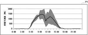
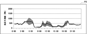
- the display control unit 644 generates screen data to be provided to the terminal device 70. Specifically, the display control unit 644 generates screen data constituting a power generation amount prediction screen P1 as shown in FIG. 3A and a power consumption amount prediction screen P2 as shown in FIG. 3B.
- the power generation amount prediction screen P1 in FIG. 3A shows a transition of the predicted power generation prediction value in a graph.
- the accuracy of the predicted value is represented by the degree of variation.
- a time zone with little variation indicates that the accuracy of the prediction value is high, that is, the reliability of the prediction value is high, while a time zone with a large variation has a low accuracy of the prediction value, that is, This indicates that the reliability of the predicted value is low.
- the display control unit 644 generates such a power generation amount prediction screen P1 based on the predicted value and accuracy information for each unit time for the power generation amount obtained by the prediction calculation unit 643 described above.
- the power consumption prediction screen P2 in FIG. 3B represents the transition of the predicted load predicted value (power consumption) in a graph. Also in this graph, the accuracy of the predicted value is represented by the degree of variation.
- the display control unit 644 generates such a power consumption amount prediction screen P2 based on the predicted value and accuracy information for each unit time for the power consumption amount obtained by the prediction calculation unit 643 described above.
- the power generation amount prediction screen P1 and the power consumption amount prediction screen P2 are examples, and other screens may be used.
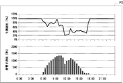
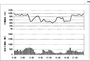
- the display control unit 644 may generate a power generation amount prediction screen P3 as shown in FIG. 4A and a power consumption amount prediction screen P4 as shown in FIG. 4B.
- the power generation prediction value and the prediction accuracy are represented by separate graphs. That is, the predicted power generation prediction value is represented by a bar graph for each time zone, while the prediction accuracy is represented by a time-series graph.
- the load prediction value (power consumption amount) and the prediction accuracy are represented by separate graphs. That is, the predicted load prediction value is represented by a bar graph for each time zone, while the prediction accuracy is represented by a time-series graph.
- the operation planning unit 645 obtains the predicted value obtained by the prediction calculation unit 643, the user schedule included in the user setting information 631, and the electricity price table 81 and weather forecast information 82 acquired from the server 80. Use it to make an operation plan.
- the accuracy of the predicted value obtained by the prediction calculation unit 643 is lower than a predetermined reference value, for example, when the variance is large, the operation planning unit 645 does not use the predicted value, Create an operation plan with other information alone.
- the operation plan planning unit 645 may set the tolerance for the predicted value to be larger than when the accuracy of the predicted value is high, and plan the operation plan. Good.
- the operation plan drafting unit 645 stores the operation plan drafted in this way in the data storage unit 63.
- the device control unit 646 controls the power storage facility 10 and the device 50 according to the operation plan planned by the operation plan planning unit 645, that is, the operation plan 634 of the data storage unit 63. In addition, the device control unit 646 periodically acquires the state of the device 50 by automatic control other than the operation plan 634 and adds or overwrites the management information 632 to the management information 632 for storage.
- the terminal device 70 is a mobile terminal including, for example, a tablet terminal and a smartphone, and is used by the user. Based on the screen data sent from the power control device 60, the terminal device 70 displays, for example, the power generation amount prediction screen P1 and the power consumption amount prediction screen P2 described above. In addition, the terminal device 70 receives a manual operation from the user and transmits the operation content to the power control device 60.
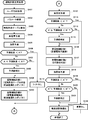
- FIG. 5 is a flowchart illustrating an example of an operation plan planning process executed by the control unit 64. This operation planning process is started, for example, periodically or in response to a request from a user who operates the terminal device 70.
- the control unit 64 acquires a user policy (step S101). That is, the information acquisition unit 641 acquires a user policy for expressing a policy for making an operation plan from the terminal device 70. Specifically, the information acquisition unit 641 acquires any user policy of economy, energy saving, and comfort. Note that the information acquisition unit 641 acquires the set user policy from the management information 632 if there is no new user request.
- the control unit 64 changes the parameter (step S102). For example, the control unit 64 changes parameters for optimizing the power supply selection in accordance with the acquired user policy.
- the control unit 64 acquires the electricity rate table 81 (step S103). That is, the information acquisition unit 641 controls the out-of-home communication unit 62 and acquires the electricity rate table 81 from the server 80 via the out-of-home network N2. Note that the information acquisition unit 641 accesses the server 80 to check whether or not the electricity rate table 81 has been updated. If the information has not been updated, the information acquisition unit 641 may acquire the acquired electricity rate table from the management information 632.
- the control unit 64 predicts the amount of power generation (step S104). That is, the prediction calculation unit 643 predicts the amount of power generated by the power generation facility 20. Specifically, the prediction calculation unit 643 obtains a prediction value every 30 minutes as an example, and gives accuracy information to the prediction value.
- the control unit 64 predicts the load (step S105). That is, the prediction calculation unit 643 predicts the amount of power consumed by the device 50. Also in this case, the prediction calculation unit 643 obtains a prediction value every 30 minutes as an example, and gives accuracy information to the prediction value.
- the control unit 64 may generate screen data for the predicted values predicted in steps S104 and S105 and display the screen data on the terminal device 70. That is, the display control unit 644 causes the terminal device 70 to display the above-described power generation amount prediction screen P1 illustrated in FIG. 3A and the above-described power consumption amount prediction screen P2 illustrated in FIG. 3B.
- the accuracy of the predicted value is represented by the degree of variation. In other words, a time zone with a small variation indicates that the accuracy of the predicted value is high, while a time zone with a large variation indicates that the accuracy of the predicted value is low. Therefore, the user can easily grasp the reliability of the predicted value of the power generation amount and the predicted value of the power consumption amount.
- the control unit 64 determines whether or not the prediction accuracy is lower than the reference value A (step S106). As the reference value A, a minimum value for trusting the predicted value is determined in advance. That is, the control unit 64 determines whether or not the predicted value is below the minimum reliability from the accuracy information given to the predicted value.
- control unit 64 determines whether the prediction accuracy is lower than the reference value B (step S107). For this reference value B, a lower limit value for sufficiently trusting the predicted value is determined in advance. That is, the control unit 64 determines whether or not the predicted value is below a sufficiently reliable lower limit.
- control unit 64 determines that the prediction accuracy is greater than or equal to the reference value B (step S107; No)
- the control unit 64 advances the process to step S109 described later.
- step S107 when it is determined that the prediction accuracy is lower than the reference value B (step S107; Yes), the control unit 64 corrects the prediction value (step S108). That is, since the accuracy of the predicted value does not exceed a sufficiently reliable standard, the control unit 64 takes into account the loss of prediction when the prediction is lost, for example, purchase of power for an insufficient amount of power. The predicted value is corrected to a low value so that it can be reduced.
- the control unit 64 drafts the heat storage control plan 1 (step S109). That is, the operation plan drafting unit 645 drafts an operation plan for the hot water heater included in the device 50, that is, the heat storage device, using the electricity rate table 81 acquired from the server 80. For example, the operation plan drafting unit 645 drafts an operation plan that shifts boiling of the water heater into a daytime time zone. The water heater is usually operated at midnight, but if there is a time zone where the electricity bill is low even in the daytime, the electricity bill table 81 is shifted to that time zone. At that time, for example, the operation planning unit 645 shifts boiling of the water heater on the condition that the power consumption in the shifted time zone does not exceed the peak cut level.
- the control unit 64 drafts the heat storage control plan 2 (step S110).
- the operation plan drafting unit 645 drafts an operation plan for the heat storage device using the generated power that is expected to be surplus in response to the power generation amount suppression. For example, when there is a time zone in which the surplus power generated during the daytime is larger than the power consumption of the water heater, the operation planning unit 645 shifts the boiling of the water heater during that time zone. That is, the operation planning unit 645 shifts the heating of the water heater on the condition that the power consumption amount in the shifted time zone does not exceed the predicted power generation amount.
- step S106 If it is determined in step S106 described above that the prediction accuracy is lower than the reference value A (step S106; Yes), the control unit 64 does not shift the boiling of the water heater (step S111).
- the control unit 64 re-predicts the load (step S112). That is, the prediction calculation unit 643 predicts the amount of power consumed by the device 50 based on the heat storage control plans 1 and 2 planned in steps S109 and S110 described above. Also in this case, the prediction calculation unit 643 obtains a prediction value every 30 minutes as an example, and gives accuracy information to the prediction value. At this time, the control unit 64 may generate screen data for the re-predicted predicted value and display the screen data on the terminal device 70.
- the control unit 64 determines whether or not the prediction accuracy is lower than the reference value A ′ (step S113).
- the reference value A ′ is a minimum value for trusting the predicted value. For example, a value that is more relaxed than the reference value A described above is determined in advance.
- the reference value A may be used instead of the reference value A ′.
- the control unit 64 determines whether the prediction accuracy is lower than the reference value B ′ (step S114).
- the reference value B ′ is a lower limit value for sufficiently trusting the predicted value. For example, a value that is more relaxed than the reference value B described above is determined in advance.
- the reference value B may be used instead of the reference value B ′.
- step S114 determines that the prediction accuracy is greater than or equal to the reference value B ′ (step S114; No).
- the control unit 64 proceeds to step S116 described later.
- step S114; Yes when it is determined that the prediction accuracy is lower than the reference value B ′ (step S114; Yes), the control unit 64 corrects the prediction value (step S115).
- the control unit 64 drafts a power saving control plan 1 (step S116).
- the operation plan drafting unit 645 drafts a power saving operation plan for each time zone for the device 50 capable of power saving control so as to be within the target electricity bill.
- the control unit 64 makes a power saving control plan 2 (step S117).
- the operation plan drafting unit 645 drafts a power saving operation plan for each time zone for the device 50 capable of power saving control in response to a demand response, that is, a DR command.
- the control unit 64 re-predicts the load (step S118). That is, the prediction calculation unit 643 predicts the amount of power consumed by the device 50 based on the power saving control plans 1 and 2 planned in steps S116 and S117 described above. Also in this case, the prediction calculation unit 643 obtains a prediction value every 30 minutes as an example, and gives accuracy information to the prediction value. At this time, the control unit 64 may generate screen data for the re-predicted predicted value and display the screen data on the terminal device 70.
- the control unit 64 determines whether or not the prediction accuracy is lower than the reference value A ′′ (step S119).
- This reference value A ′′ is a minimum value for trusting the predicted value, for example, A value that is more relaxed than the reference value A described above is determined in advance. In place of the reference value A ′′, the reference value A may be used.
- control unit 64 determines whether the prediction accuracy is lower than the reference value B ′′ (step S120).
- the reference value B ′′ is a lower limit value for sufficiently trusting the predicted value, and for example, a value that is more relaxed than the above-described reference value B is determined in advance. Instead of, reference value B may be used.
- step S120 determines that the prediction accuracy is greater than or equal to the reference value B ′′ (step S120; No).
- the control unit 64 proceeds to step S122 described later.
- the control unit 64 determines that the prediction accuracy is lower than the reference value B ′′. Then (step S120; Yes), the control unit 64 corrects the predicted value (step S121).
- the control unit 64 optimizes power supply selection (step S122). For example, the control unit 64 causes the power storage facility 10 to optimize charge / discharge control.
- step S119 If it is determined in step S119 described above that the prediction accuracy is lower than the reference value A ′′ (step S119; Yes), the control unit 64 notifies the power storage facility 10 that there is no change in charge / discharge control ( Step S123).
- Such an operation plan making process makes it possible to make an appropriate operation plan using the accuracy of the predicted value.
- the surplus power of the generated power is used to store or store heat, that is, in the case where the charging control of the storage facility 10 or the water heater included in the device 50 is operated, depending on the weather
- the fluctuation in the amount of power generated by the power generation facility 20 becomes large, and the actual value deviates significantly from the predicted value.
- a device 50 whose capacity cannot be easily changed such as a heat pump type hot water heater
- the power consumption exceeds the surplus power and power purchase occurs.
- an operation plan is created without using a predicted value with low accuracy or using a predicted value corrected according to accuracy. This can be avoided in advance.
- the operation calculation unit 643 can grasp the reliability of the predicted value in the operation planning unit 645 by statistically processing the relationship between the predicted value and the actual value and providing it as accuracy information of the predicted value.
- an operation plan utilizing the reliability of the predicted value can be made. For this reason, even if a prediction failure occurs, it is possible to suppress adverse effects that may occur while maintaining the operation of the device 50 in accordance with the user policy.
- the power control device 60 can change the handling of the predicted value according to the accuracy, and the processing load And no increase in memory requirements. Therefore, even if the power control device 60 is relatively low cost, the function can be realized.
- the display control unit 644 may generate an operation plan selection screen P5 as shown in FIG. 6A or an operation plan selection screen P6 as shown in FIG. 6B and display it on the terminal device 70. .
- These operation plan selection screens P5 and P6 allow the user to grasp the reliability of the prediction, thereby making it easier to select the operation plan.
- a display unit may be provided in the power control device 60 and various screens may be displayed on the display unit.
- the home system 1 has been described as an example, but the present invention can be similarly applied to, for example, a building system arranged in a building.
- the power control device 60 is disposed in the house H.
- the power control device 60 may be disposed outside the house H.
- the server 80 illustrated in FIG. 1 may function as the power control device 60.
- the cost of consumed power can be appropriately visualized and displayed.
- a program distribution method is arbitrary.
- a computer-readable medium including a CD-ROM (Compact Disc Read-Only Memory), a DVD (Digital Versatile Disc), an MO (Magneto Optical Disc), and a memory card can be read. It may be distributed by being stored in a recording medium, or distributed via a communication network including the Internet.
- the present invention can be employed in a power control apparatus, an operation plan planning method, and a program that can appropriately use a predicted value for power.
- 1 home system 10 power storage facility, 20 power generation facility, 30 breaker, 40 power measuring device, 50 device, 60 power control device, 61 in-home communication unit, 62 out-of-home communication unit, 63 data storage unit, 631 user setting information, 632 Management information, 633 prediction model, 634 operation plan, 64 control unit, 641 information acquisition unit, 642 prediction model update unit, 643 prediction calculation unit, 644 display control unit, 645 operation plan planning unit, 646 device control unit, 70 terminal device , 80 server, 81 electricity price table, 82 weather forecast information
Landscapes
- Engineering & Computer Science (AREA)
- Power Engineering (AREA)
- Environmental & Geological Engineering (AREA)
- Life Sciences & Earth Sciences (AREA)
- Atmospheric Sciences (AREA)
- Biodiversity & Conservation Biology (AREA)
- Ecology (AREA)
- Environmental Sciences (AREA)
- Supply And Distribution Of Alternating Current (AREA)
- Management, Administration, Business Operations System, And Electronic Commerce (AREA)
- Remote Monitoring And Control Of Power-Distribution Networks (AREA)
Abstract
Description
家庭内で消費又は発電される電力を制御する電力制御装置であり、前記電力についての予測値を表示装置に表示させる電力制御装置であって、
前記予測値の時間推移を表すグラフであり、前記予測値のばらつきを示したグラフを、前記表示装置に表示させる表示制御手段、
を備える。
図1は、本発明の実施形態に係るホームシステム1の全体構成の一例を示す模式図である。図示するように、ホームシステム1は、電力を蓄える蓄電設備10と、発電する発電設備20と、住居H内に供給される電力を遮断するブレーカ30と、住居H内で消費や発電される電力を計測する電力計測装置40と、住居H内で電力を消費する機器50と、ホームシステム1全体を制御する電力制御装置60と、ユーザに使用される端末装置70とを備えている。
上記の実施形態では、電力制御装置60が運転計画を立案し、そのまま使用する場合について説明したが、複数の運転計画をユーザに提示し、ユーザが何れかの運転計画を選択できるようにしてもよい。その際、上述した図3Aの発電量予測画面P1や図3Bの消費電力量予測画面P2を含めて提示することで、予測の信頼性を把握したユーザが、何れかの運転計画を選択し易くしてもよい。
Claims (6)
- 家庭内で消費又は発電される電力を制御する電力制御装置であり、前記電力についての予測値を表示装置に表示させる電力制御装置であって、
前記予測値の時間推移を表すグラフであり、前記予測値のばらつきを示したグラフを、前記表示装置に表示させる表示制御手段、
を備える電力制御装置。 - 家庭内で消費又は発電される電力を制御する電力制御装置であり、前記電力についての予測値を用いる電力制御装置であって、
前記予測値に付与された確度情報に応じて、前記予測値を用いて、若しくは、前記予測値を用いずに運転計画を立案する計画立案手段、
を備える電力制御装置。 - 前記計画立案手段は、前記確度情報に応じて、前記予測値を補正した後に、前記運転計画を立案する、
請求項2に記載の電力制御装置。 - 前記予測値及び前記確度情報を演算する予測演算手段を更に備える、
請求項2に記載の電力制御装置。 - 家庭内で消費又は発電される電力を制御する電力制御装置における運転計画立案方法であって、
前記電力についての予測値に付与された確度情報に応じて、前記予測値を用いて、若しくは、前記予測値を用いずに運転計画を立案する計画立案ステップ、
を備える運転計画立案方法。 - 家庭内で消費又は発電される電力を制御するコンピュータを、
前記電力についての予測値に付与された確度情報に応じて、前記予測値を用いて、若しくは、前記予測値を用いずに運転計画を立案する計画立案部、
として機能させるプログラム。
Priority Applications (6)
| Application Number | Priority Date | Filing Date | Title |
|---|---|---|---|
| CN201580084842.2A CN108292860B (zh) | 2015-12-10 | 2015-12-10 | 电力控制装置、运转计划制定方法以及记录介质 |
| BR112018008377-1A BR112018008377A2 (ja) | 2015-12-10 | 2015-12-10 | A power control unit, an operation planning method, and a program |
| US15/759,245 US11271400B2 (en) | 2015-12-10 | 2015-12-10 | Power control device, operation plan planning method, and recording medium |
| JP2017554736A JP6598876B2 (ja) | 2015-12-10 | 2015-12-10 | 電力制御装置、運転計画立案方法、及び、プログラム |
| EP15910247.4A EP3389162A4 (en) | 2015-12-10 | 2015-12-10 | Power control device, operation plan planning method, and program |
| PCT/JP2015/084661 WO2017098631A1 (ja) | 2015-12-10 | 2015-12-10 | 電力制御装置、運転計画立案方法、及び、プログラム |
Applications Claiming Priority (1)
| Application Number | Priority Date | Filing Date | Title |
|---|---|---|---|
| PCT/JP2015/084661 WO2017098631A1 (ja) | 2015-12-10 | 2015-12-10 | 電力制御装置、運転計画立案方法、及び、プログラム |
Publications (1)
| Publication Number | Publication Date |
|---|---|
| WO2017098631A1 true WO2017098631A1 (ja) | 2017-06-15 |
Family
ID=59013996
Family Applications (1)
| Application Number | Title | Priority Date | Filing Date |
|---|---|---|---|
| PCT/JP2015/084661 Ceased WO2017098631A1 (ja) | 2015-12-10 | 2015-12-10 | 電力制御装置、運転計画立案方法、及び、プログラム |
Country Status (6)
| Country | Link |
|---|---|
| US (1) | US11271400B2 (ja) |
| EP (1) | EP3389162A4 (ja) |
| JP (1) | JP6598876B2 (ja) |
| CN (1) | CN108292860B (ja) |
| BR (1) | BR112018008377A2 (ja) |
| WO (1) | WO2017098631A1 (ja) |
Cited By (14)
| Publication number | Priority date | Publication date | Assignee | Title |
|---|---|---|---|---|
| JP2019009868A (ja) * | 2017-06-22 | 2019-01-17 | 住友電気工業株式会社 | 制御計画作成装置、制御計画作成方法およびコンピュータプログラム |
| JP2019160291A (ja) * | 2018-03-12 | 2019-09-19 | 株式会社E.I.エンジニアリング | 運転支援システム、運転支援方法、これを実行させるためのコンピュータプログラム及びこのプログラムを記録した記録媒体 |
| WO2019187372A1 (ja) * | 2018-03-30 | 2019-10-03 | Necソリューションイノベータ株式会社 | 予測システム、モデル生成システム、方法およびプログラム |
| WO2020009649A1 (en) * | 2018-07-04 | 2020-01-09 | Epiroc Rock Drills Aktiebolag | Method and arrangement for managing power consumption in a mine |
| JP2020058101A (ja) * | 2018-09-28 | 2020-04-09 | 大和ハウス工業株式会社 | 電力供給システム |
| KR20200100626A (ko) * | 2017-11-27 | 2020-08-26 | 아이에이치아이 인코포레이티드 | 에너지 저장 시스템의 최적의 제어를 위한 시스템 및 방법 |
| JP2021032486A (ja) * | 2019-08-26 | 2021-03-01 | 三菱電機株式会社 | 制御装置、給湯システム、給湯機制御方法およびプログラム |
| JP2021100326A (ja) * | 2019-12-20 | 2021-07-01 | パナソニックIpマネジメント株式会社 | 電力制御ユニット、及び分電盤システム |
| JP2022103551A (ja) * | 2020-12-28 | 2022-07-08 | 国立大学法人東京工業大学 | 系統協調/分散型エネルギーシステムおよび情報プラットフォーム |
| JP2022550507A (ja) * | 2019-08-26 | 2022-12-02 | ヨアヒム・シュターツ | 電気エネルギー供給網の安定化のための方法 |
| JP2023008053A (ja) * | 2021-07-05 | 2023-01-19 | 三菱電機株式会社 | エネルギーマネジメントシステム、機器制御サーバ、エネルギーマネジメント方法、及び、プログラム |
| JP2023107061A (ja) * | 2022-01-21 | 2023-08-02 | 株式会社エナリス | 電力協調制御システム、電力協調制御方法及び電力協調制御プログラム |
| WO2024262093A1 (ja) * | 2023-06-23 | 2024-12-26 | 株式会社日立製作所 | 電力需給管理装置および電力需給管理方法 |
| CN120728626A (zh) * | 2025-05-16 | 2025-09-30 | 中国大唐集团科技创新有限公司 | 一种基于秒级风光功率预测的风光氢储系统中制氢功率前馈补偿方法 |
Families Citing this family (13)
| Publication number | Priority date | Publication date | Assignee | Title |
|---|---|---|---|---|
| US10444719B2 (en) * | 2016-07-29 | 2019-10-15 | Panasonic Intellectual Property Management Co., Ltd. | Energy management device and energy management method |
| EP3703221A4 (en) * | 2017-10-23 | 2021-06-16 | Sumitomo Electric Industries, Ltd. | ENERGY MANAGEMENT DEVICE, ENERGY MANAGEMENT SYSTEM AND ENERGY MANAGEMENT PROCEDURE |
| JP7143148B2 (ja) * | 2018-08-23 | 2022-09-28 | 三菱重工業株式会社 | 予測装置、予測方法、及びプログラム |
| JP7216566B2 (ja) * | 2019-02-19 | 2023-02-01 | 日立造船株式会社 | 情報処理装置、情報処理方法、および情報処理プログラム |
| EP3937346A4 (en) * | 2019-03-04 | 2022-05-04 | Asahi Kasei Kabushiki Kaisha | PLANNING DEVICE, CONTROL DEVICE, METHOD AND PROGRAM |
| WO2020195525A1 (ja) * | 2019-03-22 | 2020-10-01 | 株式会社カネカ | 電力制御システムおよび電力制御方法 |
| EP3739710B1 (en) * | 2019-05-13 | 2022-06-29 | Siemens Schweiz AG | Control of photovoltaic systems |
| FR3105516B1 (fr) * | 2019-12-20 | 2021-12-17 | Sagemcom Energy & Telecom Sas | Procédé de délestage de sorties d’une installation de production d’énergie électrique |
| KR102384980B1 (ko) * | 2020-05-15 | 2022-04-08 | 한국지역난방공사 | 신재생 열병합발전소를 활용한 가상발전소 시스템 및 이를 이용한 가상발전소 운영 방법 |
| US12047029B2 (en) * | 2020-09-10 | 2024-07-23 | Eric Robert ANDERSON | Electricity generation system and method |
| JP7824837B2 (ja) * | 2022-07-01 | 2026-03-05 | 株式会社東芝 | 情報処理装置、情報処理方法、コンピュータプログラム及び情報処理システム |
| US12626195B2 (en) * | 2022-11-29 | 2026-05-12 | Fmr Llc | Predicting user attributes using uncertainty estimate modeling |
| FR3142446A1 (fr) * | 2022-11-30 | 2024-05-31 | Psa Automobiles Sa | Procede de reutilisation de composants d’un systeme de chaine de traction de vehicule electrique dans un systeme d’alimentation electrique autonome non automobile |
Citations (3)
| Publication number | Priority date | Publication date | Assignee | Title |
|---|---|---|---|---|
| JP2004336890A (ja) * | 2003-05-08 | 2004-11-25 | Hitachi Ltd | 電力売買支援システム |
| JP2011259656A (ja) * | 2010-06-11 | 2011-12-22 | Mitsubishi Heavy Industries Mechatronics Systems Ltd | エネルギー管理装置、エネルギー管理方法、及びエネルギー管理プログラム |
| JP2014098601A (ja) | 2012-11-14 | 2014-05-29 | Hitachi Ltd | 日射量計算方法及び供給電力決定方法 |
Family Cites Families (22)
| Publication number | Priority date | Publication date | Assignee | Title |
|---|---|---|---|---|
| JP3966236B2 (ja) | 2003-06-19 | 2007-08-29 | 株式会社日立製作所 | 発電設備の運転計画方法及び発電設備の運転計画システム |
| US7860555B2 (en) * | 2005-02-02 | 2010-12-28 | Voyage Medical, Inc. | Tissue visualization and manipulation system |
| JP4245583B2 (ja) | 2005-04-15 | 2009-03-25 | 日本電信電話株式会社 | 分散型エネルギーシステムの制御装置、制御方法、プログラム、および記録媒体 |
| JP4808754B2 (ja) | 2008-08-28 | 2011-11-02 | 三菱電機株式会社 | 自然エネルギー発電制御システム |
| JP5294980B2 (ja) * | 2009-05-20 | 2013-09-18 | 株式会社日立製作所 | プラント運転データ予測システム及び方法 |
| JP5659486B2 (ja) * | 2009-12-17 | 2015-01-28 | 富士電機株式会社 | 発電計画作成方法および発電計画作成システム |
| US8392031B2 (en) * | 2011-02-28 | 2013-03-05 | General Electric Company | System and method for load forecasting |
| US9081374B2 (en) * | 2011-03-10 | 2015-07-14 | Deteotent Inc. | Calibrating algorithms for determining electrical load and lifestyle characteristics |
| JP5740215B2 (ja) * | 2011-06-10 | 2015-06-24 | クラリオン株式会社 | エネルギー消費量計算装置とそのエネルギー消費量計算方法 |
| JP2013012080A (ja) | 2011-06-29 | 2013-01-17 | Sharp Corp | 予測方法及び予測システム |
| JP5743881B2 (ja) * | 2011-12-28 | 2015-07-01 | 株式会社東芝 | 電力管理システム、電力管理方法、需要家端末及び電力管理装置 |
| JP5842654B2 (ja) * | 2012-02-14 | 2016-01-13 | オムロン株式会社 | システム制御装置およびシステム制御方法 |
| DE112012006017T5 (de) | 2012-03-12 | 2014-12-18 | Fujitsu Limited | Betriebsplan-Erschaffungssverfahren, Betriebsplan-Erschaffungsprogramm und Betriebsplan-Erschaffungsvorrichtung |
| JP6216377B2 (ja) * | 2013-06-27 | 2017-10-18 | パナソニック株式会社 | 電力調整装置、電力調整方法、電力調整システム、蓄電装置、サーバ、プログラム |
| JP6180826B2 (ja) * | 2013-07-02 | 2017-08-16 | 株式会社東芝 | エネルギー管理サーバ、エネルギー管理方法およびプログラム |
| JP6179237B2 (ja) | 2013-07-22 | 2017-08-16 | 富士通株式会社 | 電力消費量予測システム、方法、及びプログラム |
| US9846886B2 (en) * | 2013-11-07 | 2017-12-19 | Palo Alto Research Center Incorporated | Strategic modeling for economic optimization of grid-tied energy assets |
| JP2015162925A (ja) | 2014-02-26 | 2015-09-07 | 株式会社Nttファシリティーズ | 電力管理システム |
| CN103778486A (zh) * | 2014-02-28 | 2014-05-07 | 国家电网公司 | 一种配电网负荷预测方法 |
| JP6404650B2 (ja) * | 2014-09-11 | 2018-10-10 | 株式会社東芝 | 機器運転設定値決定装置、機器運転設定値決定方法、及び、機器運転設定値決定プログラム |
| JP6414743B2 (ja) * | 2014-11-28 | 2018-10-31 | 富士通株式会社 | 電源制御装置、電源制御プログラム、電源制御方法及び電源制御システム |
| KR101529678B1 (ko) * | 2014-12-31 | 2015-06-19 | 연세대학교 산학협력단 | 태양광 발전량을 극대화할 수 있는 복합식 태양광 추미 방법, 이를 이용한 태양광 추미 장치 및 태양광 발전 블라인드 시스템 |
-
2015
- 2015-12-10 BR BR112018008377-1A patent/BR112018008377A2/ja not_active Application Discontinuation
- 2015-12-10 EP EP15910247.4A patent/EP3389162A4/en not_active Withdrawn
- 2015-12-10 JP JP2017554736A patent/JP6598876B2/ja active Active
- 2015-12-10 CN CN201580084842.2A patent/CN108292860B/zh not_active Expired - Fee Related
- 2015-12-10 WO PCT/JP2015/084661 patent/WO2017098631A1/ja not_active Ceased
- 2015-12-10 US US15/759,245 patent/US11271400B2/en not_active Expired - Fee Related
Patent Citations (3)
| Publication number | Priority date | Publication date | Assignee | Title |
|---|---|---|---|---|
| JP2004336890A (ja) * | 2003-05-08 | 2004-11-25 | Hitachi Ltd | 電力売買支援システム |
| JP2011259656A (ja) * | 2010-06-11 | 2011-12-22 | Mitsubishi Heavy Industries Mechatronics Systems Ltd | エネルギー管理装置、エネルギー管理方法、及びエネルギー管理プログラム |
| JP2014098601A (ja) | 2012-11-14 | 2014-05-29 | Hitachi Ltd | 日射量計算方法及び供給電力決定方法 |
Non-Patent Citations (1)
| Title |
|---|
| See also references of EP3389162A4 |
Cited By (28)
| Publication number | Priority date | Publication date | Assignee | Title |
|---|---|---|---|---|
| JP2021192586A (ja) * | 2017-06-22 | 2021-12-16 | 住友電気工業株式会社 | 制御計画作成装置、制御計画作成方法およびコンピュータプログラム |
| JP2019009868A (ja) * | 2017-06-22 | 2019-01-17 | 住友電気工業株式会社 | 制御計画作成装置、制御計画作成方法およびコンピュータプログラム |
| KR102749895B1 (ko) * | 2017-11-27 | 2025-01-07 | 아이에이치아이 인코포레이티드 | 에너지 저장 시스템의 최적의 제어를 위한 시스템 및 방법 |
| US11876374B2 (en) | 2017-11-27 | 2024-01-16 | Ihi Terrasun Solutions Inc. | System and method for optimal control of energy storage system |
| JP2023129546A (ja) * | 2017-11-27 | 2023-09-14 | アイエイチアイ テラサン ソリューションズ インコーポレイテッド | エネルギ貯蔵システムを最適に制御するためのシステム及び方法 |
| KR20200100626A (ko) * | 2017-11-27 | 2020-08-26 | 아이에이치아이 인코포레이티드 | 에너지 저장 시스템의 최적의 제어를 위한 시스템 및 방법 |
| JP7320503B2 (ja) | 2017-11-27 | 2023-08-03 | アイエイチアイ テラサン ソリューションズ インコーポレイテッド | エネルギ貯蔵システムを最適に制御するためのシステム及び方法 |
| JP2021505103A (ja) * | 2017-11-27 | 2021-02-15 | アイエイチアイ インコーポレイテッド | エネルギ貯蔵システムを最適に制御するためのシステム及び方法 |
| JP2019160291A (ja) * | 2018-03-12 | 2019-09-19 | 株式会社E.I.エンジニアリング | 運転支援システム、運転支援方法、これを実行させるためのコンピュータプログラム及びこのプログラムを記録した記録媒体 |
| JPWO2019187372A1 (ja) * | 2018-03-30 | 2021-02-12 | Necソリューションイノベータ株式会社 | 予測システム、モデル生成システム、方法およびプログラム |
| CN111937084A (zh) * | 2018-03-30 | 2020-11-13 | 日本电气方案创新株式会社 | 预测系统、模型生成系统、方法和程序 |
| WO2019187372A1 (ja) * | 2018-03-30 | 2019-10-03 | Necソリューションイノベータ株式会社 | 予測システム、モデル生成システム、方法およびプログラム |
| JP7007027B2 (ja) | 2018-03-30 | 2022-01-24 | Necソリューションイノベータ株式会社 | 予測システム、モデル生成システム、方法およびプログラム |
| WO2020009649A1 (en) * | 2018-07-04 | 2020-01-09 | Epiroc Rock Drills Aktiebolag | Method and arrangement for managing power consumption in a mine |
| JP2020058101A (ja) * | 2018-09-28 | 2020-04-09 | 大和ハウス工業株式会社 | 電力供給システム |
| JP7203551B2 (ja) | 2018-09-28 | 2023-01-13 | 大和ハウス工業株式会社 | 電力供給システム |
| JP7601859B2 (ja) | 2019-08-26 | 2024-12-17 | ヨアヒム・シュターツ | 電気エネルギー供給網の安定化のための方法 |
| JP7267149B2 (ja) | 2019-08-26 | 2023-05-01 | 三菱電機株式会社 | 制御装置、給湯システム、給湯機制御方法およびプログラム |
| JP2022550507A (ja) * | 2019-08-26 | 2022-12-02 | ヨアヒム・シュターツ | 電気エネルギー供給網の安定化のための方法 |
| JP2021032486A (ja) * | 2019-08-26 | 2021-03-01 | 三菱電機株式会社 | 制御装置、給湯システム、給湯機制御方法およびプログラム |
| JP2021100326A (ja) * | 2019-12-20 | 2021-07-01 | パナソニックIpマネジメント株式会社 | 電力制御ユニット、及び分電盤システム |
| JP2022103551A (ja) * | 2020-12-28 | 2022-07-08 | 国立大学法人東京工業大学 | 系統協調/分散型エネルギーシステムおよび情報プラットフォーム |
| JP7671486B2 (ja) | 2020-12-28 | 2025-05-02 | 国立大学法人東京科学大学 | 系統協調/分散型エネルギーシステム |
| JP2023008053A (ja) * | 2021-07-05 | 2023-01-19 | 三菱電機株式会社 | エネルギーマネジメントシステム、機器制御サーバ、エネルギーマネジメント方法、及び、プログラム |
| JP2023107061A (ja) * | 2022-01-21 | 2023-08-02 | 株式会社エナリス | 電力協調制御システム、電力協調制御方法及び電力協調制御プログラム |
| WO2024262093A1 (ja) * | 2023-06-23 | 2024-12-26 | 株式会社日立製作所 | 電力需給管理装置および電力需給管理方法 |
| CN120728626A (zh) * | 2025-05-16 | 2025-09-30 | 中国大唐集团科技创新有限公司 | 一种基于秒级风光功率预测的风光氢储系统中制氢功率前馈补偿方法 |
| CN120728626B (zh) * | 2025-05-16 | 2026-04-03 | 中国大唐集团科技创新有限公司 | 一种基于秒级风光功率预测的风光氢储系统中制氢功率前馈补偿方法 |
Also Published As
| Publication number | Publication date |
|---|---|
| EP3389162A4 (en) | 2018-12-05 |
| EP3389162A1 (en) | 2018-10-17 |
| US11271400B2 (en) | 2022-03-08 |
| JPWO2017098631A1 (ja) | 2018-03-22 |
| JP6598876B2 (ja) | 2019-10-30 |
| CN108292860A (zh) | 2018-07-17 |
| BR112018008377A2 (ja) | 2018-10-23 |
| CN108292860B (zh) | 2022-04-08 |
| US20180262003A1 (en) | 2018-09-13 |
Similar Documents
| Publication | Publication Date | Title |
|---|---|---|
| JP6598876B2 (ja) | 電力制御装置、運転計画立案方法、及び、プログラム | |
| US11502534B2 (en) | Electrical energy storage system with battery state-of-charge estimation | |
| JP5959783B1 (ja) | 電力管理装置 | |
| JP5095495B2 (ja) | 電力システムおよびその制御方法 | |
| US10298056B2 (en) | Power control system, power control method, and recording medium | |
| JP6249895B2 (ja) | 電力制御システム、方法及び電力制御装置 | |
| JP6069738B2 (ja) | 充放電制御システム、充放電制御方法、および充放電制御プログラム | |
| JP2020054214A (ja) | 蓄電池管理装置および蓄電池管理方法 | |
| US9651975B2 (en) | System, method and apparatus for power demand adjustment based on consumer annoyance | |
| JP6676477B2 (ja) | 建物の消費電力予測システム、蓄電装置の制御システム、及び蓄電装置の制御方法 | |
| JP6403875B2 (ja) | 機器管理装置、機器管理システム、機器管理方法及びプログラム | |
| US20180254636A1 (en) | Management device and control method | |
| CN104285353B (zh) | 能量管理设备、能量管理方法 | |
| JP6664479B2 (ja) | 制御装置、電力管理システム、充放電の制御方法及びプログラム | |
| JP2012092579A (ja) | 中水利用管理システム | |
| JP2020022339A (ja) | 電力管理システム、電力管理装置及びプログラム | |
| WO2016031065A1 (ja) | 消費電力推定装置、機器管理システム、消費電力推定方法及びプログラム | |
| EP4742479A1 (en) | Power operation system | |
| JP2022066217A (ja) | 給湯方法、及び、制御装置 | |
| JP2025035895A (ja) | 電源制御装置、電源制御方法、プログラム | |
| JP2013242165A (ja) | 表示装置及び表示方法 | |
| JP2019009868A (ja) | 制御計画作成装置、制御計画作成方法およびコンピュータプログラム |
Legal Events
| Date | Code | Title | Description |
|---|---|---|---|
| 121 | Ep: the epo has been informed by wipo that ep was designated in this application |
Ref document number: 15910247 Country of ref document: EP Kind code of ref document: A1 |
|
| ENP | Entry into the national phase |
Ref document number: 2017554736 Country of ref document: JP Kind code of ref document: A |
|
| WWE | Wipo information: entry into national phase |
Ref document number: 15759245 Country of ref document: US |
|
| REG | Reference to national code |
Ref country code: BR Ref legal event code: B01A Ref document number: 112018008377 Country of ref document: BR |
|
| NENP | Non-entry into the national phase |
Ref country code: DE |
|
| ENP | Entry into the national phase |
Ref document number: 112018008377 Country of ref document: BR Kind code of ref document: A2 Effective date: 20180425 |