WO2017098867A1 - 二重容器及びその製造方法 - Google Patents
二重容器及びその製造方法 Download PDFInfo
- Publication number
- WO2017098867A1 WO2017098867A1 PCT/JP2016/083824 JP2016083824W WO2017098867A1 WO 2017098867 A1 WO2017098867 A1 WO 2017098867A1 JP 2016083824 W JP2016083824 W JP 2016083824W WO 2017098867 A1 WO2017098867 A1 WO 2017098867A1
- Authority
- WO
- WIPO (PCT)
- Prior art keywords
- container
- flexible inner
- outer layer
- rigid outer
- inner layer
- Prior art date
- Legal status (The legal status is an assumption and is not a legal conclusion. Google has not performed a legal analysis and makes no representation as to the accuracy of the status listed.)
- Ceased
Links
Images


Classifications
-
- B—PERFORMING OPERATIONS; TRANSPORTING
- B65—CONVEYING; PACKING; STORING; HANDLING THIN OR FILAMENTARY MATERIAL
- B65D—CONTAINERS FOR STORAGE OR TRANSPORT OF ARTICLES OR MATERIALS, e.g. BAGS, BARRELS, BOTTLES, BOXES, CANS, CARTONS, CRATES, DRUMS, JARS, TANKS, HOPPERS, FORWARDING CONTAINERS; ACCESSORIES, CLOSURES, OR FITTINGS THEREFOR; PACKAGING ELEMENTS; PACKAGES
- B65D1/00—Rigid or semi-rigid containers having bodies formed in one piece, e.g. by casting metallic material, by moulding plastics, by blowing vitreous material, by throwing ceramic material, by moulding pulped fibrous material or by deep-drawing operations performed on sheet material
- B65D1/02—Bottles or similar containers with necks or like restricted apertures, designed for pouring contents
- B65D1/0207—Bottles or similar containers with necks or like restricted apertures, designed for pouring contents characterised by material, e.g. composition, physical features
- B65D1/0215—Bottles or similar containers with necks or like restricted apertures, designed for pouring contents characterised by material, e.g. composition, physical features multilayered
-
- B—PERFORMING OPERATIONS; TRANSPORTING
- B29—WORKING OF PLASTICS; WORKING OF SUBSTANCES IN A PLASTIC STATE IN GENERAL
- B29C—SHAPING OR JOINING OF PLASTICS; SHAPING OF MATERIAL IN A PLASTIC STATE, NOT OTHERWISE PROVIDED FOR; AFTER-TREATMENT OF THE SHAPED PRODUCTS, e.g. REPAIRING
- B29C49/00—Blow-moulding, i.e. blowing a preform or parison to a desired shape within a mould; Apparatus therefor
- B29C49/22—Blow-moulding, i.e. blowing a preform or parison to a desired shape within a mould; Apparatus therefor using multilayered preforms or parisons
-
- B—PERFORMING OPERATIONS; TRANSPORTING
- B29—WORKING OF PLASTICS; WORKING OF SUBSTANCES IN A PLASTIC STATE IN GENERAL
- B29C—SHAPING OR JOINING OF PLASTICS; SHAPING OF MATERIAL IN A PLASTIC STATE, NOT OTHERWISE PROVIDED FOR; AFTER-TREATMENT OF THE SHAPED PRODUCTS, e.g. REPAIRING
- B29C49/00—Blow-moulding, i.e. blowing a preform or parison to a desired shape within a mould; Apparatus therefor
- B29C49/42—Component parts, details or accessories; Auxiliary operations
- B29C49/4273—Auxiliary operations after the blow-moulding operation not otherwise provided for
-
- B—PERFORMING OPERATIONS; TRANSPORTING
- B29—WORKING OF PLASTICS; WORKING OF SUBSTANCES IN A PLASTIC STATE IN GENERAL
- B29C—SHAPING OR JOINING OF PLASTICS; SHAPING OF MATERIAL IN A PLASTIC STATE, NOT OTHERWISE PROVIDED FOR; AFTER-TREATMENT OF THE SHAPED PRODUCTS, e.g. REPAIRING
- B29C49/00—Blow-moulding, i.e. blowing a preform or parison to a desired shape within a mould; Apparatus therefor
- B29C49/42—Component parts, details or accessories; Auxiliary operations
- B29C49/48—Moulds
- B29C49/4802—Moulds with means for locally compressing part(s) of the parison in the main blowing cavity
-
- B—PERFORMING OPERATIONS; TRANSPORTING
- B32—LAYERED PRODUCTS
- B32B—LAYERED PRODUCTS, i.e. PRODUCTS BUILT-UP OF STRATA OF FLAT OR NON-FLAT, e.g. CELLULAR OR HONEYCOMB, FORM
- B32B27/00—Layered products comprising a layer of synthetic resin
- B32B27/06—Layered products comprising a layer of synthetic resin as the main or only constituent of a layer, which is next to another layer of the same or of a different material
- B32B27/08—Layered products comprising a layer of synthetic resin as the main or only constituent of a layer, which is next to another layer of the same or of a different material of synthetic resin
-
- B—PERFORMING OPERATIONS; TRANSPORTING
- B32—LAYERED PRODUCTS
- B32B—LAYERED PRODUCTS, i.e. PRODUCTS BUILT-UP OF STRATA OF FLAT OR NON-FLAT, e.g. CELLULAR OR HONEYCOMB, FORM
- B32B27/00—Layered products comprising a layer of synthetic resin
- B32B27/30—Layered products comprising a layer of synthetic resin comprising vinyl (co)polymers; comprising acrylic (co)polymers
- B32B27/306—Layered products comprising a layer of synthetic resin comprising vinyl (co)polymers; comprising acrylic (co)polymers comprising vinyl acetate or vinyl alcohol (co)polymers
-
- B—PERFORMING OPERATIONS; TRANSPORTING
- B32—LAYERED PRODUCTS
- B32B—LAYERED PRODUCTS, i.e. PRODUCTS BUILT-UP OF STRATA OF FLAT OR NON-FLAT, e.g. CELLULAR OR HONEYCOMB, FORM
- B32B27/00—Layered products comprising a layer of synthetic resin
- B32B27/32—Layered products comprising a layer of synthetic resin comprising polyolefins
-
- B—PERFORMING OPERATIONS; TRANSPORTING
- B65—CONVEYING; PACKING; STORING; HANDLING THIN OR FILAMENTARY MATERIAL
- B65D—CONTAINERS FOR STORAGE OR TRANSPORT OF ARTICLES OR MATERIALS, e.g. BAGS, BARRELS, BOTTLES, BOXES, CANS, CARTONS, CRATES, DRUMS, JARS, TANKS, HOPPERS, FORWARDING CONTAINERS; ACCESSORIES, CLOSURES, OR FITTINGS THEREFOR; PACKAGING ELEMENTS; PACKAGES
- B65D1/00—Rigid or semi-rigid containers having bodies formed in one piece, e.g. by casting metallic material, by moulding plastics, by blowing vitreous material, by throwing ceramic material, by moulding pulped fibrous material or by deep-drawing operations performed on sheet material
- B65D1/02—Bottles or similar containers with necks or like restricted apertures, designed for pouring contents
-
- B—PERFORMING OPERATIONS; TRANSPORTING
- B65—CONVEYING; PACKING; STORING; HANDLING THIN OR FILAMENTARY MATERIAL
- B65D—CONTAINERS FOR STORAGE OR TRANSPORT OF ARTICLES OR MATERIALS, e.g. BAGS, BARRELS, BOTTLES, BOXES, CANS, CARTONS, CRATES, DRUMS, JARS, TANKS, HOPPERS, FORWARDING CONTAINERS; ACCESSORIES, CLOSURES, OR FITTINGS THEREFOR; PACKAGING ELEMENTS; PACKAGES
- B65D1/00—Rigid or semi-rigid containers having bodies formed in one piece, e.g. by casting metallic material, by moulding plastics, by blowing vitreous material, by throwing ceramic material, by moulding pulped fibrous material or by deep-drawing operations performed on sheet material
- B65D1/02—Bottles or similar containers with necks or like restricted apertures, designed for pouring contents
- B65D1/0223—Bottles or similar containers with necks or like restricted apertures, designed for pouring contents characterised by shape
- B65D1/0261—Bottom construction
- B65D1/0276—Bottom construction having a continuous contact surface, e.g. Champagne-type bottom
-
- B—PERFORMING OPERATIONS; TRANSPORTING
- B65—CONVEYING; PACKING; STORING; HANDLING THIN OR FILAMENTARY MATERIAL
- B65D—CONTAINERS FOR STORAGE OR TRANSPORT OF ARTICLES OR MATERIALS, e.g. BAGS, BARRELS, BOTTLES, BOXES, CANS, CARTONS, CRATES, DRUMS, JARS, TANKS, HOPPERS, FORWARDING CONTAINERS; ACCESSORIES, CLOSURES, OR FITTINGS THEREFOR; PACKAGING ELEMENTS; PACKAGES
- B65D23/00—Details of bottles or jars not otherwise provided for
- B65D23/001—Supporting means fixed to the container
-
- B—PERFORMING OPERATIONS; TRANSPORTING
- B65—CONVEYING; PACKING; STORING; HANDLING THIN OR FILAMENTARY MATERIAL
- B65D—CONTAINERS FOR STORAGE OR TRANSPORT OF ARTICLES OR MATERIALS, e.g. BAGS, BARRELS, BOTTLES, BOXES, CANS, CARTONS, CRATES, DRUMS, JARS, TANKS, HOPPERS, FORWARDING CONTAINERS; ACCESSORIES, CLOSURES, OR FITTINGS THEREFOR; PACKAGING ELEMENTS; PACKAGES
- B65D77/00—Packages formed by enclosing articles or materials in preformed containers, e.g. boxes, cartons, sacks or bags
- B65D77/04—Articles or materials enclosed in two or more containers disposed one within another
- B65D77/06—Liquids or semi-liquids or other materials or articles enclosed in flexible containers disposed within rigid containers
-
- B—PERFORMING OPERATIONS; TRANSPORTING
- B65—CONVEYING; PACKING; STORING; HANDLING THIN OR FILAMENTARY MATERIAL
- B65D—CONTAINERS FOR STORAGE OR TRANSPORT OF ARTICLES OR MATERIALS, e.g. BAGS, BARRELS, BOTTLES, BOXES, CANS, CARTONS, CRATES, DRUMS, JARS, TANKS, HOPPERS, FORWARDING CONTAINERS; ACCESSORIES, CLOSURES, OR FITTINGS THEREFOR; PACKAGING ELEMENTS; PACKAGES
- B65D83/00—Containers or packages with special means for dispensing contents
- B65D83/771—Containers or packages with special means for dispensing contents for dispensing fluent contents by means of a flexible bag or a deformable membrane or diaphragm
- B65D83/7711—Containers or packages with special means for dispensing contents for dispensing fluent contents by means of a flexible bag or a deformable membrane or diaphragm the contents of a flexible bag being expelled by the contracting forces inherent in the bag or a sleeve fitting snugly around the bag
-
- B—PERFORMING OPERATIONS; TRANSPORTING
- B29—WORKING OF PLASTICS; WORKING OF SUBSTANCES IN A PLASTIC STATE IN GENERAL
- B29C—SHAPING OR JOINING OF PLASTICS; SHAPING OF MATERIAL IN A PLASTIC STATE, NOT OTHERWISE PROVIDED FOR; AFTER-TREATMENT OF THE SHAPED PRODUCTS, e.g. REPAIRING
- B29C49/00—Blow-moulding, i.e. blowing a preform or parison to a desired shape within a mould; Apparatus therefor
- B29C49/42—Component parts, details or accessories; Auxiliary operations
- B29C49/48—Moulds
- B29C49/4802—Moulds with means for locally compressing part(s) of the parison in the main blowing cavity
- B29C2049/4805—Moulds with means for locally compressing part(s) of the parison in the main blowing cavity by closing the mould halves
-
- B—PERFORMING OPERATIONS; TRANSPORTING
- B29—WORKING OF PLASTICS; WORKING OF SUBSTANCES IN A PLASTIC STATE IN GENERAL
- B29K—INDEXING SCHEME ASSOCIATED WITH SUBCLASSES B29B, B29C OR B29D, RELATING TO MOULDING MATERIALS OR TO MATERIALS FOR MOULDS, REINFORCEMENTS, FILLERS OR PREFORMED PARTS, e.g. INSERTS
- B29K2023/00—Use of polyalkenes or derivatives thereof as moulding material
- B29K2023/04—Polymers of ethylene
- B29K2023/06—PE, i.e. polyethylene
- B29K2023/0608—PE, i.e. polyethylene characterised by its density
- B29K2023/0633—LDPE, i.e. low density polyethylene
-
- B—PERFORMING OPERATIONS; TRANSPORTING
- B29—WORKING OF PLASTICS; WORKING OF SUBSTANCES IN A PLASTIC STATE IN GENERAL
- B29K—INDEXING SCHEME ASSOCIATED WITH SUBCLASSES B29B, B29C OR B29D, RELATING TO MOULDING MATERIALS OR TO MATERIALS FOR MOULDS, REINFORCEMENTS, FILLERS OR PREFORMED PARTS, e.g. INSERTS
- B29K2023/00—Use of polyalkenes or derivatives thereof as moulding material
- B29K2023/04—Polymers of ethylene
- B29K2023/08—Copolymers of ethylene
- B29K2023/086—EVOH, i.e. ethylene vinyl alcohol copolymer
-
- B—PERFORMING OPERATIONS; TRANSPORTING
- B29—WORKING OF PLASTICS; WORKING OF SUBSTANCES IN A PLASTIC STATE IN GENERAL
- B29K—INDEXING SCHEME ASSOCIATED WITH SUBCLASSES B29B, B29C OR B29D, RELATING TO MOULDING MATERIALS OR TO MATERIALS FOR MOULDS, REINFORCEMENTS, FILLERS OR PREFORMED PARTS, e.g. INSERTS
- B29K2023/00—Use of polyalkenes or derivatives thereof as moulding material
- B29K2023/10—Polymers of propylene
- B29K2023/12—PP, i.e. polypropylene
-
- B—PERFORMING OPERATIONS; TRANSPORTING
- B29—WORKING OF PLASTICS; WORKING OF SUBSTANCES IN A PLASTIC STATE IN GENERAL
- B29L—INDEXING SCHEME ASSOCIATED WITH SUBCLASS B29C, RELATING TO PARTICULAR ARTICLES
- B29L2031/00—Other particular articles
- B29L2031/712—Containers; Packaging elements or accessories, Packages
-
- B—PERFORMING OPERATIONS; TRANSPORTING
- B32—LAYERED PRODUCTS
- B32B—LAYERED PRODUCTS, i.e. PRODUCTS BUILT-UP OF STRATA OF FLAT OR NON-FLAT, e.g. CELLULAR OR HONEYCOMB, FORM
- B32B2439/00—Containers; Receptacles
Definitions
- the present invention relates to a double container and a manufacturing method thereof. More specifically, the present invention includes a relatively rigid outer container, sometimes referred to as a delamination bottle, a laminated container, and the like, and a flexible inner container in which the capacity can be changed in accordance with the filling amount of the contents in the outer container.
- the present invention relates to a double container and a method for manufacturing the same, and a double container that can be easily manufactured with a molding material and a molding apparatus that are not greatly different from conventional ones.
- the direction is shown with the double container standing vertically, the vertical direction, that is, the vertical direction is the direction of the center line when the double container is cylindrical, and the horizontal direction is the center of the double container. It is a direction orthogonal to the direction of the line.
- the split mold is typically a mold divided into two, but does not exclude molds divided into other numbers.
- the container can prevent oxidation of the contained material without touching the outside air even if the amount of the contained material is reduced by using a part of the contained material. That is, in a general container, after filling the contents, it is possible to prevent oxidation of the contents until the filling container is opened by evacuating the space in the container or filling with an inert gas such as nitrogen gas. Easy. However, in the case of a general rigid container, when the container is opened and a part of the stored item is consumed, and the remaining used item remains in the container, the volume corresponding to the consumed amount of the stored item in the container The outside air enters and the residual contents are oxidized. In order to prevent this oxidation, the contents may contain an antioxidant, but the inclusion of the antioxidant is not preferable from the viewpoint of health or the like.
- the container is composed of a rigid outer container (rigid outer layer container part) and a flexible inner container (flexible inner layer container part). Even if a part of the contents is consumed, the rigid outer container is not deformed, maintains its self-supporting property, and the volume of the flexible inner container is reduced by an amount corresponding to the consumption of the stored object, so that the outside air is discharged into the flexible inner container. Is manufactured and used as a seasoning container, cosmetic container, and the like.
- the liquid may also be stored in a deformable container.
- the container is deflated and deformed from the initial shape by the use of the contents.
- the container that has become distorted becomes ugly and has a problem that it is not preferable to place it on a restaurant table, for example.
- a cautionary note for food use, a shelf life, an allergy-related cautionary note, performance, and the like are described. There is a problem that these descriptions are difficult to read or cannot be read due to the wrinkle deformation of the container.
- the residual contents gather at the intermediate members and corners of the container, so that the container does not stand vertically on the plane or the residual contents are discharged from the container. There is a problem that it must be moved to the vicinity of the discharge port.
- the container is composed of a rigid outer container (rigid outer layer container part) and a flexible inner container (flexible inner layer container part).
- a configuration has been proposed in which the rigid outer container is not deformed, the volume of the flexible inner container is reduced by an amount corresponding to the consumption of the stored object, and the flexible inner container does not allow outside air to enter, It is used as a container for liquid seasonings such as soy sauce.
- a flexible inner container that accommodates the contents and deforms in accordance with a decrease in the contents, and the inner container is elastically deformed and sucks outside air between the inner container and the inner container A container body having an outer container formed with an air intake hole, a discharge port for discharging the contents is formed on the top surface part, a discharge cap attached to the mouth part of the container body, A discharge container comprising: an outside air introduction hole that communicates with the intake hole; and an air valve portion that switches between communication between the outside air introduction hole and the intake hole and blocking of the intake hole.
- the above-mentioned rigid outer container is not deformed, and the volume of the flexible inner container is reduced by an amount corresponding to the consumption of the stored items, and the solution is achieved in a double container having a flexible inner container that can be deformed without entering outside air.
- the problem that must be solved is that the flexible inner container is in contact with the inner surface of the outer container at the time of manufacture, and the flexible inner container is peeled off from the inner surface of the outer container in accordance with the consumption of the contents. During this period, outside air must be inhaled.
- the opening for inhaling the outside air is formed relatively easily, it comprises an outer layer that forms an outer shell, and an inner layer that is detachably laminated on the outer layer and forms an inner bag.
- a synthetic resin blow-molded container which is an outer layer portion laminated in the vicinity of the distal end portion of the bulging portion of the inner layer formed on the peripheral wall of the mouth tube portion, with the distal end peripheral edge as a proximal end portion,
- a flat knob is formed upright so that it can be shredded, and the base end has a notch shape, and the bulging portion of the inner layer bulges a part of the peripheral wall of the mouth tube portion together with the outer layer during blow molding of the container
- the knob is formed by pressing the outer layer portion laminated in the vicinity of the distal end portion of the inner layer into a pressing shape on the mating surface of the split mold used for blow molding,
- the notch shape is the shape of the mold cavity when the bulge is formed.
- the outer layer is peeled off from the vicinity of the tip of the inner layer with the knob, and an intake hole for introducing outside air is formed between the outer layer and the inner layer.
- a resin blow molded container has been proposed (see, for example, Patent Document 2).
- the bottom part of the double container is formed by sandwiching a parison made of a material for a rigid outer container and a material for a flexible inner container at the middle part in the vertical direction of the split mold and then blowing. Therefore, in the parting line at the bottom of the double container, the material for the rigid outer container and the material for the flexible inner container, which are mutually peelable, are integrated. Therefore, in the parting line at the bottom of the double container, the material for the focus rigid outer container and the material for the flexible inner container will eventually peel apart unless special measures are taken, and between the rigid outer container and the flexible inner container. There is a gap for outside air. As a result, when the contents of the double container decrease and the volume of the flexible inner container decreases, the bottom part of the flexible inner container fixed to the upper spout part lifts from the bottom part of the rigid outer container.
- the flexible inner container is wrinkled and deformed from the original substantially cylindrical shape or rectangular shape.
- the suction pipe of the pouring pump extends to the vicinity of the bottom, the contents remain.
- This residue of the contents is not only economically unfavorable, but also poor in appearance, and is not particularly preferable as a cosmetic container.
- the remaining amount is not constant because the deformation of the flexible inner container varies depending on the individual container. To accommodate a predetermined usable amount, an extra amount more than the predetermined amount is filled. There is a waste that must be kept.
- any of these conventional techniques form an opening or a gap for taking outside air between the flexible inner container and the rigid outer container separated from each other in the upper part of the double container.
- both are firmly fixed and integrated with a special configuration so as not to form an opening or gap for taking in the outside air at the bottom.
- Patent Document 1 When the discharge container proposed by Patent Document 1 is a so-called liquid seasoning such as soy sauce or vinegar whose contents are a viscous liquid resembling pure water having a low viscosity, a predetermined operation, that is, an outer container is used. Without deformation, the volume of the flexible inner container can be reduced by an amount corresponding to the consumption of the contents to prevent outside air from entering the flexible inner container, thereby preventing the contents from being oxidized. However, no measures are taken for the problem that the consumption of the contents progresses and the contents are reduced to leave the bottom.
- liquid seasoning such as soy sauce or vinegar whose contents are a viscous liquid resembling pure water having a low viscosity
- the delamination container disclosed in Citation 3 presses the pump dispenser against the bottom of the container, and it is an essential requirement that the delamination container has a pump dispenser. Therefore, the feasible range of the invention disclosed in the cited document 3 is narrow.
- the blow-molded container disclosed in the cited document 4 has a biting portion in which a molding die for molding projects from the abutting surface. If there is a bite that protrudes from the abutment surface, the mold bit will increase the manufacturing cost of the mold, and the protruding bit makes it difficult to manage and maintain the mold. Prevent efficient repairs.
- the adhesive layer of the blow-molded container disclosed in the cited document 5 uses a multi-layer extrusion die having a complicated configuration having an adhesive flow path, and a complicated operation control circuit for that purpose. Therefore, it is inevitable that the manufacturing cost becomes very high as compared with the case having no adhesive layer.
- the present invention has been made in view of the above-described problems of a double container comprising a relatively rigid outer container and a flexible inner container whose capacity can be changed in accordance with the amount of the contents contained in the outer container. It is.
- the present invention can be easily manufactured by a molding material / molding apparatus that is not greatly different from the conventional one, and even if the contents are consumed and the contents are reduced and the inner volume of the flexible inner container is reduced, the bottom of the inner container is reduced. It is an object of the present invention to provide a double container and a method for manufacturing the same that does not rise away from the bottom of the outer container.
- the first invention is a double container formed by blow molding a parison having an outer layer for a rigid outer layer container part and an inner layer for a flexible inner layer container part, It has a container bottom that is blow-molded after sandwiching the vertical middle part of the parison from the horizontal direction by a split mold, and at least a part of the container bottom is a part sandwiched by the split mold,
- the container bottom portion has a bottom protrusion formed of an outer layer of the rigid outer layer container portion and an outer layer of the flexible inner layer container portion on the lower side of the container bottom portion, and the rigid outer layer container portion is extended at the bottom protrusion portion.
- extension part of the flexible inner layer container part have irregularities with different heights in the horizontal direction, and the irregularity does not cause the extension part of the rigid outer layer container part and the extension part of the flexible inner layer container part to be displaced from each other in the vertical direction. It is a double container characterized by being assembled together.
- the standing double container in which a gutter member is attached around the bottom protruding portion of the double container of the second invention and the first invention.
- the third invention uses a split mold to form a double container for molding a rigid outer layer container part and a flexible inner layer container part that are molded in contact with each other and can be partially peeled. After sandwiching the vertical middle portion of the parison from the horizontal direction by a split mold, blow to form a container bottom, and at least part of the container bottom is a portion sandwiched by the split mold, A container bottom made of an extension of the rigid outer layer container part and an extension of the flexible inner layer container part forms a bottom protrusion below the container bottom, and the bottom protrusion extends the rigid outer layer container part.
- extension part of the flexible inner layer container part have irregularities with different heights in the horizontal direction, and the irregularity does not cause the extension part of the rigid outer layer container part and the extension part of the flexible inner layer container part to be displaced from each other in the vertical direction. It is the manufacturing method of the double container characterized by combining so.
- Embodiments of the present invention are as follows. 1st invention WHEREIN: The said unevenness
- corrugation has the recessed part formed in the said bottom protrusion part by the unevenness
- WHEREIN The said unevenness
- WHEREIN The extension part of the said rigid outer layer container part surrounds the extension part of the said flexible inner layer container part in the said bottom protrusion part, A constriction part between the said container bottom part and the said bottom protrusion part It is molded to have
- the inner container can be easily manufactured by a molding material / molding apparatus that is not greatly different from the conventional one, and even if the contents are consumed and the contents are reduced and the inner volume of the flexible inner container is reduced. It is possible to construct a double container and its manufacturing method in which the bottom of the container does not rise away from the bottom of the outer container, and to form a standing double container that effectively implements these.
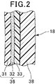
- FIG. 2 is an enlarged cross-sectional view of a cylindrical side wall portion of a double container manufactured by the double container manufacturing method of the first embodiment, taken along line II-II in FIG.
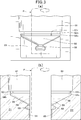
- A is the front of the bottom part of a split mold.
- B is the left side of the bottom part of the right split mold.
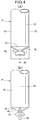
- A) is a front view of the lower part of a parison after being sandwiched between split molds.
- B is a left side view of the lower part of the parison after being sandwiched between split molds.
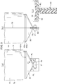
- (A) is a front view of the lower part of the parison in a state of being blown and expanded after being sandwiched between split molds.
- (B) is a left side view of the lower part of the parison in a state of being blown and expanded after being sandwiched between split molds.
- (C) is a partial cross-sectional view taken along line Vc-Vc described in (a).
- (A) is a front view of the lower part of the double container which notched the parison surplus burr
- (B) is the left view of the lower part of the double container which notched the parison surplus burr after shaping
- (C) is a fragmentary sectional view along line VIc-VIc described in (a).
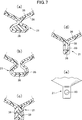
- (A) is sectional explanatory drawing of the 1st Example of the bottom protrusion part of an embodiment.
- (B) is sectional explanatory drawing of 2nd Example of the bottom protrusion part of an embodiment.
- (C) is sectional explanatory drawing of 3rd Example of the bottom protrusion part of an embodiment.
- (D) is sectional explanatory drawing of the 4th Example of the bottom protrusion part of an embodiment.
- (E) is side explanatory drawing of the 4th Example of the bottom protrusion part of an embodiment. It is a perspective view of a buttocks.
- the double container 10 manufactured by the manufacturing method according to the embodiment of the present invention includes a mouth portion 12, a neck shoulder portion 14, a cylindrical portion 18, a bottom portion 20, a bottom protrusion portion 21, and a cap with a pump 22. 24 and a heel part 26.
- the double container 10 is made by molding a molding material supplied in the form of a parison P by blow molding.
- the parison P forming the double container 10 can be easily estimated from the enlarged cross-sectional view of the cylindrical portion 18 of FIG. 2 from the inside, such as a low density polyethylene (LDPE) layer 31, an adhesive such as a polyolefin-based adhesive resin.
- LDPE low density polyethylene
- EVOH ethylene vinyl alcohol copolymer
- PP polypropylene
- the lower part of the split molds D1 and D2 for blow molding the parison P includes a mold cylindrical part 61 and a collar part 26 for molding the cylindrical part 18.
- a mold vent recess forming convex portion 67m for forming a vent recess 67n is formed in the mold rod mounting large diameter portion 64n.
- split molds D1 and D2 are arranged to face each other as shown in FIG. In this state, the parison P is inserted between the split molds D1, D2 as shown by imaginary lines in FIGS. 3 (a) and 3 (b).
- the parison P includes a pre-blowing cylindrical portion 70 for forming the cylindrical portion 18, a pre-blowing conical bottom portion 72 for forming the bottom portion 20, and a bottom protrusion.
- the blow front bottom protrusion 74 for forming the portion 21 and the lower parison surplus burr 60 are formed.
- the lower parison surplus burr 60 is substantially planar, and extends downward along the parting line 78 from the pre-blow cone bottom 72 through the pinch offline PL.
- the formed parison P is scraped off along the pinch offline PL.
- the part on the parting line 78 to which the parison surplus burr 60 of the bottom part 20 is attached becomes the pitching slit forming part PS.
- the flexible inner layer 36 is exposed in the central region of the bottom portion 20 and around the bottom protruding portion 21, and the flexible inner layer 36 is scraped off.
- the ends of the rigid outer layer 38 scraped off are present on both sides of the ends.
- the inner structure of the bottom protrusion 21 wraps the inner layer without any gaps.
- a space may exist inside the bottom protruding portion 21 inside the flexible inner layer 36.
- the bottom protrusion 21 has meandering portions alternately provided at the abutting portions of the split molds D1 and D2 to meander the laminated portion of the flexible inner layer 36 and the rigid outer layer 38. You may do it.
- the inside of the bottom protruding portion 21 is provided with a protruding portion at the same position of the abutting portion of the split molds D 1 and D 2, and penetrates the flexible inner layer 36 and the rigid outer layer 38.
- a hole 90 may be provided.
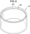
- the collar part 26 is cylindrical and has a sealed bottom. On the upper end portion of the inner surface of the collar portion 26, a collar inner circumferential projection 26b that engages with the collar mounting small diameter portion 62m is formed.
- the heel inner circumferential protrusion 26b is formed with a heel ventilation recess 26n for ventilating the inside of the ridge in cooperation with the ventilation recess 67n of the mold ridge mounting large diameter portion 64n.
- the flexible inner layer 36 and the rigid outer layer 38 at the portion where the parison surplus burrs 60 in the central region of the bottom portion 20 are scraped off are exposed.
- the flexible inner layer 36 and the rigid outer layer 38 are peeled, and a gap is formed between them.
- the bottom portion of the flexible inner container is fixed to the bottom portion of the rigid outer container by the bottom protruding portion 21, and therefore the bottom portion of the flexible inner container does not lift away from the bottom portion of the rigid outer container.
Landscapes
- Engineering & Computer Science (AREA)
- Mechanical Engineering (AREA)
- Ceramic Engineering (AREA)
- Manufacturing & Machinery (AREA)
- Containers Having Bodies Formed In One Piece (AREA)
- Blow-Moulding Or Thermoforming Of Plastics Or The Like (AREA)
- Packages (AREA)
- Containers And Packaging Bodies Having A Special Means To Remove Contents (AREA)
Abstract
Description
すなわち、一般の容器において、収容物の充填後、容器内の空間を真空にしたり、窒素ガス等の不活性ガスを充填すること等によって、充填容器を開封するまで収容物の酸化を防ぐことは容易である。しかし、一般的な剛性容器では、容器を開封して収容物を一部消費し、容器内に使用残りの収容物が残留している状態では、容器内に収容物の消費量に対応した容積の外気が入り、残留収容物が酸化する。この酸化を防ぐため、収容物に酸化防止剤を含有させることもあるが、酸化防止剤の含有は健康面等から好ましいことではない。
本発明は、比較的剛性な外容器と、該外容器内で収容物の充填量に対応して容量を変更可能な柔軟内容器とからなる二重容器の上述した問題に鑑みてなされたものである。本発明は、従来と大きく変わらない成形材料・成形装置によって容易に製造可能で、内容物が消費されて収容物が減少して柔軟性内容器の内容積が小さくなっても、内容器の底部が外容器の底部から離れて上昇することがない二重容器及びその製造方法を提供することを目的とする。
割金型によって前記パリソンの垂直方向の中間部を水平方向から挟み込んだ後にブロー成形された容器底部を有し、前記容器底部の少なくとも一部が前記割金型によって挟み込まれた部分であり、
前記容器底部が、前記容器底部の下側に、前記剛性外層容器部の外層と前記柔軟性内層容器部の外層からなる底突出部を有し、該底突出部において前記剛性外層容器部の延長部と柔軟性内層容器部の延長部が水平方向の高さが異なる凹凸を有し、該凹凸が前記剛性外層容器部の延長部と柔軟性内層容器部の延長部が互いに垂直方向にずれないように組み合っていることを特徴とする二重容器である。
割金型によって前記パリソンの垂直方向の中間部を水平方向から挟み込んだ後にブローして容器底部を成形し、前記容器底部の少なくとも一部が前記割金型によって挟み込まれた部分であり、
前記剛性外層容器部の延長部と前記柔軟性内層容器部の延長部からなる容器底部が、該容器底部より下外側の底突出部を形成し、該底突出部において前記剛性外層容器部の延長部と柔軟性内層容器部の延長部が水平方向の高さが異なる凹凸を有し、該凹凸が前記剛性外層容器部の延長部と柔軟性内層容器部の延長部が互いに垂直方向にずれないように組み合っていることを特徴とする二重容器の製造方法である。
第1発明において、前記凹凸が、前記底突出部において、前記剛性外層容器部の延長部が前記柔軟性内層容器部の延長部を包囲し、前記容器底部と前記底突出部の間にくびれ部を有して構成されている。
金型袴取付大径部64nには、通気凹部67nを形成するための金型通気凹部形成凸部67mが形成される。
しかし、底突出部21の内部は、図7(b)に示すように、柔軟性内層36の内部に空間が存在してもよい。
底突出部21の内部は、図7(c)に示すように、割金型D1,D2の突き当たり部分に互い違いに突出部を設けて、柔軟性内層36及び剛性外層38の積層部を蛇行するようにしてもよい。
さらに、底突出部21の内部は、図7(d)に示すように、割金型D1,D2の突き当たり部分の同一位置に突出部を設けて、柔軟性内層36及び剛性外層38を貫通する穴90を設けてもよい。
袴部26の底部が密封されないように構成されているときは、金型袴取付大径部64nの通気凹部67n及び袴通気凹部67mが不要であることはもちろんである。
PL ピンチオフライン
PS ピッチングスリット形成部
D1,D2 二重容器
12 口部
18 円筒部
20 底部
21 底突出部
26 袴部
36 柔軟性内層
38 剛性外層
60 パリソン余剰バリ
61 金型円筒部
62m 袴取付小径部
62n 金型袴取付小径部
64m 袴取付大径部
64n 金型袴取付大径部
66 金型円錐底部
67n 通気凹部
68 金型底突出形成部
Claims (7)
- 剛性外層容器部用の外層と柔軟性内層容器部用の内層を有するパリソンをブロー成形によって成形した二重容器であって、
割金型によって前記パリソンの垂直方向の中間部を水平方向から挟み込んだ後にブロー成形された容器底部を有し、前記容器底部の少なくとも一部が前記割金型によって挟み込まれた部分であり、
前記容器底部が、前記容器底部の下側に、前記剛性外層容器部の外層と前記柔軟性内層容器部の外層からなる底突出部を有し、該底突出部において前記剛性外層容器部の延長部と柔軟性内層容器部の延長部が水平方向の高さが異なる凹凸を有し、該凹凸が前記剛性外層容器部の延長部と柔軟性内層容器部の延長部が互いに垂直方向にずれないように組み合っていることを特徴とする二重容器。 - 前記凹凸が、前記底突出部において、前記剛性外層容器部の延長部が前記柔軟性内層容器部の延長部を包囲し、前記容器底部と前記底突出部の間にくびれ部を有して構成されている請求項1に記載の二重容器。
- 前記凹凸が、割金型の両方に形成されていて割金型合体時に突き当たる凹凸形成突部によって前記底突出部に形成された凹部を有する請求項1に記載の二重容器。
- 請求項1~3の何れか一項に記載の前記二重容器の底突出部の周囲に、袴部材を取り付けたスタンディング二重容器。
- 割金型を使用して、互いに接触して成形されかつ部分的に剥離可能な剛性外層容器部と柔軟性内層容器部とを成形する二重容器の製造方法において、
割金型によって前記パリソンの垂直方向の中間部を水平方向から挟み込んだ後にブローして容器底部を成形し、前記容器底部の少なくとも一部が前記割金型によって挟み込まれた部分であり、
前記剛性外層容器部の延長部と前記柔軟性内層容器部の延長部からなる容器底部が、該容器底部より下外側の底突出部を形成し、該底突出部において前記剛性外層容器部の延長部と柔軟性内層容器部の延長部が水平方向の高さが異なる凹凸を有し、該凹凸が前記剛性外層容器部の延長部と柔軟性内層容器部の延長部が互いに垂直方向にずれないように組み合っていることを特徴とする二重容器の製造方法。 - 前記凹凸が、前記底突出部において、前記剛性外層容器部の延長部が前記柔軟性内層容器部の延長部を包囲し、前記容器底部と前記底突出部の間にくびれ部を有するように成型する請求項5に記載の二重容器の製造方法。
- 前記凹凸が、割金型の両方に形成されて割金型合体時に突き当たる凹凸形成突部によって前記底突出部に凹部を形成する請求項5に記載の二重容器の製造方法。
Priority Applications (6)
| Application Number | Priority Date | Filing Date | Title |
|---|---|---|---|
| HK19100806.3A HK1258399B (en) | 2015-12-09 | 2016-11-15 | Double walled container and manufacturing method for same |
| EP16872767.5A EP3388351B1 (en) | 2015-12-09 | 2016-11-15 | Double walled container and manufacturing method for same |
| KR1020187019394A KR102082593B1 (ko) | 2015-12-09 | 2016-11-15 | 이중 용기 및 그 제조 방법 |
| CN201680071888.5A CN108367831B (zh) | 2015-12-09 | 2016-11-15 | 双层容器和其制造方法 |
| US16/060,175 US10954022B2 (en) | 2015-12-09 | 2016-11-15 | Double walled container |
| US16/909,472 US11427368B2 (en) | 2015-12-09 | 2020-06-23 | Manufacturing method for double walled container |
Applications Claiming Priority (2)
| Application Number | Priority Date | Filing Date | Title |
|---|---|---|---|
| JP2015-240348 | 2015-12-09 | ||
| JP2015240348A JP6737590B2 (ja) | 2015-12-09 | 2015-12-09 | 二重容器及びその製造方法 |
Related Child Applications (2)
| Application Number | Title | Priority Date | Filing Date |
|---|---|---|---|
| US16/060,175 A-371-Of-International US10954022B2 (en) | 2015-12-09 | 2016-11-15 | Double walled container |
| US16/909,472 Division US11427368B2 (en) | 2015-12-09 | 2020-06-23 | Manufacturing method for double walled container |
Publications (1)
| Publication Number | Publication Date |
|---|---|
| WO2017098867A1 true WO2017098867A1 (ja) | 2017-06-15 |
Family
ID=59013019
Family Applications (1)
| Application Number | Title | Priority Date | Filing Date |
|---|---|---|---|
| PCT/JP2016/083824 Ceased WO2017098867A1 (ja) | 2015-12-09 | 2016-11-15 | 二重容器及びその製造方法 |
Country Status (6)
| Country | Link |
|---|---|
| US (2) | US10954022B2 (ja) |
| EP (1) | EP3388351B1 (ja) |
| JP (1) | JP6737590B2 (ja) |
| KR (1) | KR102082593B1 (ja) |
| CN (1) | CN108367831B (ja) |
| WO (1) | WO2017098867A1 (ja) |
Cited By (2)
| Publication number | Priority date | Publication date | Assignee | Title |
|---|---|---|---|---|
| CN113165767A (zh) * | 2019-01-28 | 2021-07-23 | 京洛株式会社 | 收容容器及其制造方法 |
| EP3741704A4 (en) * | 2018-01-17 | 2021-10-20 | Nippon Paper Industries Co., Ltd. | REFILLABLE CONTAINER |
Families Citing this family (7)
| Publication number | Priority date | Publication date | Assignee | Title |
|---|---|---|---|---|
| CN206684414U (zh) * | 2017-02-06 | 2017-11-28 | 京东方科技集团股份有限公司 | 液晶承载器皿 |
| JP7175631B2 (ja) * | 2018-04-27 | 2022-11-21 | 株式会社吉野工業所 | 二重容器 |
| TWI658970B (zh) * | 2018-08-07 | 2019-05-11 | 臺三榮實業有限公司 | 積層剝離容器及其製法 |
| WO2020158549A1 (ja) * | 2019-01-28 | 2020-08-06 | キョーラク株式会社 | 収容容器及びその製造方法 |
| JP7524312B2 (ja) * | 2020-04-06 | 2024-07-29 | 日精エー・エス・ビー機械株式会社 | 剥離容器および剥離容器の製造方法 |
| CN114147941B (zh) * | 2021-11-30 | 2023-12-08 | 优之科技(深圳)有限公司 | 一种吹塑打磨处理系统 |
| KR102409223B1 (ko) * | 2021-12-22 | 2022-06-16 | 임종수 | 화장품 용기 및 그 제조방법 |
Citations (7)
| Publication number | Priority date | Publication date | Assignee | Title |
|---|---|---|---|---|
| JPS5745035A (en) * | 1980-08-30 | 1982-03-13 | Sekisui Chem Co Ltd | Manufacture of multilayer blown product |
| EP0532873A1 (de) * | 1991-09-18 | 1993-03-24 | GAPLAST GmbH | Behälter |
| JPH08216238A (ja) * | 1995-02-16 | 1996-08-27 | Yoshino Kogyosho Co Ltd | ブロー成形容器およびその成形用金型 |
| JP2004231280A (ja) * | 2003-01-31 | 2004-08-19 | Yoshino Kogyosho Co Ltd | 合成樹脂製容器 |
| JP2004231273A (ja) * | 2003-01-31 | 2004-08-19 | Yoshino Kogyosho Co Ltd | 合成樹脂製容器 |
| JP2006103692A (ja) * | 2004-09-30 | 2006-04-20 | Yoshino Kogyosho Co Ltd | ブロー成形容器 |
| JP2015101397A (ja) * | 2013-11-27 | 2015-06-04 | キョーラク株式会社 | 積層剥離容器 |
Family Cites Families (28)
| Publication number | Priority date | Publication date | Assignee | Title |
|---|---|---|---|---|
| US3561629A (en) * | 1969-02-17 | 1971-02-09 | Continental Can Co | Laminated or coated blow molded containers |
| JPS4936249B1 (ja) | 1969-09-16 | 1974-09-28 | ||
| US4816093A (en) * | 1987-09-25 | 1989-03-28 | Robbins Edward S Iii | Separable laminate container |
| DE69636181T2 (de) * | 1995-03-10 | 2007-03-08 | Yoshino Kogyosho Co., Ltd. | Behälter aus laminiertem, trennbarem Material |
| JP3667826B2 (ja) | 1995-08-03 | 2005-07-06 | 株式会社吉野工業所 | 積層剥離容器 |
| EP0865898B1 (en) * | 1996-05-30 | 2004-01-07 | Yoshino Kogyosho Co., Ltd. | Bottom shape of extrusion blow molded containers |
| JP3710615B2 (ja) | 1997-12-25 | 2005-10-26 | 株式会社吉野工業所 | 積層剥離容器 |
| JP3762105B2 (ja) | 1998-06-18 | 2006-04-05 | 株式会社吉野工業所 | デラミボトルとその底シール部被覆方法 |
| DE10017443A1 (de) * | 2000-04-07 | 2001-10-25 | Boehringer Ingelheim Pharma | Verfahren zum Herstellen eines mit einer Druckausgleichsöffnung versehenen Behälters und nach diesem Verfahren hergestellter Behälter |
| US6503440B2 (en) * | 2000-04-07 | 2003-01-07 | Boehringer Ingelheim Pharma Kg | Process for making a container with a pressure equalization opening and containers produced accordingly |
| JP4834260B2 (ja) * | 2000-10-05 | 2011-12-14 | キヤノン株式会社 | 液体収納容器、および該容器の製造方法 |
| JP4099961B2 (ja) * | 2001-07-19 | 2008-06-11 | 日立工機株式会社 | 遠心分離機用スイングロータ及び遠心分離機 |
| JP4147011B2 (ja) * | 2001-07-23 | 2008-09-10 | 株式会社神戸製鋼所 | スケール起因の表面疵の少ない条鋼材の製造方法 |
| CN1228217C (zh) * | 2001-08-31 | 2005-11-23 | 株式会社吉野工业所 | 注出容器 |
| EP2468642B1 (en) * | 2001-10-31 | 2015-07-22 | Yoshino Kogyosyo Co., Ltd. | Blow-molded container |
| JP3874170B2 (ja) | 2001-11-30 | 2007-01-31 | 株式会社吉野工業所 | ブロー成形容器およびその製造方法ならびに多層押出し成形用ダイス |
| JP4314423B2 (ja) | 2002-05-23 | 2009-08-19 | 株式会社吉野工業所 | ブロー成形容器 |
| CA2506145A1 (en) * | 2005-04-28 | 2006-10-28 | David Robertson | Pump bottle flow control apparatus |
| JP4936249B2 (ja) | 2007-02-28 | 2012-05-23 | 株式会社吉野工業所 | 合成樹脂製ブロー成形容器 |
| JP5267901B2 (ja) * | 2007-06-29 | 2013-08-21 | 株式会社吉野工業所 | ダイレクトブロー成形法による合成樹脂製二重容器 |
| JP5288175B2 (ja) * | 2008-11-28 | 2013-09-11 | 株式会社吉野工業所 | 合成樹脂製二重容器 |
| JP5445931B2 (ja) * | 2009-09-30 | 2014-03-19 | 株式会社吉野工業所 | 合成樹脂製ブロー成形壜体 |
| WO2011106509A1 (en) * | 2010-02-26 | 2011-09-01 | Dow Agrosciences Llc | Container |
| DE102010024980B4 (de) * | 2010-06-24 | 2012-04-26 | Gaplast Gmbh | Behälter mit Innenbeutel |
| JP6052578B2 (ja) | 2012-05-31 | 2016-12-27 | 株式会社吉野工業所 | ブロー成形容器及びブロー成型容器の製造方法 |
| BR112015023774B1 (pt) | 2013-03-15 | 2021-09-28 | Friendship Products Llc | Aparelhos de moldagem e método para formar um artigo |
| JP5295460B2 (ja) | 2013-03-26 | 2013-09-18 | キッコーマン株式会社 | 吐出容器 |
| EP3366598B1 (en) * | 2013-11-27 | 2021-01-20 | Kyoraku Co., Ltd. | Delaminatable container |
-
2015
- 2015-12-09 JP JP2015240348A patent/JP6737590B2/ja active Active
-
2016
- 2016-11-15 WO PCT/JP2016/083824 patent/WO2017098867A1/ja not_active Ceased
- 2016-11-15 EP EP16872767.5A patent/EP3388351B1/en active Active
- 2016-11-15 CN CN201680071888.5A patent/CN108367831B/zh active Active
- 2016-11-15 KR KR1020187019394A patent/KR102082593B1/ko active Active
- 2016-11-15 US US16/060,175 patent/US10954022B2/en active Active
-
2020
- 2020-06-23 US US16/909,472 patent/US11427368B2/en active Active
Patent Citations (7)
| Publication number | Priority date | Publication date | Assignee | Title |
|---|---|---|---|---|
| JPS5745035A (en) * | 1980-08-30 | 1982-03-13 | Sekisui Chem Co Ltd | Manufacture of multilayer blown product |
| EP0532873A1 (de) * | 1991-09-18 | 1993-03-24 | GAPLAST GmbH | Behälter |
| JPH08216238A (ja) * | 1995-02-16 | 1996-08-27 | Yoshino Kogyosho Co Ltd | ブロー成形容器およびその成形用金型 |
| JP2004231280A (ja) * | 2003-01-31 | 2004-08-19 | Yoshino Kogyosho Co Ltd | 合成樹脂製容器 |
| JP2004231273A (ja) * | 2003-01-31 | 2004-08-19 | Yoshino Kogyosho Co Ltd | 合成樹脂製容器 |
| JP2006103692A (ja) * | 2004-09-30 | 2006-04-20 | Yoshino Kogyosho Co Ltd | ブロー成形容器 |
| JP2015101397A (ja) * | 2013-11-27 | 2015-06-04 | キョーラク株式会社 | 積層剥離容器 |
Non-Patent Citations (1)
| Title |
|---|
| See also references of EP3388351A4 * |
Cited By (2)
| Publication number | Priority date | Publication date | Assignee | Title |
|---|---|---|---|---|
| EP3741704A4 (en) * | 2018-01-17 | 2021-10-20 | Nippon Paper Industries Co., Ltd. | REFILLABLE CONTAINER |
| CN113165767A (zh) * | 2019-01-28 | 2021-07-23 | 京洛株式会社 | 收容容器及其制造方法 |
Also Published As
| Publication number | Publication date |
|---|---|
| JP6737590B2 (ja) | 2020-08-12 |
| KR102082593B1 (ko) | 2020-02-27 |
| EP3388351B1 (en) | 2021-09-01 |
| US20200317386A1 (en) | 2020-10-08 |
| EP3388351A4 (en) | 2019-08-14 |
| US10954022B2 (en) | 2021-03-23 |
| JP2017105497A (ja) | 2017-06-15 |
| CN108367831A (zh) | 2018-08-03 |
| US11427368B2 (en) | 2022-08-30 |
| EP3388351A1 (en) | 2018-10-17 |
| KR20180093020A (ko) | 2018-08-20 |
| HK1258399A1 (zh) | 2019-11-08 |
| CN108367831B (zh) | 2021-02-02 |
| US20180354671A1 (en) | 2018-12-13 |
Similar Documents
| Publication | Publication Date | Title |
|---|---|---|
| WO2017098867A1 (ja) | 二重容器及びその製造方法 | |
| JP5937802B2 (ja) | チューブ容器 | |
| CA2962723C (en) | Delamination container | |
| US11155390B2 (en) | Coupled structure between pouring spout of refill container and pouring unit of packaging container | |
| CN107000883B (zh) | 双层容器及其制造方法 | |
| JP7706867B2 (ja) | 積層剥離容器 | |
| CN107000897B9 (zh) | 高粘性液体用双层容器 | |
| KR102227322B1 (ko) | 이중 용기 및 그 제조 방법 | |
| JP2020023352A (ja) | 二重容器 | |
| JP6807598B2 (ja) | 容器、および、容器の製造方法 | |
| JP2016141430A (ja) | 二重容器 | |
| JP4182520B2 (ja) | 注出容器 | |
| JP6025040B2 (ja) | ブロー成形容器及びブロー成形方法 | |
| JP7090977B2 (ja) | 積層剥離容器 | |
| JP2004175406A (ja) | 容器およびその減容化方法 | |
| HK1258399B (en) | Double walled container and manufacturing method for same | |
| JP2020001804A (ja) | 二重容器用キャップ、及び二重容器用キャップの製造方法 | |
| JP6656763B2 (ja) | 薄肉容器 | |
| JP2022071767A (ja) | 積層剥離容器及びこれを用いた内容物入り容器 |
Legal Events
| Date | Code | Title | Description |
|---|---|---|---|
| 121 | Ep: the epo has been informed by wipo that ep was designated in this application |
Ref document number: 16872767 Country of ref document: EP Kind code of ref document: A1 |
|
| DPE1 | Request for preliminary examination filed after expiration of 19th month from priority date (pct application filed from 20040101) | ||
| NENP | Non-entry into the national phase |
Ref country code: DE |
|
| ENP | Entry into the national phase |
Ref document number: 20187019394 Country of ref document: KR Kind code of ref document: A |
|
| WWE | Wipo information: entry into national phase |
Ref document number: 1020187019394 Country of ref document: KR |
|
| WWE | Wipo information: entry into national phase |
Ref document number: 2016872767 Country of ref document: EP |
|
| ENP | Entry into the national phase |
Ref document number: 2016872767 Country of ref document: EP Effective date: 20180709 |