WO2017104217A1 - 発泡成形品の製造方法、及び、発泡成形品 - Google Patents
発泡成形品の製造方法、及び、発泡成形品 Download PDFInfo
- Publication number
- WO2017104217A1 WO2017104217A1 PCT/JP2016/078563 JP2016078563W WO2017104217A1 WO 2017104217 A1 WO2017104217 A1 WO 2017104217A1 JP 2016078563 W JP2016078563 W JP 2016078563W WO 2017104217 A1 WO2017104217 A1 WO 2017104217A1
- Authority
- WO
- WIPO (PCT)
- Prior art keywords
- linear
- mold
- cavity
- foam
- molded product
- Prior art date
- Legal status (The legal status is an assumption and is not a legal conclusion. Google has not performed a legal analysis and makes no representation as to the accuracy of the status listed.)
- Ceased
Links
Images





Classifications
-
- B—PERFORMING OPERATIONS; TRANSPORTING
- B29—WORKING OF PLASTICS; WORKING OF SUBSTANCES IN A PLASTIC STATE IN GENERAL
- B29C—SHAPING OR JOINING OF PLASTICS; SHAPING OF MATERIAL IN A PLASTIC STATE, NOT OTHERWISE PROVIDED FOR; AFTER-TREATMENT OF THE SHAPED PRODUCTS, e.g. REPAIRING
- B29C48/00—Extrusion moulding, i.e. expressing the moulding material through a die or nozzle which imparts the desired form; Apparatus therefor
- B29C48/001—Combinations of extrusion moulding with other shaping operations
- B29C48/0012—Combinations of extrusion moulding with other shaping operations combined with shaping by internal pressure generated in the material, e.g. foaming
-
- B—PERFORMING OPERATIONS; TRANSPORTING
- B29—WORKING OF PLASTICS; WORKING OF SUBSTANCES IN A PLASTIC STATE IN GENERAL
- B29C—SHAPING OR JOINING OF PLASTICS; SHAPING OF MATERIAL IN A PLASTIC STATE, NOT OTHERWISE PROVIDED FOR; AFTER-TREATMENT OF THE SHAPED PRODUCTS, e.g. REPAIRING
- B29C44/00—Shaping by internal pressure generated in the material, e.g. swelling or foaming ; Producing porous or cellular expanded plastics articles
- B29C44/34—Auxiliary operations
- B29C44/58—Moulds
- B29C44/586—Moulds with a cavity increasing in size during foaming
-
- B—PERFORMING OPERATIONS; TRANSPORTING
- B29—WORKING OF PLASTICS; WORKING OF SUBSTANCES IN A PLASTIC STATE IN GENERAL
- B29C—SHAPING OR JOINING OF PLASTICS; SHAPING OF MATERIAL IN A PLASTIC STATE, NOT OTHERWISE PROVIDED FOR; AFTER-TREATMENT OF THE SHAPED PRODUCTS, e.g. REPAIRING
- B29C44/00—Shaping by internal pressure generated in the material, e.g. swelling or foaming ; Producing porous or cellular expanded plastics articles
- B29C44/02—Shaping by internal pressure generated in the material, e.g. swelling or foaming ; Producing porous or cellular expanded plastics articles for articles of definite length, i.e. discrete articles
- B29C44/04—Shaping by internal pressure generated in the material, e.g. swelling or foaming ; Producing porous or cellular expanded plastics articles for articles of definite length, i.e. discrete articles consisting of at least two parts of chemically or physically different materials, e.g. having different densities
-
- B—PERFORMING OPERATIONS; TRANSPORTING
- B29—WORKING OF PLASTICS; WORKING OF SUBSTANCES IN A PLASTIC STATE IN GENERAL
- B29C—SHAPING OR JOINING OF PLASTICS; SHAPING OF MATERIAL IN A PLASTIC STATE, NOT OTHERWISE PROVIDED FOR; AFTER-TREATMENT OF THE SHAPED PRODUCTS, e.g. REPAIRING
- B29C44/00—Shaping by internal pressure generated in the material, e.g. swelling or foaming ; Producing porous or cellular expanded plastics articles
- B29C44/34—Auxiliary operations
- B29C44/36—Feeding the material to be shaped
- B29C44/38—Feeding the material to be shaped into a closed space, i.e. to make articles of definite length
- B29C44/42—Feeding the material to be shaped into a closed space, i.e. to make articles of definite length using pressure difference, e.g. by injection or by vacuum
- B29C44/422—Feeding the material to be shaped into a closed space, i.e. to make articles of definite length using pressure difference, e.g. by injection or by vacuum by injecting by forward movement of the plastizising screw
-
- B—PERFORMING OPERATIONS; TRANSPORTING
- B29—WORKING OF PLASTICS; WORKING OF SUBSTANCES IN A PLASTIC STATE IN GENERAL
- B29C—SHAPING OR JOINING OF PLASTICS; SHAPING OF MATERIAL IN A PLASTIC STATE, NOT OTHERWISE PROVIDED FOR; AFTER-TREATMENT OF THE SHAPED PRODUCTS, e.g. REPAIRING
- B29C48/00—Extrusion moulding, i.e. expressing the moulding material through a die or nozzle which imparts the desired form; Apparatus therefor
- B29C48/25—Component parts, details or accessories; Auxiliary operations
- B29C48/36—Means for plasticising or homogenising the moulding material or forcing it through the nozzle or die
- B29C48/395—Means for plasticising or homogenising the moulding material or forcing it through the nozzle or die using screws surrounded by a cooperating barrel, e.g. single screw extruders
- B29C48/40—Means for plasticising or homogenising the moulding material or forcing it through the nozzle or die using screws surrounded by a cooperating barrel, e.g. single screw extruders using two or more parallel screws or at least two parallel non-intermeshing screws, e.g. twin screw extruders
-
- B—PERFORMING OPERATIONS; TRANSPORTING
- B29—WORKING OF PLASTICS; WORKING OF SUBSTANCES IN A PLASTIC STATE IN GENERAL
- B29C—SHAPING OR JOINING OF PLASTICS; SHAPING OF MATERIAL IN A PLASTIC STATE, NOT OTHERWISE PROVIDED FOR; AFTER-TREATMENT OF THE SHAPED PRODUCTS, e.g. REPAIRING
- B29C48/00—Extrusion moulding, i.e. expressing the moulding material through a die or nozzle which imparts the desired form; Apparatus therefor
- B29C48/25—Component parts, details or accessories; Auxiliary operations
- B29C48/36—Means for plasticising or homogenising the moulding material or forcing it through the nozzle or die
- B29C48/395—Means for plasticising or homogenising the moulding material or forcing it through the nozzle or die using screws surrounded by a cooperating barrel, e.g. single screw extruders
- B29C48/40—Means for plasticising or homogenising the moulding material or forcing it through the nozzle or die using screws surrounded by a cooperating barrel, e.g. single screw extruders using two or more parallel screws or at least two parallel non-intermeshing screws, e.g. twin screw extruders
- B29C48/425—Means for plasticising or homogenising the moulding material or forcing it through the nozzle or die using screws surrounded by a cooperating barrel, e.g. single screw extruders using two or more parallel screws or at least two parallel non-intermeshing screws, e.g. twin screw extruders using three or more screws
-
- B—PERFORMING OPERATIONS; TRANSPORTING
- B65—CONVEYING; PACKING; STORING; HANDLING THIN OR FILAMENTARY MATERIAL
- B65D—CONTAINERS FOR STORAGE OR TRANSPORT OF ARTICLES OR MATERIALS, e.g. BAGS, BARRELS, BOTTLES, BOXES, CANS, CARTONS, CRATES, DRUMS, JARS, TANKS, HOPPERS, FORWARDING CONTAINERS; ACCESSORIES, CLOSURES, OR FITTINGS THEREFOR; PACKAGING ELEMENTS; PACKAGES
- B65D1/00—Rigid or semi-rigid containers having bodies formed in one piece, e.g. by casting metallic material, by moulding plastics, by blowing vitreous material, by throwing ceramic material, by moulding pulped fibrous material or by deep-drawing operations performed on sheet material
- B65D1/40—Details of walls
-
- B—PERFORMING OPERATIONS; TRANSPORTING
- B29—WORKING OF PLASTICS; WORKING OF SUBSTANCES IN A PLASTIC STATE IN GENERAL
- B29C—SHAPING OR JOINING OF PLASTICS; SHAPING OF MATERIAL IN A PLASTIC STATE, NOT OTHERWISE PROVIDED FOR; AFTER-TREATMENT OF THE SHAPED PRODUCTS, e.g. REPAIRING
- B29C33/00—Moulds or cores; Details thereof or accessories therefor
- B29C33/42—Moulds or cores; Details thereof or accessories therefor characterised by the shape of the moulding surface, e.g. ribs or grooves
-
- B—PERFORMING OPERATIONS; TRANSPORTING
- B29—WORKING OF PLASTICS; WORKING OF SUBSTANCES IN A PLASTIC STATE IN GENERAL
- B29K—INDEXING SCHEME ASSOCIATED WITH SUBCLASSES B29B, B29C OR B29D, RELATING TO MOULDING MATERIALS OR TO MATERIALS FOR MOULDS, REINFORCEMENTS, FILLERS OR PREFORMED PARTS, e.g. INSERTS
- B29K2105/00—Condition, form or state of moulded material or of the material to be shaped
- B29K2105/04—Condition, form or state of moulded material or of the material to be shaped cellular or porous
- B29K2105/043—Skinned foam
-
- B—PERFORMING OPERATIONS; TRANSPORTING
- B29—WORKING OF PLASTICS; WORKING OF SUBSTANCES IN A PLASTIC STATE IN GENERAL
- B29L—INDEXING SCHEME ASSOCIATED WITH SUBCLASS B29C, RELATING TO PARTICULAR ARTICLES
- B29L2031/00—Other particular articles
- B29L2031/712—Containers; Packaging elements or accessories, Packages
- B29L2031/7132—Bowls, Cups, Glasses
Definitions
- the present invention relates to a method for producing a foam molded article and a foam molded article.
- Foamed molded products have features such as being lightweight, reducing the amount of materials used, and being excellent in heat insulation, so they are used in various applications such as food containers, daily necessities, and household appliances. It has been.
- a foam-molded article can be produced by molding a resin composition filled in a mold while foaming.
- foaming methods include, for example, a method of decomposing a foaming agent in a resin composition and a method of injecting a gas into the resin composition. In recent years, a supercritical fluid is injected into the resin composition. A way to do this is also being considered.
- injection molding for molding the resin composition.
- Such a method for producing a foam-molded product is disclosed in, for example, Patent Documents 1 to 3.
- a foamed molded product intended for heat insulation is preferred to have a small area occupied by a non-foamed portion in the molded product, but the strength and heat resistance are reduced.
- a foamed molded product that is foamed by reversing a part of the mold (core back) using injection molding has a non-foamed layer (skin layer) formed on the transfer surface of the mold. Has a sandwiched structure. For this reason, a foam molded product using injection molding has a relatively high strength and heat resistance as a foam molded product because the proportion of non-foamed portions in the molded product is large.
- the foamed molded product by injection molding has a small proportion of the foamed layer in the molded product, the heat insulating property is insufficient as a foamed molded product for heat insulation.
- As a method for improving the heat insulation of a foam molded article using injection molding it is conceivable to increase the thickness of the foam molded article.
- the amount of materials used increases and the injection molding machine needs to be enlarged. Therefore, there is a concern about an increase in manufacturing cost. Therefore, there has been a demand for a method for manufacturing a container having excellent heat insulation properties while suppressing manufacturing costs.
- control of foaming is important, and for example, it is required to uniformly generate fine bubbles in the resin composition. It is very difficult to control foaming when trying to reduce the thickness of the foamed molded product due to lightness and reduction of material usage, etc., and it is difficult to control foaming.
- the difference in the timing of solidification of the molten resin in the mold cavity increases, resulting in a problem that the smoothness of the surface of the molded product is impaired and wrinkles are formed on the surface of the foamed molded product.
- An object of the present invention is to provide a method for producing a foam-molded product, which can produce a foam-molded product excellent in the above-mentioned.
- the present inventors move the movable part of the mold to enlarge the volume of the cavity before the molten resin filled in the cavity in the mold is solidified.
- the inventors of the present invention have studied to increase the thickness of the molded product by increasing the core back amount without increasing the amount of material used in order to improve the heat insulation. It has been found that appearance problems such as deterioration and dimensional accuracy decrease and swelling on the surface of the molded product occur. Therefore, attention has been focused on improving the heat insulating property by arranging the thick portions regularly on the surface of the molded product, rather than increasing the thickness of the entire molded product. And it has been found that a foam molded article having excellent heat insulation properties can be obtained without increasing the amount of material used by providing the mold with a wide cavity portion and a narrow cavity portion.
- the present inventors examined the occurrence of blisters and wrinkles on the surface of the molded product.
- the thickness of the molded product was reduced, the fluidity of the molten resin in the cavity decreased, and gravity and a slight mold It turned out that the influence by the difference in surface roughness tends to appear.
- the inventors of the present invention provide a mold in which a first linear portion having a large space between the cavities and a space having a small space between the cavities are formed along a direction from the resin injection port toward the end of the cavity.
- a decrease in fluidity of the molten resin in the cavity can be suppressed.
- the fluidity of the molten resin in the cavity is improved, and even if a part of the molded product has a thin-walled portion, it is possible to suppress the occurrence of surface swelling and wrinkles without increasing the amount of material used.
- the inventors have found that a foam-molded article excellent in heat insulation can be produced, and completed the present invention.
- the method for producing a foam molded article of the present invention includes a step of injection molding a molten resin containing a supercritical fluid or a chemical foaming agent, and filling the cavity in a mold having a movable part, and filling the cavity. Before the molten resin finishes solidifying, and moving the movable part to expand the volume of the cavity, and the mold is along the direction from the resin injection port toward the end of the cavity.
- the first linear portions having a large gap between the cavities and the second linear portions having a small gap between the cavities are alternately arranged.
- the first linear portion is formed by a linear recess provided on the surface of the mold facing the cavity, and the second linear portion faces the cavity of the mold.
- it is formed by a linear convex portion provided on the surface.
- the height from the bottom of the linear concave portion to the top of the linear convex portion is preferably 0.1 mm or more.
- Ha and Hb satisfy Ha> Hb and 0.2 mm. As mentioned above, it is preferable that it is 3.0 mm or less.
- the Ha is preferably 0.4 mm or more and 3.0 mm or less, and the Hb is preferably 0.2 mm or more and 1.5 mm or less.
- the foamed molded product of the present invention is a foamed molded product of a resin composition, and alternately has thin and thick portions on the front and back surfaces, and the thin and thick portions are formed from a resin injection port. It is formed along the direction toward the end of the container.
- the foamed molded article of the present invention has high strength and heat resistance, suppresses the occurrence of surface swelling and wrinkles, and has excellent heat insulation properties.
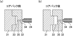
- FIG. 2 is a schematic cross-sectional view showing an enlargement of the cavity periphery of the mold of FIG. 1 in order to explain the core back, where (a) shows the initial state before the core back, and (b) shows the state after the core back. Indicates the extended state.
- It is a cross-sectional schematic diagram at the time of providing a linear recessed part and a linear convex part in one side of a metal mold
- FIG. 12 is a schematic sectional view taken along line aa of the mold shown in FIG. 11. It is the perspective view which showed typically an example of the foaming molded product manufactured with the metal mold
- FIG. 14 is a schematic cross-sectional view showing an enlarged part of a cross section taken along the line bb of the foam molded article shown in FIG. 13. It is the plane schematic diagram which showed an example of the foaming molded product manufactured with the metal mold
- FIG. 16 is a schematic cross-sectional view taken along the line cc of the foam molded product illustrated in FIG. 15.
- the method for producing a foam molded article of the present invention includes a step of injection molding a molten resin containing a supercritical fluid or a chemical foaming agent, and filling the cavity in a mold having a movable part, and filling the cavity. Before the molten resin finishes solidifying, and moving the movable part to expand the volume of the cavity, and the mold is along the direction from the resin injection port toward the end of the cavity.
- the first linear portions having a large gap between the cavities and the second linear portions having a small gap between the cavities are alternately arranged.
- a foamed molded article is manufactured by injection molding a molten resin containing a supercritical fluid or a chemical foaming agent.
- the molten resin containing the supercritical fluid include those obtained by melting the resin composition and impregnating the resin composition with the supercritical fluid, and single-phase dissolution of the resin composition and the supercritical fluid. It is preferable that it is a thing.
- the molten resin containing the supercritical fluid can be produced by injecting a supercritical fluid generated by a conventionally known supercritical fluid generator into the molten resin composition under high pressure and further stirring.
- a supercritical fluid for example, a supercritical fluid of an inert gas such as carbon dioxide, nitrogen, argon, or helium is used. Of these, carbon dioxide or nitrogen supercritical fluid is preferable, and nitrogen supercritical fluid is more preferable.
- the resin composition will be described in detail later.
- the chemical foaming agent is decomposed by heating or the like to generate a gas such as carbon dioxide.
- the chemical foaming agent include inorganic chemical foaming agents such as sodium bicarbonate and ammonium carbonate; and organic chemical foaming agents such as azodicarbonamide and N, N′-dinitrosopentatetramine.
- an inorganic chemical foaming agent is preferable because a normal injection molding machine can be used and uniform fine bubbles are easily obtained.
- a foaming aid such as an organic acid such as citric acid may be added as necessary in order to stably and uniformly make the bubbles of the foam molded product.
- the content of the chemical foaming agent with respect to the entire resin composition is preferably 1% by weight or more and 10% by weight or less.
- a supercritical fluid or a molten resin containing a chemical foaming agent is filled in the cavity of the mold, and then cooled and solidified, so that a precise shape corresponding to the shape of the cavity in the mold,
- molded products having various shapes can be manufactured.
- the supercritical fluid undergoes a phase transition to the gas, so that the molten resin is foamed and a foamed molded product containing fine bubbles is obtained. .
- the amount of bubbles can be increased by allowing a large number of foaming origins (foaming nuclei) to exist uniformly in the molten resin.
- a step of moving the movable part of the mold and expanding the volume of the cavity (hereinafter also referred to as “core back”) is performed.
- core back By forcibly expanding the cavity in a state where a part or all of the molten resin is melted, a rapid pressure decrease is caused and the amount of foaming can be greatly increased. Thereby, a bubble can be formed over the whole inside of the molten resin with which the cavity was filled.
- the mold usually has a male mold having a convex shape and a female mold having a concave shape, and a gap formed in a state where the male mold and the female mold are fitted becomes a cavity filled with a molten resin. .
- the male mold and / or the female mold When enlarging the volume of the cavity, at least a part of the male mold and / or the female mold is moved. When the male mold is the movable side and the female mold is the fixed side, the entire male mold is moved. It is preferable to move to enlarge the volume of the cavity.
- the core back is preferably started immediately after the filling of the molten resin into the cavity (0 seconds after completion of filling) to within 5 seconds after completion of filling.
- the moving speed of the mold (core back speed) is preferably 0.1 mm / second or more.
- the amount of expansion of the gap distance of the mold due to the core back (core back amount) is preferably 0.5 mm to 10 mm.
- the production of the molten resin containing the supercritical fluid and the molding while foaming the molten resin are performed using, for example, a supercritical injection molding apparatus in which an injection molding machine and a supercritical fluid generator are connected. be able to.
- a supercritical injection molding apparatus examples include a MuCell injection molding machine (“MuCell” is a registered trademark of Trexel.co. Ltd).
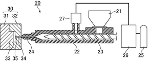
- FIG. 1 is a schematic view for explaining an example of a method for producing a foam molded article using a supercritical injection molding apparatus.
- a supercritical machine including a cylinder 25, a supercritical fluid generator 26, and an injection controller 27 in an injection molding machine including a hopper 21, a heating cylinder 22, a screw 23, and a nozzle 24.
- a fluid generator is connected.
- the hopper 21 includes a container for storing the charged resin material, and an appropriate amount of the resin material is dropped into the heating cylinder 22 through an openable opening at the bottom of the container.
- the resin material charged into the hopper 21 include pellets of a resin composition prepared by melt-kneading a mixture of a plurality of raw materials using an extruder.
- the extruder is not particularly limited, and various types of single-screw or multi-screw extruders can be used. For example, a twin-screw extruder having a set temperature of 200 ° C. or higher is preferable.
- all the raw materials may be kneaded at once, or after kneading any raw material, the remaining raw materials may be added and kneaded.
- the heating cylinder 22 can heat the inside of the cylindrical space and can melt the resin material.
- the cylinder 25 is filled with an inert gas serving as a raw material for the supercritical fluid.
- the inert gas is sent from the cylinder 25 to the supercritical fluid generator 26 and becomes a supercritical fluid.
- the supercritical fluid is introduced into the heating cylinder 22 from the supercritical fluid generator 26 via the injection controller 27.
- the injection control unit 27 controls the filling amount of the supercritical fluid into the resin material melted in the heating cylinder 22.
- the screw 23 is configured to be movable while rotating in the heating cylinder 22 and pushes it toward the tip of the heating cylinder 22 while mixing the molten resin material and the supercritical fluid. By this mixing, a single-phase melt of molten resin material and supercritical fluid (molten resin containing supercritical fluid) is formed. The molten resin containing the supercritical fluid is pushed out by the screw 23, conveyed to the nozzle 24 side, and injected from the nozzle 24 into the mold 30 by an appropriate amount.
- a foamed molded product can be produced using the injection molding machine without using the supercritical fluid generator.
- a resin composition pellet containing a chemical foaming agent is charged into the hopper 21 and melted by the heating cylinder 22 to produce a molten resin.
- the chemical foaming agent is decomposed in the heating cylinder 22 to generate carbon dioxide gas or the like.
- the molten resin is pushed out by the screw 23 and conveyed to the nozzle 24 side, and is injected from the nozzle 24 into the mold 30 by an appropriate amount.
- the mold 30 may include a first mold part and a second mold part that are opposed to each other with the cavity interposed therebetween.
- the first mold part is, for example, a male mold 31 having a convex shape
- the second mold part is, for example, a female mold 32 having a concave shape.
- a cavity 33 is formed between the male mold 31 and the female mold 32.
- the molten resin injected from the nozzle 24 passes through the runner 34 and is filled into the cavity 33 from the resin injection port 35.
- a molten resin containing a supercritical fluid due to pressure loss in the mold 30, the supercritical fluid undergoes a phase transition to a gas when the critical pressure is reached, and bubbles are generated in the molten resin. Become.
- a molten resin containing a chemical foaming agent is used, the volume of carbon dioxide gas generated in the molten resin increases due to pressure loss in the mold 30 and foams.
- FIG. 2 is a schematic cross-sectional view showing the periphery of the cavity of the mold in FIG. 1 in order to explain the core back, (a) shows the initial state before the core back, (b) The expanded state after the core back is shown.
- first linear portions having a large interval between the cavities and second linear portions having a small interval between the cavities are alternately arranged along a direction from the resin injection port toward the end of the cavity. Is done.
- the molten resin can be removed from the cavities without reducing the fluidity of the molten resin even when the thickness of the foam molded product is reduced. It can be distributed to the end.
- the first linear portion and the second linear portion along the direction from the resin injection port toward the end of the cavity, the molten resin is contained in the cavity 33, and Since it flows along the first linear portion and the second linear portion, it can flow more easily to the end of the mold.
- the first linear portion and the second linear portion only need to be along the direction from the resin injection port 35 toward the end of the cavity 33, and in a part from the resin injection port 35 to the end of the cavity 33. It may be provided.
- the first linear portion is formed by a linear recess 36 provided on the surface facing the cavity 33 of the mold 30, and the second linear portion is formed in the cavity 33 of the mold 30. It is preferable to form by the linear convex part 37 provided in the surface to face.
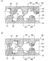
- FIG. 3 is a schematic cross-sectional view when a linear concave portion and a linear convex portion are provided on one of the molds. As shown in FIG. 3A, for example, linear concave portions 36 and linear convex portions 37 may be alternately provided on the surface of the female mold 32 facing the cavity 33. As shown in FIGS. 3B and 3C, for example, the linear concave portion 36 and the linear convex portion 37 are spaced from each other on the surface of the female mold 32 facing the cavity 33.
- the first linear portion is formed by a linear recess 36 provided in the female mold 32 and the surface of the flat male mold 31, and the second line
- the shaped portion is formed by a linear convex portion 37 provided on the female mold 32 and a flat surface of the male mold 31.
- the first linear portion is formed by a linear recess 36 provided on the surface facing the cavity 33 of the mold 30, and the second linear portion is formed in the cavity 33 of the mold 30. It is preferably formed by a linear flat portion 38 provided on the facing surface.
- FIG. 4 is a schematic cross-sectional view when a linear recess is provided on one of the molds. As shown in FIG. 4, for example, a linear recess 36 may be continuously provided on the surface of the male mold 31 facing the cavity 33.
- the first linear portion is formed by a linear recess 36 provided in the male die 31 and the surface of the flat female die 32, and the second linear portion is provided in the male die 31.
- the linear flat portion 38 and the flat female mold 32 are formed.
- the linear flat portion 38 is formed between two adjacent linear concave portions 36 when, for example, a plurality of linear concave portions 36 are formed on the surface of the mold with a certain interval therebetween. .
- the first linear portion is formed by a linear flat portion 38 provided on the surface facing the cavity 33 of the mold 30, and the second linear portion is the cavity 33 of the mold 30.
- it is formed by linear protrusions 37 provided on the surface facing the surface.
- FIG. 5 is a schematic cross-sectional view when a linear protrusion is provided on one of the molds.
- linear convex portions 37 may be continuously provided on the surface of the male mold 31 facing the cavity 33.
- the first linear portion is formed by a linear flat portion 38 provided on the male die 31 and the surface of the flat female die 32, and the second linear portion is formed on the male die 31. It is formed by the surface of the provided linear protrusion 37 and the flat female die 32.
- the linear flat portion 38 is formed between, for example, two adjacent linear convex portions 37 when a plurality of linear convex portions 37 are formed at a predetermined interval on the surface of the mold. Is done.
- the linear concave portion 36, the linear convex portion 37, and the linear flat portion 38 shown in FIGS. 3 to 5 may be provided in the male die 31 or the female die 32. Further, the linear concave portion 36, the linear convex portion 37, and the linear flat portion 38 are at least the first mold portion (male mold 31) and the second mold portion (female mold 32) of the mold 30. What is necessary is just to be provided in the surface which faces one cavity 33, and may be provided in the surface which faces the cavity 33 of both the 1st metal mold
- FIG. 6 is a schematic cross-sectional view when a linear concave portion and a linear convex portion are provided on both molds.
- the first mold part and the second mold part shift the position of the bottom part of the linear concave part 36 and the position of the top part of the linear convex part 37. May be provided.
- the first mold part and the second mold part are the position of the bottom part of the linear concave part 36 and the position of the top part of the linear convex part 37. And may be provided so as to match.
- the first linear portion is formed by a linear recess 36 provided in the male mold 31 and a linear recess 36 provided in the female mold 32.
- the second linear portion is formed by a linear convex portion 37 provided on the male mold 31 and a linear convex portion 37 provided on the female mold 32.
- the cross-sectional shape of the linear concave portion 36 on the surface orthogonal to the extending direction of the linear concave portion 36 and the cross-sectional shape of the linear convex portion 37 on the surface orthogonal to the extending direction of the linear convex portion 37 are As shown in FIGS. 3 to 6, it may be composed of a curve such as a semicircular shape or an arc shape, or may be composed of a straight line such as a polygon such as a triangle or a quadrangle. It may be.
- the gap distance of the mold 30 defines the thickness of the foam molded product.
- the molten resin cannot be sufficiently foamed, and a non-foamed portion free of bubbles may be formed.
- the non-foamed portion there is no heat insulation effect due to air bubbles, and therefore sufficient heat insulation cannot be obtained.
- the appearance of the unmolded foamed molded article 100 usually appears white due to light scattering by the bubbles, but the non-foamed part is translucent or the whiteness is low, so no foaming occurs.
- the portion is formed, the appearance of the foam molded article 100 becomes non-uniform.
- the gap distance between the molds is preferably 3 mm or less.
- the gap distance between the molds exceeds 3 mm, the cooling and solidification time becomes long. Therefore, the operation of taking out the molded product from the mold 30 and the foaming residue (foaming power remains and the resin is not sufficiently solidified.
- the foamed molded product 100 may be deformed by a portion in a state of being unfavorable, and foaming of the molten resin is relatively likely to occur, so that the advantage of employing the mold configuration of the present invention is reduced. Therefore, when the interval between the cavities in the first linear portion is Ha and the interval between the cavities in the second linear portion is Hb, Ha and Hb satisfy Ha> Hb, and 0 It is preferably 2 mm or more and 3.0 mm or less.
- A is the maximum value of the gap distance of the mold 30 in the cavity 33 before the core back.
- B is the minimum value of the gap distance of the mold 30 in the cavity 33 before the core back.
- the A is preferably 0.4 mm or more and 3.0 mm or less, and the B is preferably 0.2 mm or more and 1.5 mm or less. That is, the Ha is 0.4 mm or more and 3.0 mm or less, and the Hb is more preferably 0.2 mm or more and 1.5 mm or less.
- FIG. 7 is a schematic cross-sectional view of the mold when the cavity spacing is constant. As shown in FIG. 7A, even if neither of the first mold part 331 and the second mold part 332 of the mold 330 has a linear portion, ), Even when both of the first mold part 331 and the second mold part 332 of the mold 330 have linear portions, the interval between the cavities indicated by the double arrows is constant. And the foaming molding which has sufficient heat insulation cannot be obtained.
- the cross-sectional area of the linear concave portion 36 and the cross-sectional area of the linear convex portion 37 in the cross section orthogonal to the extending direction of the linear concave portion 36 and the linear convex portion 37 are preferably equal. By doing in this way, the container excellent in heat insulation can be manufactured, without increasing the usage-amount of material, and impairing the fluidity
- the cross-sectional area of the linear recess 36 means an average value of the cross-sectional areas of the plurality of linear recesses 36 when a plurality of linear recesses 36 are provided.
- the cross-sectional area of the linear protrusions 37 means an average value of the cross-sectional areas of the plurality of linear protrusions 37 when a plurality of linear protrusions 37 are provided. “The cross-sectional area of the linear concave portion is equal to the cross-sectional area of the linear convex portion” means that the cross-sectional area of the linear concave portion is equal to the cross-sectional area of the linear concave portion in addition to the case where both the cross-sectional areas completely match. This includes cases where the cross-sectional area is within a range of ⁇ 10%.
- L 31 is a reference line for the male mold 31, and L 32 is a reference line for the female mold 32.
- the reference lines L31 and L32 are The center line connecting the midpoint of the distance from the bottom of the recess to the top of the projection.
- the reference line L32 is a line connecting the flat portion surfaces. It is. It is preferable that the cross-sectional area of the linear concave portion 36 and the cross-sectional area of the linear convex portion 37 have an area equal to line symmetry with respect to the reference line.
- the cross-sectional area of the linear concave portion 36 and the cross-sectional area of the linear convex portion 37 are: For example, it can be calculated by the following method.
- the cross-sectional area of the linear recess 36 is, for example, between the distance H1 from the center line shown in FIG. 3 to the bottom of the linear recess 36 and the intersection of the center line and both ends of the linear recess 36. It can be calculated from the distance W1.
- the cross-sectional area of the linear protrusion 37 is, for example, the distance H2 from the center line shown in FIG.
- H1 ′, W1 ′, H2 ′, and W2 ′ of the male mold 31 correspond to H1, W1, H2, and W2 of the female mold 32, respectively.
- H1 ′, W1 ′, H2 ′, and W2 ′ of the male mold 31 are preferably the same as H1, W1, H2, and W2 of the female mold 32, respectively.
- Said H1, W1, H1 ', and W1' say the average value in the some linear recessed part 36, when the several linear recessed part 36 is provided.
- H2, W2, H2 ′, and W2 ′ are the average values of the plurality of linear protrusions 37 when a plurality of linear protrusions 37 are provided.
- cross-sectional shape of the linear concave portion 36 and the cross-sectional shape of the linear convex portion 37 are polygons such as a shape having a radius R other than a semicircle, a triangle, a quadrangle, etc.
- a reference line connecting the midpoint of the distance from the bottom of the recess to the top of the projection is set.
- the cross-sectional area of the linear concave portion 36 and the cross-sectional area of the linear convex portion 37 can be calculated using the set reference line as a reference.
- C represents the height from the bottom of the linear concave portion to the top of the linear convex portion.
- C ′ of the male mold 31 corresponds to C of the female mold 32.
- the heights C and C ′ from the bottom of the linear concave portion 36 to the top of the linear convex portion 37 are 0. It is preferable that it is 1 mm or more.
- the height is less than 0.1 mm, the fluidity of the molten resin is reduced, and the molten resin may not reach the end of the cavity.
- a preferable upper limit of the height is 1.5 mm.
- the height exceeds 1.5 mm, the difference in resin fluidity between the concave portion and the convex portion becomes large, and welds may occur near the convex portion.
- C and C ′ may be the same or different.
- the overall shape of the mold 30 can be changed according to the shape of the foam molded product.
- Examples of the shape of the foam molded product include a plate shape and a container shape.
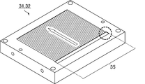
- FIG. 8 is a perspective view schematically showing a mold for producing a plate-like foam molded product.
- FIG. 9 is an enlarged schematic view of a portion surrounded by a dotted line in FIG.
- FIG. 10 is a perspective view schematically showing a mold for producing a container-like foamed molded product.
- FIG. 11 is a schematic plan view of the mold shown in FIG. 10, and
- FIG. 12 is a schematic cross-sectional view of the mold shown in FIG. 8, 10, and 11 indicate the extending direction of the linear concave portion 36 and the linear convex portion 37.
- a mold in which the resin injection port is a film gate can be used.
- the molten resin filled from the resin injection port 35 extends along the linear concave portion 36 and the linear convex portion 37. Flows linearly.
- a mold in which a resin injection port is a pin gate can be used.
- the molten resin filled from the resin injection port 35 extends along the linear concave portion 36 and the linear convex portion 37. Flows radially.
- a foam molded product having alternately thin and thick portions on the front and back surfaces can be produced.
- the foamed molded product of the present invention is a foamed molded product of a resin composition, which has alternately thick and thin portions on the front and back surfaces, and the thick and thin portions are resin injection ports. It is formed along the direction from the container toward the end of the container.
- FIG. 13 is a perspective view schematically showing an example of a foam-molded product manufactured by the mold shown in FIG.
- FIG. 14 is a schematic cross-sectional view showing an enlarged part of the cross section taken along the line bb of the foam molded article shown in FIG. As shown in FIG.
- the foam molded product 100 has thin portions 136 and thick portions 137 alternately on the front and back surfaces.
- the foam-molded article 100 is manufactured using a mold 30 in which only a female mold 32 is provided with a linear concave portion 36 and a linear convex portion 37 as shown in FIG. Even when the linear concave portion 36 and the linear convex portion 37 are provided on one side of the mold, the foamed molded product 100 obtained by foaming with the core back has the thin-walled portion 136 on the front surface and the back surface. And thick portions 137 are alternately provided. According to the present invention, even if the wall thickness is reduced, it is possible to suppress the occurrence of surface swelling and wrinkles. Therefore, it is possible to manufacture a foam molded article 100 that is lighter and more excellent in heat insulation than conventional ones.
- the cross section of the foam molded article 100 has a structure in which the foam layer 120 is sandwiched between skin layers (outer skin layers) 110 located on the surface, as shown in FIG.
- the foam layer 120 refers to a region including a large number of bubbles (foamed particles) in the resin
- the skin layer 110 refers to a region not including bubbles.
- the foam molded article 100 has a high strength due to the presence of the skin layer 110 on the surface, and the surface thereof is smooth.
- the foam molded article 100 is excellent in heat resistance because the foam layer 120 is present in the central portion, so that not only the weight can be reduced but also heat cannot be transmitted.
- the foam molded article 100 shown in FIG. 14 is an example of a foam molded article manufactured according to the present invention.
- the structure of the foam molded article manufactured according to the present invention is not limited to the three-layer structure of skin layer 110 / foam layer 120 / skin layer 110.
- the foamed layer 120 preferably has 100 or more foamed particles in the range of 1 mm ⁇ 1 mm of the foamed layer 120 when the cross section of the foamed molded product 100 is observed, and an average of 100 arbitrarily selected foamed particles.
- the particle diameter is preferably 100 ⁇ m or less.
- SEM scanning electron microscope
- the foam molded article 100 may be decorated with a pattern, color, or character on its surface.
- the use of the foam molded article 100 produced according to the present invention is not particularly limited, but is excellent in heat resistance and heat insulation and lightweight, and can be used, for example, in food containers, daily necessities, household appliances, etc. Especially, it can use suitably for the container for foodstuffs.
- the heat resistance of the foamed molded product shall conform to 7.4 S2029 7.4 heat resistance test (display heat resistance temperature 120 ° C), 7.10 microwave high frequency suitability test, and 7.11 microwave oven durability test. From the above, the food container made of the foamed molded product can be used for heating or cooking with a microwave oven.
- FIG. 15 is a schematic plan view showing an example of a foam molded product manufactured with the mold shown in FIG. 16 is a schematic cross-sectional view taken along the line cc of the foam molded article shown in FIG.
- the food container 200 has thin portions 136 and thick portions 137 alternately on the front and back surfaces, and the thin portions 136 and the thick portions 137 are provided from the resin inlet 135 to the container. It is formed along the direction toward the end.
- the cross section of the food container 200 has a structure in which the foam layer 120 is sandwiched between skin layers (outer skin layers) 110 located on the surface.
- the overall shape of the food container 200 is not particularly limited, but may be hemispherical as shown in FIGS. 15 and 16, or may have a conical shape or a trapezoidal cross section.
- the thermoplastic resin composition will be described in detail below.
- the resin composition is preferably a thermoplastic resin composition.
- a mixture of polyolefin and polylactic acid is preferably used as the thermoplastic resin composition. Since polyolefin and polylactic acid are incompatible polymers that do not dissolve each other, even if mixed, they do not dissolve each other and an interface is formed. Therefore, in foaming using a supercritical fluid, the interface can be used as a foaming origin (foaming nucleus). On the other hand, in order to produce a foamed molded product that is uniformly foamed, it is required to uniformly disperse the resin composition before foaming.
- the polyolefin and polylactic acid are made compatible and the dispersibility is improved.
- a large number of fine bubbles can be uniformly present inside the foam molded product, and a foam molded product excellent in characteristics such as heat resistance, strength and light weight is manufactured. it can.
- the melt mass flow rate (MFR) of polypropylene is preferably 5 to 100 g / 10 minutes, more preferably 10 to 50 g / 10 minutes.
- the MFR of polypropylene is a numerical value measured at a temperature of 230 ° C. and a load of 21.2 N according to JIS K7210.
- the MFR of polyethylene is preferably 5 to 100 g / 10 minutes, more preferably 10 to 50 g / 10 minutes.
- the MFR of polyethylene is a value measured at a temperature of 190 ° C. and a load of 21.2 N in accordance with JIS K7210.
- the polyolefin may contain only polypropylene and / or polyethylene, but may contain other polyolefins other than polypropylene and polyethylene.
- the other polyolefin include an ⁇ -olefin homopolymer, an ethylene-propylene copolymer, an ethylene- ⁇ olefin copolymer, and a propylene- ⁇ olefin copolymer.
- the ⁇ -olefin include 1-butene, 1-pentene, 3-methyl-1-butene, 1-hexene, 3-methyl-1-pentene, 4-methyl-1-pentene, and 3-ethyl-1.
- Examples thereof include ⁇ -olefins having 4 to 12 carbon atoms such as pentene, 1-octene, 1-decene, and 1-undecene.
- the melt viscosity (220 ° C.) of the polyolefin is preferably 150 Pa ⁇ S or more and 400 Pa ⁇ S or less.
- a more preferable lower limit of the melt viscosity of the polyolefin is 200 Pa ⁇ S, and a more preferable upper limit is 300 Pa ⁇ S.
- the melt viscosity can be measured using, for example, “Flow Tester CFT-500D” manufactured by Shimadzu Corporation. Specifically, the resin to be measured is heated to a predetermined temperature and fluidized, and is pushed out of the cylinder by a piston having a predetermined surface pressure of 1 MPa through a capillary die (inner diameter ⁇ 1 mm, length 10 mm). The viscosity characteristics can be evaluated by the time taken.
- the content of the polyolefin with respect to the entire resin composition is preferably 30% by weight or more and 80% by weight or less.
- the content is less than 30% by weight, the fluidity and solidification rate of the resin composition may be lowered, and the moldability may be deteriorated.
- the content exceeds 80% by weight, the foaming property is deteriorated, the surface of the resulting foamed molded article is uneven, the appearance is impaired, and the resin composition is mixed when the resin composition and the supercritical fluid are mixed. Things may be difficult to impregnate with supercritical fluid.
- the minimum with more preferable content with respect to the whole resin composition of polyolefin is 35 weight%, and a more preferable upper limit is 70 weight%.
- the polylactic acid is a homopolymer of L-lactic acid, a homopolymer of D-lactic acid, a copolymer of L-lactic acid and D-lactic acid, or a mixture thereof.
- the crystallinity of the polylactic acid obtained can be adjusted by the enantiomeric ratio of lactic acid, the method of copolymerizing enantiomers (random, block, graft, etc.), the method of adding a crystal nucleating agent, and the like.
- the polylactic acid preferably has a melt viscosity (220 ° C.) of 150 Pa ⁇ S or more and 400 Pa ⁇ S or less.
- a more preferable lower limit of the melt viscosity of the polylactic acid is 200 Pa ⁇ S, and a more preferable upper limit is 300 Pa ⁇ S.
- the melt viscosity of the polylactic acid can be measured in the same manner as the melt viscosity of the polyolefin.
- content with respect to the whole resin composition of the said polylactic acid is 3 to 40 weight%.
- content is less than 3% by weight, the foamability of a foamed molded product formed by foaming the resin composition may be insufficient.
- the said content exceeds 40 weight%, the fluidity
- the minimum with more preferable content with respect to the whole resin composition of the said polylactic acid is 8 weight%, and a more preferable upper limit is 30 weight%.
- the flow rate of the resin composition is adjusted by forming the polyolefin content in the range of 30% to 80% by weight and the polylactic acid content in the range of 3% to 40% by weight. Property can be improved.
- the difference in melt viscosity between the polyolefin and polylactic acid is preferably 200 Pa ⁇ S or less.
- the melt viscosity difference is 200 Pa ⁇ S or less, both components are easily mixed.
- a more preferable upper limit of the difference in melt viscosity is 150 Pa ⁇ S.
- a method of forming a chemical bond between the two components or a method of forming a cross-linked structure between the same polymers may be used.
- Foam molding using polylactic acid In the case of obtaining a product, for example, reaction extrusion (reactive processing) in which kneading is performed while synthesizing polylactic acid using a synthesis catalyst such as a metal complex, a radical generator, or the like may be used.
- a synthesis catalyst such as a metal complex, a radical generator, or the like
- the interface between polyolefin and polylactic acid acts as a foam nucleus, unlike the reaction extrusion in which kneading is performed while synthesizing polylactic acid, there is no need to add a synthesis catalyst, a radical generator or the like to the resin composition.
- tin 2-ethylhexanoate is used as a synthesis catalyst, and an antioxidant (eg, “Irganox 1010” from Ciba Specialty Chemicals) is added to form L-lactide.
- an antioxidant eg, “Irganox 1010” from Ciba Specialty Chemicals
- Method of reacting ⁇ -caprolactone Method of reacting polylactic acid and polyethylene glycol using a radical generator such as dicumyl peroxide
- PBAT polycarbonate and polybutylene adipate terephthalate
- PCL radical generator And polycaprolactone
- PBS polybutylene succinate
- PBSA polybutylene succinate adipate
- the resin composition may contain a modified polyolefin containing a carbonyl group in the molecule.
- modified polyolefin containing a carbonyl group in the molecule include those obtained by addition reaction of an unsaturated carboxylic acid, an ester of an unsaturated carboxylic acid, or an anhydride of an unsaturated carboxylic acid to the polyolefin.
- unsaturated carboxylic acid include maleic acid, fumaric acid, and itaconic acid.
- Examples of the unsaturated carboxylic acid ester include maleic acid monomethyl ester, maleic acid monoethyl ester, maleic acid diethyl ester, and fumaric acid monomethyl ester.
- Examples of the unsaturated carboxylic acid anhydride include itaconic anhydride and maleic anhydride.
- maleic anhydride-modified polyolefin, glycidyl methacrylate-modified polyolefin and the like are preferably used.
- the modified polyolefin containing a carbonyl group in the molecule may be used alone or in combination of two or more.
- the modified polyolefin containing a carbonyl group in the molecule may be a copolymer of an olefin and a vinyl monomer.
- the copolymer of olefin and vinyl monomer for example, ethylene- (meth) acrylic acid copolymer, ethylene- (meth) ethyl acrylate copolymer, and ethylene- (meth) acrylic acid methyl copolymer Etc.
- the (meth) acrylic acid may be either acrylic acid or methacrylic acid.
- the MFR of the modified polyolefin containing a carbonyl group in the molecule is preferably 0.1 to 100 g / 10 minutes, more preferably 0.3 to 50 g / 10 minutes.
- MFR is a numerical value measured at a temperature of 230 ° C. and a load of 21.2 N in accordance with JIS K7210.
- the content of the modified polyolefin containing a carbonyl group in the molecule with respect to the entire resin composition is preferably 1% by weight or more and 20% by weight or less. Within this range, an interface is formed between the incompatible polyolefin and polylactic acid, and the dispersibility of both components can be effectively improved.
- the content is less than 1% by weight, the foamability of the obtained foamed molded product may be lowered.
- the content exceeds 20% by weight, generation of odor, coloring, deterioration of moldability, increase in water absorption, and the like may be caused.
- the more preferable lower limit of the content of the modified polyolefin containing a carbonyl group in the molecule with respect to the entire resin composition is 3% by weight, and the more preferable upper limit is 12% by weight.
- the resin composition may contain a layered silicate. Addition of layered silicate improves the dispersibility of polyolefin and polylactic acid and foams into the resin composition when the shear force during mixing is insufficient by simply mixing polyolefin and polylactic acid. Nuclei can be highly dispersed.
- layered silicate examples include pyrophyllite, talc, kaolin (kaolinite), montmorillonite, fisheye stone, margarite, prenite, mica (mica) and the like, and in particular, talc, kaolin, montmorillonite, Mica (mica) is preferably used.
- the said layered silicate may be used independently and may use 2 or more types together.
- the content of the layered silicate with respect to the entire resin composition is preferably 10% by weight or more and 40% by weight or less. If the content is less than 10% by weight, the effect of improving the shearing force during mixing may not be sufficiently obtained. When the said content exceeds 40 weight%, the moldability of a resin composition may fall.
- the minimum with more preferable content with respect to the whole resin composition of the said layered silicate is 15 weight%, and a more preferable upper limit is 35 weight%.
- the resin composition may contain a filler other than the layered silicate.
- fillers composed of inorganic materials include metal oxides (magnesium oxide, calcium oxide, etc.), graphite, carbon black, molybdenum disulfide, tungsten disulfide, calcium carbonate, silica, silica gel, zeolite, boron nitride, and alumina. Etc. can be used.
- fillers composed of organic materials include fluorine resins such as polytetrafluoroethylene (PTFE), ultrahigh molecular weight polyethylene, electron beam cross-linked polyethylene, aromatic polyamide, aliphatic polyamide, silicon carbide, acrylic resin, and phenol. Resin, melamine resin, etc. can be used.
- the compounding quantity of fillers other than a layered silicate is not specifically limited, For example, it is set as the range which does not exceed 1 weight% with respect to the whole resin composition.
- Example 1 50% by weight of polypropylene, 30% by weight of polylactic acid and 20% by weight of talc were dry blended and kneaded at a temperature setting of 220 ° C. using a twin-screw extruder (manufactured by Nippon Steel Co., Ltd., “TEX30”).
- a thermoplastic resin composition for foaming was obtained.
- the obtained thermoplastic resin composition for foaming was a thermoplastic resin composition in which polylactic acid particles were dispersed in polypropylene. Table 1 below shows the sources and physical properties of each material.
- the obtained pellet-shaped foaming thermoplastic resin composition was put into an injection molding machine (manufactured by Toshiba Machine Co., Ltd.) equipped with a supercritical generator. While the thermoplastic resin composition for foaming was melted in a cylinder set at a temperature of 220 ° C., a supercritical fluid of nitrogen (N 2 ) was mixed under the conditions of a filling amount of 0.3% by weight and a filling pressure of 16 MPa. .
- the filling amount (unit: wt%) of the supercritical fluid can be calculated by the following formula (1).
- Filling amount of supercritical fluid (unit:% by weight) [(flow rate of supercritical fluid ⁇ flow time of supercritical fluid ⁇ conversion factor 27.8) ⁇ weight of thermoplastic resin composition for foaming] ⁇ 100 (1)
- the molten resin obtained by mixing the supercritical fluid was injected into the cavity in the mold under the conditions of an injection speed of 80 mm / second and a screw back pressure of 15 MPa.
- a mold as shown in FIG. 3 (a), FIG. 8 and FIG. 9, a plate-shaped foam-molded product having a linear concave portion and a linear convex portion on one side of the mold is manufactured.
- a mold that can be used was used.
- the mold temperature was 60 ° C.
- the maximum value A of the gap distance of the mold in the cavity before the core back is 0.9 mm
- the minimum value B of the gap distance of the mold in the cavity before the core back is 0.8 mm
- the linear shape of the mold The height C from the bottom of the concave portion to the top of the linear convex portion was 0.1 mm
- the distance D from the center line of one mold to the surface of the other mold was 0.85 mm.
- the distance H1 from the center line to the bottom of the linear recess was 0.05 mm
- the distance W1 between the intersections of the center line and both ends of the linear recess was 0.1 mm.
- the distance H2 from the center line to the top of the linear convex portion was 0.05 mm, and the distance W2 between the intersections of the central line and both ends of the linear convex portion was 0.1 mm.
- the cavity volume before the core back was 19.1 cm 3 .
- the core back was performed at the timing immediately after the filling of the molten resin into the cavity 33 was completed. Specifically, foaming of the molten resin was promoted by retreating the male die 31 of the mold by 1.5 mm and increasing the volume of the cavity 33. The cavity volume after the core back was 52.9 cm 3 . After the solidification of the molten resin was completed, the foamed molded product was taken out.
- the foam molded product produced in this example was a plate-shaped foam molded product having linear concave portions and linear convex portions alternately on the front and back surfaces as shown in FIG.
- the foam molded product 100 had skin layers 110 on both surfaces of the foam layer 120.
- Example 2 As shown in Table 2 below, a foam-molded article was produced in the same manner as in Example 1 except that the shape of the mold was changed. In Examples and Comparative Examples, a mold capable of producing a plate-like foamed molded product was used. In Examples 2 to 7, as in Example 1, a mold having a linear concave part and a linear convex part on one side of the mold as shown in FIG. In Example 8, a mold having a linear concave portion on one side of the mold as shown in FIG. 4 and capable of producing a plate-like foam molded product was used. In Examples 9 and 10, as shown in FIG.
- a mold having a linear concave portion and a linear convex portion was used for both of the molds (male mold and female mold).
- Example 11 a mold having linear concave portions and linear convex portions was used for both of the molds (male mold and female mold) as shown in FIG.
- Comparative Examples 1 to 8 neither the male mold nor the female mold as shown in FIG. 7A has a linear recess and a linear protrusion, and the cavity spacing A mold having a constant value was used.
- Comparative Example 9 as shown in FIG. 7B both the mold (male mold and female mold) have linear concave portions and linear convex portions, but the interval between the cavities is constant. A mold was used.
- the foaming ratio was calculated by dividing the volume per sheet of a foam-molded product molded into a plate shape (hereinafter also referred to as a foam-molded plate) by the volume of the cavity before the core back. Specifically, it was calculated by the following method. 1. A bucket and a weight with a measurement line at a predetermined position were prepared, and the total weight (g) of the bucket and the weight was measured. 2. Water was poured up to the measuring line into the bucket containing the weight, and the total weight (g) of the bucket, weight and water was measured. 3.
- the value obtained by subtracting Z from the above X was divided by 10 to calculate the volume (cm 3 ) per sheet of the foam-molded plate. 7).
- the expansion ratio of the foam-molded plate was calculated by dividing the volume per sheet of the foam-molded plate by the cavity volume (cm 3 ) before the core back.
Landscapes
- Engineering & Computer Science (AREA)
- Mechanical Engineering (AREA)
- Ceramic Engineering (AREA)
- Injection Moulding Of Plastics Or The Like (AREA)
Abstract
Description
上記樹脂組成物は、熱可塑性樹脂組成物であることが好ましい。上記熱可塑性樹脂組成物としては、例えば、ポリオレフィン及びポリ乳酸の混合物が好適に用いられる。ポリオレフィンとポリ乳酸とは互いに溶解しない非相溶系のポリマー同士であるため、混合しても互いに溶解せず、界面が形成される。したがって、超臨界流体を用いた発泡において、その界面を発泡起点(発泡核)として用いることができる。一方で、均一に発泡した発泡成形品を製造するためには、発泡させる前の樹脂組成物を均一に分散することが求められる。このため、カルボニル基を含む変性ポリオレフィンを添加することで、ポリオレフィンとポリ乳酸を相溶化し、分散性を向上させる。これにより、発泡成形品の内部に、多数の微細な気泡(粒子径の小さい発泡粒子)を均一に存在させることができ、耐熱性、強度及び軽量性等の特性に優れた発泡成形品を製造できる。
上記他のポリオレフィンとしては、例えば、α-オレフィンの単重合体、エチレン-プロピレン共重合体、エチレン-αオレフィン共重合体、及び、プロピレン-αオレフィン共重合体等が挙げられる。上記α-オレフィンとしては、例えば、1-ブテン、1-ペンテン、3-メチル-1-ブテン、1-ヘキセン、3-メチル-1-ペンテン、4-メチル-1-ペンテン、3-エチル-1-ペンテン、1-オクテン、1-デセン、及び、1-ウンデセン等の炭素数4~12のα-オレフィンが挙げられる。
ポリプロピレン50重量%、ポリ乳酸30重量%及びタルク20重量%をドライブレンドし、二軸押出機(株式会社日本製鋼所製、「TEX30」)を使って温度設定220℃で混練し、ペレット状の発泡用熱可塑性樹脂組成物を得た。得られた発泡用熱可塑性樹脂組成物は、ポリ乳酸の粒子がポリプロピレン中に分散した熱可塑性樹脂組成物であった。下記表1に、各材料の入手先及び物性を示した。

超臨界流体の充填量(単位:重量%)=[(超臨界流体の流量×超臨界流体の流入時間×換算係数27.8)÷発泡用熱可塑性樹脂組成物の重量]×100 (1)
下記表2に示したように、金型の形状を変更したこと以外は、実施例1と同様にして発泡成形品を作製した。なお、実施例及び比較例では、板状の発泡成形品を製造できる金型を用いた。実施例2~7は、実施例1と同様に、図3の(a)に示したような、金型の一方に線状の凹部及び線状の凸部を有する金型を用いた。実施例8は、図4に示したような、金型の一方に線状の凹部を有し、板状の発泡成形品を製造できる金型を用いた。実施例9及び10は、図6の(a)に示したような、金型の両方(雄型及び雌型)に、線状の凹部と線状の凸部とを有する金型を用いた。実施例11は、図6の(b)に示したような、金型の両方(雄型及び雌型)に、線状の凹部と線状の凸部とを有する金型を用いた。比較例1~8では、図7の(a)に示したような、金型の雄型及び雌型のいずれにも、線状の凹部と線状の凸部を有さず、キャビティの間隔が一定である金型を用いた。比較例9は、図7の(b)に示したような、金型の両方(雄型及び雌型)に、線状の凹部と線状の凸部とを有するが、キャビティの間隔が一定である金型を用いた。
実施例1~11及び比較例1~9で作製した発泡成形品について、以下の方法により、発泡倍率を算出し、断熱性及び外観を評価した。その結果を下記表2に示した。なお、比較例2は、コアバック前のキャビティ容積が小さいため、溶融樹脂が充分に充填できず、板状に形成することができなかったため、下記評価は実施していない。
発泡倍率は、板状に成形した発泡成形品(以下、発泡成形板ともいう)の一枚辺りの容積を、コアバック前のキャビティの容積で割ることで算出した。具体的には、以下の方法により算出した。
1.所定の位置に計量線を付けたバケツと錘を準備し、バケツと錘の総重量(g)を測定した。
2.錘を入れたバケツに、計量線まで注水し、バケツと錘と水の総重量(g)を測定した。
3.上記バケツと錘と水の総重量から、上記バケツと錘の総重量を引いた値を、水の密度(1g/cm3)で割って、発泡成形板を入れない状態での水の容積X(cm3)を算出した。
4.実施例1~11及び比較例1~9の各々について、発泡成形板十枚を準備した。発泡成形板十枚を空のバケツに入れ、その上に錘を乗せ、上記計量線まで注水し、総重量Y(g)を測定した。
5.上記Yから上記バケツと錘の総重量を引いた値を、水の密度(1g/cm3)で割って、発泡成形板を入れた状態での水の容積Z(cm3)を算出した。
6.上記Xから上記Zを引いた値を、10で割って、発泡成形板の一枚辺りの容積(cm3)を算出した。
7.上記発泡成形板の一枚辺りの容積を、コアバック前のキャビティ容積(cm3)で割って、発泡成形板の発泡倍率を算出した。
断熱ボックスの中間を発泡成形板で仕切り、体積が同じ二つの部屋を作製した。一方の部屋にヒーターと熱電対を配置し、他方の部屋には熱電対のみを配置した。その後、ヒーターで加温し、ヒーターを配置した部屋の温度と、他方の部屋の温度との差が30℃になるまでに要した時間を測定した。この時間が120分以上を〇(合格)とし、120分未満を×(不合格)とした。
実施例1~11及び比較例1~9の各々について、発泡成形品を100個ずつ準備し、それらの外観を目視で確認した。すべての発泡成形品において表面の膨れ、及び、皺が確認されなかった場合を〇(合格)とし、いずれか1個以上の発泡成形品で表面の膨れ、又は、皺が確認された場合を×(不合格)とした。

21 ホッパ
22 シリンダ
23 スクリュ
24 ノズル
25 ボンベ
26 超臨界流体発生部
27 注入制御部
30、330 金型
31、331 第一金型部(雄型)
32、332 第二金型部(雌型)
33 キャビティ
34 ランナ
35、135 樹脂注入口
36 線状の凹部
37 線状の凸部
38 線状の平坦部
100 発泡成形品
110 スキン層(外皮層)
120 発泡層
136 薄肉部
137 厚肉部
200 食品用容器
Claims (7)
- 超臨界流体、又は、化学発泡剤を含む溶融樹脂を射出成形して、可動部を有する金型内のキャビティに充填する工程と、
前記キャビティに充填された前記溶融樹脂が固化し終わる前に、前記可動部を移動させて前記キャビティの容積を拡大させる工程とを有し、
前記金型は、樹脂注入口から前記キャビティの末端に向かう方向に沿って、前記キャビティの間隔が広い第1の線状部分と前記キャビティの間隔が狭い第2の線状部分とが交互に配置されることを特徴とする発泡成形品の製造方法。 - 前記第1の線状部分は、前記金型の前記キャビティに面する表面に設けられた線状の凹部により形成され、かつ、前記第2の線状部分は、前記金型の前記キャビティに面する表面に設けられた線状の凸部により形成されることを特徴とする請求項1に記載の発泡成形品の製造方法。
- 前記線状の凹部の底部から前記線状の凸部の頂部までの高さは、0.1mm以上であることを特徴とする請求項2に記載の発泡成形品の製造方法。
- 前記第1の線状部分での前記キャビティの間隔をHa、前記第2の線状部分での前記キャビティの間隔をHbとすると、前記Ha及び前記Hbは、Ha>Hbであり、0.2mm以上、3.0mm以下であることを特徴とする請求項1~3のいずれかに記載の発泡成形品の製造方法。
- 前記Haは、0.4mm以上、3.0mm以下であり、上記Hbは、0.2mm以上、1.5mm以下であることを特徴とする請求項4に記載の発泡成形品の製造方法。
- 表面及び裏面に厚肉部と薄肉部とを交互に有する発泡成形品を製造することを特徴とする請求項1~5のいずれかに記載の発泡成形品の製造方法。
- 樹脂組成物の発泡成形品であって、
表面及び裏面に薄肉部と厚肉部とを交互に有し、
前記薄肉部と厚肉部とは、樹脂注入口から容器の末端に向かう方向に沿って形成されたことを特徴とする発泡成形品。
Priority Applications (4)
| Application Number | Priority Date | Filing Date | Title |
|---|---|---|---|
| CN201680060492.0A CN108349126B (zh) | 2015-12-15 | 2016-09-28 | 发泡成型品的制造方法和发泡成型品 |
| EP16875203.8A EP3392014B1 (en) | 2015-12-15 | 2016-09-28 | Method for manufacturing a foam molded article |
| JP2016560833A JP6085729B1 (ja) | 2015-12-15 | 2016-09-28 | 発泡成形品の製造方法、及び、発泡成形品 |
| US16/061,613 US10906216B2 (en) | 2015-12-15 | 2016-09-28 | Method for manufacturing foam molded article, and foam molded article |
Applications Claiming Priority (2)
| Application Number | Priority Date | Filing Date | Title |
|---|---|---|---|
| JP2015244343 | 2015-12-15 | ||
| JP2015-244343 | 2015-12-15 |
Publications (1)
| Publication Number | Publication Date |
|---|---|
| WO2017104217A1 true WO2017104217A1 (ja) | 2017-06-22 |
Family
ID=59056033
Family Applications (1)
| Application Number | Title | Priority Date | Filing Date |
|---|---|---|---|
| PCT/JP2016/078563 Ceased WO2017104217A1 (ja) | 2015-12-15 | 2016-09-28 | 発泡成形品の製造方法、及び、発泡成形品 |
Country Status (3)
| Country | Link |
|---|---|
| US (1) | US10906216B2 (ja) |
| CN (1) | CN108349126B (ja) |
| WO (1) | WO2017104217A1 (ja) |
Cited By (3)
| Publication number | Priority date | Publication date | Assignee | Title |
|---|---|---|---|---|
| WO2019139130A1 (ja) * | 2018-01-12 | 2019-07-18 | バンドー化学株式会社 | 発泡成形品、及び、発泡成形品の製造方法 |
| JP2021030716A (ja) * | 2019-08-29 | 2021-03-01 | 孝廣 阿部 | 凹凸状の模様を設けた金型と凹凸状の模様を設けた食器・容器。 |
| WO2022030330A1 (ja) * | 2020-08-06 | 2022-02-10 | 凸版印刷株式会社 | 射出成形体及びその製造方法並びにヒンジキャップ及びタンパーエビデンスキャップ |
Families Citing this family (6)
| Publication number | Priority date | Publication date | Assignee | Title |
|---|---|---|---|---|
| CN111286070B (zh) * | 2020-02-11 | 2021-06-29 | 中国科学院宁波材料技术与工程研究所 | 一种超临界流体注塑发泡聚乳酸泡沫材料及其制备方法 |
| JP7310666B2 (ja) * | 2020-03-16 | 2023-07-19 | トヨタ自動車株式会社 | 中子成形装置 |
| CN115091681A (zh) * | 2020-05-23 | 2022-09-23 | 侯奥 | 一种多功能发泡模具系统及其使用方法 |
| USD1100451S1 (en) | 2020-12-03 | 2025-11-04 | Puma SE | Shoe |
| USD1022420S1 (en) | 2020-12-03 | 2024-04-16 | Puma SE | Shoe |
| TW202506501A (zh) * | 2023-03-02 | 2025-02-16 | 美商星巴克股份有限公司 | 用於具有發泡底座的飲料容器之系統、方法和裝置 |
Citations (3)
| Publication number | Priority date | Publication date | Assignee | Title |
|---|---|---|---|---|
| JPH09272571A (ja) * | 1996-04-02 | 1997-10-21 | Kobayashi Kk | 断熱食品容器及びその製造方法 |
| JP2001277304A (ja) * | 2000-03-30 | 2001-10-09 | Hitachi Chem Co Ltd | 半導体ウエハ用研磨パッドの製造法 |
| JP2002019760A (ja) * | 2000-07-03 | 2002-01-23 | Fuji Seal Inc | 食品用の断熱容器 |
Family Cites Families (12)
| Publication number | Priority date | Publication date | Assignee | Title |
|---|---|---|---|---|
| JP2002067111A (ja) | 2000-08-30 | 2002-03-05 | Inoac Corp | ソリッド部分付き発泡成形品及びその製造方法 |
| JP4465929B2 (ja) | 2001-07-05 | 2010-05-26 | 株式会社プライムポリマー | 熱可塑性樹脂組成物発泡体の製造方法 |
| JP2003231148A (ja) | 2002-02-06 | 2003-08-19 | Hitachi Maxell Ltd | 熱可塑性樹脂発泡体の成形方法 |
| US8052551B2 (en) * | 2004-02-26 | 2011-11-08 | Sport Maska Inc. | Sports apparatus shaft and blade with added impact protection and method of making same |
| WO2006051794A1 (ja) | 2004-11-09 | 2006-05-18 | Prime Polymer Co., Ltd. | 射出発泡成形方法および射出発泡成形用金型 |
| JP2007210323A (ja) | 2006-01-10 | 2007-08-23 | Mazda Motor Corp | 樹脂成形品の成形方法及び成形装置 |
| DE102006008184A1 (de) | 2006-02-22 | 2007-08-23 | Demag Ergotech Gmbh | Verfahren zur Herstellung von dünnwandigen Kunststoff-Formteilen |
| JP5228197B2 (ja) | 2007-06-11 | 2013-07-03 | 株式会社 ダイサン | 薄肉成形品及び箱体 |
| US20080305339A1 (en) | 2007-06-11 | 2008-12-11 | Kabushiki Kaisha Daisan | Thin molded article |
| JP2009226872A (ja) | 2008-03-25 | 2009-10-08 | Mazda Motor Corp | 発泡樹脂成形品の成形方法及び成形装置 |
| WO2010070857A1 (ja) | 2008-12-17 | 2010-06-24 | Komatsu Michio | 発泡成形品の製造方法 |
| CA2764098C (en) | 2009-06-29 | 2013-05-14 | Michio Komatsu | Wood powder-containing resin molded article and method for producing the same |
-
2016
- 2016-09-28 CN CN201680060492.0A patent/CN108349126B/zh not_active Expired - Fee Related
- 2016-09-28 WO PCT/JP2016/078563 patent/WO2017104217A1/ja not_active Ceased
- 2016-09-28 US US16/061,613 patent/US10906216B2/en active Active
Patent Citations (3)
| Publication number | Priority date | Publication date | Assignee | Title |
|---|---|---|---|---|
| JPH09272571A (ja) * | 1996-04-02 | 1997-10-21 | Kobayashi Kk | 断熱食品容器及びその製造方法 |
| JP2001277304A (ja) * | 2000-03-30 | 2001-10-09 | Hitachi Chem Co Ltd | 半導体ウエハ用研磨パッドの製造法 |
| JP2002019760A (ja) * | 2000-07-03 | 2002-01-23 | Fuji Seal Inc | 食品用の断熱容器 |
Cited By (7)
| Publication number | Priority date | Publication date | Assignee | Title |
|---|---|---|---|---|
| WO2019139130A1 (ja) * | 2018-01-12 | 2019-07-18 | バンドー化学株式会社 | 発泡成形品、及び、発泡成形品の製造方法 |
| JP6606306B1 (ja) * | 2018-01-12 | 2019-11-13 | バンドー化学株式会社 | 発泡成形品、及び、発泡成形品の製造方法 |
| CN111565904A (zh) * | 2018-01-12 | 2020-08-21 | 阪东化学株式会社 | 发泡成型品以及发泡成型品的制造方法 |
| JP2021030716A (ja) * | 2019-08-29 | 2021-03-01 | 孝廣 阿部 | 凹凸状の模様を設けた金型と凹凸状の模様を設けた食器・容器。 |
| WO2022030330A1 (ja) * | 2020-08-06 | 2022-02-10 | 凸版印刷株式会社 | 射出成形体及びその製造方法並びにヒンジキャップ及びタンパーエビデンスキャップ |
| JP2022030088A (ja) * | 2020-08-06 | 2022-02-18 | 凸版印刷株式会社 | 射出成形体及びその製造方法並びにヒンジキャップ及びタンパーエビデンスキャップ |
| JP7494638B2 (ja) | 2020-08-06 | 2024-06-04 | Toppanホールディングス株式会社 | 射出成形体の製造方法並びにヒンジキャップ及びタンパーエビデンスキャップ |
Also Published As
| Publication number | Publication date |
|---|---|
| CN108349126A (zh) | 2018-07-31 |
| US20190344486A1 (en) | 2019-11-14 |
| CN108349126B (zh) | 2021-04-09 |
| US10906216B2 (en) | 2021-02-02 |
Similar Documents
| Publication | Publication Date | Title |
|---|---|---|
| WO2017104217A1 (ja) | 発泡成形品の製造方法、及び、発泡成形品 | |
| JP6077726B1 (ja) | 発泡成形品の製造方法 | |
| JP6043897B1 (ja) | 発泡成形品の製造方法及び発泡成形品 | |
| JP6430684B1 (ja) | 食品用容器の製造方法 | |
| JP5993108B1 (ja) | 発泡用樹脂組成物及び発泡成形体 | |
| TWI444417B (zh) | Polypropylene resin foamed beads and molded articles thereof | |
| CN1852797B (zh) | 热塑性树脂发泡性粒子的制造方法 | |
| JP2017094538A (ja) | 断熱性食品容器の製造方法 | |
| JP6606306B1 (ja) | 発泡成形品、及び、発泡成形品の製造方法 | |
| JP6085729B1 (ja) | 発泡成形品の製造方法、及び、発泡成形品 | |
| JP2020040690A (ja) | 発泡容器及び発泡容器の製造方法 | |
| JP6768251B2 (ja) | 発泡用樹脂組成物及び発泡成形体 | |
| JP2022183870A (ja) | 食品用容器 | |
| JP2023101170A (ja) | 発泡容器の製造方法 |
Legal Events
| Date | Code | Title | Description |
|---|---|---|---|
| ENP | Entry into the national phase |
Ref document number: 2016560833 Country of ref document: JP Kind code of ref document: A |
|
| 121 | Ep: the epo has been informed by wipo that ep was designated in this application |
Ref document number: 16875203 Country of ref document: EP Kind code of ref document: A1 |
|
| NENP | Non-entry into the national phase |
Ref country code: DE |
|
| WWE | Wipo information: entry into national phase |
Ref document number: 2016875203 Country of ref document: EP |
|
| ENP | Entry into the national phase |
Ref document number: 2016875203 Country of ref document: EP Effective date: 20180716 |