WO2017109831A1 - トラックのサイドスカート - Google Patents
トラックのサイドスカート Download PDFInfo
- Publication number
- WO2017109831A1 WO2017109831A1 PCT/JP2015/085670 JP2015085670W WO2017109831A1 WO 2017109831 A1 WO2017109831 A1 WO 2017109831A1 JP 2015085670 W JP2015085670 W JP 2015085670W WO 2017109831 A1 WO2017109831 A1 WO 2017109831A1
- Authority
- WO
- WIPO (PCT)
- Prior art keywords
- sheet
- truck
- fixed
- side skirt
- flap
- Prior art date
- Legal status (The legal status is an assumption and is not a legal conclusion. Google has not performed a legal analysis and makes no representation as to the accuracy of the status listed.)
- Ceased
Links
Images


Classifications
-
- B—PERFORMING OPERATIONS; TRANSPORTING
- B62—LAND VEHICLES FOR TRAVELLING OTHERWISE THAN ON RAILS
- B62D—MOTOR VEHICLES; TRAILERS
- B62D35/00—Vehicle bodies characterised by streamlining
- B62D35/001—For commercial vehicles or tractor-trailer combinations, e.g. caravans
-
- B—PERFORMING OPERATIONS; TRANSPORTING
- B60—VEHICLES IN GENERAL
- B60R—VEHICLES, VEHICLE FITTINGS, OR VEHICLE PARTS, NOT OTHERWISE PROVIDED FOR
- B60R19/00—Wheel guards; Radiator guards, e.g. grilles; Obstruction removers; Fittings damping bouncing force in collisions
- B60R19/56—Fittings damping bouncing force in truck collisions, e.g. bumpers; Arrangements on high-riding vehicles, e.g. lorries, for preventing vehicles or objects from running thereunder
-
- B—PERFORMING OPERATIONS; TRANSPORTING
- B60—VEHICLES IN GENERAL
- B60R—VEHICLES, VEHICLE FITTINGS, OR VEHICLE PARTS, NOT OTHERWISE PROVIDED FOR
- B60R19/00—Wheel guards; Radiator guards, e.g. grilles; Obstruction removers; Fittings damping bouncing force in collisions
- B60R19/56—Fittings damping bouncing force in truck collisions, e.g. bumpers; Arrangements on high-riding vehicles, e.g. lorries, for preventing vehicles or objects from running thereunder
- B60R19/565—Fittings damping bouncing force in truck collisions, e.g. bumpers; Arrangements on high-riding vehicles, e.g. lorries, for preventing vehicles or objects from running thereunder on vehicle sides
-
- B—PERFORMING OPERATIONS; TRANSPORTING
- B62—LAND VEHICLES FOR TRAVELLING OTHERWISE THAN ON RAILS
- B62D—MOTOR VEHICLES; TRAILERS
- B62D35/00—Vehicle bodies characterised by streamlining
- B62D35/008—Side spoilers
-
- B—PERFORMING OPERATIONS; TRANSPORTING
- B62—LAND VEHICLES FOR TRAVELLING OTHERWISE THAN ON RAILS
- B62D—MOTOR VEHICLES; TRAILERS
- B62D35/00—Vehicle bodies characterised by streamlining
- B62D35/02—Streamlining the undersurfaces
Definitions
- the present invention relates to a side skirt that covers the left and right sides of a track.
- a plate-shaped side guard (described in Japanese Patent Laid-Open No. 2005-161960 (Patent Document 1)) is used. Side bumper) is installed.
- an object of the present invention is to provide a side skirt of a truck that can improve the fuel efficiency of the truck while considering the maintenance work.
- a flexible rectangular sheet is attached between the cargo bed and the side guard.
- one end of the seat in the vertical direction is fixed to one of the loading platform and the side guard, and the other end of the seat in the vertical direction is detachably fixed to the other of the loading platform and the side guard.
- FIG. 1 shows an example of a track having a side guard.
- the truck 100 includes a ladder-shaped frame 120 that extends in the front-rear direction of the vehicle body, a cabin 140 that is tiltably mounted on the front portion of the frame 120, and a loading platform 160 that is fixed to the frame 120 that is located behind the cabin 140.
- a pair of left and right front wheels 180 are attached to the frame 120 located below the cabin 140 via a front suspension (not shown) so as to be steerable.
- Two pairs of left and right rear wheels 200 are attached to the frame 120 located below the loading platform 160 via a rear suspension (not shown).
- a plurality of stays 220 having, for example, an L-shape in a side view are attached to the lower surface of the loading platform 160 located between the front wheel 180 and the rear wheel 200 with a predetermined interval.
- a plurality of stays 240 having an L shape, for example, as viewed from the side, are attached to the lower surface of the loading platform 160 located behind the rear wheel 200 at a predetermined interval.
- the L-shape is not limited to a complete L-shape, but may be an extent that can be recognized as an L-shape by appearance.
- the left and right side surfaces of the vehicle body located between the front wheel 180 and the rear wheel 200 have a rectangular shape with long sides extending in the front-rear direction of the vehicle body, with a predetermined distance from the lower surface of the loading platform 160, for example, A plate-like first side guard 260 made of resin or the like is attached.
- the first side guard 260 is attached to the outer surface of the L-shaped stay 220, in other words, the outer surface of the portion that hangs downward from the loading platform 160 via, for example, a fastener such as a bolt.
- the rectangular shape is not limited to a complete rectangular shape, but may be a level that can be recognized as a rectangular shape by appearance.
- the left and right side surfaces of the vehicle body located behind the rear wheel 200 have a rectangular shape with long sides extending in the front-rear direction of the vehicle body at a predetermined distance from the lower surface of the loading platform 160, for example, a plate shape made of resin or the like
- the second side guard 280 is attached. That is, the second side guard 280 is attached to the outer surface of the L-shaped stay 240, in other words, the outer surface of the portion that hangs downward from the loading platform 160 via, for example, a fastener such as a bolt.
- the first side guard 260 is attached between the front wheel 180 and the rear wheel 200 on the left and right side surfaces of the track 100, and the second side guard 280 is attached to the rear of the rear wheel 200, a pedestrian, Bicycles, motorcycles and the like can be prevented from being caught.
- a fuel tank, a tool box, a battery, a reducing agent tank of an exhaust purification device, etc. are attached to the outer surface of the frame 120, specifically, the outer surface of the side rail. Therefore, on the left and right side surfaces of the truck 100, a space located between the loading platform 160 and the first side guard 260 or the second side guard 280 functions as a work space for replenishing fuel to the fuel tank, for example. Therefore, in order to improve the fuel consumption of the truck 100, it is not possible to simply block the space and reduce the air resistance.
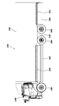
- the following measures are taken. That is, as shown in FIG. 2, on the left and right side surfaces of the truck 100, the space between the loading platform 160 and the first side guard 260 is covered with the first seat 300 and between the loading platform 160 and the second side guard 280. Is covered with the second sheet 320.
- the first sheet 300 and the second sheet 320 have a rectangular shape with long sides extending in the front-rear direction of the vehicle body, and can be, for example, flexible sheets such as fabric.
- One end in the vertical direction of the first seat 300 and the second seat 320 is connected to one of the loading platform 160 and the first side guard 260 or the second side guard 280 via, for example, a fastener including a bolt and a nut. Is fixed. Further, the other ends of the first sheet 300 and the second sheet 320 in the up-down direction are touched to the other of the loading platform 160 and the first side guard 260 or the second side guard 280 via an attaching / detaching tool described later. It is fixed in a removable manner.
- first sheet 300 and the second sheet 320 are fixed to the first side guard 260 and the second side guard 280, respectively.
- the first sheet 300 and the second sheet 320 hang down due to their own weight, for example, the operator holds the first sheet 300 and the second sheet 320. Even if not, the work space can be secured.
- seat 320 may be fixed to the loading platform 160, respectively.
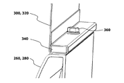
- one end portion of the first sheet 300 and the second sheet 320 is, for example, a first side through an elongated core member 340 having a rectangular cross section. It is being fixed to the guard 260 and the 2nd side guard 280, respectively. That is, the lower ends of the first sheet 300 and the second sheet 320 are wound around the core material 340. And the lower end part of the 1st sheet
- first sheet 300 and the second sheet 320 are sandwiched between the core member 340 and the first side guard 260 and the second side guard 280, so that the sheet material is Is less likely to occur and air resistance can be reduced.
- first sheet 300 and the second sheet 320 are desirably arranged on the same surface as the outer surface of the loading platform 160 and the outer surface of the first side guard 260 or the second side guard 280.
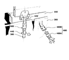
- FIG. 4 shows a first embodiment of the detachable tool.
- a plurality of lower end portions of a belt-like belt 380 extending in the vertical direction are fixed to the upper end portion of the first sheet 300 at predetermined intervals by sewing or the like.
- a male connector 400A of a plastic buckle 400 that can be attached and detached with one touch is attached to the upper end of the belt 380 so that the length can be adjusted.
- a plurality of upper end portions of a belt-like belt 420 extending in the vertical direction are fixed to the lower end portion of the loading platform 160 at positions corresponding to the male connectors 400A of the plastic buckle 400 by fasteners (not shown) including bolts. ing.
- a female connector 400B of a plastic buckle 400 is attached to the lower end portion of the belt 420. Further, the first sheet 300 is formed with a belt-like holding portion 440 through which the intermediate portion of the belt 380 is inserted so as to hold the intermediate portion of the belt 380 having the lower end portion fixed thereto.
- the male connector 400A and the female connector 400B may be attached to the belts 420 and 380, respectively.
- the male connector 400A of the belt 380 fixed to the first sheet 300 is coupled to the female connector 400B of the belt 420 fixed to the loading platform 160, and the free end of the belt 380 is pulled to thereby pull the first sheet 300.
- the upper end portion of the first seat 300 can be removed from the loading platform 160 by releasing the coupling between the male connector 400A of the belt 380 and the female connector 400B of the belt 420.
- the upper end portion of the first sheet 300 is detachably fixed by the plastic buckle 400. And if the upper end part of the 1st sheet
- seat 300 is removed from the loading platform 160, since it hangs down with the dead weight, the fuel tank etc. which are located in the inside can face. For this reason, the fuel consumption of the truck 100 can be improved while considering the maintenance work.
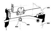
- FIG. 5 shows a second embodiment of the detachable tool.
- a plurality of annular eyelets 460 are fixed to the upper end portion of the first sheet 300 at a predetermined interval.
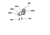
- a plurality of hangers 480 that are detachably fitted to the eyelet 460 are fixed to the lower end portion of the loading platform 160 at positions corresponding to the eyelet 460.
- the hanger 480 includes a plate-like first member 480 ⁇ / b> A serving as an attachment portion to the lower surface of the loading platform 160, and an end portion located on the outer side of the vehicle width of the first member 480 ⁇ / b> A in the vertical direction.
- an elongated oval second member 480B The hanger 480 is fastened and fixed to the lower surface of the loading platform 160 by a bolt 500 which is an example of a fastener through two bolt insertion holes 480C formed in the first member 480A.
- the upper end portion of the first sheet 300 can be fixed to the loading platform 160 by fitting the eyelet 460 of the first sheet 300 to the hanger 480. Further, when the fitting between the eyelet 460 and the hanger 480 of the first sheet 300 is released, the upper end portion of the first sheet 300 can be removed from the loading platform 160. In short, the upper end portion of the first sheet 300 is detachably fixed by the eyelet 460 and the hanger 480. For this reason, the fuel consumption of the truck 100 can be improved while considering the maintenance work. Since other operations and effects are the same as those of the first embodiment, the description thereof is omitted to avoid redundant description. If necessary, refer to the description of the first embodiment (the same applies hereinafter).
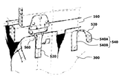
- FIG. 7 shows a third embodiment of the detachable tool.
- a plurality of lower end portions of a belt-like belt 520 extending in the vertical direction are fixed to the upper end portion of the first sheet 300 at predetermined intervals by sewing or the like.
- a hook 540A of a hook-and-loop fastener 540 is affixed to the surface located at the upper end of the belt 520, that is, the surface facing the vehicle width outward. Further, a loop 540B of a hook-and-loop fastener 540 is attached to a portion of the surface of the belt 520 excluding the upper end portion.
- a plurality of square rings 560 that are rotatably coupled to the mounting plate are fixed to the lower end portion of the loading platform 160 at positions corresponding to the belt 520.
- the mounting plate is fastened and fixed to the outer surface of the cargo bed 160 by a fastener (not shown) including bolts, for example.
- the loop 540B may be attached to the upper end portion of the belt 520, and the hook 540A may be attached to a portion other than the upper end portion.
- the first sheet 300 has the leading end of the belt 520 penetrating through the square ring 560 from the inside of the vehicle width, and the hook 540A attached to the leading end is coupled to the loop 540B.
- the upper end portion of 300 can be fixed to the loading platform 160.
- seat 300 can be removed from the loading platform 160 by canceling
- the upper end portion of the first sheet 300 is detachably fixed by the hook-and-loop fastener 540. For this reason, the fuel consumption of the truck 100 can be improved while considering the maintenance work.
- the work space can be secured by removing the upper end of the first seat 300 or the second seat 320 from the loading platform 160.
- the maintenance workability can be further improved by making the following improvements.
- the first sheet 300 will be described, but the same applies to the second sheet 320.
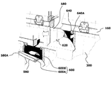
- At least one flap 580 that can be opened and closed is formed on the first sheet 300.
- the flap 580 is formed at a position where, for example, the fuel refill port of the fuel tank can be faced when the flap 580 is opened.
- the flap 580 is formed in a shape in which an upper part in the vertical direction opens and closes. For example, even if the operator does not hold the flap 520, it hangs down by its own weight, and a work space can be secured. Further, at least a part of the outer edge of the flap 580 projects outward from the opening / closing portion.
- hook 600A and the loop 600B of the hook-and-loop fastener 600 are affixed to the inner surface of the portion projecting outward and the outer surface of the first sheet 300 facing the inner surface.
- attachment position of hook 600A and loop 600B of hook-and-loop fastener 600 may be reversed.
- An insertion hole 580A through which the screw 620 is inserted is formed at a corner portion located at the tip (free end) of the flap 580.
- a metal plate 640 is attached to a position corresponding to the insertion hole 580A, thereby forming a female screw 640A into which the screw 620 is screwed.
- the flap 580 can be easily opened and closed by connecting or releasing the hook 600A and the loop 600B of the hook-and-loop fastener 600.
- the flap 580 is fixed by the hook-and-loop fastener 600.
- a work space can be secured without removing the upper end of the first seat 300 from the loading platform 160, so that workability such as fuel replenishment for frequent maintenance work can be improved.
- the flap 580 is fixed to the first sheet 300 by the hook-and-loop fastener 600, there is a possibility that the fixing is released by, for example, traveling wind.
- the corner portion positioned at the tip of the flap 580 is fixed by the screw 620, the flap 580 can be prevented from opening due to traveling wind or the like.
- the flap 580 can be opened and closed by a wire fastener 660 as shown in FIG. 9 instead of the hook-and-loop fastener 600.
- a wire fastener 660 as shown in FIG. 9 instead of the hook-and-loop fastener 600.
- the slider 660A of the wire fastener 660 is fluttered by traveling wind or the like, a strip-shaped storage for storing the slider 660A at one end of the flap 580, that is, the end where the slider 660A is located when the wire fastener 660 is closed.
- a portion 680 may be formed.
- the storage portion 680 may be openable and closable at one end by a hook-and-loop fastener.
- the flap 580 can be easily opened and closed by sliding the slider 660A of the wire fastener 660. Moreover, since the slider 660A does not move easily due to traveling wind or the like in the wire fastener 660, it is not necessary to further fix the slider 660A, and the labor required for opening and closing it can be reduced. Since other operations and effects are the same as those of the hook-and-loop fastener 600 shown in FIG. 8, the description thereof is omitted to eliminate redundant description. If necessary, refer to the previous actions and effects.
Landscapes
- Engineering & Computer Science (AREA)
- Mechanical Engineering (AREA)
- Chemical & Material Sciences (AREA)
- Combustion & Propulsion (AREA)
- Transportation (AREA)
- Body Structure For Vehicles (AREA)
- Packaging Of Machine Parts And Wound Products (AREA)
Abstract
Description
図1は、サイドガードを有するトラックの一例を示す。
即ち、図2に示すように、トラック100の左右側面において、荷台160と第1のサイドガード260との間を第1のシート300で覆うと共に、荷台160と第2のサイドガード280との間を第2のシート320で覆う。第1のシート300及び第2のシート320は、車体の前後方向に長辺が延びる矩形形状をなし、例えば、ファブリックなどの柔軟性を有するシートとすることができる。
第1のシート300の上端部には、所定間隔を隔てた状態で、上下方向に延びる帯状のベルト380の下端部が、縫い付けなどによって複数固定されている。ベルト380の上端部には、ワンタッチで着脱可能なプラスチックバックル400の雄コネクタ400Aが長さ調整可能に取り付けられている。一方、荷台160の下端部には、プラスチックバックル400の雄コネクタ400Aに対応する位置に、上下方向に延びる帯状のベルト420の上端部が、ボルトを含む締結具(図示せず)によって複数固定されている。ベルト420の下端部には、プラスチックバックル400の雌コネクタ400Bが取り付けられている。また、第1のシート300には、ここに下端部が固定されたベルト380の中間部を保持すべく、ベルト380の中間部が挿通される帯状の保持部440が形成されている。なお、雄コネクタ400A及び雌コネクタ400Bは、ベルト420及び380に夫々取り付けられていてもよい。
第1のシート300の上端部には、所定間隔を隔てた状態で、円環形状のアイレット460が複数固定されている。一方、荷台160の下端部には、アイレット460に対応する位置に、アイレット460と着脱可能に嵌合するハンガー480が複数固定されている。ハンガー480は、図6に示すように、荷台160の下面への取付部となる板状の第1の部材480Aと、第1の部材480Aの車幅外方に位置する端部から上下方向に延びる長円形状の第2の部材480Bと、を有する。そして、ハンガー480は、第1の部材480Aに形成された2つのボルト挿通孔480Cを介して、締結具の一例として挙げられるボルト500によって荷台160の下面に締結固定されている。
第1のシート300の上端部には、所定間隔を隔てた状態で、上下方向に延びる帯状のベルト520の下端部が、縫い付けなどによって複数固定されている。ベルト520の上端部に位置する表面、即ち、車幅外方を向く面には、面ファスナー540のフック540Aが貼り付けられている。また、ベルト520の表面のうち上端部を除く部分には、面ファスナー540のループ540Bが貼り付けられている。一方、荷台160の下端部には、ベルト520に対応する位置に、例えば、取付プレートに回転自由に結合された四角リング560が複数固定されている。この取付プレートは、例えば、ボルトを含む締結具(図示せず)により荷台160の外側面に締結固定されている。なお、ベルト520の上端部にループ540Bが貼り付けられ、上端部を除く部分にフック540Aが貼り付けられていてもよい。
160 荷台
260 第1のサイドガード(サイドガード)
280 第2のサイドガード(サイドガード)
300 第1のシート(シート)
320 第2のシート(シート)
340 芯材
400 プラスチックバックル
460 アイレット
480 ハンガー
540 面ファスナー
580 フラップ
600 面ファスナー
620 ねじ
660 線ファスナー
660A スライダー
680 収納部
Claims (12)
- 車体の左右側面において荷台の下面と隔てて板状のサイドガードが取り付けられたトラックのサイドスカートであって、
前記車体の前後方向に延びる矩形形状をなし、前記荷台及び前記サイドガードの一方に上下方向の一端部が固定され、前記荷台及び前記サイドガードの他方に上下方向の他端部が着脱可能に固定された、柔軟性を有するシートを含む、
ことを特徴とするトラックのサイドスカート。 - 前記シートには、開閉可能なフラップが少なくとも1つ形成されている、
ことを特徴とする請求項1に記載のトラックのサイドスカート。 - 前記フラップは、面ファスナーによって固定されている、
ことを特徴とする請求項2に記載のトラックのサイドスカート。 - 前記フラップの先端に位置する角部は、ねじによって固定されている、
ことを特徴とする請求項3に記載のトラックのサイドスカート。 - 前記フラップは、線ファスナーによって固定されている、
ことを特徴とする請求項2に記載のトラックのサイドスカート。 - 前記フラップの外縁の一端部に、前記線ファスナーのスライダーを収納する収納部が形成されている、
ことを特徴とする請求項5に記載のトラックのサイドスカート。 - 前記フラップは、上下方向の上部が開閉する、
ことを特徴とする請求項2~請求項6のいずれか1つに記載のトラックのサイドスカート。 - 前記シートの他端部は、プラスチックバックルによって着脱可能に固定されている、
ことを特徴とする請求項1~請求項7のいずれか1つに記載のトラックのサイドスカート。 - 前記シートの他端部は、アイレット及びハンガーによって着脱可能に固定されている、
ことを特徴とする請求項1~請求項7のいずれか1つに記載のトラックのサイドスカート。 - 前記シートの他端部は、面ファスナーによって着脱可能に固定されている、
ことを特徴とする請求項1~請求項7のいずれか1つに記載のトラックのサイドスカート。 - 前記シートの一端部は、芯材を介して前記荷台又は前記サイドガードに固定されている、
ことを特徴とする請求項1~請求項10のいずれか1つに記載のトラックのサイドスカート。 - 前記シートの一端部は、前記サイドガードに固定されている、
ことを特徴とする請求項1~請求項11のいずれか1つに記載のトラックのサイドスカート。
Priority Applications (4)
| Application Number | Priority Date | Filing Date | Title |
|---|---|---|---|
| JP2017557533A JP6625664B2 (ja) | 2015-12-21 | 2015-12-21 | トラックのサイドスカート |
| EP15911269.7A EP3395657B1 (en) | 2015-12-21 | 2015-12-21 | Truck side - skirt |
| US16/063,177 US10875586B2 (en) | 2015-12-21 | 2015-12-21 | Truck side-skirt |
| PCT/JP2015/085670 WO2017109831A1 (ja) | 2015-12-21 | 2015-12-21 | トラックのサイドスカート |
Applications Claiming Priority (1)
| Application Number | Priority Date | Filing Date | Title |
|---|---|---|---|
| PCT/JP2015/085670 WO2017109831A1 (ja) | 2015-12-21 | 2015-12-21 | トラックのサイドスカート |
Publications (1)
| Publication Number | Publication Date |
|---|---|
| WO2017109831A1 true WO2017109831A1 (ja) | 2017-06-29 |
Family
ID=59090955
Family Applications (1)
| Application Number | Title | Priority Date | Filing Date |
|---|---|---|---|
| PCT/JP2015/085670 Ceased WO2017109831A1 (ja) | 2015-12-21 | 2015-12-21 | トラックのサイドスカート |
Country Status (4)
| Country | Link |
|---|---|
| US (1) | US10875586B2 (ja) |
| EP (1) | EP3395657B1 (ja) |
| JP (1) | JP6625664B2 (ja) |
| WO (1) | WO2017109831A1 (ja) |
Cited By (1)
| Publication number | Priority date | Publication date | Assignee | Title |
|---|---|---|---|---|
| CN107901863A (zh) * | 2017-11-15 | 2018-04-13 | 安徽江淮汽车集团股份有限公司 | 一种手动伸缩自锁型卡车侧防护栏装置 |
Families Citing this family (4)
| Publication number | Priority date | Publication date | Assignee | Title |
|---|---|---|---|---|
| WO2017109831A1 (ja) * | 2015-12-21 | 2017-06-29 | ボルボ トラック コーポレーション | トラックのサイドスカート |
| US10857961B2 (en) | 2018-05-23 | 2020-12-08 | Hydro Extrusion USA, LLC | Mounting system for truck underride protection |
| US11713013B2 (en) | 2020-07-09 | 2023-08-01 | Fontaine Commercial Trailer, Inc. | Side underride guard assembly for a trailer |
| EP4124547A1 (de) * | 2021-07-26 | 2023-02-01 | Schmitz Cargobull AG | Nutzfahrzeug mit seitlicher anfahrschutzvorrichtung |
Citations (5)
| Publication number | Priority date | Publication date | Assignee | Title |
|---|---|---|---|---|
| JPH0224787U (ja) * | 1988-08-04 | 1990-02-19 | ||
| JP2005161960A (ja) | 2003-12-02 | 2005-06-23 | Hino Motors Ltd | 車両のサイドガード |
| JP2013119302A (ja) * | 2011-12-07 | 2013-06-17 | Daimler Ag | トラックのサイドスカート装置 |
| JP2014031066A (ja) * | 2012-08-02 | 2014-02-20 | Isuzu Motors Ltd | 車体の下部構造 |
| US20140159419A1 (en) * | 2012-12-11 | 2014-06-12 | Leonard W. Baker | Flexible panel member for a trailer side skirt system |
Family Cites Families (22)
| Publication number | Priority date | Publication date | Assignee | Title |
|---|---|---|---|---|
| JPS5544009A (en) * | 1978-09-19 | 1980-03-28 | Nissan Diesel Motor Co Ltd | Noise preventive apparatus also used for safety guard for car having freight bed |
| US4746160A (en) * | 1986-06-30 | 1988-05-24 | Wiesemeyer Robert L | Streamlined truck with semitrailer |
| JPH0224787A (ja) | 1988-07-14 | 1990-01-26 | Ricoh Co Ltd | 最適2値化方法 |
| US5280990A (en) * | 1991-10-08 | 1994-01-25 | Rinard Gordon L | Vehicle drag reduction system |
| US7093889B2 (en) * | 2004-10-04 | 2006-08-22 | Freight Wing Inc. | Device for reducing vehicle aerodynamic resistance |
| US7686385B2 (en) * | 2006-02-02 | 2010-03-30 | U-Haul International, Inc. | Flexible truck skirt with floating mount |
| US7578546B2 (en) * | 2007-03-20 | 2009-08-25 | International Truck Intellectual Property Company, Llc | Removable chassis skirt |
| US8408570B2 (en) * | 2008-02-21 | 2013-04-02 | Aerofficient Llc | Vehicle side fairing system |
| MX345182B (es) * | 2009-04-16 | 2017-01-19 | Wabash National Lp | Faldón lateral y sistema de cable lateral antiempotramiento para un remolque. |
| US20110095563A1 (en) * | 2009-10-27 | 2011-04-28 | Stanley Andersen | Vehicle underbody airflow modulator |
| US8210599B2 (en) * | 2010-05-24 | 2012-07-03 | Joshua Butler | Aerodynamic and protective vehicle panel assembly and method of constructing same |
| US8366180B2 (en) * | 2010-10-13 | 2013-02-05 | Hyundai Translead | Vehicle air deflection system |
| DE202011004055U1 (de) | 2011-03-16 | 2013-01-02 | Dieter Ramsauer | Kabelfang |
| US8857893B2 (en) * | 2012-05-24 | 2014-10-14 | Aerofficient, Llc | Intermodal chassis side fairing system |
| US10189517B2 (en) * | 2014-03-21 | 2019-01-29 | Magna Exteriors, Inc. | Deployable aerodynamic side panel system |
| US9463759B1 (en) * | 2014-10-29 | 2016-10-11 | Aaron J. Kiefer | Underride guards |
| WO2017109831A1 (ja) * | 2015-12-21 | 2017-06-29 | ボルボ トラック コーポレーション | トラックのサイドスカート |
| US10435083B2 (en) * | 2016-08-10 | 2019-10-08 | Ekostinger, Inc. | Aerodynamic recapture method and apparatus |
| WO2018097815A1 (en) * | 2016-11-22 | 2018-05-31 | Compagnie Generale Des Etablissements Michelin | Aerodynamic trailer system with dual stiffness skirt |
| WO2019014503A1 (en) * | 2017-07-12 | 2019-01-17 | FlowBelow Aero, Inc. | AERODYNAMIC TOOLBOX SET |
| US10882572B2 (en) * | 2018-03-07 | 2021-01-05 | Windyne Fairing Co. Ltd. | Trailer underbody fairing system |
| US10946907B2 (en) * | 2018-06-14 | 2021-03-16 | Tank Trailer Technologies LLC | Aerodynamic curtain assembly for a tank trailer |
-
2015
- 2015-12-21 WO PCT/JP2015/085670 patent/WO2017109831A1/ja not_active Ceased
- 2015-12-21 US US16/063,177 patent/US10875586B2/en not_active Expired - Fee Related
- 2015-12-21 JP JP2017557533A patent/JP6625664B2/ja not_active Expired - Fee Related
- 2015-12-21 EP EP15911269.7A patent/EP3395657B1/en active Active
Patent Citations (5)
| Publication number | Priority date | Publication date | Assignee | Title |
|---|---|---|---|---|
| JPH0224787U (ja) * | 1988-08-04 | 1990-02-19 | ||
| JP2005161960A (ja) | 2003-12-02 | 2005-06-23 | Hino Motors Ltd | 車両のサイドガード |
| JP2013119302A (ja) * | 2011-12-07 | 2013-06-17 | Daimler Ag | トラックのサイドスカート装置 |
| JP2014031066A (ja) * | 2012-08-02 | 2014-02-20 | Isuzu Motors Ltd | 車体の下部構造 |
| US20140159419A1 (en) * | 2012-12-11 | 2014-06-12 | Leonard W. Baker | Flexible panel member for a trailer side skirt system |
Cited By (1)
| Publication number | Priority date | Publication date | Assignee | Title |
|---|---|---|---|---|
| CN107901863A (zh) * | 2017-11-15 | 2018-04-13 | 安徽江淮汽车集团股份有限公司 | 一种手动伸缩自锁型卡车侧防护栏装置 |
Also Published As
| Publication number | Publication date |
|---|---|
| JPWO2017109831A1 (ja) | 2018-10-04 |
| US10875586B2 (en) | 2020-12-29 |
| EP3395657A4 (en) | 2019-05-15 |
| EP3395657A1 (en) | 2018-10-31 |
| EP3395657B1 (en) | 2020-04-01 |
| US20190308675A1 (en) | 2019-10-10 |
| JP6625664B2 (ja) | 2019-12-25 |
Similar Documents
| Publication | Publication Date | Title |
|---|---|---|
| JP6625664B2 (ja) | トラックのサイドスカート | |
| US20110180345A1 (en) | Cowling structure for saddle-ride type vehicle | |
| ATE526194T1 (de) | Kühllufteinlassstruktur einer batterie | |
| US8864157B2 (en) | Rear portion structure for a saddle type vehicle | |
| JP5984052B2 (ja) | 電池パックの位置決めピンブラケット | |
| CN104870298B (zh) | 车身后部结构 | |
| US20180327034A1 (en) | Vehicular mud guard structure | |
| JP2015044534A (ja) | 鞍乗り型車両のシート支持構造 | |
| JP2009241900A5 (ja) | ||
| TW201637920A (zh) | 跨坐型車輛之收納部構造 | |
| JP6029448B2 (ja) | 鞍乗型車両 | |
| JP5961086B2 (ja) | 鞍乗り型車両の前部構造 | |
| CN101112904A (zh) | 备用轮胎安装结构 | |
| JP2013189171A (ja) | 鞍乗型車両の吸気構造 | |
| JP4078341B2 (ja) | 自動二輪車における車体カバー構造 | |
| EP3431377B1 (en) | A straddle-type vehicle comprising a front structure | |
| US9694667B2 (en) | Working vehicle | |
| AU2016204229A1 (en) | Part attachment structure of straddle type vehicle | |
| JP2016182928A (ja) | 不整地走行車両 | |
| US20150217827A1 (en) | Straddle-Type Vehicle | |
| JP4766971B2 (ja) | 乗物の装備品収納構造 | |
| US9446809B2 (en) | Frame covering device with air vents | |
| CN204161538U (zh) | 工具绑带机构 | |
| JP2013189172A (ja) | 鞍乗型車両の吸気構造 | |
| US20200164931A1 (en) | Vehicle |
Legal Events
| Date | Code | Title | Description |
|---|---|---|---|
| 121 | Ep: the epo has been informed by wipo that ep was designated in this application |
Ref document number: 15911269 Country of ref document: EP Kind code of ref document: A1 |
|
| ENP | Entry into the national phase |
Ref document number: 2017557533 Country of ref document: JP Kind code of ref document: A |
|
| NENP | Non-entry into the national phase |
Ref country code: DE |
|
| WWE | Wipo information: entry into national phase |
Ref document number: 2015911269 Country of ref document: EP |
|
| ENP | Entry into the national phase |
Ref document number: 2015911269 Country of ref document: EP Effective date: 20180723 |