WO2017109965A1 - 3次元積層造形装置、3次元積層造形装置の制御方法および3次元積層造形装置の制御プログラム - Google Patents
3次元積層造形装置、3次元積層造形装置の制御方法および3次元積層造形装置の制御プログラム Download PDFInfo
- Publication number
- WO2017109965A1 WO2017109965A1 PCT/JP2015/086305 JP2015086305W WO2017109965A1 WO 2017109965 A1 WO2017109965 A1 WO 2017109965A1 JP 2015086305 W JP2015086305 W JP 2015086305W WO 2017109965 A1 WO2017109965 A1 WO 2017109965A1
- Authority
- WO
- WIPO (PCT)
- Prior art keywords
- recoater
- material spraying
- temperature
- additive manufacturing
- cooling
- Prior art date
- Legal status (The legal status is an assumption and is not a legal conclusion. Google has not performed a legal analysis and makes no representation as to the accuracy of the status listed.)
- Ceased
Links
Images



Classifications
-
- B—PERFORMING OPERATIONS; TRANSPORTING
- B33—ADDITIVE MANUFACTURING TECHNOLOGY
- B33Y—ADDITIVE MANUFACTURING, i.e. MANUFACTURING OF THREE-DIMENSIONAL [3D] OBJECTS BY ADDITIVE DEPOSITION, ADDITIVE AGGLOMERATION OR ADDITIVE LAYERING, e.g. BY 3D PRINTING, STEREOLITHOGRAPHY OR SELECTIVE LASER SINTERING
- B33Y30/00—Apparatus for additive manufacturing; Details thereof or accessories therefor
-
- B—PERFORMING OPERATIONS; TRANSPORTING
- B22—CASTING; POWDER METALLURGY
- B22F—WORKING METALLIC POWDER; MANUFACTURE OF ARTICLES FROM METALLIC POWDER; MAKING METALLIC POWDER; APPARATUS OR DEVICES SPECIALLY ADAPTED FOR METALLIC POWDER
- B22F3/00—Manufacture of workpieces or articles from metallic powder characterised by the manner of compacting or sintering; Apparatus specially adapted therefor ; Presses and furnaces
- B22F3/10—Sintering only
- B22F3/105—Sintering only by using electric current other than for infrared radiant energy, laser radiation or plasma ; by ultrasonic bonding
-
- B—PERFORMING OPERATIONS; TRANSPORTING
- B22—CASTING; POWDER METALLURGY
- B22F—WORKING METALLIC POWDER; MANUFACTURE OF ARTICLES FROM METALLIC POWDER; MAKING METALLIC POWDER; APPARATUS OR DEVICES SPECIALLY ADAPTED FOR METALLIC POWDER
- B22F12/00—Apparatus or devices specially adapted for additive manufacturing; Auxiliary means for additive manufacturing; Combinations of additive manufacturing apparatus or devices with other processing apparatus or devices
- B22F12/20—Cooling means
-
- B—PERFORMING OPERATIONS; TRANSPORTING
- B22—CASTING; POWDER METALLURGY
- B22F—WORKING METALLIC POWDER; MANUFACTURE OF ARTICLES FROM METALLIC POWDER; MAKING METALLIC POWDER; APPARATUS OR DEVICES SPECIALLY ADAPTED FOR METALLIC POWDER
- B22F12/00—Apparatus or devices specially adapted for additive manufacturing; Auxiliary means for additive manufacturing; Combinations of additive manufacturing apparatus or devices with other processing apparatus or devices
- B22F12/60—Planarisation devices; Compression devices
-
- B—PERFORMING OPERATIONS; TRANSPORTING
- B22—CASTING; POWDER METALLURGY
- B22F—WORKING METALLIC POWDER; MANUFACTURE OF ARTICLES FROM METALLIC POWDER; MAKING METALLIC POWDER; APPARATUS OR DEVICES SPECIALLY ADAPTED FOR METALLIC POWDER
- B22F3/00—Manufacture of workpieces or articles from metallic powder characterised by the manner of compacting or sintering; Apparatus specially adapted therefor ; Presses and furnaces
- B22F3/12—Both compacting and sintering
- B22F3/16—Both compacting and sintering in successive or repeated steps
-
- B—PERFORMING OPERATIONS; TRANSPORTING
- B23—MACHINE TOOLS; METAL-WORKING NOT OTHERWISE PROVIDED FOR
- B23K—SOLDERING OR UNSOLDERING; WELDING; CLADDING OR PLATING BY SOLDERING OR WELDING; CUTTING BY APPLYING HEAT LOCALLY, e.g. FLAME CUTTING; WORKING BY LASER BEAM
- B23K15/00—Electron-beam welding or cutting
- B23K15/0026—Auxiliary equipment
-
- B—PERFORMING OPERATIONS; TRANSPORTING
- B23—MACHINE TOOLS; METAL-WORKING NOT OTHERWISE PROVIDED FOR
- B23K—SOLDERING OR UNSOLDERING; WELDING; CLADDING OR PLATING BY SOLDERING OR WELDING; CUTTING BY APPLYING HEAT LOCALLY, e.g. FLAME CUTTING; WORKING BY LASER BEAM
- B23K15/00—Electron-beam welding or cutting
- B23K15/0046—Welding
- B23K15/0086—Welding welding for purposes other than joining, e.g. build-up welding
-
- B—PERFORMING OPERATIONS; TRANSPORTING
- B29—WORKING OF PLASTICS; WORKING OF SUBSTANCES IN A PLASTIC STATE IN GENERAL
- B29C—SHAPING OR JOINING OF PLASTICS; SHAPING OF MATERIAL IN A PLASTIC STATE, NOT OTHERWISE PROVIDED FOR; AFTER-TREATMENT OF THE SHAPED PRODUCTS, e.g. REPAIRING
- B29C64/00—Additive manufacturing, i.e. manufacturing of three-dimensional [3D] objects by additive deposition, additive agglomeration or additive layering, e.g. by 3D printing, stereolithography or selective laser sintering
- B29C64/20—Apparatus for additive manufacturing; Details thereof or accessories therefor
- B29C64/205—Means for applying layers
-
- B—PERFORMING OPERATIONS; TRANSPORTING
- B29—WORKING OF PLASTICS; WORKING OF SUBSTANCES IN A PLASTIC STATE IN GENERAL
- B29C—SHAPING OR JOINING OF PLASTICS; SHAPING OF MATERIAL IN A PLASTIC STATE, NOT OTHERWISE PROVIDED FOR; AFTER-TREATMENT OF THE SHAPED PRODUCTS, e.g. REPAIRING
- B29C64/00—Additive manufacturing, i.e. manufacturing of three-dimensional [3D] objects by additive deposition, additive agglomeration or additive layering, e.g. by 3D printing, stereolithography or selective laser sintering
- B29C64/30—Auxiliary operations or equipment
- B29C64/386—Data acquisition or data processing for additive manufacturing
- B29C64/393—Data acquisition or data processing for additive manufacturing for controlling or regulating additive manufacturing processes
-
- B—PERFORMING OPERATIONS; TRANSPORTING
- B33—ADDITIVE MANUFACTURING TECHNOLOGY
- B33Y—ADDITIVE MANUFACTURING, i.e. MANUFACTURING OF THREE-DIMENSIONAL [3D] OBJECTS BY ADDITIVE DEPOSITION, ADDITIVE AGGLOMERATION OR ADDITIVE LAYERING, e.g. BY 3D PRINTING, STEREOLITHOGRAPHY OR SELECTIVE LASER SINTERING
- B33Y10/00—Processes of additive manufacturing
-
- B—PERFORMING OPERATIONS; TRANSPORTING
- B33—ADDITIVE MANUFACTURING TECHNOLOGY
- B33Y—ADDITIVE MANUFACTURING, i.e. MANUFACTURING OF THREE-DIMENSIONAL [3D] OBJECTS BY ADDITIVE DEPOSITION, ADDITIVE AGGLOMERATION OR ADDITIVE LAYERING, e.g. BY 3D PRINTING, STEREOLITHOGRAPHY OR SELECTIVE LASER SINTERING
- B33Y50/00—Data acquisition or data processing for additive manufacturing
-
- B—PERFORMING OPERATIONS; TRANSPORTING
- B33—ADDITIVE MANUFACTURING TECHNOLOGY
- B33Y—ADDITIVE MANUFACTURING, i.e. MANUFACTURING OF THREE-DIMENSIONAL [3D] OBJECTS BY ADDITIVE DEPOSITION, ADDITIVE AGGLOMERATION OR ADDITIVE LAYERING, e.g. BY 3D PRINTING, STEREOLITHOGRAPHY OR SELECTIVE LASER SINTERING
- B33Y50/00—Data acquisition or data processing for additive manufacturing
- B33Y50/02—Data acquisition or data processing for additive manufacturing for controlling or regulating additive manufacturing processes
-
- B—PERFORMING OPERATIONS; TRANSPORTING
- B22—CASTING; POWDER METALLURGY
- B22F—WORKING METALLIC POWDER; MANUFACTURE OF ARTICLES FROM METALLIC POWDER; MAKING METALLIC POWDER; APPARATUS OR DEVICES SPECIALLY ADAPTED FOR METALLIC POWDER
- B22F10/00—Additive manufacturing of workpieces or articles from metallic powder
- B22F10/20—Direct sintering or melting
- B22F10/28—Powder bed fusion, e.g. selective laser melting [SLM] or electron beam melting [EBM]
-
- B—PERFORMING OPERATIONS; TRANSPORTING
- B22—CASTING; POWDER METALLURGY
- B22F—WORKING METALLIC POWDER; MANUFACTURE OF ARTICLES FROM METALLIC POWDER; MAKING METALLIC POWDER; APPARATUS OR DEVICES SPECIALLY ADAPTED FOR METALLIC POWDER
- B22F10/00—Additive manufacturing of workpieces or articles from metallic powder
- B22F10/30—Process control
- B22F10/36—Process control of energy beam parameters
- B22F10/362—Process control of energy beam parameters for preheating
-
- B—PERFORMING OPERATIONS; TRANSPORTING
- B22—CASTING; POWDER METALLURGY
- B22F—WORKING METALLIC POWDER; MANUFACTURE OF ARTICLES FROM METALLIC POWDER; MAKING METALLIC POWDER; APPARATUS OR DEVICES SPECIALLY ADAPTED FOR METALLIC POWDER
- B22F2203/00—Controlling
- B22F2203/03—Controlling for feed-back
-
- B—PERFORMING OPERATIONS; TRANSPORTING
- B22—CASTING; POWDER METALLURGY
- B22F—WORKING METALLIC POWDER; MANUFACTURE OF ARTICLES FROM METALLIC POWDER; MAKING METALLIC POWDER; APPARATUS OR DEVICES SPECIALLY ADAPTED FOR METALLIC POWDER
- B22F2203/00—Controlling
- B22F2203/11—Controlling temperature, temperature profile
-
- Y—GENERAL TAGGING OF NEW TECHNOLOGICAL DEVELOPMENTS; GENERAL TAGGING OF CROSS-SECTIONAL TECHNOLOGIES SPANNING OVER SEVERAL SECTIONS OF THE IPC; TECHNICAL SUBJECTS COVERED BY FORMER USPC CROSS-REFERENCE ART COLLECTIONS [XRACs] AND DIGESTS
- Y02—TECHNOLOGIES OR APPLICATIONS FOR MITIGATION OR ADAPTATION AGAINST CLIMATE CHANGE
- Y02P—CLIMATE CHANGE MITIGATION TECHNOLOGIES IN THE PRODUCTION OR PROCESSING OF GOODS
- Y02P10/00—Technologies related to metal processing
- Y02P10/25—Process efficiency
Definitions
- the present invention relates to a control method for a three-dimensional additive manufacturing apparatus, a control method for the three-dimensional additive manufacturing apparatus, and a control program for the three-dimensional additive manufacturing apparatus.
- Patent Document 1 discloses a technique for cooling a recoater roller to cool a powder material (paragraph [0054], etc.).
- An object of the present invention is to provide a technique for solving the above-described problems.
- a three-dimensional additive manufacturing apparatus At least one material spraying means for spraying the material of the three-dimensional layered object; Temperature measuring means for measuring the temperature of the material spraying means; At least one cooling means for cooling the material spraying means, provided at a standby position where the material spraying means waits when the material is not sprayed; Control means for controlling the material spraying means; With The control means moves the spraying means to the standby position to bring the material spraying means and the cooling means into contact with each other.
- a method for controlling a three-dimensional additive manufacturing apparatus includes: A material spreading step of spreading the material by the material spreading means; A temperature measuring step for measuring the temperature of the material spraying means; Control step of controlling the movement of the material spraying means so that the material spraying means and the cooling means of the material spraying means provided at the standby position where the material spraying means waits when the material is not sprayed.
- a control program for a three-dimensional additive manufacturing apparatus is: A material spreading step of spreading the material by the material spreading means; A temperature measuring step for measuring the temperature of the material spraying means; The movement of the material spraying means is controlled so that the cooling means for cooling the material spraying means provided at the standby position where the material spraying means waits when the material is not sprayed is brought into contact with the material spraying means. Control steps; Is executed on the computer.
- the recoater driven two-dimensionally can be cooled with a simple structure.
- a three-dimensional additive manufacturing apparatus 100 as a first embodiment of the present invention will be described with reference to FIGS. 1 to 6.
- the 3D additive manufacturing apparatus 100 stacks materials by spraying a material 120 of a three-dimensional additive manufacturing object on a modeling surface and irradiating the dispersed material 120 with an electron beam or the like to melt and solidify the material. This is a device for modeling a three-dimensional layered object.
- FIG. 6A is a diagram illustrating a three-dimensional additive manufacturing apparatus 600 according to a prerequisite technique of the three-dimensional additive manufacturing apparatus according to the present embodiment.
- FIG. 6B is a diagram illustrating a temperature change due to radiant heat of the three-dimensional additive manufacturing apparatus 600 recoater 601 according to the prerequisite technology of the three-dimensional additive manufacturing apparatus according to the embodiment.
- the three-dimensional additive manufacturing apparatus 600 includes a recoater 601.
- the recoater 601 is in close proximity to the modeling surface (layered modeling surface) of the three-dimensional layered object 630 and sprays metal powder or the like that is the material 620 of the three-dimensional layered object 630.
- the three-dimensional additive manufacturing apparatus 600 forms a three-dimensional additive object by irradiating the dispersed material 620 with a beam such as an electron beam to melt and solidify the material 620.
- the recoater 611 is attached to the recoater 601.
- the recoater 601 moves two-dimensionally and spreads the material 620 on the layered modeling surface.
- the recoater position control unit 603 controls the recoater driver 611 by transmitting a control signal to the recoater driver 611.
- the material 620 is preheated and heated by an electron beam or the like, and the surface temperature of the material 620 may be about 1000 ° C. depending on the lamination conditions.
- the recoater 601 receives heat from the gas atmosphere if the modeling chamber is filled with a gas atmosphere, and receives and radiates heat 640 from the preheated or heated material 620 if the modeling chamber is vacuum. . As a result, the temperature of the recoater 601 increases. Since the recoater 601 is made of a metal such as stainless steel or iron, a cooler 670 is attached to the recoater 601 so that the temperature of the recoater 601 does not rise to a temperature higher than the heat resistance temperature (melting temperature) of the recoater 601. It has been. The cooler 670 is provided with a cooling pipe 671 that allows the refrigerant to flow to the cooler 670. The recoater 601 is cooled by a cooler 670.
- the time point when the recoater 601 moves onto the surface of the material 620 is defined as “start”. If cooler 670 is attached to recoater 601, as shown in graph 680, the temperature of recoater 601 can be maintained within the control temperature range (TCmin to TCmax).
- the recoater 601 cannot be sufficiently cooled as shown in the graph 690, and the recoater 601 The temperature reaches the maximum temperature (Tmax).
- Tmax the maximum temperature
- the modeling chamber is vacuum, there is no escape for heat accumulated in the recoater 601, and the temperature of the recoater 601 easily reaches the maximum temperature.
- FIGS. 1 and FIG. 2 are diagrams showing an outline of the configuration of the three-dimensional additive manufacturing apparatus according to the present embodiment, and show a state in which a material is sprayed and a state in which the recoater is cooled, respectively.
- the three-dimensional additive manufacturing apparatus 100 includes a recoater 101, a temperature measuring unit 102, a recoater cooling control unit 103, and a cooling head 104.
- the recoater 101 is a material spraying mechanism that sprays metal powder such as titanium (Ti), which is the material 120 of the three-dimensional layered object 130, onto the modeling surface, and two-dimensionally (XY direction) on the modeling surface. To drive.
- metal powder such as titanium (Ti)
- Ti titanium
- a recoater driver 111 is attached to the recoater 101.
- the recoater position control unit 150 controls the movement of the recoater 101. Specifically, the recoater position control unit 150 transmits a control signal to the recoater driver 111, and the recoater driver 111 that has received the control signal causes the recoater 101 to move in two dimensions based on the received control signal. To drive.
- the temperature measuring unit 102 measures the temperature of the recoater 101.
- the material 120 is maintained at a high temperature by heating with a heater (not shown) or preheating or heating by irradiation with an electron beam.
- a heater not shown
- the recoater 101 is heated by the heat of the gas being filled or the radiant heat of the material 120 heated to a high temperature. Is done.
- the temperature measuring unit 102 transmits an alert signal indicating that the temperature has become equal to or higher than the predetermined temperature to the recoater cooling control unit 103.
- the recoater cooling control unit 103 that has received the alert signal transmits a signal to the recoater position control unit 150 and the elevation control unit 143.
- the recoater position control unit 150 controls the recoater driver 111 to move the recoater 101 to the standby position (home position), that is, the space above the cooling head 104.
- the lift control unit 143 transmits a signal to the lift 142.
- the elevator 142 that has received the signal raises the cooling head 104 to a predetermined position, and brings the cooling head 104 raised to the predetermined position into contact with the recoater 101 that has moved to the standby position. Thereby, since the heat stored in the recoater 101 moves to the cooling head 104, the temperature of the recoater 101 is lowered.
- the cooling head 104 is made of, for example, a metal having a high thermal conductivity such as copper (Cu), silver (Ag), gold (Au), aluminum (Al), zinc (Zn), nickel (Ni), or iron (Fe). Although representative, it is not limited to these, These alloys etc. may be sufficient.
- the cooling head 104 is in contact with the cooling medium 141 (heat sink) when the recoater 101 is not in the standby position, for example, when the recoater 101 is spraying the material 120. In this state, the cooling head 104 is conducted from the recoater 101 and dissipates heat stored in the cooling head 104.
- the recoater 101 stands by at a standby position (home position) while, for example, the material 120 is irradiated with an electron beam or the like. Further, the recoater 101 may be replenished with 120 of the material while the recoater 101 is at the standby position and is in contact with the cooling head 104, or may be performed when the cooling of the recoater 101 is completed. .
- FIG. 3 is a diagram for explaining a temperature change of the recoater 101 of the three-dimensional additive manufacturing apparatus 100 according to the present embodiment.
- the temperature of the recoater 101 that started the spraying of the material 120 gradually increases and eventually reaches the allowable maximum temperature (TCmax).
- TCmax allowable maximum temperature
- the recoater 101 moves to the standby position (home position), contacts the cooling head 104, and dissipates the heat stored in the recoater 101.
- the temperature of the recoater 101 decreases and eventually reaches the cooling temperature (period t0).
- the recoater 101 When the temperature of the recoater 101 decreases to the cooling temperature, the recoater 101 resumes the dispersion of the material 120.
- the temperature of the recoater 101 that has resumed the spraying of the material 120 starts to rise again and reaches the maximum allowable temperature again (period t1).
- the recoater 101 moves again to the standby position, contacts the cooling head 104, and dissipates the heat stored in the recoater 101. Then, the recoater 101 resumes the dispersion of the material 120.
- the three-dimensional additive manufacturing apparatus 100 performs control so that the temperature of the recoater 101 falls within the control temperature range (TCmax to TCmin). By controlling in this way, the temperature of the recoater 101 does not exceed the maximum temperature (Tmax).
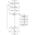
- FIG. 4 is a flowchart illustrating a cooling procedure of the recoater 101 of the three-dimensional additive manufacturing apparatus 100 according to the present embodiment.
- the three-dimensional additive manufacturing apparatus 100 creates a dispersion plan for the material 120 (the position of the recoater 101 on the modeling surface).
- the three-dimensional additive manufacturing apparatus 100 disperses the material 120 by scanning the recoater 101 on the modeling surface in accordance with the created distribution plan.
- the temperature measurement unit 102 measures the temperature of the recoater 101 at predetermined time intervals (fixed time intervals).
- the three-dimensional additive manufacturing apparatus 100 determines whether or not the temperature of the recoater 101 is within the control temperature range. If the temperature of the recoater 101 is within the control temperature range, the three-dimensional additive manufacturing apparatus 100 proceeds to step S409.
- step S407 if the temperature of the recoater 101 is not within the control temperature range, that is, if the temperature of the recoater 101 reaches the allowable maximum temperature or exceeds the allowable maximum temperature, the three-dimensional additive manufacturing apparatus 100 is The process proceeds to step S413.
- step S413 the three-dimensional additive manufacturing apparatus 100 interrupts the spraying of the material 120, stores the position where the recoater 101 interrupts the material spraying, and moves the recoater 101 to the standby position. In other words, when the temperature of the recoater 101 exceeds a predetermined temperature, the recoater 101 is retracted to the standby position in order to prevent damage to the recoater 101 and the like even during material spraying.
- step S415 the three-dimensional additive manufacturing apparatus 100 cools the recoater 101.
- step S417 the three-dimensional additive manufacturing apparatus 100 resumes the dispersion of the material 120 from the position where the material dispersion is interrupted.
- the three-dimensional additive manufacturing apparatus 100 may include a history storage unit that stores a history of material spraying by the recoater 101 when the material spraying is interrupted. And when the recoater 101 restarts material distribution, you may restart material distribution based on this log
- step S409 the three-dimensional additive manufacturing apparatus 100 completes the created spray plan and determines whether or not the material 120 has been sprayed. If the spraying plan is not completed and the spraying of the material 120 is not completed, the three-dimensional additive manufacturing apparatus 100 returns to step S403 and repeats the subsequent steps.
- step S411 moves the recoater 101 to the standby position, and cools the recoater 101.
- FIG. 5 is a flowchart for explaining a recoater cooling procedure by the three-dimensional additive manufacturing apparatus 100 according to the present embodiment.
- step S501 the three-dimensional additive manufacturing apparatus 100 moves the recoater 101 to return to the standby position (home position).
- step S ⁇ b> 503 the three-dimensional additive manufacturing apparatus 100 raises the elevator 142 to bring the recoater 101 and the cooling head 104 into contact with each other.
- step S505 the temperature measurement unit 102 measures the temperature of the recoater 101.
- the three-dimensional additive manufacturing apparatus 100 determines whether the temperature of the recoater 101 has dropped below the cooling temperature. If it is determined that the temperature has not dropped below the cooling temperature, the three-dimensional additive manufacturing apparatus 100 returns to step S505 and repeats the subsequent steps.
- step S509 the three-dimensional additive manufacturing apparatus 100 lowers the elevator 142 so that the recoater 101 and the cooling head 104 are separated.
- the recoater driven two-dimensionally can be cooled with a simple structure. Further, the movement of the recoater is not limited, and the accuracy of position control is improved. Furthermore, since the recoater has no extra equipment, the recoater can be reduced in weight, and the recoater can be moved at high speed. The temperature of the recoater can be maintained within a certain range, and the material can be replenished when the recoater is in the standby position, thereby reducing time loss.
- FIG. 7 is a diagram for explaining the outline of the configuration of the three-dimensional additive manufacturing apparatus 700 according to this embodiment.
- the three-dimensional additive manufacturing apparatus 700 according to the present embodiment is different from the first embodiment in that it has two cooling heads. Since other configurations and operations are the same as those in the first embodiment, the same configurations and operations are denoted by the same reference numerals, and detailed description thereof is omitted.
- the three-dimensional additive manufacturing apparatus 700 further includes a cooling head 704. That is, the three-dimensional additive manufacturing apparatus has two standby positions (home positions) of the recoater 101. As a result of the temperature measurement by the temperature measurement unit 102, when the temperature of the recoater 101 is equal to or higher than a predetermined temperature (allowable maximum temperature), an alert signal indicating that the temperature is higher than the predetermined temperature is displayed on the recoater cooling control unit. 103.
- the recoater cooling control unit 103 that has received the alert signal, based on the position of the recoater 101, has a shorter distance from the current position of the recoater 101 out of the two standby positions, that is, the movement time of the recoater 101 is shorter. The recoater 101 is moved to the standby position.
- the recoater cooling control unit 103 controls the recoater position control unit 150 and the elevation control unit 143 to bring the recoater 101 and the cooling head 704 into contact with each other.
- a priority order may be given to the standby positions and moved to a standby position with a higher priority order.
- the cooling head 104 (704) can be reliably cooled by the cooling medium 141 (741), and one of the cooling heads 104 (704) is not used continuously. Heat dissipation effect can be expected.
- FIG. 8 is a flowchart for explaining a cooling procedure of the three-dimensional additive manufacturing apparatus 700 according to the present embodiment.
- step S ⁇ b> 801 the three-dimensional additive manufacturing apparatus 700 moves the recoater 101 to a closer standby position based on the current position of the recoater 101.
- the recoater can be cooled more quickly, and the modeling time of the three-dimensional layered object can be shortened.
- FIG. 9 is a diagram for explaining an outline of the configuration of the three-dimensional additive manufacturing apparatus 900 according to the present embodiment.
- the three-dimensional additive manufacturing apparatus 900 according to the present embodiment is different from the second embodiment in that two recoaters are provided. Since other configurations and operations are the same as those of the second embodiment, the same configurations and operations are denoted by the same reference numerals, and detailed description thereof is omitted.
- the three-dimensional additive manufacturing apparatus 900 further includes a recoater 901. Thereby, for example, when one recoater 101 (recoater 901) is cooled at the standby position, the other recoater 901 (recoater 101) may spray the material. If the same kind of material is sprayed using the two recoaters 101 and 901, the material spraying time can be shortened, and the modeling time of the three-dimensional layered object can be shortened. Furthermore, since different materials can be dispersed using the two recoaters 101 and 901, a three-dimensional layered object made of different materials can be formed.
- the material can be dispersed with two recoaters, the material dispersion time can be shortened and the modeling time of the three-dimensional layered object can be shortened. Furthermore, since two recoaters are provided, a plurality of materials can be dispersed and each recoater can be cooled.
- the present invention may be applied to a system composed of a plurality of devices, or may be applied to a single device. Furthermore, the present invention can also be applied to a case where an information processing program that implements the functions of the embodiments is supplied directly or remotely to a system or apparatus. Therefore, in order to realize the functions of the present invention on a computer, a program installed on the computer, a medium storing the program, and a WWW (World Wide Web) server that downloads the program are also included in the scope of the present invention. . In particular, at least a non-transitory computer readable medium storing a program for causing a computer to execute the processing steps included in the above-described embodiments is included in the scope of the present invention.
Landscapes
- Engineering & Computer Science (AREA)
- Chemical & Material Sciences (AREA)
- Materials Engineering (AREA)
- Manufacturing & Machinery (AREA)
- Mechanical Engineering (AREA)
- Physics & Mathematics (AREA)
- Optics & Photonics (AREA)
- Powder Metallurgy (AREA)
Abstract
2次元的に駆動するリコータを簡易な構造で冷却する。3次元積層造形装置であって、3次元積層造形物の材料を散布する少なくとも1つの材料散布手段と、前記材料散布手段の温度を測定する温度測定手段と、前記材料を散布しない場合に前記材料散布手段が待機する待機位置に設けられ、前記材料散布手段を冷却する少なくとも1つの冷却手段と、前記材料散布手段を制御する制御手段と、を備え、前記制御手段は、前記散布手段を前記待機位置に移動させ、前記材料散布手段と前記冷却手段とを接触させる。
Description
本発明は、3次元積層造形装置、3次元積層造形装置の制御方法および3次元積層造形装置の制御プログラムに関する。
上記技術分野において、特許文献1には、リコータローラを冷却して、粉末材料を冷却する技術が開示されている(同文献段落[0054]等)。
しかしながら、上記文献に記載の技術では、2次元的に駆動するリコータを簡易な構造で冷却することができなかった。
本発明の目的は、上述の課題を解決する技術を提供することにある。
上記目的を達成するため、本発明に係る3次元積層造形装置は、
3次元積層造形物の材料を散布する少なくとも1つの材料散布手段と、
前記材料散布手段の温度を測定する温度測定手段と、
前記材料を散布しない場合に前記材料散布手段が待機する待機位置に設けられ、前記材料散布手段を冷却する少なくとも1つの冷却手段と、
前記材料散布手段を制御する制御手段と、
を備え、
前記制御手段は、前記散布手段を前記待機位置に移動させ、前記材料散布手段と前記冷却手段とを接触させる。
3次元積層造形物の材料を散布する少なくとも1つの材料散布手段と、
前記材料散布手段の温度を測定する温度測定手段と、
前記材料を散布しない場合に前記材料散布手段が待機する待機位置に設けられ、前記材料散布手段を冷却する少なくとも1つの冷却手段と、
前記材料散布手段を制御する制御手段と、
を備え、
前記制御手段は、前記散布手段を前記待機位置に移動させ、前記材料散布手段と前記冷却手段とを接触させる。
上記目的を達成するため、本発明に係る3次元積層造形装置の制御方法は、
材料散布手段により、材料を散布する材料散布ステップと、
前記材料散布手段の温度を測定する温度測定ステップと、
前記材料を散布しない場合に前記材料散布手段が待機する待機位置に設けられた前記材料散布手段の冷却手段と、前記材料散布手段とを接触させるように前記材料散布手段の動きを制御する制御ステップと、
を含む。
材料散布手段により、材料を散布する材料散布ステップと、
前記材料散布手段の温度を測定する温度測定ステップと、
前記材料を散布しない場合に前記材料散布手段が待機する待機位置に設けられた前記材料散布手段の冷却手段と、前記材料散布手段とを接触させるように前記材料散布手段の動きを制御する制御ステップと、
を含む。
上記目的を達成するため、本発明に係る3次元積層造形装置の制御プログラムは、
材料散布手段により、材料を散布する材料散布ステップと、
前記材料散布手段の温度を測定する温度測定ステップと、
前記材料を散布しない場合に前記材料散布手段が待機する待機位置に設けられた前記材料散布手段を冷却する冷却手段と、前記材料散布手段とを接触させるように前記材料散布手段の動きを制御する制御ステップと、
をコンピュータに実行させる。
材料散布手段により、材料を散布する材料散布ステップと、
前記材料散布手段の温度を測定する温度測定ステップと、
前記材料を散布しない場合に前記材料散布手段が待機する待機位置に設けられた前記材料散布手段を冷却する冷却手段と、前記材料散布手段とを接触させるように前記材料散布手段の動きを制御する制御ステップと、
をコンピュータに実行させる。
本発明によれば、2次元的に駆動するリコータを簡易な構造で冷却できる。
以下に、本発明を実施するための形態について、図面を参照して、例示的に詳しく説明記載する。ただし、以下の実施の形態に記載されている、構成、数値、処理の流れ、機能要素などは一例に過ぎず、その変形や変更は自由であって、本発明の技術範囲を以下の記載に限定する趣旨のものではない。
[第1実施形態]
本発明の第1実施形態としての3次元積層造形装置100について、図1乃至図6を用いて説明する。3次元積層造形装置100は、造形面上に3次元積層造形物の材料120を散布し、散布した材料120に電子ビームなどを照射して、材料を溶融および凝固させることにより、材料を積層して3次元積層造形物を造形する装置である。
本発明の第1実施形態としての3次元積層造形装置100について、図1乃至図6を用いて説明する。3次元積層造形装置100は、造形面上に3次元積層造形物の材料120を散布し、散布した材料120に電子ビームなどを照射して、材料を溶融および凝固させることにより、材料を積層して3次元積層造形物を造形する装置である。
<前提技術>
まず、図6Aおよび図6Bを用いて、本実施形態の前提技術について説明する。図6Aは、本実施形態に係る3次元積層造形装置の前提技術に係る3次元積層造形装置600を説明する図である。図6Bは、実施形態に係る3次元積層造形装置の前提技術に係る3次元積層造形装置600リコータ601の輻射熱による温度変化を説明する図である。
まず、図6Aおよび図6Bを用いて、本実施形態の前提技術について説明する。図6Aは、本実施形態に係る3次元積層造形装置の前提技術に係る3次元積層造形装置600を説明する図である。図6Bは、実施形態に係る3次元積層造形装置の前提技術に係る3次元積層造形装置600リコータ601の輻射熱による温度変化を説明する図である。
3次元積層造形装置600は、リコータ601を備える。リコータ601は、3次元積層造形物630の造形面(積層造形面)に近接して、3次元積層造形物630の材料620である金属粉体などを散布する。そして、3次元積層造形装置600は、散布された材料620に電子ビームなどのビームを照射することにより、材料620を溶融、凝固して3次元積層造形物を造形する。
リコータ601には、リコータ駆動器611が装着され、リコータ駆動器611が2次元的に移動することで、リコータ601が2次元的に移動して、材料620を積層造形面上に散布する。リコータ位置制御部603は、リコータ駆動器611に制御信号を送信してリコータ駆動器611を制御する。通常、材料620は、電子ビームなどにより予備加熱および加熱されており、積層条件にもよるが、材料620の表面温度は約1000℃になることもある。
リコータ601は、造形室がガス雰囲気で充満していれば当該ガス雰囲気から熱を受け、造形室が真空であれば、予備加熱または加熱された材料620からの輻射熱640を受けて、加熱される。その結果、リコータ601の温度は上昇する。リコータ601は、ステンレスや鉄などの金属でできているので、リコータ601の温度が上昇してリコータ601の耐熱温度(溶解温度)以上の温度にならないように、リコータ601には冷却器670が取り付けられている。冷却器670には、冷却器670に冷媒を流す冷却パイプ671が取り付けられている。リコータ601は、冷却器670により冷却される。
次に、図6Bを用いてリコータ601の温度変化について説明する。リコータ601が材料620の表面上に移動した時点を「開始」とする。リコータ601に冷却器670が装着されていれば、グラフ680に示したように、リコータ601の温度を制御温度範囲内(TCmin~TCmax)に維持することができる。
しかしながら、冷媒を循環させる方式によりリコータ601を冷却する方式では、リコータ601に冷却器670や冷却パイプ671などの構造物が取り付けられるため、リコータ601の動きを制限する要因となっていた。また、装置構成が複雑になるという問題や、冷媒と冷却パイプ671の振動がリコータ601に伝わり、散布する材料の位置精度が低下するという問題があった。
これに対して、冷却器670や冷却パイプ671を用いない方式では、リコータ601の動きを制限する要因はなくなるものの、グラフ690に示したように、リコータ601を十分に冷却できず、リコータ601の温度が最大温度(Tmax)に達してしまう。例えば、造形室が真空の場合には、リコータ601に溜まった熱の逃げ場がなく、容易にリコータ601の温度が最大温度に達してしまう。
<本実施形態の技術>
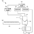
次に、図1乃至図5を用いて、本実施形態の技術について説明する。図1および図2は、本実施形態に係る3次元積層造形装置の構成の概略を示す図であり、材料を散布している状態およびリコータを冷却している状態をそれぞれ表す。
次に、図1乃至図5を用いて、本実施形態の技術について説明する。図1および図2は、本実施形態に係る3次元積層造形装置の構成の概略を示す図であり、材料を散布している状態およびリコータを冷却している状態をそれぞれ表す。
図1および図2に示したように、3次元積層造形装置100は、リコータ101と、温度測定部102と、リコータ冷却制御部103と、冷却ヘッド104とを含む。
リコータ101は、3次元積層造形物130の材料120であるチタン(Ti)などの金属粉体などを造形面上に散布する材料散布機構であり、造形面上を2次元的(XY方向)に駆動する。
リコータ101には、リコータ駆動器111が取り付けられている。リコータ位置制御部150は、リコータ101の動きを制御する。具体的には、リコータ位置制御部150は、リコータ駆動器111に対して制御信号を送信し、制御信号を受信したリコータ駆動器111は、受信した制御信号に基づいて、リコータ101を2次元的に駆動させる。
温度測定部102は、リコータ101の温度を測定する。材料120は、図示しないヒータによる加熱や、電子ビームの照射による予備加熱または加熱などにより、高温状態に維持されている。そして、例えば、造形室がガス充填されている場合や造形室が真空にされている場合には、リコータ101は、充填されているガスの熱や高温に加熱された材料120の輻射熱などにより加熱される。温度測定部102は、リコータ101の温度が所定の温度以上の温度になった場合、所定温度以上になったことを示すアラート信号などをリコータ冷却制御部103に送信する。
アラート信号を受信したリコータ冷却制御部103は、リコータ位置制御部150および昇降制御部143に信号を送信する。そして、図2に示したように、リコータ位置制御部150は、リコータ駆動器111を制御してリコータ101を待機位置(ホーム位置)、つまり、冷却ヘッド104の上部の空間へと移動させる。
また、昇降制御部143は、昇降器142に対して信号を送信する。信号を受信した昇降器142は、冷却ヘッド104を所定の位置まで上昇させて、所定位置に上昇した冷却ヘッド104と待機位置に移動したリコータ101とを接触させる。これにより、リコータ101に蓄えられた熱が冷却ヘッド104に移動するので、リコータ101の温度が下がる。冷却ヘッド104は、例えば、熱伝導率の高い銅(Cu)や銀(Ag)、金(Au)、アルミニウム(Al)、亜鉛(Zn)、ニッケル(Ni)、鉄(Fe)などの金属が代表的であるが、これらには限定されず、これらの合金などであってもよい。
冷却ヘッド104は、リコータ101が待機位置にない場合、例えば、リコータ101が材料120を散布している場合には、冷却媒体141(ヒートシンク)と接触した状態となっている。この状態で、冷却ヘッド104は、リコータ101から伝導され、冷却ヘッド104に蓄えられた熱を放熱している。なお、リコータ101は、材料120を散布していない場合、例えば、材料120に電子ビームなどを照射している間、待機位置(ホーム位置)で待機している。また、リコータ101への材料の120の補充は、リコータ101が待機位置にあり、冷却ヘッド104と接触している間に行ってもよいし、リコータ101の冷却が終了したタイミングで行ってもよい。
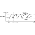
図3は、本実施形態に係る3次元積層造形装置100のリコータ101の温度変化を説明する図である。グラフ301に示したように、材料120の散布を開始したリコータ101の温度は徐々に上昇し、やがて許容最大温度(TCmax)に達する。リコータ101の温度が許容最大温度(TCmax)に達すると、リコータ101は待機位置(ホーム位置)に移動して、冷却ヘッド104と接触して、リコータ101に蓄えられた熱を放熱する。リコータ101が放熱されると、リコータ101の温度は低下し、やがて冷却温度へと到達する(期間t0)。
リコータ101の温度が冷却温度まで低下するとリコータ101は、材料120の散布を再開する。材料120の散布を再開したリコータ101の温度は再び上昇に転じ、再度許容最大温度に達する(期間t1)。リコータ101の温度が許容最大温度に達すると、リコータ101は、再び待機位置へ移動して、冷却ヘッド104と接触して、リコータ101に蓄えられた熱を放熱する。そして、リコータ101は、材料120の散布を再開する。3次元積層造形装置100は、リコータ101の温度が、制御温度範囲内(TCmax~TCmin)に収まるように制御する。このように制御することで、リコータ101の温度が最大温度(Tmax)を超えることがない。
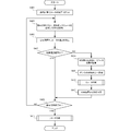
図4は、本実施形態に係る3次元積層造形装置100のリコータ101の冷却手順を説明するフローチャートである。ステップS401において、3次元積層造形装置100は、材料120の散布計画(造形面上におけるリコータ101の位置)を作成する。ステップS403において、3次元積層造形装置100は、作成した散布計画に従って、造形面上でリコータ101を走査して材料120を散布する。ステップS405において、温度測定部102は、あらかじめ定めた時間間隔(定時間隔)でリコータ101の温度を測定する。ステップS407において、3次元積層造形装置100は、リコータ101の温度が制御温度範囲内にあるか否かを判断する。リコータ101の温度が制御温度範囲内にあれば、3次元積層造形装置100は、ステップS409に進む。
ステップS407において、リコータ101の温度が制御温度範囲内になければ、すなわち、リコータ101の温度が、許容最大温度に達するか、または許容最大温度を超えていれば、3次元積層造形装置100は、ステップS413に進む。
ステップS413において、3次元積層造形装置100は、材料120の散布を中断し、リコータ101が材料散布を中断した位置を記憶して、リコータ101を待機位置へと移動させる。つまり、リコータ101の温度が所定の温度を超えたら、材料散布中であっても、リコータ101へのダメージなどを防ぐため、リコータ101を待機位置へと退避させる。
そして、ステップS415において、3次元積層造形装置100は、リコータ101を冷却する。ステップS417において、3次元積層造形装置100は、材料散布を中断した位置から、材料120の散布を再開する。なお、3次元積層造形装置100は、材料散布を中断した場合は、リコータ101による、それまでの材料散布の履歴を記憶する履歴記憶部を備えてもよい。そして、リコータ101が材料散布を再開する場合には、この履歴に基づいて材料散布を再開してもよい。
ステップS409において、3次元積層造形装置100は、作成した散布計画を完遂して、材料120の散布が終了したか否かを判断する。散布計画が未完であり、材料120の散布が終了していなければ、3次元積層造形装置100は、ステップS403に戻り、以降のステップを繰り返す。
散布計画を完遂し、材料120の散布が終了していれば、3次元積層造形装置100は、ステップS411に進み、リコータ101を待機位置へと移動させ、リコータ101の冷却を実施する。
図5は、本実施形態に係る3次元積層造形装置100によるリコータの冷却手順を説明するフローチャートである。ステップS501において、3次元積層造形装置100は、リコータ101を移動させて、待機位置(ホーム位置)に戻す。ステップS503において、3次元積層造形装置100は、昇降器142を上昇させて、リコータ101と冷却ヘッド104とを接触させる。ステップS505において、温度測定部102は、リコータ101の温度を測定する。ステップS507において、3次元積層造形装置100は、リコータ101の温度が冷却温度以下に低下したか否かを判断する。冷却温度以下に低下していないと判断した場合、3次元積層造形装置100は、ステップS505に戻り、以降のステップを繰り返す。
冷却温度以下に低下したと判断した場合、3次元積層造形装置100は、ステップS509へ進む。ステップS509において、3次元積層造形装置100は、昇降器142を降下させて、リコータ101と冷却ヘッド104とが離れるようにする。
本実施形態によれば、リコータを冷却する冷却器や冷却パイプがないので、2次元的に駆動するリコータを簡易な構造で冷却できる。また、リコータの動きが制限されず、位置制御の精度が向上する。さらに、リコータに余分な装備が付いていないので、リコータを軽量化することができ、リコータを高速で動かすことができる。リコータの温度を一定の範囲以内に維持でき、リコータが待機位置にあるときに、材料を補充することができるのでタイムロスが減少する。
[第2実施形態]
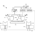
次に本発明の第2実施形態に係る3次元積層造形装置について、図7および図8を用いて説明する。図7は、本実施形態に係る3次元積層造形装置700の構成の概略を説明するための図である。本実施形態に係る3次元積層造形装置700は、上記第1実施形態と比べると、冷却ヘッドを2つ有する点で異なる。その他の構成および動作は、第1実施形態と同様であるため、同じ構成および動作については同じ符号を付してその詳しい説明を省略する。
次に本発明の第2実施形態に係る3次元積層造形装置について、図7および図8を用いて説明する。図7は、本実施形態に係る3次元積層造形装置700の構成の概略を説明するための図である。本実施形態に係る3次元積層造形装置700は、上記第1実施形態と比べると、冷却ヘッドを2つ有する点で異なる。その他の構成および動作は、第1実施形態と同様であるため、同じ構成および動作については同じ符号を付してその詳しい説明を省略する。
3次元積層造形装置700は、冷却ヘッド704をさらに備える。つまり、3次元積層造形装置は、リコータ101の待機位置(ホーム位置)を2か所有する。そして、温度測定部102による温度測定の結果、リコータ101の温度が所定の温度(許容最大温度)以上の温度になった場合、所定の温度以上になったことを示すアラート信号がリコータ冷却制御部103に送信される。
アラート信号を受信したリコータ冷却制御部103は、リコータ101の位置に基づいて、2つある待機位置のうちリコータ101の現在位置からの距離が近い方、すなわち、リコータ101の移動時間が短い方の待機位置までリコータ101を移動させる。
例えば、冷却ヘッド704側の待機位置が近ければ、リコータ冷却制御部103は、リコータ位置制御部150および昇降制御部143を制御して、リコータ101と冷却ヘッド704とを接触させる。なお、リコータ101が、両待機位置の中間に位置している場合などは、待機位置に優先順位を付けておき、優先順位の高い待機位置へ移動させてもよい。
あるいは、リコータ101の現在位置にかかわらず、2つある待機位置に交互に移動させてもよい。このように制御することにより、冷却ヘッド104(704)を冷却媒体141(741)で確実に冷却することができ、一方の冷却ヘッド104(704)が連続して使われることがないので、十分な放熱効果が期待できる。
図8は、本実施形態に係る3次元積層造形装置700の冷却手順を説明するフローチャートである。ステップS801において、3次元積層造形装置700は、リコータ101の現在位置に基づいて、近い方の待機位置へリコータ101を移動させる。
本実施形態によれば、より迅速にリコータを冷却することができ、3次元積層造形物の造形時間を短縮することができる。
[第3実施形態]
次に本発明の第3実施形態に係る3次元積層造形装置について、図9および図10を用いて説明する。図9は、本実施形態に係る3次元積層造形装置900の構成の概略を説明するための図である。本実施形態に係る3次元積層造形装置900は、上記第2実施形態と比べると、リコータを2つ有する点で異なる。その他の構成および動作は、第2実施形態と同様であるため、同じ構成および動作については同じ符号を付してその詳しい説明を省略する。
次に本発明の第3実施形態に係る3次元積層造形装置について、図9および図10を用いて説明する。図9は、本実施形態に係る3次元積層造形装置900の構成の概略を説明するための図である。本実施形態に係る3次元積層造形装置900は、上記第2実施形態と比べると、リコータを2つ有する点で異なる。その他の構成および動作は、第2実施形態と同様であるため、同じ構成および動作については同じ符号を付してその詳しい説明を省略する。
3次元積層造形装置900は、リコータ901をさらに備える。これにより、例えば、一方のリコータ101(リコータ901)を待機位置で冷却している場合には、他方のリコータ901(リコータ101)が材料を散布してもよい。また、2つのリコータ101,901を用いて同種材料を散布すれば、材料の散布時間を短縮でき、3次元積層造形物の造形時間を短縮できる。さらに、2つのリコータ101,901を用いて、異種材料を散布することもできるので、異種材料からなる3次元積層造形物を造形することもできる。
本実施形態によれば、2つのリコータで材料を散布できるので、材料の散布時間を短縮でき、3次元積層造形物の造形時間を短縮できる。さらに、2つのリコータを備えるので、複数の材料を散布でき、それぞれのリコータも冷却できる。
[他の実施形態]
以上、実施形態を参照して本願発明を説明したが、本願発明は上記実施形態に限定されるものではない。本願発明の構成や詳細には、本願発明のスコープ内で当業者が理解し得る様々な変更をすることができる。また、それぞれの実施形態に含まれる別々の特徴を如何様に組み合わせたシステムまたは装置も、本発明の範疇に含まれる。
以上、実施形態を参照して本願発明を説明したが、本願発明は上記実施形態に限定されるものではない。本願発明の構成や詳細には、本願発明のスコープ内で当業者が理解し得る様々な変更をすることができる。また、それぞれの実施形態に含まれる別々の特徴を如何様に組み合わせたシステムまたは装置も、本発明の範疇に含まれる。
また、本発明は、複数の機器から構成されるシステムに適用されてもよいし、単体の装置に適用されてもよい。さらに、本発明は、実施形態の機能を実現する情報処理プログラムが、システムあるいは装置に直接あるいは遠隔から供給される場合にも適用可能である。したがって、本発明の機能をコンピュータで実現するために、コンピュータにインストールされるプログラム、あるいはそのプログラムを格納した媒体、そのプログラムをダウンロードさせるWWW(World Wide Web)サーバも、本発明の範疇に含まれる。特に、少なくとも、上述した実施形態に含まれる処理ステップをコンピュータに実行させるプログラムを格納した非一時的コンピュータ可読媒体(non-transitory computer readable medium)は本発明の範疇に含まれる。
Claims (7)
- 3次元積層造形物の材料を散布する少なくとも1つの材料散布手段と、
前記材料散布手段の温度を測定する温度測定手段と、
前記材料を散布しない場合に前記材料散布手段が待機する待機位置に設けられ、前記材料散布手段を冷却する少なくとも1つの冷却手段と、
前記材料散布手段を制御する制御手段と、
を備え、
前記制御手段は、前記散布手段を前記待機位置に移動させ、前記材料散布手段と前記冷却手段とを接触させる3次元積層造形装置。 - 前記制御手段は、前記材料散布手段による前記材料の散布が終了した場合、前記材料散布手段を前記待機位置へと移動させ、前記材料散布手段と前記冷却手段とを接触させる請求項1に記載の3次元積層造形装置。
- 前記制御手段は、材料散布中に前記材料散布手段の温度が所定温度を超えた場合、材料散布を中断し、前記材料散布手段を前記待機位置へと移動させ、前記材料散布手段と前記冷却手段とを接触させる請求項1に記載の3次元積層造形装置。
- 前記材料散布手段による材料散布の履歴を記憶する履歴記憶手段をさらに備え、
材料散布を中断した場合、前記制御手段は、前記履歴に基づいて材料散布を再開する請求項3に記載の3次元積層造形装置。 - 前記材料散布手段に前記材料を補充する材料補充手段をさらに備え、
前記材料補充手段は、前記材料散布手段が前記待機位置にあり、前記材料散布手段と前記冷却手段とが接触している間に前記材料を補充する請求項1乃至4のいずれか1項に記載の3次元積層造形装置。 - 材料散布手段により、材料を散布する材料散布ステップと、
前記材料散布手段の温度を測定する温度測定ステップと、
前記材料を散布しない場合に前記材料散布手段が待機する待機位置に設けられた前記材料散布手段の冷却手段と、前記材料散布手段とを接触させるように前記材料散布手段の動きを制御する制御ステップと、
を含む3次元積層造形装置の制御方法。 - 材料散布手段により、材料を散布する材料散布ステップと、
前記材料散布手段の温度を測定する温度測定ステップと、
前記材料を散布しない場合に前記材料散布手段が待機する待機位置に設けられた前記材料散布手段を冷却する冷却手段と、前記材料散布手段とを接触させるように前記材料散布手段の動きを制御する制御ステップと、
をコンピュータに実行させる3次元積層造形装置の制御プログラム。
Priority Applications (4)
| Application Number | Priority Date | Filing Date | Title |
|---|---|---|---|
| US15/119,606 US10131015B2 (en) | 2015-12-25 | 2015-12-25 | Three-dimensional laminating and shaping apparatus, control method of three-dimensional laminating and shaping apparatus, and control program of three-dimensional laminating and shaping apparatus |
| JP2016510872A JP6118455B1 (ja) | 2015-12-25 | 2015-12-25 | 3次元積層造形装置、3次元積層造形装置の制御方法および3次元積層造形装置の制御プログラム |
| PCT/JP2015/086305 WO2017109965A1 (ja) | 2015-12-25 | 2015-12-25 | 3次元積層造形装置、3次元積層造形装置の制御方法および3次元積層造形装置の制御プログラム |
| EP15899115.8A EP3210701A4 (en) | 2015-12-25 | 2015-12-25 | Three-dimensional laminate molding device, control method of three-dimensional laminate molding device, and control program of three-dimensional laminate molding device |
Applications Claiming Priority (1)
| Application Number | Priority Date | Filing Date | Title |
|---|---|---|---|
| PCT/JP2015/086305 WO2017109965A1 (ja) | 2015-12-25 | 2015-12-25 | 3次元積層造形装置、3次元積層造形装置の制御方法および3次元積層造形装置の制御プログラム |
Publications (1)
| Publication Number | Publication Date |
|---|---|
| WO2017109965A1 true WO2017109965A1 (ja) | 2017-06-29 |
Family
ID=58666829
Family Applications (1)
| Application Number | Title | Priority Date | Filing Date |
|---|---|---|---|
| PCT/JP2015/086305 Ceased WO2017109965A1 (ja) | 2015-12-25 | 2015-12-25 | 3次元積層造形装置、3次元積層造形装置の制御方法および3次元積層造形装置の制御プログラム |
Country Status (4)
| Country | Link |
|---|---|
| US (1) | US10131015B2 (ja) |
| EP (1) | EP3210701A4 (ja) |
| JP (1) | JP6118455B1 (ja) |
| WO (1) | WO2017109965A1 (ja) |
Cited By (1)
| Publication number | Priority date | Publication date | Assignee | Title |
|---|---|---|---|---|
| JP2018058281A (ja) * | 2016-10-06 | 2018-04-12 | 株式会社アスペクト | 粉末床溶融結合装置 |
Families Citing this family (2)
| Publication number | Priority date | Publication date | Assignee | Title |
|---|---|---|---|---|
| US11426818B2 (en) | 2018-08-10 | 2022-08-30 | The Research Foundation for the State University | Additive manufacturing processes and additively manufactured products |
| WO2022140198A1 (en) * | 2020-12-23 | 2022-06-30 | Nikon Corporation | Systems and methods of powder delivery for additive manufacturing |
Citations (4)
| Publication number | Priority date | Publication date | Assignee | Title |
|---|---|---|---|---|
| JP2007021747A (ja) | 2005-07-12 | 2007-02-01 | Imageom:Kk | 粉末焼結造形装置及び粉末焼結造形方法 |
| JP2012011610A (ja) * | 2010-06-30 | 2012-01-19 | Hitachi Kokusai Electric Inc | 光造形装置 |
| JP2015104837A (ja) * | 2013-11-29 | 2015-06-08 | 東京エレクトロン株式会社 | 積層造形装置、積層造形方法及び移動部 |
| JP2015193135A (ja) * | 2014-03-31 | 2015-11-05 | 日本電子株式会社 | 三次元積層造形装置 |
Family Cites Families (3)
| Publication number | Priority date | Publication date | Assignee | Title |
|---|---|---|---|---|
| US20050104241A1 (en) * | 2000-01-18 | 2005-05-19 | Objet Geometried Ltd. | Apparatus and method for three dimensional model printing |
| NL2009446A (en) * | 2011-10-12 | 2013-04-15 | Asml Netherlands Bv | Radiation beam welding method, body and lithographic apparatus. |
| EP2928670B1 (en) | 2012-12-06 | 2016-05-25 | Materialise N.V. | Systems and methods of controlling a temperature differential in the manufacture of objects |
-
2015
- 2015-12-25 WO PCT/JP2015/086305 patent/WO2017109965A1/ja not_active Ceased
- 2015-12-25 US US15/119,606 patent/US10131015B2/en not_active Expired - Fee Related
- 2015-12-25 EP EP15899115.8A patent/EP3210701A4/en not_active Withdrawn
- 2015-12-25 JP JP2016510872A patent/JP6118455B1/ja active Active
Patent Citations (4)
| Publication number | Priority date | Publication date | Assignee | Title |
|---|---|---|---|---|
| JP2007021747A (ja) | 2005-07-12 | 2007-02-01 | Imageom:Kk | 粉末焼結造形装置及び粉末焼結造形方法 |
| JP2012011610A (ja) * | 2010-06-30 | 2012-01-19 | Hitachi Kokusai Electric Inc | 光造形装置 |
| JP2015104837A (ja) * | 2013-11-29 | 2015-06-08 | 東京エレクトロン株式会社 | 積層造形装置、積層造形方法及び移動部 |
| JP2015193135A (ja) * | 2014-03-31 | 2015-11-05 | 日本電子株式会社 | 三次元積層造形装置 |
Non-Patent Citations (1)
| Title |
|---|
| See also references of EP3210701A4 |
Cited By (1)
| Publication number | Priority date | Publication date | Assignee | Title |
|---|---|---|---|---|
| JP2018058281A (ja) * | 2016-10-06 | 2018-04-12 | 株式会社アスペクト | 粉末床溶融結合装置 |
Also Published As
| Publication number | Publication date |
|---|---|
| US10131015B2 (en) | 2018-11-20 |
| JP6118455B1 (ja) | 2017-04-19 |
| EP3210701A4 (en) | 2018-09-26 |
| US20180015564A1 (en) | 2018-01-18 |
| JPWO2017109965A1 (ja) | 2017-12-21 |
| EP3210701A1 (en) | 2017-08-30 |
Similar Documents
| Publication | Publication Date | Title |
|---|---|---|
| US11020822B2 (en) | Active cooling of additive manufacturing process | |
| CN109562569B (zh) | 构建材料颗粒分层 | |
| US9573224B2 (en) | System and method for determining beam power level along an additive deposition path | |
| JP6118455B1 (ja) | 3次元積層造形装置、3次元積層造形装置の制御方法および3次元積層造形装置の制御プログラム | |
| US7326377B2 (en) | Solid-free-form fabrication process and apparatus including in-process workpiece cooling | |
| US9767224B2 (en) | Systems and methods for designing and fabricating contact-free support structures for overhang geometries of parts in powder-bed metal additive manufacturing | |
| US10010936B2 (en) | Systems and methods for designing and fabricating support structures for overhang geometries of parts in additive manufacturing | |
| CN110802300A (zh) | 一种电弧增材制造过程中成形精度与质量控制的设备与方法 | |
| WO2015031453A1 (en) | Systems and methods for additive manufacturing of three dimensional structures | |
| KR102284632B1 (ko) | 대규모 금속 성형 | |
| CN103056364A (zh) | 添加制造原地应力释放 | |
| CN104959604A (zh) | 一种成形区域温度梯度可控的高能束选区熔化方法与设备 | |
| EP3332905A1 (en) | Metal additive system | |
| US11260453B2 (en) | Method for additive production, component, and apparatus for additive production | |
| EP4232261B1 (en) | Print and recoat assembly for additive manufacturing system and method for using the same | |
| US11027488B2 (en) | Three-dimensional laminating and shaping apparatus, control method of three-dimensional laminating and shaping apparatus, control program of three-dimensional laminating and shaping apparatus, and jig | |
| JP2019521007A (ja) | 3d印刷 | |
| US9700953B2 (en) | Adaptive welding apparatus, control system, and method of controlling an adaptive welding apparatus | |
| JP6604795B2 (ja) | 離型剤塗布装置 | |
| JP6405186B2 (ja) | コーティング剤の塗布装置、および塗布方法 | |
| JP6010593B2 (ja) | 金型加熱装置 | |
| KR20140131306A (ko) | 마찰교반용접 장치 및 그 방법 | |
| JP7072652B2 (ja) | プレートを熱処理する炉装置のための温度調節ユニット | |
| JP2019057595A5 (ja) | ||
| US20210154917A1 (en) | Additive manufacturing method |
Legal Events
| Date | Code | Title | Description |
|---|---|---|---|
| ENP | Entry into the national phase |
Ref document number: 2016510872 Country of ref document: JP Kind code of ref document: A |
|
| WWE | Wipo information: entry into national phase |
Ref document number: 15119606 Country of ref document: US |
|
| REEP | Request for entry into the european phase |
Ref document number: 2015899115 Country of ref document: EP |
|
| WWE | Wipo information: entry into national phase |
Ref document number: 2015899115 Country of ref document: EP |
|
| NENP | Non-entry into the national phase |
Ref country code: DE |