WO2017110120A1 - 空圧システム運転制御装置および制御方法 - Google Patents
空圧システム運転制御装置および制御方法 Download PDFInfo
- Publication number
- WO2017110120A1 WO2017110120A1 PCT/JP2016/070926 JP2016070926W WO2017110120A1 WO 2017110120 A1 WO2017110120 A1 WO 2017110120A1 JP 2016070926 W JP2016070926 W JP 2016070926W WO 2017110120 A1 WO2017110120 A1 WO 2017110120A1
- Authority
- WO
- WIPO (PCT)
- Prior art keywords
- value
- air
- set value
- air compressor
- piping network
- Prior art date
- Legal status (The legal status is an assumption and is not a legal conclusion. Google has not performed a legal analysis and makes no representation as to the accuracy of the status listed.)
- Ceased
Links
Images






Classifications
-
- F—MECHANICAL ENGINEERING; LIGHTING; HEATING; WEAPONS; BLASTING
- F04—POSITIVE - DISPLACEMENT MACHINES FOR LIQUIDS; PUMPS FOR LIQUIDS OR ELASTIC FLUIDS
- F04B—POSITIVE-DISPLACEMENT MACHINES FOR LIQUIDS; PUMPS
- F04B49/00—Control, e.g. of pump delivery, or pump pressure of, or safety measures for, machines, pumps, or pumping installations, not otherwise provided for, or of interest apart from, groups F04B1/00 - F04B47/00
- F04B49/06—Control using electricity
-
- F—MECHANICAL ENGINEERING; LIGHTING; HEATING; WEAPONS; BLASTING
- F04—POSITIVE - DISPLACEMENT MACHINES FOR LIQUIDS; PUMPS FOR LIQUIDS OR ELASTIC FLUIDS
- F04B—POSITIVE-DISPLACEMENT MACHINES FOR LIQUIDS; PUMPS
- F04B49/00—Control, e.g. of pump delivery, or pump pressure of, or safety measures for, machines, pumps, or pumping installations, not otherwise provided for, or of interest apart from, groups F04B1/00 - F04B47/00
- F04B49/06—Control using electricity
- F04B49/065—Control using electricity and making use of computers
-
- F—MECHANICAL ENGINEERING; LIGHTING; HEATING; WEAPONS; BLASTING
- F04—POSITIVE - DISPLACEMENT MACHINES FOR LIQUIDS; PUMPS FOR LIQUIDS OR ELASTIC FLUIDS
- F04B—POSITIVE-DISPLACEMENT MACHINES FOR LIQUIDS; PUMPS
- F04B49/00—Control, e.g. of pump delivery, or pump pressure of, or safety measures for, machines, pumps, or pumping installations, not otherwise provided for, or of interest apart from, groups F04B1/00 - F04B47/00
- F04B49/08—Regulating by delivery pressure
-
- F—MECHANICAL ENGINEERING; LIGHTING; HEATING; WEAPONS; BLASTING
- F04—POSITIVE - DISPLACEMENT MACHINES FOR LIQUIDS; PUMPS FOR LIQUIDS OR ELASTIC FLUIDS
- F04B—POSITIVE-DISPLACEMENT MACHINES FOR LIQUIDS; PUMPS
- F04B49/00—Control, e.g. of pump delivery, or pump pressure of, or safety measures for, machines, pumps, or pumping installations, not otherwise provided for, or of interest apart from, groups F04B1/00 - F04B47/00
- F04B49/10—Other safety measures
-
- F—MECHANICAL ENGINEERING; LIGHTING; HEATING; WEAPONS; BLASTING
- F04—POSITIVE - DISPLACEMENT MACHINES FOR LIQUIDS; PUMPS FOR LIQUIDS OR ELASTIC FLUIDS
- F04B—POSITIVE-DISPLACEMENT MACHINES FOR LIQUIDS; PUMPS
- F04B49/00—Control, e.g. of pump delivery, or pump pressure of, or safety measures for, machines, pumps, or pumping installations, not otherwise provided for, or of interest apart from, groups F04B1/00 - F04B47/00
- F04B49/10—Other safety measures
- F04B49/106—Responsive to pumped volume
-
- F—MECHANICAL ENGINEERING; LIGHTING; HEATING; WEAPONS; BLASTING
- F04—POSITIVE - DISPLACEMENT MACHINES FOR LIQUIDS; PUMPS FOR LIQUIDS OR ELASTIC FLUIDS
- F04B—POSITIVE-DISPLACEMENT MACHINES FOR LIQUIDS; PUMPS
- F04B2203/00—Motor parameters
- F04B2203/02—Motor parameters of rotating electric motors
- F04B2203/0209—Rotational speed
-
- F—MECHANICAL ENGINEERING; LIGHTING; HEATING; WEAPONS; BLASTING
- F04—POSITIVE - DISPLACEMENT MACHINES FOR LIQUIDS; PUMPS FOR LIQUIDS OR ELASTIC FLUIDS
- F04B—POSITIVE-DISPLACEMENT MACHINES FOR LIQUIDS; PUMPS
- F04B2205/00—Fluid parameters
- F04B2205/05—Pressure after the pump outlet
-
- F—MECHANICAL ENGINEERING; LIGHTING; HEATING; WEAPONS; BLASTING
- F04—POSITIVE - DISPLACEMENT MACHINES FOR LIQUIDS; PUMPS FOR LIQUIDS OR ELASTIC FLUIDS
- F04B—POSITIVE-DISPLACEMENT MACHINES FOR LIQUIDS; PUMPS
- F04B2205/00—Fluid parameters
- F04B2205/06—Pressure in a (hydraulic) circuit
-
- F—MECHANICAL ENGINEERING; LIGHTING; HEATING; WEAPONS; BLASTING
- F04—POSITIVE - DISPLACEMENT MACHINES FOR LIQUIDS; PUMPS FOR LIQUIDS OR ELASTIC FLUIDS
- F04B—POSITIVE-DISPLACEMENT MACHINES FOR LIQUIDS; PUMPS
- F04B2205/00—Fluid parameters
- F04B2205/09—Flow through the pump
-
- F—MECHANICAL ENGINEERING; LIGHTING; HEATING; WEAPONS; BLASTING
- F04—POSITIVE - DISPLACEMENT MACHINES FOR LIQUIDS; PUMPS FOR LIQUIDS OR ELASTIC FLUIDS
- F04B—POSITIVE-DISPLACEMENT MACHINES FOR LIQUIDS; PUMPS
- F04B2207/00—External parameters
- F04B2207/02—External pressure
-
- F—MECHANICAL ENGINEERING; LIGHTING; HEATING; WEAPONS; BLASTING
- F05—INDEXING SCHEMES RELATING TO ENGINES OR PUMPS IN VARIOUS SUBCLASSES OF CLASSES F01-F04
- F05B—INDEXING SCHEME RELATING TO WIND, SPRING, WEIGHT, INERTIA OR LIKE MOTORS, TO MACHINES OR ENGINES FOR LIQUIDS COVERED BY SUBCLASSES F03B, F03D AND F03G
- F05B2270/00—Control
- F05B2270/10—Purpose of the control system
- F05B2270/101—Purpose of the control system to control rotational speed (n)
-
- F—MECHANICAL ENGINEERING; LIGHTING; HEATING; WEAPONS; BLASTING
- F05—INDEXING SCHEMES RELATING TO ENGINES OR PUMPS IN VARIOUS SUBCLASSES OF CLASSES F01-F04
- F05B—INDEXING SCHEME RELATING TO WIND, SPRING, WEIGHT, INERTIA OR LIKE MOTORS, TO MACHINES OR ENGINES FOR LIQUIDS COVERED BY SUBCLASSES F03B, F03D AND F03G
- F05B2270/00—Control
- F05B2270/30—Control parameters, e.g. input parameters
- F05B2270/301—Pressure
- F05B2270/3013—Outlet
-
- F—MECHANICAL ENGINEERING; LIGHTING; HEATING; WEAPONS; BLASTING
- F05—INDEXING SCHEMES RELATING TO ENGINES OR PUMPS IN VARIOUS SUBCLASSES OF CLASSES F01-F04
- F05B—INDEXING SCHEME RELATING TO WIND, SPRING, WEIGHT, INERTIA OR LIKE MOTORS, TO MACHINES OR ENGINES FOR LIQUIDS COVERED BY SUBCLASSES F03B, F03D AND F03G
- F05B2270/00—Control
- F05B2270/30—Control parameters, e.g. input parameters
- F05B2270/327—Rotor or generator speeds
Definitions
- the present invention relates to a pneumatic system operation control apparatus and control method provided with an air compressor controlled by a variable speed apparatus such as an inverter.
- the discharge pressure of the air compressor is set in consideration of the maximum pressure loss of the piping network so that the supply pressure to the end device is equal to or higher than the initial pressure. Thereby, compressed air more than a desired pressure can be obtained in the terminal device.
- the discharge pressure of the air compressor remains set high despite the fact that the pressure loss of the piping network is small, so the air compressor will be driven more than necessary, Excessive power will be consumed.
- Patent Document 1 the supply pressure to the end device and the discharge pressure of the air compressor are measured, and the supply pressure to the end device is determined according to the air flow rate at the end device.
- a compressor operation control device is disclosed.
- the past operating condition history of the air compressor is stored by the learning function, and the past measured values of the air compressor power consumption, the air compressor discharge pressure, and the end device supply pressure are stored in the past.
- the operating condition history there is disclosed a technique for determining operating conditions of an air compressor for supplying compressed air having a pressure equal to or higher than a desired pressure to an end device while reducing power consumption of the air compressor.
- the air compressor operation control device disclosed in Patent Document 1 it is possible to supply compressed air having a pressure equal to or higher than a desired pressure to a terminal device while reducing the power consumption of the air compressor.
- the supply pressure to the terminal equipment changes with a delay with respect to the change in the discharge pressure of the air compressor, and the delay time is about several tens of seconds.
- the end equipment supply pressure responds with a delay to the discharge pressure of the air compressor, generally, when the air compressor is controlled so that the end equipment supply pressure becomes a constant pressure, the supply pressure to the end equipment fluctuates. .
- the rotation speed of the electric motor that drives the air compressor is controlled by PID control so as to suppress fluctuations in the supply pressure.
- the volume of the piping varies depending on the piping layout conditions in which the air compressor is installed, and the piping layout changes after the installation due to the additional installation of end devices. That is, in the air compressor operation control device disclosed in Patent Document 1, it is difficult to adjust the control set value according to the installation state of the piping layout, and the supply pressure may fluctuate.
- an object of the present invention is to provide an air compressor operation control device for supplying compressed air having a pressure equal to or higher than a desired pressure to a terminal device while reducing power consumption of the air compressor.
- the present invention provides: Based on the measured value of the discharge pressure of the air compressor and the measured value of the supply pressure to the end device, the air compressor for variably controlling the rotation speed of the motor for driving the air compressor so that the supply pressure to the end device is constant.
- An air piping network which is a pressure system operation control device, wherein the discharge pressure measurement value, a measurement value storage unit for storing the supply pressure measurement value, and a path for supplying compressed air from the air compressor to the end device
- An air piping network model input unit for inputting an air piping network model composed of data for calculating the air flow in the air piping network, and an air piping network model storage for storing the air piping network model Section, the discharge pressure measurement value, the supply pressure measurement value, and the air piping network model.
- a terminal device flow rate calculation unit for calculating the air flow rate, a terminal device flow rate storage unit for storing the air flow rate, a control setting value for variably controlling the rotational speed of the driving motor of the air compressor, From the air flow rate and the air piping network model, a control set value calculation unit that calculates an update value of the control set value, a control set value storage unit that stores the update value, and the air compressor from the update value And a control set value update command value creating unit for creating a command value for updating a control set value for variably controlling the rotational speed of the drive motor.
- the present invention it is not necessary for the user to input the operating condition of the air compressor in advance, and the consumption of the air compressor is suppressed while suppressing the fluctuation of the supply pressure to the end device according to the installation status of the piping layout.
- Compressed air having a pressure equal to or higher than a desired pressure can be supplied to the end device while reducing power.
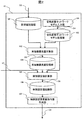
- FIG. 1 is a schematic configuration diagram of a pneumatic system operation control device according to Embodiment 1.
- FIG. It is a schematic block diagram of the control setting value update part which concerns on Example 1.
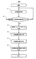
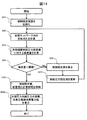
- FIG. It is a processing procedure flow of the control setting value update in the pneumatic system operation control apparatus which concerns on Example 1.
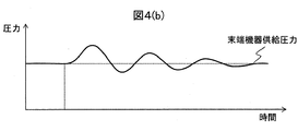
- FIG. It is time series data of the compressed air pressure of the air compressor discharge part which concerns on Example 1, and the compressed air pressure supplied to a terminal device. It is time series data of the compressed air pressure of the air compressor discharge part which concerns on Example 1, and the compressed air pressure supplied to a terminal device. It is the calculated value of the compressed air flow rate supplied to the terminal device which concerns on Example 1.
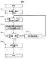
- FIG. 4 is a detailed flow of a process of a control set value calculation process according to the first embodiment.
- FIG. 10 is a schematic configuration diagram of a control set value update unit according to a second embodiment. 12 is a detailed flow of a process of a control set value calculation process according to the second embodiment. It is a figure which shows the relationship of the minimum value of the terminal equipment supply pressure setting value which concerns on Example 2, a required pressure, and a terminal device supply pressure calculation value.
- FIG. 10 is a schematic configuration diagram of a control set value update unit according to a third embodiment. 10 is a detailed flow of a process of a control set value calculation process according to the third embodiment. It is the figure which displayed the fluctuation
- FIG. 1 is a schematic configuration diagram of a pneumatic system operation control apparatus according to the first embodiment.
- the 1 includes an air compressor unit 1, an air piping network 7, a terminal device 8, a terminal device pressure sensor 9, and a control set value update unit 10.
- the air compressor unit 1 compresses the air A sucked from the atmosphere and discharges the compressed air.
- the air compressor unit 1 includes an air compressor body 2, an air compressor discharge unit pressure sensor 3, a control device 4, a variable speed device 5, and an electric motor 6. Below, schematic structure of the air compressor unit 1 is demonstrated.
- the air compressor body 2 sucks air A and compresses it.
- the air compressor discharge part pressure sensor 3 measures the pressure of the compressor air discharged from the air compressor body 2. The measured pressure value is output to the control device 4 and the control set value update unit 10.
- the control device 4 receives the pressure measurement value of the air compressor discharge section pressure sensor 3 and the pressure measurement value of the end equipment section pressure sensor 9 as input, and the supply pressure of the compressor air to the end equipment 8 becomes the required pressure P0 or more.
- the rotation speed of the electric motor 6 is controlled, and the rotation speed command value for the electric motor 6 is calculated and output.
- a specific calculation method for controlling the rotation speed of the electric motor 6 can be realized by a method described in, for example, Japanese Patent Application Laid-Open No. 2010-24845.
- control device 4 outputs the current value of the control set value D1 for controlling the rotation speed of the electric motor 6 to the control set value update unit 10, and the control set value update command output by the control set value update unit 10 Based on the value D2, the current value D1 of the control set value is updated.
- the variable speed device 5 outputs the electric power necessary for rotating the electric motor 6 at the designated rotational speed with the rotational speed command value as an input.
- the electric motor 6 is coupled to the air compressor main body 2 via a rotating shaft, and rotates based on the input electric power to drive the air compressor main body 2.
- the air piping network 7 is composed of devices such as an air layer, a filter, a dryer, piping, an elbow, a branch, and a valve.
- the compressed air discharged from the air compressor unit 1 is transferred to the end device 8 through the air piping network 7. Supplied.
- the terminal device 8 is a device used in the manufacturing process of the factory, such as a pneumatic tool, an air press, an air brake, a spray gun, and the like, and is driven using compressed air supplied through the air piping network 7 as a power source.
- the terminal device pressure sensor 9 measures the pressure of the compressor air supplied to the terminal device 8. The measured pressure value is output to the control device 4 and the control set value update unit 10.
- the control set value update unit 10 receives the pressure measurement value of the air compressor discharge unit pressure sensor 3 and the pressure measurement value of the end device unit pressure sensor 9 as inputs, and outputs a control set value update command value.
- the control device 4 receives the control set value update command value and updates the control set value.
- the control set value update unit 10 includes a measured value storage unit 100, an air piping network model input unit 101, an air piping network model storage unit 102, an end device flow rate calculation unit 103, an end device flow rate storage unit 104, and a control set value calculation unit 105. , A control set value storage unit 106 and a control set value update command value creation unit 107.
- the measurement value storage unit 100 is configured by a memory or a hard disk, and stores the pressure measurement value D3 acquired by the air compressor discharge unit pressure sensor 3 and the terminal device unit pressure sensor 9.
- an air piping network model D4 is output. Specifically, data defining connection relations between devices constituting the air piping network 7, data defining device attributes (for example, piping length, piping diameter, etc. for piping), and air compressor It is data for calculating the discharge air pressure of the unit 1.
- the air piping network model storage unit 102 includes a memory and a hard disk, and stores the air piping network model D4 output from the air piping network model input unit 101.
- the terminal device flow rate calculation unit 103 calculates the air flow in the air piping network 7 from the pressure measurement value D3 and the air piping network model D4, and outputs a terminal device flow rate D5 that is a compressed air flow rate supplied to the terminal device. .
- a specific calculation method for calculating the air flow in the air pipe network 7 see, for example, the document “GP Greyvenstein (2002), An implicit method for the analysis of transient flows in pipe networks, International Journa” l for Numerical Methods in Engineering, vol. 53, issue 5, pp. 1127-1143 ”.
- the terminal device flow rate storage unit 104 includes a memory and a hard disk, and stores the terminal device flow rate D5 output from the terminal device flow rate calculation unit 103.
- the control set value calculation unit 105 calculates the control set value from the control set value D1, the air piping network model D4, and the end device flow rate D5 so as to suppress fluctuations in the supply pressure to the end device, and updates the control set value. Output as value D6.
- a specific calculation method of the control set value update value D6 will be described later with reference to FIGS.
- the control set value storage unit 106 includes a memory and a hard disk, and stores the control set value update value D6 output from the control set value calculation unit 105.
- the control set value update command value creating unit 107 receives the control set value update value D6 and outputs a control set value update command value D2 for updating the control set value D1 of the control device 4.
- FIG. 3 illustrates a processing procedure for updating the control set value in the pneumatic system operation control apparatus according to the first embodiment.
- the measurement value storage unit 100 stores the pressure measurement value D3 acquired by the air compressor discharge unit pressure sensor 3 and the terminal device unit pressure sensor 9 in a memory or a hard disk.
- step S2 control set value timing determination process
- the control set value update unit 10 determines whether or not the current time coincides with a preset control set value update timing. If the determination result is Yes, the process proceeds to step S3 (piping network model generation process), and if No, the process of step S1 is continued.
- step S3 piping network model generation process
- step S1 and S2 time-series data of the compressed air pressure of the air compressor discharge unit and the compressed air pressure supplied to the terminal device 8 shown in FIG. 4 is obtained.
- step S3 piping network model generation process
- the air piping network model input unit 101 inputs data necessary for calculating the flow of compressed air in the air piping network 7 and outputs an air piping network model D4. To do.
- the air piping network model D4 is stored in a memory or a hard disk by the air piping network model storage unit 102.
- step S4 end device flow rate calculation process
- the end device flow rate calculation unit 103 calculates the air flow in the air pipe network 7 from the pressure measurement value D3 and the air pipe network model D4, and the compression supplied to the end equipment.
- the terminal device flow rate D5 which is an air flow rate is output.
- FIG. 5 shows the end device output by the end device flow rate calculation unit 103 with respect to the time series data of the compressed air pressure of the air compressor discharge unit and the compressed air pressure supplied to the end device 8 shown in FIG. It is an example of the flow rate D5.
- the terminal device flow rate D5 is stored in a memory or a hard disk by the terminal device flow rate storage unit 104.
- step S5 control set value calculation process
- the control set value calculation unit 105 suppresses fluctuations in the supply pressure to the end device from the control set value D1, the air piping network model D4, and the end device flow rate D5.
- the control set value update value D6 is calculated. Details of the processing in step S5 will be described later with reference to FIGS.
- the control set value update value D6 is stored in the memory or hard disk by the control set value storage unit 106.
- step S6 control set value update command value output process
- the control set value update command value creation unit 107 receives the control set value update value D6 and inputs a control setting for updating the control set value D1 of the control device 4.
- the value update command value D2 is output.
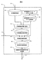
- step S5 includes six processes of steps S51 to S56.
- step S51 control set value initialization process
- the control set value calculation unit 105 substitutes the control set value D1 for the control set value update value D6 and initializes it.
- the control set value D1 becomes three parameters of the proportional gain KP, the integration time TI, and the differential time TD, and the control set value update value D6 Is substituted with the current values of these three parameters.
- step S52 the control set value calculation unit 105 calculates the air flow in the air pipe network 7 from the air pipe network model D4, the terminal device flow rate D5, and the control set value update value D6.
- the terminal device supply pressure calculation value PC which is the compressed air pressure supplied to the terminal device 8 is output.
- step S53 pressure deviation amount calculation process
- the control set value calculation unit 105 uses the terminal device supply pressure calculation value PC for the end device supply pressure set value PS as an index for evaluating the amount of fluctuation in the supply pressure to the end device 8.
- the deviation amount E is calculated.
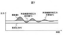
- the deviation amount E is an area value indicated by hatching in the drawing shown in FIG. 7, and is calculated from the following equation.
- the terminal device supply pressure set value PS is set so that the terminal device supply pressure becomes equal to or higher than the required pressure P0 by controlling the rotation speed of the electric motor 6 in the control device 4. Due to the influence of the volume of the pipes constituting the air pipe network 7, the terminal equipment supply pressure responds with a delay to the air compressor discharge pressure. Therefore, when the air compressor is controlled so that the end device supply pressure becomes a constant pressure, the end device supply pressure varies. Therefore, as shown in FIG. 7, the terminal device supply pressure set value PS is set higher than the required pressure P0.
- step S54 control set value update process end determination process
- the control set value calculation unit 105 determines whether or not the deviation amount E is larger than the threshold value. If the determination result is Yes, the process proceeds to step S56 (control set value storage process), and if No, the process proceeds to step S55 (control set value correction process).
- step S55 control set value correction process
- the control set value calculation unit 105 corrects the control set value update value D6 so that the deviation amount E decreases.
- a specific calculation method for correcting the control set value update value D6 for example, it can be realized by a known algorithm such as a genetic algorithm method or an annealing method.
- control set value calculation unit 105 outputs the control set value update value D6 and stores it in the memory or hard disk by the control set value storage unit 106.
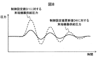
- FIG. 8 is a diagram comparing the end device supply pressure with respect to the control set value D1 and the end device supply pressure with respect to the control set value update value D6.
- the control set value calculation unit 105 corrects the control set value update value D6 so that the deviation amount E of the end device supply pressure calculated value PC with respect to the end device supply pressure set value PS is equal to or less than the threshold value.
- the variation amount of the end device supply pressure with respect to the value D6 is smaller than the variation amount of the end device supply pressure with respect to the control set value D1.
- the electric motor 6 in the control device 4 is reduced so that the fluctuation of the supply pressure to the end device is reduced according to the installation state of the piping layout in accordance with the control setting value update processing procedure shown in FIGS.
- the control set value D1 for controlling the number of rotations is updated. Moreover, the user does not need to input the operating conditions of the air compressor in advance.
- the air compression is performed while suppressing fluctuations in the supply pressure to the end device according to the installation status of the piping layout.
- Compressed air having a desired pressure or higher can be supplied to the terminal device while reducing the power consumption of the machine.
- FIG. 9 is a schematic configuration diagram of the control set value update unit 10 according to the second embodiment.
- the same parts as those in the first embodiment are denoted by the same reference numerals as those in the previous drawings, and the description thereof is omitted.
- the terminal device supply pressure setting value is also updated in the control setting value updating process.
- the pneumatic system operation control apparatus in the present embodiment includes a control set value calculation unit 205 instead of the control set value calculation unit 105.
- control set value calculation unit 205 the control setting value D1, the air piping network model D4, and the end device flow rate D5 are controlled so that the supply pressure value becomes lower while suppressing fluctuations in the supply pressure to the end device.
- the value and the terminal device supply pressure set value are calculated, the supply pressure set value update value PSa is added to the control set value update value D6, and the result is output as the control set value update value D6a.
- FIG. 10 shows a detailed procedure of step S5 (control set value calculation process) according to the second embodiment.
- step S5 control set value calculation process
- processing procedure of the present embodiment is included after step S55 (control setting value correction procedure).
- step S251 supply pressure set value update process
- the control set value calculation unit 205 updates the value so that the end device supply pressure set value PS is minimized within a range where the end device supply pressure is equal to or higher than the required pressure P0.
- the supply pressure set value update value PSa is calculated from the following equation with respect to the minimum value PCmin of the terminal device supply pressure calculation value PC and the required pressure P0.
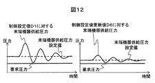
- FIG. 12 is a diagram comparing the end device supply pressure with respect to the control set value D1 and the end device supply pressure with respect to the control set value update value D6a.
- the control set value calculation unit 205 updates the end device supply pressure set value PS so that the supply pressure value becomes low, in addition to the process of suppressing the fluctuation of the supply pressure to the end device.
- the end device supply pressure value for the control set value update value D6a is lower than the end device supply pressure value for the control set value D1.
- the processing procedure of the present embodiment is different from that of the first embodiment, and other points are the same as the processing procedure of the first embodiment.
- the power consumption of the air compressor can be reduced by updating the supply pressure set value so that the supply pressure value becomes low. .
- FIG. 13 is a schematic configuration diagram of the control set value update unit 10 according to the third embodiment.
- the same parts as those in the third embodiment are denoted by the same reference numerals as those in the above drawings, and the description thereof is omitted.
- the terminal device supply pressure fluctuation and the air compressor power consumption value are displayed on the display device with respect to the conditions before and after the control set value update.
- the pneumatic system operation control apparatus includes a control set value calculation unit 305, a control set value storage unit 306, a display instead of the control set value calculation unit 205 and the control set value storage unit 106.
- the unit 301 is provided.
- control set value calculation unit 305 the control setting value D1, the air piping network model D4, and the end device flow rate D5 are controlled so that the supply pressure value becomes lower while suppressing the fluctuation of the supply pressure to the end device.
- the value and the terminal device supply pressure set value are calculated and output as the control set value update value D6a. Further, a piping network flow calculation result D7 for the control set value D1 and the control set value update value D6a is output.
- the control set value storage unit 306 includes a memory and a hard disk, and stores a control set value update value D6a output from the control set value calculation unit 305 and a piping network flow calculation result D7.
- the display unit 301 includes a display device (display). Using the piping network flow calculation result D7, the fluctuation of the terminal device supply pressure with respect to the control set value D1 and the control set value update value D6a, and the power consumption of the air compressor The value is displayed on the display device.
- FIG. 14 illustrates a detailed procedure of the process of step S5 (control set value calculation process) according to the third embodiment.
- the same parts as those in the second embodiment are denoted by the same reference numerals as those in the previous drawings, and the description thereof is omitted.
- processing procedure of the present embodiment differs from the processing procedure of the second embodiment is that the processing procedure of S351 and S352 is included instead of step S56.
- step S351 control set value, pipe flow calculation result storage process
- the control set value calculation unit 305 outputs the control set value update value D6a and the pipe network flow calculation result D7. Stored on hard disk.
- step S352 pressure fluctuation, power consumption display process
- the display unit 301 uses the piping network flow calculation result D7 to change the control pressure value D1 and the fluctuation of the terminal device supply pressure with respect to the control pressure update value D6a, and the air compression.
- the machine power consumption value is displayed on the display device.
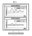
- FIG. 15 shows a display example of the fluctuation of the end device supply pressure and the air compressor power consumption value with respect to the set value D1 and the control set value update value D6a. On the upper side of the display screen, the fluctuation of the end device supply pressure and the air compressor power consumption value with respect to the control set value D1 are displayed.
- the fluctuation of the end device supply pressure and the air compressor power consumption value with respect to the control set value update value D6a are displayed.
- only the fluctuations in the end device supply pressure or only the air compressor power consumption value may be displayed.
- the fluctuation in the end device supply pressure and the air compressor power consumption value are displayed on the display device with respect to the conditions before and after the control set value update.
- the facility administrator of the pneumatic system can confirm the effect of suppressing the pressure fluctuation in the end device and the effect of reducing the power consumption of the air compressor.
- the fluid flowing in the piping network is the air compressor.
- the present invention is not limited to this, and steam, water, air for air conditioning, oil for hydraulic pressure, or the like may flow through the piping network.
Landscapes
- Engineering & Computer Science (AREA)
- Mechanical Engineering (AREA)
- General Engineering & Computer Science (AREA)
- Computer Hardware Design (AREA)
- Control Of Positive-Displacement Pumps (AREA)
- Control Of Fluid Pressure (AREA)
Abstract
空気圧縮機の吐出圧力計測値と、末端機器への供給圧力計測値より、末端機器への供給圧力が一定となるように、空気圧縮機の駆動用電動機の回転数を可変制御する空圧システム運転制御装置であって、吐出圧力計測値と、供給圧力計測値を記憶し、空気配管ネットワーク内の空気流れを計算するためのデータで構成される空気配管ネットワークモデルを入力し、末端機器へ供給される空気流量を計算し、制御設定値の更新値を計算し、更新値に基づき可変制御するための制御設定値を更新する空圧システム運転制御装置を提供する。
Description
本発明は、インバータ等の可変速装置で制御される空気圧縮機を備えた空圧システム運転制御装置および制御方法に関する
近年、地球温暖化防止、省エネ法といった消費電力削減の流れのなかで、工場に対しても消費電力を削減することが求められている。大気中の空気を圧縮した圧縮空気は、身近に利用出来るため、空気工具、空気プレス、空気ブレーキ、スプレーガン等を駆動するための動力源として幅広く用いられている。以降、圧縮空気にて駆動する機器を総称して末端機器と呼ぶ。圧縮空気は空気圧縮機によって圧縮され、工場内に設けられた配管ネットワークを経由して、末端機器に供給される。空気圧縮機の消費電力は、工場全体の消費電力の20~30%を占めるといわれており、工場の省エネルギー化のために空気圧縮機の消費電力を削減する必要がある。
空気圧縮機の消費電力削減のためには、できうるかぎり空気圧縮機の吐出圧力を低減することが望ましい。一方、末端機器を安定に動作させるためには、末端機器に供給する圧縮空気の圧力を所望の圧力以上とする必要がある。空気圧縮機で圧縮した圧縮空気を末端機器に供給する配管ネットワークの圧力損失は、空気圧縮機の吐出空気流量及び末端機器の消費空気流量の変化に応じて変化する。そのため、一般に、末端機器への供給圧力が初望の圧力以上となるように、配管ネットワークの最大圧力損失を見込んで、空気圧縮機の吐出圧力を設定する。これにより、末端機器では所望の圧力以上の圧縮空気を得ることができる。しかし、消費空気流量が少ない場合は、配管ネットワークの圧力損失が小さくなるにもかかわらず、空気圧縮機の吐出圧力が高く設定されたままであるため、必要以上に空気圧縮機を駆動することとなり、余分な電力を消費することとなる。
そこで、これに対応するため、特許文献1では、末端機器への供給圧力と空気圧縮機の吐出圧力を計測し、末端機器での消費空気流量に応じて、末端機器への供給圧力が所望の圧力となるように、空気圧縮機を駆動する電動機の回転数を可変制御することで、空気圧縮機の消費電力を削減しつつ、所望の圧力以上の圧縮空気を末端機器に供給するための空気圧縮機運転制御装置が開示されている。
また、特許文献2では、学習機能により過去の空気圧縮機の運転条件履歴を記憶し、現在の空気圧縮機消費電力、空気圧縮機吐出圧力、および末端機器供給圧力の計測値に対して、過去の運転条件履歴を参照として、空気圧縮機の消費電力を削減しつつ、所望の圧力以上の圧縮空気を末端機器に供給するための空気圧縮機の運転条件を決定する技術が開示されている。
特許文献1で開示されている空気圧縮機運転制御装置により、空気圧縮機の消費電力を削減しつつ、所望の圧力以上の圧縮空気を末端機器に供給することが可能である。一方、配管ネットワークを構成する配管の体積の影響により、空気圧縮機の吐出圧力の変化に対して、末端機器への供給圧力は遅れを伴って変化し、その遅れ時間は数十秒程度となる。空気圧縮機吐出圧力に対して、末端機器供給圧力が遅れて応答するため、一般に、末端機器供給圧力が一定圧力となるように空気圧縮機を制御した場合、末端機器への供給圧力は変動する。そこで、特許文献1で開示されている空気圧縮機運転制御装置では、供給圧力の変動を抑えるように、空気圧縮機を駆動する電動機の回転数をPID制御により制御している。しかしながら、配管の体積は空気圧縮機を設置する配管レイアウトの条件によって異なり、設置後も末端機器の追設等により配管レイアウトは変化する。すなわち、特許文献1で開示されている空気圧縮機運転制御装置では、配管レイアウトの設置状況に応じて、制御設定値を調整することは困難であり、供給圧力が変動する可能性があった。
また、特許文献2で開示されている技術でも、空気圧縮機の消費電力を削減しつつ、所望の圧力以上の圧縮空気を末端機器に供給することが可能である。しかしながら、特許文献2で開示されている技術では、利用者が事前に空気圧縮機の運転条件を入力することが必須であった。また、配管レイアウトが変更された場合には、学習した過去の運転条件履歴を初期化し、再度、利用者が空気圧縮機の運転条件を入力する必要があるという課題があった。
本発明は上記事情に鑑みなされたものであり、利用者が事前に空気圧縮機の運転条件を入力する必要がなく、配管レイアウトの設置状況に応じて、末端機器への供給圧力の変動を抑えながら、空気圧縮機の消費電力を削減しつつ、所望の圧力以上の圧縮空気を末端機器に供給するための空気圧縮機運転制御装置を提供することを目的とする。
上記目的を達成するために、本発明は、
空気圧縮機の吐出圧力計測値と、末端機器への供給圧力計測値より、前記末端機器への供給圧力が一定となるように、前記空気圧縮機の駆動用電動機の回転数を可変制御する空圧システム運転制御装置であって、前記吐出圧力計測値と、前記供給圧力計測値を記憶する計測値記憶部と、前記空気圧縮機から前記末端機器に圧縮空気を供給する経路である空気配管ネットワークを対象として、前記空気配管ネットワーク内の空気流れを計算するためのデータで構成される空気配管ネットワークモデルを入力する空気配管ネットワークモデル入力部と、前記空気配管ネットワークモデルを記憶する空気配管ネットワークモデル記憶部と前記吐出圧力計測値と、前記供給圧力計測値と、前記空気配管ネットワークモデルより、前記末端機器へ供給される空気流量を計算する末端機器流量計算部と、前記空気流量を記憶する末端機器流量記憶部と、前記空気圧縮機の前記駆動用電動機の回転数を可変制御するための制御設定値と、前記空気流量と、前記空気配管ネットワークモデルより、前記制御設定値の更新値を計算する制御設定値計算部と、前記更新値を記憶する制御設定値記憶部と、前記更新値より、前記空気圧縮機の前記駆動用電動機の回転数を可変制御するための制御設定値を更新するための指令値を作成する制御設定値更新指令値作成部とを備えたことを特徴とする。
空気圧縮機の吐出圧力計測値と、末端機器への供給圧力計測値より、前記末端機器への供給圧力が一定となるように、前記空気圧縮機の駆動用電動機の回転数を可変制御する空圧システム運転制御装置であって、前記吐出圧力計測値と、前記供給圧力計測値を記憶する計測値記憶部と、前記空気圧縮機から前記末端機器に圧縮空気を供給する経路である空気配管ネットワークを対象として、前記空気配管ネットワーク内の空気流れを計算するためのデータで構成される空気配管ネットワークモデルを入力する空気配管ネットワークモデル入力部と、前記空気配管ネットワークモデルを記憶する空気配管ネットワークモデル記憶部と前記吐出圧力計測値と、前記供給圧力計測値と、前記空気配管ネットワークモデルより、前記末端機器へ供給される空気流量を計算する末端機器流量計算部と、前記空気流量を記憶する末端機器流量記憶部と、前記空気圧縮機の前記駆動用電動機の回転数を可変制御するための制御設定値と、前記空気流量と、前記空気配管ネットワークモデルより、前記制御設定値の更新値を計算する制御設定値計算部と、前記更新値を記憶する制御設定値記憶部と、前記更新値より、前記空気圧縮機の前記駆動用電動機の回転数を可変制御するための制御設定値を更新するための指令値を作成する制御設定値更新指令値作成部とを備えたことを特徴とする。
本発明によれば、利用者が事前に空気圧縮機の運転条件を入力する必要がなく、配管レイアウトの設置状況に応じて、末端機器への供給圧力の変動を抑えながら、空気圧縮機の消費電力を削減しつつ、所望の圧力以上の圧縮空気を末端機器に供給できる。
以下に図面を用いて本発明の実施の形態を説明する。
図1は実施例1に係る空圧システム運転制御装置の概略構成図である。
図1に示した空圧システム運転制御装置は、空気圧縮機ユニット1、空気配管ネットワーク7、末端機器8、末端機器部圧力センサー9、制御設定値更新部10を備えている。
空気圧縮機ユニット1は、大気から吸込んだ空気Aを圧縮し圧縮空気を吐出する。空気圧縮機ユニット1は、空気圧縮機本体2、空気圧縮機吐出部圧力センサー3、制御装置4、可変速装置5、電動機6から構成される。以下では、空気圧縮機ユニット1の概略構成について説明する。
空気圧縮機本体2は、空気Aを吸込んで圧縮する。
空気圧縮機吐出部圧力センサー3は、空気圧縮機本体2から吐出する圧縮機空気の圧力を計測する。計測された圧力値は、制御装置4および制御設定値更新部10に出力される。
制御装置4は、空気圧縮機吐出部圧力センサー3の圧力計測値、末端機器部圧力センサー9の圧力計測値を入力として、末端機器8への圧縮機空気の供給圧力が要求圧力P0以上となるように、電動機6の回転数を制御し、電動機6に対する回転数指令値を計算、出力する。電動機6の回転数を制御する具体的な演算方法については、例えば、特許文献1「特開2010-24845号公報」に記載された方法により実現可能である。また、制御装置4は、電動機6の回転数を制御するための制御設定値D1の現在値を制御設定値更新部10に出力するとともに、制御設定値更新部10が出力する制御設定値更新指令値D2に基づき、制御設定値の現在値D1を更新する。
可変速装置5は、回転数指令値を入力として電動機6を指定した回転数で回転させるために必要となる電力を出力する。
電動機6は空気圧縮機本体2と回転軸を介して結合しており、入力された電力をもとに回転し、空気圧縮機本体2を駆動させる。
以上が空気圧縮機ユニット1の概略構成である。
空気配管ネットワーク7は、空気層、フィルタ、ドライヤー、配管、エルボ、分岐、弁等の機器から構成され、空気圧縮機ユニット1から吐出した圧縮空気は空気配管ネットワーク7を介して、末端機器8に供給される。
末端機器8は、空気工具、空気プレス、空気ブレーキ、スプレーガン等、工場の製造工程で使用される機器であり、空気配管ネットワーク7を介して供給される圧縮空気を動力源として駆動する。
末端機器部圧力センサー9は、末端機器8に供給される圧縮機空気の圧力を計測する。計測された圧力値は、制御装置4および制御設定値更新部10に出力される。
制御設定値更新部10は、空気圧縮機吐出部圧力センサー3の圧力計測値、末端機器部圧力センサー9の圧力計測値を入力として、制御設定値更新指令値を出力する。制御装置4は、上記の制御設定値更新指令値を入力として、制御設定値を更新する。
以下では、図2を用いて制御設定値更新部10の詳細について説明する。制御設定値更新部10は、計測値記憶部100、空気配管ネットワークモデル入力部101、空気配管ネットワークモデル記憶部102、末端機器流量計算部103、末端機器流量記憶部104、制御設定値計算部105、制御設定値記憶部106、制御設定値更新指令値作成部107から構成される。
計測値記憶部100は、メモリやハードディスクで構成されており、空気圧縮機吐出部圧力センサー3および末端機器部圧力センサー9で取得した圧力計測値D3を格納する。
空気配管ネットワークモデル入力部101では、空気配管ネットワーク7内の圧縮空気の流れを計算するために必要となるデータを入力し、空気配管ネットワークモデルD4を出力する。具体的には、空気配管ネットワーク7を構成する機器間の接続関係を定義するデータ、機器の属性(例えば、配管に対しては配管長さ、配管口径等)を定義するデータ、および空気圧縮機ユニット1の吐出空気圧力を計算するためのデータである。
空気配管ネットワークモデル記憶部102は、メモリやハードディスクで構成されており、空気配管ネットワークモデル入力部101が出力する空気配管ネットワークモデルD4を格納する。
末端機器流量計算部103では、圧力計測値D3、空気配管ネットワークモデルD4より、空気配管ネットワーク7内の空気流れを計算し、末端機器に供給される圧縮空気流量である末端機器流量D5を出力する。空気配管ネットワーク7内の空気流れを計算する具体的な計算手法については、例えば、文献「G.P. Greyvenstein(2002), An implicit method for the analysis of transient flows in pipe networks, International Journa
l for Numerical Methods in Engineering, vol. 53, issue 5, pp. 1127-1143」に記載された手法により実現可能である。
l for Numerical Methods in Engineering, vol. 53, issue 5, pp. 1127-1143」に記載された手法により実現可能である。
末端機器流量記憶部104は、メモリやハードディスクで構成されており末端機器流量計算部103が出力する末端機器流量D5を格納する。
制御設定値計算部105では、制御設定値D1、空気配管ネットワークモデルD4、末端機器流量D5より、末端機器への供給圧力の変動を抑制するように、制御設定値を計算し、制御設定値更新値D6として出力する。制御設定値更新値D6の具体的な計算方法については、図6、図7、図8を用いて後述する。
制御設定値記憶部106は、メモリやハードディスクで構成されており制御設定値計算部105が出力する制御設定値更新値D6を格納する。
制御設定値更新指令値作成部107は、制御設定値更新値D6を入力として、制御装置4の制御設定値D1を更新するための制御設定値更新指令値D2を出力する。
以上が、空圧システム運転制御装置の構成である。次に、制御設定値更新部10の処理の内容を詳細に説明する。図3は、実施例1に係る空圧システム運転制御装置における制御設定値更新の処理手順を示す。
ステップS1(計測値取得過程)として、計測値記憶部100は、空気圧縮機吐出部圧力センサー3および末端機器部圧力センサー9で取得した圧力計測値D3をメモリやハードディスクに格納する。
ステップS2(制御設定値タイミング判定過程)として、制御設定値更新部10は、現在時刻が、あらかじめ設定されている制御設定値更新タイミングと一致しているか否かを判定する。判定結果がYesならば、ステップS3(配管ネットワークモデル生成過程)に進み、Noならば、ステップS1の処理を継続する。ステップS1、S2の処理により、図4に示す、空気圧縮機吐出部の圧縮空気圧力、および末端機器8に供給される圧縮空気圧力の時系列データが得られる。
ステップS3(配管ネットワークモデル生成過程)として、空気配管ネットワークモデル入力部101は、空気配管ネットワーク7内の圧縮空気の流れを計算するために必要となるデータを入力し、空気配管ネットワークモデルD4を出力する。空気配管ネットワークモデルD4は、空気配管ネットワークモデル記憶部102によりメモリやハードディスクに格納される。
ステップS4(末端機器流量計算過程)として、末端機器流量計算部103は、圧力計測値D3、空気配管ネットワークモデルD4より、空気配管ネットワーク7内の空気流れを計算し、末端機器に供給される圧縮空気流量である末端機器流量D5を出力する。図5は、図4に示す、空気圧縮機吐出部の圧縮空気圧力、および末端機器8に供給される圧縮空気圧力の時系列データに対して、末端機器流量計算部103により出力される末端機器流量D5の例である。末端機器流量D5は、末端機器流量記憶部104によりメモリやハードディスクに格納される。
ステップS5(制御設定値計算過程)として、制御設定値計算部105は、制御設定値D1、空気配管ネットワークモデルD4、末端機器流量D5より、末端機器への供給圧力の変動を抑制するように、制御設定値更新値D6を計算する。ステップS5の処理の詳細については、図6、図7、図8を用いて後述する。制御設定値更新値D6は、制御設定値記憶部106によりメモリやハードディスクに格納される。
ステップS6(制御設定値更新指令値出力過程)として、制御設定値更新指令値作成部107は、制御設定値更新値D6を入力として、制御装置4の制御設定値D1を更新するための制御設定値更新指令値D2を出力する。
次に、ステップS5(制御設定値計算過程)の処理の詳細について、図6、図7、図8を用いて説明する。図6に示すように、ステップS5はステップS51~ステップS56の6つの処理過程を含む。
ステップS51(制御設定値初期化過程)として、制御設定値計算部105は、制御設定値D1を制御設定値更新値D6に代入し、初期化する。例えば、制御装置4がPID制御により電動機6の回転数を制御する場合は、制御設定値D1は、比例ゲインKP、積分時間TI,微分時間TDの3つのパラメータとなり、制御設定値更新値D6にはこれら3つのパラメータの現在値が代入される。
ステップS52(配管ネットワーク空気流れ計算過程)として、制御設定値計算部105は、空気配管ネットワークモデルD4、末端機器流量D5、制御設定値更新値D6より、空気配管ネットワーク7内の空気流れを計算し、末端機器8に供給される圧縮空気圧力である末端器供給圧力計算値PCを出力する。
ステップS53(圧力偏差量計算過程)として、制御設定値計算部105は、末端機器8への供給圧力の変動量を評価する指標として、末端機器供給圧力設定値PSに対する末端器供給圧力計算値PCの偏差量Eを計算する。ここで、偏差量Eは、図7に示す図中の斜線で示す面積値であり、以下の式より計算される。
E=∫|PC-PS|dt・・・(式1)
また、末端機器供給圧力設定値PSに関しては、制御装置4における電動機6の回転数の制御により、末端機器供給圧力が要求圧力P0以上となるように、その値が設定される。空気配管ネットワーク7を構成する配管の体積の影響により、空気圧縮機吐出圧力に対して、末端機器供給圧力が遅れて応答する。そのため、末端機器供給圧力が一定圧力となるように空気圧縮機を制御した場合、末端機器供給圧力は変動する。そのため、図7に示すように、末端機器供給圧力設定値PSは要求圧力P0よりも高く設定される。
また、末端機器供給圧力設定値PSに関しては、制御装置4における電動機6の回転数の制御により、末端機器供給圧力が要求圧力P0以上となるように、その値が設定される。空気配管ネットワーク7を構成する配管の体積の影響により、空気圧縮機吐出圧力に対して、末端機器供給圧力が遅れて応答する。そのため、末端機器供給圧力が一定圧力となるように空気圧縮機を制御した場合、末端機器供給圧力は変動する。そのため、図7に示すように、末端機器供給圧力設定値PSは要求圧力P0よりも高く設定される。
ステップS54(制御設定値更新処理終了判定過程)として、制御設定値計算部105は、偏差量Eが閾値より大きいか否かを判定する。判定結果がYesならばステップS56(制御設定値格納過程)に進み、Noの場合は、ステップS55(制御設定値修正過程)へ進む。
ステップS55(制御設定値修正過程)として、制御設定値計算部105は、偏差量Eが減少するように、制御設定値更新値D6を修正する。制御設定値更新値D6を修正する具体的な計算方法としては、例えば、公知の最適化アルゴリズムである遺伝的アルゴリズム法、焼きなまし法等の手法により実現可能である。
ステップS56(制御設定値格納過程)として、制御設定値計算部105は、制御設定値更新値D6を出力し、制御設定値記憶部106によりメモリやハードディスクに格納される。
図8は、制御設定値D1に対する末端機器供給圧力と、制御設定値更新値D6に対する末端機器供給圧力を比較した図である。制御設定値計算部105は、末端機器供給圧力設定値PSに対する末端器供給圧力計算値PCの偏差量Eが閾値以下となるように、制御設定値更新値D6を修正するため、制御設定値更新値D6に対する末端機器供給圧力の変動量は、制御設定値D1に対する末端機器供給圧力の変動量よりも小さい結果となる。
以上が、ステップS5の処理の詳細に関する説明である。
実施例では、図3、図6に示した制御設定値更新の処理手順に従って、配管レイアウトの設置状況に応じて、末端機器への供給圧力の変動が小さくなるように、制御装置4における電動機6の回転数を制御するための制御設定値D1が更新される。また、利用者は、事前に空気圧縮機の運転条件を入力する必要はない。
上述の通り、本実施形態では、利用者が事前に空気圧縮機の運転条件を入力する必要がなく、配管レイアウトの設置状況に応じて、末端機器への供給圧力の変動を抑えながら、空気圧縮機の消費電力を削減しつつ、所望の圧力以上の圧縮空気を末端機器に供給できる。
図9は実施例2に係る制御設定値更新部10の概略構成図である。実施例1と同様の部分については同図において既出図面と同符号を付して説明を省略する。
実施例1と相違する点は、制御設定値の更新処理において、末端機器供給圧力設定値も更新する点である。具体的には、本実施例における空圧システム運転制御装置は、制御設定値計算部105の代わりに、制御設定値計算部205を備える。
制御設定値計算部205では、制御設定値D1、空気配管ネットワークモデルD4、末端機器流量D5より、末端機器への供給圧力の変動を抑制しつつ、その供給圧力値が低くなるように、制御設定値と末端機器供給圧力設定値を計算し、制御設定値更新値D6に供給圧力設定値更新値PSaを加えて、制御設定値更新値D6aとして出力する。
以上が、実施例1と相違する点であり、その他の点は実施例1と同様である。
次に、制御設定値更新部10の処理の内容を詳細に説明する。図10は、実施例2に係るステップS5(制御設定値計算過程)の処理の詳細手順を示す。実施例1と同様の部分については同図において既出図面と同符号を付して説明を省略する。
本実施例の処理手順が実施例1の処理手順と相違する点は、ステップS55(制御設定値修正過程)の後に、S251の処理過程を含む点である。
ステップS251(供給圧力設定値更新過程)として、制御設定値計算部205は、末端機器供給圧力が要求圧力P0以上となる範囲内で、末端機器供給圧力設定値PSが最小となるよう値を更新する。具体的は、図11に示すように、末端器供給圧力計算値PCの最小値PCmin、要求圧力P0に対して、供給圧力設定値更新値PSaは、以下の式より計算される。
PSa=PS-(PCmin-P0)・・・(式2)
図12は、制御設定値D1に対する末端機器供給圧力と、制御設定値更新値D6aに対する末端機器供給圧力を比較した図である。制御設定値計算部205は、末端機器への供給圧力の変動を抑制する処理に加え、その供給圧力値が低くなるように末端機器供給圧力設定値PSを更新する。これにより、制御設定値更新値D6aに対する末端機器供給圧力値は、制御設定値D1に対する末端機器供給圧力値よりも低い値となる。末端機器供給圧力が低くなることにより、空気圧縮機の吐出圧力も低くすることができ、空気圧縮機の消費電力を削減することが可能である。
図12は、制御設定値D1に対する末端機器供給圧力と、制御設定値更新値D6aに対する末端機器供給圧力を比較した図である。制御設定値計算部205は、末端機器への供給圧力の変動を抑制する処理に加え、その供給圧力値が低くなるように末端機器供給圧力設定値PSを更新する。これにより、制御設定値更新値D6aに対する末端機器供給圧力値は、制御設定値D1に対する末端機器供給圧力値よりも低い値となる。末端機器供給圧力が低くなることにより、空気圧縮機の吐出圧力も低くすることができ、空気圧縮機の消費電力を削減することが可能である。
以上が、本実施例の処理手順が実施例1と相違する点であり、その他の点は実施例1の処理手順と同様である。
上述の通り、本実施例では実施例1で得られる各効果に加えて、供給圧力値が低くなるように供給圧力設定値を更新することで、空気圧縮機の消費電力を削減することができる。
図13は実施例3に係る制御設定値更新部10の概略構成図である。実施例3と同様の部分については同図において既出図面と同符号を付して説明を省略する。
実施例2と相違する点は、制御設定値更新前と更新後の条件に対して、末端機器供給圧力の変動、および空気圧縮機消費電力値を表示装置に表示する点である。具体的には、本実施の形態における空圧システム運転制御装置は、制御設定値計算部205、制御設定値記憶部106の代わりに、制御設定値計算部305、制御設定値記憶部306、表示部301を備える。
制御設定値計算部305では、制御設定値D1、空気配管ネットワークモデルD4、末端機器流量D5より、末端機器への供給圧力の変動を抑制しつつ、その供給圧力値が低くなるように、制御設定値と末端機器供給圧力設定値を計算し、制御設定値更新値D6aとして出力する。さらに、制御設定値D1と制御設定値更新値D6aに対する配管ネットワーク流れ計算結果D7を出力する。
制御設定値記憶部306は、メモリやハードディスクで構成されており制御設定値計算部305が出力する制御設定値更新値D6aと配管ネットワーク流れ計算結果D7を格納する。
表示部301は、表示装置(ディスプレイ)を備えており、配管ネットワーク流れ計算結果D7を用いて、制御設定値D1と制御設定値更新値D6aに対する末端機器供給圧力の変動、および空気圧縮機消費電力値を表示装置に表示する。
以上が、実施例2と相違する点であり、その他の点は実施例2と同様である。
次に、制御設定値更新部10の処理の内容を詳細に説明する。図14は、実施例3に係るステップS5(制御設定値計算過程)の処理の詳細手順を示す。実施例2と同様の部分については同図において既出図面と同符号を付して説明を省略する。
本実施の形態の処理手順が実施例2の処理手順と相違する点は、ステップS56の代わりに、S351、S352の処理過程を含む点である。
ステップS351(制御設定値、配管流れ計算結果格納過程)として、制御設定値計算部305は、制御設定値更新値D6aと配管ネットワーク流れ計算結果D7を出力し、制御設定値記憶部306によりメモリやハードディスクに格納される。
ステップS352(圧力変動、消費電力表示過程)として、表示部301は、配管ネットワーク流れ計算結果D7を用いて、制御設定値D1と制御設定値更新値D6aに対する末端機器供給圧力の変動、および空気圧縮機消費電力値を表示装置に表示する。図15は、設定値D1と制御設定値更新値D6aに対する末端機器供給圧力の変動、および空気圧縮機消費電力値の表示例を示している。表示画面上側には、制御設定値D1に対する末端機器供給圧力の変動と空気圧縮機消費電力値が表示されている。表示画面下側には、制御設定値更新値D6aに対する末端機器供給圧力の変動と空気圧縮機消費電力値が表示されている。図15に示した表示例の他に、末端機器供給圧力の変動のみ、あるいは空気圧縮機消費電力値のみが表示されていてもよい。
以上が、本実施例の処理手順が実施例2と相違する点であり、その他の点は実施例2の処理手順と同様である。
上述の通り、実施例2で得られる各効果に加えて、制御設定値更新前と更新後の条件に対して、末端機器供給圧力の変動、および空気圧縮機消費電力値を表示装置に表示することで、空圧システムの設備管理者が末端機器における圧力変動の抑制効果、空気圧縮機の消費電力削減効果を確認できる
本発明における上記実施例では、配管ネットワーク内に流れる流体が、空気圧縮機により圧縮された圧縮空気である形態について説明したが、本発明はこれに限定されるものではなく、配管ネットワーク内を蒸気、水、空調用空気、油圧用の油等が流れる形態としてよい。
本発明における上記実施例では、配管ネットワーク内に流れる流体が、空気圧縮機により圧縮された圧縮空気である形態について説明したが、本発明はこれに限定されるものではなく、配管ネットワーク内を蒸気、水、空調用空気、油圧用の油等が流れる形態としてよい。
1 空気圧縮機ユニット
2 空気圧縮機本体
3 空気圧縮機吐出部圧力センサー
4 制御装置
5 可変速装置
6 電動機
7 空気配管ネットワーク
8 末端機器
9 末端機器部圧力センサー
10 制御設定値更新部
100 計測値記憶部
101 空気配管ネットワークモデル入力部
102 空気配管ネットワークモデル記憶部
103 末端機器流量計算部
104 末端機器流量記憶部
105、205、305 制御設定値計算部
106、306 制御設定値記憶部
107 制御設定値更新指令値作成部
301 表示部
2 空気圧縮機本体
3 空気圧縮機吐出部圧力センサー
4 制御装置
5 可変速装置
6 電動機
7 空気配管ネットワーク
8 末端機器
9 末端機器部圧力センサー
10 制御設定値更新部
100 計測値記憶部
101 空気配管ネットワークモデル入力部
102 空気配管ネットワークモデル記憶部
103 末端機器流量計算部
104 末端機器流量記憶部
105、205、305 制御設定値計算部
106、306 制御設定値記憶部
107 制御設定値更新指令値作成部
301 表示部
Claims (6)
- 空気圧縮機の吐出圧力計測値と、末端機器への供給圧力計測値より、前記末端機器への供給圧力が一定となるように、前記空気圧縮機の駆動用電動機の回転数を可変制御する空圧システム運転制御装置であって、
前記吐出圧力計測値と、前記供給圧力計測値を記憶する計測値記憶部と、
前記空気圧縮機から前記末端機器に圧縮空気を供給する経路である空気配管ネットワークを対象として、前記空気配管ネットワーク内の空気流れを計算するためのデータで構成される空気配管ネットワークモデルを入力する空気配管ネットワークモデル入力部と、
前記空気配管ネットワークモデルを記憶する空気配管ネットワークモデル記憶部と
前記吐出圧力計測値と、前記供給圧力計測値と、前記空気配管ネットワークモデルより、前記末端機器へ供給される空気流量を計算する末端機器流量計算部と、
前記空気流量を記憶する末端機器流量記憶部と、
前記空気圧縮機の前記駆動用電動機の回転数を可変制御するための制御設定値と、前記空気流量と、前記空気配管ネットワークモデルより、前記制御設定値の更新値を計算する制御設定値計算部と、
前記更新値を記憶する制御設定値記憶部と、
前記更新値より、前記空気圧縮機の前記駆動用電動機の回転数を可変制御するための制御設定値を更新するための指令値を作成する制御設定値更新指令値作成部と
を備えたことを特徴とする空圧システム運転制御装置。 - 請求項1に記載の空圧システム運転制御装置において、
前記制御設定値計算部は、前記制御設定値の更新値と、前記末端機器への供給圧力設定値の更新値とを計算することを特徴とする空圧システム運転制御装置 - 請求項1又は請求項2にのいずれか1項に記載の空圧システム運転制御装置において、
前記制御設定値計算部は、前記制御装置更新前と更新後の条件に対する、前記空気配管ネットワークの内の空気流れ計算結果を出力し、
前記制御設定値記憶部は、前記空気流れ計算結果を記憶し、
前記空気流れ計算結果より、前記制御装置更新前と更新後の条件に対する、前記末端機器での圧力変動、あるいは前記空気圧縮機の消費電力を表示する表示部と
を備えたことを特徴とする空圧システム運転制御装置。 - 空気圧縮機の吐出圧力計測値と、末端機器への供給圧力計測値より、前記末端機器への供給圧力が一定となるように、前記空気圧縮機の駆動用電動機の回転数を可変制御する空圧システム運転制御方法であって、
前記吐出圧力計測値と、前記供給圧力計測値を記憶し、
前記空気圧縮機から前記末端機器に圧縮空気を供給する経路である空気配管ネットワークを対象として、前記空気配管ネットワーク内の空気流れを計算するためのデータで構成される空気配管ネットワークモデルを入力し、
前記空気配管ネットワークモデルを記憶し、
前記吐出圧力計測値と、前記供給圧力計測値と、前記空気配管ネットワークモデルより、前記末端機器へ供給される空気流量を計算し、
前記空気流量を記憶し、
前記空気圧縮機の前記駆動用電動機の回転数を可変制御するための制御設定値と、前記空気流量と、前記空気配管ネットワークモデルより、前記制御設定値の更新値を計算し、
前記更新値を記憶し、
前記更新値より、前記空気圧縮機の前記駆動用電動機の回転数を可変制御するための制御設定値を更新する
ことを特徴とする空圧システム運転制御方法。 - 請求項4に記載の空圧システム運転制御方法において、
前記制御設定値の更新値の計算は、前記制御設定値の更新値と、前記末端機器への供給圧力設定値の更新値とを計算することを特徴とする空圧システム運転制御方法 - 請求項1又は請求項2のいずれか1項に記載の空圧システム運転制御方法において、
前記制御設定値の更新値の計算は、前記制御装置更新前と更新後の条件に対する、前記空気配管ネットワークの内の空気流れ計算結果を出力し、
前記更新値の記憶は、前記空気流れ計算結果を記憶し、
前記空気流れ計算結果より、前記制御装置更新前と更新後の条件に対する、前記末端機器での圧力変動、あるいは前記空気圧縮機の消費電力を表示する
ことを特徴とする空圧システム運転制御方法。
Priority Applications (3)
| Application Number | Priority Date | Filing Date | Title |
|---|---|---|---|
| US16/064,868 US10550837B2 (en) | 2015-12-25 | 2016-07-15 | Pneumatic system operation control device and control method |
| EP16878023.7A EP3396160B1 (en) | 2015-12-25 | 2016-07-15 | Pneumatic system operation control device and control method |
| CN201680058840.0A CN108138761B (zh) | 2015-12-25 | 2016-07-15 | 气动系统运行控制装置和控制方法 |
Applications Claiming Priority (2)
| Application Number | Priority Date | Filing Date | Title |
|---|---|---|---|
| JP2015252808A JP6704247B2 (ja) | 2015-12-25 | 2015-12-25 | 空圧システム運転制御装置および制御方法 |
| JP2015-252808 | 2015-12-25 |
Publications (1)
| Publication Number | Publication Date |
|---|---|
| WO2017110120A1 true WO2017110120A1 (ja) | 2017-06-29 |
Family
ID=59089979
Family Applications (1)
| Application Number | Title | Priority Date | Filing Date |
|---|---|---|---|
| PCT/JP2016/070926 Ceased WO2017110120A1 (ja) | 2015-12-25 | 2016-07-15 | 空圧システム運転制御装置および制御方法 |
Country Status (5)
| Country | Link |
|---|---|
| US (1) | US10550837B2 (ja) |
| EP (1) | EP3396160B1 (ja) |
| JP (1) | JP6704247B2 (ja) |
| CN (1) | CN108138761B (ja) |
| WO (1) | WO2017110120A1 (ja) |
Families Citing this family (8)
| Publication number | Priority date | Publication date | Assignee | Title |
|---|---|---|---|---|
| JP6986979B2 (ja) | 2018-01-17 | 2021-12-22 | 株式会社日立産機システム | 空圧システムのリアルタイム制御装置および方法 |
| JP7326847B2 (ja) * | 2019-04-25 | 2023-08-16 | マックス株式会社 | 空気圧縮機 |
| CN111038423B (zh) * | 2019-12-04 | 2021-06-04 | 珠海格力电器股份有限公司 | 一种气动控制方法、装置、计算机可读存储介质及车辆 |
| JP7291637B2 (ja) * | 2020-01-06 | 2023-06-15 | 株式会社日立産機システム | 圧縮機制御装置の設定値決定支援装置及び設定値決定支援方法、並びに圧縮機運転制御システム |
| WO2021161133A1 (en) * | 2020-02-10 | 2021-08-19 | Khalifa University of Science and Technology | An apparatus for optimal loadsharing between parallel gas compressors |
| JP7432740B2 (ja) * | 2020-08-24 | 2024-02-16 | 株式会社日立産機システム | 空気圧縮機 |
| KR102393531B1 (ko) * | 2020-09-18 | 2022-05-03 | (주)제아이엔지 | 성능 유지 및 자가 진단 가능한 고압 압축기 |
| BE1030263B1 (nl) * | 2022-02-09 | 2023-09-11 | Atlas Copco Airpower Nv | Optimalisering of verhoging van de efficiëntie van een systeem voor op druk gebracht fluïdum dat een netwerk van drukleidingen omvat dat dynamisch belast wordt |
Citations (3)
| Publication number | Priority date | Publication date | Assignee | Title |
|---|---|---|---|---|
| JP2007291870A (ja) | 2006-04-21 | 2007-11-08 | Chugoku Electric Power Co Inc:The | コンプレッサ運用診断アシストシステム |
| JP2010024845A (ja) | 2008-07-15 | 2010-02-04 | Hitachi Industrial Equipment Systems Co Ltd | 圧縮空気製造設備 |
| JP2011038479A (ja) * | 2009-08-12 | 2011-02-24 | Seiko Epson Corp | 流体噴射装置、流体噴射装置の制御方法 |
Family Cites Families (8)
| Publication number | Priority date | Publication date | Assignee | Title |
|---|---|---|---|---|
| JPH06173878A (ja) * | 1992-12-03 | 1994-06-21 | Hitachi Ltd | 可変容量形圧縮機 |
| DE10000669C2 (de) * | 2000-01-11 | 2002-02-28 | Airbus Gmbh | Luftmassenstromregelsystem mit Druckhöhenkorrektur für ein Verkehrsflugzeug |
| JP4482416B2 (ja) * | 2004-09-30 | 2010-06-16 | 株式会社神戸製鋼所 | 圧縮機 |
| JP4786443B2 (ja) | 2006-07-11 | 2011-10-05 | 株式会社日立産機システム | 圧縮空気製造設備 |
| DE102008064491A1 (de) * | 2008-12-23 | 2010-06-24 | Kaeser Kompressoren Gmbh | Simulationsgestütztes Verfahren zur Steuerung bzw. Regelung von Druckluftstationen |
| JP2011185190A (ja) * | 2010-03-10 | 2011-09-22 | Ebara Corp | 制御装置一体型モータポンプ |
| DE102011012558B3 (de) * | 2011-02-26 | 2012-07-12 | Festo Ag & Co. Kg | Druckluft-Wartungsgerät und damit ausgestattete Verbrauchersteuervorrichtung |
| US11231037B2 (en) * | 2013-03-22 | 2022-01-25 | Kaeser Kompressoren Se | Measured value standardization |
-
2015
- 2015-12-25 JP JP2015252808A patent/JP6704247B2/ja active Active
-
2016
- 2016-07-15 US US16/064,868 patent/US10550837B2/en active Active
- 2016-07-15 EP EP16878023.7A patent/EP3396160B1/en active Active
- 2016-07-15 WO PCT/JP2016/070926 patent/WO2017110120A1/ja not_active Ceased
- 2016-07-15 CN CN201680058840.0A patent/CN108138761B/zh active Active
Patent Citations (3)
| Publication number | Priority date | Publication date | Assignee | Title |
|---|---|---|---|---|
| JP2007291870A (ja) | 2006-04-21 | 2007-11-08 | Chugoku Electric Power Co Inc:The | コンプレッサ運用診断アシストシステム |
| JP2010024845A (ja) | 2008-07-15 | 2010-02-04 | Hitachi Industrial Equipment Systems Co Ltd | 圧縮空気製造設備 |
| JP2011038479A (ja) * | 2009-08-12 | 2011-02-24 | Seiko Epson Corp | 流体噴射装置、流体噴射装置の制御方法 |
Non-Patent Citations (2)
| Title |
|---|
| G.P. GREYVENSTEIN: "An implicit method for the analysis of transient flows in pipe networks", INTERNATIONAL JOURNAL FOR NUMERICAL METHODS IN ENGINEERING, vol. 53, no. 5, 2002, pages 1127 - 1143 |
| See also references of EP3396160A4 |
Also Published As
| Publication number | Publication date |
|---|---|
| US10550837B2 (en) | 2020-02-04 |
| US20180372086A1 (en) | 2018-12-27 |
| EP3396160A1 (en) | 2018-10-31 |
| EP3396160B1 (en) | 2021-05-05 |
| CN108138761B (zh) | 2020-01-03 |
| EP3396160A4 (en) | 2019-08-14 |
| CN108138761A (zh) | 2018-06-08 |
| JP2017115730A (ja) | 2017-06-29 |
| JP6704247B2 (ja) | 2020-06-03 |
Similar Documents
| Publication | Publication Date | Title |
|---|---|---|
| JP6704247B2 (ja) | 空圧システム運転制御装置および制御方法 | |
| JP6166482B2 (ja) | 圧縮機制御装置、圧縮機制御システム及び圧縮機制御方法 | |
| US20070212230A1 (en) | Method for optimizing valve position and pump speed in a PID control valve system without the use of external signals | |
| KR102177193B1 (ko) | 오일 주입식 압축기 또는 진공 펌프의 출구 온도를 제어하기 위한 방법 및 이러한 방법을 구현하는 오일 주입식 압축기 또는 진공 펌프 | |
| JP6986979B2 (ja) | 空圧システムのリアルタイム制御装置および方法 | |
| CN105201807B (zh) | 一种基于压力差和流量控制的压缩机运行控制方法和装置 | |
| CN110107525B (zh) | 一种离心式空压站系统压力的控制方法 | |
| JP3217612U (ja) | 圧縮器の速度を供給源から出ている利用可能なガスの流れの関数として制御するためのコントローラ及びそのようなコントローラを含む圧縮器 | |
| JP6773530B2 (ja) | 末端圧力制御装置および末端圧力制御方法 | |
| JP4938304B2 (ja) | ポンプの制御方法及び給水装置 | |
| KR100644751B1 (ko) | 압축공기 공급압력 능동서보제어 시스템 | |
| JP5982702B2 (ja) | ボイラの給水制御方法および給水制御装置 | |
| CN114625184A (zh) | 一种半导体设备的压力控制系统 | |
| JP6746714B2 (ja) | 流体供給設備及びその制御方法 | |
| CN110168453B (zh) | 用于冷水crac单元自适应pid控制 | |
| JP2005194970A (ja) | ポンプの吐出圧力制御方法及び装置 | |
| CN114562452B (zh) | 用于控制工业设备的方法、系统、设备和介质 | |
| TW201423296A (zh) | 系統控制裝置及其控制方法、程式以及控制系統 | |
| JP2020143641A (ja) | 圧縮機の圧力制御方法および圧力制御装置 | |
| WO2017159279A1 (ja) | 圧縮機 | |
| KR20170127627A (ko) | 공기압축기의 통합 제어 장치 | |
| CN106021936A (zh) | 机组调速器压油槽快速建压方法 | |
| CN118591810A (zh) | 用于提高包括加压管道网络的加压流体系统在动态负载下的效率和/或增加其操作范围的方法 | |
| JP2007239696A (ja) | 圧縮機の制御装置、圧縮機装置及び圧縮機装置の制御方法 | |
| JP2016075152A (ja) | 圧縮機設備、これを備えるガスタービンプラント、及び圧縮機設備の制御方法 |
Legal Events
| Date | Code | Title | Description |
|---|---|---|---|
| 121 | Ep: the epo has been informed by wipo that ep was designated in this application |
Ref document number: 16878023 Country of ref document: EP Kind code of ref document: A1 |
|
| NENP | Non-entry into the national phase |
Ref country code: DE |