WO2017110581A1 - 粒子状物質の測定装置用部品 - Google Patents
粒子状物質の測定装置用部品 Download PDFInfo
- Publication number
- WO2017110581A1 WO2017110581A1 PCT/JP2016/087048 JP2016087048W WO2017110581A1 WO 2017110581 A1 WO2017110581 A1 WO 2017110581A1 JP 2016087048 W JP2016087048 W JP 2016087048W WO 2017110581 A1 WO2017110581 A1 WO 2017110581A1
- Authority
- WO
- WIPO (PCT)
- Prior art keywords
- filter
- particulate matter
- base
- flow path
- measuring device
- Prior art date
- Legal status (The legal status is an assumption and is not a legal conclusion. Google has not performed a legal analysis and makes no representation as to the accuracy of the status listed.)
- Ceased
Links
Images









Classifications
-
- G—PHYSICS
- G01—MEASURING; TESTING
- G01N—INVESTIGATING OR ANALYSING MATERIALS BY DETERMINING THEIR CHEMICAL OR PHYSICAL PROPERTIES
- G01N27/00—Investigating or analysing materials by the use of electric, electrochemical, or magnetic means
- G01N27/02—Investigating or analysing materials by the use of electric, electrochemical, or magnetic means by investigating impedance
- G01N27/22—Investigating or analysing materials by the use of electric, electrochemical, or magnetic means by investigating impedance by investigating capacitance
-
- F—MECHANICAL ENGINEERING; LIGHTING; HEATING; WEAPONS; BLASTING
- F01—MACHINES OR ENGINES IN GENERAL; ENGINE PLANTS IN GENERAL; STEAM ENGINES
- F01N—GAS-FLOW SILENCERS OR EXHAUST APPARATUS FOR MACHINES OR ENGINES IN GENERAL; GAS-FLOW SILENCERS OR EXHAUST APPARATUS FOR INTERNAL-COMBUSTION ENGINES
- F01N11/00—Monitoring or diagnostic devices for exhaust-gas treatment apparatus
-
- G—PHYSICS
- G01—MEASURING; TESTING
- G01N—INVESTIGATING OR ANALYSING MATERIALS BY DETERMINING THEIR CHEMICAL OR PHYSICAL PROPERTIES
- G01N15/00—Investigating characteristics of particles; Investigating permeability, pore-volume or surface-area of porous materials
- G01N15/06—Investigating concentration of particle suspensions
- G01N15/0656—Investigating concentration of particle suspensions using electric, e.g. electrostatic methods or magnetic methods
-
- F—MECHANICAL ENGINEERING; LIGHTING; HEATING; WEAPONS; BLASTING
- F01—MACHINES OR ENGINES IN GENERAL; ENGINE PLANTS IN GENERAL; STEAM ENGINES
- F01N—GAS-FLOW SILENCERS OR EXHAUST APPARATUS FOR MACHINES OR ENGINES IN GENERAL; GAS-FLOW SILENCERS OR EXHAUST APPARATUS FOR INTERNAL-COMBUSTION ENGINES
- F01N3/00—Exhaust or silencing apparatus having means for purifying, rendering innocuous, or otherwise treating exhaust
- F01N3/02—Exhaust or silencing apparatus having means for purifying, rendering innocuous, or otherwise treating exhaust for cooling, or for removing solid constituents of, exhaust
- F01N3/021—Exhaust or silencing apparatus having means for purifying, rendering innocuous, or otherwise treating exhaust for cooling, or for removing solid constituents of, exhaust by means of filters
- F01N3/022—Exhaust or silencing apparatus having means for purifying, rendering innocuous, or otherwise treating exhaust for cooling, or for removing solid constituents of, exhaust by means of filters characterised by specially adapted filtering structure, e.g. honeycomb, mesh or fibrous
-
- G—PHYSICS
- G01—MEASURING; TESTING
- G01N—INVESTIGATING OR ANALYSING MATERIALS BY DETERMINING THEIR CHEMICAL OR PHYSICAL PROPERTIES
- G01N27/00—Investigating or analysing materials by the use of electric, electrochemical, or magnetic means
- G01N27/02—Investigating or analysing materials by the use of electric, electrochemical, or magnetic means by investigating impedance
- G01N27/22—Investigating or analysing materials by the use of electric, electrochemical, or magnetic means by investigating impedance by investigating capacitance
- G01N27/227—Sensors changing capacitance upon adsorption or absorption of fluid components, e.g. electrolyte-insulator-semiconductor sensors, MOS capacitors
-
- F—MECHANICAL ENGINEERING; LIGHTING; HEATING; WEAPONS; BLASTING
- F01—MACHINES OR ENGINES IN GENERAL; ENGINE PLANTS IN GENERAL; STEAM ENGINES
- F01N—GAS-FLOW SILENCERS OR EXHAUST APPARATUS FOR MACHINES OR ENGINES IN GENERAL; GAS-FLOW SILENCERS OR EXHAUST APPARATUS FOR INTERNAL-COMBUSTION ENGINES
- F01N2240/00—Combination or association of two or more different exhaust treating devices, or of at least one such device with an auxiliary device, not covered by indexing codes F01N2230/00 or F01N2250/00, one of the devices being
- F01N2240/04—Combination or association of two or more different exhaust treating devices, or of at least one such device with an auxiliary device, not covered by indexing codes F01N2230/00 or F01N2250/00, one of the devices being an electric, e.g. electrostatic, device other than a heater
-
- F—MECHANICAL ENGINEERING; LIGHTING; HEATING; WEAPONS; BLASTING
- F01—MACHINES OR ENGINES IN GENERAL; ENGINE PLANTS IN GENERAL; STEAM ENGINES
- F01N—GAS-FLOW SILENCERS OR EXHAUST APPARATUS FOR MACHINES OR ENGINES IN GENERAL; GAS-FLOW SILENCERS OR EXHAUST APPARATUS FOR INTERNAL-COMBUSTION ENGINES
- F01N2330/00—Structure of catalyst support or particle filter
- F01N2330/06—Ceramic, e.g. monoliths
-
- Y—GENERAL TAGGING OF NEW TECHNOLOGICAL DEVELOPMENTS; GENERAL TAGGING OF CROSS-SECTIONAL TECHNOLOGIES SPANNING OVER SEVERAL SECTIONS OF THE IPC; TECHNICAL SUBJECTS COVERED BY FORMER USPC CROSS-REFERENCE ART COLLECTIONS [XRACs] AND DIGESTS
- Y02—TECHNOLOGIES OR APPLICATIONS FOR MITIGATION OR ADAPTATION AGAINST CLIMATE CHANGE
- Y02T—CLIMATE CHANGE MITIGATION TECHNOLOGIES RELATED TO TRANSPORTATION
- Y02T10/00—Road transport of goods or passengers
- Y02T10/10—Internal combustion engine [ICE] based vehicles
- Y02T10/12—Improving ICE efficiencies
Definitions
- the present invention relates to a part for a particulate matter measuring device.
- Patent Document 1 As a part for a particulate matter measuring device used for measuring the amount of particulate matter in exhaust gas discharged from a diesel engine, for example, Japanese Patent Laid-Open No. 2014-159783 (hereinafter also referred to as Patent Document 1). Those described in (1) are known.
- the particulate matter measuring device component described in Patent Document 1 sandwiches a cell when a filter partitioned into a plurality of cells by a porous partition and at least one cell is a measuring cell. And a pair of electrodes.
- the amount of particulate matter deposited in the exhaust gas collected by the filter is calculated based on the capacitance between the pair of electrodes. Further, since the exhaust gas flow path and the filter are formed throughout, the whole is disposed in the middle of the exhaust pipe. Particulate material measuring device parts were held by metal fittings, and the metal fittings were fixed outside the exhaust pipe.
- the particulate matter measuring device component comprises a base made of ceramics and having a flow path through which gas flows, and a filter part made of porous ceramics provided inside the flow path so as to divide the flow path into a plurality of parts. And a pair of capacitance forming electrodes provided so as to sandwich the filter portion between the base portion, and the flow path is provided on one end side of the base portion. A holding portion is provided on the end side.
- Another part for measuring apparatus for particulate matter is made of ceramics, and has a base part having a flow path for gas inside, and porous ceramics provided inside the flow path so as to divide the flow path into a plurality of parts.
- a filter portion, and a pair of electrodes for forming a capacitance provided so as to sandwich the filter portion between the base portion, the base portion has a length direction, and the base portion has a length direction.
- the flow path is provided only on one of the divided bases.
- FIG. 2 is a cross-sectional view showing a cross section (longitudinal section) taken along line AA of the particulate matter measuring device component shown in FIG.
- FIG. 2 is a cross-sectional view showing a cross section (cross section) taken on line BB of the particulate matter measuring device component shown in FIG. 1.
- It is a schematic diagram which shows the wiring pattern of the electrode in the other example of the components for measuring devices of particulate matter.
- any direction may be a vertical direction or a horizontal direction
- the z-axis direction may be referred to as a vertical direction or a height direction.
- the particulate matter measuring device component 100 is simply referred to as a plan view, it refers to viewing in the z-axis direction.
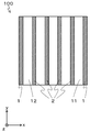
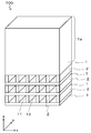
- the particulate matter measuring device component 100 includes a base portion 1 having a flow channel 11 therein and a filter portion 2 provided inside the flow channel 11.
- the particulate matter measuring device component 100 further includes a pair of electrodes 3 for forming a capacitance on the base 1.
- the particulate matter measuring device component 100 is used, for example, to measure the amount of particulate matter in exhaust gas discharged from a diesel engine.
- the holding part 1a is a part for holding the particulate matter measuring device component 100 by a metal member or the like when the part 100 is fixed to the exhaust pipe.
- a metal member or the like only one end portion of the base portion 1 including the flow path 11 and the filter portion 2 can be disposed in the exhaust pipe, and the holding portion 1a can be disposed outside the exhaust pipe. Then, the other end can be held and fixed outside the exhaust pipe by a metal fitting or the like.
- the thermal stress applied between the metal fitting and the particulate matter measuring device part 100 (the holding portion 1a thereof) can be made relatively small, the particulate matter measuring device part 100 can be held.
- the reliability of (attachment), and hence the electrical connection reliability between the particulate matter measuring device component 100 and the external circuit can be improved.
- the wall surface of the flow path 11 of the base portion 1 is denser than the surface of the filter portion 2.
- the particulate matter deposition can be easily concentrated on the filter unit 2, and the linearity between the particulate matter deposition amount and the measured value can be increased.
- the measurement accuracy of the particulate matter measuring device component 100 can be improved.
- the porosity of the wall surface of the flow path 11 of the base 1 By setting the porosity of the wall surface of the flow path 11 of the base 1 to 3% or less, it is possible to make it difficult for particulate matter to enter the base 1. As a result, the possibility that the particulate matter adheres to the electrode 3 can be reduced, so that the electrostatic capacitance between the electrodes 3 may not be correctly measured when the particulate matter adheres to the electrode 3. Can be reduced. As a result, the measurement accuracy of the particulate matter measurement device component 100 can be further improved.
- the base 1 and the filter 2 are made of the same ceramic, the thermal expansion coefficients of the base 1 and the filter 2 can be made closer. Thereby, the long-term reliability of the particulate matter measuring device component 100 under a heat cycle can be improved.
- “consisting of the same ceramics” means that the main components (components occupying 80% by mass or more) of the ceramics constituting the base portion 1 and the filter portion 2 are the same.
- the base 1 and the filter 2 are made of alumina.
- alumina is easy to adjust the surface porosity as shown below.
- the dimensions of the filter portion 2 are, for example, a length along the width direction of the base portion 1 of 0.3 mm, and a length along the thickness direction of the base portion 1 equal to the distance between the bottom surface of the flow path 11 and the ceiling surface.
- the length along the length direction of the base 1 can be set to 40 mm.
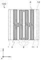
- the electrode 3 is a member for forming a capacitance. As shown in FIG. 2, the electrodes 3 are provided in pairs so that the filter portion 2 is sandwiched between the base portion 1. More specifically, when a plurality of flow paths 11 are provided as in the particulate matter measuring device component 100 of the present disclosure, the filter portions 2 positioned in the respective flow paths 11 are sandwiched. An electrode 3 is provided.
- the electrode 3 may be provided so as to cover the plurality of filter units 2, or may be provided so as to correspond to each of the filter units 2. As shown in FIG. 2, in the case where three flow paths 11 are provided in the vertical direction as in the particulate matter measuring device component 100 of the present disclosure, the electrode 3 is connected to the upper flow path 11.
- the electrode 3 positioned between the upper flow path 11 and the middle flow path 11 can form a capacitance with the upper electrode 3 of the upper flow path 11, and the middle. Capacitance can also be formed between the first channel 11 and the electrode 3 positioned between the lower channel 11. Further, the electrode 3 positioned between the middle flow path 11 and the lower flow path 11 can also form a capacitance with the lower electrode 3 of the lower flow path 11. .
- a capacitance is formed between the pair of electrodes 3 sandwiching the filter unit 2.
- the capacitance between the pair of electrodes 3 changes.
- an external detection device it is possible to measure the amount of particulate matter accumulated in the filter unit 2.
- the electrode 3 is embedded in the base 1. Thereby, the possibility that the electrode 3 may be affected by gas corrosion or the like can be reduced. Moreover, since the possibility that particulate matter or the like adheres to the surface of the electrode 3 can be reduced, the measurement accuracy of the particulate matter measuring device component 100 can be improved.
- the electrode 3 is provided (embedded) inside the base 1, but is not limited thereto. Specifically, the position where the electrode 3 is provided may be, for example, the outer surface of the base 1 (a surface other than the wall surface of the flow path 11).
- the electrode 3 has, for example, a linear wiring pattern and is provided along the filter unit 2.
- the linearity between the amount of the particulate matter collected in the filter part 2 and the change in the capacitance between the electrodes 3 is improved. be able to.
- the shape of the electrode 3 when viewed in plan is not limited to a linear shape, and may be, for example, a circular shape or a rectangular shape.
- the electrode 3 by making the electrode 3 into a linear wiring pattern, the resistance value can be increased as compared with the case where the electrode 3 is made circular or rectangular. Therefore, it is possible to function as a heater by applying a high voltage to the electrode 3. Thereby, the particulate matter collected by the filter part 2 can be removed by heating.
- the electrode 3 has a linear wiring pattern, and is provided in a region of the base portion 1 that sandwiches the filter portion 2 and a region that does not sandwich the filter portion 2.
- a portion of the electrode 3 located in a region where the filter unit 2 is not sandwiched may be narrower than a portion located in a region where the filter unit 2 is sandwiched.
- the width of the portion of the electrode 3 located in the region sandwiching the filter unit 2 is secured to form a good capacitance between the electrodes 3, while the electrode 3 is positioned in the region not sandwiching the filter unit 2
- the resistance value can be increased by narrowing the width of the portion.
- the end portion of the electrode 3 has a lead portion 3 a that is drawn to the base portion 1 located outside the flow path 11 in the width direction (x-axis direction) of the base portion 1. Yes.
- a lead conductor (not shown) is provided that is electrically connected by the lead portion 3 a and passes through the base portion 1 and is drawn to the upper surface of the base portion 1.
- a terminal electrode (not shown) is provided on the upper surface of the base 1 and a through conductor is electrically connected thereto. This terminal electrode can be electrically connected to an external detection device.
- each of the pair of electrodes 3 sandwiching the filter unit 2 has a meander shape meandering by connecting ends of portions provided along each of the plurality of filter units 2. This is a single linear wiring pattern. And the edge part of the one electrode is pulled out by the outer surface of the base 1, and each of one pair of electrodes 3 becomes one line of wiring.
- each of the pair of electrodes 3 is configured by two meander-shaped linear wiring patterns and has two lines of wiring. In the example shown in FIG. 6, the two wiring patterns are arranged side by side in the width direction (x direction) of the flow path 11. In the example shown in FIG. 7, the two wiring patterns are arranged in the length direction of the flow path 11 ( They are arranged side by side in the y-axis direction). In FIGS. 6 and 7, the lead-out portion 3a is omitted.
- each of the pair of electrodes 3 arranged with the filter unit 2 interposed therebetween has two lines of wiring, while detecting the particulate matter with the electrode 3 of one line, Particulate matter collected by the electrode 3 can be removed. Therefore, the particulate matter can be continuously detected without stopping the particulate matter detection for removing the particulate matter.
- each of the pair of electrodes 3 arranged with the filter unit 2 interposed therebetween is a two-line wiring. Wiring may be used.
- the electrode 3 for example, a metal material such as platinum or tungsten can be used. Further, when the electrode 3 has a linear wiring pattern, for example, the width can be set to 2 mm, the length can be set to 38 mm, and the thickness can be set to 30 ⁇ m.
- the base 1 has a shape having the flow path 11 inside, but the present invention is not limited thereto.
- a pair of base portions 1 that are plate-shaped members made of ceramics and are arranged in parallel so that the main surfaces face each other, and a space between the pair of base portions 1 are partitioned.
- a filter portion 2 made of porous ceramics provided so as to form a flow path, and a pair of electrodes for forming a capacitance provided on the pair of base portions 1 so as to sandwich the filter portion 2 therebetween.
- the flow path 11 is provided on one end side of the pair of base portions 1, and the holding portion 1 a may be provided on the other end side of the pair of base portions 1.
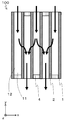
- the flow path 11 (divided flow path 12) is formed by dividing the space between the base 1 and the base 1 by the filter section 2.
- the amount of the particulate matter can be measured by collecting the particulate matter in the flow path 11 and collecting the particulate matter by the filter unit 2 and detecting the change in the capacitance between the electrodes 3.
- the measurement accuracy can be improved in the same manner as the particulate matter measuring device part 100 described above.
- the six bases 1 are arranged in the horizontal direction (x-axis direction) with a total of five spaces, one between each.
- the four filter units 2 are provided in each of the five spaces.
- the number of the base portions 1 may be two to five, or may be seven or more, and the number of the filter portions 2 can be appropriately changed.
- the filter part 2 is provided in the space by the side of the one end part of the base 1 among the space between a pair of bases 1, Thereby, the flow path 11 is formed biased to the one end part side of the base 1. .
- a holding portion 1 a is provided on the other end side of the base portion 1. That is, as in the previous disclosure shown in FIG. 1, the flow path 11 is provided below the base 1 in the height direction (z-axis direction), and above the base 1 in the height direction (z-axis direction). Is provided with a holding portion 1a.
- the holding portion 1a is a portion for holding the particulate matter measuring device component 100 by a metal member or the like when fixing it to the exhaust pipe.
- the holding portion 1a can be disposed outside the exhaust pipe. Then, the other end can be held and fixed outside the exhaust pipe by a metal fitting or the like.
- the thermal stress applied between the metal fitting and the particulate matter measuring device part 100 (the holding portion 1a thereof) can be made relatively small, the particulate matter measuring device part 100 can be held.
- the reliability of (attachment), and hence the electrical connection reliability between the particulate matter measuring device component 100 and the external circuit can be improved.
- the second base portion 1 b made of ceramics similar to the base portion 1 is disposed in the space on the other end side of the base portion 1. And a pair of base 1 and the 2nd base 1b between them are united.
- the holding portion 1a is made of a dense ceramic, the strength of the holding portion 1a to which the metal fitting is attached can be increased, and the holding portion 1a can be held with a stronger force. it can.
- the second base portion 1b can prevent the exhaust gas flowing into the flow path 11 located on the one end side from leaking out of the exhaust pipe from the other end portion.
- the second base portion 1 b is disposed in contact with the filter portion 2 located closest to the other end portion of the base portion 1 in the filter portion 2.
- a space may be provided between the filter portion 2 on the most other end side and the second base portion 1b may be disposed.
- the filter portion 2 also serves as a part of the lower wall, but the base portion 1 that is in contact with the filter portion 2 below the lower filter portion 2 is used as the lower wall. It may be provided. By doing so, the rigidity of the particulate matter measuring device component 100 is improved, and the area where the relatively weak filter part 2 is exposed can be reduced, so that deformation due to thermal stress or external force can be reduced. Damage can be suppressed and the device becomes highly reliable. Moreover, the wall surface which faces the flow path 11 becomes the filter part 2, and the collection efficiency is higher and the sensitivity is better.
- the end of the flow path 11 is open, but the present invention is not limited to this.
- the end portion of the flow path 11 may be partially sealed by the sealing portion 4.
- one end of the flow channel 11 is partially open, and a portion of the other end facing the open portion of one end is sealed. It is preferable that one end portion of the first end portion is partially sealed and a portion of the other end portion that faces the sealed portion of one end portion is open.
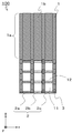
- the particulate matter measuring device component 100 shown in FIGS. 10 to 12 includes a plurality of filters 2 having different degrees of porosity. Particulate material measuring device part 100 that can know the particle size distribution of particulate matter, and particulate material measuring device part 100 that can collect particulate matter continuously for a long time and have a long life. , It can be more value-added.
- the particulate substances collected by the filter portions 2a, 2b, and 2c have different average particle sizes. . Therefore, the particle size distribution of the particulate matter collected from the capacitance detected by the electrodes 3 sandwiching each of the plurality of filter portions 2a, 2b, and 2c having different pore diameters is known.
- the exhaust gas containing particulate matter It is possible to infer the combustion state in the engine that discharges gas and the state of the PM filter located upstream of the particulate matter measuring device component 100.
- the type of pore size of the filter unit 2 is not limited to three, and may be two or four or more.
- the filter portions 2 having the same pore diameter are arranged in a line in the vertical direction (z-axis direction), but may be arranged in a line in the horizontal direction (x-axis direction). Although they may be arranged randomly, they may be arranged in a line as described above.
- the pore diameter here is an average pore diameter.
- the pore diameter may be calculated by taking an SEM image of the surface or cross section of the filter portion 2 and calculating an average pore diameter for pores within the range of the SEM image by image analysis.
- the SEM magnification is 100 times and may be performed using an SEM image having a field of view of 1.0 mm ⁇ 1.3 mm.
- the filter portion 2 has a pore diameter of 1 ⁇ m to 60 ⁇ m and the filter portion 2 has three types of filter portions 2a, 2b, and 2c having different pore diameters as in the above example, for example, the first filter
- the pore diameter of the part 2a may be 10 ⁇ m to 60 ⁇ m
- the pore diameter of the second filter part 2b may be 5 ⁇ m to 30 ⁇ m
- the pore diameter of the third filter part 2c may be 1 ⁇ m to 15 ⁇ m.
- located outside here may be the outside in the vertical direction as shown in FIG. Further, “located outside” may be the outside in the width direction of the flow path space 10 as shown in FIG. 12. Further, “located outside” may be the outside in the entire vertical direction and width direction.
- the fourth filter portion 2d is disposed outside the vertical direction (z-axis direction), and the fifth filter portion 2e is disposed inside.
- Three rows of spaces (channels 11) are arranged in the left-right direction (x-axis direction) in the drawing, and six filter sections 2 are arranged in the vertical direction (z-axis direction) in each space (channel 11). ing.
- the upper two and the lower two in each space are the fourth filter portions 2d, and the center two in each space are the fifth filter portions 2e.
- the fourth filter portion 2d is disposed outside the left and right direction (x-axis direction) of the drawing, and the fifth filter portion 2e is disposed inside.
- Three rows of spaces are arranged in the left-right direction (x-axis direction), and four filter units 2 are arranged in each space in the vertical direction (z-axis direction). Of the three spaces, four of the four spaces located in the left and right spaces are the fourth filter portions 2d, and four of the three spaces located in the central space are the fifth filter portions 2e.
- the central portion of the space inside the cross section perpendicular to the length direction of the flow path 11
- the flow rate of the gas flowing through the region tends to be larger than the flow rate of the gas flowing through the outer periphery of the space (the outer region in a cross-sectional view perpendicular to the length direction of the flow path 11).
- the inner filter portion 2 collects more particulate matter than the outer filter portion 2, and the clogging of the particulate matter is also accelerated.
- the frequency of performing the regeneration for removing the particulate matter by heating with the heater is increased, so that the deterioration of the particulate matter measuring device component 100 is also accelerated.
- the porosity of the filter unit 2 (fourth filter unit 2 d) located outside is the filter unit located inside. 2 (fifth filter portion 2e) is larger than the porosity of the filter portion 2 (fourth filter portion 2d) having a larger porosity, the gas is more likely to flow and is perpendicular to the length direction of the flow path 11. The difference in gas flow rate depending on the position in the cross section is reduced. Therefore, since only the inner filter part 2 is not quickly clogged with particulate matter, it is possible to collect particulate matter continuously for a long time, and the long-life particulate matter measuring device component 100 and become.
- the porosity of the filter unit 2 located on the outer side in the up-down direction and the outer side in the left-right direction is the filter unit 2 (fifth filter unit) located on the inner side, respectively. 2e)
- the porosity of the filter part 2 located on the outer side in the vertical and horizontal directions and the outer periphery in the cross-section is combined in the center in the vertical and horizontal directions and in the center in the cross-section. It may be larger than the porosity of the filter part 2 located.
- the base 1 and the filter unit 2 are alternately arranged in the left-right direction (x-axis direction)
- the fourth filter is placed outside the left-right direction (x-axis direction) as in the example shown in FIG.
- the structure in which the part 2d is arranged and the fifth filter part 2e is arranged inside may be easily manufactured by a manufacturing method as described later.
- Examples of the porosity measurement method for comparing the porosity of the filter unit 2 include a mercury intrusion method (JIS standard R1655: 2003), image analysis of SEM images, and the like.
- the image analysis of the SEM image can be performed by taking a SEM image of a cross section of the filter unit 2 and calculating the area ratio of the pores within the range of the SEM image by image analysis.
- the SEM magnification is 100 times, and an SEM image having a field of view of 1.0 mm ⁇ 1.3 mm may be used.
- the porosity of the filter unit 2 is 40 to 70%
- the porosity of the filter unit 2d having a relatively high porosity and the filter unit 2e having a relatively low porosity are 50 to 70% and 40 to 60, respectively. %And it is sufficient.
- the flow path 11 has been described as an example extending from one side surface of the base 1 to the side surface at a position opposite thereto, but is not limited thereto. .
- the flow path 11 may have one end opened on one side surface of the base 1 and the other end opened on a surface (lower surface) positioned at one end of the base 1. Good. Or you may open to the surface (lower surface) located in the two side surfaces which the base 1 opposes, and the one end part of the base 1.
- a particulate material comprising a pair of base portions 1 juxtaposed so that the main surfaces face each other and a filter portion 2 provided so as to form a flow path 11 by dividing a space between the pair of base portions 1.
- the example shown in FIG. 8 is an example in which the base 1 and the filter unit 2 are alternately arranged in the horizontal direction (x-axis direction), but like the example shown in FIG.
- the base portions 1 and the filter portions 2 may be alternately arranged in the vertical direction (z-axis direction).
- the holding portion 1a does not have the second base portion 1b.
- the thickness of the base part 1 located on the outermost side (upper side) is thick, and this part is the holding part 1a.
- the portion located outside the flow path 11 in the base 1 and the outer wall of the flow path 11 are the same as those replaced with the filter portion 2.
- the method for manufacturing the particulate matter measuring device component 100 in which the dense base portion 1 made of ceramics and the filter portion 2 made of porous ceramics are integrally formed as described above is, for example, a plurality of first methods.
- a step of firing the laminate 102 is, for example, a plurality of first methods.
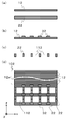
- FIG. 15 is a schematic diagram showing a method for manufacturing a particulate matter measuring device part for each step.
- FIG. 15 shows a part 100 for a particulate matter measuring apparatus as in the example shown in FIG. 8, wherein the number of base portions 1 is changed from six to three, and the number of filter portions 2 arranged between the pair of base portions 1 is changed from four. The process of manufacturing what was made into six is shown.
- a plurality of first ceramic green sheets 12, a plurality of second ceramic green sheets 22, and a third ceramic green sheet 12b are prepared.
- the first ceramic green sheet 12 is a part that is sintered in the subsequent firing step to become the base 1, and the second ceramic green sheet 22 is a part that similarly becomes the filter part 2, and the third ceramic
- the green sheet 12b is a portion that becomes the second base 2b.
- the filter part 2 is made of porous ceramics. Therefore, the second ceramic green sheet 22 has more pores (the porosity becomes larger) when sintered in the subsequent firing step with respect to the first ceramic green sheet 12 and the third ceramic green sheet 12b.
- the second ceramic green sheet 22 contains more components that become pores when sintered in the firing step than the first ceramic green sheet 12 and the third ceramic green sheet 12b. It is a waste. Specifically, those having a large organic binder component, those containing a pore former, and the like. Alternatively, in order to decrease the sinterability and increase the pores, there are few sintering aid components.
- first ceramic green sheet 12 and the third ceramic green sheet 12b are made of alumina ceramics
- first, alumina powder and sintering aid powder such as SiO 2 , MgO, CaO
- a slurry is prepared by mixing an organic binder such as acrylic resin, an organic solvent such as toluene and acetone, and a solvent such as water.
- the slurry may be used to form a sheet by a film forming method such as a doctor blade method.
- the first ceramic green sheet 12 and the third ceramic green sheet 12 b have different thicknesses, but may have the same thickness.
- the first ceramic green sheet 12 and the third ceramic green sheet 12b have different sizes, and the third ceramic green sheet 12b is smaller.
- the second ceramic green sheet 22 may be a slurry obtained by adding a pore former to the slurry for the first ceramic green sheet 12.
- the second ceramic green sheet 22 includes a pore former with respect to the first ceramic green sheet 12.
- the second ceramic green sheet 22 is also smaller than the first ceramic green sheet 12.
- the size in which the second ceramic green sheet 22 and the third ceramic green sheet 12 b are arranged is approximately the same as that of the first ceramic green sheet 12.
- the filter part 2 has different pore diameters, for example, as the pore former added to the slurry for the second ceramic green sheet 22, those having different average particle diameters are used. What is necessary is just to produce several types of 2nd ceramic green sheets 22 from which an average particle diameter differs.
- the filter unit 2 has different porosity, for example, the amount of pore forming material added to the slurry for the second ceramic green sheet 22 is different from each other, the average particle size of the included pore forming material is different, A plurality of types of second ceramic green sheets 22 may be produced.
- an electrode layer 32 is formed on the first ceramic green sheet 12 as in the example shown in FIG.
- the electrode layer 32 is sintered in the subsequent firing step to become the electrode 3.
- the electrode layer 32 may be formed by applying a metal paste mainly composed of a metal material such as platinum or tungsten which is the main component of the electrode 3 on the first ceramic green sheet 12.
- the metal paste can be prepared by adding a resin binder and a solvent to a metal material powder and kneading. What is necessary is just to apply
- the through-hole 112 is formed in the second ceramic green sheet 22.
- the through hole 112 is a portion that becomes the flow path 11.
- the through holes 112 may be formed in the second ceramic green sheet 22 by punching using a mold or laser processing.
- the laminated body 102 is formed by laminating the sheet 12b.
- the portions to be the three substrates 1 are each formed by laminating two layers of the first ceramic green sheets 12, and the portion to be the filter portion 2 is the two layers of the second ceramic.
- the green sheet 22 is formed by being laminated. In either case, a ceramic green sheet having one layer or three or more layers may be used.
- the first electrode layer 32 is not formed on the first ceramic green sheet 12 on which the electrode layer 32 is formed.
- the ceramic green sheets 12 are stacked, only the portion of the second ceramic green sheet 22 that becomes the filter portion 2 is stacked, and further the frame-shaped first ceramic green sheet 12 is stacked so as to surround the periphery. Good.
- Base 1a Holding unit 1b: Second base 11: Channel 12: Divided channel 2: Filter unit 3: Electrode 4: Sealing unit 100: Particulate material measuring device component
Landscapes
- Chemical & Material Sciences (AREA)
- Engineering & Computer Science (AREA)
- Pathology (AREA)
- Biochemistry (AREA)
- Immunology (AREA)
- General Physics & Mathematics (AREA)
- General Health & Medical Sciences (AREA)
- Physics & Mathematics (AREA)
- Health & Medical Sciences (AREA)
- Life Sciences & Earth Sciences (AREA)
- Analytical Chemistry (AREA)
- Mechanical Engineering (AREA)
- Chemical Kinetics & Catalysis (AREA)
- General Engineering & Computer Science (AREA)
- Combustion & Propulsion (AREA)
- Electrochemistry (AREA)
- Dispersion Chemistry (AREA)
- Power Engineering (AREA)
- Investigating Or Analyzing Materials By The Use Of Electric Means (AREA)
- Processes For Solid Components From Exhaust (AREA)
- Exhaust Gas After Treatment (AREA)
- Sampling And Sample Adjustment (AREA)
Abstract
Description
1a:保持部
1b:第2の基部
11:流路
12:分割流路
2:フィルタ部
3:電極
4:封止部
100:粒子状物質の測定装置用部品
Claims (12)
- セラミックスから成り内部にガスの流れる流路を有する基部と、前記流路を複数に区切るように前記流路の内部に設けられた多孔質セラミックスから成るフィルタ部と、前記基部に前記フィルタ部を挟むように設けられた静電容量形成用の一対の電極とを備えており、
前記流路は前記基部の一端部側に設けられており、前記基部の他端部側には保持部が設けられている粒子状物質の測定装置用部品。 - セラミックスから成り内部にガスの流れる流路を有する基部と、前記流路を複数に区切るように前記流路の内部に設けられた多孔質セラミックスから成るフィルタ部と、前記基部に前記フィルタ部を挟むように設けられた静電容量形成用の一対の電極とを備えており、
前記基部は前記流路の長さ方向に垂直な高さ方向を有しており、前記基部を高さ方向に2分したときに、前記流路は前記2分された基部の一方にのみ設けられている粒子状物質の測定装置用部品。 - セラミックスから成る板状の部材であって主面が対向するように並置された一対の基部と、該一対の基部の間の空間を区切って流路を形成するように設けられた多孔質セラミックスから成るフィルタ部と、前記一対の基部にそれぞれ設けられており前記フィルタ部を挟むように設けられた静電容量形成用の一対の電極とを備えており、
前記流路は前記一対の基部の一端部側に設けられており、前記一対の基部の他端部側には保持部が設けられている粒子状物質の測定装置用部品。 - 前記基体の前記他端部側における前記空間には、セラミックスから成る第2の基部が配置されている請求項3に記載の粒子状物質の測定装置用部品。
- 前記電極が前記基部に埋設されている請求項1乃至請求項4のいずれかに記載の粒子状物質の測定装置用部品。
- 前記基部および前記フィルタ部が一体的に形成されている請求項1乃至請求項5のいずれかに記載の粒子状物質の測定装置用部品。
- 前記基部および前記フィルタ部が同じセラミックスから成る請求項1乃至請求項6のいずれかに記載の粒子状物質の測定装置用部品。
- 前記基部および前記フィルタ部がアルミナから成る請求項7に記載の粒子状物質の測定装置用部品。
- 前記電極が、線状の配線パターンを有するとともに、前記フィルタ部に沿って設けられている請求項1乃至請求項8のいずれかに記載の粒子状物質の測定装置用部品。
- 前記電極が線状の配線パターンを有するとともに、前記基部のうち前記フィルタ部を挟む領域および前記フィルタ部を挟まない領域に設けられており、平面視したときに、前記電極のうち前記フィルタ部を挟まない領域に位置する部分が、前記フィルタ部を挟む領域に位置する部分よりも幅が狭くなっている請求項1乃至請求項9のいずれかに記載の粒子状物質の測定装置用部品。
- 互いに気孔径が異なる複数の前記フィルタ部を有している請求項1乃至10のいずれかに記載の粒子状物質の測定装置用部品。
- 前記流路の長さ方向に垂直な断面視において、外側に位置する前記フィルタ部の気孔率が、内側に位置する前記フィルタ部の気孔率より大きい請求項1乃至10のいずれかにの粒子状物質の測定装置用部品。
Priority Applications (4)
| Application Number | Priority Date | Filing Date | Title |
|---|---|---|---|
| CN201680075617.7A CN108431588A (zh) | 2015-12-25 | 2016-12-13 | 粒子状物质的测量装置用部件 |
| JP2017557895A JP6542913B2 (ja) | 2015-12-25 | 2016-12-13 | 粒子状物質の測定装置用部品 |
| US16/065,265 US20210172365A1 (en) | 2015-12-25 | 2016-12-13 | Particulate matter measuring device component |
| EP16878472.6A EP3396366A4 (en) | 2015-12-25 | 2016-12-13 | COMPONENT FOR PARTICLE MEASURING DEVICE |
Applications Claiming Priority (2)
| Application Number | Priority Date | Filing Date | Title |
|---|---|---|---|
| JP2015254148 | 2015-12-25 | ||
| JP2015-254148 | 2015-12-25 |
Publications (1)
| Publication Number | Publication Date |
|---|---|
| WO2017110581A1 true WO2017110581A1 (ja) | 2017-06-29 |
Family
ID=59090207
Family Applications (1)
| Application Number | Title | Priority Date | Filing Date |
|---|---|---|---|
| PCT/JP2016/087048 Ceased WO2017110581A1 (ja) | 2015-12-25 | 2016-12-13 | 粒子状物質の測定装置用部品 |
Country Status (5)
| Country | Link |
|---|---|
| US (1) | US20210172365A1 (ja) |
| EP (1) | EP3396366A4 (ja) |
| JP (1) | JP6542913B2 (ja) |
| CN (1) | CN108431588A (ja) |
| WO (1) | WO2017110581A1 (ja) |
Families Citing this family (1)
| Publication number | Priority date | Publication date | Assignee | Title |
|---|---|---|---|---|
| CN120293235B (zh) * | 2025-06-12 | 2025-08-15 | 太原市水文水资源勘测站 | 一种江河水文检测用智能泥沙流量实时监测装置 |
Citations (4)
| Publication number | Priority date | Publication date | Assignee | Title |
|---|---|---|---|---|
| JP2007524786A (ja) * | 2004-02-12 | 2007-08-30 | ダイムラークライスラー・アクチェンゲゼルシャフト | パティキュレートフィルタの状態判定装置 |
| JP2009006326A (ja) * | 2002-03-29 | 2009-01-15 | Ibiden Co Ltd | セラミックフィルタおよび排ガス浄化装置 |
| JP2014159783A (ja) | 2013-02-20 | 2014-09-04 | Isuzu Motors Ltd | 粒子状物質の測定装置 |
| JP2015066517A (ja) * | 2013-09-30 | 2015-04-13 | 京セラ株式会社 | ハニカム構造体およびこれを用いたガス処理装置 |
Family Cites Families (4)
| Publication number | Priority date | Publication date | Assignee | Title |
|---|---|---|---|---|
| JP2004360512A (ja) * | 2003-06-03 | 2004-12-24 | Hino Motors Ltd | 排気浄化装置 |
| JP5565005B2 (ja) * | 2010-03-10 | 2014-08-06 | いすゞ自動車株式会社 | Dpf故障検出方法及びdpf故障検出装置 |
| JP6028615B2 (ja) * | 2013-02-20 | 2016-11-16 | いすゞ自動車株式会社 | 粒子状物質の測定装置 |
| JP6626901B2 (ja) * | 2015-11-26 | 2019-12-25 | 京セラ株式会社 | 粒子状物質の測定装置用部品およびその製造方法 |
-
2016
- 2016-12-13 WO PCT/JP2016/087048 patent/WO2017110581A1/ja not_active Ceased
- 2016-12-13 JP JP2017557895A patent/JP6542913B2/ja not_active Expired - Fee Related
- 2016-12-13 EP EP16878472.6A patent/EP3396366A4/en not_active Withdrawn
- 2016-12-13 CN CN201680075617.7A patent/CN108431588A/zh active Pending
- 2016-12-13 US US16/065,265 patent/US20210172365A1/en not_active Abandoned
Patent Citations (4)
| Publication number | Priority date | Publication date | Assignee | Title |
|---|---|---|---|---|
| JP2009006326A (ja) * | 2002-03-29 | 2009-01-15 | Ibiden Co Ltd | セラミックフィルタおよび排ガス浄化装置 |
| JP2007524786A (ja) * | 2004-02-12 | 2007-08-30 | ダイムラークライスラー・アクチェンゲゼルシャフト | パティキュレートフィルタの状態判定装置 |
| JP2014159783A (ja) | 2013-02-20 | 2014-09-04 | Isuzu Motors Ltd | 粒子状物質の測定装置 |
| JP2015066517A (ja) * | 2013-09-30 | 2015-04-13 | 京セラ株式会社 | ハニカム構造体およびこれを用いたガス処理装置 |
Non-Patent Citations (1)
| Title |
|---|
| See also references of EP3396366A4 |
Also Published As
| Publication number | Publication date |
|---|---|
| JP6542913B2 (ja) | 2019-07-10 |
| US20210172365A1 (en) | 2021-06-10 |
| CN108431588A (zh) | 2018-08-21 |
| EP3396366A1 (en) | 2018-10-31 |
| JPWO2017110581A1 (ja) | 2018-10-04 |
| EP3396366A4 (en) | 2019-06-26 |
Similar Documents
| Publication | Publication Date | Title |
|---|---|---|
| US9528971B2 (en) | Particulate matter detection element and method of manufacturing same | |
| JP6626901B2 (ja) | 粒子状物質の測定装置用部品およびその製造方法 | |
| TWI612286B (zh) | 用於檢測導電性和/或可極化粒子的感測器、感測系統、操作感測器的方法、此感測器的製造方法及此感測器的應用(二) | |
| JP5542007B2 (ja) | 粒子状物質検出装置 | |
| JP5542006B2 (ja) | 粒子状物質検出装置 | |
| JP6536507B2 (ja) | 粒子状物質検出センサ | |
| JP2012058015A (ja) | 粒子状物質検出装置 | |
| JP2012117383A (ja) | Pmセンサ及びpmセンサ製造方法 | |
| WO2016063737A1 (ja) | 粒子状物質検出センサ | |
| JP6920451B2 (ja) | 測定装置用部品 | |
| JP6542913B2 (ja) | 粒子状物質の測定装置用部品 | |
| JP5864368B2 (ja) | 粒子状物質検出素子並びにその製造方法 | |
| JP6711846B2 (ja) | 粒子状物質の測定装置用部品 | |
| CN108369203A (zh) | 传感器元件用电极及传感器元件 | |
| WO2016080120A1 (ja) | 粒子状物質検出センサ | |
| KR101652981B1 (ko) | 입자상 물질 센서 | |
| WO2016175022A1 (ja) | 粒子状物質検出センサ | |
| WO2016185841A1 (ja) | 粒子状物質検出センサ | |
| CN115494541A (zh) | 多气隙阻性板室探测器 | |
| JP6435198B2 (ja) | 粒子状物質検出センサ | |
| JP5071253B2 (ja) | セラミックヒータの製造方法 | |
| JP2009176767A (ja) | 積層セラミックコンデンサの製造方法 | |
| JP2020063927A (ja) | 粒子状物質検出システム、粒子状物質検出システムの制御方法およびプログラム | |
| JP2020063681A (ja) | 粒子状物質検出システム、粒子状物質検出システムの制御方法およびプログラム | |
| JP2000012376A (ja) | 積層セラミック電子部品及びその製造方法 |
Legal Events
| Date | Code | Title | Description |
|---|---|---|---|
| 121 | Ep: the epo has been informed by wipo that ep was designated in this application |
Ref document number: 16878472 Country of ref document: EP Kind code of ref document: A1 |
|
| ENP | Entry into the national phase |
Ref document number: 2017557895 Country of ref document: JP Kind code of ref document: A |
|
| NENP | Non-entry into the national phase |
Ref country code: DE |
|
| WWE | Wipo information: entry into national phase |
Ref document number: 2016878472 Country of ref document: EP |
|
| ENP | Entry into the national phase |
Ref document number: 2016878472 Country of ref document: EP Effective date: 20180725 |