WO2017113815A1 - 毫米波三维全息扫描成像设备 - Google Patents
毫米波三维全息扫描成像设备 Download PDFInfo
- Publication number
- WO2017113815A1 WO2017113815A1 PCT/CN2016/096000 CN2016096000W WO2017113815A1 WO 2017113815 A1 WO2017113815 A1 WO 2017113815A1 CN 2016096000 W CN2016096000 W CN 2016096000W WO 2017113815 A1 WO2017113815 A1 WO 2017113815A1
- Authority
- WO
- WIPO (PCT)
- Prior art keywords
- millimeter wave
- antenna array
- receiving antenna
- transmitting
- dimensional holographic
- Prior art date
- Legal status (The legal status is an assumption and is not a legal conclusion. Google has not performed a legal analysis and makes no representation as to the accuracy of the status listed.)
- Ceased
Links
Images


Classifications
-
- G—PHYSICS
- G01—MEASURING; TESTING
- G01S—RADIO DIRECTION-FINDING; RADIO NAVIGATION; DETERMINING DISTANCE OR VELOCITY BY USE OF RADIO WAVES; LOCATING OR PRESENCE-DETECTING BY USE OF THE REFLECTION OR RERADIATION OF RADIO WAVES; ANALOGOUS ARRANGEMENTS USING OTHER WAVES
- G01S13/00—Systems using the reflection or reradiation of radio waves, e.g. radar systems; Analogous systems using reflection or reradiation of waves whose nature or wavelength is irrelevant or unspecified
- G01S13/88—Radar or analogous systems specially adapted for specific applications
- G01S13/89—Radar or analogous systems specially adapted for specific applications for mapping or imaging
-
- G—PHYSICS
- G01—MEASURING; TESTING
- G01S—RADIO DIRECTION-FINDING; RADIO NAVIGATION; DETERMINING DISTANCE OR VELOCITY BY USE OF RADIO WAVES; LOCATING OR PRESENCE-DETECTING BY USE OF THE REFLECTION OR RERADIATION OF RADIO WAVES; ANALOGOUS ARRANGEMENTS USING OTHER WAVES
- G01S13/00—Systems using the reflection or reradiation of radio waves, e.g. radar systems; Analogous systems using reflection or reradiation of waves whose nature or wavelength is irrelevant or unspecified
- G01S13/88—Radar or analogous systems specially adapted for specific applications
- G01S13/887—Radar or analogous systems specially adapted for specific applications for detection of concealed objects, e.g. contraband or weapons
-
- G—PHYSICS
- G01—MEASURING; TESTING
- G01S—RADIO DIRECTION-FINDING; RADIO NAVIGATION; DETERMINING DISTANCE OR VELOCITY BY USE OF RADIO WAVES; LOCATING OR PRESENCE-DETECTING BY USE OF THE REFLECTION OR RERADIATION OF RADIO WAVES; ANALOGOUS ARRANGEMENTS USING OTHER WAVES
- G01S7/00—Details of systems according to groups G01S13/00, G01S15/00, G01S17/00
- G01S7/02—Details of systems according to groups G01S13/00, G01S15/00, G01S17/00 of systems according to group G01S13/00
Definitions
- the invention relates to the technical field of security inspection, in particular to a millimeter wave three-dimensional holographic scanning imaging device.
- the human body security inspection equipment mainly includes an X-ray backscattering human body imaging device and a millimeter wave human body imaging device. X-ray backscattering human body imaging equipment uses X-rays incident on the surface of the human body to scatter the signal for imaging. Since X-rays have ionization properties, they are susceptible to public questioning in terms of safety.
- Millimeter wave human imaging equipment mainly includes active and passive.
- the image quality of active millimeter wave imaging is obviously better than passive imaging.
- the good imaging effect ensures high recognition rate of contraband. Therefore, active millimeter wave human security equipment has gradually become the mainstream development direction of human security equipment.
- the active millimeter wave imaging technology is based on holographic imaging technology.
- cylindrical scanning imaging technology In the active millimeter-wave three-dimensional holographic imaging technology applied to human body security, cylindrical scanning imaging technology is widely used, but its equipment covers a large area and it is difficult to complete the imaging of the object to be measured.
- An object of the present invention is to provide a millimeter wave three-dimensional holographic scanning imaging apparatus capable of rapidly and efficiently performing millimeter wave three-dimensional holographic scanning imaging on each side of an object to be measured such as a human body or an article.
- Embodiments of the present invention provide a millimeter wave three-dimensional holographic scanning imaging apparatus, including:
- At least one millimeter wave transceiver and at least one millimeter wave transceiver antenna array electrically coupled to the at least one millimeter wave transceiver, the at least one millimeter wave transceiver antenna array for transmitting and receiving at least one millimeter wave signal, respectively;
- At least one guiding device the at least one millimeter wave transmitting and receiving antenna array is respectively connected to the at least one guiding device to be capable of scanning with the at least one guiding device to scan a circumferential side of the object to be tested, the at least one millimeter wave
- the extending direction of the transceiver antenna array is perpendicular to the at least one guiding device;
- a driving device for driving the at least one guiding device to move to drive the at least one millimeter wave transmitting and receiving antenna array to scan along a linear trajectory
- a housing surrounding the detection area of the object to be tested at the time of detection, the housing being formed with an inlet for the object to be tested to enter the detection area and an outlet for the object to be tested to leave the detection area.
- the scanning directions of the at least one millimeter wave transmitting and receiving antenna array are both vertical directions, and the at least one millimeter wave transmitting and receiving antenna array extends in a horizontal direction.
- the at least one millimeter wave transceiving antenna array comprises a circular shaped millimeter wave transceiving antenna array.
- the inlet and the outlet are respectively located on both sides of the detection area.
- the millimeter wave three-dimensional holographic scanning imaging device further includes:
- first door device and the second door device are configured to be turned off when the at least one millimeter wave transceiver antenna array is scanned and opened before or after the at least one millimeter wave transceiver antenna array is scanned.
- each of the first door device and the second door device has a first wall and a second wall, and at least one of the millimeter wave transceiver antenna arrays is capable of being from the first wall and the Scanning between the two walls.
- the first wall is closer to the detection zone relative to the second wall, the first wall being at least partially transparent to the millimeter wave signal.
- the at least one millimeter wave transceiver antenna array comprises a first millimeter wave transceiver antenna array and a second millimeter wave transceiver antenna array, wherein the first millimeter wave transceiver antenna array is configured to transmit and receive the first millimeter wave a second millimeter wave transceiver antenna array for transmitting and receiving a second millimeter wave signal;
- the at least one guiding device includes a first guiding device and a second guiding device, the first millimeter wave transmitting and receiving antenna array being coupled to the first guiding device to be movable with the first guiding device in a first scanning trajectory Scanning a first side of the object to be measured, the second millimeter wave transceiver antenna array being coupled to the second guiding device to be movable with the second guiding device in a second scanning trajectory to the object to be tested The second side scans.
- the first millimeter wave transceiver antenna array and the second millimeter wave transceiver antenna array combine to form a complete enclosure of the object to be tested.
- the first millimeter wave transceiver antenna array and the second millimeter wave transceiver antenna array each have a circular arc shape.
- the inlet and the outlet are respectively located on both sides of the detection area.
- the first millimeter wave transmitting and receiving antenna array has a circular arc shape
- the second millimeter wave transmitting and receiving antenna array has a linear shape
- the inlet and the outlet are disposed on the same side of the detection area.
- the millimeter wave three-dimensional holographic scan imaging apparatus further includes a revolving door having a first rotational position and a second rotational position, in the first rotational position, the revolving door closes the An inlet and the outlet, and in the second rotational position, the revolving door opens the inlet and the outlet, the revolving door being disposed at a second millimeter wave transmitting and receiving antenna array of a millimeter wave three-dimensional holographic scanning imaging device One side.
- the inlet and the outlet are both located between the first millimeter wave transceiver antenna array and the second millimeter wave transceiver antenna array.
- the drive device includes a drive wheel
- the guide device includes a drive line that engages the drive wheel
- the above at least one embodiment of the present invention is capable of simultaneously scanning the circumferential side of the object to be measured by at least one millimeter wave transmitting and receiving antenna array and improving the detection efficiency and reducing the volume of the apparatus by appropriately setting the inlet and the outlet.
- FIG. 1 shows a schematic structural view of a millimeter wave three-dimensional holographic scanning imaging apparatus according to an embodiment of the present invention
- 1a is a schematic structural view showing a first door device or a second door device in a millimeter wave three-dimensional holographic scanning imaging device according to an embodiment of the present invention
- FIG. 2 shows a schematic diagram of a millimeter wave three-dimensional holographic scanning imaging apparatus according to another embodiment of the present invention
- FIG. 3 shows a schematic diagram of a millimeter wave three-dimensional holographic scanning imaging apparatus according to still another embodiment of the present invention
- 4-6 respectively show schematic top views of various examples of the arrangement of the millimeter wave transceiving antenna array and the inlet and outlet in the millimeter wave three-dimensional holographic scanning imaging apparatus according to an embodiment of the present invention.
- a millimeter wave three-dimensional holographic scanning imaging apparatus comprising: at least one millimeter wave transceiver and at least one millimeter wave transmitting and receiving antenna array electrically connected correspondingly to the at least one millimeter wave transceiver
- the at least one millimeter wave transceiver antenna array is configured to transmit and receive at least one millimeter wave signal, respectively; at least one guiding device, wherein the at least one millimeter wave transceiver antenna array is respectively connected to the at least one guiding device to be capable of a guiding device is moved to scan the circumference of the object to be tested, the extending direction of the at least one millimeter wave transmitting and receiving antenna array is perpendicular to the at least one guiding device, respectively; and driving means for driving the at least one guiding device to move Driving the at least one millimeter wave transceiver antenna array to scan along a linear trajectory; and housing, the housing surrounding the detection of the object to be tested at the time of detection In the area
- FIG. 1 schematically illustrates a millimeter wave three-dimensional holographic scan imaging apparatus 100 in accordance with an embodiment of the present invention.
- the millimeter wave three-dimensional holographic scanning imaging apparatus 100 may include a millimeter wave transceiver 10 and a millimeter wave transmitting and receiving antenna array 20 electrically connected to the millimeter wave transceiver 10, the millimeter wave transmitting and receiving antenna array 20 for transmitting and Receiving the millimeter wave signal; the guiding device 30, the millimeter wave transmitting and receiving antenna array 20 is connected to the guiding device 30 so as to be movable with the guiding device 30 to scan the circumferential side of the object to be tested 90, and the extending direction of the millimeter wave transmitting and receiving antenna array 20 is
- the guiding device 30 is vertical;
- the driving device 40 (such as a driving wheel and its motor, etc.) is used to drive the guiding device 30 to move to drive the millimeter wave transmitting and receiving antenna array 20 to scan along a linear trajectory; and the
- the millimeter wave three-dimensional holographic scanning imaging apparatus employs a structure having independent inlets 92 and outlets 93, and an object to be tested (for example, a person or an article) can be easily accessed from the inlet 92 before inspection, while inspecting Then exit from exit 93.
- an object to be tested for example, a person or an article
- the object to be tested can enter and leave the detection area without turning, which improves the inspection efficiency. This is especially advantageous for security inspections of crowded places such as airports and stations.
- the scanning direction of the millimeter wave transmitting and receiving antenna array 20 is a vertical direction, and the millimeter wave transmitting and receiving antenna array 20 extends in the horizontal direction.
- This arrangement facilitates the scanning of the circumference of the object to be tested conveniently.
- the millimeter wave transmitting and receiving antenna array 20 has a ring shape.
- the circular-shaped millimeter wave transceiver antenna array 20 completely surrounds the object to be tested, and only needs to perform a top-to-bottom (or bottom-up) scan to complete the acquisition of millimeter wave data for all sides of the object to be tested.
- the circular-shaped millimeter-wave transmitting/receiving antenna array 20 can be divided into a plurality of independent circular-arc-shaped millimeter-wave transmitting/receiving antenna arrays 20 in the circumferential direction, and the scanning of the object to be tested can also be completed.
- the weight of the single millimeter wave transmitting and receiving antenna array 20 can be alleviated, and the flexibility of operation can be improved.
- the inlet 92 and the outlet 93 are respectively located on both sides of the detection area 91, as shown in FIGS. 1-2. This helps to improve the efficiency of the object to be tested passing through the detection area 91, especially when the object to be tested needs to be queued for detection.
- the millimeter wave three-dimensional holographic scan imaging apparatus 100 may further include: a first door device 51 disposed at the inlet 92 and a second door device 52 disposed at the outlet 93.
- the first door device 51 and the second door device 52 are configured to be turned off when the millimeter wave transmitting and receiving antenna array 20 performs scanning and opened before or after the millimeter wave transmitting and receiving antenna array 20 is scanned.
- the first door device 51 and the second door device 52 are capable of providing a closed environment for the detection area 91 when the millimeter wave transceiver antenna array 20 is scanned.
- the first door device 51 and the second door device 52 can prevent the millimeter wave transmitting and receiving antenna array 20 from being exposed to the object to be tested 90 during scanning. To avoid the danger or adversely affect the subject 90 to be tested.
- the millimeter wave transceiver antenna array 20 can be hidden at the top or bottom end of the casing 50 without hindering the object to be tested 90 from passing through the inlet 92 or the outlet 93.
- each of the first door device 51 and the second door device 52 may have a first wall 53 and a second wall 54, from which the millimeter wave transceiver antenna array 20 can be from the first wall 53 and the second wall Scan between 54 passes. This can prevent the millimeter wave transmitting and receiving antenna array 20 from being exposed to persons outside the object to be tested or the millimeter wave three-dimensional holographic scanning imaging device to avoid accidents.
- the housing 50 can also employ a double wall structure similar to the first door device 51 and the second door device 52 to accommodate the millimeter wave transceiver antenna array 20 between the double walls.
- the first wall 53 is closer to the detection region 91 relative to the second wall 54, the first wall 53 being at least partially transparent to the millimeter wave signal, for example completely transparent. This can ensure smooth transmission and reception of the millimeter wave signal by the millimeter wave transmitting and receiving antenna array 20.
- the second wall 54 can have a shielding effect on the millimeter wave signal to prevent the millimeter wave signal from interfering with the surrounding environment.
- the first door device 51 and the second door device 52 may be arcuate automatic doors.
- the millimeter wave three-dimensional holographic scan imaging apparatus 100 may further include a data processing device 70.
- the data processing device 70 is wirelessly or wiredly coupled to the millimeter wave transceiver to receive scan data from the millimeter wave transceiver for each side of the object to be tested and to generate a millimeter wave holographic image.
- the millimeter wave three-dimensional holographic scan imaging apparatus 100 may further include a display device 80. Display device 80 is coupled to data processing device 70 for receiving and displaying millimeter wave holographic images from data processing device 70.
- data processing device 70 can be used to control drive device 40 to drive millimeter wave transmit and receive antenna array 20 motion.
- the millimeter wave three-dimensional holographic scan imaging apparatus 100 may also include a control device 71 that is separate from the data processing device 70.
- the drive unit 40 can include drive wheels 41-42 that can be rotated by the drive shaft and drive motor. It is also possible to provide some of the driven wheels 43, 44 as needed. Although two driving wheels 41-42 and two driven wheels 43, 44 are shown in FIG. 1, in the embodiment of the present invention, the number of driving wheels and driven wheels is not limited thereto, and one or two may be employed. , three or more than four drive wheels or driven wheels. In the case of multiple drive wheels, these drive wheels can work independently or together.
- the guiding device 30 can include a drive cable that engages the drive wheels 41-42, such as belts, cables, etc., as known in the art that can be used to implement the transmission functions described above.
- a drive cable that engages the drive wheels 41-42, such as belts, cables, etc., as known in the art that can be used to implement the transmission functions described above.
- the millimeter wave transceiver antenna array 20 may be fixed to the guiding device 30 by fixing means 35, 36.
- the fixtures 35, 36 may include slides, clips, and the like.
- Fig. 2 shows a millimeter wave three-dimensional holographic scan imaging apparatus 100' according to another embodiment.
- a first millimeter wave transmitting and receiving antenna array 21 and a second millimeter wave transmitting and receiving antenna array 22 are provided, and the first millimeter wave transmitting and receiving antenna array 21 is used for transmitting and receiving the first A millimeter wave signal, the second millimeter wave transceiver antenna array 22 is for transmitting and receiving a second millimeter wave signal.
- the millimeter wave three-dimensional holographic scanning imaging apparatus 100' is further provided with a first guiding device 31 and a second guiding device 32, and the first millimeter wave transmitting and receiving antenna array 21 is connected to the first guiding device 31 so as to be able to
- the first guiding device 31 moves with a first scanning trajectory to scan a first side of the object 90 to be measured
- the second millimeter wave transmitting and receiving antenna array 22 is connected to the second guiding device 32 to enable The second guiding device 32 moves with the second scanning trajectory to scan the second side of the object to be tested 90.
- a first millimeter wave transceiver 11 and a second millimeter wave transceiver 12 respectively corresponding to the first millimeter wave transmitting and receiving antenna array 21 and the second millimeter wave transmitting and receiving antenna array 22 may be provided.
- the first and second millimeter wave transceiver antenna arrays 21 and 22 of the first millimeter wave transceiver antenna array 22 and the second millimeter wave transceiver antenna array 22 may be disposed opposite to each other at the inlet 91 and the outlet 92, respectively, so as to avoid the inlet 91 and the outlet. 92.
- the door device may not be provided at the inlet 91 and the outlet 92.
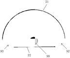
- the first millimeter wave transmitting and receiving antenna array 21 and the second millimeter wave transmitting and receiving antenna array 22 may each have a circular arc shape.
- the first guiding device 31 and the second guiding device 32 may be separate guiding devices, such as separate transmission cables, rails, etc., or may be formed by two different portions of an integral transmission cable, in the latter In this case, during the scanning process, the first millimeter wave transmitting and receiving antenna array 21 and the second millimeter wave transmitting and receiving antenna array 22 will only be able to move in the reverse direction, but it is advantageous to simplify the design of the driving device 40. Similar to the foregoing embodiments, the first guiding device 31 and the second guiding device 32 can be driven by a driving device such as a driving wheel. Accordingly, it may also include a structure such as the data processing device 70, the display device 80, and the control device 71 as described above. With the structure shown in FIG. 2, it is also possible to achieve rapid passage and detection of the object to be tested, and it is possible to perform scanning for most of the circumferential side of the object to be tested (excluding the portion facing the inlet 91 and the outlet 92).
- the transmission cable can also provide certain constraints for the scanning motion of the first millimeter wave transceiver antenna array 21 and the second millimeter wave transceiver antenna array 22 while implementing the transmission.
- the first The one millimeter wave transceiver antenna array 21 and the second millimeter wave transceiver antenna array 22 can only move in the reverse direction at an equal rate.
- first millimeter wave transmit and receive antenna array 21 and the second millimeter wave transmit and receive antenna array 22 may also be combined to form a complete envelope of the object 90 to be measured to achieve a complete scan of all sides of the object 90 to be tested.
- the circular-shaped millimeter wave transmitting and receiving antenna array 20 in the example of FIG. 1 can be replaced by two semicircular annular millimeter wave transmitting and receiving antenna arrays.
- FIG. 3 shows a millimeter wave three-dimensional holographic scanning imaging apparatus 100" according to another embodiment.
- the millimeter wave three-dimensional holographic scanning imaging apparatus 100 similar to the millimeter wave three-dimensional holographic scanning imaging apparatus 100' shown in FIG.
- a first millimeter wave transmitting and receiving antenna array 21, a second millimeter wave transmitting and receiving antenna array 22, a first guiding device 31, a second guiding device 32, a driving device 40, and the like are also provided.
- the first millimeter wave transmitting and receiving antenna array 21 has a circular arc shape
- the second millimeter wave transmitting and receiving antenna array 22 has a linear shape.
- the housing 50 has a semi-cylindrical shape.
- the inlet 92 and the outlet 93 may be disposed on the same side of the detection area 91.
- the object to be tested may enter or exit the millimeter wave three-dimensional holographic scanning imaging apparatus 100" from the inlet 92 by means of the revolving door 55.
- the revolving door 55 may have a first rotational position and a second rotational position, In a rotational position, the revolving door 55 closes the inlet 92 and the outlet 93, and in the second rotational position, the revolving door 55 opens the inlet 92 and the outlet 93, the revolving door 55
- the side of the second millimeter wave transmitting and receiving antenna array 22 of the millimeter wave three-dimensional holographic scanning imaging apparatus 100" is disposed.
- Figure 3 shows the position where the revolving door 55 is closed, i.e., the first rotational position. While the revolving door 55 is rotated 90 degrees about the axis of rotation 56 from the first rotational position, for example, the inlet 92 and the outlet 93 can be opened to reach the second rotational position.
- the second millimeter wave transceiving antenna array 22 can be arranged to rotate with the revolving door 55.
- the second millimeter wave transmitting and receiving antenna array 22 may also be hidden in the housing 50 at a position above or below the revolving door 55 when the revolving door 55 is rotated, thereby avoiding obstructing the rotation of the revolving door 55.
- the inlet 92, the outlet 93 and the arc-shaped first millimeter wave transmitting and receiving antenna array 21 and the linear second millimeter wave transmitting and receiving antenna array 22 may adopt various arrangements, for example, as shown in FIGS. An exemplary arrangement.
- the arc-shaped first millimeter wave transmitting and receiving antenna array 21 and the linear second millimeter wave transmitting and receiving antenna array 22 are combined to form a closed arrangement, so that the inlet 92 and the outlet 93 need to be opened by the revolving door 55. And closed. In this manner, the scanning operation is well sealed and the millimeter wave three-dimensional holographic scanning imaging apparatus 100" can be designed to be more compact to further reduce the footprint.
- the arc-shaped first millimeter wave transmitting and receiving antenna array 21 and the linear second millimeter wave transmitting and receiving antenna array 22 are not combined to form a closed arrangement, but on both sides of the second millimeter wave transmitting and receiving antenna array 22.
- the inlet 92 and the outlet 93 are left. This approach may require a large footprint, but the use of the revolving door 55 can be avoided and omnidirectional scanning of the object 90 to be tested can still be achieved.
- the pitch of the first millimeter wave transmitting and receiving antenna array 21 and the second millimeter wave transmitting and receiving antenna array 22 is further enlarged, the first millimeter wave transmitting and receiving antenna array 21 in the arc shape and the second millimeter in the linear shape.
- the inlet 92 and the outlet 93 left between the wave transmitting and receiving antenna arrays 22 are open at a larger angle, which makes the entry and exit of the object to be tested 90 more convenient, and can enter and exit the millimeter wave three-dimensional holographic scanning imaging device 100 along a straight path. There is no need to turn, but this mode may result in a portion of the object 90 to be tested (e.g., the portion opposite the inlet 92 and the outlet 93) that cannot be scanned.
- the revolving door 55 described above may also employ a double wall structure similar to the first door device 51 and the second door device 52 to accommodate the second millimeter wave transceiver antenna array 22 between the double walls during scanning. .
- the antenna array 21 and the second millimeter wave transceiver antenna array 22 are not in a position facing each other most of the time to reduce interference between the first millimeter wave transceiver antenna array 21 and the second millimeter wave transceiver antenna array 22. This is not essential.
- the first millimeter wave transceiver antenna array 21 and the second millimeter wave transceiver antenna array 22 may also use the same scanning direction for synchronous scanning.
- the first millimeter wave transceiver antenna array 21 and the second millimeter wave transceiver antenna array 22 may also be scanned at different speeds (eg, different sides or different portions of the object to be tested may need to be different) In the case of a fine degree of scanning, this can balance the accuracy and efficiency of the detection.
- the speed of the millimeter wave transceiver antenna array 20, the first millimeter wave transceiver antenna array 21, and the second millimeter wave transceiver antenna array 22 in the scan may be constant or variable, and the latter may implement variable speed scanning. To provide more flexibility for inspection work.
- the at least one millimeter wave transceiving antenna array may be provided with a column of transmitting antennas and a column of receiving antennas arranged offset from each other.
- the column of receiving antennas may be arranged in parallel with the column of transmitting antennas but offset by a half antenna size in the horizontal direction.
- the millimeter wave transceiver system adopts a step frequency continuous wave scanning method, and the frequency scanning range can be 24-30 GHz or 27-33 GHz, and the frequency scanning points are determined by the maximum imaging distance.
- the millimeter wave transmitting and receiving antenna array In the scanning process of the millimeter wave transmitting and receiving antenna array, as an example, when all the transceiver units at a certain height have been operated, the millimeter wave transmitting and receiving antenna array is moved to the next vertical position for the horizontal direction fast scanning as described above. Since the scanning speed of a full row in the horizontal direction is very fast, the scanning antenna array can continuously move at a relatively high speed in the vertical direction.
- the above motion can be achieved by using a drive motor to drive the drive wheel or a drive shaft connected to the drive wheel to rotate and connect the antenna array through a guiding device.
- the two rows of antenna arrays respectively move the distance of the vertical height of the entire device, one scan ends. At this time, the object to be tested can leave the detection area directly from the exit 93, that is, the inspection is completed.
- a millimeter wave source in the operation of a millimeter wave transceiver and a millimeter wave transceiver antenna array, can generate two millimeter wave signals, one is used as a transmission signal, and millimeter waves are emitted through an amplifier and a transmitting antenna; the other is used as a reference.
- the signal is mixed with the millimeter wave signal received by the receiving antenna, and the millimeter wave holographic data is obtained by I/Q demodulation.
- each millimeter wave transceiver antenna array (such as a first millimeter wave transceiver antenna array and a second millimeter wave transceiver antenna array) may employ the same millimeter wave scanning frequency.
- the millimeter wave signal transmitted and received by the first millimeter wave transceiver antenna array and the second millimeter can adopt different frequencies.
- the first millimeter wave transceiver antenna array and the second millimeter wave transceiver antenna array are in the whole process of scanning the object to be measured together with the first millimeter wave transceiver antenna array and the second millimeter wave transceiver antenna array
- the time at which the millimeter wave is emitted is different, that is, the millimeter wave is not emitted at the same time. This can also weaken or avoid signal interference between the first millimeter wave transceiver antenna array and the second millimeter wave transceiver antenna array.
- the millimeter wave three-dimensional holographic scanning imaging apparatus 100, 100', 100" can reduce the footprint of the millimeter wave inspection system and improve the inspection efficiency.
Landscapes
- Engineering & Computer Science (AREA)
- Remote Sensing (AREA)
- Radar, Positioning & Navigation (AREA)
- Physics & Mathematics (AREA)
- Computer Networks & Wireless Communication (AREA)
- General Physics & Mathematics (AREA)
- Electromagnetism (AREA)
- Radar Systems Or Details Thereof (AREA)
Abstract
一种毫米波三维全息扫描成像设备(100),其包括:至少一个毫米波收发机(10)以及与至少一个毫米波收发机(10)对应地电连接、分别用于发送和接收至少一个毫米波信号的至少一个毫米波收发天线阵列(20);至少一个引导装置(30),至少一个毫米波收发天线阵列(20)分别对应连接至至少一个引导装置(30)从而能够随至少一个引导装置(30)移动以对待测对象(90)的周侧进行扫描,至少一个毫米波收发天线阵列(20)的延伸方向分别与至少一个引导装置(30)垂直;驱动装置(40),用于驱动至少一个引导装置(30)移动以带动至少一个毫米波收发天线阵列(20)以沿直线形轨迹进行扫描;和壳体(50),包围待测对象(90)在检测时所处的检测区域(91),所述壳体(50)形成有供待测对象(90)进入检测区域(91)的入口(92)和供待测对象(90)离开检测区域(91)的出口(93)。
Description
交叉引用
本申请要求于2015年12月28日递交中国专利局的、申请号为201511001144.X的中国专利申请的权益,该申请的全部内容以引用方式并入本文。
本发明涉及安检技术领域,尤其涉及一种毫米波三维全息扫描成像设备。
面对日益严峻的公共安全形势,实现快速有效的人体安全检查开始成为机场、地铁站等人流密集场所亟待解决的问题。目前机场的人体安检主要依靠安检员手持金属探测器对乘客进行全身扫描,该方案只对金属物品有效并且无法对隐私部位进行检查。人体安检设备主要包含X射线背散射人体成像设备和毫米波人体成像设备。X射线背散射人体成像设备利用X射线入射到人体表面散射回来的信号进行成像,由于X射线具有致电离性,其在安全性方面易受到公众质疑。毫米波人体成像设备主要包含主动式和被动式两种。主动毫米波成像的图像质量明显优于被动式成像,良好的成像效果保证了对违禁品的高识别率,因此主动式毫米波人体安检设备已经逐渐成为人体安检设备的主流发展方向。而主动式毫米波成像技术又以全息成像技术为主。
运用于人体安检的主动式毫米波三维全息成像技术中,柱面扫描成像技术运用较为广泛,但其设备占地面积大且难以对待测对象的四周进行完整的成像。
发明内容
本发明的目的是提供一种毫米波三维全息扫描成像设备,其能够快速、高效地实现对待测对象(如人体或物品)的各个侧面进行毫米波三维全息扫描成像。
本发明的实施例提供了一种毫米波三维全息扫描成像设备,包括:
至少一个毫米波收发机以及与所述至少一个毫米波收发机对应地电连接的至少一个毫米波收发天线阵列,所述至少一个毫米波收发天线阵列分别用于发送和接收至少一个毫米波信号;
至少一个引导装置,所述至少一个毫米波收发天线阵列分别对应连接至所述至少一个引导装置从而能够随所述至少一个引导装置移动以对待测对象的周侧进行扫描,所述至少一个毫米波收发天线阵列的延伸方向分别与所述至少一个引导装置垂直;
驱动装置,用于驱动所述至少一个引导装置移动以带动所述至少一个毫米波收发天线阵列以沿直线形轨迹进行扫描;和
壳体,所述壳体包围待测对象在检测时所处的检测区域,所述壳体形成有供待测对象进入检测区域的入口和供待测对象离开检测区域的出口。
在一实施例中,所述至少一个毫米波收发天线阵列的扫描方向均为竖直方向,且所述至少一个毫米波收发天线阵列均沿着水平方向延伸。
在一实施例中,所述至少一个毫米波收发天线阵列包括一个圆环形状的毫米波收发天线阵列。
在一实施例中,所述入口和所述出口分别位于所述检测区域的两侧。
在一实施例中,所述毫米波三维全息扫描成像设备还包括:
第一门装置,设置于所述入口处;和
第二门装置,设置于所述出口处,
其中,所述第一门装置和第二门装置配置成在所述至少一个毫米波收发天线阵列进行扫描时关闭而在所述至少一个毫米波收发天线阵列进行扫描之前或之后打开。
在一实施例中,所述第一门装置和第二门装置中的每个具有第一壁和第二壁,所述毫米波收发天线阵列中的至少一个能够从所述第一壁和第二壁之间扫描通过。
在一实施例中,所述第一壁相对于第二壁更靠近所述检测区域,所述第一壁对于所述毫米波信号至少是部分透明的。
在一实施例中,所述至少一个毫米波收发天线阵列包括第一毫米波收发天线阵列和第二毫米波收发天线阵列,所述第一毫米波收发天线阵列用于发送和接收第一毫米波信号,所述第二毫米波收发天线阵列用于发送和接收第二毫米波信号;
所述至少一个引导装置包括第一引导装置和第二引导装置,所述第一毫米波收发天线阵列连接至所述第一引导装置从而能够随所述第一引导装置以第一扫描轨迹移动以对待测对象的第一侧进行扫描,所述第二毫米波收发天线阵列连接至所述第二引导装置从而能够随所述第二引导装置以第二扫描轨迹移动以对所述待测对象的第二侧进行扫描。
在一实施例中,所述第一毫米波收发天线阵列和所述第二毫米波收发天线阵列组合形成对待测对象的完整包围。
在一实施例中,所述第一毫米波收发天线阵列和所述第二毫米波收发天线阵列均具有圆弧形状。
在一实施例中,所述入口和所述出口分别位于所述检测区域的两侧。
在一实施例中,所述第一毫米波收发天线阵列具有圆弧形状,所述第二毫米波收发天线阵列具有直线形状。
在一实施例中,所述入口和所述出口设置在所述检测区域的同一侧。
在一实施例中,所述毫米波三维全息扫描成像设备还包括旋转门,所述旋转门具有第一旋转位置和第二旋转位置,在所述第一旋转位置,所述旋转门关闭所述入口和所述出口,而在所述第二旋转位置,所述旋转门打开所述入口和所述出口,所述旋转门设置在毫米波三维全息扫描成像设备的第二毫米波收发天线阵列所在的一侧。
在一实施例中,所述入口和所述出口均位于所述第一毫米波收发天线阵列和所述第二毫米波收发天线阵列之间。
在一实施例中,所述驱动装置包括驱动轮,所述引导装置包括与所述驱动轮啮合的传动带索。
本发明的上述至少一个实施例能够通过至少一个毫米波收发天线阵列同时对待测对象的周侧进行扫描且通过合理地设置入口和出口而提高检测效率和减小设备体积。
图1示出根据本发明的一实施例的毫米波三维全息扫描成像设备的结构示意图;
图1a示出根据本发明的一实施例的毫米波三维全息扫描成像设备中的第一门装置或第二门装置的结构示意图;
图2示出根据本发明的另一实施例的毫米波三维全息扫描成像设备的示意图;
图3示出根据本发明的又一实施例的毫米波三维全息扫描成像设备的示意图;以及
图4-6分别示出根据本发明的实施例的毫米波三维全息扫描成像设备中毫米波收发天线阵列与入口和出口的布置方式的多个示例的示意性俯视图。
下面通过实施例,并结合附图,对本发明的技术方案作进一步具体的说明。在说明书中,相同或相似的附图标号表示相同或相似的部件。下述参照附图对本发明实施方式的说明旨在对本发明的总体发明构思进行解释,而不应当理解为对本发明的一种限制。
根据本发明的总体构思,提供一种毫米波三维全息扫描成像设备,包括:至少一个毫米波收发机以及与所述至少一个毫米波收发机对应地电连接的至少一个毫米波收发天线阵列,所述至少一个毫米波收发天线阵列分别用于发送和接收至少一个毫米波信号;至少一个引导装置,所述至少一个毫米波收发天线阵列分别对应连接至所述至少一个引导装置从而能够随所述至少一个引导装置移动以对待测对象的周侧进行扫描,所述至少一个毫米波收发天线阵列的延伸方向分别与所述至少一个引导装置垂直;驱动装置,用于驱动所述至少一个引导装置移动以带动所述至少一个毫米波收发天线阵列以沿直线形轨迹进行扫描;和壳体,所述壳体包围待测对象在检测时所处的检测
区域,所述壳体形成有供待测对象进入检测区域的入口和供待测对象离开检测区域的出口。
另外,在下面的详细描述中,为便于解释,阐述了许多具体的细节以提供对本披露实施例的全面理解。然而明显地,一个或更多个实施例在没有这些具体细节的情况下也可以被实施。
图1示意性地示出根据本发明的一实施例的毫米波三维全息扫描成像设备100。该毫米波三维全息扫描成像设备100可以包括:毫米波收发机10以及与所述毫米波收发机10对应地电连接的毫米波收发天线阵列20,所述毫米波收发天线阵列20用于发送和接收毫米波信号;引导装置30,毫米波收发天线阵列20连接至引导装置30从而能够随所述引导装置30移动以对待测对象90的周侧进行扫描,毫米波收发天线阵列20的延伸方向与引导装置30垂直;驱动装置40(例如驱动轮及其电机等),用于驱动引导装置30移动以带动毫米波收发天线阵列20以沿直线形轨迹进行扫描;和壳体50,所述壳体50包围待测对象90在检测时所处的检测区域91,所述壳体50形成有供待测对象90进入检测区域91的入口92和供待测对象90离开检测区域91的出口93。作为示例,壳体50可以具有圆筒形状。作为示例,毫米波收发天线阵列20可以位于壳体50内侧、外侧或壳体50中。
根据本发明的实施例的毫米波三维全息扫描成像设备采用了具有独立的入口92和出口93的结构,待测对象(例如人员或物品)可以方便地在检查之前从入口92进入,而在检查之后从出口93走出。这与仅具有一个出入口的传统检查设备相比,待测对象无需转身就可以进入和离开检测区域,提高了检查效率。这对于机场、车站等人流密集的场所的安全检查尤其有利。
在一示例中,如图1所示,毫米波收发天线阵列20的扫描方向为竖直方向,且毫米波收发天线阵列20沿着水平方向延伸。这种设置有助于方便地实现对于待测对象周侧的扫描。在图1的示例中,毫米波收发天线阵列20具有圆环形状。该圆环形状的毫米波收发天线阵列20完整地围绕待测对象,只需要进行一次从上至下(或从下至上)的扫描就可以完成对于待测对象的所有侧面的毫米波数据进行采集,从而实现全视角的毫米波全息成像。这种方式操作简单,操控便利。然而,本领域技术人员应当理解,虽然在上述示例中采用了一个圆环形状的毫米波收发天线阵列20,但是本发明的实施例不限于此,也可以使用更多个毫米波收发天线阵列20来实现扫描,例如可以将该圆环形状的毫米波收发天线阵列20在圆周方向上分成多个独立的圆弧形状的毫米波收发天线阵列20,同样可以完成对待测对象的扫描。采用多个毫米波收发天线阵列20,可以减轻单个毫米波收发天线阵列20的重量,提高操作的灵活性。
作为示例,入口92和出口93分别位于所述检测区域91的两侧,如图1-2所示。这有助于提高待测对象通过检测区域91的效率,尤其是在待测对象需要排队检测时。
在一示例中,毫米波三维全息扫描成像设备100还可以包括:设置于入口92处的第一门装置51和设置于出口93处的第二门装置52。所述第一门装置51和第二门装置52配置成在所述毫米波收发天线阵列20进行扫描时关闭而在毫米波收发天线阵列20进行扫描之前或之后打开。第一门装置51和第二门装置52能够在毫米波收发天线阵列20进行扫描时为检测区域91提供一个封闭的环境。对于毫米波收发天线阵列20在扫描过程中经过入口92和出口93位置的情况,第一门装置51和第二门装置52可以防止毫米波收发天线阵列20在扫描过程中暴露给待测对象90以避免发生危险或对待测对象90产生不利影响。而在扫描结束后,毫米波收发天线阵列20可以隐藏于壳体50的顶端或底端,而不妨碍待测对象90从入口92或出口93通过。
作为示例,第一门装置51和第二门装置52中的每个可以具有第一壁53和第二壁54,所述毫米波收发天线阵列20能够从所述第一壁53和第二壁54之间扫描通过。这可以避免毫米波收发天线阵列20暴露给待测对象或毫米波三维全息扫描成像设备外部的人员,以避免意外。类似地,壳体50也可以采用与第一门装置51和第二门装置52类似的双层壁结构,以将毫米波收发天线阵列20容纳于双层壁之间。
在一示例中,第一壁53相对于第二壁54更靠近所述检测区域91,所述第一壁53对于毫米波信号至少是部分透明的,例如是完全透明的。这可以保证毫米波收发天线阵列20对于毫米波信号的顺利收发。作为示例,第二壁54可以对于毫米波信号具有屏蔽作用,以防止毫米波信号对于周围环境产生干扰。作为示例,所述第一门装置51和第二门装置52可以是圆弧形的自动门。
在一示例中,该毫米波三维全息扫描成像设备100还可以包括数据处理装置70。数据处理装置70与毫米波收发机无线连接或有线连接以接收来自毫米波收发机的对于待测对象的各个侧面的扫描数据并生成毫米波全息图像。该毫米波三维全息扫描成像设备100还可以包括显示装置80。显示装置80与数据处理装置70相连接,用于接收和显示来自数据处理装置70的毫米波全息图像。
在一示例中,数据处理装置70可以用于控制驱动装置40以驱动毫米波收发天线阵列20运动。在另一示例中,毫米波三维全息扫描成像设备100也可以包括与所述数据处理装置70相独立的控制装置71。
作为示例,驱动装置40可以包括驱动轮41-42,其可以在驱动轴和驱动电机的驱动下旋转。还可以根据需要设置一些从动轮43、44。虽然图1中示出了两个驱动轮41-42和两个从动轮43、44,但在本发明的实施例中,驱动轮和从动轮的数量不限于此,也可以采用一个、两个、三个或多于四个驱动轮或从动轮。在采用多个驱动轮的情况下,这些驱动轮可以独立地工作,也可以一起协作。
作为示例,所述引导装置30可以包括与所述驱动轮41-42啮合的传动带索,例如皮带、缆索等本领域已知的能够用于实现上述传动功能的部件。
作为示例,所述毫米波收发天线阵列20可以通过固定装置35、36固定于引导装置30。该固定装置35、36可以包括滑座、卡件等等。
图2示出根据另一实施例的毫米波三维全息扫描成像设备100’。在该毫米波三维全息扫描成像设备100’中,设有第一毫米波收发天线阵列21和第二毫米波收发天线阵列22,所述第一毫米波收发天线阵列21用于发送和接收第一毫米波信号,所述第二毫米波收发天线阵列22用于发送和接收第二毫米波信号。相应地,该毫米波三维全息扫描成像设备100’还设有第一引导装置31和第二引导装置32,所述第一毫米波收发天线阵列21连接至所述第一引导装置31从而能够随所述第一引导装置31以第一扫描轨迹移动以对待测对象90的第一侧进行扫描,所述第二毫米波收发天线阵列22连接至所述第二引导装置32从而能够随所述第二引导装置32以第二扫描轨迹移动以对所述待测对象90的第二侧进行扫描。作为示例,还可以设有与第一毫米波收发天线阵列21和第二毫米波收发天线阵列22分别对应的第一毫米波收发机11和第二毫米波收发机12。
在图2的示例中,入口91和出口92分别位于检测区域91的两侧第一毫米波收发天线阵列21和第二毫米波收发天线阵列22可以相对地布置,以便于避开入口91和出口92。在这种情况下,可以不在入口91和出口92处设置门装置。为了在对待测对象的扫描中获得尽可能大的扫描面积,第一毫米波收发天线阵列21和所述第二毫米波收发天线阵列22可以均具有圆弧形状。第一引导装置31和第二引导装置32可以是各自独立的引导装置,例如各自独立的传动带索、导轨等等,也可以由一个整体的传动带索的两个不同的部分形成,在后者的情况下,在扫描过程中,第一毫米波收发天线阵列21和第二毫米波收发天线阵列22将只能反向移动,但有利于简化驱动装置40的设计。与前述的实施例相似,第一引导装置31和第二引导装置32可以在诸如驱动轮等驱动装置来驱动。相应地,其也可以包括如前所述的数据处理装置70、显示装置80以及控制装置71等结构。采用图2所示的结构,也可以实现待测对象的快速通过和检测,且可以实现对于待测对象的周侧的大部分(除去面向入口91和出口92的部分)进行扫描。
在一示例中,传动带索在实现传动的同时,也可以为所述第一毫米波收发天线阵列21和第二毫米波收发天线阵列22的扫描运动提供一定的约束,例如,可以使所述第一毫米波收发天线阵列21和第二毫米波收发天线阵列22只能以相等的速率沿反向移动。
在另一示例中,第一毫米波收发天线阵列21和第二毫米波收发天线阵列22也可以组合形成对待测对象90的完整包围以实现对于待测对象90所有侧面的完整扫描。例如,可以将图1的示例中的圆环形状的毫米波收发天线阵列20由两个半圆环形的毫米波收发天线阵列替代。
图3示出根据另一实施例的毫米波三维全息扫描成像设备100”。在该毫米波三维全息扫描成像设备100”中,与如图2所示的毫米波三维全息扫描成像设备100’类似,也设有第一毫米波收发天线阵列21、第二毫米波收发天线阵列22、第一引导装置31、第二引导装置32、驱动装置40等。然而,在图3的示例中,第一毫米波收发天线阵列21具有圆弧形状,第二毫米波收发天线阵列22具有直线形状。相应地,如图3所示,壳体50具有半圆筒形状。
作为示例,入口92和出口93可以设置在检测区域91的同一侧。而待测对象可以借助于旋转门55从入口92进入或从出口93离开该毫米波三维全息扫描成像设备100”。该旋转门55可以具有第一旋转位置和第二旋转位置,在所述第一旋转位置,所述旋转门55关闭所述入口92和所述出口93,而在所述第二旋转位置,所述旋转门55打开所述入口92和所述出口93,所述旋转门55设置在毫米波三维全息扫描成像设备100”的第二毫米波收发天线阵列22所在的一侧。图3示出的是旋转门55关闭的位置,即第一旋转位置。而旋转门55例如从该第一旋转位置围绕旋转轴线56旋转90度,就可以打开入口92和出口93,而到达第二旋转位置。在一示例中,第二毫米波收发天线阵列22可以设置成与旋转门55一起旋转。而替代地,第二毫米波收发天线阵列22也可以在旋转门55旋转时隐藏于壳体50中位于旋转门55上方或下方的位置处,从而避免妨碍旋转门55的旋转。
对于上述示例,入口92、出口93与圆弧形状的第一毫米波收发天线阵列21和直线形状的第二毫米波收发天线阵列22可以采用多种布置方式,例如如图4-图6所示的示例性布置方式。
在图4的示例中,圆弧形状的第一毫米波收发天线阵列21和直线形状的第二毫米波收发天线阵列22组合形成封闭布置,于是,入口92和出口93需要通过旋转门55来打开和封闭。采用这种方式,扫描操作的封闭性好而且可以将毫米波三维全息扫描成像设备100”设计得更为紧凑以进一步减小占地面积。
在图5的示例中,圆弧形状的第一毫米波收发天线阵列21和直线形状的第二毫米波收发天线阵列22没有组合形成封闭布置,而是在第二毫米波收发天线阵列22的两边留出入口92和出口93。这种方式可能需要较大的占地面积,但是可以避免旋转门55的使用且仍然可以实现对待测对象90的全方位扫描。
在图6的示例中,第一毫米波收发天线阵列21和第二毫米波收发天线阵列22的间距进一步拉大,在圆弧形状的第一毫米波收发天线阵列21和直线形状的第二毫米波收发天线阵列22之间留有的入口92和出口93敞开的角度更大,这种方式可以使得待测对象90的进出更为方便,可以沿直线路径进出毫米波三维全息扫描成像设备100”而不需要转弯,但这种模式可能导致待测对象90的一部分(例如与入口92和出口93相对的部分)不能被扫描到。
作为示例,上述旋转门55也可以采用与第一门装置51和第二门装置52相似的双层壁结构以在扫描进行过程中将第二毫米波收发天线阵列22容纳在双层壁之间。
对于设置有第一毫米波收发天线阵列21和第二毫米波收发天线阵列22的毫米波三维全息扫描成像设备100’、100”,作为示例,其可以设置成在扫描过程中第一毫米波收发天线阵列21和第二毫米波收发天线阵列22在大部分时间不处于相互正对的位置,以减小第一毫米波收发天线阵列21和第二毫米波收发天线阵列22之间的干扰。然而这不是必须的,例如,所述第一毫米波收发天线阵列21和第二毫米波收发天线阵列22也可以采用相同的扫描方向来进行同步的扫描。
在另一示例中,第一毫米波收发天线阵列21和第二毫米波收发天线阵列22也可以采用不同的速度进行扫描(例如,在待测对象的不同的侧面或不同的局部可能需要以不同的精细程度进行扫描的情况下),这可以兼顾检测的准确性和效率。作为示例,毫米波收发天线阵列20、第一毫米波收发天线阵列21和第二毫米波收发天线阵列22在扫描中的速度可以是恒定的,也可以是可变的,后者可以实现变速扫描,为检测工作提供更多的灵活性。
作为示例,至少一个毫米波收发天线阵列可以设有彼此错位布置的一列发射天线和一列接收天线。例如,该列接收天线可以与该列发射天线列平行布置但在水平方向上错位半个天线尺寸。在天线阵列工作时,每一时刻只有一个发射天线和其相邻的一个接收天线工作。通过电子开关切换,可以实现水平方向的快速扫描。毫米波收发系统采用步进频率连续波的扫描方法,频率扫描范围可以为24-30GHz或27-33GHz,频率扫描点数由最大成像距离决定。
在毫米波收发天线阵列的扫描过程中,作为示例,当某一高度处的所有收发单元都工作过后,毫米波收发天线阵列移动到下一个竖直位置进行如上所述的水平方向快速扫描。由于在水平方向上一整排扫描的速度非常快,因此扫描天线阵列可以在竖直方向上以较快的速度连续运动。使用驱动电机带动驱动轮或与驱动轮连接的驱动轴转动,并通过引导装置连接天线阵列就可以实现上述运动。当两排天线阵列分别移动了整个装置竖直高度的距离后,一次扫描结束。这时待测对象可以直接从出口93离开检测区域,即完成了该次检查。
作为示例,在毫米波收发机和毫米波收发天线阵列的工作过程中,毫米波源可以产生两路毫米波信号,一路作为发射信号,通过放大器和发射天线对待测对象发出毫米波;另一路作为参考信号,与接收天线接收的毫米波信号混频,通过I/Q解调得到毫米波全息数据。作为示例,各个毫米波收发天线阵列(如第一毫米波收发天线阵列和第二毫米波收发天线阵列)可以采用相同的毫米波扫描频率。
替代地,为了减小第一毫米波收发天线阵列和第二毫米波收发天线阵列之间的信号干扰,在一示例中,第一毫米波收发天线阵列发送和接收的毫米波信号和第二毫米
波收发天线阵列发送和接收的毫米波信号可以采用不同的频率。或者,在另一示例中,在第一毫米波收发天线阵列和第二毫米波收发天线阵列一起对待测对象进行扫描的整个过程中,第一毫米波收发天线阵列和第二毫米波收发天线阵列发射毫米波的时刻不同,即不同时发射毫米波。这也可以削弱或避免第一毫米波收发天线阵列和第二毫米波收发天线阵列之间的信号干扰。
根据本发明的实施例的毫米波三维全息扫描成像设备100、100’、100”,可以减小毫米波检查系统的占地面积和提高检查效率。
虽然结合附图对本发明进行了说明,但是附图中公开的实施例旨在对本发明优选实施方式进行示例性说明,而不能理解为对本发明的一种限制。
虽然本发明总体构思的一些实施例已被显示和说明,本领域普通技术人员将理解,在不背离本总体发明构思的原则和精神的情况下,可对这些实施例做出改变,本发明的范围以权利要求和它们的等同物限定。
Claims (16)
- 一种毫米波三维全息扫描成像设备,包括:至少一个毫米波收发机以及与所述至少一个毫米波收发机对应地电连接的至少一个毫米波收发天线阵列,所述至少一个毫米波收发天线阵列分别用于发送和接收至少一个毫米波信号;至少一个引导装置,所述至少一个毫米波收发天线阵列分别对应连接至所述至少一个引导装置从而能够随所述至少一个引导装置移动以对待测对象的周侧进行扫描,所述至少一个毫米波收发天线阵列的延伸方向分别与所述至少一个引导装置垂直;驱动装置,用于驱动所述至少一个引导装置移动以带动所述至少一个毫米波收发天线阵列以沿直线形轨迹进行扫描;和壳体,所述壳体包围待测对象在检测时所处的检测区域,所述壳体形成有供待测对象进入检测区域的入口和供待测对象离开检测区域的出口。
- 根据权利要求1所述的毫米波三维全息扫描成像设备,其特征在于,所述至少一个毫米波收发天线阵列的扫描方向均为竖直方向,且所述至少一个毫米波收发天线阵列均沿着水平方向延伸。
- 根据权利要求1所述的毫米波三维全息扫描成像设备,其特征在于,所述至少一个毫米波收发天线阵列包括一个圆环形状的毫米波收发天线阵列。
- 根据权利要求3所述的毫米波三维全息扫描成像设备,其特征在于,所述入口和所述出口分别位于所述检测区域的两侧。
- 根据权利要求4所述的毫米波三维全息扫描成像设备,还包括:第一门装置,设置于所述入口处;和第二门装置,设置于所述出口处,其中,所述第一门装置和第二门装置配置成在所述至少一个毫米波收发天线阵列进行扫描时关闭而在所述至少一个毫米波收发天线阵列进行扫描之前或之后打开。
- 根据权利要求5所述的毫米波三维全息扫描成像设备,其特征在于,所述第一门装置和第二门装置中的每个具有第一壁和第二壁,所述毫米波收发天线阵列中的至少一个能够从所述第一壁和第二壁之间扫描通过。
- 根据权利要求6所述的毫米波三维全息扫描成像设备,其特征在于,所述第一壁相对于第二壁更靠近所述检测区域,所述第一壁对于所述毫米波信号至少是部分透明的。
- 根据权利要求1所述的毫米波三维全息扫描成像设备,其特征在于,所述至少一个毫米波收发天线阵列包括第一毫米波收发天线阵列和第二毫米波收发天线阵列,所述第一毫米波收发天线阵列用于发送和接收第一毫米波信号,所述第 二毫米波收发天线阵列用于发送和接收第二毫米波信号;所述至少一个引导装置包括第一引导装置和第二引导装置,所述第一毫米波收发天线阵列连接至所述第一引导装置从而能够随所述第一引导装置以第一扫描轨迹移动以对待测对象的第一侧进行扫描,所述第二毫米波收发天线阵列连接至所述第二引导装置从而能够随所述第二引导装置以第二扫描轨迹移动以对所述待测对象的第二侧进行扫描。
- 根据权利要求8所述的毫米波三维全息扫描成像设备,其特征在于,所述第一毫米波收发天线阵列和所述第二毫米波收发天线阵列组合形成对待测对象的完整包围。
- 根据权利要求8所述的毫米波三维全息扫描成像设备,其特征在于,所述第一毫米波收发天线阵列和所述第二毫米波收发天线阵列均具有圆弧形状。
- 根据权利要求10所述的毫米波三维全息扫描成像设备,其特征在于,所述入口和所述出口分别位于所述检测区域的两侧。
- 根据权利要求8所述的毫米波三维全息扫描成像设备,其特征在于,所述第一毫米波收发天线阵列具有圆弧形状,所述第二毫米波收发天线阵列具有直线形状。
- 根据权利要求12所述的毫米波三维全息扫描成像设备,其特征在于,所述入口和所述出口设置在所述检测区域的同一侧。
- 根据权利要求13所述的毫米波三维全息扫描成像设备,还包括旋转门,所述旋转门具有第一旋转位置和第二旋转位置,在所述第一旋转位置,所述旋转门关闭所述入口和所述出口,而在所述第二旋转位置,所述旋转门打开所述入口和所述出口,所述旋转门设置在毫米波三维全息扫描成像设备的第二毫米波收发天线阵列所在的一侧。
- 根据权利要求13所述的毫米波三维全息扫描成像设备,其特征在于,所述入口和所述出口均位于所述第一毫米波收发天线阵列和所述第二毫米波收发天线阵列之间。
- 根据权利要求1-15中任一项所述的毫米波三维全息扫描成像设备,其特征在于,所述驱动装置包括驱动轮,所述引导装置包括与所述驱动轮啮合的传动带索。
Priority Applications (1)
| Application Number | Priority Date | Filing Date | Title |
|---|---|---|---|
| EP16880608.1A EP3399333B1 (en) | 2015-12-28 | 2016-08-19 | Millimeter wave three-dimensional holographic scanning imaging device |
Applications Claiming Priority (2)
| Application Number | Priority Date | Filing Date | Title |
|---|---|---|---|
| CN201511001144.X | 2015-12-28 | ||
| CN201511001144.XA CN105467386B (zh) | 2015-12-28 | 2015-12-28 | 毫米波三维全息扫描成像设备 |
Publications (1)
| Publication Number | Publication Date |
|---|---|
| WO2017113815A1 true WO2017113815A1 (zh) | 2017-07-06 |
Family
ID=55605287
Family Applications (1)
| Application Number | Title | Priority Date | Filing Date |
|---|---|---|---|
| PCT/CN2016/096000 Ceased WO2017113815A1 (zh) | 2015-12-28 | 2016-08-19 | 毫米波三维全息扫描成像设备 |
Country Status (3)
| Country | Link |
|---|---|
| EP (1) | EP3399333B1 (zh) |
| CN (1) | CN105467386B (zh) |
| WO (1) | WO2017113815A1 (zh) |
Cited By (3)
| Publication number | Priority date | Publication date | Assignee | Title |
|---|---|---|---|---|
| CN109490980A (zh) * | 2018-12-28 | 2019-03-19 | 同方威视技术股份有限公司 | 毫米波安检门 |
| AU2019201619B2 (en) * | 2018-03-09 | 2020-10-08 | Nuctech Company Limited | Extensible Millimeter Wave Security Inspection System, Scanning Unit and Security Inspection Method for Human Body |
| EP3647826A4 (en) * | 2018-08-17 | 2022-03-09 | Tsinghua University | MULTIPLE TRANSMISSION AND MULTIPLE RECEPTION ARRANGEMENTS FOR ACTIVE MILLIMETER WAVE SECURITY INSPECTION IMAGING AND HUMAN BODY SECURITY INSPECTION METHOD AND APPARATUS |
Families Citing this family (15)
| Publication number | Priority date | Publication date | Assignee | Title |
|---|---|---|---|---|
| CN105467386B (zh) * | 2015-12-28 | 2019-01-01 | 同方威视技术股份有限公司 | 毫米波三维全息扫描成像设备 |
| CN105843176A (zh) * | 2016-05-24 | 2016-08-10 | 深圳市无牙太赫兹科技有限公司 | 三维全息成像的伺服旋转扫描系统 |
| EP3483615A1 (en) * | 2017-11-10 | 2019-05-15 | Rohde & Schwarz GmbH & Co. KG | Measuring system and measuring method for over the air measurement of electric field potential |
| CN109061635B (zh) * | 2018-06-08 | 2021-07-06 | 深圳市重投华讯太赫兹科技有限公司 | 旋转扫描系统 |
| CN109375218A (zh) * | 2018-12-04 | 2019-02-22 | 公安部第研究所 | 一种毫米波人体安检设备 |
| CN109633770A (zh) * | 2018-12-28 | 2019-04-16 | 同方威视技术股份有限公司 | 毫米波安检设备及人体或物品检查方法 |
| CN110554383B (zh) * | 2019-09-04 | 2021-04-06 | 中国科学院电子学研究所 | 用于微波频段的mimo环形阵列方位向成像方法及装置 |
| CN110908002B (zh) * | 2019-11-08 | 2021-11-05 | 欧必翼太赫兹科技(北京)有限公司 | 毫米波天线阵列的控制方法及系统 |
| CN111568221A (zh) * | 2020-02-28 | 2020-08-25 | 佛山市云米电器科技有限公司 | 饮水机控制方法、饮水机及计算机可读存储介质 |
| CN111272096B (zh) * | 2020-03-09 | 2021-03-23 | 浙江云特森科技有限公司 | 一种三维扫描装置、安检设备 |
| CN111722211B (zh) * | 2020-06-09 | 2021-11-30 | 上海工物高技术产业发展有限公司 | 人体尺寸测量装置 |
| CN111812740B (zh) * | 2020-06-30 | 2025-05-02 | 北京遥测技术研究所 | 一种旋转扫描安检成像系统 |
| CN112415622B (zh) * | 2020-10-30 | 2024-06-11 | 李世超 | 一种基于弧形阵列的毫米波成像系统 |
| CN112835038A (zh) * | 2020-12-29 | 2021-05-25 | 北京理工大学 | 一种基于折线阵列的成像系统 |
| CN114690262B (zh) * | 2022-03-04 | 2025-06-27 | 杭州睿影科技有限公司 | 扫描成像装置 |
Citations (12)
| Publication number | Priority date | Publication date | Assignee | Title |
|---|---|---|---|---|
| US20030117310A1 (en) * | 2001-12-11 | 2003-06-26 | Nec Corporation | Radar system, method of obtaining image, control method based on image data and monitoring method using milliwaves |
| CN101866018A (zh) * | 2010-05-27 | 2010-10-20 | 中国科学院上海微系统与信息技术研究所 | 一种用于毫米波全息成像安检系统的射频收发前端 |
| CN203385857U (zh) * | 2013-08-15 | 2014-01-08 | 同方威视技术股份有限公司 | 毫米波三维全息扫描成像设备 |
| CN203385856U (zh) * | 2013-08-15 | 2014-01-08 | 同方威视技术股份有限公司 | 毫米波三维全息扫描成像设备 |
| CN203385855U (zh) * | 2013-08-15 | 2014-01-08 | 同方威视技术股份有限公司 | 一种用于人体安全检查的毫米波全息成像设备 |
| CN104375145A (zh) * | 2014-11-07 | 2015-02-25 | 深圳市一体投资控股集团有限公司 | 一种毫米波成像方法及系统 |
| CN104375143A (zh) * | 2013-08-15 | 2015-02-25 | 同方威视技术股份有限公司 | 毫米波三维全息扫描成像设备及人体或物品检查方法 |
| CN104375142A (zh) * | 2013-08-15 | 2015-02-25 | 同方威视技术股份有限公司 | 一种用于人体安全检查的毫米波全息成像设备 |
| CN104375144A (zh) * | 2013-08-15 | 2015-02-25 | 同方威视技术股份有限公司 | 毫米波三维全息扫描成像设备及人体或物品检查方法 |
| CN204228955U (zh) * | 2014-11-07 | 2015-03-25 | 深圳市一体投资控股集团有限公司 | 一种毫米波成像装置 |
| CN105467386A (zh) * | 2015-12-28 | 2016-04-06 | 同方威视技术股份有限公司 | 毫米波三维全息扫描成像设备 |
| CN205263309U (zh) * | 2015-12-28 | 2016-05-25 | 同方威视技术股份有限公司 | 毫米波三维全息扫描成像设备 |
Family Cites Families (3)
| Publication number | Priority date | Publication date | Assignee | Title |
|---|---|---|---|---|
| US6876322B2 (en) * | 2003-06-26 | 2005-04-05 | Battelle Memorial Institute | Concealed object detection |
| US7365672B2 (en) * | 2001-03-16 | 2008-04-29 | Battelle Memorial Institute | Detection of a concealed object |
| CN103698762B (zh) * | 2013-12-30 | 2016-11-23 | 北京无线电计量测试研究所 | 一种虚轴式毫米波人体安检系统 |
-
2015
- 2015-12-28 CN CN201511001144.XA patent/CN105467386B/zh active Active
-
2016
- 2016-08-19 WO PCT/CN2016/096000 patent/WO2017113815A1/zh not_active Ceased
- 2016-08-19 EP EP16880608.1A patent/EP3399333B1/en active Active
Patent Citations (12)
| Publication number | Priority date | Publication date | Assignee | Title |
|---|---|---|---|---|
| US20030117310A1 (en) * | 2001-12-11 | 2003-06-26 | Nec Corporation | Radar system, method of obtaining image, control method based on image data and monitoring method using milliwaves |
| CN101866018A (zh) * | 2010-05-27 | 2010-10-20 | 中国科学院上海微系统与信息技术研究所 | 一种用于毫米波全息成像安检系统的射频收发前端 |
| CN203385857U (zh) * | 2013-08-15 | 2014-01-08 | 同方威视技术股份有限公司 | 毫米波三维全息扫描成像设备 |
| CN203385856U (zh) * | 2013-08-15 | 2014-01-08 | 同方威视技术股份有限公司 | 毫米波三维全息扫描成像设备 |
| CN203385855U (zh) * | 2013-08-15 | 2014-01-08 | 同方威视技术股份有限公司 | 一种用于人体安全检查的毫米波全息成像设备 |
| CN104375143A (zh) * | 2013-08-15 | 2015-02-25 | 同方威视技术股份有限公司 | 毫米波三维全息扫描成像设备及人体或物品检查方法 |
| CN104375142A (zh) * | 2013-08-15 | 2015-02-25 | 同方威视技术股份有限公司 | 一种用于人体安全检查的毫米波全息成像设备 |
| CN104375144A (zh) * | 2013-08-15 | 2015-02-25 | 同方威视技术股份有限公司 | 毫米波三维全息扫描成像设备及人体或物品检查方法 |
| CN104375145A (zh) * | 2014-11-07 | 2015-02-25 | 深圳市一体投资控股集团有限公司 | 一种毫米波成像方法及系统 |
| CN204228955U (zh) * | 2014-11-07 | 2015-03-25 | 深圳市一体投资控股集团有限公司 | 一种毫米波成像装置 |
| CN105467386A (zh) * | 2015-12-28 | 2016-04-06 | 同方威视技术股份有限公司 | 毫米波三维全息扫描成像设备 |
| CN205263309U (zh) * | 2015-12-28 | 2016-05-25 | 同方威视技术股份有限公司 | 毫米波三维全息扫描成像设备 |
Non-Patent Citations (1)
| Title |
|---|
| See also references of EP3399333A4 * |
Cited By (4)
| Publication number | Priority date | Publication date | Assignee | Title |
|---|---|---|---|---|
| AU2019201619B2 (en) * | 2018-03-09 | 2020-10-08 | Nuctech Company Limited | Extensible Millimeter Wave Security Inspection System, Scanning Unit and Security Inspection Method for Human Body |
| US11226429B2 (en) | 2018-03-09 | 2022-01-18 | Nuctech Company Limited | Extensible millimeter wave security inspection system, scanning unit and security inspection method for human body |
| EP3647826A4 (en) * | 2018-08-17 | 2022-03-09 | Tsinghua University | MULTIPLE TRANSMISSION AND MULTIPLE RECEPTION ARRANGEMENTS FOR ACTIVE MILLIMETER WAVE SECURITY INSPECTION IMAGING AND HUMAN BODY SECURITY INSPECTION METHOD AND APPARATUS |
| CN109490980A (zh) * | 2018-12-28 | 2019-03-19 | 同方威视技术股份有限公司 | 毫米波安检门 |
Also Published As
| Publication number | Publication date |
|---|---|
| EP3399333B1 (en) | 2021-10-27 |
| CN105467386A (zh) | 2016-04-06 |
| EP3399333A4 (en) | 2018-12-26 |
| EP3399333A1 (en) | 2018-11-07 |
| CN105467386B (zh) | 2019-01-01 |
Similar Documents
| Publication | Publication Date | Title |
|---|---|---|
| WO2017113815A1 (zh) | 毫米波三维全息扫描成像设备 | |
| EP3396405B1 (en) | Millimeter wave three-dimensional holographic scan imaging apparatus and inspection method for human body or object | |
| RU2583735C2 (ru) | Сканирующее устройство для формирования трехмерного голографического изображения в миллиметровом диапазоне волн и способ обследования человеческого тела или какого-либо предмета с помощью такого устройства | |
| CN104375142B (zh) | 一种用于人体安全检查的毫米波全息成像设备 | |
| US9599705B2 (en) | Millimetre wave three dimensional holographic scan imaging apparatus and method for inspecting a human body or an article | |
| US11662457B2 (en) | Terahertz security inspection robot | |
| US20150048964A1 (en) | Millimeter wave three dimensional holographic scan imaging apparatus and inspecting method thereof | |
| US20190277999A1 (en) | Extensible millimeter wave security inspection system, scanning unit and security inspection method for human body | |
| CN205263309U (zh) | 毫米波三维全息扫描成像设备 | |
| WO2017107284A1 (zh) | 基于毫米波全息三维成像的人体安检系统及方法 | |
| WO2020041161A1 (en) | Pass-through x-ray backscatter personnel scanner | |
| CN109001831A (zh) | 基于平面扫描三维成像的人体安检系统及方法 | |
| CN106918843A (zh) | 一种基于被动式太赫兹成像的视频速度扫描系统 | |
| WO2019237722A1 (zh) | 一种安检设备以及安检系统 | |
| CN205280934U (zh) | 毫米波三维全息扫描成像设备 | |
| CN109633770A (zh) | 毫米波安检设备及人体或物品检查方法 | |
| CN111272096B (zh) | 一种三维扫描装置、安检设备 | |
| CN211086641U (zh) | 一种x射线透射和背散射一体化检测装置 | |
| CN114527516B (zh) | 多通道射线检查设备 | |
| CN114518606B (zh) | 多通道射线检查设备 | |
| CN111352170B (zh) | 一种分段式扫描方法 | |
| CN205786397U (zh) | 检测设备 | |
| CN209132428U (zh) | 一种毫米波人体安检设备 | |
| CN209215261U (zh) | 一种用于x射线透射与背散射一体成像系统的扫描器 | |
| CN209879019U (zh) | 毫米波安检设备 |
Legal Events
| Date | Code | Title | Description |
|---|---|---|---|
| 121 | Ep: the epo has been informed by wipo that ep was designated in this application |
Ref document number: 16880608 Country of ref document: EP Kind code of ref document: A1 |
|
| NENP | Non-entry into the national phase |
Ref country code: DE |