WO2017115411A1 - ステアバイワイヤ方式の電動パワーステアリング装置およびその制御方法 - Google Patents
ステアバイワイヤ方式の電動パワーステアリング装置およびその制御方法 Download PDFInfo
- Publication number
- WO2017115411A1 WO2017115411A1 PCT/JP2015/086498 JP2015086498W WO2017115411A1 WO 2017115411 A1 WO2017115411 A1 WO 2017115411A1 JP 2015086498 W JP2015086498 W JP 2015086498W WO 2017115411 A1 WO2017115411 A1 WO 2017115411A1
- Authority
- WO
- WIPO (PCT)
- Prior art keywords
- motor
- steering
- double
- winding
- steer
- Prior art date
- Legal status (The legal status is an assumption and is not a legal conclusion. Google has not performed a legal analysis and makes no representation as to the accuracy of the status listed.)
- Ceased
Links
Images



Classifications
-
- B—PERFORMING OPERATIONS; TRANSPORTING
- B62—LAND VEHICLES FOR TRAVELLING OTHERWISE THAN ON RAILS
- B62D—MOTOR VEHICLES; TRAILERS
- B62D5/00—Power-assisted or power-driven steering
- B62D5/04—Power-assisted or power-driven steering electrical, e.g. using an electric servo-motor connected to, or forming part of, the steering gear
- B62D5/0457—Power-assisted or power-driven steering electrical, e.g. using an electric servo-motor connected to, or forming part of, the steering gear characterised by control features of the drive means as such
- B62D5/0481—Power-assisted or power-driven steering electrical, e.g. using an electric servo-motor connected to, or forming part of, the steering gear characterised by control features of the drive means as such monitoring the steering system, e.g. failures
- B62D5/0484—Power-assisted or power-driven steering electrical, e.g. using an electric servo-motor connected to, or forming part of, the steering gear characterised by control features of the drive means as such monitoring the steering system, e.g. failures for reaction to failures, e.g. limp home
-
- B—PERFORMING OPERATIONS; TRANSPORTING
- B62—LAND VEHICLES FOR TRAVELLING OTHERWISE THAN ON RAILS
- B62D—MOTOR VEHICLES; TRAILERS
- B62D5/00—Power-assisted or power-driven steering
- B62D5/001—Mechanical components or aspects of steer-by-wire systems, not otherwise provided for in this maingroup
-
- B—PERFORMING OPERATIONS; TRANSPORTING
- B62—LAND VEHICLES FOR TRAVELLING OTHERWISE THAN ON RAILS
- B62D—MOTOR VEHICLES; TRAILERS
- B62D5/00—Power-assisted or power-driven steering
- B62D5/001—Mechanical components or aspects of steer-by-wire systems, not otherwise provided for in this maingroup
- B62D5/003—Backup systems, e.g. for manual steering
-
- B—PERFORMING OPERATIONS; TRANSPORTING
- B62—LAND VEHICLES FOR TRAVELLING OTHERWISE THAN ON RAILS
- B62D—MOTOR VEHICLES; TRAILERS
- B62D5/00—Power-assisted or power-driven steering
- B62D5/001—Mechanical components or aspects of steer-by-wire systems, not otherwise provided for in this maingroup
- B62D5/005—Mechanical components or aspects of steer-by-wire systems, not otherwise provided for in this maingroup means for generating torque on steering wheel or input member, e.g. feedback
- B62D5/006—Mechanical components or aspects of steer-by-wire systems, not otherwise provided for in this maingroup means for generating torque on steering wheel or input member, e.g. feedback power actuated
-
- B—PERFORMING OPERATIONS; TRANSPORTING
- B62—LAND VEHICLES FOR TRAVELLING OTHERWISE THAN ON RAILS
- B62D—MOTOR VEHICLES; TRAILERS
- B62D5/00—Power-assisted or power-driven steering
- B62D5/04—Power-assisted or power-driven steering electrical, e.g. using an electric servo-motor connected to, or forming part of, the steering gear
- B62D5/0403—Power-assisted or power-driven steering electrical, e.g. using an electric servo-motor connected to, or forming part of, the steering gear characterised by constructional features, e.g. common housing for motor and gear box
-
- H—ELECTRICITY
- H02—GENERATION; CONVERSION OR DISTRIBUTION OF ELECTRIC POWER
- H02P—CONTROL OR REGULATION OF ELECTRIC MOTORS, ELECTRIC GENERATORS OR DYNAMO-ELECTRIC CONVERTERS; CONTROLLING TRANSFORMERS, REACTORS OR CHOKE COILS
- H02P25/00—Arrangements or methods for the control of AC motors characterised by the kind of AC motor or by structural details
- H02P25/16—Arrangements or methods for the control of AC motors characterised by the kind of AC motor or by structural details characterised by the circuit arrangement or by the kind of wiring
- H02P25/22—Multiple windings; Windings for more than three phases
-
- H—ELECTRICITY
- H02—GENERATION; CONVERSION OR DISTRIBUTION OF ELECTRIC POWER
- H02P—CONTROL OR REGULATION OF ELECTRIC MOTORS, ELECTRIC GENERATORS OR DYNAMO-ELECTRIC CONVERTERS; CONTROLLING TRANSFORMERS, REACTORS OR CHOKE COILS
- H02P27/00—Arrangements or methods for the control of AC motors characterised by the kind of supply voltage
- H02P27/04—Arrangements or methods for the control of AC motors characterised by the kind of supply voltage using variable-frequency supply voltage, e.g. inverter or converter supply voltage
- H02P27/06—Arrangements or methods for the control of AC motors characterised by the kind of supply voltage using variable-frequency supply voltage, e.g. inverter or converter supply voltage using DC to AC converters or inverters
-
- H—ELECTRICITY
- H02—GENERATION; CONVERSION OR DISTRIBUTION OF ELECTRIC POWER
- H02P—CONTROL OR REGULATION OF ELECTRIC MOTORS, ELECTRIC GENERATORS OR DYNAMO-ELECTRIC CONVERTERS; CONTROLLING TRANSFORMERS, REACTORS OR CHOKE COILS
- H02P29/00—Arrangements for regulating or controlling electric motors, appropriate for both AC and DC motors
- H02P29/02—Providing protection against overload without automatic interruption of supply
- H02P29/024—Detecting a fault condition, e.g. short circuit, locked rotor, open circuit or loss of load
- H02P29/028—Detecting a fault condition, e.g. short circuit, locked rotor, open circuit or loss of load the motor continuing operation despite the fault condition, e.g. eliminating, compensating for or remedying the fault
Definitions
- the present invention relates to a steer-by-wire type electric power steering apparatus and a control method thereof.
- An object of the present invention is to solve the above-described problems and to obtain a steer-by-wire type electric power steering apparatus and a control method thereof that ensure safety without using a backup clutch.
- the present invention relates to a steering input mechanism having a handle that is operated by a driver, a reaction force motor that applies a steering reaction force to the handle, a steering motor that outputs a steering force, and a mechanical input to the steering input mechanism.
- a steering mechanism that steers the steered wheels by the steering force of the steering motor without being connected, and a drive control device that controls the driving of the steering motor and the reaction force motor.
- At least one of the rudder motor and the reaction force motor is a steer-by-wire type of double-winding motor in which each winding is doubled, and each of the doubled windings is individually driven by two inverters. It is in an electric power steering device or the like.
- the safety of the steer-by-wire type electric power steering device can be ensured without using a backup clutch.
- FIG. 1 is a diagram illustrating an overall configuration of a steer-by-wire electric power steering apparatus according to the present invention. It is a block diagram of a control system of a double inverter type three-phase double winding motor in the steer-by-wire type electric power steering device of the present invention. It is a functional block diagram of an example of the microcomputer of the drive control apparatus of FIG. It is a figure which shows an example of a hardware structure of the microcomputer of the drive control apparatus of FIG. FIG. 3 is an operation flowchart showing an example of a control operation when a double inverter type three-phase double winding motor of the microcomputer of the drive control device of FIG. 2 fails. It is a figure which shows the structural example of the motor and drive control apparatus of the electric power steering apparatus of a steer-by-wire system of this invention.
- the safety of the apparatus can be ensured without using a backup clutch. There are few layout restrictions.
- FIG. 1 is a diagram showing the overall configuration of a steer-by-wire type electric power steering apparatus of the present invention.
- a steering shaft 5 is connected to a handle 4 operated by a driver.
- a steering angle sensor 6 that detects the steering angle of the driver and two reaction force motors 7 a and 7 b that are provided together to apply a steering reaction force to the steering of the driver are attached to the steering shaft 5.
- the steering input mechanism 2 is configured by the handle 4, the steering shaft 5, and the steering angle sensor 6.
- Tie rods 10a and 10b connected to the rack shaft 11 are connected to the knuckle arms 9a and 9b of the front wheels 8a and 8b which are steered wheels.
- the movement of the rack shaft 11 is transmitted to the front wheels 8a and 8b through the tie rods 10a and 10b and the knuckle arms 9a and 9b, whereby the front wheels 8a and 8b are steered.
- Steering motors 12 a and 12 b are attached to the rack shaft 11.
- the outputs of the two steered motors 12a and 12b provided side by side serve as power for moving the rack shaft 11.
- the steering mechanism 3 is configured by the knuckle arms 9 a and 9 b, the tie rods 10 a and 10 b, and the rack shaft 11 around the rack shaft 11.
- the steering input mechanism 2 and the steering mechanism 3 are not mechanically connected. Based on an input signal from the steering angle sensor 6 or the like, the drive control device 100 appropriately controls the steering motors 12a and 12b and the reaction force motors 7a and 7b, so that steering according to the operation of the driver is performed. A so-called steer-by-wire type electric power steering apparatus 1 is formed.
- Each of the steered motor 12a, steered motor 12b, reaction force motor 7a, and reaction force motor 7b individually drives two sets of three-phase windings and two sets of three-phase windings. And a double inverter type three-phase double winding motor having two inverters.
- the steered motor 12a, steered motor 12b, reaction force motor 7a, and reaction force motor 7b are configured not to completely lose their functions as a motor even when a failure occurs.
- FIG. 2 is a configuration diagram of a control system of a double inverter type three-phase double winding motor in the steer-by-wire type electric power steering device of the present invention.
- the drive control apparatus 100 includes a control unit 100a configured by, for example, a microcomputer 100aa.
- the microcomputer 100aa of the drive control device 100 is A steering angle signal SA from the steering angle sensor 6; Input drive command IDC from outside, A feedback signal FB from a current detector 100c, which is provided in a three-phase double winding motor (7a, 7b, 12a, 12b) to detect a motor failure and detects a phase current and a drive current; For example, output drive commands ODC1 and ODC2 for driving and controlling the three-phase double winding motor (7a, 7b, 12a, 12b) Output to the drive circuit 210c.
- the steering motor 12a, the steering motor 12b, the reaction force motor 7a, and the reaction force motor 7b each of which is a double inverter type three-phase double winding motor, A three-phase winding 19 of a first system and a three-phase winding 20 of a second system,
- the first FET drive circuit 210ca and the first system inverter circuit 210a constitute one inverter
- the second FET drive circuit 210cb and the second system inverter circuit 210b constitute another inverter.
- Inverter circuits 210a and 210b include a parallel capacitor 203 and a switching circuit 204 that are common to each phase of each inverter circuit between a power supply side terminal connected to a battery 201 that is a power source via a common reactor 202 and the ground.
- Two switching units 205 and a shunt resistor 206 connected in series are connected in series.
- Each switching unit 205 includes a switching element 205a made of, for example, a MOS-FET, and a parasitic diode 205b is provided inside the FET.
- a connection point between the switching units 205 connected in series is connected to each of the three-phase windings 19 and 20.
- a current detector 100 c is provided on a connection line connected to the winding, and a feedback signal FB is output to the drive control device 100.
- the current detector 100c may be provided for each phase, or one current detector 100c may be provided in common for the three phases on the connection line through which all phase currents of the three-phase windings flow.
- the detection of the failure may be configured to use the output of the shunt resistor 206 which is a current detector for current feedback control of the motor without providing the dedicated current detector 100c.
- the first FET drive circuit 210ca and the second FET drive circuit 210cb of the inverter drive circuit 210c are three-phase double winding motors (7a, 7b) according to output drive commands ODC1, ODC2 from the microcomputer 100aa of the drive control device 100. , 12a, 12b) outputs switching signals for ON / OFF control of the switching elements 205a of the switching units 205 of the inverter circuits 210a, 210b.
- connection terminals U1, V1, and W1 of the first system three-phase winding 19 are connected to the first system inverter circuit 210a controlled by the microcomputer 100aa and the first FET drive circuit 210ca.
- connection terminals U2, V2, and W2 of the second system three-phase winding 20 are connected to a second system inverter circuit 210b controlled by the microcomputer 100aa and the second FET drive circuit 210cb.
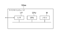
- FIG. 3 shows a functional block diagram of an example of the microcomputer 100aa constituting the control unit 100a of the drive control device 100.
- the microcomputer 100aa includes a failure detection unit 301, a drive command generation unit 302, and a storage unit M.
- the microcomputer 100aa includes an interface I / F for inputting / outputting signals to / from the outside, a program for executing the functions indicated by the functional blocks shown in FIG. 3, and a memory M storing various data necessary for processing. And a CPU that executes a program stored in the memory M.
- FIG. 5 shows an operation flowchart of an example of a control operation by the microcomputer 100aa at the time of failure of the double inverter type three-phase double winding motor, and the operation will be described below.
- a case where a failure occurs in the second phase three-phase winding 20 of the steered motor 12a will be described as an example.
- the failure detection unit 301 of the microcomputer 100aa detects a failure by comparing the value of the feedback signal FB from the current detector 100c with a preset normal region value. For example, when the value of the feedback signal FB from the second phase three-phase winding 20 of the second phase motor of the three-phase double winding motor exceeds or falls below the value in the normal region, the second phase three-phase winding 20 fails.
- step S1 when a command “stop driving the faulty system of the motor if a failure occurs” is set by an external input drive command IDC (step S2), the drive command generation unit 302 sets the second FET drive. An output drive command ODC2 for stopping driving of the circuit 210cd is output. As a result, the drive current of the three-phase winding 20 of the second system becomes 0 (step S3). Therefore, the torque generated by the second system including the second FET drive circuit 210cb and the second system inverter circuit 210b of the steered motor 12a is 0, and the output torque of the entire motor is 2 minutes of the normal time. Although it becomes 1, the function can be continued without losing the function completely.
- a drive command generation unit 302 when a command is set by an external input drive command IDC to “stop driving the fault system of the motor and perform compensation control when a failure occurs” (step S4), a drive command generation unit 302 outputs an output drive command ODC2 for stopping the driving of the second FET drive circuit 210cb, and the drive current of the three-phase winding 20 of the second system is set to zero.
- the drive command generator 302 outputs the output drive command ODC1 so as to increase the drive current of the normal three-phase winding 19 of the first system to twice that of the normal time.
- the torque generated by the first system is doubled (step S5).
- step S6 when a command “compensation control is performed with a co-located motor” is set by an input drive command IDC from the outside (step S6), for example, a normal steered motor co-located with no failure occurring.
- the drive command generator 302 In order to increase the output of 12b by an amount that compensates for the decreased output of the steering motor 12a in which a failure has occurred, the drive command generator 302 generates an inverter for the steering motor 12b in accordance with the drive current detected in the fault system.
- the output drive command ODC1 and the output drive command ODC2 are output to the first FET drive circuit 210ca and the second FET drive circuit 210cb of the drive circuit 210c, respectively.
- step S7 the drive currents of the first system three-phase winding 19 and the second system three-phase winding 20 in the steering motor 12b are increased to compensate for the decreased output of the steering motor 12a (step S7).
- the output of the entire apparatus can be kept unchanged from the normal time.
- the setting condition of the control mode at the time of failure has been determined according to the input drive command IDC from the outside.
- the control at the time of failure stored in the storage unit M, ie, the memory M in advance. You may control according to a form.
- the steer-by-wire type electric power steering device configured as described above can maintain its function even in the event of a motor failure.
- a backup clutch that mechanically connects the input mechanism and the steering mechanism is not required, and it is small, lightweight, low cost, requires fewer assembly steps, and has fewer layout constraints.
- reaction force motors of conventional single inverter type 3 phase single winding motor The reaction force motor of the double inverter type three-phase double winding motor according to the present invention is represented by 7a, 7b, 12 of the conventional single inverter type 3 phase single winding motor steering motor,
- the double inverter type three-phase double-winding motor turning motor according to the present invention is represented by 12a, 12b,
- the drive control device is indicated by 100.
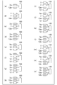
- FIG. (a) shows the structural example by one steering motor and one reaction force motor which consist of "double” steering motor 12a and “double” reaction force motor 7a.
- (b) shows the structural example by one steering motor and two reaction force motors which consist of a “double” steering motor 12a and two “single” reaction force motors 7.
- FIG. (c) is a configuration example of one steering motor and two reaction force motors, each of which includes a “double” steering motor 12a, a “single” reaction force motor 7 and a “double” reaction force motor 7a.
- Show. (d) shows the structural example by one steering motor and two reaction force motors which consist of a "double” steering motor 12a and two “double” reaction force motors 7a and 7b.
- (e) shows a configuration example of two steering motors and one reaction force motor, each including two “single” steering motors 12 and a “double” reaction force motor 7a.
- (f) is composed of two steering motors and two reaction force motors including two “single” steering motors 12, a “double” reaction force motor 7 a and a “single” reaction force motor 7.
- a configuration example is shown.
- (g) shows a configuration example of two steering motors and two reaction force motors including two “single” steering motors 12 and two “double” reaction force motors 7a and 7b.
- (h) is a configuration example of two steering motors and one reaction force motor comprising a “double” steering motor 12a, a “single” steering motor 12 and a “double” reaction force motor 7a. Show.
- (i) is composed of two steering motors and two reaction force motors comprising a “double” steering motor 12a, a “single” steering motor 12 and two “single” reaction force motors 7.
- a configuration example is shown.
- (j) is composed of two steering motors 2 consisting of a "double” steering motor 12a, a “single” steering motor 12, a “double” reaction force motor 7a, and a “single” reaction force motor 7.
- the structural example by one reaction force motor is shown.
- (k) shows two steering motors and two reaction forces comprising a “double” steering motor 12a, a “single” steering motor 12 and two “double” reaction force motors 7a and 7b.
- the structural example by a motor is shown.
- (l) shows a configuration example of two turning motors and one reaction force motor, each including two “double” turning motors 12a and 12b and a “double” reaction force motor 7a.
- (m) shows a configuration example of two steering motors and two reaction force motors, each including two “double” steering motors 12 a and 12 b and two “single” reaction force motors 7. .
- (n) is composed of two “double” steering motors 12a and 12b, a “double” reaction force motor 7a, and a “single” reaction force motor 7, two steering motors and two reaction forces.
- the structural example by a motor is shown.
- (o) is composed of two “double” steering motors 12a, 12b and two “double” reaction force motors 7a, 7b in the above-described embodiment.
- the structural example by a reaction force motor is shown.
- step S6 of FIG. 5 under the control of the microcomputer 100aa, when the command “execution compensation control is performed with the side-by-side motor” is set as the input drive command IDC, for example, there is no side failure.
- control may be performed so as to adjust the drive current of the steering motor 12 of the normal three-phase single winding motor of the conventional single inverter system. The same applies to the case of a reaction force motor.
- a single microcomputer is used as the drive control device.
- one microcomputer may be provided for each system, and the motor is not limited to the three-phase system.
- the present invention can also be applied to an electric power steering apparatus provided with a multiphase motor.
- the present invention is applicable to steer-by-wire electric power steering devices for various types of vehicles.
Landscapes
- Engineering & Computer Science (AREA)
- Chemical & Material Sciences (AREA)
- Combustion & Propulsion (AREA)
- Transportation (AREA)
- Mechanical Engineering (AREA)
- Power Engineering (AREA)
- Power Steering Mechanism (AREA)
- Steering Control In Accordance With Driving Conditions (AREA)
Abstract
バックアップクラッチを用いることなしに安全性を確保したステアバイワイヤ方式の電動パワーステアリング装置を得る。運転者が操作するハンドルを有する操舵入力機構と、前記ハンドルに操舵反力を付与する反力モータと、転舵力を出力する転舵モータと、前記操舵入力機構に機械的に接続されずに、前記転舵モータの転舵力により操向輪を転舵する転舵機構と、前記転舵モータおよび前記反力モータの駆動制御を行う駆動制御装置と、を備え、前記転舵モータおよび前記反力モータの少なくとも1つが、各巻線が二重化され、二重化された前記巻線のそれぞれを2つのインバータで個別に駆動するダブルインバータ方式のダブル巻線モータからなる。
Description
この発明は、ステア・バイ・ワイヤ方式の電動パワーステアリング装置およびその制御方法に関する。
従来のステア・バイ・ワイヤ方式の電動パワーステアリング装置においては、装置の故障時に、操舵入力機構のハンドルと、操向輪を転舵する転舵機構を、機械的に連結するためのバックアップクラッチが設けられていた(例えば、特許文献1参照)。
上記特許文献1に示した、従来のステア・バイ・ワイヤ方式の電動パワーステアリング装置においては、装置の故障時に、操舵入力機構のハンドルと、操向輪を転舵する転舵機構を、機械的に連結するためのバックアップクラッチが設けられている。このため、装置が大型化する等の課題があった。
この発明は、上記の課題を解消し、バックアップクラッチを用いることなしに安全性を確保したステアバイワイヤ方式の電動パワーステアリング装置およびその制御方法を得ることを目的としている。
この発明は、運転者が操作するハンドルを有する操舵入力機構と、前記ハンドルに操舵反力を付与する反力モータと、転舵力を出力する転舵モータと、前記操舵入力機構に機械的に接続されずに、前記転舵モータの転舵力により操向輪を転舵する転舵機構と、前記転舵モータおよび前記反力モータの駆動制御を行う駆動制御装置と、を備え、前記転舵モータおよび前記反力モータの少なくとも1つが、各巻線が二重化され、二重化された前記巻線のそれぞれを2つのインバータで個別に駆動するダブルインバータ方式のダブル巻線モータからなる、ステアバイワイヤ方式の電動パワーステアリング装置等にある。
この発明によれば、バックアップクラッチを用いることなしにステアバイワイヤ方式の電動パワーステアリング装置の安全性を確保できる。
この発明によるステア・バイ・ワイヤ方式の電動パワーステアリング装置およびその制御方法においては、バックアップクラッチを用いることなしに装置の安全性を確保できるため、例えば、小型、軽量、低コストで組立工数が少なく、レイアウトの制約が少ない。
以下、この発明によるステア・バイ・ワイヤ方式の電動パワーステアリング装置およびその制御方法を実施の形態に従って図面を用いて説明する。なお、各図において、同一もしくは相当部分は同一符号で示し、また重複する説明は省略する。
実施の形態1.
図1はこの発明のステア・バイ・ワイヤ方式の電動パワーステアリング装置の全体の構成を示す図である。
図1はこの発明のステア・バイ・ワイヤ方式の電動パワーステアリング装置の全体の構成を示す図である。
図1において、運転者が操作するハンドル4にはステアリングシャフト5が連結されている。ステアリングシャフト5には運転者の操舵角を検知する操舵角センサ6と、運転者の操舵に対し操舵反力を付与する併設された2つの反力モータ7a,7bが取り付けられている。これらのハンドル4、ステアリングシャフト5、操舵角センサ6、により操舵入力機構2を構成している。操向輪である前輪8a、8bのナックルアーム9a、9bにはラック軸11に連結されたタイロッド10a、10bが接続されている。ラック軸11の動きがタイロッド10a、10bと、ナックルアーム9a、9bを経て前輪8a、8bに伝わることにより、前輪8a、8bが操向される。ラック軸11には転舵モータ12a、12bが取り付けられている。併設された2つの転舵モータ12a、12bの出力がラック軸11を動かす動力となっている。これらのラック軸11周辺の、ナックルアーム9a、9b、タイロッド10a、10b、ラック軸11により転舵機構3を構成している。
操舵入力機構2と転舵機構3は機械的には連結されていない。操舵角センサ6などからの入力信号に基づき、駆動制御装置100が転舵モータ12a、12b、反力モータ7a,7bを適切に制御することにより、運転者の操作に応じた転舵がなされる構成、いわゆるステア・バイ・ワイヤ方式の電動パワーステアリング装置1を形成している。
転舵モータ12a,転舵モータ12b,反力モータ7a,反力モータ7bはそれぞれ、各巻線が二重化された2組の3相巻線と、2組のそれぞれの3相巻線を個別に駆動する2つのインバータと、を有するダブルインバータ方式の3相ダブル巻線モータからなる。これらの転舵モータ12a,転舵モータ12b,反力モータ7a,反力モータ7bは、故障発生時にもモータとしての機能を完全には失わないように構成されている。
次に、ダブルインバータ方式の3相ダブル巻線モータの制御系の構成について説明する。図2は、この発明のステア・バイ・ワイヤ方式電動パワーステアリング装置におけるダブルインバータ方式の3相ダブル巻線モータの制御系の構成図である。
駆動制御装置100は、例えばマイクロコンピュータ100aaで構成される制御部100aを有する。駆動制御装置100のマイクロコンピュータ100aaは、
操舵角センサ6からの操舵角信号SA、
外部からの入力駆動指令IDC、
モータの故障を検出するために3相ダブル巻線モータ(7a,7b,12a,12b)に設けられ相電流および駆動電流を検出する電流検出器100cからのフィードバック信号FB、
に従って、例えば3相ダブル巻線モータ(7a,7b,12a,12b)を駆動制御するための出力駆動指令ODC1,ODC2を3相ダブル巻線モータ(7a,7b,12a,12b)のそれぞれのインバータ駆動回路210cへ出力する。
駆動制御装置100は、例えばマイクロコンピュータ100aaで構成される制御部100aを有する。駆動制御装置100のマイクロコンピュータ100aaは、
操舵角センサ6からの操舵角信号SA、
外部からの入力駆動指令IDC、
モータの故障を検出するために3相ダブル巻線モータ(7a,7b,12a,12b)に設けられ相電流および駆動電流を検出する電流検出器100cからのフィードバック信号FB、
に従って、例えば3相ダブル巻線モータ(7a,7b,12a,12b)を駆動制御するための出力駆動指令ODC1,ODC2を3相ダブル巻線モータ(7a,7b,12a,12b)のそれぞれのインバータ駆動回路210cへ出力する。
例えばそれぞれがダブルインバータ方式の3相ダブル巻線モータである、転舵モータ12a,転舵モータ12b,反力モータ7a,反力モータ7bはそれぞれに図2に示すように、
二重化されたさ巻線の第1系統の3相巻線19と第2系統の3相巻線20、
2つのインバータ回路210a,210b、そして
第1のFET駆動回路210caおよび第2のFET駆動回路210cbを含むインバータ駆動回路210c
を備えている。
そして第1のFET駆動回路210caと第1系統のインバータ回路210aが1つのインバータを構成し、第2のFET駆動回路210cbと第2系統のインバータ回路210bが別の1つのインバータを構成する。
二重化されたさ巻線の第1系統の3相巻線19と第2系統の3相巻線20、
2つのインバータ回路210a,210b、そして
第1のFET駆動回路210caおよび第2のFET駆動回路210cbを含むインバータ駆動回路210c
を備えている。
そして第1のFET駆動回路210caと第1系統のインバータ回路210aが1つのインバータを構成し、第2のFET駆動回路210cbと第2系統のインバータ回路210bが別の1つのインバータを構成する。
インバータ回路210a,210bは、共通のリアクトル202を介して電源であるバッテリ201に接続された電源側端子とグランドとの間に、各インバータ回路の各相共通に、並列コンデンサ203、スイッチング回路204を構成する直列接続された2つのスイッチング部205、シャント抵抗206が直列に接続されている。各スイッチング部205は、例えばMOS-FETからなるスイッチング素子205aで構成され、FETの内部には寄生ダイオード205bがある。直列接続されたスイッチング部205の間の接続点が、3相巻線19,20の各巻線にそれぞれ接続されている。また巻線電流から故障を検出するために、巻線に繋がる接続線には電流検出器100cが設けられ、フィードバック信号FBを駆動制御装置100へ出力する。なお電流検出器100cは各相にそれぞれ設けても、また、3相巻線の全ての相電流が流れる接続線に3相共通に1つの電流検出器100cを設けてもよい。また、故障の検出は専用の電流検出器100cを設けずに、モータの電流フィードバック制御用の電流検出器であるシャント抵抗206の出力を用いる構成としても良い。
インバータ駆動回路210cの第1のFET駆動回路210caおよび第2のFET駆動回路210cbは、駆動制御装置100のマイクロコンピュータ100aaからの出力駆動指令ODC1,ODC2に従って、3相ダブル巻線モータ(7a,7b,12a,12b)のインバータ回路210a,210bの各スイッチング部205の各スイッチング素子205aをON,OFF制御するためのスイッチング信号を出力する。
第1系統の3相巻線19の接続端子U1、V1、W1は、マイクロコンピュータ100aaおよび第1のFET駆動回路210caにより制御される第1系統のインバータ回路210aに接続されている。同様に、第2系統の3相巻線20の接続端子U2、V2、W2は、マイクロコンピュータ100aaおよび第2のFET駆動回路210cbにより制御される第2系統のインバータ回路210bに接続されている。
図3は駆動制御装置100の制御部100aを構成するマイクロコンピュータ100aaの一例の機能ブロック図を示す。マイクロコンピュータ100aaは故障検出部301、駆動指令生成部302および記憶部Mを備える。
またマイクロコンピュータ100aaのハードウェアの構成の一例を図4に示す。マイクロコンピュータ100aaは、外部との信号の入出力を行うインタフェースI/Fと、図3に示された各機能ブロックで示された機能を実行するプログラム、処理に必要な各種データを格納したメモリMと、メモリMに格納されたプログラムを実行するCPUとからなる。図3の記憶部MはメモリMを示す。
図5に、ダブルインバータ方式の3相ダブル巻線モータの故障時のマイクロコンピュータ100aaによる制御動作の一例の動作フローチャートを示し、以下、動作について説明する。転舵モータ12aの第2系統の3相巻線20に故障が生じた場合を例として説明する。マイクロコンピュータ100aaの故障検出部301は、電流検出器100cからのフィードバック信号FBの値を予め設定された正常領域の値と比較して故障を検出する。例えば、3相ダブル巻線モータの第2系統の3相巻線20からのフィードバック信号FBの値が正常領域の値を超えたまたは下回った場合に、第2系統の3相巻線20の故障を検知する(ステップS1)。駆動指令生成部302は、例えば外部からの入力駆動指令IDCにより「故障が発生したらモータの故障系統を駆動停止させる」という指令が設定されている場合には(ステップS2)、第2のFET駆動回路210cdを駆動停止させる出力駆動指令ODC2を出力する。これにより第2系統の3相巻線20の駆動電流が0となる(ステップS3)。
したがって、転舵モータ12aの、第2のFET駆動回路210cb、第2系統のインバータ回路210bからなる第2系統によって生成されていたトルクは0となり、モータ全体の出力トルクは正常時の2分の1となるが、完全に機能を失うことはなく、操舵を継続できる。
したがって、転舵モータ12aの、第2のFET駆動回路210cb、第2系統のインバータ回路210bからなる第2系統によって生成されていたトルクは0となり、モータ全体の出力トルクは正常時の2分の1となるが、完全に機能を失うことはなく、操舵を継続できる。
また、例えば外部からの入力駆動指令IDCにより「故障が発生したらモータの故障系統を駆動停止させ、かつ補填制御を行う」という指令が設定されている場合には(ステップS4)、駆動指令生成部302は、第2のFET駆動回路210cbを駆動停止させる出力駆動指令ODC2を出力して、第2系統の3相巻線20の駆動電流を0とする。またこれと同時に駆動指令生成部302は、正常な第1系統の3相巻線19の駆動電流を正常時の2倍に増加させるように出力駆動指令ODC1を出力する。これにより、第1系統によって生成されるトルクは2倍となる(ステップS5)。第1系統によって生成されるトルクにより第2系統によって生成されていた分のトルクを補うことで、モータ全体の出力トルクは正常時と変わらないものとすることもできる。
また、例えば外部からの入力駆動指令IDCにより「併設モータで補填制御を行う」という指令が設定されている場合には(ステップS6)、例えば故障が発生していない併設された正常な転舵モータ12bの出力を、故障が発生した転舵モータ12aで低下した出力を補う分増加させるように、駆動指令生成部302は、故障系統で検出された駆動電流に従って、転舵モータ12bのためのインバータ駆動回路210cの第1のFET駆動回路210caおよび第2のFET駆動回路210cbに出力駆動指令ODC1、出力駆動指令ODC2をそれぞれ出力する。これにより転舵モータ12bにおける第1系統の3相巻線19、第2系統の3相巻線20の駆動電流が、転舵モータ12aで低下した出力を補う分増加する(ステップS7)。以上のように制御することによっても、装置全体としての出力を正常時と変わらないものとすることができる。
なお、上記の例では、故障発生時の制御形態の設定条件を外部からの入力駆動指令IDCに従って決定していたが、例えば記憶部MすなわちメモリMに予め格納しておいた故障発生時の制御形態に従って制御を行ってもよい。
以上のように構成されたこの発明によるステア・バイ・ワイヤ方式の電動パワーステアリング装置は、モータの故障時においてもその機能が維持できるため、従来の装置に設けられていた、装置の故障時に操舵入力機構と転舵機構を機械的に連結するバックアップクラッチが不要となり、小型、軽量、低コストで組立工数が少なく、レイアウトの制約が少ないものとなる。
なお、上記の例では転舵モータが2個、反力モータが2個で、全てのモータにダブルインバータ方式の3相ダブル巻線モータを適用する構成で説明したが、必要な安全性に応じて各モータの個数および、ダブルインバータ方式の3相ダブル巻線モータを適用するモータを適宜選択してもよい。
例えば、図6の(a)から(o)に示すような構成がある。図6では、
従来のシングルインバータ方式の3相シングル巻線モータの反力モータを7、
この発明によるダブルインバータ方式の3相ダブル巻線モータの反力モータを7a,7b、
従来のシングルインバータ方式の3相シングル巻線モータの転舵モータを12、
この発明によるダブルインバータ方式の3相ダブル巻線モータの転舵モータを12a,12b、
駆動制御装置を100で示している。
従来のシングルインバータ方式の3相シングル巻線モータの反力モータを7、
この発明によるダブルインバータ方式の3相ダブル巻線モータの反力モータを7a,7b、
従来のシングルインバータ方式の3相シングル巻線モータの転舵モータを12、
この発明によるダブルインバータ方式の3相ダブル巻線モータの転舵モータを12a,12b、
駆動制御装置を100で示している。
(a)は「ダブル」の転舵モータ12aと「ダブル」の反力モータ7aからなる、1個の転舵モータと1個の反力モータによる構成例を示す。
(b)は「ダブル」の転舵モータ12aと2個の「シングル」の反力モータ7からなる、1個の転舵モータと2個の反力モータによる構成例を示す。
(c)は「ダブル」の転舵モータ12aと「シングル」の反力モータ7と「ダブル」の反力モータ7aからなる、1個の転舵モータと2個の反力モータによる構成例を示す。
(d)は「ダブル」の転舵モータ12aと2個の「ダブル」の反力モータ7a,7bからなる、1個の転舵モータと2個の反力モータによる構成例を示す。
(e)は2個の「シングル」の転舵モータ12と「ダブル」の反力モータ7aからなる、2個の転舵モータと1個の反力モータによる構成例を示す。
(f)は2個の「シングル」の転舵モータ12と「ダブル」の反力モータ7aと「シングル」の反力モータ7からなる、2個の転舵モータと2個の反力モータによる構成例を示す。
(g)は2個の「シングル」の転舵モータ12と2個の「ダブル」の反力モータ7a,7bからなる、2個の転舵モータと2個の反力モータによる構成例を示す。
(h)は「ダブル」の転舵モータ12aと「シングル」の転舵モータ12と「ダブル」の反力モータ7aからなる、2個の転舵モータと1個の反力モータによる構成例を示す。
(b)は「ダブル」の転舵モータ12aと2個の「シングル」の反力モータ7からなる、1個の転舵モータと2個の反力モータによる構成例を示す。
(c)は「ダブル」の転舵モータ12aと「シングル」の反力モータ7と「ダブル」の反力モータ7aからなる、1個の転舵モータと2個の反力モータによる構成例を示す。
(d)は「ダブル」の転舵モータ12aと2個の「ダブル」の反力モータ7a,7bからなる、1個の転舵モータと2個の反力モータによる構成例を示す。
(e)は2個の「シングル」の転舵モータ12と「ダブル」の反力モータ7aからなる、2個の転舵モータと1個の反力モータによる構成例を示す。
(f)は2個の「シングル」の転舵モータ12と「ダブル」の反力モータ7aと「シングル」の反力モータ7からなる、2個の転舵モータと2個の反力モータによる構成例を示す。
(g)は2個の「シングル」の転舵モータ12と2個の「ダブル」の反力モータ7a,7bからなる、2個の転舵モータと2個の反力モータによる構成例を示す。
(h)は「ダブル」の転舵モータ12aと「シングル」の転舵モータ12と「ダブル」の反力モータ7aからなる、2個の転舵モータと1個の反力モータによる構成例を示す。
(i)は「ダブル」の転舵モータ12aと「シングル」の転舵モータ12と2個の「シングル」の反力モータ7からなる、2個の転舵モータと2個の反力モータによる構成例を示す。
(j)は「ダブル」の転舵モータ12aと「シングル」の転舵モータ12と「ダブル」の反力モータ7aと「シングル」の反力モータ7からなる、2個の転舵モータと2個の反力モータによる構成例を示す。
(k)は「ダブル」の転舵モータ12aと「シングル」の転舵モータ12と2個の「ダブル」の反力モータ7a,7bからなる、2個の転舵モータと2個の反力モータによる構成例を示す。
(l)は2個の「ダブル」の転舵モータ12a,12bと「ダブル」の反力モータ7aからなる、2個の転舵モータと1個の反力モータによる構成例を示す。
(m)は2個の「ダブル」の転舵モータ12a,12bと2個の「シングル」の反力モータ7からなる、2個の転舵モータと2個の反力モータによる構成例を示す。
(n)は2個の「ダブル」の転舵モータ12a,12bと「ダブル」の反力モータ7aと「シングル」の反力モータ7からなる、2個の転舵モータと2個の反力モータによる構成例を示す。
(o)は上記実施の形態の、2個の「ダブル」の転舵モータ12a,12bと2個の「ダブル」の反力モータ7a,7bからなる、2個の転舵モータと2個の反力モータによる構成例を示す。
(j)は「ダブル」の転舵モータ12aと「シングル」の転舵モータ12と「ダブル」の反力モータ7aと「シングル」の反力モータ7からなる、2個の転舵モータと2個の反力モータによる構成例を示す。
(k)は「ダブル」の転舵モータ12aと「シングル」の転舵モータ12と2個の「ダブル」の反力モータ7a,7bからなる、2個の転舵モータと2個の反力モータによる構成例を示す。
(l)は2個の「ダブル」の転舵モータ12a,12bと「ダブル」の反力モータ7aからなる、2個の転舵モータと1個の反力モータによる構成例を示す。
(m)は2個の「ダブル」の転舵モータ12a,12bと2個の「シングル」の反力モータ7からなる、2個の転舵モータと2個の反力モータによる構成例を示す。
(n)は2個の「ダブル」の転舵モータ12a,12bと「ダブル」の反力モータ7aと「シングル」の反力モータ7からなる、2個の転舵モータと2個の反力モータによる構成例を示す。
(o)は上記実施の形態の、2個の「ダブル」の転舵モータ12a,12bと2個の「ダブル」の反力モータ7a,7bからなる、2個の転舵モータと2個の反力モータによる構成例を示す。
従って、マイクロコンピュータ100aaの制御による例えば図5のステップS6で、入力駆動指令IDCで「併設モータで補填制御を行う」という指令が設定されている場合には、例えば故障が発生していない併設された正常な、従来のシングルインバータ方式の3相シングル巻線モータの転舵モータ12の駆動電流を調整するように制御してもよい。これは反力モータの場合も同様である。
また、上記実施の形態では駆動制御装置としてマイクロコンピュータを1個としているが、それぞれの系統ごとに1個ずつ設ける構成としてもよく、さらに、モータは3相方式に限定されるものでもなく、その他の多相方式のモータを設けた電動パワーステアリング装置においてもこの発明は適用可能である。
この発明は、種々の形態の車両のステア・バイ・ワイヤ方式の電動パワーステアリング装置に適用可能である。
Claims (12)
- 運転者が操作するハンドルを有する操舵入力機構と、
前記ハンドルに操舵反力を付与する反力モータと、
転舵力を出力する転舵モータと、
前記操舵入力機構に機械的に接続されずに、前記転舵モータの転舵力により操向輪を転舵する転舵機構と、
前記転舵モータおよび前記反力モータの駆動制御を行う駆動制御装置と、
を備え、
前記転舵モータおよび前記反力モータの少なくとも1つが、各巻線が二重化され、二重化された前記巻線のそれぞれを2つのインバータで個別に駆動するダブルインバータ方式のダブル巻線モータからなる、
ステアバイワイヤ方式の電動パワーステアリング装置。 - 前記ダブルインバータ方式のダブル巻線モータが、2組の3相巻線と、前記2組の3相巻線をそれぞれに個別に駆動する2つのインバータを含むダブルインバータ方式の3相ダブル巻線モータである、
請求項1に記載のステアバイワイヤ方式の電動パワーステアリング装置。 - 前記転舵モータが前記ダブルインバータ方式の3相ダブル巻線モータからなる、請求項2に記載のステアバイワイヤ方式の電動パワーステアリング装置。
- 前記ダブルインバータ方式の3相ダブル巻線モータからなる前記転舵モータが2個併設された、請求項3に記載のステアバイワイヤ方式の電動パワーステアリング装置。
- 前記反力モータが前記ダブルインバータ方式の3相ダブル巻線モータからなる、請求項2に記載のステアバイワイヤ方式の電動パワーステアリング装置。
- 前記ダブルインバータ方式の3相ダブル巻線モータからなる前記反力モータが2個併設された、請求項5に記載のステアバイワイヤ方式の電動パワーステアリング装置。
- 前記転舵モータおよび前記反力モータがそれぞれ前記ダブルインバータ方式の3相ダブル巻線モータからなる、請求項2に記載のステアバイワイヤ方式の電動パワーステアリング装置。
- 前記ダブルインバータ方式の3相ダブル巻線モータからなる前記転舵モータが2個併設された、請求項7に記載のステアバイワイヤ方式の電動パワーステアリング装置。
- 前記ダブルインバータ方式の3相ダブル巻線モータからなる前記反力モータが2個併設された、請求項7に記載のステアバイワイヤ方式電動パワーステアリング装置。
- 前記ダブルインバータ方式の3相ダブル巻線モータからなる前記転舵モータが2個併設され、
前記ダブルインバータ方式の3相ダブル巻線モータからなる前記反力モータが2個併設された、
請求項7に記載のステアバイワイヤ方式電動パワーステアリング装置。 - 前記駆動制御装置が、前記ダブルインバータ方式の3相ダブル巻線モータから故障を示すフィードバック信号を受けると、設定条件に従って、前記3相ダブル巻線モータの2系統の巻線のうちの故障した系統の巻線または故障していない系統の巻線または併設されたモータがある場合には併設されたモータの巻線、への駆動電流を制御する、請求項1から10までのいずれか1項に記載のステアバイワイヤ方式電動パワーステアリング装置。
- 操舵入力機構の運転者が操作するハンドルに操舵反力を付与する反力モータ、および、前記操舵入力機構に機械的に接続されていない転舵機構に操舵角に従った転舵力を出力する転舵モータ、の少なくとも1つを、各巻線を二重化し、二重化された前記巻線のそれぞれを2つのインバータで個別に駆動するダブルインバータ方式のダブル巻線モータで構成し、
前記ダブルインバータ方式のダブル巻線モータが故障した時に、設定条件に従って、前記ダブル巻線モータの2系統の巻線のうちの故障した系統の巻線または故障していない系統の巻線または併設されたモータがある場合には併設されたモータの巻線、への駆動電流を制御する、
ステアバイワイヤ方式の電動パワーステアリング装置の制御方法。
Priority Applications (5)
| Application Number | Priority Date | Filing Date | Title |
|---|---|---|---|
| CN201580085387.8A CN108367774B (zh) | 2015-12-28 | 2015-12-28 | 线控转向方式的电动助力转向装置及其控制方法 |
| EP15912077.3A EP3398832B1 (en) | 2015-12-28 | 2015-12-28 | Steer-by-wire electrical power steering device, and control method therefor |
| PCT/JP2015/086498 WO2017115411A1 (ja) | 2015-12-28 | 2015-12-28 | ステアバイワイヤ方式の電動パワーステアリング装置およびその制御方法 |
| JP2017558812A JPWO2017115411A1 (ja) | 2015-12-28 | 2015-12-28 | ステアバイワイヤ方式の電動パワーステアリング装置およびその制御方法 |
| US15/774,368 US10913488B2 (en) | 2015-12-28 | 2015-12-28 | Steer-by-wire electrical power steering device, and control method therefor |
Applications Claiming Priority (1)
| Application Number | Priority Date | Filing Date | Title |
|---|---|---|---|
| PCT/JP2015/086498 WO2017115411A1 (ja) | 2015-12-28 | 2015-12-28 | ステアバイワイヤ方式の電動パワーステアリング装置およびその制御方法 |
Publications (1)
| Publication Number | Publication Date |
|---|---|
| WO2017115411A1 true WO2017115411A1 (ja) | 2017-07-06 |
Family
ID=59225538
Family Applications (1)
| Application Number | Title | Priority Date | Filing Date |
|---|---|---|---|
| PCT/JP2015/086498 Ceased WO2017115411A1 (ja) | 2015-12-28 | 2015-12-28 | ステアバイワイヤ方式の電動パワーステアリング装置およびその制御方法 |
Country Status (5)
| Country | Link |
|---|---|
| US (1) | US10913488B2 (ja) |
| EP (1) | EP3398832B1 (ja) |
| JP (1) | JPWO2017115411A1 (ja) |
| CN (1) | CN108367774B (ja) |
| WO (1) | WO2017115411A1 (ja) |
Cited By (7)
| Publication number | Priority date | Publication date | Assignee | Title |
|---|---|---|---|---|
| JP6429224B1 (ja) * | 2018-05-21 | 2018-11-28 | 株式会社ショーワ | 操舵装置の設計方法 |
| EP3476692A1 (en) | 2017-10-26 | 2019-05-01 | FERRARI S.p.A. | "steer by wire" road vehicle steering system provided with a telescopic support element for the steering wheel |
| EP3476693A1 (en) | 2017-10-26 | 2019-05-01 | FERRARI S.p.A. | "steer by wire" road vehicle steering system provided with a mechanical limit stop device for the steering wheel |
| WO2019181105A1 (ja) * | 2018-03-22 | 2019-09-26 | クノールブレムゼステアリングシステムジャパン株式会社 | 車両搭載機器 |
| WO2019224156A1 (de) * | 2018-05-23 | 2019-11-28 | Thyssenkrupp Presta Ag | Verfahren zur steuerung eines steer-by-wire-lenksystems mit einem notlenkbetrieb |
| WO2020001736A1 (en) * | 2018-06-25 | 2020-01-02 | Volvo Truck Corporation | A steering assembly for a vehicle |
| US12049262B2 (en) | 2021-07-02 | 2024-07-30 | Toyota Jidosha Kabushiki Kaisha | Steer-by-wire steering system |
Families Citing this family (19)
| Publication number | Priority date | Publication date | Assignee | Title |
|---|---|---|---|---|
| CN109874382B (zh) * | 2016-09-26 | 2021-03-30 | 日本电产株式会社 | 电力转换装置、马达驱动单元和电动助力转向装置 |
| JP2019064399A (ja) * | 2017-09-29 | 2019-04-25 | 株式会社Subaru | ステアリング装置 |
| JP7017130B2 (ja) * | 2018-08-13 | 2022-02-08 | トヨタ自動車株式会社 | ステアリングシステム |
| KR102086432B1 (ko) * | 2018-08-23 | 2020-03-09 | 주식회사 만도 | 차량의 조향 장치 |
| KR102805625B1 (ko) * | 2019-06-20 | 2025-05-14 | 에이치엘만도 주식회사 | 스티어 바이 와이어식 조향장치 |
| EP3819190A1 (en) * | 2019-11-11 | 2021-05-12 | National Electric Vehicle Sweden AB | Steer-by-wire actuation system |
| CN111038578B (zh) * | 2019-12-11 | 2020-12-01 | 南京航空航天大学 | 一种双源双绕组电机线控转向系统及其容错控制方法 |
| CN111055918B (zh) * | 2019-12-18 | 2021-01-08 | 南京航空航天大学 | 一种基于双绕组电机的双电机线控转向系统及其控制方法 |
| CN111055919B (zh) * | 2019-12-18 | 2021-09-17 | 南京航空航天大学 | 基于双绕组电机的双电机线控转向系统及多目标优化方法 |
| CN111152835B (zh) | 2020-01-13 | 2020-11-06 | 南京航空航天大学 | 一种基于双绕组电机的线控电液转向系统及混杂控制方法 |
| CN111361634B (zh) * | 2020-04-02 | 2023-07-04 | 株洲易力达机电有限公司 | 一种电动助力转向系统 |
| DE102021205474A1 (de) * | 2021-05-28 | 2022-12-01 | Volkswagen Aktiengesellschaft | Verfahren zum Betrieb eines Lenksystems |
| JP7650571B2 (ja) * | 2021-07-05 | 2025-03-25 | トヨタ自動車株式会社 | ステアリングシステム |
| GB2614061A (en) * | 2021-12-17 | 2023-06-28 | Zf Automotive Uk Ltd | A vehicle steering system and a method of controlling a vehicle steering system |
| KR102944224B1 (ko) * | 2022-01-10 | 2026-03-30 | 에이치엘만도 주식회사 | 조향 제어 장치 및 방법 |
| CN114987605B (zh) * | 2022-06-29 | 2023-04-18 | 燕山大学 | 一种线控独立转向系统及其容错控制方法 |
| JP2024132272A (ja) * | 2023-03-17 | 2024-09-30 | トヨタ自動車株式会社 | ステアバイワイヤ式操舵装置のモータ制御装置 |
| CN119348697A (zh) * | 2023-07-24 | 2025-01-24 | 湖南中车智行科技有限公司 | 一种双冗余线控电动转向系统 |
| JP2025094479A (ja) * | 2023-12-13 | 2025-06-25 | トヨタ自動車株式会社 | 車両用制御装置 |
Citations (4)
| Publication number | Priority date | Publication date | Assignee | Title |
|---|---|---|---|---|
| JP2004201364A (ja) * | 2002-12-16 | 2004-07-15 | Toyoda Mach Works Ltd | 電動モータ装置及び操舵システム |
| JP2007331639A (ja) * | 2006-06-16 | 2007-12-27 | Toyota Motor Corp | ステアリング装置用モータ |
| JP2009292331A (ja) * | 2008-06-05 | 2009-12-17 | Jtekt Corp | 車両用操舵装置 |
| JP2015039256A (ja) * | 2013-03-15 | 2015-02-26 | 日本精工株式会社 | モータ制御装置、これを使用した電動パワーステアリング装置及び車両 |
Family Cites Families (19)
| Publication number | Priority date | Publication date | Assignee | Title |
|---|---|---|---|---|
| JP3847702B2 (ja) * | 2002-12-02 | 2006-11-22 | 株式会社ジェイテクト | 車両の操舵制御装置 |
| JP4492781B2 (ja) * | 2003-08-25 | 2010-06-30 | 株式会社ジェイテクト | 回転機及び操舵システム |
| US7500537B2 (en) * | 2004-08-25 | 2009-03-10 | Toyota Jidosha Kabushiki Kaisha | Steering apparatus for vehicle |
| JP5239245B2 (ja) | 2007-07-27 | 2013-07-17 | 日産自動車株式会社 | 車両用操舵制御装置 |
| JP5387989B2 (ja) * | 2009-12-25 | 2014-01-15 | 株式会社デンソー | 電動機駆動装置、および、これを用いた電動パワーステアリング装置 |
| JP5370139B2 (ja) * | 2009-12-25 | 2013-12-18 | 株式会社デンソー | 電動パワーステアリング装置 |
| DE102010050799A1 (de) * | 2010-11-09 | 2012-05-10 | Volkswagen Ag | Kraftfahrzeug mit elektrischer Hilfskraftlenkung |
| JP2013031331A (ja) * | 2011-07-29 | 2013-02-07 | Jtekt Corp | 電動モータおよび電動モータ制御装置 |
| JP5440889B2 (ja) * | 2012-01-10 | 2014-03-12 | 株式会社デンソー | 電動パワーステアリング装置 |
| JP5436592B2 (ja) * | 2012-02-07 | 2014-03-05 | 三菱電機株式会社 | モータ制御装置、モータ制御装置に適用される電流制御方法、およびモータ制御装置を用いた電動パワーステアリング装置 |
| JP5660090B2 (ja) * | 2012-08-27 | 2015-01-28 | 株式会社デンソー | 電動機駆動装置、および、これを用いた電動パワーステアリング装置 |
| US20140222292A1 (en) * | 2013-02-06 | 2014-08-07 | Steering Solutions Ip Holding Corporation | Vehicle electric power steering control system |
| CN103419835B (zh) * | 2013-07-22 | 2015-12-23 | 湖南大学 | 一种汽车线控转向系统及其控制方法 |
| JP5904181B2 (ja) * | 2013-09-20 | 2016-04-13 | 株式会社デンソー | モータ制御装置 |
| JP6109332B2 (ja) * | 2013-11-08 | 2017-04-05 | 三菱電機株式会社 | 電動パワーステアリング制御装置および電動パワーステアリング制御方法 |
| CN103684196B (zh) * | 2013-11-19 | 2016-02-17 | 南京航空航天大学 | 一种可切换绕组的永磁同步电机驱动系统 |
| JP6591283B2 (ja) * | 2015-08-27 | 2019-10-16 | Ntn株式会社 | 車両操舵装置 |
| JP6579376B2 (ja) * | 2015-11-02 | 2019-09-25 | 株式会社ジェイテクト | 車両用操舵装置 |
| US10447184B2 (en) * | 2015-11-27 | 2019-10-15 | Hitachi Automotive Systems Engineering, Ltd. | Rotating electrical machine and rotating electrical machine system |
-
2015
- 2015-12-28 JP JP2017558812A patent/JPWO2017115411A1/ja active Pending
- 2015-12-28 CN CN201580085387.8A patent/CN108367774B/zh active Active
- 2015-12-28 WO PCT/JP2015/086498 patent/WO2017115411A1/ja not_active Ceased
- 2015-12-28 US US15/774,368 patent/US10913488B2/en active Active
- 2015-12-28 EP EP15912077.3A patent/EP3398832B1/en active Active
Patent Citations (4)
| Publication number | Priority date | Publication date | Assignee | Title |
|---|---|---|---|---|
| JP2004201364A (ja) * | 2002-12-16 | 2004-07-15 | Toyoda Mach Works Ltd | 電動モータ装置及び操舵システム |
| JP2007331639A (ja) * | 2006-06-16 | 2007-12-27 | Toyota Motor Corp | ステアリング装置用モータ |
| JP2009292331A (ja) * | 2008-06-05 | 2009-12-17 | Jtekt Corp | 車両用操舵装置 |
| JP2015039256A (ja) * | 2013-03-15 | 2015-02-26 | 日本精工株式会社 | モータ制御装置、これを使用した電動パワーステアリング装置及び車両 |
Cited By (19)
| Publication number | Priority date | Publication date | Assignee | Title |
|---|---|---|---|---|
| EP3476693A1 (en) | 2017-10-26 | 2019-05-01 | FERRARI S.p.A. | "steer by wire" road vehicle steering system provided with a mechanical limit stop device for the steering wheel |
| EP3476692A1 (en) | 2017-10-26 | 2019-05-01 | FERRARI S.p.A. | "steer by wire" road vehicle steering system provided with a telescopic support element for the steering wheel |
| CN111902330A (zh) * | 2018-03-22 | 2020-11-06 | 克诺尔转向系统日本有限公司 | 车辆搭载设备 |
| US11945522B2 (en) | 2018-03-22 | 2024-04-02 | Knorr-Bremse Commercial Vehicle Systems Japan Ltd. | Vehicle-mounted apparatus |
| JP2019166880A (ja) * | 2018-03-22 | 2019-10-03 | クノールブレムゼステアリングシステムジャパン株式会社 | 車両搭載機器 |
| WO2019181105A1 (ja) * | 2018-03-22 | 2019-09-26 | クノールブレムゼステアリングシステムジャパン株式会社 | 車両搭載機器 |
| CN111902330B (zh) * | 2018-03-22 | 2022-09-06 | 克诺尔转向系统日本有限公司 | 车辆搭载设备 |
| JP7067983B2 (ja) | 2018-03-22 | 2022-05-16 | クノールブレムゼステアリングシステムジャパン株式会社 | 車両搭載機器 |
| JP6429224B1 (ja) * | 2018-05-21 | 2018-11-28 | 株式会社ショーワ | 操舵装置の設計方法 |
| CN111936374A (zh) * | 2018-05-21 | 2020-11-13 | 株式会社昭和 | 操舵装置 |
| WO2019224873A1 (ja) * | 2018-05-21 | 2019-11-28 | 株式会社ショーワ | 操舵装置 |
| CN111936374B (zh) * | 2018-05-21 | 2022-09-30 | 日立安斯泰莫株式会社 | 操舵装置 |
| US11987296B2 (en) | 2018-05-21 | 2024-05-21 | Hitachi Astemo, Ltd. | Steering device |
| WO2019224156A1 (de) * | 2018-05-23 | 2019-11-28 | Thyssenkrupp Presta Ag | Verfahren zur steuerung eines steer-by-wire-lenksystems mit einem notlenkbetrieb |
| CN112351931A (zh) * | 2018-06-25 | 2021-02-09 | 沃尔沃卡车集团 | 用于车辆的转向组件 |
| WO2020001736A1 (en) * | 2018-06-25 | 2020-01-02 | Volvo Truck Corporation | A steering assembly for a vehicle |
| CN112351931B (zh) * | 2018-06-25 | 2023-02-28 | 沃尔沃卡车集团 | 用于车辆的转向组件 |
| US11952060B2 (en) | 2018-06-25 | 2024-04-09 | Volvo Truck Corporation | Steering assembly for a vehicle |
| US12049262B2 (en) | 2021-07-02 | 2024-07-30 | Toyota Jidosha Kabushiki Kaisha | Steer-by-wire steering system |
Also Published As
| Publication number | Publication date |
|---|---|
| US10913488B2 (en) | 2021-02-09 |
| EP3398832A4 (en) | 2019-01-16 |
| EP3398832B1 (en) | 2021-04-28 |
| EP3398832A1 (en) | 2018-11-07 |
| US20200247462A1 (en) | 2020-08-06 |
| CN108367774B (zh) | 2021-07-02 |
| JPWO2017115411A1 (ja) | 2018-03-22 |
| CN108367774A (zh) | 2018-08-03 |
Similar Documents
| Publication | Publication Date | Title |
|---|---|---|
| WO2017115411A1 (ja) | ステアバイワイヤ方式の電動パワーステアリング装置およびその制御方法 | |
| US11584433B2 (en) | Electric power steering apparatus and vehicle mounted therewith | |
| JP6701847B2 (ja) | モータ制御装置 | |
| EP3012966B1 (en) | Motor control device, and electric power steering device and a vehicle which use same | |
| US8897967B2 (en) | Electric power steering apparatus | |
| US7222008B2 (en) | Vehicle steering control apparatus | |
| US11623688B2 (en) | Steering control device and steering control method | |
| US11554805B2 (en) | Vehicle control apparatus | |
| JP2011020481A (ja) | 電動パワーステアリング装置 | |
| WO2021085228A1 (ja) | モータ駆動システム | |
| US20220255473A1 (en) | Motor drive system | |
| US11472480B2 (en) | Electric power steering device | |
| JP5754088B2 (ja) | 電動パワーステアリング装置 | |
| KR20220102948A (ko) | 조향 시스템 및 그 제어방법 | |
| JP5092509B2 (ja) | 電動パワーステアリング装置 | |
| KR102874164B1 (ko) | 조향 제어 장치 | |
| JP5131435B2 (ja) | 電動パワーステアリング装置 | |
| KR20260029910A (ko) | 전동식 조향 장치와 이를 구비한 조향 제어 시스템 및 조향 제어 방법 | |
| JP2019001389A (ja) | 操舵制御装置 |
Legal Events
| Date | Code | Title | Description |
|---|---|---|---|
| 121 | Ep: the epo has been informed by wipo that ep was designated in this application |
Ref document number: 15912077 Country of ref document: EP Kind code of ref document: A1 |
|
| ENP | Entry into the national phase |
Ref document number: 2017558812 Country of ref document: JP Kind code of ref document: A |
|
| NENP | Non-entry into the national phase |
Ref country code: DE |