WO2017115493A1 - 作業機械 - Google Patents
作業機械 Download PDFInfo
- Publication number
- WO2017115493A1 WO2017115493A1 PCT/JP2016/075240 JP2016075240W WO2017115493A1 WO 2017115493 A1 WO2017115493 A1 WO 2017115493A1 JP 2016075240 W JP2016075240 W JP 2016075240W WO 2017115493 A1 WO2017115493 A1 WO 2017115493A1
- Authority
- WO
- WIPO (PCT)
- Prior art keywords
- hydraulic
- hydraulic pump
- hydraulic pumps
- flow rate
- actuator
- Prior art date
- Legal status (The legal status is an assumption and is not a legal conclusion. Google has not performed a legal analysis and makes no representation as to the accuracy of the status listed.)
- Ceased
Links
Images


Classifications
-
- E—FIXED CONSTRUCTIONS
- E02—HYDRAULIC ENGINEERING; FOUNDATIONS; SOIL SHIFTING
- E02F—DREDGING; SOIL-SHIFTING
- E02F9/00—Component parts of dredgers or soil-shifting machines, not restricted to one of the kinds covered by groups E02F3/00 - E02F7/00
- E02F9/20—Drives; Control devices
- E02F9/22—Hydraulic or pneumatic drives
- E02F9/2221—Control of flow rate; Load sensing arrangements
- E02F9/2232—Control of flow rate; Load sensing arrangements using one or more variable displacement pumps
- E02F9/2235—Control of flow rate; Load sensing arrangements using one or more variable displacement pumps including an electronic controller
-
- E—FIXED CONSTRUCTIONS
- E02—HYDRAULIC ENGINEERING; FOUNDATIONS; SOIL SHIFTING
- E02F—DREDGING; SOIL-SHIFTING
- E02F9/00—Component parts of dredgers or soil-shifting machines, not restricted to one of the kinds covered by groups E02F3/00 - E02F7/00
- E02F9/20—Drives; Control devices
- E02F9/22—Hydraulic or pneumatic drives
- E02F9/226—Safety arrangements, e.g. hydraulic driven fans, preventing cavitation, leakage, overheating
-
- E—FIXED CONSTRUCTIONS
- E02—HYDRAULIC ENGINEERING; FOUNDATIONS; SOIL SHIFTING
- E02F—DREDGING; SOIL-SHIFTING
- E02F9/00—Component parts of dredgers or soil-shifting machines, not restricted to one of the kinds covered by groups E02F3/00 - E02F7/00
- E02F9/20—Drives; Control devices
- E02F9/22—Hydraulic or pneumatic drives
- E02F9/2278—Hydraulic circuits
- E02F9/2289—Closed circuit
-
- E—FIXED CONSTRUCTIONS
- E02—HYDRAULIC ENGINEERING; FOUNDATIONS; SOIL SHIFTING
- E02F—DREDGING; SOIL-SHIFTING
- E02F9/00—Component parts of dredgers or soil-shifting machines, not restricted to one of the kinds covered by groups E02F3/00 - E02F7/00
- E02F9/20—Drives; Control devices
- E02F9/22—Hydraulic or pneumatic drives
- E02F9/2278—Hydraulic circuits
- E02F9/2292—Systems with two or more pumps
-
- E—FIXED CONSTRUCTIONS
- E02—HYDRAULIC ENGINEERING; FOUNDATIONS; SOIL SHIFTING
- E02F—DREDGING; SOIL-SHIFTING
- E02F9/00—Component parts of dredgers or soil-shifting machines, not restricted to one of the kinds covered by groups E02F3/00 - E02F7/00
- E02F9/20—Drives; Control devices
- E02F9/22—Hydraulic or pneumatic drives
- E02F9/2278—Hydraulic circuits
- E02F9/2296—Systems with a variable displacement pump
-
- E—FIXED CONSTRUCTIONS
- E02—HYDRAULIC ENGINEERING; FOUNDATIONS; SOIL SHIFTING
- E02F—DREDGING; SOIL-SHIFTING
- E02F9/00—Component parts of dredgers or soil-shifting machines, not restricted to one of the kinds covered by groups E02F3/00 - E02F7/00
- E02F9/26—Indicating devices
- E02F9/267—Diagnosing or detecting failure of vehicles
-
- E—FIXED CONSTRUCTIONS
- E02—HYDRAULIC ENGINEERING; FOUNDATIONS; SOIL SHIFTING
- E02F—DREDGING; SOIL-SHIFTING
- E02F9/00—Component parts of dredgers or soil-shifting machines, not restricted to one of the kinds covered by groups E02F3/00 - E02F7/00
- E02F9/26—Indicating devices
- E02F9/267—Diagnosing or detecting failure of vehicles
- E02F9/268—Diagnosing or detecting failure of vehicles with failure correction follow-up actions
-
- F—MECHANICAL ENGINEERING; LIGHTING; HEATING; WEAPONS; BLASTING
- F04—POSITIVE - DISPLACEMENT MACHINES FOR LIQUIDS; PUMPS FOR LIQUIDS OR ELASTIC FLUIDS
- F04B—POSITIVE-DISPLACEMENT MACHINES FOR LIQUIDS; PUMPS
- F04B49/00—Control, e.g. of pump delivery, or pump pressure of, or safety measures for, machines, pumps, or pumping installations, not otherwise provided for, or of interest apart from, groups F04B1/00 - F04B47/00
- F04B49/06—Control using electricity
-
- F—MECHANICAL ENGINEERING; LIGHTING; HEATING; WEAPONS; BLASTING
- F04—POSITIVE - DISPLACEMENT MACHINES FOR LIQUIDS; PUMPS FOR LIQUIDS OR ELASTIC FLUIDS
- F04B—POSITIVE-DISPLACEMENT MACHINES FOR LIQUIDS; PUMPS
- F04B49/00—Control, e.g. of pump delivery, or pump pressure of, or safety measures for, machines, pumps, or pumping installations, not otherwise provided for, or of interest apart from, groups F04B1/00 - F04B47/00
- F04B49/08—Regulating by delivery pressure
-
- F—MECHANICAL ENGINEERING; LIGHTING; HEATING; WEAPONS; BLASTING
- F04—POSITIVE - DISPLACEMENT MACHINES FOR LIQUIDS; PUMPS FOR LIQUIDS OR ELASTIC FLUIDS
- F04B—POSITIVE-DISPLACEMENT MACHINES FOR LIQUIDS; PUMPS
- F04B49/00—Control, e.g. of pump delivery, or pump pressure of, or safety measures for, machines, pumps, or pumping installations, not otherwise provided for, or of interest apart from, groups F04B1/00 - F04B47/00
- F04B49/10—Other safety measures
-
- F—MECHANICAL ENGINEERING; LIGHTING; HEATING; WEAPONS; BLASTING
- F04—POSITIVE - DISPLACEMENT MACHINES FOR LIQUIDS; PUMPS FOR LIQUIDS OR ELASTIC FLUIDS
- F04B—POSITIVE-DISPLACEMENT MACHINES FOR LIQUIDS; PUMPS
- F04B49/00—Control, e.g. of pump delivery, or pump pressure of, or safety measures for, machines, pumps, or pumping installations, not otherwise provided for, or of interest apart from, groups F04B1/00 - F04B47/00
- F04B49/10—Other safety measures
- F04B49/103—Responsive to speed
-
- F—MECHANICAL ENGINEERING; LIGHTING; HEATING; WEAPONS; BLASTING
- F04—POSITIVE - DISPLACEMENT MACHINES FOR LIQUIDS; PUMPS FOR LIQUIDS OR ELASTIC FLUIDS
- F04B—POSITIVE-DISPLACEMENT MACHINES FOR LIQUIDS; PUMPS
- F04B51/00—Testing machines, pumps, or pumping installations
-
- G—PHYSICS
- G01—MEASURING; TESTING
- G01M—TESTING STATIC OR DYNAMIC BALANCE OF MACHINES OR STRUCTURES; TESTING OF STRUCTURES OR APPARATUS, NOT OTHERWISE PROVIDED FOR
- G01M3/00—Investigating fluid-tightness of structures
- G01M3/02—Investigating fluid-tightness of structures by using fluid or vacuum
- G01M3/26—Investigating fluid-tightness of structures by using fluid or vacuum by measuring rate of loss or gain of fluid, e.g. by pressure-responsive devices, by flow detectors
- G01M3/28—Investigating fluid-tightness of structures by using fluid or vacuum by measuring rate of loss or gain of fluid, e.g. by pressure-responsive devices, by flow detectors for pipes, cables or tubes; for pipe joints or seals; for valves ; for welds
- G01M3/2853—Investigating fluid-tightness of structures by using fluid or vacuum by measuring rate of loss or gain of fluid, e.g. by pressure-responsive devices, by flow detectors for pipes, cables or tubes; for pipe joints or seals; for valves ; for welds for pipe joints or seals
-
- G—PHYSICS
- G01—MEASURING; TESTING
- G01M—TESTING STATIC OR DYNAMIC BALANCE OF MACHINES OR STRUCTURES; TESTING OF STRUCTURES OR APPARATUS, NOT OTHERWISE PROVIDED FOR
- G01M3/00—Investigating fluid-tightness of structures
- G01M3/02—Investigating fluid-tightness of structures by using fluid or vacuum
- G01M3/26—Investigating fluid-tightness of structures by using fluid or vacuum by measuring rate of loss or gain of fluid, e.g. by pressure-responsive devices, by flow detectors
- G01M3/28—Investigating fluid-tightness of structures by using fluid or vacuum by measuring rate of loss or gain of fluid, e.g. by pressure-responsive devices, by flow detectors for pipes, cables or tubes; for pipe joints or seals; for valves ; for welds
- G01M3/2853—Investigating fluid-tightness of structures by using fluid or vacuum by measuring rate of loss or gain of fluid, e.g. by pressure-responsive devices, by flow detectors for pipes, cables or tubes; for pipe joints or seals; for valves ; for welds for pipe joints or seals
- G01M3/2861—Investigating fluid-tightness of structures by using fluid or vacuum by measuring rate of loss or gain of fluid, e.g. by pressure-responsive devices, by flow detectors for pipes, cables or tubes; for pipe joints or seals; for valves ; for welds for pipe joints or seals for pipe sections by testing its exterior surface
-
- G—PHYSICS
- G01—MEASURING; TESTING
- G01M—TESTING STATIC OR DYNAMIC BALANCE OF MACHINES OR STRUCTURES; TESTING OF STRUCTURES OR APPARATUS, NOT OTHERWISE PROVIDED FOR
- G01M3/00—Investigating fluid-tightness of structures
- G01M3/02—Investigating fluid-tightness of structures by using fluid or vacuum
- G01M3/26—Investigating fluid-tightness of structures by using fluid or vacuum by measuring rate of loss or gain of fluid, e.g. by pressure-responsive devices, by flow detectors
- G01M3/28—Investigating fluid-tightness of structures by using fluid or vacuum by measuring rate of loss or gain of fluid, e.g. by pressure-responsive devices, by flow detectors for pipes, cables or tubes; for pipe joints or seals; for valves ; for welds
- G01M3/2853—Investigating fluid-tightness of structures by using fluid or vacuum by measuring rate of loss or gain of fluid, e.g. by pressure-responsive devices, by flow detectors for pipes, cables or tubes; for pipe joints or seals; for valves ; for welds for pipe joints or seals
- G01M3/2869—Investigating fluid-tightness of structures by using fluid or vacuum by measuring rate of loss or gain of fluid, e.g. by pressure-responsive devices, by flow detectors for pipes, cables or tubes; for pipe joints or seals; for valves ; for welds for pipe joints or seals for seals not incorporated in a pipe joint
-
- G—PHYSICS
- G01—MEASURING; TESTING
- G01M—TESTING STATIC OR DYNAMIC BALANCE OF MACHINES OR STRUCTURES; TESTING OF STRUCTURES OR APPARATUS, NOT OTHERWISE PROVIDED FOR
- G01M3/00—Investigating fluid-tightness of structures
- G01M3/02—Investigating fluid-tightness of structures by using fluid or vacuum
- G01M3/26—Investigating fluid-tightness of structures by using fluid or vacuum by measuring rate of loss or gain of fluid, e.g. by pressure-responsive devices, by flow detectors
- G01M3/28—Investigating fluid-tightness of structures by using fluid or vacuum by measuring rate of loss or gain of fluid, e.g. by pressure-responsive devices, by flow detectors for pipes, cables or tubes; for pipe joints or seals; for valves ; for welds
- G01M3/2876—Investigating fluid-tightness of structures by using fluid or vacuum by measuring rate of loss or gain of fluid, e.g. by pressure-responsive devices, by flow detectors for pipes, cables or tubes; for pipe joints or seals; for valves ; for welds for valves
Definitions
- the present invention relates to a work machine that detects an abnormality such as failure and wear of a hydraulic pump.
- a plurality of variable work hydraulic pumps are provided in a hydraulic working machine that supplies pressure oil discharged from a plurality of variable displacement hydraulic pumps and joined via a check valve to a predetermined actuator to drive a working member.
- a pump monitoring device for a hydraulic working machine that monitors whether any of a plurality of variable displacement hydraulic pumps has deteriorated based on the total flow rate discharged from the displacement hydraulic pump (for example, , See Patent Document 1).
- the above-mentioned conventional technology using the characteristic that the drain flow rate increases is based on the empirical rule of the relationship between the decrease in the performance of the hydraulic pump and the increase in the drain flow rate, so in order to increase the estimation accuracy of the degree of wear of the hydraulic pump It is necessary to statistically process the measured value of the drain flow rate obtained continuously. Also, equipment that controls the volume of the variable displacement hydraulic pump, for example, abnormalities such as regulator failures cannot be estimated from the measured value of the drain flow rate, so it is used in combination with another abnormality detection device that detects abnormalities in the regulator Must.
- Patent Document 1 satisfies various conditions such as dimensions, weight, and pressure loss that can be mounted on a work machine, and further detects the discharge flow rate of pressure oil from a variable displacement hydraulic pump. It is premised on the existence of a flow rate sensor as an actual flow rate detection means that can also ensure.
- a flow rate sensor as an actual flow rate detection means that can also ensure.
- the prior art of Patent Document 1 causes an increase in equipment cost, and there is a concern that it is difficult to implement in terms of economy.
- the present invention has been made based on such a state of the art, and the purpose thereof is an operation capable of accurately detecting an abnormality such as a failure and wear of a hydraulic pump including a control device while suppressing the equipment cost. To provide a machine.
- a work machine of the present invention includes an actuator, a plurality of hydraulic pumps that drive the actuator, a merging circuit that combines the hydraulic oil discharged from the plurality of hydraulic pumps and acts on the actuator, And a work machine comprising a controller for controlling the discharge flow rates of the plurality of hydraulic pumps, further comprising a speed detector for detecting the speed of the actuator, wherein the controller determines a target command value for the discharge flow rates of the plurality of hydraulic pumps.
- a volume transfer efficiency calculating unit for calculating a volume transfer efficiency indicating the transfer efficiency of hydraulic oil between On the basis of the calculated the volume transmission efficiency by serial volumetric transmission efficiency calculation unit, and characterized by having an abnormality determination unit to determine whether there is an abnormality in one of the plurality of hydraulic pumps.
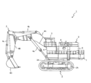
- the first embodiment of the work machine according to the present invention is configured by a large hydraulic excavator 1 used in an open pit operation or the like, for example, as shown in FIG.
- the hydraulic excavator 1 includes a traveling body 2 including a crawler traveling device 2A, a revolving body 3 provided on the upper side of the traveling body 2 via a revolving device 3A, and a front side of the revolving body 3.
- a front work machine 4 that is attached and pivots in the vertical direction to perform work such as excavation.
- the swivel body 3 is disposed at the front, and a driver's cab 5 on which an operator who operates the front work machine 4 is boarded, a driver's cab bed 6 disposed below the driver's cab 5 and supporting the driver's cab 5, and a rear part. And a counterweight 7 that maintains the balance of the vehicle body so that the vehicle body does not tilt, and is disposed between the cab bed 6 and the counterweight 7, and an engine 20 and hydraulic pumps 21 to 23 described later (see FIG. 2), and a controller 9 for controlling the entire operation of the vehicle body including the discharge flow rates of the hydraulic pumps 21 to 23 and the like.
- the front work machine 4 has a base end rotatably attached to the revolving body 3 and a boom 4A that rotates in the vertical direction with respect to the vehicle body, and a boom 4A that is rotatably attached to the tip of the boom 4A.
- the arm 4B that pivots in the vertical direction and the bucket 4C that is pivotally attached to the tip of the arm 4B and pivots in the vertical direction with respect to the vehicle body are included.
- the front work machine 4 connects the revolving unit 3 and the boom 4A, connects the boom cylinder 4a that rotates the boom 4A by expanding and contracting, the boom 4A and the arm 4B, and extends and contracts the arm 4B.
- the arm cylinder 4b that rotates the bucket 4C and the bucket cylinder 4c that connects the arm 4B and the bucket 4C and rotates the bucket 4C by expanding and contracting are included.
- boom cylinder 4a, arm cylinder 4b, and bucket cylinder 4c function as actuators to constitute hydraulic cylinders 11 (see FIG. 2) that are driven by pressure oil.
- the boom cylinder 4a, the arm cylinder 4b, and the bucket cylinder 4c will be collectively referred to as the hydraulic cylinder 11 unless particularly distinguished.
- the cab 5 is electrically connected to the controller 9 and includes an operation lever 5A (see FIG. 3) as an operation device for operating the hydraulic cylinder 11, and the hydraulic excavator 1 including the states of the hydraulic pumps 21-23.
- a notification device that notifies the operator of information regarding each device, for example, a monitor 5B that displays the information as video or characters is included.
- the operation direction and operation speed of the hydraulic cylinder 11 are set in advance according to the operation direction and operation amount of the operation lever 5A.
- the notification device may be configured by a sound output device such as a speaker that outputs information related to each device of the excavator 1 by sound, instead of the monitor 5B.
- the controller 9 is not illustrated, but includes a CPU (Central Processing Unit) that performs various calculations for controlling the entire operation of the vehicle body, and a ROM (Read Only Memory) that stores a program for executing calculations by the CPU. It is composed of hardware including a storage device such as an HDD (Hard Disk Drive) and a RAM (Random Access Memory) serving as a work area when the CPU executes a program.
- a CPU Central Processing Unit
- ROM Read Only Memory
- HDD Hard Disk Drive
- RAM Random Access Memory
- a program stored in a recording medium such as a ROM, an HDD, or an optical disk (not shown) is read into the RAM, and the program (software) and the hardware cooperate by operating under the control of the CPU.
- achieves the function of the controller 9 is comprised. The details of the functional configuration of the controller 9 that characterizes the first embodiment of the present invention will be described later.
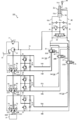
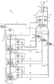
- FIG. 2 is a diagram showing a configuration of a hydraulic circuit 100 for driving the hydraulic cylinder 11 according to the first embodiment of the present invention.
- the hydraulic cylinder 11 is slidably accommodated in the cylinder tube 11A to which pressure oil is supplied, and the cylinder tube 11A, and the inside of the cylinder tube 11A is a head-side oil chamber (or bottom chamber).
- 11a and a rod-side oil chamber 11b, and a piston rod 11C that is partly housed in the rod-side oil chamber 11b of the cylinder tube 11A and that has a base end connected to the piston 11B.
- the hydraulic circuit 100 is provided inside the revolving structure 3 and drives the hydraulic cylinder 11 according to the operation of the operation lever 5A in the cab 5.
- this hydraulic circuit 100 includes an engine 20 as a prime mover, and a plurality of variable displacement hydraulic pumps that are driven by the engine 20 with an input shaft provided coaxially with an output shaft of the engine 20 (this embodiment).
- three hydraulic pumps) 21 to 23 are provided, and volume control for controlling the speed of the hydraulic cylinder 11 by adjusting the discharge flow rate of these hydraulic pumps 21 to 23 is performed.
- the hydraulic circuit 100 joins the hydraulic oil discharged from the hydraulic pumps 21 to 23 to act on the hydraulic cylinder 11, and connects the hydraulic cylinder 11 and the hydraulic pumps 21 to 23 in the junction circuit 24.
- Switching valves 25 to 27 for switching, a speed sensor 28 that is electrically connected to the controller 9 and detects the speed of the hydraulic cylinder 11, and hydraulic oil to be supplied to the hydraulic pumps 21 to 23 are stored.
- a hydraulic oil tank 29 is provided.
- a charge pump 31 is connected to the output shaft of the engine 20.
- the discharge side of the charge pump 31 is connected to the conduit 12, and the conduit 12 is connected to the hydraulic oil tank 29 via the relief valve 32.
- the relief valve 32 discharges the hydraulic oil in the pipe line 12 to the hydraulic oil tank 29 when the pressure in the pipe line 12 becomes equal to or higher than a preset pressure.
- the suction side of the charge pump 31 is connected to the hydraulic oil tank 29, and the charge pump 31 sucks the hydraulic oil in the hydraulic oil tank 29 and discharges it to the conduit 12.
- the engine 20 is provided with a rotation speed sensor 20A for detecting the rotation speed of the engine 20, that is, the rotation speeds of the hydraulic pumps 21 to 23.
- the rotation speed sensor 20A is electrically connected to the controller 9. It is connected.
- the hydraulic pump 21 has a pair of input / output ports 21A, 21B for sucking or discharging hydraulic oil, and a tilt for adjusting the amount of hydraulic oil sucked / discharged and the direction of suction / discharge of these input / output ports 21A, 21B.
- a bi-tilt swash plate mechanism including a rotary swash plate 21C is provided.
- the hydraulic pump 21 is provided with a regulator 21D that is a device that controls the volume of the hydraulic pump 21 by adjusting the tilt angle of the swash plate 21C.
- the regulator 21D is electrically connected to the controller 9, and controls the suction / discharge flow rate and the suction / discharge direction of each of the input / output ports 21A, 21B of the hydraulic pump 21 by an electrical control signal transmitted from the controller 9. .
- the pair of input / output ports 21A and 21B of the hydraulic pump 21 has a conduit 14A connected to the head side oil chamber 11a of the hydraulic cylinder 11 and a conduit 14B connected to the rod side oil chamber 11b of the hydraulic cylinder 11. , Are provided respectively.
- One end of this pipeline 14A is connected to one input / output port 21A of the hydraulic pump 21, and the other end of the pipeline 14A is connected to the pipeline 13A connected to the head side oil chamber 11a of the hydraulic cylinder 11 with a switching valve 25. Connected through.
- One end of the conduit 14B is connected to the other input / output port 21B of the hydraulic pump 21, and the other end of the conduit 14B is connected to the conduit 13B connected to the rod side oil chamber 11b of the hydraulic cylinder 11 with the switching valve 25. Connected through. Therefore, the hydraulic cylinder 11 and the hydraulic pump 21 are connected in a closed circuit shape via the pipelines 13A, 13B, 14A, 14B and the switching valve 25, and constitute a closed circuit 241 that directly drives the hydraulic cylinder 11 by the hydraulic pump 21. is doing.
- the closed circuit 241 connects the low-pressure side pipe line of the pipe lines 13A and 13B to the pipe line 12, and discharges the hydraulic oil in the low-pressure side pipe line to the pipe line 12, and the pipe Relief valves 41 and 42 for discharging hydraulic oil in the pipelines 13A and 13B to the pipeline 12 and pressures in the pipelines 13A and 13B when the pressure in the channels 13A and 13B becomes equal to or higher than a preset pressure.
- the make-up valve 43, 44 for supplying the hydraulic oil discharged from the charge pump 31 to the pipelines 13A, 13B when the pressure becomes less than a preset pressure.
- the closed circuit 241 includes relief valves 51 and 52 for discharging the hydraulic oil in the pipelines 14A and 14B to the pipeline 12 when the pressure in the pipelines 14A and 14B is equal to or higher than a preset pressure, Makeup valves 53 and 54 for supplying hydraulic oil discharged from the charge pump 31 to the pipelines 14A and 14B when the pressure in the pipelines 14A and 14B becomes less than a preset pressure; Pressures as pressure detectors that are attached to the input / output ports 21A and 21B of the hydraulic pump 21 in the pipelines 14A and 14B and detect the pressure in the pipelines 14A and 14B, that is, the suction and discharge pressures of the hydraulic pump 21, respectively. Sensors 55 and 56 are included. These pressure sensors 55 and 56 are electrically connected to the controller 9.
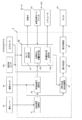
- the controller 9 includes a target speed calculation unit 91 that calculates a target speed for operating the hydraulic cylinder 11 based on the operation amount of the operation lever 5A, and the hydraulic cylinder detected by the speed sensor 28. 11 and a target speed calculated by the target speed calculator 91, a target drive pressure calculator 92 for calculating a target drive pressure for driving the hydraulic cylinder 11, and pressure sensors 55, 56, 65, 66. , 75 and 76, the hydraulic pumps 21 to 23 and the switching valves 25 to 27 according to the pressures of the input / output ports 21A to 23A and 21B to 23B and the target drive pressure calculated by the target drive pressure calculator 92. And a pump / switching valve control section 93 for controlling the operation of the above.
- the target speed calculation unit 91 the relationship between the operation amount of the operation lever 5A and the target speed of the hydraulic cylinder 11 is stored in advance.
- the target speed calculation unit 91 inputs an operation signal for the operation lever 5A and applies the operation amount of the operation lever 5A to the above relationship, thereby calculating the target speed of the hydraulic cylinder 11 based on the above relationship.
- the hydraulic cylinder 11 when the speed polarity of the hydraulic cylinder 11 is positive, the hydraulic cylinder 11 performs an expansion operation, and when the speed polarity of the hydraulic cylinder 11 is negative, the hydraulic cylinder 11 contracts. Shall be performed.
- the target drive pressure calculation unit 92 matches the speed of the hydraulic cylinder 11 with the target speed so as to eliminate the deviation between the speed of the hydraulic cylinder 11 detected by the speed sensor 28 and the target speed calculated by the target speed calculation unit 91. A target driving pressure required for the calculation is calculated.
- the target drive pressure calculation unit 92 outputs the calculated target drive pressure to the pump / switching valve control unit 93 as the sum of the target discharge pressures of the hydraulic pumps 21 to 23.
- the pump / switching valve control unit 93 selects a hydraulic pump for driving the hydraulic cylinder 11 among the hydraulic pumps 21 to 23, and the hydraulic pumps 21 to 23 according to the selection result of the pump selection unit 931.
- the target discharge flow rate calculation unit 932 that calculates the target discharge flow rate of the hydraulic pump 21 and the target discharge flow rate of the hydraulic pumps 21 to 23 calculated by the target discharge flow rate calculation unit 932, that is, And a volume command value calculation unit 933 for calculating a corresponding volume command value.
- the pump selection unit 931 transmits a control signal for keeping the switching position in the open position to the switching valve corresponding to the selected hydraulic pump among the switching valves 25 to 27, and transmits the control signal to the other switching valves. A control signal for keeping the switching position in the closed position is transmitted. Details of the selection process of the hydraulic pumps 21 to 23 by the pump selection unit 931 will be described later.
- the target discharge flow rate calculation unit 932 includes the pressure on the discharge side of the input / output port detected by the pressure sensor corresponding to the hydraulic pump selected by the pump selection unit 931, and the target drive pressure calculated by the target drive pressure calculation unit 92.
- the target discharge flow rate of the discharge pressure of the corresponding hydraulic pump is calculated so as to eliminate the deviation.
- the hydraulic pump 21 when the polarity of the target discharge flow rate of the hydraulic pump 21 is positive, the hydraulic pump 21 sucks hydraulic oil from the input / output port 21B and discharges it from the input / output port 21A.
- the hydraulic pump 21 draws hydraulic oil from the input / output port 21A and discharges it from the input / output port 21B.
- the target discharge flow rate calculation unit 932 obtains an amount to be allocated to each of the hydraulic pumps 21 to 23 out of the target discharge flow rate according to the selection result of the hydraulic pumps 21 to 23 by the pump selection unit 931.
- the volume command value calculation unit 933 is based on the selected target discharge flow rate of each of the hydraulic pumps 21 to 23 and the rotational speed of the engine 20 detected by the rotational speed sensor 20A, that is, the rotational speed of the hydraulic pumps 21 to 23.
- a volume command value for controlling the volume (push-off volume) of each of the hydraulic pumps 21 to 23 is calculated.
- the pump / switching valve control unit 93 transmits the control signal of the volume command value calculated by the volume command value calculation unit 933 to the regulators 21D to 23D of the corresponding hydraulic pumps 21 to 23, and the pump selection unit.
- the selection result of 931, the calculation result of the target discharge flow rate calculation unit 932, and the calculation result of the volume command value calculation unit 933 are transmitted to the volume transfer efficiency calculation unit 94 described later.
- the pump / switching valve control unit 93 functions as a target command value acquisition unit that acquires target command values of the discharge flow rates of the hydraulic pumps 21 to 23.
- the controller 9 also detects the speed of the hydraulic cylinder 11 detected by the speed sensor 28, the rotation speeds of the hydraulic pumps 21 to 23 detected by the rotation speed sensor 20A, the selection result of the pump selection unit 931, and the target discharge flow rate calculation unit 932.
- the volume transfer efficiency calculation for calculating the volume transfer efficiency ⁇ C indicating the transfer efficiency of the hydraulic oil between the hydraulic cylinder 11 and the hydraulic pumps 21 to 23 based on the calculation result of the above and the calculation result of the volume command value calculation unit 933 Part 94 is included.
- the controller 9 determines whether there is an abnormality such as wear or failure in any of the hydraulic pumps 21 to 23 based on the volume transfer efficiency ⁇ C calculated by the volume transfer efficiency calculation unit 94. 95 and a notification control unit 96 that performs control to display the determination result on the monitor 5B when the abnormality determination unit 95 determines that any of the hydraulic pumps 21 to 23 is abnormal.
- the switching valve 25 is switched to the open position 25A, and the switching valves 26 and 27 are switched to the closed position 25B.
- the case of driving will be described. Note that the same applies to the case where the hydraulic cylinders 11 are driven only by the other hydraulic pumps 22 and 23, respectively, and redundant description is omitted.
- the hydraulic circuit 100 is a system that performs volume control as described above, the flow rate of the hydraulic oil discharged from the hydraulic pump 21 is determined by the pressure in the hydraulic circuit 100 being the relief valve 41. , 42, 51, 52, the entire amount of hydraulic oil excluding minute leakage at each part of the closed circuit 241 flows into the hydraulic cylinder 11 unless the hydraulic oil flows out to the pipe line 12.
- the pressure in each of the pipelines 13A, 13B, 14A, 14B which is a path connecting the hydraulic cylinder 11 and the hydraulic pump 21, is less than the set pressure of the relief valves 41, 42, 51, 52, and makeup is performed.
- the pressure is higher than the pressure in the pipe 12 on the upstream side of the valves 43, 44, 53, 54, and hydraulic oil flows out and in between the pipes 13 A, 13 B, 14 A, 14 B and the pipe 12. It is assumed that there is no.
- the theoretical value Q OUT of the discharge flow rate when the volumetric efficiency of the hydraulic pump 21 is 100% is C, where the volume command value per rotation of the hydraulic pump 21 is C, and the rotation speed of the hydraulic pump 21 is R. It is represented by the following mathematical formula (1).
- the flow rate QIN of the hydraulic oil flowing into the hydraulic cylinder 11 is expressed by the following formula (2), where V is the speed of the hydraulic cylinder 11 and A is the pressure receiving area of the piston 11B of the hydraulic cylinder 11.
- this mathematical formula (3) becomes the following mathematical formula (4).
- the speed V of the hydraulic cylinder 11 is proportional to the volume command value C of the hydraulic pump 21 from this equation (4).
- volumetric efficiency mainly due to internal leakage of the hydraulic pump 21 itself and an influence of leakage of each part of the closed circuit 241, so that the inflow flow rate Q of hydraulic oil to the hydraulic cylinder 11 IN becomes smaller than the theoretical value Q OUT of the discharge flow rate of the hydraulic pump 21 and fluctuates.
- the volume transfer efficiency ⁇ C is defined as the ratio of the flow rate Q IN of the hydraulic oil flowing into the hydraulic cylinder 11 with respect to the discharge flow rate Q OUT of the hydraulic pump 21. That is, the volume transfer efficiency ⁇ C is expressed by the following formula (5) from the formulas (1) and (2).
- the volume transfer efficiency calculating unit 94 includes a pressure receiving area A of the piston 11B of the hydraulic cylinder 11 stored in advance in the controller 9, a speed V of the hydraulic cylinder 11 detected by the speed sensor 28, and a rotation.
- the theoretical value of the volume transfer efficiency ⁇ C calculated by the volume transfer efficiency calculating unit 94 is 1. As the volume transfer efficiency ⁇ C becomes smaller than this value, the speed of the hydraulic cylinder 11 according to the volume command value is obtained. This means that the performance of the hydraulic pump 21 is degraded. However, even if the hydraulic pumps 21 to 23 are in a normal state, the volume transfer efficiency ⁇ C becomes smaller than the theoretical value due to the above-described problems such as internal leakage.
- the volume transfer efficiency ⁇ C calculated by the above is within a preset normal value range, it is determined that there is no abnormality in the hydraulic pump 21, and the volume transfer efficiency ⁇ C calculated by the volume transfer efficiency calculation unit 94 is determined. Is outside the range of the normal value set in advance, it is determined that there is an abnormality in the hydraulic pump 21.
- the discharge flow rate of the hydraulic pump 21 may be greater than or equal to the discharge flow rate corresponding to the volume command value due to the abnormality of the regulator 21D that controls the volume of the hydraulic pump 21 or the system that transmits the control signal of the volume command value. possible.
- the volume transfer efficiency ⁇ C calculated by the volume transfer efficiency calculating unit 94 is increased from the normal value.
- the accuracy necessary and sufficient to satisfy the accuracy required for the determination result of the abnormality of the hydraulic pump 21 is the same as when the volume transmission efficiency ⁇ C of the hydraulic pump 21 is lowered. I just need it.
- the volume transfer efficiency ⁇ C calculated by the volume transfer efficiency calculation unit 94 exceeds 1, which is the theoretical value, it is certain that an abnormality has occurred in the hydraulic pump 21, so the range of normal values is not necessarily limited. Even if it is not accurately grasped, it is possible to determine an obvious abnormality of the hydraulic pump 21.
- the pump selection unit 931 switches the switching valves 25 to 27 to the open positions 25A to 27A or the closed positions 25B to 27B, so that the plurality of hydraulic pumps 21 to 23 are controlled. It is possible to select how many of the hydraulic cylinders 11 are driven and which hydraulic pump is used. For example, if the pump selection unit 931 selects three hydraulic pumps 21 to 23, the volume transfer efficiency ⁇ C at this time is obtained by changing the volume command value of each hydraulic pump 21 to 23 to C 1 , C 2 , C If it is 3 , it is represented by the following mathematical formula (6). Of the volume command values C 1 , C 2 , and C 3 of the hydraulic pumps 21 to 23, the volume command value that is not connected to the hydraulic cylinder 11 is zero.
- the volume transfer efficiency ⁇ C obtained by the equation (6) is the sum of the volume command values C 1 , C 2 and C 3 of the hydraulic pumps 21 to 23, and is relative to the total value of the discharge flow rates of the hydraulic pumps 21 to 23. since is defined as the ratio of the inlet flow of the hydraulic fluid to the hydraulic cylinder 11, in this volume only transmission efficiency eta C can not be determined for the presence or absence of abnormality of each hydraulic pump 21-23.
- identifies the hydraulic pump is a cause of lowering these volumetric transmission efficiency eta C, and so as to determine the presence or absence of abnormality of the hydraulic pump.
- an abnormality diagnosis mode setting unit for setting an abnormality diagnosis mode for diagnosing an abnormality of each of the hydraulic pumps 21 to 23 is provided.
- This abnormality diagnosis mode setting unit is installed, for example, in the cab 5 and is configured from an abnormality diagnosis mode switch 5C that is pressed by the operator.
- the controller 9 connects the hydraulic cylinder 11 of one system and only one hydraulic pump among the hydraulic pumps 21 to 23 by the switching valves 25 to 27. In this state, the abnormality determination unit 95 determines the abnormality of the hydraulic pump.
- the hydraulic circuit 100 As in the hydraulic circuit 100 according to the first embodiment of the present invention, even in a system that drives a single hydraulic cylinder 11 by joining hydraulic oil discharged from a plurality of hydraulic pumps 21 to 23, the hydraulic cylinder If only one hydraulic pump is connected to 11 at the same time, the volume transfer efficiency ⁇ C between the hydraulic cylinder 11 and the hydraulic pump can be obtained.
- the controller 9 causes the pump selection unit 931 to select one of the hydraulic pumps 21 to 23 and change the hydraulic pumps connected to the hydraulic cylinder 11 in order, so that there is an abnormality in all the hydraulic pumps 21 to 23. Can be determined individually.
- the abnormality diagnosis mode is not set by the abnormality diagnosis mode switch 5C, the abnormality of the hydraulic pumps 21 to 23 can be detected without hindering the normal operation of the excavator 1.
- the hydraulic cylinder 11 is in operation during the operation of the hydraulic excavator 1. Since a scene of low speed operation appears at the discharge flow rate of one of the hydraulic pumps 21 to 23, the abnormality determination unit 95 uses the volume transmission efficiency ⁇ C obtained at that timing to detect the abnormality of the hydraulic pumps 21 to 23. Determine presence or absence.
- the abnormality determination unit 95 cannot determine whether there is an abnormality in the other hydraulic pumps. It is necessary to change the connection method with the hydraulic cylinder 11. Therefore, the pump selection unit 931 changes the hydraulic pump used at the time of the low speed operation of the hydraulic cylinder 11 each time, so that the abnormality determination unit 95 can detect the abnormality of all the hydraulic pumps 21 to 23 while the hydraulic excavator 1 is operating. The presence or absence of can be determined.
- the volume transfer efficiency ⁇ C is calculated as the time during which the hydraulic cylinder 11 is driven by only one hydraulic pump among the hydraulic pumps 21 to 23 becomes shorter. The accuracy of the result is reduced.
- it is determined whether there is an abnormality for each of the hydraulic pumps 21 to 23. It is desirable to do it.
- the hydraulic circuit 100 is a system that drives one hydraulic cylinder 11 by combining hydraulic oil discharged from a plurality of hydraulic pumps 21 to 23.
- the number of connected hydraulic pumps 21 to 23 is less than the maximum number connectable by the switching valves 25 to 27 (hereinafter referred to as the maximum number of connected units for convenience), that is, two or less, the hydraulic pressure connected to the hydraulic cylinder 11
- the maximum number of connected units for convenience
- the volume transfer efficiencies ⁇ C12 , ⁇ C23 , ⁇ C13 , and ⁇ C123 obtained by these formulas (7) to (10) satisfy the relationship of the following formula (11)
- the volume transfer efficiencies ⁇ C12 in each combination , ⁇ C23 , ⁇ C13 , and ⁇ C123 are caused by the hydraulic pump 21.
- the abnormality determination unit 95 estimates the decrease in the volume transfer efficiency ⁇ C12 , ⁇ C23 , ⁇ C13 , and ⁇ C123 .
- the controller 9 connects the hydraulic cylinder 11 and the hydraulic pumps 21 to 23 when the number of hydraulic cylinders 11 and the hydraulic pumps 21 to 23 is less than the maximum number of units connected. Every time the number is changed, the switching operation of the switching valves 25 to 27 is controlled so that the combination of the hydraulic pumps 21 to 23 connected to the hydraulic cylinder 11 is different.
- the pump selection unit 931 is connected to the hydraulic cylinder 11 every time the hydraulic excavator 1 is in operation and the required speed of the hydraulic cylinder 11 becomes a speed that can be covered by the discharge flow rate of the hydraulic pump that is less than the maximum number of connections.
- the hydraulic pump that drives the hydraulic cylinder 11 is selected from the hydraulic pumps 21 to 23 so that all kinds of combinations of the hydraulic pumps 21 to 23 to be changed are sequentially changed.
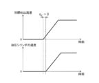
- FIG. 4 is a diagram showing an example of the transition of the relationship between the speed of the hydraulic cylinder 11 and the connection state between the hydraulic cylinder 11 and the hydraulic pumps 21 to 23 according to the first embodiment of the present invention.
- the number of connections N between the hydraulic cylinder 11 and each of the hydraulic pumps 21 to 23 is 1, 2, 3, 2, 3, 2 and 1 in order.
- the state where the number of connected units N is 1 appears twice
- the state where the number of connected units N is 2 appears three times
- the state where the number of connected units N is 3 appears twice.
- the combination of the hydraulic pumps connected to the hydraulic cylinder 11 is changed between the first time and the second time when the number N of connected units is one, and the first time is the hydraulic pump 21 and the second time is the hydraulic pump 22. .
- the combination of the hydraulic pumps connected to the hydraulic cylinder 11 is changed in the first, second, and third times when the number N of connected units is two, and the first time is the hydraulic pump 21 and the hydraulic pump 22.
- the third time is the hydraulic pump 22 and the hydraulic pump 23, and the third time is the hydraulic pump 21 and the hydraulic pump 23. Since the maximum number of hydraulic pumps 21 to 23 is connected to the hydraulic cylinder 11 in the first and second times when the number N of connected units is 3, the combination of the hydraulic pumps connected to the hydraulic cylinder 11 Is not changed, and the hydraulic pump 21, the hydraulic pump 22, and the hydraulic pump 23 are used for the first time and the second time.
- the hydraulic pump connected to the hydraulic cylinder 11 for the third time in a state where the number of connected N is one becomes the hydraulic pump 23 different from the first time and the second time. Further, in the state where the number of connected units N is two, there are three combinations of hydraulic pumps connected to the hydraulic cylinders 11, and therefore the hydraulic pump connected to the hydraulic cylinders 11 for the fourth time has the same hydraulic pressure as the first time.
- a pump 21 and a hydraulic pump 22 are provided.
- the volume transfer efficiency calculating unit 94 causes the volume transfer efficiency ⁇ C12 , ⁇ C23 , ⁇ C13 , ⁇ in all types of combinations.
- C123 can be obtained in the shortest time.
- the frequency of the combinations of the hydraulic pumps 21 to 23 connected to the hydraulic cylinder 11 does not greatly deviate , it takes a long time to obtain the volume transfer efficiency ⁇ C12 , ⁇ C23 , ⁇ C13 , and ⁇ C123 in all types of combinations. Therefore, it is not always necessary to change the combination of the hydraulic pumps 21 to 23 connected to the hydraulic cylinder 11 according to the above-mentioned rules strictly.
- the combination of the hydraulic pumps 21 to 23 connected to the hydraulic cylinders 11 is randomly changed or the number N of connected pumps increases.
- the switching valve corresponding to the connected hydraulic pump is kept in the open position before the number N of connected valves increases, and other hydraulic pumps A rule may be set in the controller 9 for switching the switching valve corresponding to 1 from the closed position to the open position.
- the hydraulic cylinder 11 and the other hydraulic pump 22 or the hydraulic pump 23 are additionally connected while maintaining the state in which only the hydraulic pump 21 is connected to the hydraulic cylinder 11.
- the energy saving of the excavator 1 can be achieved, and the operability of the hydraulic cylinder 11 can be improved.
- the notification control unit 96 causes the abnormality determination unit 95 to reduce any of the volume transmission efficiencies ⁇ C12 , ⁇ C23 , ⁇ C13 , and ⁇ C123. If it is estimated that the operator is in the operator's cab 5, the monitor 5B is controlled to display a message or the like that prompts the operator in the cab 5 to set the abnormality diagnosis mode. Therefore, the controller 9 according to the first embodiment of the present invention specifies the hydraulic pump that is suspected of being abnormal among the hydraulic pumps 21 to 23, and more accurately determines the abnormality of the hydraulic pump to be diagnosed by the abnormality diagnosis mode. Can be detected.
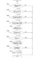
- the controller 9 determines whether or not the absolute value of the target discharge flow rate calculated by the target discharge flow rate calculation unit 932 of the pump / switching valve control unit 93 is greater than or equal to a preset threshold value Qa. Judgment ((Step (hereinafter referred to as S) 501)). At this time, when the controller 9 determines that the absolute value of the target discharge flow rate calculated by the target discharge flow rate calculation unit 932 is less than the threshold value Qa (S501 / No), the process of S501 is repeated.
- the controller 9 sets threshold values Qa and Va to be compared with the calculation result of the target discharge flow rate calculation unit 932 and the detection result of the speed sensor 28, and sets the target discharge flow rate of each of the hydraulic pumps 21 to 23. Only when both the absolute value and the absolute value of the speed of the hydraulic cylinder 11 are equal to or higher than the threshold values Qa and Va, the abnormality detection processing of the hydraulic pumps 21 to 23 is advanced. As a result, the obtained volume transmission efficiency ⁇ C can appropriately reflect the state of the hydraulic pumps 21 to 23, so that a highly accurate detection result can be obtained.
- the threshold values Qa and Va are set according to the accuracy required for the abnormality detection results of the hydraulic pumps 21 to 23 and the speed of the detection process. For example, if the threshold values Qa and Va are set with reference to the vicinity of the maximum speed of the hydraulic cylinder 11 reached only at an extremely light load, the width of the volume transfer efficiency ⁇ C regarded as a normal value range can be set small. Although the accuracy of the abnormality detection results 21 to 23 can be increased, the frequency with which the hydraulic cylinder 11 satisfies the reference speed during operation of the hydraulic excavator 1 decreases. Therefore, there is a high possibility that it will take time until the decrease in the volume transfer efficiency ⁇ C is estimated. Therefore, when importance is attached to the speed of the abnormality detection processing of the hydraulic pumps 21 to 23, the threshold values Qa and Va are set. It is preferable to relax the standard of the hydraulic cylinder 11 for setting.
- volume transfer efficiency ⁇ C may vary greatly due to the dynamic characteristics of the hydraulic system and the control system in the hydraulic circuit 100.
- specific examples of fluctuations in the volume transfer efficiency ⁇ C due to the dynamic characteristics of these hydraulic systems and control systems will be described in detail with reference to FIGS. 6 and 7.
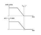
- the operator operates the operation lever 5A from the state in which the hydraulic cylinder 11 is operating at a speed corresponding to the target discharge flow rate of the hydraulic pumps 21 to 23, so that the target of the hydraulic pumps 21 to 23 is reached.
- the discharge flow rate is set to 0
- the response of the speed of the hydraulic cylinder 11 is delayed, and the hydraulic cylinder 11 is still operating.
- the volume transfer efficiency ⁇ C calculated by the volume transfer efficiency calculating unit 94 is infinite from Equation (6).
- the volume transfer efficiency ⁇ C does not serve as an index for determining abnormality of the hydraulic pumps 21 to 23. Therefore, the target discharge flow rate of the hydraulic pumps 21 to 23 and the speed of the hydraulic cylinder 11 can be regarded as steady. In the state, it is necessary to calculate the volume transfer efficiency ⁇ C by the volume transfer efficiency calculation unit 94.
- the absolute value of the time change rate of the target discharge flow rate calculated by the target discharge flow rate calculation unit 932 is less than a preset threshold value ⁇ Qa (S503 / Yes), and the hydraulic cylinder 11 detected by the speed sensor 28 is detected. Only when the absolute value of the rate of time change in speed is less than a preset threshold value ⁇ Va (S504 / Yes), the volume transfer efficiency calculating unit 94 of the controller 9 is connected to the hydraulic cylinder 11 in accordance with a preset rule.
- the volume transfer efficiency ⁇ C is calculated for each combination of the hydraulic pumps 21 to 23 (S505).
- the abnormality determination unit 95 of the controller 9 inputs the calculation result of the volume transfer efficiency calculation unit 94, and any of the volume transfer efficiency ⁇ C in each combination calculated by the volume transfer efficiency calculation unit 94 decreases. It is estimated whether it exists (S506). At this time, if the abnormality determining unit 95 determines that none of the volume transfer efficiency ⁇ C in each combination has decreased (S506 / No), the processing from S501 is repeated.
- the pump / switching valve control unit 93 determines the hydraulic pump identified by the hydraulic cylinder 11 and the abnormality determination unit 95, that is, abnormality diagnosis. After switching the switching valves 25 to 27 so that only the hydraulic pump to be diagnosed in the mode is connected, the volume transmission efficiency calculating unit 94 performs the volume transmission efficiency between the hydraulic cylinder 11 and the hydraulic pump to be diagnosed. ⁇ C is calculated (S508).
- the abnormality determination unit 95 inputs the calculation result of the volume transfer efficiency calculation unit 94, and whether the volume transfer efficiency ⁇ C calculated by the volume transfer efficiency calculation unit 94 is outside the preset normal value range. It is confirmed whether or not (S509). At this time, when the abnormality determining unit 95 confirms that the volume transfer efficiency ⁇ C is within the normal value range (S509 / No), the abnormality determining unit 95 determines that there is no abnormality in the diagnosis target hydraulic pump, and the processing from S501 is performed. Repeated.
- the abnormality determination unit 95 is detected by the target discharge flow rate calculated by the target discharge flow rate calculation unit 932 and the speed sensor 28. By confirming whether or not the volume transfer efficiency ⁇ C obtained from the speed of the hydraulic cylinder 11 deviated from the preset normal value range, a new flow sensor is not provided in the hydraulic circuit 100. In addition, it is possible to easily determine whether the hydraulic pumps 21 to 23 are abnormal.
- the volume transfer efficiency ⁇ C calculated by the volume transfer efficiency calculation unit 94 exceeds the upper limit of the normal value. It is displayed on the monitor 5B that an abnormality has occurred in .about.23. As a result, the operator in the cab 5 can grasp the abnormality of the hydraulic pumps 21 to 23 at an early stage, and can promptly respond to the abnormality of the hydraulic pumps 21 to 23.
- control device for the hydraulic excavator 1 can accurately detect abnormality of the hydraulic pumps 21 to 23 including the control devices such as the regulators 21D to 23D while suppressing the equipment cost. Therefore, it is possible to realize excellent economic efficiency and to improve the reliability of the abnormality detection processing of the hydraulic pumps 21 to 23.
- the second embodiment of the present invention differs from the first embodiment described above in that the volume transfer efficiency calculation unit 94 according to the first embodiment transfers the volume transfer efficiency ⁇ C to the hydraulic cylinder 11 with respect to the discharge flow rate of the hydraulic pump 21.
- the volume transfer efficiency calculation ⁇ C on the discharge side of the hydraulic pumps 21 to 23 in the closed circuits 241 to 243 is calculated, whereas the volume transfer efficiency calculation according to the second embodiment is calculated.
- the section 94 is configured to calculate the volume transfer efficiency ⁇ C on the suction side of the hydraulic pumps 21 to 23 in the closed circuits 241 to 243.
- the volume transfer efficiency calculating unit 94 includes both input / output ports of the hydraulic pumps 21 to 23 detected by the pressure sensors 55, 56, 65, 66, 75, and 76.
- the hydraulic pumps 21 to 23A, 21A to 23A, 21B to 23B correspond to the combinations of the pressure magnitudes and the discharge directions of the hydraulic pumps 21 to 23 represented by the target command values acquired by the pump / switching valve controller 93.
- the ratio of the flow rate of hydraulic oil flowing into the hydraulic cylinder 11 with respect to the discharge flow rate of 23 and the ratio of the suction flow rates of the hydraulic pumps 21 to 23 with respect to the flow rate of hydraulic oil from the hydraulic cylinder 11 are defined as the volume transfer efficiency ⁇ C. I try to calculate.
- Other configurations of the second embodiment are the same as the configurations of the first embodiment, and the same or corresponding parts are denoted by the same reference numerals, and redundant description is omitted.
- the switching valve 25 is switched to the open position 25A, and the switching valves 26 and 27 are switched to the closed positions 26B and 27B, respectively, so that only one hydraulic pump 21 is used.
- the case where 11 is driven will be described. Note that the same applies to the case where the hydraulic cylinders 11 are driven only by the other hydraulic pumps 22 and 23, respectively, and redundant description is omitted.
- the flow rate of the hydraulic oil discharged from the charge pump 31 is the makeup valves 43, 44, 53. , 54 does not flow into the suction side of the hydraulic pump 21, and the flow rate of hydraulic oil flowing out from the hydraulic cylinder 11 corresponds to the suction flow rate of the hydraulic pump 21.
- the speed of the hydraulic cylinder 11 is controlled by the suction flow rate of the hydraulic pump 21.
- the volume transfer efficiency ⁇ C is defined as the ratio of the suction flow rate Q IN of the hydraulic pump 21 to the outflow flow rate Q OUT of the hydraulic oil from the hydraulic cylinder 11. That is, the volume transfer efficiency ⁇ C is expressed by the following mathematical formula (12).
- the range of the normal value of the volume transfer efficiency ⁇ C on the suction side of the hydraulic pump 21 may be set similarly to the range of the normal value of the volume transfer efficiency ⁇ C on the discharge side of the hydraulic pump 21.
- the range of volumetric transmission efficiency eta C of the previously measured to the normal value of volumetric transmission efficiency eta C of the suction side of the hydraulic pump 21 Therefore, the abnormality determination unit 95 can determine the presence or absence of abnormality of the hydraulic pump 21 with higher accuracy.
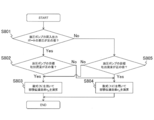
- volume transfer efficiency ⁇ C calculation processing by the volume transfer efficiency calculation unit 94 will be described in detail with reference to the flowchart of FIG.
- the pressure of the input / output port 21A of the hydraulic pump 21 is higher than the pressure of the input / output port 21B
- the polarity of the differential pressure of both the input / output ports 21A and 21B is assumed to be positive.
- the pressure of the output port 21B is higher than the pressure of the input / output port 21A, the polarity of the differential pressure between the input / output ports 21A and 21B is negative.
- the volume transmission efficiency calculating unit 94 inputs the detection values of the pressure sensors 55 and 56, and the input / output ports 21 ⁇ / b> A and 21 ⁇ / b> B of the hydraulic pump 21 detected by the pressure sensors 55 and 56 are input. It is determined whether or not the differential pressure is a positive value (S801). At this time, when the volume transfer efficiency calculating unit 94 determines that the differential pressure between the input / output ports 21A and 21B of the hydraulic pump 21 is a positive value (S801 / Yes), the target discharge from the pump / switching valve control unit 93 is determined.
- the calculation result of the flow rate calculation unit 932 is input, and it is determined whether or not the target discharge flow rate calculated by the target discharge flow rate calculation unit 932 is a positive value (S802).
- the hydraulic pump 21 sucks the hydraulic oil from the input / output port 21B and discharges it from the input / output port 21A, and the polarity of the target discharge flow rate of the hydraulic pump 21 is negative.
- the hydraulic pump 21 sucks hydraulic oil from the input / output port 21A and discharges it from the input / output port 21B.
- the volume transfer efficiency calculating unit 94 determines that the differential pressure between the input / output ports 21A and 21B of the hydraulic pump 21 is a negative value (S801 / No)
- the target discharge from the pump / switching valve control unit 93 is performed.
- the calculation result of the flow rate calculation unit 932 is input, and it is determined whether or not the target discharge flow rate calculated by the target discharge flow rate calculation unit 932 is a positive value (S805).
- the volume transfer efficiency ⁇ C when the hydraulic cylinder 11 is driven by the plurality of hydraulic pumps 21 to 23 is expressed by the following formula (13). Also in this case, the volume transfer efficiency ⁇ C is calculated by the volume transfer efficiency calculator 94 in the same manner as when the hydraulic cylinder 11 is driven by the single hydraulic pump 21 described above using the following formula (13). Done.
- the volume transfer efficiency calculation unit 94 can be a hydraulic pump. 21 to 23 discharge hydraulic fluid to the high-pressure side of the pipelines 14A to 16A and 14B to 16B, or the hydraulic pumps 21 to 23 are the high-pressure side of the pipelines 14A to 16A and 14B to 16B
- the volume transfer efficiency ⁇ C depending on whether the hydraulic oil is sucked from the hydraulic oil
- not only the volume transfer efficiency ⁇ C on the discharge side of the hydraulic pumps 21 to 23 but also the volume transfer efficiency on the suction side of the hydraulic pumps 21 to 23 ⁇ C can also be calculated.
- even when the operation in one direction of each of the hydraulic pumps 21 to 23 is normal and only the operation in the other direction is abnormal such a state can be accurately detected as an abnormality in the hydraulic pumps 21 to 23. it can.
- the configuration of the third embodiment of the present invention is based on the configuration of the second embodiment described above, and differs from the configuration of the second embodiment in the following points. That is, the volume transfer efficiency calculating unit 94 according to the third embodiment of the present invention includes both input / output ports 21A-23A of the hydraulic pumps 21-23 detected by the pressure sensors 55, 56, 65, 66, 75, 76. , 21B to 23B, and the hydraulic cylinders corresponding to the discharge flow rates of the hydraulic pumps 21 to 23 in accordance with the combination of the magnitude relationship between the pressures of the hydraulic cylinders 11 and the operation direction of the hydraulic cylinder 11 represented by the speed of the hydraulic cylinder 11 detected by the speed sensor 28.
- the volume transfer efficiency calculating unit 94 determines in S801 that the differential pressure between both the input / output ports 21A and 21B of the hydraulic pump 21 is a positive value (S801 / Yes), the speed sensor 28. Is detected, and it is determined whether or not the speed of the hydraulic cylinder 11 detected by the speed sensor 28 is a positive value (S901). At this time, if the volume transfer efficiency calculating unit 94 determines that the speed of the hydraulic cylinder 11 is a positive value (S901 / Yes), the process of S803 is performed. In S901, when the volume transfer efficiency calculating unit 94 determines that the speed of the hydraulic cylinder 11 is a negative value (S901 / No), the process of S804 is performed. In addition, when the polarity of the speed of the hydraulic cylinder 11 is positive, the hydraulic cylinder 11 performs an extension operation, and when the polarity of the speed of the hydraulic cylinder 11 is negative, the hydraulic cylinder 11 performs a contraction operation.
- the volume transfer efficiency calculating unit 94 determines in S801 that the differential pressure between the input / output ports 21A and 21B of the hydraulic pump 21 is a negative value (S801 / No), the detection value of the speed sensor 28 is input. Then, it is determined whether or not the speed of the hydraulic cylinder 11 detected by the speed sensor 28 is a positive value (S902). At this time, if the volume transfer efficiency calculating unit 94 determines that the speed of the hydraulic cylinder 11 is a positive value (S902 / Yes), the process of S804 is performed. In S902, when the volume transfer efficiency calculating unit 94 determines that the speed of the hydraulic cylinder 11 is a negative value (S902 / No), the process of S803 is performed.
- the volume transfer efficiency calculating unit 94 is the same as that of the second embodiment even in the same situation.
- the mathematical expression handled in the calculation process of the volume transfer efficiency ⁇ C differs.
- the volume transfer efficiency ⁇ C calculated by the volume transfer efficiency calculation unit 94 is a negative value regardless of which of the formula (5) and the formula (12) is used, and thus the volume transfer efficiency ⁇ C is clearly shown. Since it deviates from the range of the normal value, it is possible to accurately detect the abnormality of the hydraulic pumps 21 to 23.
- the volume transfer efficiency calculating unit 94 operates from the high-pressure side pipe line to the hydraulic cylinder 11 among the pipe lines 13A and 13B.
- the definition of the volume transfer efficiency ⁇ C is selectively used depending on whether the oil flows in or the hydraulic oil flows out from the hydraulic cylinder 11 to the high-pressure side of the pipes 13A and 13B. The same effect as the embodiment can be obtained.
- the hydraulic circuit 100 has been described with respect to the case where volume control is performed to adjust the discharge flow rate of the hydraulic pumps 21 to 23 to control the speed of the hydraulic cylinder 11, but the present invention is not limited to this case. It is not limited to.
- the flow rate of the hydraulic oil flowing into the hydraulic cylinder 11 is controlled only by the discharge flow rates of the hydraulic pumps 21 to 23, whereas the hydraulic oil from the hydraulic cylinder 11 is controlled.
- the outflow flow rate can be controlled by using not only the suction flow rates of the hydraulic pumps 21 to 23 but also a proportional valve 81 whose opening area is adjusted in accordance with a control signal from the controller 9 as shown in FIG.
- each embodiment of the present invention can also be applied to the hydraulic circuit 101 in which the proportional valve 81 is provided in the pipeline 17 branched from the pipeline 13A.
- a command value to the proportional valve 81 is also taken into consideration, and the outflow flow rate of the hydraulic oil from the proportional valve 81 to the hydraulic oil tank 29 is included.
- the volume transfer efficiency ⁇ C is preferably defined.
- each embodiment of this invention demonstrated the case where the number of hydraulic pumps was three, this invention is not limited to this case,
- the number of hydraulic pumps is two or four or more. There may be.
- the abnormality determination unit 95 determines whether there is an abnormality in each hydraulic pump from the volume transfer efficiency ⁇ C obtained while the hydraulic cylinder 11 is driven by only one hydraulic pump.
- the hydraulic shovel 1 which concerns on each embodiment of this invention demonstrated the case where the speed sensor 28 which can detect the speed of the hydraulic cylinder 11 directly was provided, this invention is limited to this case is not.
- the speed of the hydraulic cylinder 11 may be detected by obtaining a time derivative of the displacement of the hydraulic cylinder 11 obtained by converting the angle of the joint of the work machine 4.
- the hydraulic excavator 1 has been described with respect to the case where the hydraulic cylinder 11 as an actuator and a plurality of variable displacement hydraulic pumps 21 to 23 that drive the hydraulic cylinder 11 are described.
- the present invention is not limited to this case, and the types of the actuator and the hydraulic pump may be changed as appropriate.
- the actuator may be not only a single rod cylinder but also a double rod cylinder, or various hydraulic motors such as a traveling motor and a turning motor.
- the hydraulic pump may be a vane pump or the like as long as it is a variable displacement type.
- SYMBOLS 1 Hydraulic excavator (work machine), 4a ... Boom cylinder (actuator), 4b ... Arm cylinder (actuator), 4c ... Bucket cylinder (actuator), 5A ... Operation lever, 5B ... Monitor (notification device), 5C ... Abnormal diagnosis Mode switch (abnormality diagnosis mode setting unit), 9 ... controller, 11 ... hydraulic cylinder (actuator), 12, 13A to 16A, 13B to 16B, 17 ... pipe 20 ... engine, 20A ... rotational speed sensor, 21-23 ... Hydraulic pumps, 21A to 23A, 21B to 23B ... input / output ports, 21C to 23C ... swash plates, 21D to 23D ...
- regulators 24 ... merging circuits, 25 to 27 ... switching valves, 28 ... speed sensors (speed detectors), 55, 56, 65, 66, 75, 76 ... pressure sensor (pressure detector) DESCRIPTION OF SYMBOLS 91 ... Target speed calculating part, 92 ... Target drive pressure calculating part, 93 ... Pump / switching valve control part (target command value acquisition part), 94 ... Volume transfer efficiency calculating part, 95 ... Abnormality determination part, 96 ... Notification control part , 100, 101 ... Hydraulic circuit, 241 to 243 ... Closed circuit, 931 ... Pump selection unit, 932 ... Target discharge flow rate calculation unit, 933 ... Volume command value calculation unit
Landscapes
- Engineering & Computer Science (AREA)
- General Engineering & Computer Science (AREA)
- Mining & Mineral Resources (AREA)
- Civil Engineering (AREA)
- Structural Engineering (AREA)
- Mechanical Engineering (AREA)
- Physics & Mathematics (AREA)
- General Physics & Mathematics (AREA)
- Fluid Mechanics (AREA)
- Fluid-Pressure Circuits (AREA)
- Operation Control Of Excavators (AREA)
- Control Of Positive-Displacement Pumps (AREA)
Abstract
設備コストを抑制しつつ、制御機器を含む油圧ポンプの故障及び消耗等の異常を精度良く検知することができる作業機械の提供。 本発明に係るコントローラ9は、目標吐出流量演算部932によって演算された目標吐出流量、及び速度センサ28によって検出された油圧シリンダ11の速度に基づいて、油圧シリンダ11と油圧ポンプ21~23との間の作動油の伝達効率を示す容積伝達効率ηCを演算する容積伝達効率演算部94と、容積伝達効率演算部94によって演算された容積伝達効率ηCに基づいて、油圧ポンプ21~23のいずれかに異常があるかどうかを判定する異常判定部95とを有する。
Description
本発明は、油圧ポンプの故障及び消耗等の異常を検知する作業機械に関する。
油圧ショベル等の作業機械に搭載される油圧システムを長期間に渡って稼働させる場合、この油圧システムの主要な構成要素のうち、特に油圧ポンプは消耗による性能低下が避けられない。そのため、油圧ポンプを定期的に交換することにより、油圧システムとしての性能を維持するとともに、油圧ポンプの故障及び消耗等が生じるリスクを極力回避する事が一般的である。
しかし、このような予防的な措置は、油圧ポンプの消耗度合を過剰に見積もって交換サイクルの間隔を短くし過ぎるとコストアップとなり、あるいは逆に交換サイクルの間隔を空け過ぎたりして、作業に支障をきたす油圧ポンプの性能低下や故障の頻度を十分に抑制できないことがある。このため、作業機械の通常稼働中に精度良く油圧ポンプの状態を知る必要がある。この課題に対し、油圧ポンプの構成部品の摩耗によってその部品間の間隙が大きくなると、ドレン流量が増加する特性を利用し、油圧ポンプのドレン量を計測することで油圧ポンプの消耗度合を推定する従来技術がある。
更に他の従来技術として、複数の可変容量型油圧ポンプから吐出されてチェック弁を介して合流する圧油を所定のアクチュエータに供給して作業部材を駆動する油圧作業機に備えられ、複数の可変容量型油圧ポンプから吐出される総流量に基づいて、複数の可変容量型油圧ポンプのいずれかに機能低下が生じていないかどうかを監視する油圧作業機のポンプ監視装置が知られている(例えば、特許文献1参照)。
上述した前者のドレン流量が増加する特性を利用する従来技術は、油圧ポンプの性能低下とドレン流量の増加との関係の経験則に基づくので、油圧ポンプの消耗度合の推定精度を高めるためには、継続して取得したドレン流量の計測値を統計的に処理する必要がある。また、可変容量型油圧ポンプの容積を制御する機器、例えば、レギュレータの故障等の異常についてはドレン流量の計測値から推定することができないので、レギュレータの異常を検知する別の異常検知装置と併用しなければならない。
また、上述した後者の特許文献1の従来技術は、作業機械に搭載可能な寸法、重量、及び圧力損失等の諸条件を満たし、さらに可変容量型油圧ポンプからの圧油の吐出流量の検出精度も確保できる実流量検出手段としての流量センサの存在を前提としている。しかしながら、そのような流量センサは知られているものの、流量センサ自体が非常に高価であることから作業機械への搭載は現実的ではなく、実流量検出手段に適した流量センサを新たに開発する必要がある。そのため、特許文献1の従来技術は、設備コストの増大を招くことになり、経済的な面で実施が困難であることが懸念されている。
本発明は、このような従来技術の実情からなされたもので、その目的は、設備コストを抑制しつつ、制御機器を含む油圧ポンプの故障及び消耗等の異常を精度良く検知することができる作業機械を提供することにある。
上記の目的を達成するために、本発明の作業機械は、アクチュエータ、前記アクチュエータを駆動する複数の油圧ポンプ、前記複数の油圧ポンプから吐出した作動油を合流して前記アクチュエータに作用させる合流回路、及び前記複数の油圧ポンプの吐出流量を制御するコントローラを備えた作業機械において、前記アクチュエータの速度を検出する速度検出器を備え、前記コントローラは、前記複数の油圧ポンプの吐出流量の目標指令値を取得する目標指令値取得部と、前記目標指令値取得部によって取得された前記目標指令値、及び前記速度検出器によって検出された前記アクチュエータの速度に基づいて、前記アクチュエータと前記複数の油圧ポンプとの間の作動油の伝達効率を示す容積伝達効率を演算する容積伝達効率演算部と、前記容積伝達効率演算部によって演算された前記容積伝達効率に基づいて、前記複数の油圧ポンプのいずれかに異常があるかどうかを判定する異常判定部とを有することを特徴としている。
本発明の作業機械によれば、設備コストを抑制しつつ、制御機器を含む油圧ポンプの故障及び消耗等の異常を精度良く検知することができる。前述した以外の課題、構成、及び効果は、以下の実施形態の説明により明らかにされる。
以下、本発明に係る作業機械を実施するための形態を図に基づいて説明する。
[第1実施形態]
本発明に係る作業機械の第1実施形態は、例えば図1に示すように、露天掘り作業等で使用される大型の油圧ショベル1から構成されている。この油圧ショベル1は、クローラ式の走行装置2Aを含む走行体2と、この走行体2の上側に旋回装置3Aを介して旋回可能に設けられた旋回体3と、この旋回体3の前方に取付けられ、上下方向に回動して掘削等の作業を行うフロント作業機4とを備えている。
本発明に係る作業機械の第1実施形態は、例えば図1に示すように、露天掘り作業等で使用される大型の油圧ショベル1から構成されている。この油圧ショベル1は、クローラ式の走行装置2Aを含む走行体2と、この走行体2の上側に旋回装置3Aを介して旋回可能に設けられた旋回体3と、この旋回体3の前方に取付けられ、上下方向に回動して掘削等の作業を行うフロント作業機4とを備えている。
旋回体3は、前部に配置され、フロント作業機4を操作するオペレータが搭乗する運転室5と、この運転室5の下方に配置され、運転室5を支持する運転室ベッド6と、後部に配置され、車体が傾倒しないように車体のバランスを保つカウンタウェイト7と、これらの運転室ベッド6とカウンタウェイト7との間に配置され、後述のエンジン20や油圧ポンプ21~23等(図2参照)を内部に収容するエンジンルーム8と、油圧ポンプ21~23の吐出流量等を含む車体の動作全体を制御するコントローラ9とを備えている。
フロント作業機4は、基端が旋回体3に回動可能に取付けられ、車体に対して上下方向へ回動するブーム4Aと、このブーム4Aの先端に回動可能に取付けられ、車体に対して上下方向へ回動するアーム4Bと、このアーム4Bの先端に回動可能に装着され、車体に対して上下方向へ回動するバケット4Cとを含んでいる。
また、フロント作業機4は、旋回体3とブーム4Aとを接続し、伸縮することによりブーム4Aを回動させるブームシリンダ4aと、ブーム4Aとアーム4Bとを接続し、伸縮することによってアーム4Bを回動させるアームシリンダ4bと、アーム4Bとバケット4Cとを接続し、伸縮することによってバケット4Cを回動させるバケットシリンダ4cとを含んでいる。
これらのブームシリンダ4a、アームシリンダ4b、及びバケットシリンダ4cがアクチュエータとして機能し、圧油により駆動する油圧シリンダ11(図2参照)をそれぞれ構成している。以下、ブームシリンダ4a、アームシリンダ4b、及びバケットシリンダ4cを特に区別しない場合は、油圧シリンダ11と総称して説明する。
運転室5は、コントローラ9に電気的に接続され、油圧シリンダ11を操作するための操作装置としての操作レバー5A(図3参照)と、油圧ポンプ21~23の状態等を含む油圧ショベル1の各機器に関する情報をオペレータに報知する報知装置、例えば、当該情報を映像や文字として表示するモニタ5Bとを含んでいる。なお、油圧シリンダ11の動作方向及び動作速度は、操作レバー5Aの操作方向及び操作量によって予め設定されている。また、報知装置は、モニタ5Bの代わりに、油圧ショベル1の各機器に関する情報を音声により出力するスピーカ等の音声出力装置から構成されてもよい。
コントローラ9は、例えば図示されないが、車体の動作全体を制御するための各種の演算を行うCPU(Central Processing Unit)と、CPUによる演算を実行するためのプログラムを格納するROM(Read Only Memory)やHDD(Hard Disk Drive)等の記憶装置と、CPUがプログラムを実行する際の作業領域となるRAM(Random Access Memory)とを含むハードウェアから構成されている。
このようなハードウェア構成において、ROMやHDD、もしくは図示しない光学ディスク等の記録媒体に格納されたプログラムがRAMに読出され、CPUの制御に従って動作することによりプログラム(ソフトウェア)とハードウェアとが協働して、コントローラ9の機能を実現する機能ブロックが構成される。なお、本発明の第1実施形態の特徴をなすコントローラ9の機能構成の詳細については後述する。
図2は本発明の第1実施形態に係る油圧シリンダ11を駆動するための油圧回路100の構成を示す図である。
図2に示すように、油圧シリンダ11は、圧油が供給されるシリンダチューブ11Aと、このシリンダチューブ11A内に摺動自在に収容され、シリンダチューブ11A内をヘッド側油室(又はボトム室)11aとロッド側油室11bとに区画するピストン11Bと、シリンダチューブ11Aのロッド側油室11b内に一部が収容され、ピストン11Bに基端が連結されたピストンロッド11Cとから構成されている。
このような構成の油圧シリンダ11では、圧油がシリンダチューブ11Aのヘッド側油室11aに供給されると、ヘッド側油室11a内の圧力が上昇してピストン11Bがロッド側油室11b側へ押出されることにより、ピストンロッド11Cがシリンダチューブ11Aの外側へ伸長する。一方、圧油がシリンダチューブ11Aのロッド側油室11bに供給されると、ロッド側油室11b内の圧力が上昇してピストン11Bがヘッド側油室11a側へ押戻されることにより、ピストンロッド11Cがシリンダチューブ11Aの内側へ縮退する。
本発明の第1実施形態に係る油圧回路100は、旋回体3の内部に設けられ、運転室5内の操作レバー5Aの操作に応じて油圧シリンダ11を駆動する。具体的には、この油圧回路100は、原動機としてのエンジン20と、入力軸がエンジン20の出力軸と同軸に設けられ、エンジン20によって駆動される可変容量型の複数の油圧ポンプ(本実施例では、3台の油圧ポンプ)21~23とを備え、これらの油圧ポンプ21~23の吐出流量を調整して油圧シリンダ11の速度を制御する容積制御を行うものである。
また、油圧回路100は、油圧ポンプ21~23から吐出した作動油を合流して油圧シリンダ11に作用させる合流回路24と、この合流回路24における油圧シリンダ11と油圧ポンプ21~23との接続を切換える切換弁25~27と、コントローラ9に電気的に接続され、油圧シリンダ11の速度を検出する速度検出器としての速度センサ28と、油圧ポンプ21~23へ供給するための作動油を貯蔵する作動油タンク29とを備えている。
エンジン20の出力軸には、油圧ポンプ21~23の他、チャージポンプ31が接続されている。このチャージポンプ31の吐出側は管路12に接続され、この管路12はリリーフ弁32を介して作動油タンク29に接続されている。リリーフ弁32は、管路12内の圧力が予め設定された圧力以上になったとき、管路12内の作動油を作動油タンク29へ排出する。
一方、チャージポンプ31の吸込側は作動油タンク29に接続され、チャージポンプ31は作動油タンク29内の作動油を吸込んで管路12へ吐出する。また、エンジン20には、このエンジン20の回転数、すなわち、油圧ポンプ21~23の回転数を検出する回転数センサ20Aが取付けられており、この回転数センサ20Aは、コントローラ9に電気的に接続されている。
油圧ポンプ21は、作動油を吸入又は吐出するための一対の入出力ポート21A,21Bと、これらの入出力ポート21A,21Bの作動油の吸吐出量及び吸吐出方向を調整するための両傾転式の斜板21Cを含む両傾転斜板機構等を備えている。また、油圧ポンプ21には、斜板21Cの傾転角を調整することにより、油圧ポンプ21の容積を制御する機器であるレギュレータ21Dが設けられている。このレギュレータ21Dは、コントローラ9に電気的に接続されており、コントローラ9から送信される電気的な制御信号によって油圧ポンプ21の各入出力ポート21A,21Bの吸吐出流量及び吸吐出方向を制御する。
油圧ポンプ21の一対の入出力ポート21A及び21Bには、油圧シリンダ11のヘッド側油室11aと接続された管路14A,及び、油圧シリンダ11のロッド側油室11bと接続された管路14B、がそれぞれ設けられている。この管路14Aの一端は、油圧ポンプ21の一方の入出力ポート21Aに接続され、管路14Aの他端は、油圧シリンダ11のヘッド側油室11aに接続された管路13Aに切換弁25を介して接続される。
管路14Bの一端は、油圧ポンプ21の他方の入出力ポート21Bに接続され、管路14Bの他端は、油圧シリンダ11のロッド側油室11bに接続された管路13Bに切換弁25を介して接続される。従って、油圧シリンダ11と油圧ポンプ21は、管路13A,13B,14A,14B及び切換弁25を介して閉回路状に接続され、油圧シリンダ11を油圧ポンプ21によって直接駆動する閉回路241を構成している。
また、閉回路241は、管路13A,13Bのうち低圧側の管路を管路12に接続し、当該低圧側の管路内の作動油を管路12へ排出するフラッシング弁33と、管路13A,13B内の圧力が予め設定された圧力以上になったとき、管路13A,13B内の作動油を管路12へ排出するリリーフ弁41,42と、管路13A,13B内の圧力が予め設定された圧力未満になったとき、チャージポンプ31から吐出された作動油を管路12から管路13A,13Bへ供給するメイクアップ弁43,44とを含んでいる。
さらに、閉回路241は、管路14A,14B内の圧力が予め設定された圧力以上になったとき、管路14A,14B内の作動油を管路12へ排出するリリーフ弁51,52と、管路14A,14B内の圧力が予め設定された圧力未満になったとき、チャージポンプ31から吐出された作動油を管路12から管路14A,14Bへ供給するメイクアップ弁53,54と、管路14A,14Bのうち油圧ポンプ21の入出力ポート21A,21B側に取付けられ、管路14A,14B内の圧力、すなわち、油圧ポンプ21の吸吐出圧をそれぞれ検出する圧力検出器としての圧力センサ55,56とを含んでいる。これらの圧力センサ55,56はコントローラ9に電気的に接続されている。
油圧ポンプ22、及び油圧ポンプ23を含む閉回路242、及び閉回路243については、前述した閉回路241と同様である為、その説明を省略する。また、切換弁26及び27に関しては、前述した切換弁25と同様である為、その説明を省略する。
このように構成した油圧回路100では、コントローラ9からの制御信号に従って各切換弁25~27が開位置25A~27Aに切換えられると、各油圧ポンプ21~23から吐出された圧油が切換弁25~27の下流側で合流し、合流した圧油が油圧シリンダ11に作用することにより、大型の油圧ショベル1の作業に必要な油圧シリンダ11の駆動力を得ることができる。
次に、本発明の第1実施形態の特徴をなすコントローラ9の機能構成について、図3を参照しながら詳細に説明する。
本発明の第1実施形態に係るコントローラ9は、操作レバー5Aの操作量に基づいて、油圧シリンダ11を動作させる目標速度を演算する目標速度演算部91と、速度センサ28によって検出された油圧シリンダ11の速度及び目標速度演算部91によって演算された目標速度に基づいて、油圧シリンダ11を駆動するための目標駆動圧を演算する目標駆動圧演算部92と、圧力センサ55,56,65,66,75,76によって検出された入出力ポート21A~23A,21B~23Bの圧力及び目標駆動圧演算部92によって演算された目標駆動圧に応じて、各油圧ポンプ21~23及び切換弁25~27の動作を制御するポンプ・切換弁制御部93とを備えている。
目標速度演算部91には、操作レバー5Aの操作量と油圧シリンダ11の目標速度との関係が予め記憶されている。目標速度演算部91は、操作レバー5Aの操作信号を入力し、上記関係に対して操作レバー5Aの操作量を適用することにより、上記関係に基づき、油圧シリンダ11の目標速度を算出する。なお、本発明の第1実施形態は、油圧シリンダ11の速度の極性が正のとき、油圧シリンダ11が伸長動作を行い、油圧シリンダ11の速度の極性が負のとき、油圧シリンダ11が縮退動作を行うものとする。
目標駆動圧演算部92は、速度センサ28によって検出された油圧シリンダ11の速度と目標速度演算部91によって演算された目標速度との偏差を解消するように油圧シリンダ11の速度を目標速度に一致させるのに必要とされる目標駆動圧を算出する。そして、目標駆動圧演算部92は、算出した目標駆動圧を各油圧ポンプ21~23の目標吐出圧の総和としてポンプ・切換弁制御部93へ出力する。
ポンプ・切換弁制御部93は、油圧ポンプ21~23のうち油圧シリンダ11を駆動する油圧ポンプを選択するポンプ選択部931と、このポンプ選択部931の選択結果に応じて、油圧ポンプ21~23の目標吐出流量を演算する目標吐出流量演算部932と、この目標吐出流量演算部932によって演算された油圧ポンプ21~23の目標吐出流量、すなわち油圧ポンプ21~23の吐出流量の目標指令値に対応する容積指令値を演算する容積指令値演算部933とを含んでいる。
ポンプ選択部931は、切換弁25~27のうち選択した油圧ポンプに対応する切換弁に対して、その切換位置を開位置に保つ制御信号を送信すると共に、他の切換弁に対して、その切換位置を閉位置に保つ制御信号を送信する。なお、ポンプ選択部931による油圧ポンプ21~23の選択処理の詳細については後述する。
目標吐出流量演算部932は、ポンプ選択部931によって選択された油圧ポンプに対応する圧力センサによって検出された入出力ポートの吐出側の圧力と、目標駆動圧演算部92によって演算された目標駆動圧との偏差を解消するように該当する油圧ポンプの吐出圧の目標吐出流量を算出する。なお、本発明の第1実施形態は、油圧ポンプ21の目標吐出流量の極性が正のとき、油圧ポンプ21が入出力ポート21Bから作動油を吸込んで入出力ポート21Aから吐出し、油圧ポンプ21の目標吐出流量の極性が負のとき、油圧ポンプ21が入出力ポート21Aから作動油を吸込んで入出力ポート21Bから吐出するものとする。
また、目標吐出流量演算部932は、ポンプ選択部931による油圧ポンプ21~23の選択結果に応じて、目標吐出流量のうち各油圧ポンプ21~23に割当てる分量を求める。容積指令値演算部933は、選択された各油圧ポンプ21~23の目標吐出流量、及び回転数センサ20Aによって検出されたエンジン20の回転数、すなわち油圧ポンプ21~23の回転数に基づいて、各油圧ポンプ21~23の容積(押し退け容積)を制御するための容積指令値を算出する。
そして、ポンプ・切換弁制御部93は、容積指令値演算部933によって算出された容積指令値の制御信号を、対応する油圧ポンプ21~23のレギュレータ21D~23Dへそれぞれ送信すると共に、ポンプ選択部931の選択結果、目標吐出流量演算部932の演算結果、及び容積指令値演算部933の演算結果を後述の容積伝達効率演算部94へ送信する。このように、ポンプ・切換弁制御部93が、油圧ポンプ21~23の吐出流量の目標指令値を取得する目標指令値取得部として機能する。
また、コントローラ9は、速度センサ28によって検出された油圧シリンダ11の速度、回転数センサ20Aによって検出された油圧ポンプ21~23の回転数、ポンプ選択部931の選択結果、目標吐出流量演算部932の演算結果、及び容積指令値演算部933の演算結果に基づいて、油圧シリンダ11と油圧ポンプ21~23との間の作動油の伝達効率を示す容積伝達効率ηCを演算する容積伝達効率演算部94を含んでいる。
さらに、コントローラ9は、容積伝達効率演算部94によって演算された容積伝達効率ηCに基づいて、油圧ポンプ21~23のいずれかに消耗や故障等の異常があるかどうかを判定する異常判定部95と、異常判定部95によって油圧ポンプ21~23のいずれかに異常があると判定されたとき、その判定結果をモニタ5Bに表示させる制御を行う報知制御部96とを含んでいる。
次に、容積伝達効率演算部94による容積伝達効率ηCの演算処理、及び異常判定部95による油圧ポンプ21~23の異常の判定処理について詳細に説明する。まず、以下の説明を分かり易くするために、切換弁25を開位置25Aに切換えると共に、切換弁26,27を閉位置25Bにそれぞれ切換えることにより、1台の油圧ポンプ21のみで油圧シリンダ11を駆動する場合について述べる。なお、他の油圧ポンプ22,23のみで油圧シリンダ11をそれぞれ駆動する場合についても同様であるので、重複する説明を省略する。
本発明の第1実施形態に係る油圧回路100は、上述したように容積制御を行うシステムであるため、油圧ポンプ21から吐出された作動油の流量は、油圧回路100内の圧力がリリーフ弁41,42,51,52の設定圧を超えて作動油が管路12へ流出しない限り、閉回路241の各部の微小な漏れを除いた作動油の全量が油圧シリンダ11へ流入する。
ここでは、油圧シリンダ11と油圧ポンプ21とを繋ぐ経路となる各管路13A,13B,14A,14B内の圧力が、リリーフ弁41,42,51,52の設定圧未満であり、かつメイクアップ弁43,44,53,54の上流側である管路12内の圧力よりも高くなっており、管路13A,13B,14A,14Bと管路12との間で作動油の流出入が生じないことを前提としている。
油圧回路100において、油圧ポンプ21の容積効率を100%とした吐出流量の理論値QOUTは、油圧ポンプ21の1回転あたりの容積指令値をC、油圧ポンプ21の回転数をRとすると、下記の数式(1)により表される。

一方、油圧シリンダ11への作動油の流入流量QINは、油圧シリンダ11の速度をV、油圧シリンダ11のピストン11Bの受圧面積をAとすると、下記の数式(2)により表される。

油圧ポンプ21の吐出流量の理論値QOUTと油圧シリンダ11への作動油の流入流量QINが等しいとすると、下記の数式(3)が成立する。

つまり、この数式(3)は下記の数式(4)となる。

従って、理論上、油圧シリンダ11の速度Vは、この数式(4)から油圧ポンプ21の容積指令値Cに比例する。しかし、実際には、油圧ポンプ21自体の主に内部漏れに起因する容積効率の影響と、前述の閉回路241の各部の漏れの影響があるため、油圧シリンダ11への作動油の流入流量QINは、油圧ポンプ21の吐出流量の理論値QOUTより小さくなり、かつ変動する。
そこで、本発明の第1実施形態は、容積伝達効率ηCを油圧ポンプ21の吐出流量QOUTに対する油圧シリンダ11への作動油の流入流量QINの比として定義する。すなわち、容積伝達効率ηCは、数式(1)、(2)から下記の数式(5)により表される。

本発明の第1実施形態に係る容積伝達効率演算部94は、コントローラ9に予め記憶された油圧シリンダ11のピストン11Bの受圧面積A、速度センサ28によって検出された油圧シリンダ11の速度V、回転数センサ20Aによって検出された油圧ポンプ21の回転数R、及び容積指令値演算部933によって演算された油圧ポンプ21の容積指令値Cを数式(5)に代入することにより、容積伝達効率ηCを演算する。
なお、油圧シリンダ11や切換弁25等の漏れにも変化は生じるが、その影響は相対的に小さいので、油圧ポンプ21に着目して取扱うこととする。
ところで、容積伝達効率演算部94によって演算される容積伝達効率ηCの理論値は1であり、容積伝達効率ηCがこの値より小さくなるほど、容積指令値通りの油圧シリンダ11の速度が得られなくなり、油圧ポンプ21の性能が低下していることを意味する。ただし、油圧ポンプ21~23が正常な状態であっても、前述した内部漏れ等の問題により、容積伝達効率ηCは理論値より小さくなるので、異常判定部95は、容積伝達効率演算部94によって演算された容積伝達効率ηCが予め設定された正常値の範囲内であるときに、油圧ポンプ21に異常がないと判定し、容積伝達効率演算部94によって演算された容積伝達効率ηCが予め設定された正常値の範囲外であるときに、油圧ポンプ21に異常があると判定する。
上述の正常値の範囲の把握には、油圧ポンプ21に異常が生じていないことが他の手段によって予め分かっている状態で実測しておくことが最も正確であるが、油圧ポンプ21の異常の判定結果に求める精度を満たすために必要十分な正確さがあればよい。仮に油圧ポンプ21の容積伝達効率ηCがその理論値の半分未満に低下して、初めて油圧ポンプ21に異常があると判定できることで十分であれば、容積伝達効率ηCの正常値の下限は0.5に設定される。
逆に、油圧ポンプ21の容積を制御するレギュレータ21Dや容積指令値の制御信号を伝達する系統の異常によって、油圧ポンプ21の吐出流量が、その容積指令値に対応する吐出流量以上になることもあり得る。この場合、容積伝達効率演算部94によって演算される容積伝達効率ηCが正常値よりも上昇することになる。
このときの正常値の範囲の把握には、油圧ポンプ21の容積伝達効率ηCが低下した場合と同様に、油圧ポンプ21の異常の判定結果に求める精度を満たすために必要十分な正確さがあればよい。例えば、容積伝達効率演算部94によって演算される容積伝達効率ηCが理論値である1を超えたときには、油圧ポンプ21に異常が生じていることが確実であるので、必ずしも正常値の範囲を正確に把握していなくても、油圧ポンプ21の明らかな異常については判定することが可能である。
次に、切換弁25~27のうち少なくとも2つを開位置に切換えることにより、複数の油圧ポンプ21~23で油圧シリンダ11を駆動する場合について述べる。なお、油圧ショベル1において、連動して駆動される2つ以上の油圧シリンダ11が存在する場合には、これらの油圧シリンダ11を1系統とし、1つの油圧シリンダ11と同様に扱う。
本発明の第1実施形態に係る油圧回路100では、ポンプ選択部931が、切換弁25~27を開位置25A~27A又は閉位置25B~27Bに切換えることにより、複数の油圧ポンプ21~23のうち何台で油圧シリンダ11を駆動するのか、及びどの油圧ポンプを使用するのかを選択することができる。例えば、ポンプ選択部931が3台の油圧ポンプ21~23を選択したのであれば、このときの容積伝達効率ηCは、各油圧ポンプ21~23の容積指令値をC1,C2,C3とすると、下記の数式(6)により表される。なお、油圧ポンプ21~23の容積指令値C1,C2,C3のうち油圧シリンダ11と繋がれていない容積指令値は0となる。

一方、数式(6)により求まる容積伝達効率ηCは、油圧ポンプ21~23の容積指令値C1,C2,C3の合計値を用い、油圧ポンプ21~23の吐出流量の合計値に対する油圧シリンダ11への作動油の流入流量の比で定義されるので、この容積伝達効率ηCだけでは油圧ポンプ21~23毎の異常の有無について判定することができない。
そこで、本発明の第1実施形態は、複数の油圧ポンプ21~23から吐出された作動油の合流状態、すなわち、油圧シリンダ11と油圧ポンプ21~23との接続状態が異なる時点における各容積伝達効率ηCの情報を用いることにより、これらの容積伝達効率ηCを低下させる要因となっている油圧ポンプを特定し、この油圧ポンプの異常の有無を判定するようにしている。
具体的には、本発明の第1実施形態では、個々の油圧ポンプ21~23の異常の診断を行う異常診断モードを設定する異常診断モード設定部を設けている。この異常診断モード設定部は、例えば、運転室5内に設置され、オペレータが押下するための異常診断モードスイッチ5Cから構成されている。
そして、コントローラ9は、異常診断モードスイッチ5Cによって異常診断モードが設定されたとき、切換弁25~27によって1系統の油圧シリンダ11と油圧ポンプ21~23のうち1台の油圧ポンプのみとが接続された状態で、異常判定部95による当該油圧ポンプの異常の判定を行う。
本発明の第1実施形態に係る油圧回路100のように、1系統の油圧シリンダ11を複数の油圧ポンプ21~23から吐出された作動油を合流させて駆動するシステムであっても、油圧シリンダ11に1台の油圧ポンプしか同時に接続しなければ、油圧シリンダ11とその油圧ポンプとの間の容積伝達効率ηCを求めることができる。
具体例として、油圧シリンダ11に油圧ポンプ21のみが接続された状態のときには、他の油圧ポンプ22,23の容積指令値C2,C3はそれぞれ0となるので、容積伝達効率演算部94は、1台の油圧ポンプ21のみで油圧シリンダ11を駆動する場合と同様に、数式(5)を用いて容積伝達効率ηCを算出することができる。従って、コントローラ9は、ポンプ選択部931に油圧ポンプ21~23のいずれかを選択させて油圧シリンダ11に接続する油圧ポンプを順番に変更することにより、全ての油圧ポンプ21~23の異常の有無を個別に判定することができる。
一方、異常診断モードスイッチ5Cによって異常診断モードが設定されていないときでも、油圧ショベル1の通常の動作に支障なく油圧ポンプ21~23の異常を検知することが可能である。油圧回路100のように、1系統の油圧シリンダ11を複数の油圧ポンプ21~23から吐出された作動油を合流させて駆動するシステムであっても、油圧ショベル1の稼働中に油圧シリンダ11が油圧ポンプ21~23のうち1台分の吐出流量で低速動作する場面は現れるので、異常判定部95は、そのタイミングで得られた容積伝達効率ηCを用いて油圧ポンプ21~23の異常の有無を判定する。
ここで、油圧ポンプ21~23のうち1台の油圧ポンプによる油圧シリンダ11の低速動作が常に同じ油圧ポンプで行われると、異常判定部95が他の油圧ポンプの異常の有無を判定できないので、油圧シリンダ11との接続の仕方を変更する必要がある。そこで、ポンプ選択部931は、油圧シリンダ11の低速動作時に使用される油圧ポンプをその都度変更することにより、油圧ショベル1の稼働中において、異常判定部95が全ての油圧ポンプ21~23の異常の有無を判定することができる。
ただし、後述する油圧システム及び制御システムの動特性の影響から、油圧ポンプ21~23のうち1台の油圧ポンプのみで油圧シリンダ11を駆動している時間が短くなるほど、容積伝達効率ηCの演算結果の精度が低下する。この場合には、以下に記載するように油圧ポンプ21~23のうち少なくとも2台以上の油圧ポンプで油圧シリンダ11を駆動している状態において、油圧ポンプ21~23毎の異常の有無の判定を行うのが望ましい。
本発明の第1実施形態に係る油圧回路100は、1系統の油圧シリンダ11を複数の油圧ポンプ21~23から吐出された作動油を合流させて駆動するシステムであるため、油圧シリンダ11と各油圧ポンプ21~23との接続台数が切換弁25~27によって接続可能な最大台数(以下、便宜的に最台接続台数と称する)未満、すなわち2台以下のときには、油圧シリンダ11と接続する油圧ポンプ21~23の組合せが複数通り存在する。従って、油圧シリンダ11と接続する油圧ポンプ21~23の組合せ毎に容積伝達効率ηCが異なれば、その差分がどの油圧ポンプに起因するのかを判別することが可能である。
例えば、図2に示す油圧回路100において、油圧シリンダ11と接続する油圧ポンプが油圧ポンプ21と油圧ポンプ22の組合せのときには、油圧シリンダ11と油圧ポンプ21,22との間の容積伝達効率ηC12は、下記の数式(7)により表される。

油圧シリンダ11と接続する油圧ポンプが油圧ポンプ22と油圧ポンプ23の組合せのときには、油圧シリンダ11と油圧ポンプ22,23との間の容積伝達効率ηC23は、下記の数式(8)により表される。

油圧シリンダ11と接続する油圧ポンプが油圧ポンプ21と油圧ポンプ23の組合せのときには、油圧シリンダ11と油圧ポンプ21,23との間の容積伝達効率ηC13は、下記の数式(9)により表される。

油圧シリンダ11と接続する油圧ポンプが油圧ポンプ21と油圧ポンプ22と油圧ポンプ23の組合せのときには、油圧シリンダ11と油圧ポンプ21~23との間の容積伝達効率ηC123は、下記の数式(10)により表される。

これらの数式(7)~(10)により求まる容積伝達効率ηC12,ηC23,ηC13,ηC123が下記の数式(11)の関係に該当する場合には、各組合せにおける容積伝達効率ηC12,ηC23,ηC13,ηC123の差が油圧ポンプ21に起因していることになる。このとき、油圧シリンダ11を油圧ポンプ21のみで駆動した場合の容積伝達効率ηCも低下していることが推定される。なお、この容積伝達効率ηC12,ηC23,ηC13,ηC123の低下の推定は異常判定部95によって行われる。

本発明の第1実施形態に係るコントローラ9は、油圧シリンダ11と各油圧ポンプ21~23との接続台数が最台接続台数未満であるとき、油圧シリンダ11と各油圧ポンプ21~23との接続台数が変更される毎に、油圧シリンダ11と接続される油圧ポンプ21~23の組合せが異なるように切換弁25~27の切換動作を制御するようにしている。
具体的には、ポンプ選択部931は、油圧ショベル1の稼働中において、必要な油圧シリンダ11の速度が最大接続台数未満の油圧ポンプの吐出流量で賄える速度になる度に、油圧シリンダ11と接続する油圧ポンプ21~23の組合せの全種が順番に変更されるように、油圧ポンプ21~23の中から油圧シリンダ11を駆動する油圧ポンプを選択する。
図4は本発明の第1実施形態に係る油圧シリンダ11の速度と、油圧シリンダ11と油圧ポンプ21~23の接続状態との関係の遷移の一例を示す図である。
図4に示すように、油圧回路100において、油圧シリンダ11と各油圧ポンプ21~23との接続台数Nが1台、2台、3台、2台、3台、2台、1台へ順に遷移すると、この間に接続台数Nが1台である状態が2回、接続台数Nが2台である状態が3回、接続台数Nが3台である状態が2回現れることになる。接続台数Nが1台である状態の1回目と2回目とでは、油圧シリンダ11と接続される油圧ポンプの組合せが変更され、1回目は油圧ポンプ21であり、2回目は油圧ポンプ22である。
接続台数Nが2台である状態の1回目と2回目と3回目とでは、油圧シリンダ11と接続される油圧ポンプの組合せが変更され、1回目は油圧ポンプ21と油圧ポンプ22であり、2回目は油圧ポンプ22と油圧ポンプ23であり、3回目は油圧ポンプ21と油圧ポンプ23である。接続台数Nが3台である状態の1回目と2回目とでは、最大接続台数の油圧ポンプ21~23が油圧シリンダ11に接続されていることから、油圧シリンダ11と接続される油圧ポンプの組合せが変更されず、1回目と2回目も油圧ポンプ21と油圧ポンプ22と油圧ポンプ23である。
その後も、油圧ショベル1が継続して稼働すると、接続台数Nが1台である状態の3回目に油圧シリンダ11と接続される油圧ポンプは、1回目と2回目とも異なる油圧ポンプ23となる。また、接続台数Nが2台である状態において、油圧シリンダ11と接続される油圧ポンプの組合せは3通りであるため、4回目に油圧シリンダ11と接続される油圧ポンプは、1回目と同じ油圧ポンプ21と油圧ポンプ22となる。
このような規則で油圧シリンダ11と接続する油圧ポンプ21~23の組合せが変更されると、容積伝達効率演算部94は、全種の組合せにおける容積伝達効率ηC12,ηC23,ηC13,ηC123を最短の時間で得ることができる。ただし、油圧シリンダ11と接続する油圧ポンプ21~23の各組合せになる頻度が大きく偏らなければ、全種の組合せにおける容積伝達効率ηC12,ηC23,ηC13,ηC123を得るのに長時間を要することがないので、必ずしも厳密に上述の規則に従って、油圧シリンダ11と接続する油圧ポンプ21~23の組合せを変更しなくてもよい。
例えば、油圧シリンダ11と各油圧ポンプ21~23との接続台数Nが増減する度に、油圧シリンダ11と接続する油圧ポンプ21~23の組合せをランダムに変更したり、あるいは接続台数Nが増加する際に、ポンプ選択部931が切換える切換弁25~27の個数を減らすために、接続台数Nが増加する前に接続している油圧ポンプに対応する切換弁を開位置に保ち、他の油圧ポンプに対応する切換弁を閉位置から開位置に切換える規則をコントローラ9に設定してもよい。
後者の規則については、油圧シリンダ11と各油圧ポンプ21~23との接続台数Nが1台から2台へ増加する際に、例えば、油圧シリンダ11に油圧ポンプ21のみが接続されている状態から油圧シリンダ11と油圧ポンプ21との接続を遮断し、油圧シリンダ11と他の油圧ポンプ22,23とを改めて接続し直すと、エンジン20の燃料消費量や油圧シリンダ11の操作性が低下する可能性がある。
これを防止するために、油圧シリンダ11に油圧ポンプ21のみが接続されている状態を維持しつつ、油圧シリンダ11と他の油圧ポンプ22又は油圧ポンプ23とを追加して接続することにより、油圧ショベル1の省エネルギー化を図ると共に、油圧シリンダ11の操作性を向上させることができる。
報知制御部96は、複数の油圧ポンプ21~23で油圧シリンダ11を駆動している場合において、異常判定部95によって容積伝達効率ηC12,ηC23,ηC13,ηC123のいずれかが低下していると推定されると、運転室5内のオペレータに対して、異常診断モードを設定することを促すメッセージ等をモニタ5Bに表示させる制御を行う。従って、本発明の第1実施形態に係るコントローラ9は、油圧ポンプ21~23のうち異常の疑いがある油圧ポンプを特定した上で、異常診断モードによって診断対象となる油圧ポンプの異常をより正確に検知することができる。
次に、本発明の第1実施形態に係るコントローラ9による油圧ポンプ21~23の異常の検知処理について、図5のフローチャートを参照しながら詳細に説明する。なお、この油圧ポンプ21~23の異常の検知処理は、油圧ショベル1が稼働している限り、常時実行される。
図5に示すように、まず、コントローラ9は、ポンプ・切換弁制御部93の目標吐出流量演算部932によって演算された目標吐出流量の絶対値が予め設定された閾値Qa以上であるかどうかを判断する((ステップ(以下、Sと記す)501))。このとき、コントローラ9は、目標吐出流量演算部932によって演算された目標吐出流量の絶対値が閾値Qa未満であると判断すると(S501/No)、S501の処理が繰り返される。
S501において、コントローラ9は、目標吐出流量演算部932によって演算された目標吐出流量の絶対値が閾値Qa以上であると判断すると(S501/Yes)、速度センサ28によって検出された油圧シリンダ11の速度の絶対値が予め設定された閾値Va以上であるかどうかを判断する(S502)。このとき、コントローラ9は、速度センサ28によって検出された油圧シリンダ11の速度の絶対値が閾値Va未満であると判断すると(S502/No)、S501からの処理が繰り返される。
S502において、コントローラ9は、速度センサ28によって検出された油圧シリンダ11の速度の絶対値が閾値Va以上であると判断すると(S502/Yes)、後述のS503の処理が行われる。上述したS501及びS502の処理では、油圧ポンプ21~23の目標吐出流量と油圧シリンダ11の速度の少なくとも一方が小さ過ぎると、油圧ポンプ21~23以外からの作動油の漏れの影響が相対的に大きくなる。
このような状況を考慮し、コントローラ9は、目標吐出流量演算部932の演算結果及び速度センサ28の検出結果と比較する閾値Qa,Vaを設定し、各油圧ポンプ21~23の目標吐出流量の絶対値及び油圧シリンダ11の速度の絶対値の双方が閾値Qa,Va以上である場合に限り、油圧ポンプ21~23の異常の検知処理を進めるようにしている。これにより、得られる容積伝達効率ηCが油圧ポンプ21~23の状態を適切に反映できるので、精度の高い検知結果を得ることができる。
ここで、上記閾値Qa,Vaは、油圧ポンプ21~23の異常の検知結果に求める精度とその検知処理の迅速性に応じて設定される。例えば、閾値Qa,Vaが、極軽い負荷においてのみ達する油圧シリンダ11の最高速度付近を基準として設定されると、正常値の範囲とみなす容積伝達効率ηCの幅を小さく設定できるので、油圧ポンプ21~23の異常の検知結果の精度を高めることができるが、油圧ショベル1の稼働中に油圧シリンダ11がその基準の速度を満たす頻度が減少する。そのため、容積伝達効率ηCの低下が推定されるまでに時間がかかる可能性が高くなるので、油圧ポンプ21~23の異常の検知処理の迅速性を重視する場合には、閾値Qa,Vaを設定するための油圧シリンダ11の基準を緩和するのが好ましい。
さらに、容積伝達効率ηCは、油圧回路100における油圧システム及び制御システムの動特性に起因して大きく変動することがある。以下、これらの油圧システム及び制御システムの動特性に伴う容積伝達効率ηCの変動の具体例について、図6、図7を参照しながら詳細に説明する。
図6に示すように、油圧ポンプ21~23の目標吐出流量が0であり、油圧シリンダ11が静止している状態から、オペレータが操作レバー5Aを操作して油圧ポンプ21~23の目標吐出流量を上昇させた直後は、油圧シリンダ11の速度の応答に遅れが生じ、油圧シリンダ11はまだ静止している。このとき、容積伝達効率演算部94によって演算される容積伝達効率ηCは、数式(6)から0となる。
また、図7に示すように、油圧ポンプ21~23の目標吐出流量に対応した速度で油圧シリンダ11が動作している状態から、オペレータが操作レバー5Aを操作して油圧ポンプ21~23の目標吐出流量を0にした直後も、油圧シリンダ11の速度の応答に遅れが生じ、油圧シリンダ11はまだ動作している。このとき、容積伝達効率演算部94によって演算される容積伝達効率ηCは、数式(6)から無限大となる。
このような場合には、容積伝達効率ηCは、油圧ポンプ21~23の異常を判定するための指標にならないので、油圧ポンプ21~23の目標吐出流量と油圧シリンダ11の速度が定常とみなせる状態において、容積伝達効率演算部94による容積伝達効率ηCの演算を行う必要がある。
そこで、目標吐出流量演算部932によって演算された目標吐出流量の時間変化率の絶対値が予め設定された閾値ΔQa未満であり(S503/Yes)、かつ速度センサ28によって検出された油圧シリンダ11の速度の時間変化率の絶対値が予め設定された閾値ΔVa未満であるときに限り(S504/Yes)、コントローラ9の容積伝達効率演算部94は、予め設定された規則に従って、油圧シリンダ11と接続する油圧ポンプ21~23の各組合せにおける容積伝達効率ηCを演算する(S505)。これにより、油圧回路100における油圧システム及び制御システムの動特性に起因する影響を排除できるので、容積伝達効率ηCの演算結果の精度を向上させることができる。
次に、コントローラ9の異常判定部95は、容積伝達効率演算部94の演算結果を入力し、容積伝達効率演算部94によって演算された各組合せにおける容積伝達効率ηCのいずれかが低下しているかどうかを推定する(S506)。このとき、異常判定部95は、各組合せにおける容積伝達効率ηCのいずれも低下していないと判定すると(S506/No)、S501からの処理が繰り返される。
S506において、異常判定部95は、各組合せにおける容積伝達効率ηCのいずれかが低下していると判定すると(S506/Yes)、これらの容積伝達効率ηCから油圧ポンプ21~23のうち異常の疑いがある油圧ポンプを特定し、コントローラ9の報知制御部96が、異常診断モードを設定することを促すメッセージ等をモニタ5Bに表示する。そして、コントローラ9は、異常診断モードスイッチ5Cによって異常診断モードが設定されたかどうかを判断する(S507)。このとき、コントローラ9は、異常診断モードが設定されていないと判断すると(S507/No)、S501からの処理が繰り返される。
S507において、コントローラ9は、異常診断モードが設定されたと判断すると(S507/Yes)、ポンプ・切換弁制御部93は、油圧シリンダ11と、異常判定部95によって特定された油圧ポンプ、すなわち異常診断モードの診断対象となる油圧ポンプのみとが接続されるように切換弁25~27を切換えた後、容積伝達効率演算部94は、油圧シリンダ11と診断対象の油圧ポンプとの間の容積伝達効率ηCを演算する(S508)。
次に、異常判定部95は、容積伝達効率演算部94の演算結果を入力し、容積伝達効率演算部94によって演算された容積伝達効率ηCが予め設定された正常値の範囲外であるかどうかを確認する(S509)。このとき、異常判定部95は、容積伝達効率ηCが正常値の範囲内であることを確認すると(S509/No)、診断対象の油圧ポンプに異常がないと判定し、S501からの処理が繰り返される。
S508において、異常判定部95は、容積伝達効率ηCが正常値の範囲外であることを確認すると(S509/Yes)、診断対象の油圧ポンプに異常があると判定し、報知制御部96は、当該油圧ポンプに異常が生じている旨のメッセージ等をモニタ5Bに表示し(S510)、S501からの処理が繰り返される。
このように構成した本発明の第1実施形態に係る油圧ショベル1の制御装置によれば、異常判定部95が、目標吐出流量演算部932によって演算された目標吐出流量、及び速度センサ28によって検出された油圧シリンダ11の速度から求められた容積伝達効率ηCを、予め設定された正常値の範囲から逸脱しているどうかを確認することにより、油圧回路100に流量センサを新たに設けなくても、油圧ポンプ21~23の異常の有無を容易に判定することができる。
しかも、油圧ポンプ21~23のレギュレータ21D~23Dのいずれかが故障した場合には、容積伝達効率演算部94によって演算される容積伝達効率ηCが正常値の上限を超えることから、油圧ポンプ21~23に異常が生じていることがモニタ5Bに表示される。これにより、運転室5内のオペレータは、油圧ポンプ21~23の異常を早期に把握できるので、油圧ポンプ21~23の異常に対して迅速な対応を図ることができる。
このように、本発明の第1実施形態に係る油圧ショベル1の制御装置は、設備コストを抑制しつつ、レギュレータ21D~23D等の制御機器を含む油圧ポンプ21~23の異常を精度良く検知できるので、優れた経済性を実現できると共に、油圧ポンプ21~23の異常の検知処理に対する信頼性を向上させることができる。
[第2実施形態]
本発明の第2実施形態が前述した第1実施形態と異なるのは、第1実施形態に係る容積伝達効率演算部94は、容積伝達効率ηCを油圧ポンプ21の吐出流量に対する油圧シリンダ11への作動油の流入流量の比として定義し、閉回路241~243のうち油圧ポンプ21~23の吐出側における容積伝達効率ηCを演算したのに対し、第2実施形態に係る容積伝達効率演算部94は、閉回路241~243のうち油圧ポンプ21~23の吸込側における容積伝達効率ηCも演算するようにしたことである。
本発明の第2実施形態が前述した第1実施形態と異なるのは、第1実施形態に係る容積伝達効率演算部94は、容積伝達効率ηCを油圧ポンプ21の吐出流量に対する油圧シリンダ11への作動油の流入流量の比として定義し、閉回路241~243のうち油圧ポンプ21~23の吐出側における容積伝達効率ηCを演算したのに対し、第2実施形態に係る容積伝達効率演算部94は、閉回路241~243のうち油圧ポンプ21~23の吸込側における容積伝達効率ηCも演算するようにしたことである。
具体的には、本発明の第2実施形態に係る容積伝達効率演算部94は、圧力センサ55,56,65,66,75,76によって検出された各油圧ポンプ21~23の両入出力ポート21A~23A,21B~23Bの圧力の大小関係と、ポンプ・切換弁制御部93によって取得された目標指令値が表す各油圧ポンプ21~23の吐出方向との組合せに応じて、油圧ポンプ21~23の吐出流量に対する油圧シリンダ11への作動油の流入流量の比、及び油圧シリンダ11からの作動油の流出流量に対する油圧ポンプ21~23の吸込流量の比のいずれかを容積伝達効率ηCとして演算するようにしている。その他の第2実施形態の構成は、第1実施形態の構成と同じであり、同一又は対応する部分には同一の符号を付し、重複する説明を省略する。
以下、本発明の第2実施形態に係る容積伝達効率演算部94による容積伝達効率ηCの演算処理について詳細に説明する。まず、以下の説明を分かり易くするために、切換弁25を開位置25Aに切換えると共に、切換弁26,27を閉位置26B,27Bにそれぞれ切換えることにより、1台の油圧ポンプ21のみで油圧シリンダ11を駆動する場合について述べる。なお、他の油圧ポンプ22,23のみで油圧シリンダ11をそれぞれ駆動する場合についても同様であるので、重複する説明を省略する。
本発明の第2実施形態に係る油圧回路100では、油圧ポンプ21の吐出側の圧力が吸込側の圧力よりも高いとき、フラッシング弁33によって閉回路241のうち油圧ポンプ21の吸込側の管路と管路12とが接続される。そのため、油圧ポンプ21が作動油を吸込みきれない場合には、油圧ポンプ21の吸込側の管路内の過剰な作動油の流量は、リリーフ弁32から作動油タンク29へ排出される。
一方、油圧ポンプ21が吸込む作動油の流量が不足する場合には、チャージポンプ31から吐出された作動油の流量がメイクアップ弁43,44,53,54を通じて油圧ポンプ21の吸込側の管路内に供給される。このような状態では、油圧シリンダ11から流出する作動油の流量と油圧ポンプ21の吸込流量との間に直接的な相関がないので、容積伝達効率演算部94が油圧ポンプ21の吸込側における容積伝達効率ηCを演算しても、その演算結果は油圧ポンプ21の吸込状態を適切に表すものではない。
これに対し、油圧ポンプ21の吸込側の圧力が吐出側の圧力よりも高く、かつリリーフ弁41,42,51,52の設定圧未満であるとき、フラッシング弁33によって閉回路241のうち油圧ポンプ21の吐出側の管路と管路12とが接続される。そのため、油圧ポンプ21の吸込側において、油圧シリンダ11と油圧ポンプ21との間に管路12への作動油の流出経路がなくなる。
また、油圧ポンプ21の吸込側の圧力はメイクアップ弁43,44,53,54の設定圧以上であることから、チャージポンプ31から吐出された作動油の流量がメイクアップ弁43,44,53,54を通じて油圧ポンプ21の吸込側へ流入することがないので、油圧シリンダ11から流出する作動油の流量が油圧ポンプ21の吸込流量に対応する。このような状態では、油圧ポンプ21の吸込流量によって油圧シリンダ11の速度が制御される。
そこで、本発明の第2実施形態は、容積伝達効率ηCを油圧シリンダ11からの作動油の流出流量QOUTに対する油圧ポンプ21の吸込流量QINの比として定義する。すなわち、容積伝達効率ηCは、下記の数式(12)により表される。

この数式(12)により求まる容積伝達効率ηCが小さくなるほど、容積指令値通りの油圧シリンダ11の速度が得られなくなっており、油圧ポンプ21の性能が低下していることを意味する。また、容積伝達効率ηCの理論値は1であり、油圧ポンプ21が正常な状態であっても、容積伝達効率ηCは理論値より小さくなる。従って、本発明の第2実施形態に係る異常判定部95による油圧ポンプ21の異常の判定処理については、第1実施形態と同様である。
なお、油圧ポンプ21の吸込側における容積伝達効率ηCの正常値の範囲は、油圧ポンプ21の吐出側における容積伝達効率ηCの正常値の範囲と同様に設定してもよい。あるいは、油圧ポンプ21の吐出側における容積伝達効率ηCの正常値の範囲とは別に、油圧ポンプ21の吸込側における容積伝達効率ηCを予め実測して容積伝達効率ηCの正常値の範囲を設定することにより、異常判定部95が油圧ポンプ21の異常の有無をより精度良く判定することができる。
次に、本発明の第2実施形態に係る容積伝達効率演算部94による容積伝達効率ηCの演算処理について、図8のフローチャートを参照しながら詳細に説明する。なお、以下の説明において、油圧ポンプ21の入出力ポート21Aの圧力が入出力ポート21Bの圧力よりも高いときの両入出力ポート21A,21Bの差圧の極性を正とし、油圧ポンプ21の入出力ポート21Bの圧力が入出力ポート21Aの圧力よりも高いときの両入出力ポート21A,21Bの差圧の極性を負とする。
図8に示すように、まず、容積伝達効率演算部94は、圧力センサ55,56の検出値を入力し、圧力センサ55,56によって検出された油圧ポンプ21の両入出力ポート21A,21Bの差圧が正の値であるかどうかを判断する(S801)。このとき、容積伝達効率演算部94は、油圧ポンプ21の両入出力ポート21A,21Bの差圧が正の値であると判断すると(S801/Yes)、ポンプ・切換弁制御部93から目標吐出流量演算部932の演算結果を入力し、目標吐出流量演算部932によって演算された目標吐出流量が正の値であるかどうかを判断する(S802)。なお、油圧ポンプ21の目標吐出流量の極性が正のとき、油圧ポンプ21が入出力ポート21Bから作動油を吸込んで入出力ポート21Aから吐出し、油圧ポンプ21の目標吐出流量の極性が負のとき、油圧ポンプ21が入出力ポート21Aから作動油を吸込んで入出力ポート21Bから吐出するものとする。
S802において、容積伝達効率演算部94は、目標吐出流量演算部932によって演算された目標吐出流量が正の値であると判断すると(S802/Yes)、数式(5)を用いて容積伝達効率ηCを演算し(S803)、容積伝達効率ηCの演算処理を終了する。一方、S802において、目標吐出流量演算部932によって演算された目標吐出流量が負の値であると判断すると(S802/No)、数式(12)を用いて容積伝達効率ηCを演算し(S804)、容積伝達効率ηCの演算処理を終了する。
S801において、容積伝達効率演算部94は、油圧ポンプ21の両入出力ポート21A,21Bの差圧が負の値であると判断すると(S801/No)、ポンプ・切換弁制御部93から目標吐出流量演算部932の演算結果を入力し、目標吐出流量演算部932によって演算された目標吐出流量が正の値であるかどうかを判断する(S805)。
S805において、容積伝達効率演算部94は、目標吐出流量演算部932によって演算された目標吐出流量が正の値であると判断すると(S805/Yes)、数式(12)を用いて容積伝達効率ηCを演算し(S804)、容積伝達効率ηCの演算処理を終了する。一方、S805において、目標吐出流量演算部932によって演算された目標吐出流量が負の値であると判断すると(S805/No)、数式(5)を用いて容積伝達効率ηCを演算し(S803)、容積伝達効率ηCの演算処理を終了する。
なお、本発明の第2実施形態において、複数の油圧ポンプ21~23で油圧シリンダ11を駆動する場合の容積伝達効率ηCは、下記の数式(13)により表される。この場合も、容積伝達効率演算部94による容積伝達効率ηCの演算処理は、下記の数式(13)を用い、上述した1台の油圧ポンプ21で油圧シリンダ11を駆動する場合と同様にして行われる。

このように構成した本発明の第2実施形態に係る油圧ショベル1の制御装置によれば、上述した第1実施形態と同様の作用効果が得られる他、容積伝達効率演算部94は、油圧ポンプ21~23が管路14A~16A,14B~16Bのうち高圧側の管路へ作動油を吐出するのか、油圧ポンプ21~23が管路14A~16A,14B~16Bのうち高圧側の管路から作動油を吸込むのかによって、容積伝達効率ηCの定義を使い分けることにより、油圧ポンプ21~23の吐出側における容積伝達効率ηCだけでなく、油圧ポンプ21~23の吸込側における容積伝達効率ηCも演算することができる。これにより、各油圧ポンプ21~23の片方向の動作が正常であり、他方向の動作のみが異常である場合でも、このような状態を油圧ポンプ21~23の異常として的確に検知することができる。
[第3実施形態]
本発明の第3実施形態の構成は、上述した第2実施形態の構成を基本とし、次に述べる点で第2実施形態の構成と異なる。すなわち、本発明の第3実施形態に係る容積伝達効率演算部94は、圧力センサ55,56,65,66,75,76によって検出された各油圧ポンプ21~23の両入出力ポート21A~23A,21B~23Bの圧力の大小関係と、速度センサ28によって検出された油圧シリンダ11の速度が表す当該油圧シリンダ11の動作方向との組合せに応じて、油圧ポンプ21~23の吐出流量に対する油圧シリンダ11への作動油の流入流量の比、及び油圧シリンダ11からの作動油の流出流量に対する油圧ポンプ21~23の吸込流量の比のいずれかを容積伝達効率ηCとして演算するようにしている。その他の第3実施形態の構成は、第2実施形態の構成と同じであり、同一又は対応する部分には同一の符号を付し、重複する説明を省略する。
本発明の第3実施形態の構成は、上述した第2実施形態の構成を基本とし、次に述べる点で第2実施形態の構成と異なる。すなわち、本発明の第3実施形態に係る容積伝達効率演算部94は、圧力センサ55,56,65,66,75,76によって検出された各油圧ポンプ21~23の両入出力ポート21A~23A,21B~23Bの圧力の大小関係と、速度センサ28によって検出された油圧シリンダ11の速度が表す当該油圧シリンダ11の動作方向との組合せに応じて、油圧ポンプ21~23の吐出流量に対する油圧シリンダ11への作動油の流入流量の比、及び油圧シリンダ11からの作動油の流出流量に対する油圧ポンプ21~23の吸込流量の比のいずれかを容積伝達効率ηCとして演算するようにしている。その他の第3実施形態の構成は、第2実施形態の構成と同じであり、同一又は対応する部分には同一の符号を付し、重複する説明を省略する。
次に、本発明の第3実施形態に係る容積伝達効率演算部94による容積伝達効率ηCの演算処理について、図9のフローチャートを参照しながら詳細に説明する。なお、図9に示すS801、S803、及びS804の処理は、上述した図8に示すS801、S803、及びS804の処理とそれぞれ同じであるので、第2実施形態と異なる部分のみ説明する。
図9に示すように、S801において、容積伝達効率演算部94は、油圧ポンプ21の両入出力ポート21A,21Bの差圧が正の値であると判断すると(S801/Yes)、速度センサ28の検出値を入力し、速度センサ28によって検出された油圧シリンダ11の速度が正の値であるかどうかを判断する(S901)。このとき、容積伝達効率演算部94は、油圧シリンダ11の速度が正の値であると判断すると(S901/Yes)、S803の処理が行われる。S901において、容積伝達効率演算部94は、油圧シリンダ11の速度が負の値であると判断すると(S901/No)、S804の処理が行われる。なお、油圧シリンダ11の速度の極性が正のとき、油圧シリンダ11が伸長動作を行い、油圧シリンダ11の速度の極性が負のとき、油圧シリンダ11が縮退動作を行うものとする。
一方、S801において、容積伝達効率演算部94は、油圧ポンプ21の両入出力ポート21A,21Bの差圧が負の値であると判断すると(S801/No)、速度センサ28の検出値を入力し、速度センサ28によって検出された油圧シリンダ11の速度が正の値であるかどうかを判断する(S902)。このとき、容積伝達効率演算部94は、油圧シリンダ11の速度が正の値であると判断すると(S902/Yes)、S804の処理が行われる。S902において、容積伝達効率演算部94は、油圧シリンダ11の速度が負の値であると判断すると(S902/No)、S803の処理が行われる。
なお、油圧ポンプ21~23の目標吐出流量が示す方向と逆方向へ油圧シリンダ11が動作している場合には、同じ状況であっても、容積伝達効率演算部94が、第2実施形態のように油圧ポンプ21~23の目標吐出流量に基づくのか、第3実施形態のように油圧シリンダ11の動作方向に基づくのかによって、容積伝達効率ηCの演算処理で扱う数式が異なる。このとき、数式(5)及び数式(12)のどちらが用いられても、容積伝達効率演算部94によって演算される容積伝達効率ηCは負の値となるため、容積伝達効率ηCが明らかに正常値の範囲を逸脱していることから、油圧ポンプ21~23の異常を的確に検知することができる。
このように構成した本発明の第3実施形態に係る油圧ショベル1の制御装置によれば、容積伝達効率演算部94は、管路13A,13Bのうち高圧側の管路から油圧シリンダ11へ作動油が流入するのか、油圧シリンダ11から管路13A,13Bのうち高圧側の管路へ作動油が流出するのかによって、容積伝達効率ηCの定義を使い分けるようにしているので、上述した第2実施形態と同様の作用効果を得ることができる。
なお、上述した本発明の各実施形態は、本発明を分かり易く説明するために詳細に説明したものであり、必ずしも説明した全ての構成を備えるものに限定されるものではない。また、ある実施形態の構成の一部を他の実施形態の構成に置き換えることが可能であり、また、ある実施形態の構成に他の実施形態の構成を加えることも可能である。
また、本発明の各実施形態に係る油圧回路100は、油圧ポンプ21~23の吐出流量を調整して油圧シリンダ11の速度を制御する容積制御を行う場合について説明したが、本発明はこの場合に限定されるものではない。具体的には、容積制御のシステムにおいて、油圧シリンダ11への作動油の流入流量の制御は、油圧ポンプ21~23の吐出流量のみで行われるのに対して、油圧シリンダ11からの作動油の流出流量の制御は、油圧ポンプ21~23の吸込流量だけでなく、図10に示すように、コントローラ9からの制御信号に従って開口面積が調整される比例弁81を併用することで可能となる。
従って、本発明の各実施形態は、このような比例弁81を管路13Aから分岐した管路17に設けた油圧回路101にも適用することができる。この場合、油圧ポンプ21~23の目標吐出流量及び油圧シリンダ11の速度の他、比例弁81への指令値も考慮し、比例弁81から作動油タンク29への作動油の流出流量を含めて容積伝達効率ηCを定義するのが好ましい。
さらに、本発明の各実施形態は、油圧ポンプの台数が3台である場合について説明したが、本発明はこの場合に限定されるものではなく、油圧ポンプの台数は2台又は4台以上であってもよい。なお、油圧ポンプの台数が2台である場合には、油圧シリンダ11と接続する油圧ポンプの組合せが1通りしか存在しないので、異常診断モードスイッチ5Cによって異常診断モードが設定されたときのように、異常判定部95は、1台の油圧ポンプのみで油圧シリンダ11が駆動している間に得られた容積伝達効率ηCから各油圧ポンプの異常の有無を判定する。
また、本発明の各実施形態に係る油圧ショベル1は、油圧シリンダ11の速度を直接検出することが可能な速度センサ28を備えた場合について説明したが、本発明はこの場合に限定されるものではない。例えば、速度センサ28の代わりに、油圧ショベル1等の作業機械に一般的に搭載される変位センサによって検出された油圧シリンダ11の変位、又は角度センサによって検出された当該油圧シリンダ11が駆動するフロント作業機4の関節の角度を換算して得られた油圧シリンダ11の変位の時間微分を求めることにより、油圧シリンダ11の速度を検出するようにしてもよい。
さらに、本発明の各実施形態に係る油圧ショベル1は、アクチュエータとしての油圧シリンダ11、及びこの油圧シリンダ11を駆動する可変容量型の複数の油圧ポンプ21~23を備えた場合について説明したが、本発明はこの場合に限定されるものではなく、アクチュエータ及び油圧ポンプの形式を適宜変更してもよい。例えば、アクチュエータは、片ロッドシリンダだけでなく、両ロッドシリンダであってもよいし、あるいは走行モータや旋回モータ等の各種の油圧モータであってもよい。油圧ポンプは、可変容量型であれば、ベーンポンプ等であってもよい。
1…油圧ショベル(作業機械)、4a…ブームシリンダ(アクチュエータ)、4b…アームシリンダ(アクチュエータ)、4c…バケットシリンダ(アクチュエータ)、5A…操作レバー、5B…モニタ(報知装置)、5C…異常診断モードスイッチ(異常診断モード設定部)、9…コントローラ、11…油圧シリンダ(アクチュエータ)、12,13A~16A,13B~16B,17…管路
20…エンジン、20A…回転数センサ、21~23…油圧ポンプ、21A~23A,21B~23B…入出力ポート、21C~23C…斜板、21D~23D…レギュレータ、24…合流回路、25~27…切換弁、28…速度センサ(速度検出器)、55,56,65,66,75,76…圧力センサ(圧力検出器)
91…目標速度演算部、92…目標駆動圧演算部、93…ポンプ・切換弁制御部(目標指令値取得部)、94…容積伝達効率演算部、95…異常判定部、96…報知制御部、100,101…油圧回路、241~243…閉回路、931…ポンプ選択部、932…目標吐出流量演算部、933…容積指令値演算部
20…エンジン、20A…回転数センサ、21~23…油圧ポンプ、21A~23A,21B~23B…入出力ポート、21C~23C…斜板、21D~23D…レギュレータ、24…合流回路、25~27…切換弁、28…速度センサ(速度検出器)、55,56,65,66,75,76…圧力センサ(圧力検出器)
91…目標速度演算部、92…目標駆動圧演算部、93…ポンプ・切換弁制御部(目標指令値取得部)、94…容積伝達効率演算部、95…異常判定部、96…報知制御部、100,101…油圧回路、241~243…閉回路、931…ポンプ選択部、932…目標吐出流量演算部、933…容積指令値演算部
Claims (5)
- アクチュエータ、前記アクチュエータを駆動する複数の油圧ポンプ、前記複数の油圧ポンプから吐出した作動油を合流して前記アクチュエータに作用させる合流回路、及び前記複数の油圧ポンプの吐出流量を制御するコントローラを備えた作業機械において、
前記アクチュエータの速度を検出する速度検出器を備え、
前記コントローラは、
前記複数の油圧ポンプの吐出流量の目標指令値を取得する目標指令値取得部と、
前記目標指令値取得部によって取得された前記目標指令値、及び前記速度検出器によって検出された前記アクチュエータの速度に基づいて、前記アクチュエータと前記複数の油圧ポンプとの間の作動油の伝達効率を示す容積伝達効率を演算する容積伝達効率演算部と、
前記容積伝達効率演算部によって演算された前記容積伝達効率に基づいて、前記複数の油圧ポンプのいずれかに異常があるかどうかを判定する異常判定部とを有することを特徴とする作業機械。 - 請求項1に記載の作業機械において、
前記合流回路は、前記アクチュエータと前記複数の油圧ポンプとが閉回路状に接続された閉回路を含み、
前記各油圧ポンプは、作動油を吸入又は吐出するための一対の入出力ポートを含む両傾転式の油圧ポンプから成り、
前記閉回路は、前記各油圧ポンプの一対の入出力ポートの圧力を検出する圧力検出器を有し、
前記容積伝達効率演算部は、前記圧力検出器によって検出された前記各油圧ポンプの両入出力ポートの圧力の大小関係と、前記目標指令値取得部によって取得された前記目標指令値が表す前記各油圧ポンプの吐出方向との組合せに応じて、前記油圧ポンプの吐出流量に対する前記アクチュエータへの作動油の流入流量の比、及び前記アクチュエータからの作動油の流出流量に対する前記油圧ポンプの吸込流量の比のいずれかを前記容積伝達効率として演算することを特徴とする作業機械。 - 請求項1に記載の作業機械において、
前記合流回路は、前記アクチュエータと前記複数の油圧ポンプとが閉回路状に接続された閉回路を含み、
前記各油圧ポンプは、作動油を吸入又は吐出するための一対の入出力ポートを含む両傾転式の油圧ポンプから成り、
前記閉回路は、前記各油圧ポンプの一対の入出力ポートの圧力を検出する圧力検出器を有し、
前記容積伝達効率演算部は、前記圧力検出器によって検出された前記各油圧ポンプの両入出力ポートの圧力の大小関係と、前記速度検出器によって検出された前記アクチュエータの速度が表す当該アクチュエータの動作方向との組合せに応じて、前記油圧ポンプの吐出流量に対する前記アクチュエータへの作動油の流入流量の比、及び前記アクチュエータからの作動油の流出流量に対する前記油圧ポンプの吸込流量の比のいずれかを前記容積伝達効率として演算することを特徴とする作業機械。 - 請求項1に記載の作業機械において、
前記アクチュエータと前記複数の油圧ポンプとの接続を切換える切換弁と、
前記複数の油圧ポンプのうち個々の油圧ポンプの異常の診断が行われる異常診断モードを設定する異常診断モード設定部とを備え、
前記コントローラは、前記異常診断モード設定部によって前記異常診断モードが設定されたとき、前記切換弁によって1系統の前記アクチュエータと前記複数の油圧ポンプのうち1台の油圧ポンプのみが接続された状態で、前記異常判定部による当該油圧ポンプの異常の判定を行うことを特徴とする作業機械。 - 請求項1に記載の作業機械において、
前記アクチュエータと前記複数の油圧ポンプとの接続を切換える切換弁を備え、
前記複数の油圧ポンプは、少なくとも3台以上の油圧ポンプから構成され、
前記コントローラは、前記アクチュエータと前記各油圧ポンプとの接続台数が前記切換弁によって接続可能な最大台数未満であるとき、前記アクチュエータと前記各油圧ポンプとの接続台数が変更される毎に、前記アクチュエータと接続される前記複数の油圧ポンプの組合せが異なるように前記切換弁の切換動作を制御することを特徴とする作業機械。
Priority Applications (3)
| Application Number | Priority Date | Filing Date | Title |
|---|---|---|---|
| CN201680048727.4A CN107923387B (zh) | 2015-12-28 | 2016-08-29 | 作业机械 |
| EP16881473.9A EP3399190B1 (en) | 2015-12-28 | 2016-08-29 | Working machine |
| US15/752,980 US10745887B2 (en) | 2015-12-28 | 2016-08-29 | Work machine |
Applications Claiming Priority (2)
| Application Number | Priority Date | Filing Date | Title |
|---|---|---|---|
| JP2015-256096 | 2015-12-28 | ||
| JP2015256096A JP6510396B2 (ja) | 2015-12-28 | 2015-12-28 | 作業機械 |
Publications (1)
| Publication Number | Publication Date |
|---|---|
| WO2017115493A1 true WO2017115493A1 (ja) | 2017-07-06 |
Family
ID=59225818
Family Applications (1)
| Application Number | Title | Priority Date | Filing Date |
|---|---|---|---|
| PCT/JP2016/075240 Ceased WO2017115493A1 (ja) | 2015-12-28 | 2016-08-29 | 作業機械 |
Country Status (5)
| Country | Link |
|---|---|
| US (1) | US10745887B2 (ja) |
| EP (1) | EP3399190B1 (ja) |
| JP (1) | JP6510396B2 (ja) |
| CN (1) | CN107923387B (ja) |
| WO (1) | WO2017115493A1 (ja) |
Cited By (1)
| Publication number | Priority date | Publication date | Assignee | Title |
|---|---|---|---|---|
| EP3581718A4 (en) * | 2017-09-07 | 2020-12-16 | Hitachi Construction Machinery Co., Ltd. | HYDRAULIC WORKING MACHINE |
Families Citing this family (9)
| Publication number | Priority date | Publication date | Assignee | Title |
|---|---|---|---|---|
| JP6510396B2 (ja) * | 2015-12-28 | 2019-05-08 | 日立建機株式会社 | 作業機械 |
| DE102019208086A1 (de) * | 2019-06-04 | 2020-12-10 | Robert Bosch Gmbh | Hydraulisches Antriebssystem mit zwei Pumpen und Energierückgewinnung |
| US11731690B2 (en) * | 2020-02-12 | 2023-08-22 | Caterpillar Inc. | Redundant steering system and machines and methods thereof |
| CN111691493A (zh) * | 2020-07-16 | 2020-09-22 | 三一重机有限公司 | 一种液压油缸监测装置、挖掘机及方法 |
| JP7408503B2 (ja) * | 2020-07-28 | 2024-01-05 | 日立建機株式会社 | 建設機械 |
| US12215483B2 (en) * | 2020-09-30 | 2025-02-04 | Hitachi Construction Machinery Co., Ltd. | Construction machine |
| DE102022100265A1 (de) * | 2021-01-18 | 2022-07-21 | Schaeffler Technologies AG & Co. KG | Verfahren zur Bestimmung eines volumetrischen Wirkungsgrads, hydraulisches System eines Kraftfahrzeugantriebsstrangs, Hybridmodul, Steuereinheit und Computerprogrammprodukt |
| JP7248753B2 (ja) * | 2021-09-01 | 2023-03-29 | 日立建機株式会社 | 部品事前配備支援システム及び方法 |
| CN116281619A (zh) * | 2022-12-30 | 2023-06-23 | 中联重科股份有限公司 | 单缸插销式伸缩臂的液压控制方法、控制装置及工程机械 |
Citations (6)
| Publication number | Priority date | Publication date | Assignee | Title |
|---|---|---|---|---|
| JPS60175790A (ja) * | 1984-02-21 | 1985-09-09 | Hitachi Constr Mach Co Ltd | 油圧ポンプの故障診断装置 |
| JPS6220681A (ja) * | 1985-07-19 | 1987-01-29 | Toshiba Corp | 流体加圧設備の故障ポンプチエツク方法 |
| JPH1054370A (ja) * | 1996-08-12 | 1998-02-24 | Hitachi Constr Mach Co Ltd | 作業機械の油圧ポンプ故障診断装置 |
| JP2000205141A (ja) * | 1998-12-17 | 2000-07-25 | Caterpillar Inc | ポンプ故障を判断するための方法と装置 |
| JP2001241384A (ja) * | 2000-02-28 | 2001-09-07 | Hitachi Constr Mach Co Ltd | 油圧作業機のポンプ監視装置 |
| JP2003301810A (ja) * | 2002-02-07 | 2003-10-24 | Shin Caterpillar Mitsubishi Ltd | 油圧ポンプ装置 |
Family Cites Families (37)
| Publication number | Priority date | Publication date | Assignee | Title |
|---|---|---|---|---|
| US3760689A (en) * | 1972-02-24 | 1973-09-25 | Harnischfeger Corp | Control system for automatically sequencing operation of a plurality of hydraulic pumps for supplying a plurality of hydraulic actuators |
| US3868821A (en) * | 1974-03-20 | 1975-03-04 | Tyrone Hydraulics | Automatic pump control system |
| US4055046A (en) * | 1976-12-22 | 1977-10-25 | Caterpillar Tractor Co. | Control system having override for fluid operated work elements |
| US4369625A (en) * | 1979-06-27 | 1983-01-25 | Hitachi Construction Machinery Co., Ltd. | Drive system for construction machinery and method of controlling hydraulic circuit means thereof |
| JPS5817202A (ja) * | 1981-07-24 | 1983-02-01 | Hitachi Constr Mach Co Ltd | 油圧回路の制御方法 |
| JPS5857504A (ja) * | 1981-10-02 | 1983-04-05 | Hitachi Constr Mach Co Ltd | 油圧回路の制御方法 |
| JPH076530B2 (ja) * | 1986-09-27 | 1995-01-30 | 日立建機株式会社 | 油圧ショベルの油圧回路 |
| JPH01150202U (ja) * | 1988-04-08 | 1989-10-17 | ||
| US5007543A (en) * | 1989-08-21 | 1991-04-16 | Cooke Mack A | Crane apparatus |
| GB2250108B (en) * | 1990-10-31 | 1995-02-08 | Samsung Heavy Ind | Control system for automatically controlling actuators of an excavator |
| US6055851A (en) * | 1996-08-12 | 2000-05-02 | Hitachi Construction Machinery Co., Ltd. | Apparatus for diagnosing failure of hydraulic pump for work machine |
| CN1077187C (zh) * | 1996-12-12 | 2002-01-02 | 新卡特彼勒三菱株式会社 | 用于建工机械的控制装置 |
| JP2002242849A (ja) * | 2001-02-15 | 2002-08-28 | Hitachi Constr Mach Co Ltd | 油圧駆動装置のポンプ故障診断装置及びその表示装置 |
| JP3901470B2 (ja) * | 2001-05-15 | 2007-04-04 | 新キャタピラー三菱株式会社 | 流体圧回路の制御システム |
| US6769405B2 (en) * | 2002-07-31 | 2004-08-03 | Caterpillar Inc | Engine with high efficiency hydraulic system having variable timing valve actuation |
| SE0402233L (sv) * | 2004-07-26 | 2006-02-28 | Volvo Constr Equip Holding Se | Arrangemang och förfarande för styrning av ett arbetsfordon |
| US8403098B2 (en) * | 2005-02-28 | 2013-03-26 | Caterpillar Inc. | Work machine hydraulics control system |
| EP1790781B1 (en) * | 2005-06-02 | 2008-10-22 | Shin Caterpillar Mitsubishi Ltd. | Working machine |
| WO2006132009A1 (ja) * | 2005-06-06 | 2006-12-14 | Shin Caterpillar Mitsubishi Ltd. | 作業機械 |
| EP1898104A4 (en) * | 2005-06-06 | 2009-05-06 | Caterpillar Japan Ltd | FLUID PRESSURE CIRCUIT, ENERGY RECOVERY DEVICE AND FLUID PRESSURE RECOVERY CIRCUIT FOR WORKING MACHINE |
| US7921641B2 (en) * | 2006-03-13 | 2011-04-12 | Volvo Construction Equipment Ab | Arrangement and method for delivering hydraulic fluid in a work vehicle |
| DE202007005232U1 (de) * | 2007-04-11 | 2008-08-14 | Liebherr Mining Equipment Co. | Kipplaster |
| EP2157245B1 (en) * | 2008-08-21 | 2021-03-17 | Volvo Construction Equipment AB | Hydraulic system for construction equipment |
| BRPI1012016A2 (pt) * | 2009-04-08 | 2016-05-10 | Parker Hannifin Corp | circuito hidráulico com múltiplas bombas |
| CN103597218B (zh) * | 2011-06-09 | 2016-04-06 | 沃尔沃建造设备有限公司 | 用于工程机械的液压系统 |
| US8893490B2 (en) * | 2011-10-21 | 2014-11-25 | Caterpillar Inc. | Hydraulic system |
| US8943819B2 (en) * | 2011-10-21 | 2015-02-03 | Caterpillar Inc. | Hydraulic system |
| US20130098011A1 (en) * | 2011-10-21 | 2013-04-25 | Michael L. Knussman | Hydraulic system having multiple closed-loop circuits |
| US9068578B2 (en) * | 2011-10-21 | 2015-06-30 | Caterpillar Inc. | Hydraulic system having flow combining capabilities |
| US9091286B2 (en) * | 2012-08-31 | 2015-07-28 | Caterpillar Inc. | Hydraulic control system having electronic flow limiting |
| KR102171981B1 (ko) * | 2013-03-19 | 2020-10-30 | 두산인프라코어 주식회사 | 건설기계 유압시스템 및 이의 제어방법 |
| US9506480B2 (en) * | 2013-04-11 | 2016-11-29 | Hitachi Construction Machinery Co., Ltd. | Apparatus for driving work machine |
| JP6021227B2 (ja) * | 2013-11-28 | 2016-11-09 | 日立建機株式会社 | 建設機械の油圧駆動装置 |
| JP6021231B2 (ja) * | 2014-02-04 | 2016-11-09 | 日立建機株式会社 | 建設機械の油圧駆動装置 |
| CN107532407B (zh) * | 2015-04-29 | 2021-03-05 | 沃尔沃建筑设备公司 | 建筑设备的流量控制装置及其控制方法 |
| JP6356634B2 (ja) * | 2015-06-02 | 2018-07-11 | 日立建機株式会社 | 作業機械の油圧駆動装置 |
| JP6510396B2 (ja) * | 2015-12-28 | 2019-05-08 | 日立建機株式会社 | 作業機械 |
-
2015
- 2015-12-28 JP JP2015256096A patent/JP6510396B2/ja active Active
-
2016
- 2016-08-29 WO PCT/JP2016/075240 patent/WO2017115493A1/ja not_active Ceased
- 2016-08-29 EP EP16881473.9A patent/EP3399190B1/en active Active
- 2016-08-29 US US15/752,980 patent/US10745887B2/en active Active
- 2016-08-29 CN CN201680048727.4A patent/CN107923387B/zh active Active
Patent Citations (6)
| Publication number | Priority date | Publication date | Assignee | Title |
|---|---|---|---|---|
| JPS60175790A (ja) * | 1984-02-21 | 1985-09-09 | Hitachi Constr Mach Co Ltd | 油圧ポンプの故障診断装置 |
| JPS6220681A (ja) * | 1985-07-19 | 1987-01-29 | Toshiba Corp | 流体加圧設備の故障ポンプチエツク方法 |
| JPH1054370A (ja) * | 1996-08-12 | 1998-02-24 | Hitachi Constr Mach Co Ltd | 作業機械の油圧ポンプ故障診断装置 |
| JP2000205141A (ja) * | 1998-12-17 | 2000-07-25 | Caterpillar Inc | ポンプ故障を判断するための方法と装置 |
| JP2001241384A (ja) * | 2000-02-28 | 2001-09-07 | Hitachi Constr Mach Co Ltd | 油圧作業機のポンプ監視装置 |
| JP2003301810A (ja) * | 2002-02-07 | 2003-10-24 | Shin Caterpillar Mitsubishi Ltd | 油圧ポンプ装置 |
Non-Patent Citations (1)
| Title |
|---|
| See also references of EP3399190A4 * |
Cited By (1)
| Publication number | Priority date | Publication date | Assignee | Title |
|---|---|---|---|---|
| EP3581718A4 (en) * | 2017-09-07 | 2020-12-16 | Hitachi Construction Machinery Co., Ltd. | HYDRAULIC WORKING MACHINE |
Also Published As
| Publication number | Publication date |
|---|---|
| CN107923387A (zh) | 2018-04-17 |
| US10745887B2 (en) | 2020-08-18 |
| EP3399190A1 (en) | 2018-11-07 |
| EP3399190A4 (en) | 2019-08-14 |
| EP3399190B1 (en) | 2021-08-11 |
| JP2017120039A (ja) | 2017-07-06 |
| CN107923387B (zh) | 2020-01-31 |
| JP6510396B2 (ja) | 2019-05-08 |
| US20180238028A1 (en) | 2018-08-23 |
Similar Documents
| Publication | Publication Date | Title |
|---|---|---|
| JP6510396B2 (ja) | 作業機械 | |
| JP4725345B2 (ja) | 油圧駆動式産業機械 | |
| JP5496135B2 (ja) | 油圧作業機の油圧システム | |
| US20050060993A1 (en) | Hydraulic controller for construction machine | |
| JP6712578B2 (ja) | 油圧駆動装置 | |
| US9328480B2 (en) | Hydraulic excavator | |
| CN106795897A (zh) | 建筑机械的油压驱动系统 | |
| WO2020003811A1 (ja) | 建設機械 | |
| WO2021059337A1 (ja) | 電動式油圧作業機械 | |
| JP7001573B2 (ja) | 建設機械 | |
| JP2020143591A (ja) | 油圧ポンプの故障診断装置、故障診断装置を備える建設機械、故障診断方法および故障診断プログラム | |
| JP7285356B1 (ja) | 作業機械の診断装置 | |
| JP6605316B2 (ja) | 作業機械の駆動装置 | |
| JP2003247504A (ja) | 作業機械の油圧制御装置 | |
| JP2000241306A (ja) | ポンプ故障診断装置 | |
| CN105612357B (zh) | 油压驱动系统 | |
| JP7324114B2 (ja) | 建設機械 | |
| JP5298069B2 (ja) | 電動アクチュエータの制御装置 | |
| WO2019054234A1 (ja) | 建設機械 | |
| JP5357073B2 (ja) | 建設機械のポンプ制御装置 | |
| JP2016017602A (ja) | 作業機械の駆動装置 | |
| JP2021063524A5 (ja) | ||
| JP2025124299A (ja) | 作業機械の診断システム及び作業機械の診断方法 | |
| JP2021095728A (ja) | 建設機械 | |
| JP2017119964A (ja) | 建設機械 |
Legal Events
| Date | Code | Title | Description |
|---|---|---|---|
| 121 | Ep: the epo has been informed by wipo that ep was designated in this application |
Ref document number: 16881473 Country of ref document: EP Kind code of ref document: A1 |
|
| WWE | Wipo information: entry into national phase |
Ref document number: 15752980 Country of ref document: US |
|
| NENP | Non-entry into the national phase |
Ref country code: DE |