WO2017115711A1 - 内燃機関用ピストン - Google Patents
内燃機関用ピストン Download PDFInfo
- Publication number
- WO2017115711A1 WO2017115711A1 PCT/JP2016/088314 JP2016088314W WO2017115711A1 WO 2017115711 A1 WO2017115711 A1 WO 2017115711A1 JP 2016088314 W JP2016088314 W JP 2016088314W WO 2017115711 A1 WO2017115711 A1 WO 2017115711A1
- Authority
- WO
- WIPO (PCT)
- Prior art keywords
- partial
- piston
- internal combustion
- combustion engine
- groove
- Prior art date
- Legal status (The legal status is an assumption and is not a legal conclusion. Google has not performed a legal analysis and makes no representation as to the accuracy of the status listed.)
- Ceased
Links
Images


Classifications
-
- F—MECHANICAL ENGINEERING; LIGHTING; HEATING; WEAPONS; BLASTING
- F02—COMBUSTION ENGINES; HOT-GAS OR COMBUSTION-PRODUCT ENGINE PLANTS
- F02F—CYLINDERS, PISTONS OR CASINGS, FOR COMBUSTION ENGINES; ARRANGEMENTS OF SEALINGS IN COMBUSTION ENGINES
- F02F3/00—Pistons
- F02F3/28—Other pistons with specially-shaped head
-
- F—MECHANICAL ENGINEERING; LIGHTING; HEATING; WEAPONS; BLASTING
- F16—ENGINEERING ELEMENTS AND UNITS; GENERAL MEASURES FOR PRODUCING AND MAINTAINING EFFECTIVE FUNCTIONING OF MACHINES OR INSTALLATIONS; THERMAL INSULATION IN GENERAL
- F16J—PISTONS; CYLINDERS; SEALINGS
- F16J1/00—Pistons; Trunk pistons; Plungers
- F16J1/09—Pistons; Trunk pistons; Plungers with means for guiding fluids
-
- F—MECHANICAL ENGINEERING; LIGHTING; HEATING; WEAPONS; BLASTING
- F02—COMBUSTION ENGINES; HOT-GAS OR COMBUSTION-PRODUCT ENGINE PLANTS
- F02F—CYLINDERS, PISTONS OR CASINGS, FOR COMBUSTION ENGINES; ARRANGEMENTS OF SEALINGS IN COMBUSTION ENGINES
- F02F3/00—Pistons
Definitions
- the present invention relates to a piston for an internal combustion engine.
- Patent Document 1 discloses a piston for an internal combustion engine in which a groove having a certain depth extending in the circumferential direction is formed in a top land. This groove is for keeping unburned fuel inside.
- Patent Document 1 has a problem in that the concentration of unburned fuel in the exhaust gas is relatively high because unburned fuel remains in the groove.
- an object of the present invention is to provide a piston for an internal combustion engine that can reduce the concentration of unburned fuel in exhaust gas.
- a piston for an internal combustion engine of the present invention includes a top land formed such that a plurality of partial grooves extending in the circumferential direction are spaced apart from each other in the circumferential direction, and each of the plurality of partial grooves is The depth is continuously reduced from the center toward both ends.
- Each of the plurality of partial grooves may be configured such that the bottom of the partial groove extends linearly in a direction perpendicular to the radial direction of the top land. According to this configuration, the groove can be formed at a low cost.
- the number of the plurality of partial grooves may be 3 or more, and the sum of the occupied angles of the plurality of partial grooves may be 60 degrees or more and 270 degrees or less. If the sum of the occupying angles of the partial grooves is 60 degrees or more, the concentration of unburned fuel in the exhaust can be significantly reduced. If the sum of the occupying angles of the partial grooves is 270 degrees or less, the partial grooves are It can be easily processed.
- the concentration of unburned fuel in the exhaust can be reduced.
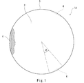
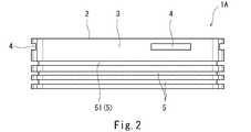
- FIG. 1 is a plan view of a piston for an internal combustion engine according to an embodiment of the present invention. It is a side view of the piston shown in FIG. It is sectional drawing to which the principal part of the piston shown in FIG. 1 was expanded. It is sectional drawing to which the principal part of the piston of a modification was expanded. It is the experimental result performed in order to confirm the effect by a some partial groove
- the fuel of the internal combustion engine in which the piston 1A is used may be fuel oil such as gasoline or heavy oil, or may be fuel gas such as natural gas or hydrogen.
- the piston 1A has a top surface 2 and a peripheral surface, and a plurality of ring grooves 5 are formed on the peripheral surface.
- piston rings 6 are arranged as shown in FIG.
- the ring groove 5 located on the uppermost side (top surface 2 side) of the ring grooves 5 is the top ring groove 51, and the portion between the top ring groove 51 and the top surface 2 on the peripheral surface of the piston 1 ⁇ / b> A is the top land 3. It is.
- a plurality of (three in the illustrated example) partial grooves 4 are formed in the top land 3 so as to be spaced apart from each other in the circumferential direction.
- the partial grooves 4 are desirably arranged at equal intervals, but may be arranged at unequal intervals.
- Each partial groove 4 extends in the circumferential direction.
- the number of partial grooves 4 may be two or four or more.
- each partial groove 4 is configured so that the depth continuously decreases from the center toward both ends.
- the sectional shape of each partial groove 4 is a rectangular shape having side surfaces and a bottom surface that are parallel to each other.
- the sectional shape of each partial groove 4 may be, for example, a triangular shape in which the upper side surface is flat and the lower side surface is inclined like the combustion engine piston 1B of the modification shown in FIG.
- each partial groove 4 is configured such that the bottom of the partial groove 4 extends linearly in a direction perpendicular to the radial direction of the top land 3.
- the bottom of each partial groove 4 may be curved in a convex shape or a concave shape. Or when the bottom of each partial groove
- the depth of both ends of each partial groove 4 is zero, in other words, the depth of the partial groove 4 is continuously shallow from the center to zero toward both ends.
- the depths at both ends of each partial groove 4 are not necessarily zero, and a slight step may be formed at both ends of each partial groove 4.
- the occupation angle ⁇ of each partial groove 4 is not particularly limited, but is, for example, 15 to 45 degrees.
- the number of partial grooves 4 is preferably 3 or more.
- the inventors of the present invention use a piston 1A of the present embodiment in which three partial grooves 4 are formed in the top land 3 in an internal combustion engine using natural gas as fuel.
- the THC (Total Hydro Carbon) concentration in the exhaust gas was measured using a reference piston in which the partial groove 4 was not formed in the topland 3 (that is, the top land of the reference piston was a cylindrical shape without irregularities).
- the reference piston had a THC concentration of 580 ppm
- the piston 1A of the present embodiment had a THC concentration of 450 ppm. This experiment revealed that the THC concentration was reduced by 130 ppm by the partial groove 4.
- the self-ignition phenomenon (knocking) derived from the lubricating oil is reduced by making the lubricating oil difficult to burn.
- a pressure wave is generated, and when the pressure wave collides with the cylinder wall surface 7, a knocking sound may be generated and the temperature boundary layer near the wall surface may be destroyed. This can suppress a self-ignition phenomenon that may cause various troubles, and can improve the quietness and reliability of the internal combustion engine.
- each partial groove 4 since the bottom of each partial groove 4 extends linearly in a direction perpendicular to the radial direction of the top land 3, the partial groove 4 can be formed at low cost.
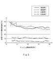
- FIG. 5 shows the results of experiments conducted to confirm the effect of the plurality of partial grooves 4.
- a solid line and a broken line in FIG. 5 represent Examples 1 and 2 in which a plurality of partial grooves 4 are formed in the top land 3, respectively.
- a one-dot broken line and a two-dot broken line in FIG. Comparative Examples 1 and 2 in which a continuous annular groove is formed are shown.
- FIG. 5 shows how much the THC concentration in the exhaust gas was reduced in Examples 1 and 2 and Comparative Examples 1 and 2 as the engine operation time passed with respect to the reference piston having no partial groove and annular groove in the top land described above. Indicate.
- each partial groove 4 having a bottom extending linearly in a direction orthogonal to the radial direction of the top land 3 are formed.
- the occupation angle ⁇ of each partial groove 4 is 30 degrees, and the total sum is 90 degrees.
- the central depth (maximum depth) of each partial groove 4 is about 3/100 with respect to the diameter of the top land 3.
- the number of partial grooves 4 is changed from three to six as compared with the first embodiment. Therefore, in Example 2, the total sum of the occupation angles ⁇ of the partial grooves 4 is 180 degrees.
- the depth of the annular groove is about 1/300 with respect to the diameter of the top land 3.
- the depth of the annular groove is about 1/150 (twice that of Comparative Example 1) with respect to the diameter of the top land 3.
Landscapes
- Engineering & Computer Science (AREA)
- General Engineering & Computer Science (AREA)
- Chemical & Material Sciences (AREA)
- Combustion & Propulsion (AREA)
- Mechanical Engineering (AREA)
- Pistons, Piston Rings, And Cylinders (AREA)
Abstract
Description
3 トップランド
4 部分溝
Claims (3)
- 周方向に延びる複数の部分溝が互いに周方向に離間するように形成されたトップランドを備え、
前記複数の部分溝のそれぞれは、中央から両端に向かって深さが連続的に浅くなるように構成されている、内燃機関用ピストン。 - 前記複数の部分溝のそれぞれは、当該部分溝の底が前記トップランドの径方向と直交する方向に直線状に延びるように構成されている、請求項1に記載の内燃機関用ピストン。
- 前記複数の部分溝の数は3以上であり、
前記複数の部分溝の占有角度の総和は、60度以上270度以下である、請求項1または2に記載の内燃機関用ピストン。
Priority Applications (3)
| Application Number | Priority Date | Filing Date | Title |
|---|---|---|---|
| JP2017559160A JPWO2017115711A1 (ja) | 2015-12-28 | 2016-12-22 | 内燃機関用ピストン |
| US16/066,864 US20180372021A1 (en) | 2015-12-28 | 2016-12-22 | Piston of internal combustion engine |
| EP16881686.6A EP3399176B1 (en) | 2015-12-28 | 2016-12-22 | Piston of internal combustion engine |
Applications Claiming Priority (2)
| Application Number | Priority Date | Filing Date | Title |
|---|---|---|---|
| JP2015256001 | 2015-12-28 | ||
| JP2015-256001 | 2015-12-28 |
Publications (1)
| Publication Number | Publication Date |
|---|---|
| WO2017115711A1 true WO2017115711A1 (ja) | 2017-07-06 |
Family
ID=59227363
Family Applications (1)
| Application Number | Title | Priority Date | Filing Date |
|---|---|---|---|
| PCT/JP2016/088314 Ceased WO2017115711A1 (ja) | 2015-12-28 | 2016-12-22 | 内燃機関用ピストン |
Country Status (4)
| Country | Link |
|---|---|
| US (1) | US20180372021A1 (ja) |
| EP (1) | EP3399176B1 (ja) |
| JP (1) | JPWO2017115711A1 (ja) |
| WO (1) | WO2017115711A1 (ja) |
Cited By (1)
| Publication number | Priority date | Publication date | Assignee | Title |
|---|---|---|---|---|
| JP7616310B1 (ja) | 2023-09-28 | 2025-01-17 | いすゞ自動車株式会社 | 内燃機関 |
Citations (4)
| Publication number | Priority date | Publication date | Assignee | Title |
|---|---|---|---|---|
| JPS61190153A (ja) * | 1985-02-19 | 1986-08-23 | Yanmar Diesel Engine Co Ltd | 内燃機関のピストン |
| JPH0383346U (ja) * | 1989-12-18 | 1991-08-23 | ||
| JPH0583346U (ja) | 1992-04-10 | 1993-11-12 | 株式会社ユニシアジェックス | 内燃機関用ピストン |
| JP2010530051A (ja) * | 2007-06-15 | 2010-09-02 | フェデラル−モーグル コーポレイション | ピストンおよびピストンを用いた内燃エンジン、および当該ピストンの製造方法 |
Family Cites Families (13)
| Publication number | Priority date | Publication date | Assignee | Title |
|---|---|---|---|---|
| US1673775A (en) * | 1927-01-17 | 1928-06-12 | Maxmoor Corp | Antidetonation piston-head formation for internal-combustion engines |
| US1710011A (en) * | 1929-02-08 | 1929-04-23 | Charles S Burnett | Piston |
| US1889387A (en) * | 1931-05-04 | 1932-11-29 | Frederick W Kramer | Piston for internal combustion engines |
| US2662514A (en) * | 1952-02-25 | 1953-12-15 | Jr Albert G Bodine | Detonation suppression piston for internal-combustion engines |
| US2662517A (en) * | 1952-03-01 | 1953-12-15 | Jr Albert G Bodine | Piston for internal-combustion engines having acoustic detonation suppression means |
| US3463057A (en) * | 1967-03-23 | 1969-08-26 | Int Harvester Co | Arrangement of cylinder and piston in engine |
| DE3338216C1 (de) * | 1983-10-21 | 1984-10-18 | Daimler-Benz Ag, 7000 Stuttgart | Gemischverdichtende Brennkraftmaschine |
| US20010048199A1 (en) * | 1997-08-25 | 2001-12-06 | Evans John W. | Piston assembly with piston ring support and sealing member |
| US6557514B1 (en) * | 2001-10-23 | 2003-05-06 | Federal-Mogul World Wide, Inc. | Closed gallery monobloc piston having oil drainage groove |
| KR20050026170A (ko) * | 2003-09-09 | 2005-03-15 | 현대자동차주식회사 | 마찰마력 저감용 피스톤 |
| JP2005226522A (ja) * | 2004-02-12 | 2005-08-25 | Riken Corp | 内燃機関のピストン装置 |
| US20160040622A1 (en) * | 2014-08-05 | 2016-02-11 | General Electric Company | Piston assembly for a reciprocating engine |
| US9845765B2 (en) * | 2015-01-12 | 2017-12-19 | General Electric Company | Piston assembly for a reciprocating engine |
-
2016
- 2016-12-22 WO PCT/JP2016/088314 patent/WO2017115711A1/ja not_active Ceased
- 2016-12-22 US US16/066,864 patent/US20180372021A1/en not_active Abandoned
- 2016-12-22 JP JP2017559160A patent/JPWO2017115711A1/ja active Pending
- 2016-12-22 EP EP16881686.6A patent/EP3399176B1/en active Active
Patent Citations (4)
| Publication number | Priority date | Publication date | Assignee | Title |
|---|---|---|---|---|
| JPS61190153A (ja) * | 1985-02-19 | 1986-08-23 | Yanmar Diesel Engine Co Ltd | 内燃機関のピストン |
| JPH0383346U (ja) * | 1989-12-18 | 1991-08-23 | ||
| JPH0583346U (ja) | 1992-04-10 | 1993-11-12 | 株式会社ユニシアジェックス | 内燃機関用ピストン |
| JP2010530051A (ja) * | 2007-06-15 | 2010-09-02 | フェデラル−モーグル コーポレイション | ピストンおよびピストンを用いた内燃エンジン、および当該ピストンの製造方法 |
Non-Patent Citations (1)
| Title |
|---|
| See also references of EP3399176A4 |
Cited By (1)
| Publication number | Priority date | Publication date | Assignee | Title |
|---|---|---|---|---|
| JP7616310B1 (ja) | 2023-09-28 | 2025-01-17 | いすゞ自動車株式会社 | 内燃機関 |
Also Published As
| Publication number | Publication date |
|---|---|
| EP3399176A1 (en) | 2018-11-07 |
| EP3399176B1 (en) | 2022-04-27 |
| US20180372021A1 (en) | 2018-12-27 |
| EP3399176A4 (en) | 2019-07-24 |
| JPWO2017115711A1 (ja) | 2018-10-18 |
Similar Documents
| Publication | Publication Date | Title |
|---|---|---|
| US9822702B2 (en) | Carbon scraper | |
| US20170321625A1 (en) | Piston assembly for an engine | |
| JP2005069289A (ja) | スペーサエキスパンダ | |
| CN110291313B (zh) | 晃动受抑制的活塞环 | |
| JP2018523072A (ja) | プロファイル部を有するコンプレッションリング | |
| KR102077376B1 (ko) | 4행정 내연 엔진 및 4행정 내연 엔진용 피스톤 | |
| JP6314015B2 (ja) | ピストンとピストンリングの組合せ | |
| WO2017115711A1 (ja) | 内燃機関用ピストン | |
| US20170321624A1 (en) | Piston for an engine | |
| JP2013137080A (ja) | ピストンリング | |
| CN107923299B (zh) | 用于内燃机的活塞 | |
| JP2007247420A (ja) | 副室式内燃機関 | |
| US8069833B2 (en) | Reciprocating engine | |
| JP6514216B2 (ja) | ピストンリング溝、特にコンプレッション溝を有するピストン | |
| CN112901364B (zh) | 用于发动机的活塞 | |
| JP6528720B2 (ja) | ピストン | |
| JP6385700B2 (ja) | オイルリング | |
| JP5644228B2 (ja) | エンジンの燃焼室構造 | |
| JP5932739B2 (ja) | 内燃機関のシリンダブロック | |
| JP6393823B1 (ja) | ガスエンジンの燃焼室構造 | |
| JP6410630B2 (ja) | シリンダヘッド、および、エンジン | |
| JP2007064133A (ja) | ピストン構造 | |
| JP2014009620A (ja) | 内燃機関用ピストンリング | |
| JP6654917B2 (ja) | ピストン | |
| JP2025152625A (ja) | コンプレッションリング |
Legal Events
| Date | Code | Title | Description |
|---|---|---|---|
| 121 | Ep: the epo has been informed by wipo that ep was designated in this application |
Ref document number: 16881686 Country of ref document: EP Kind code of ref document: A1 |
|
| ENP | Entry into the national phase |
Ref document number: 2017559160 Country of ref document: JP Kind code of ref document: A |
|
| NENP | Non-entry into the national phase |
Ref country code: DE |
|
| WWE | Wipo information: entry into national phase |
Ref document number: 2016881686 Country of ref document: EP |
|
| ENP | Entry into the national phase |
Ref document number: 2016881686 Country of ref document: EP Effective date: 20180730 |