WO2017115817A1 - ガス化炉 - Google Patents
ガス化炉 Download PDFInfo
- Publication number
- WO2017115817A1 WO2017115817A1 PCT/JP2016/088980 JP2016088980W WO2017115817A1 WO 2017115817 A1 WO2017115817 A1 WO 2017115817A1 JP 2016088980 W JP2016088980 W JP 2016088980W WO 2017115817 A1 WO2017115817 A1 WO 2017115817A1
- Authority
- WO
- WIPO (PCT)
- Prior art keywords
- shaft
- oxidant
- oxidant supply
- pipe
- supply pipe
- Prior art date
- Legal status (The legal status is an assumption and is not a legal conclusion. Google has not performed a legal analysis and makes no representation as to the accuracy of the status listed.)
- Ceased
Links
Images





Classifications
-
- C—CHEMISTRY; METALLURGY
- C10—PETROLEUM, GAS OR COKE INDUSTRIES; TECHNICAL GASES CONTAINING CARBON MONOXIDE; FUELS; LUBRICANTS; PEAT
- C10J—PRODUCTION OF PRODUCER GAS, WATER-GAS, SYNTHESIS GAS FROM SOLID CARBONACEOUS MATERIAL, OR MIXTURES CONTAINING THESE GASES; CARBURETTING AIR OR OTHER GASES
- C10J3/00—Production of combustible gases containing carbon monoxide from solid carbonaceous fuels
- C10J3/02—Fixed-bed gasification of lump fuel
- C10J3/20—Apparatus; Plants
- C10J3/34—Grates; Mechanical ash-removing devices
- C10J3/36—Fixed grates
- C10J3/38—Fixed grates with stirring beams
-
- B—PERFORMING OPERATIONS; TRANSPORTING
- B09—DISPOSAL OF SOLID WASTE; RECLAMATION OF CONTAMINATED SOIL
- B09B—DISPOSAL OF SOLID WASTE NOT OTHERWISE PROVIDED FOR
- B09B3/00—Destroying solid waste or transforming solid waste into something useful or harmless
- B09B3/70—Chemical treatment, e.g. pH adjustment or oxidation
-
- C—CHEMISTRY; METALLURGY
- C10—PETROLEUM, GAS OR COKE INDUSTRIES; TECHNICAL GASES CONTAINING CARBON MONOXIDE; FUELS; LUBRICANTS; PEAT
- C10J—PRODUCTION OF PRODUCER GAS, WATER-GAS, SYNTHESIS GAS FROM SOLID CARBONACEOUS MATERIAL, OR MIXTURES CONTAINING THESE GASES; CARBURETTING AIR OR OTHER GASES
- C10J3/00—Production of combustible gases containing carbon monoxide from solid carbonaceous fuels
- C10J3/02—Fixed-bed gasification of lump fuel
-
- C—CHEMISTRY; METALLURGY
- C10—PETROLEUM, GAS OR COKE INDUSTRIES; TECHNICAL GASES CONTAINING CARBON MONOXIDE; FUELS; LUBRICANTS; PEAT
- C10J—PRODUCTION OF PRODUCER GAS, WATER-GAS, SYNTHESIS GAS FROM SOLID CARBONACEOUS MATERIAL, OR MIXTURES CONTAINING THESE GASES; CARBURETTING AIR OR OTHER GASES
- C10J3/00—Production of combustible gases containing carbon monoxide from solid carbonaceous fuels
- C10J3/02—Fixed-bed gasification of lump fuel
- C10J3/20—Apparatus; Plants
- C10J3/32—Devices for distributing fuel evenly over the bed or for stirring up the fuel bed
-
- C—CHEMISTRY; METALLURGY
- C10—PETROLEUM, GAS OR COKE INDUSTRIES; TECHNICAL GASES CONTAINING CARBON MONOXIDE; FUELS; LUBRICANTS; PEAT
- C10J—PRODUCTION OF PRODUCER GAS, WATER-GAS, SYNTHESIS GAS FROM SOLID CARBONACEOUS MATERIAL, OR MIXTURES CONTAINING THESE GASES; CARBURETTING AIR OR OTHER GASES
- C10J3/00—Production of combustible gases containing carbon monoxide from solid carbonaceous fuels
- C10J3/72—Other features
- C10J3/74—Construction of shells or jackets
- C10J3/76—Water jackets; Steam boiler-jackets
-
- C—CHEMISTRY; METALLURGY
- C10—PETROLEUM, GAS OR COKE INDUSTRIES; TECHNICAL GASES CONTAINING CARBON MONOXIDE; FUELS; LUBRICANTS; PEAT
- C10J—PRODUCTION OF PRODUCER GAS, WATER-GAS, SYNTHESIS GAS FROM SOLID CARBONACEOUS MATERIAL, OR MIXTURES CONTAINING THESE GASES; CARBURETTING AIR OR OTHER GASES
- C10J2200/00—Details of gasification apparatus
- C10J2200/15—Details of feeding means
-
- C—CHEMISTRY; METALLURGY
- C10—PETROLEUM, GAS OR COKE INDUSTRIES; TECHNICAL GASES CONTAINING CARBON MONOXIDE; FUELS; LUBRICANTS; PEAT
- C10J—PRODUCTION OF PRODUCER GAS, WATER-GAS, SYNTHESIS GAS FROM SOLID CARBONACEOUS MATERIAL, OR MIXTURES CONTAINING THESE GASES; CARBURETTING AIR OR OTHER GASES
- C10J2200/00—Details of gasification apparatus
- C10J2200/15—Details of feeding means
- C10J2200/152—Nozzles or lances for introducing gas, liquids or suspensions
-
- C—CHEMISTRY; METALLURGY
- C10—PETROLEUM, GAS OR COKE INDUSTRIES; TECHNICAL GASES CONTAINING CARBON MONOXIDE; FUELS; LUBRICANTS; PEAT
- C10J—PRODUCTION OF PRODUCER GAS, WATER-GAS, SYNTHESIS GAS FROM SOLID CARBONACEOUS MATERIAL, OR MIXTURES CONTAINING THESE GASES; CARBURETTING AIR OR OTHER GASES
- C10J2300/00—Details of gasification processes
- C10J2300/09—Details of the feed, e.g. feeding of spent catalyst, inert gas or halogens
- C10J2300/0913—Carbonaceous raw material
- C10J2300/0916—Biomass
-
- C—CHEMISTRY; METALLURGY
- C10—PETROLEUM, GAS OR COKE INDUSTRIES; TECHNICAL GASES CONTAINING CARBON MONOXIDE; FUELS; LUBRICANTS; PEAT
- C10J—PRODUCTION OF PRODUCER GAS, WATER-GAS, SYNTHESIS GAS FROM SOLID CARBONACEOUS MATERIAL, OR MIXTURES CONTAINING THESE GASES; CARBURETTING AIR OR OTHER GASES
- C10J2300/00—Details of gasification processes
- C10J2300/09—Details of the feed, e.g. feeding of spent catalyst, inert gas or halogens
- C10J2300/0953—Gasifying agents
- C10J2300/0959—Oxygen
-
- C—CHEMISTRY; METALLURGY
- C10—PETROLEUM, GAS OR COKE INDUSTRIES; TECHNICAL GASES CONTAINING CARBON MONOXIDE; FUELS; LUBRICANTS; PEAT
- C10J—PRODUCTION OF PRODUCER GAS, WATER-GAS, SYNTHESIS GAS FROM SOLID CARBONACEOUS MATERIAL, OR MIXTURES CONTAINING THESE GASES; CARBURETTING AIR OR OTHER GASES
- C10J2300/00—Details of gasification processes
- C10J2300/18—Details of the gasification process, e.g. loops, autothermal operation
- C10J2300/1861—Heat exchange between at least two process streams
- C10J2300/1892—Heat exchange between at least two process streams with one stream being water/steam
-
- F—MECHANICAL ENGINEERING; LIGHTING; HEATING; WEAPONS; BLASTING
- F23—COMBUSTION APPARATUS; COMBUSTION PROCESSES
- F23G—CREMATION FURNACES; CONSUMING WASTE PRODUCTS BY COMBUSTION
- F23G5/00—Incineration of waste; Incinerator constructions; Details, accessories or control therefor
- F23G5/24—Incineration of waste; Incinerator constructions; Details, accessories or control therefor having a vertical, substantially cylindrical, combustion chamber
-
- Y—GENERAL TAGGING OF NEW TECHNOLOGICAL DEVELOPMENTS; GENERAL TAGGING OF CROSS-SECTIONAL TECHNOLOGIES SPANNING OVER SEVERAL SECTIONS OF THE IPC; TECHNICAL SUBJECTS COVERED BY FORMER USPC CROSS-REFERENCE ART COLLECTIONS [XRACs] AND DIGESTS
- Y02—TECHNOLOGIES OR APPLICATIONS FOR MITIGATION OR ADAPTATION AGAINST CLIMATE CHANGE
- Y02P—CLIMATE CHANGE MITIGATION TECHNOLOGIES IN THE PRODUCTION OR PROCESSING OF GOODS
- Y02P20/00—Technologies relating to chemical industry
- Y02P20/141—Feedstock
- Y02P20/145—Feedstock the feedstock being materials of biological origin
Definitions
- the present invention relates to a gasification furnace and a gasification system for gasifying biomass resources.
- biomass resources biological resources such as crushed building waste materials
- biomass resources are put into a gasification furnace and ignited.
- the biomass resources are dry-distilled with this heat, and organic substances are pyrolyzed and gasified to produce fuel gas containing H 2 , CH 4 , CO, etc. To do.
- a configuration for supplying the oxidant a configuration for supplying from a supply port provided on the inner wall of the gasification furnace containing the biomass resources, or a rotation shaft provided with a stirring member in the gasification furnace is provided.
- tip (lower end) of this is known (patent document 3).
- the reaction between the oxidizing agent and the biomass resource is limited to the periphery of the supplying unit, and there is a problem that the efficiency is poor. .
- an object of the present invention is to provide a gasification furnace capable of efficiently gasifying biomass resources.
- the gasification furnace of the present invention comprises: A furnace body having a cylindrical containing portion for containing biomass resources; An oxidant supply unit for supplying an oxidant into the furnace body; A shaft that extends in the vertical direction in the housing and encloses an oxidant supply path through which the oxidant passes; A tubular member projecting from the shaft toward the inner wall of the housing portion, the oxidant supply port opening on the outer surface in contact with the biomass resource in the housing portion and the oxidant supply path of the shaft; An oxidant supply pipe containing an oxidant flow path communicating therewith, and A drive unit for rotating the oxidant supply pipe in the housing unit by rotating the shaft about the vertical direction in the housing unit as a rotation axis; Is provided.
- the shaft may include a refrigerant flow path
- the oxidant supply pipe may include a refrigerant flow path communicating with the flow path on the shaft side.
- the gasification furnace is an upper portion protruding from the shaft toward the inner wall of the accommodating portion at a height that matches the target when the biomass resource is charged from the upper portion of the accommodating portion and deposited to a target height.
- a scraper may be provided.
- the gasification furnace is provided with a partition portion that has a plurality of openings that vertically divide the housing portion and penetrates in the up-down direction, and is in contact with or close to the upper surface of the partition portion from the shaft to the housing portion.
- a lower scraper that protrudes toward the inner wall may be provided.
- the gasification furnace is provided with a partition part having a plurality of holes penetrating the storage part in the vertical direction, the storage part above the partition part being a first gasification chamber, and from the partition part A second gasification chamber may be provided in the lower accommodating portion.
- the shaft and the oxidant supply pipe may be provided in each of the first gasification chamber and the second gasification chamber.
- the shaft is provided across the first gasification chamber and the second gasification chamber, and the oxidant supply pipe includes the first gasification chamber and the second gasification chamber. It may be provided in each of these.
- the shaft has a first oxidant supply path for supplying an oxidant to the oxidant supply pipe in the first gasification chamber from above, and the oxidation in the second gasification chamber from below.
- the gasification furnace may include a lower scraper that protrudes from the shaft toward the inner wall of the housing portion in contact with or close to the upper surface of the partition portion.
- a gasifier capable of efficiently gasifying biomass resources can be provided.
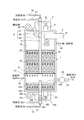
- FIG. 1 is an explanatory diagram of a gasification furnace according to the first embodiment.
- FIG. 2 is a diagram illustrating the configuration of the shaft.
- FIG. 5A is a diagram showing a cross section passing through the center of rotation parallel to the front surface shown in FIG.
- FIG. 5B is a diagram showing a cross section passing through the center of rotation parallel to the side surface shown in FIG. 6 is a cross-sectional view of the upper scraper along line D in FIG.
- FIG. 7 is a cross-sectional view taken along line C in FIG.
- FIG. 8 is a cross-sectional view taken along line E in FIG. FIG.
- FIG. 9 is a cross-sectional view of the lower scraper taken along line F of FIG.
- FIG. 10 is a diagram illustrating a modification of the shaft.
- FIG. 11 is an explanatory diagram of a gasification furnace according to the second embodiment.
- FIG. 12 is an explanatory diagram of a gasification furnace according to the third embodiment.
- FIG. 13 is an explanatory diagram of a gasification furnace according to the fourth embodiment.
- the gasification furnace according to Embodiment 1 is a unit for using biomass resources as raw materials and gasifying these raw materials by dry distillation.
- the gasification furnace includes a furnace body 1, a shaft 3, a raw material charging unit 4, a drive unit 5, an oxidant supply unit 6, a punching plate 13, a lower scraper 21, an oxidant supply pipe 22, an upper scraper 23, and a blower 12. Yes.
- the furnace main body 1 has a cylindrical accommodating portion 19 that accommodates a raw material therein, and has a water cooling jacket 18 between the outer wall and the inner wall.
- the water cooling jacket 18 introduces cooling water as a refrigerant from the refrigerant introduction part 11 provided in the upper part, circulates through the wall of the furnace main body 1 to cool the furnace main body, and discharges the cooled refrigerant from the refrigerant discharge part 15. .
- the shaft 3 extends in the vertical direction in the accommodating portion 19 and includes an oxidant supply path through which an oxidant passes as will be described later.
- the raw material charging unit 4 is a device for charging raw materials such as chips and pellets into the storage unit 19 in the furnace body 1.
- the raw material input part 4 inputs the raw material supplied from supply systems, such as a chain conveyor not shown, a bucket elevator, and a screw conveyor, into the accommodating part 19 with a screw feeder, for example.
- the raw material charging unit 4 includes an electric heater 41 that ignites the raw material.
- the driving unit 5 includes an electric motor 51 as a driving source and a coupling mechanism 52 such as a gear for transmitting the driving force of the electric motor 51 to the shaft 3 and rotationally drives the shaft 3 with the vertical direction as a rotation axis.
- a coupling mechanism 52 such as a gear for transmitting the driving force of the electric motor 51 to the shaft 3 and rotationally drives the shaft 3 with the vertical direction as a rotation axis.
- the oxidant supply unit 6 includes a blower 61, a duct 62, and a connection part 63.
- the connection part 63 communicates with the oxidant supply path of the shaft 3 as described later, and air as an oxidant is blown by the blower 61.
- An oxidant is supplied into the accommodating portion 19 through the duct 62, the connecting portion 63, and the shaft 3.
- the punching plate 13 is a partition part which partitions the accommodating part 19 up and down and has a plurality of openings penetrating vertically.
- the punching plate 13 is configured such that the size of the opening is set smaller than the size of the raw material at the time of charging so that the raw material charged in the accommodating portion 19 can be loaded, and the raw material carbonized and dropped is dropped. It has become.
- the punching plate 13 of the first embodiment is a so-called punching metal, but is not limited thereto, and may be a mesh or a lattice.
- the lower scraper 21 is configured to protrude in the horizontal direction from the shaft 3 toward the inner wall of the accommodating portion 19 while being in contact with or close to the upper surface of the punching plate 13.
- the close state means that the gap between the lower end of the lower scraper 21 and the punching plate 13 is close to the raw material size or larger than the raw material size so that the raw material on the punching plate 13 can be moved. It is in a state of approaching to become smaller.
- the oxidant supply pipe 22 is a tubular member that protrudes horizontally from the shaft 3 toward the inner wall of the housing part 19, and is an oxidant supply port that opens to the outer surface in contact with the raw material in the housing part and the oxidant of the shaft.
- An oxidant flow path communicating with the supply path is included.
- the upper scraper 23 is configured to project horizontally from the shaft 3 toward the inner wall of the housing portion 19 at a height that matches the target when the raw material is charged from the upper portion of the housing portion 19 and deposited to a target height. It has become.
- the blower 12 is connected to the space below the punching plate 13 of the accommodating portion 19 on the intake side, sucks out the fuel gas gasified in the accommodating portion 19 and sends it to the demand side such as a gas turbine via the pipe 14. Yes.
- the raw material is charged into the accommodating portion 19 by the raw material charging portion 4, the raw material is deposited on the punching plate 13, and the shaft 3 is driven to rotate so that the oxidizing agent supply pipe 22 is accommodated in the accommodating portion 19.
- the raw material is dry-distilled in a state where it is horizontally swirled inside, and the organic matter is gasified to produce fuel gas, which is sent to the demand side.
- the gasification furnace of the first embodiment supplies the oxidant while rotating the oxidant supply pipe 22 in the horizontal direction in the accommodating portion 19, and thus the reaction occurs in a wide range in the horizontal direction in the accommodating portion 19. Since the thermal decomposition accompanying this occurs in a wide range, gasification can be performed efficiently.
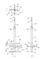
- FIG. 2A and 2B are diagrams showing the configuration of the shaft 3, in which FIG. 2A is a front view of the shaft 3, FIG. 2B is a side view, and FIG. 2C is a cross-sectional view along AA.
- FIG. 3 is an exploded perspective view showing a part of the shaft 3.
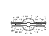
- the shaft 3 has a cooling water forward pipe 34 as a refrigerant flow path at the center, and an upper shaft 33 is fitted on the forward pipe 34, and the outer peripheral surface of the forward pipe 34. And a space between the inner peripheral surface of the upper shaft 33 is a cooling water return pipe 332 which is a refrigerant flow path.
- the lower shaft 31 is connected below the upper shaft 33.
- the lower shaft 31 has an outward tube 34 in the center, and has an outer shell 317 concentrically with the forward tube 34.
- the space between the outer peripheral surface of the forward tube 34 and the inner peripheral surface of the outer shell 317 is divided into four vertically. It is divided.
- the lower shaft 31 divides the space between the outer peripheral surface of the forward tube 34 and the inner peripheral surface of the outer shell 317 into four by the partition plates 313 to 316 in a cross section orthogonal to the rotation axis.
- a pair of spaces that are point-symmetrical with respect to the forward pipe 34 as a center is used as a cooling water return pipe 319 that is a refrigerant flow path.
- the pair of spaces serve as an oxidant supply path 318.
- the return pipes 319 and 319 are closed by lid portions 328 and 328 at portions outside the upper shaft 33. Further, the oxidant supply paths 318 and 318 are closed by lid portions 329 and 329 on the inner side of the upper shaft 33. That is, the return pipe 332 of the upper shaft 33 communicates with the return pipe 319 in a region where the lid portions 329 and 329 of the lower shaft 31 are not provided.
- the outer shell 317 of the lower shaft 31 has a structure in which a circular pipe is divided into four parts and connected between the partition plates 313 to 316.
- outer shells 317 extend upward from the lower end of the upper shaft 33, form a space with the outer surface of the upper shaft 33, and are closed at the upper end by a lid portion 312. In this space, the outer peripheral surface and the inner peripheral surface are penetrated in the upper part of the outer shell 317 facing the oxidant supply path 318 sandwiched between the partition plates 314 and 315 and the oxidant supply path 318 sandwiched between the partition plates 316 and 313.
- Hole 311 is provided.
- the hole 311 serving as an oxidant supply port communicates with the oxidant supply paths 318 and 318 in a region where the lid portions 329 and 329 of the lower shaft 31 are not provided.
- a cap-shaped connecting portion 169 is connected to the upper end portion of the outgoing tube 34, and the outgoing tube 34 can rotate with respect to the connecting portion 169, and the connecting portion 169 and the outgoing tube 34.
- the connecting portion 169 is supplied with cooling water from a cold heat source (not shown) via the forward pipe 16 and supplies the cooling water to the forward pipe 34 of the shaft 3.
- connection pipe 35 recirculates the cooling water circulated through the upper scraper 23, the oxidant supply pipe 22, and the lower scraper 21 to the cold heat source side via the return pipe 17.
- the shaft 3 is connectably connected to the connecting portion 169 and the connecting pipe 35 as described above, the shaft 3 is connected to the forward pipe 34 and the return pipes 319 and 332 as a refrigerant flow path even if driven.
- the refrigerant can be circulated.
- a connecting portion 63 of the oxidant supply unit 6 is provided so as to cover the periphery of the hole 311 of the lower shaft 31, and the oxidant is connected from the blower 61 through the duct 62 to the connecting portion.
- the gas is sent into the gas outlet 63, it is supplied to the oxidant supply passage 318 through the holes 311 and 311.
- the shaft 3 is rotatably connected to the connection portion 63, the oxidant can be supplied to the oxidant supply path 318 even when driven to rotate.
- the oxidant supply pipe 22 is provided with a plurality of oxidant supply pipes 22 radially from the lower shaft 31 at equal intervals with the other oxidant supply pipes 22 adjacent to each other. .
- four oxidant supply pipes 22 are provided radially.
- two oxidant supply pipes 22 are provided on a straight line with the lower shaft 31 interposed therebetween, and two other oxidant supply pipes 22 are provided on the straight line orthogonal to the straight line with the lower shaft 31 interposed therebetween. It has been.
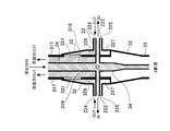
- FIG. 4 is a cross-sectional view of the oxidant supply pipe 22 along line B shown in FIG.
- the oxidant supply pipe 22 has a cooling water forward pipe 222 that is a refrigerant flow path at the center, and an outer pipe 223 whose cross section is concentric with the forward pipe 222.
- the base end portion of the oxidant supply pipe 22 is connected to the shaft 3, and the tip end portion is closed by a lid portion (not shown).
- the oxidant supply pipe 22 divides the space between the outer peripheral surface of the forward pipe 222 and the inner peripheral surface of the outer pipe 223 into two vertically by a partition plate 226.
- the upper divided space is a refrigerant return pipe 224 and the lower space is an oxidant flow path 225.
- the outer tube 223 that forms the oxidant flow path has an oxidant supply port 227 that opens to the outer surface in contact with the raw material at a predetermined position in the longitudinal direction and communicates with the internal oxidant flow path 225.
- the oxidant supply pipe 22 according to the first embodiment has two oxidant supply ports 227 at nine places at substantially equal intervals in the longitudinal direction. As described above, the oxidant supply pipe 22 supplies the oxidant from each of the plurality of oxidant supply ports 227 provided in the longitudinal direction.
- the forward pipe 222 is connected to the return pipe 224 in the vicinity of the distal end of the oxidant supply pipe 22, and the refrigerant supplied to the distal end portion by the forward pipe 222 is folded back to the return pipe 224 to return the return pipe in the lower shaft 31. Reflux to 319.
- stirring blades 221 are erected on the upper portion of each oxidant supply pipe 22 at a predetermined interval in the longitudinal direction of the oxidant supply pipe 22. Since the position of the stirring blade 221 in the longitudinal direction of the oxidant supply pipe 22 is different for each oxidant supply pipe 22, the stirring blade 221 of each oxidant supply pipe 22 can be stirred at a different position in the longitudinal direction. The inside of the part 19 can be stirred thoroughly.
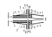
- FIG. 5A is a diagram showing a cross section passing through the center of rotation parallel to the front surface shown in FIG. 2A
- FIG. 5B shows a cross section passing through the center of rotation parallel to the side surface shown in FIG. 2B.
- FIG. As shown in FIGS. 5A and 5B, the forward pipe 34 of the lower shaft 31 and the forward pipe 222 of each oxidant supply pipe 22 are connected. Further, an outer ring member 32 is provided around a connection portion between the lower shaft 31 and the oxidant supply pipe 22, and a space is formed between the outer surface of the lower shaft 31 and the inner surface of the outer ring member 32.
- This space is partitioned by an unillustrated partition plate into an upper space 326 communicating with the refrigerant return pipe 224 of the oxidant supply pipe 22 and a lower space 327 communicating with the oxidant flow path 225 of the oxidant supply pipe 22. It has been.
- the outer shell 317 of the lower shaft 31 is provided with a communication hole 321 that connects the cooling water return pipe 319 and the upper space 326 located outside the return pipe 319. Further, the upper space 326 and the refrigerant flow path 224 of the oxidant supply pipe 22 communicate with each other.
- the refrigerant sent from the forward pipe 34 of the lower shaft 31 to the distal end portion of each oxidant supply pipe 22 via the forward pipe 222 of each oxidant supply pipe 22 passes through each oxidant supply pipe 22. Fold back to return tube 224 at the tip. Then, the refrigerant returned to the return pipe 224 of the oxidant supply pipe 22 returns to the return pipe 319 of the lower shaft 31 through the upper space 326 and the communication hole 321 of the outer shell 317.
- the outer shell 317 of the lower shaft 31 is provided with a communication hole 322 that communicates the oxidant supply path 318 and the lower space 327 in the outer ring member 32. Further, the lower space 327 communicates with the oxidant flow path 225 of the oxidant supply pipe 22.
- the air as the oxidant supplied to the oxidant supply path 318 of the lower shaft 31 is supplied to the lower space 327 through the communication hole 322.
- the air as the oxidant is sent from the lower space 327 to the oxidant flow path 225 of the oxidant supply pipe 22 and supplied to the raw material from the oxidant supply port 227 provided in the oxidant flow path 225.
- the refrigerant flow path 224 communicates with the upper space 326, and the refrigerant returned to the refrigerant flow path 224 is introduced into the upper space 326.
- the refrigerant in the upper space 326 returns to the refrigerant flow path 319 of the lower shaft 31 via the communication hole 321 shown in FIG. 5A.
- the oxidant flow path 225 of the oxidant supply pipe 22 communicates with the lower space 327. Since the lower space is connected in the circumferential direction, the oxidant introduced into the lower space 327 through the communication hole 322 shown in FIG. 5B is transferred from the lower space 327 shown in FIG. 5A to the oxidant supply pipe 22. To the oxidant flow path 225.
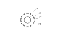
- FIGS. 6 is a cross-sectional view of the upper scraper 23 taken along line D of FIG.
- the upper scraper 23 has a cooling water forward pipe 231 that is a refrigerant flow path in the center, and an outer pipe 232 concentrically with the forward pipe 231 in the cross section of FIG. 6.
- the upper scraper 23 has a space between the outer peripheral surface of the forward pipe 231 and the inner peripheral surface of the outer pipe 232 as a refrigerant return pipe 233, and the forward pipe 231 is opened near the tip of the upper scraper 23 and returned.
- a pipe 233 is connected.
- the base end part of the upper scraper 23 is connected with the shaft 3, and the front-end
- FIG. 7 is a cross-sectional view taken along line C in FIG.
- the refrigerant supplied from the forward pipe 34 in the lower shaft 31 to the forward pipe 231 of the upper scraper 23 is sent to the distal end portion of the upper scraper 23 by the forward pipe 231, and is returned to the return pipe 233 to return to the return pipe in the lower shaft 31. Reflux to 319. As the refrigerant circulates in the forward pipe 231 and the return pipe 233 as described above, the upper scraper 23 is cooled.
- FIGS. 8 is a cross-sectional view taken along line E of FIG. 2
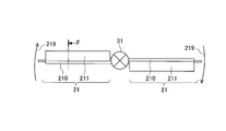
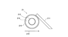
- FIG. 9 is a cross-sectional view of the lower scraper 21 taken along line F of FIG.
- two lower scrapers 21 are provided on a straight line with the lower shaft 31 interposed therebetween.
- the lower scraper 21 is not limited to this, and three or more lower scrapers 21 may be provided radially with the lower shaft 31 as the center.
- the lower scraper 21 has a cooling water forward pipe 213 which is a refrigerant flow path at the center, and an outer pipe 210 concentrically with the forward pipe 213 in the cross section of FIG.
- the lower scraper 21 uses a space between the outer peripheral surface of the forward pipe 213 and the inner peripheral surface of the outer pipe 210 as a refrigerant return pipe 214, and the forward pipe 213 is opened near the tip of the lower scraper 21 and returned.
- the base end part of the lower scraper 21 is connected with the lower shaft 31, and the front-end
- the lower scraper 21 similarly to the upper scraper 23 shown in FIG.
- the forward pipe 213 is connected to the forward pipe 34 of the lower shaft 31, and the return pipe 214 is connected to the return pipe 319 of the lower shaft 31.
- the refrigerant supplied from the forward pipe 34 in the lower shaft 31 to the forward pipe 213 of the lower scraper 21 is sent to the distal end portion of the lower scraper 21 by the forward pipe 213 and is returned to the return pipe 214 to be returned in the lower shaft 31. Reflux to tube 319. As the refrigerant circulates in the forward pipe 213 and the return pipe 214 in this way, the lower scraper 21 is cooled.
- the lower scraper 21 rotates in the arrow 219 direction, that is, in the clockwise direction in FIG. 8 as the lower shaft 31 rotates.
- the lower scraper 21 includes a flat push plate 211 on the front side of the outer tube 210 in this rotational direction.
- the lower scraper 21 is provided at a position where the lower end of the push plate 211 or the lower end of the outer tube 210 is in contact with or close to the upper surface of the punching plate 13.
- the lower scraper 21 provided at this position is rotated and stirred so that the push plate 211 pushes away the raw material, so that the carbonized and finely divided raw material falls through the holes of the punching plate 13.
- the carbonized raw material can be eliminated, and the raw material on the punching plate 13 can be replaced to continuously perform gasification.
- a cold heat source (not shown) supplies cooling water as a refrigerant to the shaft 3 via the forward pipe 16, and circulates in the shaft 3 for cooling.
- the circulating cooling water is discharged from the return pipe 17.
- this cold heat source supplies cooling water to the water cooling jacket 18 of the furnace body 1 through the refrigerant introduction part 11 and circulates in the water cooling jacket 18 to cool it.
- the circulating cooling water is discharged from the refrigerant discharge unit 15.
- the drive unit 5 rotates the shaft 3 by driving the motor 51.
- the upper scraper 23, the oxidant supply pipe 22, and the lower scraper 21 connected to the shaft 3 also rotate within the housing portion 19.
- the oxidant supply unit 6 sends out air as an oxidant by the blower 61 and supplies the air into the shaft 3 through the duct 62 and the connection part 63.
- the air supplied into the shaft 3 is supplied to the oxidant supply pipe 22 via the oxidant supply path 318 and is supplied to the raw material from the oxidant supply port 227 via the oxidant flow path 225.
- the material spreads from the raw material ignited in the raw material charging unit 4, and the whole raw material deposited in the storage unit 19 is ignited. And if oxygen in the accommodating part 19 is consumed, it will be in a dry distillation state.
- the oxidant supply unit 6 supplies an appropriate amount of air so as to maintain this dry distillation state.
- the organic matter in the raw material is pyrolyzed and gasified by this dry distillation, and this gas is sucked into the drive of the blower 12 and supplied to the demand side through the pipe 14 as fuel gas.
- the lower scraper 21 stirs the raw material on the punching plate 13 and discharges the carbonized and finely divided raw material through the holes of the punching plate 13. That is, the space under the punching plate 13 functions as a fuel gas suction chamber and also functions as a receiving portion for the raw material after gasification.
- control is performed so that the raw material accumulated in the storage unit 19 reaches a target height.
- This control may be performed by measuring the amount of raw material deposited by a sensor or the like and controlling the amount of raw material charging unit 4 by a control device. Also good.
- the upper scraper 23 was provided at a position corresponding to the height of the upper scraper. By turning the upper scraper, the piles of the charged raw materials are leveled, and the height of the raw materials becomes uniform.
- the oxidant supply pipe 22 supplies the oxidant while turning in the housing portion 19, so that the oxidation reaction can be appropriately performed in a wide range in the housing portion 19. Gasification can be performed efficiently.
- the upper scraper 23 is provided at a position that matches the target height for depositing the raw material, the height of the deposited raw material can be made uniform, and is covered by the turning of the upper scraper 23 in the accommodating portion 19. Gasification can be appropriately performed over a wide range.
- the lower scraper 21, the oxidant supply pipe 22, and the upper scraper 23 are provided, but the lower scraper 21 and the upper scraper 23 may be omitted.
- the oxidant supply pipe 22 may also serve as the lower scraper 21 or the upper scraper 23.
- the height at which the oxidant supply pipe 22 is installed may be set arbitrarily.
- the height at which the oxidant supply pipe 22 is installed is set according to the raw materials, reaction conditions, the shape of the accommodating portion, and the like.
- the oxidant is supplied from the oxidant supply pipe 22.
- the oxidant flow path is included in the upper scraper 23 or the lower scraper 21, and the oxidant is supplied from the upper scraper 23 or the lower scraper 21. It is good also as a structure which supplies.
- the space between the outer peripheral surface of the oxidant supply path 401 and the inner peripheral surface of the outer pipe 400 is divided into two by a partition plate 409, with the oxidant supply path 401 as the center, and one side is the forward pipe. 402 and the other is a return pipe 403.
- FIG. 10B shows an example in which the inner space of the outer tube 400 is radially divided into eight by the partition plate 408. Of these eight spaces, four are oxidant supply paths 401, two are outgoing pipes 402, and the remaining two are return pipes 403.
- FIG. 10C shows an example in which the inner space of the outer tube 400 is divided into four by a partition plate 408. Of these four spaces, two are oxidant supply paths 401, one is an outgoing pipe 402, and the other is a return pipe 403.
- cross-sectional shape of the shaft is not limited to a circle, but may be other shapes.
- FIGS. 10D to 10F are rectangular.
- the space between the outer peripheral surface of the oxidant supply passage 401 and the inner peripheral surface of the outer tube 410 is divided into two by the partition plate 407, with the oxidant supply passage 401 as the center, and one side is the forward tube. 402 and the other is a return pipe 403.
- FIG. 10E shows an example in which the inner space of the outer tube 410 is divided into four diagonal lines by the partition plate 406. Of these four spaces, two are oxidant supply paths 401, one is an outgoing pipe 402, and the other is a return pipe 403.
- FIG. 10F shows an example in which the inner space of the outer tube 410 is divided into four parts vertically and horizontally by a partition plate 405. Of these four spaces, two are oxidant supply paths 401, one is an outgoing pipe 402, and the other is a return pipe 403.
- the oxidant supply path 401, the forward pipe 402, and the return pipe 403 are preferably arranged symmetrically about the rotation axis as shown in FIGS. 10 (A) to 10 (F).
- FIG. 11 is an explanatory diagram of a gasification furnace according to the second embodiment.
- the gasification furnace according to the second embodiment is different from the first embodiment in that the second gasification chamber is provided below the punching plate 13 and the other components are the same.
- the repetitive explanation is omitted by attaching the same reference numerals.
- the region above the punching plate 13 in the accommodating portion 19 is the first gasification chamber, and the region below the punching plate 13 is the second gasification chamber.
- the shaft 3 is extended to the second gasification chamber below the punching plate 13, and an upper scraper 123 and an oxidant supply pipe 122 are provided in the second gasification chamber.
- the upper scraper 123 has the same configuration as that of the above-described upper scraper 23, and the oxidant supply pipe 122 has the same configuration as that of the above-described oxidant supply pipe 22. Therefore, detailed description of the configuration is omitted.
- the raw material carbonized in the first gasification chamber (hereinafter also simply referred to as carbide) falls from the hole of the punching plate 13.
- a carbon such as CO is generated by dry distillation while supplying air as an oxidant to the carbide deposited in the second gasification chamber.
- the carbide discharged from the first gasification chamber can be reused for further gasification to improve the gasification efficiency.
- the oxidant supply pipe 122 and the upper scraper 123 are provided, but the upper scraper 123 may be omitted.
- a lower scraper may be provided.
- the oxidant is supplied from the oxidant supply pipe 122 in the second gasification chamber.
- the oxidant flow path is included in the upper scraper 123 or the lower scraper, and the oxidant is supplied from the upper scraper 123 or the lower scraper. It is good also as composition to do.
- FIG. 12 is an explanatory diagram of a gasification furnace according to the third embodiment.
- the gasification furnace of the third embodiment is different from the second embodiment in that the refrigerant flow path and the oxidant supply path are independent in the first gasification chamber and the second gasification chamber. Since the configuration is the same, the same elements are denoted by the same reference numerals and the description thereof is omitted.
- region above the punching plate 13 in the accommodating part 19 is a 1st gasification chamber, and the area
- the refrigerant flow path and the oxidant supply path of the second gasification chamber are made different from those of the first gasification chamber, and the oxidant and cooling water for the second gasification chamber are supplied from the lower end of the shaft 3. It is the structure to make.
- the oxidant supply unit 106 blows air for the second gasification chamber with the blower 161 and supplies air to the oxidant supply pipe 122 through the duct 162, the connecting pipe 163, and the shaft 3. Then, the air is supplied from the oxidizing agent supply pipe 122 to the carbide.
- the refrigerant flow path and the oxidant supply path of the second gasification chamber are different from those of the first gasification chamber.
- the second gasification chamber can be set appropriately.
- FIG. 13 is an explanatory diagram of a gasification furnace according to the fourth embodiment. Since the gasification furnace of the fourth embodiment is different from the third embodiment described above in that the first gasification chamber and the second gasification chamber have independent shafts, and other configurations are the same. The same elements are given the same reference numerals and the description thereof is omitted.
- a shaft 103 is provided in the second gasification chamber separately from the shaft 3 of the first gasification chamber, and an upper scraper 123 and an oxidant supply pipe 122 are connected to the shaft 103.
- the drive unit 105 includes an electric motor 151 as a drive source, and a coupling mechanism 152 such as a gear that transmits the driving force of the electric motor 151 to the shaft 103, and rotates the shaft 103 about the vertical direction as a rotation axis.
- the shaft 103 of the second gasification chamber is provided separately from the first gasification chamber, the first gasification chamber and the second gasification chamber can be easily separated. And maintainability is improved.
- the rotation conditions such as the rotation speed of the shaft and the timing for starting the rotation can be appropriately set in the first gasification chamber and the second gasification chamber, respectively.
Landscapes
- Chemical & Material Sciences (AREA)
- Engineering & Computer Science (AREA)
- Combustion & Propulsion (AREA)
- Oil, Petroleum & Natural Gas (AREA)
- Organic Chemistry (AREA)
- Mechanical Engineering (AREA)
- Health & Medical Sciences (AREA)
- Chemical Kinetics & Catalysis (AREA)
- General Chemical & Material Sciences (AREA)
- General Health & Medical Sciences (AREA)
- Toxicology (AREA)
- Environmental & Geological Engineering (AREA)
- Processing Of Solid Wastes (AREA)
- Gasification And Melting Of Waste (AREA)
Abstract
Description
バイオマス資源を収容する円筒状の収容部を有する炉本体と、
前記炉本体内へ酸化剤を供給する酸化剤供給部と、
前記収容部内の鉛直方向に延設され、前記酸化剤を通す酸化剤供給路を内包するシャフトと、
前記シャフトから前記収容部の内壁へ向かって突出した管状の部材であって、前記収容部内の前記バイオマス資源と接する外面に開口した前記酸化剤の供給口と前記シャフトの前記酸化剤供給路とを連通する酸化剤流路を内包する酸化剤供給管と、
前記収容部内の鉛直方向を回転軸として前記シャフトを回転させることにより、前記酸化剤供給管を前記収容部内で旋回させる駆動部と、
を備える。
前記ガス化炉は、前記収容部の上部から前記バイオマス資源を投入し、目標の高さまで堆積させる場合の前記目標に合わせた高さで、前記シャフトから前記収容部の内壁へ向かって突出した上部スクレーパーを備えても良い。
以下、本発明の実施形態について、図面を参照して詳細に説明する。まず、図1を用いて、本発明の実施形態1に係るガス化炉の概要を説明する。
本実施形態1に係るガス化炉は、バイオマス資源を原料とし、この原料を乾溜してガス化するためのユニットである。ガス化炉は、炉本体1、シャフト3、原料投入部4、駆動部5、酸化剤供給部6、パンチングプレート13、下部スクレーパー21、酸化剤供給管22、上部スクレーパー23、送風機12を備えている。
次に各部の構成を詳細に説明する。図2は、シャフト3の構成を示す図であり、図2(A)はシャフト3の正面図、図2(B)は側面図、図2(C)はA-A断面図である。また、図3は、シャフト3の一部を示す分解斜視図である。
上記構成のガス化炉において、ガス化を行う場合、先ず、原料投入部4により、原料を収容部19内に投入する。このとき原料投入部4の電気ヒータ41により原料に着火し、着火した状態で原料を投入する。
以上のように、本実施形態1によれば、酸化剤供給管22が収容部19内を旋回しながら酸化剤を供給するので、収容部19内の広い範囲で適切に酸化反応を行わせることができ、効率良くガス化を行うことができる。
なお、本実施形態1では、酸化剤供給管22から酸化剤を供給する構成としたが、上部スクレーパー23や下部スクレーパー21に酸化剤流路を内包させ、上部スクレーパー23や下部スクレーパー21から酸化剤を供給する構成としても良い。
上述の実施形態1では、図2に示すようにシャフト3の中心に往き管34を有し、その周囲の空間を4分割して酸化剤供給路318、還り管319とした例を示したが、これに限らず、図10(A)~図10(F)の構成としても良い。
図11は、実施形態2に係るガス化炉の説明図である。本実施形態2のガス化炉は、前述の実施形態1と比べてパンチングプレート13の下部に第二ガス化室を備えた構成が異なり、他の構成は同じであるため、同一の要素には同符号を付す等して再度の説明を省略している。
図12は、実施形態3に係るガス化炉の説明図である。本実施形態3のガス化炉は、前述の実施形態2と比べて、冷媒の流路と酸化剤供給路を第一ガス化室と第二ガス化室とで独立にした構成が異なり、他の構成は同じであるため、同一の要素には同符号を付す等して再度の説明を省略している。
図13は、実施形態4に係るガス化炉の説明図である。本実施形態4のガス化炉は、前述の実施形態3と比べて、第一ガス化室と第二ガス化室とでシャフトを独立にした構成が異なり、他の構成は同じであるため、同一の要素には同符号を付す等して再度の説明を省略している。
3 シャフト
4 原料投入部
5 駆動部
6 酸化剤供給部
12 送風機
13 パンチングプレート
19 収容部
21 下部スクレーパー
22 酸化剤供給管
23 上部スクレーパー
31 下部シャフト
33 上部シャフト
35 接続管
61 送風機
62 ダクト
63 接続部
Claims (9)
- バイオマス資源を収容する円筒状の収容部を有する炉本体と、
前記炉本体内へ酸化剤を供給する酸化剤供給部と、
前記収容部内の鉛直方向に延設され、前記酸化剤を通す酸化剤供給路を内包するシャフトと、
前記シャフトから前記収容部の内壁へ向かって突出した管状の部材であって、前記収容部内の前記バイオマス資源と接する外面に開口した前記酸化剤の供給口と前記シャフトの前記酸化剤供給路とを連通する酸化剤流路を内包する酸化剤供給管と、
前記収容部内の鉛直方向を回転軸として前記シャフトを回転させることにより、前記酸化剤供給管を前記収容部内で旋回させる駆動部と、
を備えるガス化炉。 - 前記シャフトが冷媒の流路を内包すると共に、前記酸化剤供給管がシャフト側の前記流路と連通した前記冷媒の流路を内包する請求項1に記載のガス化炉。
- 前記収容部の上部から前記バイオマス資源を投入し、目標の高さまで堆積させる場合の前記目標に合わせた高さで、前記シャフトから前記収容部の内壁へ向かって突出した上部スクレーパーを備える請求項1又は2に記載のガス化炉。
- 前記収容部を上下に仕切り、上下方向に貫通する複数の開口を有する仕切部を備え、前記仕切部の上面と接した状態又は近接した状態で、前記シャフトから前記収容部の内壁へ向かって突出した下部スクレーパーを備える請求項1~3の何れか1項に記載のガス化炉。
- 前記収容部を上下に仕切り、上下方向に貫通する複数の開口を有する仕切部を備え、前記仕切部より上方の収容部を第一ガス化室とし、前記仕切部より下方の収容部内に第二ガス化室を備えた請求項1~3の何れか1項に記載のガス化炉。
- 前記シャフト及び前記酸化剤供給管が、前記第一ガス化室と前記第二ガス化室のそれぞれに設けられている請求項5に記載のガス化炉。
- 前記シャフトが、前記第一ガス化室と前記第二ガス化室とに渡って設けられ、前記酸化剤供給管が、前記第一ガス化室と前記第二ガス化室のそれぞれに設けられている請求項5に記載のガス化炉。
- 前記シャフトが、上部から前記第一ガス化室内の前記酸化剤供給管へ酸化剤を供給する第一の酸化剤供給路と、下部から前記第二ガス化室内の前記酸化剤供給管へ酸化剤を供給する第二の酸化剤供給路とを備える請求項7に記載のガス化炉。
- 前記仕切部の上面と接した状態又は近接した状態で、前記シャフトから前記収容部の内壁へ向かって突出した下部スクレーパーを備える請求項5~8の何れか1項に記載のガス化炉。
Priority Applications (5)
| Application Number | Priority Date | Filing Date | Title |
|---|---|---|---|
| CA3009967A CA3009967A1 (en) | 2015-12-28 | 2016-12-27 | Gasification furnace |
| CN201680076812.1A CN108884399A (zh) | 2015-12-28 | 2016-12-27 | 气化炉 |
| KR1020187021581A KR20180131530A (ko) | 2015-12-28 | 2016-12-27 | 가스 화로 |
| US16/066,842 US11034899B2 (en) | 2015-12-28 | 2016-12-27 | Gasification furnace |
| EP16881791.4A EP3399007A4 (en) | 2015-12-28 | 2016-12-27 | GASIFICATION FURNACE |
Applications Claiming Priority (2)
| Application Number | Priority Date | Filing Date | Title |
|---|---|---|---|
| JP2015-256966 | 2015-12-28 | ||
| JP2015256966A JP6762715B2 (ja) | 2015-12-28 | 2015-12-28 | ガス化炉 |
Publications (1)
| Publication Number | Publication Date |
|---|---|
| WO2017115817A1 true WO2017115817A1 (ja) | 2017-07-06 |
Family
ID=59225305
Family Applications (1)
| Application Number | Title | Priority Date | Filing Date |
|---|---|---|---|
| PCT/JP2016/088980 Ceased WO2017115817A1 (ja) | 2015-12-28 | 2016-12-27 | ガス化炉 |
Country Status (7)
| Country | Link |
|---|---|
| US (1) | US11034899B2 (ja) |
| EP (1) | EP3399007A4 (ja) |
| JP (1) | JP6762715B2 (ja) |
| KR (1) | KR20180131530A (ja) |
| CN (1) | CN108884399A (ja) |
| CA (1) | CA3009967A1 (ja) |
| WO (1) | WO2017115817A1 (ja) |
Families Citing this family (7)
| Publication number | Priority date | Publication date | Assignee | Title |
|---|---|---|---|---|
| CN111189051B (zh) * | 2020-01-13 | 2021-06-11 | 浙江传超环保科技有限公司 | 一种垃圾焚烧方法 |
| DE202021001720U1 (de) | 2020-05-11 | 2021-08-18 | Martin Werner | Holzgaskessel |
| DE102020119003A1 (de) * | 2020-07-17 | 2022-01-20 | Prodana GmbH | Vorrichtung zum Pyrolysieren von Pyrolysegut |
| CN111944562B (zh) * | 2020-08-06 | 2021-12-03 | 台州市路桥友顺纸塑包装材料厂 | 一种玻璃生产用二段式煤气发生炉 |
| AT525730B1 (de) * | 2022-06-03 | 2023-07-15 | Andreas Fritsche | Vergaservorrichtung |
| DE102022124762A1 (de) * | 2022-09-27 | 2024-03-28 | Blue Energy Group AG | Gaserzeuger |
| JP7251858B2 (ja) * | 2022-10-07 | 2023-04-04 | 廣存 高橋 | バイオ多段式水素発生システム |
Citations (7)
| Publication number | Priority date | Publication date | Assignee | Title |
|---|---|---|---|---|
| JPS5827311B2 (ja) * | 1980-08-20 | 1983-06-08 | フオスタ−・ホイ−ラ−・エナ−ジイ・コ−ポレイシヨン | ガス発生炉 |
| JP2003238972A (ja) | 2002-02-15 | 2003-08-27 | Shimane Denko Kk | 木質系バイオマスガス製造装置 |
| JP2005146188A (ja) | 2003-11-19 | 2005-06-09 | Satake Corp | バイオマスガス発生炉 |
| JP2009263428A (ja) * | 2008-04-22 | 2009-11-12 | Higashine Seisakusho:Kk | 燃料ガス生成装置 |
| JP2010013583A (ja) | 2008-07-04 | 2010-01-21 | Central Res Inst Of Electric Power Ind | バイオマス燃料を用いたガス化設備及びガス化発電設備 |
| JP2011236260A (ja) * | 2010-05-04 | 2011-11-24 | Shigeki Kobayashi | 生ごみバイオマス発電装置 |
| JP2013213647A (ja) | 2012-04-04 | 2013-10-17 | Jfe Engineering Corp | 廃棄物ガス化溶融装置 |
Family Cites Families (32)
| Publication number | Priority date | Publication date | Assignee | Title |
|---|---|---|---|---|
| US1911586A (en) * | 1933-05-30 | Litain | ||
| US1857355A (en) * | 1926-07-29 | 1932-05-10 | Cooper Bessemer Corp | Ash removing apparatus for gas producers and the like |
| GB460913A (en) * | 1935-08-07 | 1937-02-08 | Stein And Aktinson Ltd | Improvements in or relating to gas producers |
| US2147324A (en) * | 1936-01-16 | 1939-02-14 | Koppers Co Inc | Gas producer |
| US2689786A (en) * | 1949-01-20 | 1954-09-21 | Hubmann Otto | Process for the gasification of solid fuels |
| US3454382A (en) * | 1965-11-26 | 1969-07-08 | Mcdowell Wellman Eng Co | Two-stage type gas producer |
| US4011059A (en) * | 1976-01-30 | 1977-03-08 | General Electric Company | Self-centering traversing stirrer shaft for fixed bed gasifier |
| US4137051A (en) | 1978-01-06 | 1979-01-30 | General Electric Company | Grate for coal gasifier |
| US4225392A (en) * | 1978-09-05 | 1980-09-30 | Taylor Leland T | Pyrolysis apparatus |
| US4257782A (en) * | 1979-08-27 | 1981-03-24 | General Electric Company | Coal gasification process |
| JPS5827311A (ja) | 1981-08-10 | 1983-02-18 | Hitachi Ltd | 静止誘導電器の接続装置 |
| NL8200417A (nl) | 1982-02-04 | 1983-09-01 | Tab B V | Inrichting voor het vergassen van vaste brandstof en de hierbij te gebruiken meestroom-vergasser. |
| AU8961682A (en) * | 1982-08-18 | 1984-02-23 | Rogers, C.D. | Biomass gasification |
| DE3323675C2 (de) * | 1983-07-01 | 1985-08-29 | Richard Dipl.-Ing. 3170 Gifhorn Janesch | Einrichtung zur Karbonisierung, Vergasung, Bioöl-Gewinnung und Synthesegas-Gewinnung |
| US4659340A (en) * | 1985-06-24 | 1987-04-21 | Weaver Lloyd E | Pressurized downdraft gasifier |
| JPS63167148U (ja) * | 1987-04-20 | 1988-10-31 | ||
| US4929254A (en) * | 1989-07-13 | 1990-05-29 | Set Technology B.V. | Down-draft fixed bed gasifier system |
| JPH10221223A (ja) | 1997-02-07 | 1998-08-21 | Shimadzu Corp | 大気物質の捕集,除去方法及びその装置 |
| CN1228420C (zh) | 2000-02-29 | 2005-11-23 | 三菱重工业株式会社 | 生物质气化炉和利用通过生物质气化所得的气体的甲醇或二甲基醚合成系统 |
| JP2004051647A (ja) * | 2002-07-16 | 2004-02-19 | Fuji Electric Systems Co Ltd | 固形バイオマス燃料のガス化装置 |
| US7964026B2 (en) * | 2003-08-04 | 2011-06-21 | Power Reclamation, Inc. | Gasification apparatus |
| US8961626B1 (en) * | 2006-01-25 | 2015-02-24 | Randall J. Thiessen | Rotating and movable bed gasifier |
| US7554440B2 (en) | 2006-07-25 | 2009-06-30 | United Parcel Service Of America, Inc. | Systems and methods for monitoring travel conditions |
| WO2008039400A1 (en) * | 2006-09-22 | 2008-04-03 | Lew Holdings, Llc | Bulk fueled gasifiers |
| WO2011101022A1 (de) * | 2010-02-16 | 2011-08-25 | Big Dutchman International Gmbh | Vergasungseinrichtung und vergasungsverfahren |
| CN101781585B (zh) * | 2010-03-10 | 2012-12-12 | 周少海 | 生物质气化炉气化剂喷射装置 |
| US9315746B2 (en) * | 2010-11-08 | 2016-04-19 | Ze Energy Inc. | Gasification furnace, gasification system, reformer and reforming system |
| CN102191089A (zh) * | 2011-03-29 | 2011-09-21 | 万贤法 | 两段式高温预热蒸汽生物质气化炉 |
| FI123665B (fi) * | 2012-02-20 | 2013-09-13 | Raute Oyj | Menetelmä kaasugeneraattorin toiminnan optimoimiseksi ja kaasugeneraattori |
| CN102863990B (zh) | 2012-09-26 | 2014-06-11 | 潍坊金丝达环境工程股份有限公司 | 气化炉碎渣破料器 |
| AT513811B1 (de) * | 2013-01-04 | 2016-06-15 | Fritsche Andreas | Vergaservorrichtung |
| US10047308B2 (en) * | 2015-09-10 | 2018-08-14 | Ag Energy Solutions, Inc. | Gasifier system |
-
2015
- 2015-12-28 JP JP2015256966A patent/JP6762715B2/ja active Active
-
2016
- 2016-12-27 WO PCT/JP2016/088980 patent/WO2017115817A1/ja not_active Ceased
- 2016-12-27 CN CN201680076812.1A patent/CN108884399A/zh active Pending
- 2016-12-27 US US16/066,842 patent/US11034899B2/en active Active
- 2016-12-27 EP EP16881791.4A patent/EP3399007A4/en active Pending
- 2016-12-27 KR KR1020187021581A patent/KR20180131530A/ko not_active Withdrawn
- 2016-12-27 CA CA3009967A patent/CA3009967A1/en not_active Abandoned
Patent Citations (7)
| Publication number | Priority date | Publication date | Assignee | Title |
|---|---|---|---|---|
| JPS5827311B2 (ja) * | 1980-08-20 | 1983-06-08 | フオスタ−・ホイ−ラ−・エナ−ジイ・コ−ポレイシヨン | ガス発生炉 |
| JP2003238972A (ja) | 2002-02-15 | 2003-08-27 | Shimane Denko Kk | 木質系バイオマスガス製造装置 |
| JP2005146188A (ja) | 2003-11-19 | 2005-06-09 | Satake Corp | バイオマスガス発生炉 |
| JP2009263428A (ja) * | 2008-04-22 | 2009-11-12 | Higashine Seisakusho:Kk | 燃料ガス生成装置 |
| JP2010013583A (ja) | 2008-07-04 | 2010-01-21 | Central Res Inst Of Electric Power Ind | バイオマス燃料を用いたガス化設備及びガス化発電設備 |
| JP2011236260A (ja) * | 2010-05-04 | 2011-11-24 | Shigeki Kobayashi | 生ごみバイオマス発電装置 |
| JP2013213647A (ja) | 2012-04-04 | 2013-10-17 | Jfe Engineering Corp | 廃棄物ガス化溶融装置 |
Non-Patent Citations (1)
| Title |
|---|
| See also references of EP3399007A4 |
Also Published As
| Publication number | Publication date |
|---|---|
| JP2017119771A (ja) | 2017-07-06 |
| EP3399007A4 (en) | 2019-05-29 |
| KR20180131530A (ko) | 2018-12-10 |
| CN108884399A (zh) | 2018-11-23 |
| CA3009967A1 (en) | 2017-07-06 |
| EP3399007A1 (en) | 2018-11-07 |
| JP6762715B2 (ja) | 2020-09-30 |
| US11034899B2 (en) | 2021-06-15 |
| US20190002776A1 (en) | 2019-01-03 |
Similar Documents
| Publication | Publication Date | Title |
|---|---|---|
| WO2017115817A1 (ja) | ガス化炉 | |
| CN103245182B (zh) | 间接加热式干燥装置 | |
| CN103256799A (zh) | 间接加热式干燥装置 | |
| JP5067868B2 (ja) | 籾殻燃焼装置 | |
| JP2006008736A (ja) | 有機性廃棄物の炭化処理装置 | |
| WO2017138157A1 (ja) | 改質炉及びそれを用いたガス化システム | |
| JP4552999B2 (ja) | 分円型ロータリーキルンの原料分配装置 | |
| US20070209562A1 (en) | Burner for furnace | |
| JP2012072289A (ja) | 炭化炉 | |
| KR100885759B1 (ko) | 탄화기 | |
| JP4981408B2 (ja) | 粉粒体のガス化装置 | |
| KR101520090B1 (ko) | 고체연료 버너의 연소공기 공급 재처리장치 | |
| CN109506228A (zh) | 一种多出料管的生物质燃烧炉 | |
| JP2001146411A (ja) | 活性炭再生装置 | |
| CN115059544A (zh) | 一种具有双燃烧部的燃气轮机 | |
| CN117264645B (zh) | 一种连续式污泥废胎废塑处理装置及工艺 | |
| GB1561938A (en) | Incinerators | |
| US11827859B1 (en) | Biomass gasifier system with rotating distribution manifold | |
| KR102886609B1 (ko) | 원료 처리 장치 | |
| JP3629045B2 (ja) | 可燃固体のガス化装置 | |
| JP2005195186A (ja) | 加熱処理機及び加熱処理装置 | |
| KR102190765B1 (ko) | 다층 고온 열분해 소각장치 | |
| KR100890823B1 (ko) | 가스터빈 시스템 | |
| CN214261439U (zh) | 一种沥青原料用配料罐结构 | |
| JP7635567B2 (ja) | バイオマスガス化装置 |
Legal Events
| Date | Code | Title | Description |
|---|---|---|---|
| 121 | Ep: the epo has been informed by wipo that ep was designated in this application |
Ref document number: 16881791 Country of ref document: EP Kind code of ref document: A1 |
|
| ENP | Entry into the national phase |
Ref document number: 3009967 Country of ref document: CA |
|
| NENP | Non-entry into the national phase |
Ref country code: DE |
|
| ENP | Entry into the national phase |
Ref document number: 20187021581 Country of ref document: KR Kind code of ref document: A |
|
| WWE | Wipo information: entry into national phase |
Ref document number: 2016881791 Country of ref document: EP |
|
| ENP | Entry into the national phase |
Ref document number: 2016881791 Country of ref document: EP Effective date: 20180730 |