WO2017119370A1 - 機器 - Google Patents
機器 Download PDFInfo
- Publication number
- WO2017119370A1 WO2017119370A1 PCT/JP2016/088957 JP2016088957W WO2017119370A1 WO 2017119370 A1 WO2017119370 A1 WO 2017119370A1 JP 2016088957 W JP2016088957 W JP 2016088957W WO 2017119370 A1 WO2017119370 A1 WO 2017119370A1
- Authority
- WO
- WIPO (PCT)
- Prior art keywords
- belt
- main body
- wrist
- battery
- blood pressure
- Prior art date
- Legal status (The legal status is an assumption and is not a legal conclusion. Google has not performed a legal analysis and makes no representation as to the accuracy of the status listed.)
- Ceased
Links
Images


Classifications
-
- A—HUMAN NECESSITIES
- A61—MEDICAL OR VETERINARY SCIENCE; HYGIENE
- A61B—DIAGNOSIS; SURGERY; IDENTIFICATION
- A61B5/00—Measuring for diagnostic purposes; Identification of persons
- A61B5/02—Detecting, measuring or recording for evaluating the cardiovascular system, e.g. pulse, heart rate, blood pressure or blood flow
- A61B5/021—Measuring pressure in heart or blood vessels
- A61B5/022—Measuring pressure in heart or blood vessels by applying pressure to close blood vessels, e.g. against the skin; Ophthalmodynamometers
- A61B5/0225—Measuring pressure in heart or blood vessels by applying pressure to close blood vessels, e.g. against the skin; Ophthalmodynamometers the pressure being controlled by electric signals, e.g. derived from Korotkoff sounds
-
- A—HUMAN NECESSITIES
- A61—MEDICAL OR VETERINARY SCIENCE; HYGIENE
- A61B—DIAGNOSIS; SURGERY; IDENTIFICATION
- A61B5/00—Measuring for diagnostic purposes; Identification of persons
- A61B5/02—Detecting, measuring or recording for evaluating the cardiovascular system, e.g. pulse, heart rate, blood pressure or blood flow
- A61B5/021—Measuring pressure in heart or blood vessels
- A61B5/02141—Details of apparatus construction, e.g. pump units or housings therefor, cuff pressurising systems, arrangements of fluid conduits or circuits
-
- A—HUMAN NECESSITIES
- A61—MEDICAL OR VETERINARY SCIENCE; HYGIENE
- A61B—DIAGNOSIS; SURGERY; IDENTIFICATION
- A61B5/00—Measuring for diagnostic purposes; Identification of persons
- A61B5/02—Detecting, measuring or recording for evaluating the cardiovascular system, e.g. pulse, heart rate, blood pressure or blood flow
- A61B5/021—Measuring pressure in heart or blood vessels
- A61B5/022—Measuring pressure in heart or blood vessels by applying pressure to close blood vessels, e.g. against the skin; Ophthalmodynamometers
- A61B5/02233—Occluders specially adapted therefor
-
- A—HUMAN NECESSITIES
- A61—MEDICAL OR VETERINARY SCIENCE; HYGIENE
- A61B—DIAGNOSIS; SURGERY; IDENTIFICATION
- A61B5/00—Measuring for diagnostic purposes; Identification of persons
- A61B5/103—Measuring devices for testing the shape, pattern, colour, size or movement of the body or parts thereof, for diagnostic purposes
- A61B5/107—Measuring physical dimensions, e.g. size of the entire body or parts thereof
-
- A—HUMAN NECESSITIES
- A61—MEDICAL OR VETERINARY SCIENCE; HYGIENE
- A61B—DIAGNOSIS; SURGERY; IDENTIFICATION
- A61B5/00—Measuring for diagnostic purposes; Identification of persons
- A61B5/68—Arrangements of detecting, measuring or recording means, e.g. sensors, in relation to patient
- A61B5/6801—Arrangements of detecting, measuring or recording means, e.g. sensors, in relation to patient specially adapted to be attached to or worn on the body surface
- A61B5/6802—Sensor mounted on worn items
- A61B5/681—Wristwatch-type devices
-
- A—HUMAN NECESSITIES
- A61—MEDICAL OR VETERINARY SCIENCE; HYGIENE
- A61B—DIAGNOSIS; SURGERY; IDENTIFICATION
- A61B5/00—Measuring for diagnostic purposes; Identification of persons
- A61B5/68—Arrangements of detecting, measuring or recording means, e.g. sensors, in relation to patient
- A61B5/6801—Arrangements of detecting, measuring or recording means, e.g. sensors, in relation to patient specially adapted to be attached to or worn on the body surface
- A61B5/6813—Specially adapted to be attached to a specific body part
- A61B5/6824—Arm or wrist
Definitions
- the present invention relates to a device, and more particularly to a device having a blood pressure measurement function and attached to a wrist.
- Patent Document 1 Japanese Patent Laid-Open No. 9-38052
- a cuff band that is worn around the wrist, and the palm of the wrist among the cuff band.
- a sphygmomanometer body arranged at a site corresponding to a side surface (a surface on the palm side).
- the sphygmomanometer body contains a battery for supplying power to the blood pressure measurement elements (pump, control circuit, etc.) in the body.
- the external dimensions of the main body for example, the thickness in the direction perpendicular to the outer peripheral surface of the wrist is relatively large. As a result, there is a problem in that if it is always worn and used, it will interfere with the user's daily activities.
- an object of the present invention is to provide a device that has a blood pressure measurement function and can be worn on the wrist, and can reduce the outer dimensions of the main body.
- the present inventor analyzed the above-described conventional device and noticed that the battery occupies the largest volume in the sphygmomanometer body. If the battery is separated from the sphygmomanometer body, the outer dimensions of the body, for example, the thickness in the direction perpendicular to the outer peripheral surface of the wrist can be reduced. However, since there is a possibility that noise is generated in the wiring that electrically connects the main body and the battery, it is considered that countermeasures are necessary.
- the device of the present invention is: A device that has a blood pressure measurement function and is worn on the wrist, A belt-like belt that is worn around the wrist in a circumferential direction, the belt including a fluid bag extending in the circumferential direction for compressing the artery of the wrist;
- the belt is provided with a main body arranged at a position corresponding to the palm side surface or the back side surface of the wrist, and at least air is supplied to the fluid bag as an element for performing a blood pressure measurement function on the main body.
- a battery that supplies electric power to an element mounted on the main body is disposed in a portion of the belt that is separated from the main body in the circumferential direction,
- wiring extending in the circumferential direction along the fluid bag and electrically connecting an element mounted on the main body and the battery is provided,
- the wiring is characterized in that it is disposed along the edge portion in the belt so as to be separated from the fluid bag in the width direction perpendicular to the circumferential direction.
- the “palm side surface” of the wrist refers to a portion corresponding to the palm side of the outer peripheral surface of the wrist.
- the “back side surface” of the wrist refers to a portion corresponding to the back side of the hand on the outer peripheral surface of the wrist.
- the “wrist” may be either the left wrist or the right wrist.
- a battery for supplying electric power to the elements mounted on the main body is disposed in a portion of the belt that is spaced from the main body in the circumferential direction surrounding the wrist. Therefore, the structure which accommodates a battery in the said main body can be avoided. As a result, the external dimensions of the main body can be reduced. For example, the thickness in the direction perpendicular to the outer peripheral surface of the wrist can be designed to be thin.
- the element mounted on the main body and the battery are electrically connected by wiring extending in the circumferential direction along the fluid bag in the belt. Electric power is supplied from the battery to the element mounted on the main body through this wiring, and blood pressure measurement can be performed.
- air is supplied to the fluid bag by a pressure control unit mounted on the main body, and the fluid bag is pressure-controlled.
- the wrist artery is compressed, and blood pressure measurement can be performed by, for example, a known oscillometric method.
- the fluid bag is inflated or contracted under pressure control.
- the wiring is arranged in the belt so as to overlap the fluid bag in the width direction, the fluid bag and the wiring are relatively frictionally caused by expansion or contraction of the fluid bag.
- noise is generated with respect to the cuff pressure signal (and therefore the pulse wave signal) during blood pressure measurement.
- the wiring is repeatedly bent and disconnected. Therefore, in this device, the wiring is arranged along the edge portion in the belt so as to be separated from the fluid bag in the width direction perpendicular to the circumferential direction. Therefore, it is possible to prevent noise from occurring in the cuff pressure signal (and thus the pulse wave signal) during blood pressure measurement. In addition, disconnection of the wiring can be prevented.
- the “element for executing the function” may include an element for executing a function other than the “blood pressure measurement function”, for example, a clock function, a body temperature measurement function, an activity amount measurement function, and the like.
- the belt is configured to overlap each other with one end on the inner peripheral side and the other end on the outer peripheral side with respect to the circumferential direction in a state of surrounding the wrist.
- the battery is arranged at the other end portion on the outer peripheral side of the belt.
- one end part and “other end part” are not limited to one end and the other end, respectively, and may include a certain range.
- the belt overlaps each other with the one end portion on the inner peripheral side and the other end portion on the outer peripheral side in the circumferential direction in a state of surrounding the wrist. Therefore, when the blood pressure is measured by pressing the wrist with the belt, the wrist can be reliably compressed, and the accuracy of blood pressure measurement can be improved.
- the battery is disposed at the other end of the belt that is on the outer peripheral side. Therefore, the presence of the battery does not become an obstacle when the wrist is pressed by the belt.
- the device according to an embodiment is characterized in that only the battery is disposed at the portion where the battery is disposed.
- only the battery is arranged means that no element for performing the function other than the battery is arranged.
- an element for exclusively accommodating such as a battery accommodating case may be arranged.
- the battery may be included in the belt, or may be housed in a battery housing case and attached to the belt.
- the elements for performing functions other than the battery are mounted on the main body, not on a portion separated from the main body, the configuration of the entire device is complicated. It can be avoided.
- the outer dimensions of the main body can be reduced.
- FIG. 2A is a diagram showing a view from the direction of arrow A in FIG. 2 (B), 2 (C), and 2 (D) are diagrams illustrating the above-described devices viewed from the left side, the right side, and the lower side in FIG. 2 (A), respectively.
- FIG. It is a figure which shows the block configuration of the said apparatus. It is a figure which shows the operation
- FIG. 6 (A) and 6 (B) show a state in which the user wears the above device on the left wrist and takes the recommended blood pressure measurement posture, as viewed from the front of the user and the left side of the user.
- FIG. It is a figure which removes a part of outer layer of a belt in Drawing 2 (C), and shows arrangement of a fluid bag and wiring in a belt. It is a figure which shows the cuff pressure signal and noise component at the time of blood-pressure measurement in the arrangement
- FIG. 1 shows the appearance of a device having a plurality of functions including a blood pressure measurement function (the whole is denoted by reference numeral 1) according to an embodiment of the present invention as viewed obliquely.
- FIG. 2A shows the device 1 as viewed from the direction of arrow A in FIG. 2B, 2C, and 2D show the device 1 as viewed from the left side, the right side, and the lower side in FIG. 2A, respectively.
- This device 1 is scheduled to be worn on the user's left wrist 90 (see FIG. 5 described later).
- the device 1 roughly includes a belt 20 to be wound around the user's left wrist 90, a main body 10 integrally attached to the belt 20, and a battery housing case 10A. ing.
- the belt 20 has an elongated belt-like shape surrounding the left wrist 90 in the circumferential direction, and an inner layer 20a to be in contact with the left wrist 90, and this And an outer layer 20b facing the inner layer 20a.
- the inner layer 20a and the outer layer 20b are formed in a bag shape by welding their peripheral edges.
- the belt 20 contains a fluid bag 21 (see FIG. 3) for pressing the left wrist.
- the belt 20 is in a state where the device 1 is attached to the left wrist 90 (hereinafter referred to as “attached state”), with one end 20e on the inner peripheral side and the other end 20f on the outer peripheral side in the circumferential direction. It is configured to overlap.
- the one end portion 20e and the other end portion 20f of the belt 20 overlap each other in a certain range in the circumferential direction (in this example, a range that substantially matches the size of the battery housing case 10A).
- a certain range in the circumferential direction in this example, a range that substantially matches the size of the battery housing case 10A.
- a plurality of recesses 20d are formed on the surface (outer peripheral surface) of the outer layer 20b on the one end 20e side in the circumferential direction of the belt 20. , 20d,... Are arranged in a row in the circumferential direction. Each recess 20d has a depth up to the middle of the outer layer 20b.
- a protrusion 20p that can engage with the recess 20d is formed on the inner peripheral surface of the other end 20f of the belt 20.
- the belt 20 can be maintained in an annular shape by the recess 20d on the one end 20e side and the protrusion 20p on the other end 20f side engaging with each other.
- a number of fine loops are provided on the surface (outer peripheral surface) of the outer layer 20b on the one end 20e side
- a large number of fine hooks may be provided on the surface (inner peripheral surface) of the inner layer 20a on the other end 20f side to constitute a surface fastener.
- a curler having appropriate flexibility may be inserted in the belt 20 between the fluid bag 21 and the outer layer 20b along the circumferential direction, for example. .
- the main body 10 is integrally attached to the belt 20 in the circumferential direction between the one end 20e and the other end 20f.
- the part where the main body 10 is arranged is scheduled to correspond to the palm side surface (the palm side surface) 90a of the left wrist 90 in the mounted state (see FIG. 5 described later).
- the main body 10 has a three-dimensional shape having a thickness in a direction perpendicular to the outer peripheral surface of the belt 20.
- the main body 10 is small and thin so as not to disturb the daily activities of the user.
- the main body 10 has a trapezoidal outline projecting outward from the belt 20 as can be clearly seen from FIG.
- the side surfaces 10 e and 10 f corresponding to both sides of the main body 10 in the circumferential direction are formed symmetrically with respect to the center line C of the main body 10.
- the side surfaces 10e and 10f are inclined in a direction closer to the center line C than the normal N to the outer peripheral surface of the belt 20 as the distance from the belt 20 increases.
- the inclination angle ⁇ of the side surface 10f with respect to the normal line N is preferably in the range of 30 ° to 70 °, for example, more preferably in the range of 40 ° to 60 °. In this example, ⁇ 50 ° Is set. 2D, side surfaces 10c and 10d corresponding to both sides in the width direction (direction perpendicular to the circumferential direction) of the main body 10 are formed in parallel to each other. 2A, the surface 10a farthest from the left wrist 90 of the outer surface of the main body 10 (hereinafter referred to as “top surface”) 10a extends along the circumferential direction of the belt 20. It is curved with a radius of curvature greater than the radius of curvature. The width direction dimension of the main body 10 substantially matches the width direction dimension of the belt 20.
- an operation unit 52 for inputting instructions from the user is provided on the top surface 10a of the main body 10.
- a display 50 that forms a display screen is provided on a side surface 10 f of the main body 10.
- the side surface 10f corresponds to a side surface portion of the outer surface of the main body 10 in the mounted state on the side facing the heel side surface (the portion corresponding to the thumb side of the outer peripheral surface of the left wrist 90) 90c (described later). (See FIG. 5).
- a micro USB (Universal Serial Bus) connector 58 is provided on the side surface 10 e of the main body 10.
- An alignment mark 29 extending in the width direction is provided on the outer peripheral surface of the belt 20 along the side surface 10 f of the main body 10.
- the alignment mark 29 is used for alignment around the left wrist 90 when the device 1 is attached to the left wrist 90.
- the battery housing case 10A is disposed in a part of the belt 20 that is separated from the main body 10 in the circumferential direction, and in this example, is integrally attached to the other end 20f on the outer circumferential side of the belt 20.
- the battery housing case 10A houses the battery 53 (see FIG. 3), and in this example, has a flat, substantially rectangular solid shape.
- the battery housing case 10A is disposed at the other end 20f on the outer peripheral side of the belt 20, the presence of the battery housing case 10A (and hence the battery 53) presses the left wrist 90 by the belt 20. It will not be an obstacle.
- FIG. 3 shows a block configuration of the device 1.
- the device 1 has a plurality of functions such as a clock function, a body temperature measurement function, and an activity amount measurement function.
- the main body 10 of the device 1 includes, as elements for executing these functions, a CPU (Central Processing Unit) 100 as a control unit and a memory as a storage unit in addition to the display unit 50 and the operation unit 52 described above. 51, a communication unit 59, a pump 32, a valve 33, a pressure sensor 31, and an acceleration sensor 34 are mounted. Further, the main body 10 has an oscillation circuit 310 for converting the output from the pressure sensor 31 into a frequency, a pump drive circuit 320 for driving the pump 32, a valve drive circuit 330 for driving the valve 33, and an output from the acceleration sensor 34 as AD. An AD converter 340 for converting (Analog to Digital) is mounted.
- a CPU Central Processing Unit
- the display 50 is composed of an organic EL (Electro Luminescence) display, and displays information related to blood pressure measurement such as a blood pressure measurement result and other information in accordance with a control signal from the CPU 100.
- the display device 50 is not limited to the organic EL display, and may be another type of display device such as an LCD (Liquid Cristal Display).
- the operation unit 52 includes a push switch in this example, and inputs an operation signal to the CPU 100 according to an instruction to start or stop blood pressure measurement by the user.
- the operation unit 52 is not limited to a push-type switch, and may be, for example, a pressure-sensitive (resistance) or proximity (capacitance) touch panel switch.
- a microphone (not shown) may be provided, and a blood pressure measurement start instruction may be input by a user's voice.
- the memory 51 stores non-temporarily data of a program for controlling the device 1, data used for controlling the device 1, setting data for setting various functions of the device 1, data of blood pressure measurement results, and the like.
- the memory 51 is used as a work memory when the program is executed.
- the CPU100 performs various functions as a control part according to the program for controlling the apparatus 1 memorize
- FIG. For example, when executing the blood pressure measurement function, the CPU 100 performs control for driving the pump 32 and the valve 33 in accordance with an operation signal from the operation unit 52. Further, the CPU 100 performs control for calculating a blood pressure value based on a signal from the pressure sensor 31. Further, the CPU 100 performs control to detect the posture of the user's left wrist 90, the amount of activity, and the like based on the output of the acceleration sensor 34.
- the communication unit 59 is controlled by the CPU 100 to transmit predetermined information to an external device via the network 900, or receives information from the external device via the network 900 and passes it to the CPU 100.
- Communication via the network 900 may be either wireless or wired.
- the network 900 is the Internet, but is not limited thereto, and may be another type of network such as a hospital LAN (Local Area Network), or a USB cable 1 or the like. One-to-one communication may be used.
- the communication unit 59 includes the micro USB connector 58 described above.
- the pump 32, the valve 33, and the pressure sensor 31 are connected to the fluid bag 21 contained in the belt 20 through a common air pipe 39 as a pipe system.
- the pump 32 supplies air to the fluid bag 21 through the air pipe 39 in order to pressurize the pressure (cuff pressure) in the fluid bag 21 contained in the belt 20.
- the valve 33 is an electromagnetic valve whose opening and closing is controlled by energization, and is used for controlling the cuff pressure by discharging or sealing the air in the fluid bag 21 through the air pipe 39.
- the pump drive circuit 320 drives the pump 32 based on a control signal given from the CPU 100.
- the valve drive circuit 330 opens and closes the valve 33 based on a control signal given from the CPU 100.
- the pressure sensor 31 is a piezoresistive pressure sensor in this example, and detects the pressure of the belt 20 (fluid bag 21) through the air piping 39, in this example, the pressure based on the atmospheric pressure (zero) as a time series. Output as a cuff pressure signal Pc.
- the oscillation circuit 310 oscillates based on an electric signal value based on a change in electric resistance due to the piezoresistance effect from the pressure sensor 31, and outputs a frequency signal having a frequency corresponding to the electric signal value of the pressure sensor 31 to the CPU 100.
- the output of the pressure sensor 31 is used to calculate blood pressure values (including systolic blood pressure and diastolic blood pressure) by an oscillometric method.
- the output of the pressure sensor 31 is used to calculate the pulse.
- the pressure sensor 31, the pump 32, the valve 33, the oscillation circuit 310, the pump drive circuit 320, the valve drive circuit 330, and the CPU 100 supply pressure to the fluid bag 21 to control the pressure. Is configured.
- the acceleration sensor 34 is composed of a three-axis acceleration sensor integrated in the main body 10.
- the acceleration sensor 34 outputs an acceleration signal representing acceleration in three directions orthogonal to each other of the main body 10, and hence the belt 20 attached integrally with the main body 10, to the CPU 100 via the AD converter 340.
- the output of the acceleration sensor 34 is used to detect the posture of the user's left wrist 90, the amount of activity, and the like.
- the battery 53 is accommodated in the battery accommodating case 10A.
- a wiring 19 that extends in the circumferential direction (of the belt 20) along the fluid bag 21 and electrically connects an element mounted on the main body 10 and the battery 53 is provided.
- the battery 53 is an element mounted on the main body 10 via the wiring 19 passing through the belt 20, in this example, the CPU 100, the pressure sensor 31, the pump 32, the valve 33, the acceleration sensor 34, the display 50, the memory 51, Power is supplied to each element of the communication unit 59, the oscillation circuit 310, the pump drive circuit 320, the valve drive circuit 330, and the AD converter 340.
- the clock function is realized by a clock built in the CPU 100.
- the body temperature measurement function is realized by using a thermometer output (not shown).
- the activity amount measurement function is realized by using the output of the acceleration sensor 34.
- the user can dispose the belt 20 in the direction indicated by the arrow A in FIG. Pass your left hand through. Then, as shown in FIG. 5, the user adjusts the angular position of the belt 20 around the left wrist 90 and positions the alignment mark 29 of the belt 20 on the artery 90 u passing through the left wrist 90. In this state, the user selects an appropriate one of the recesses 20d, 20d,... On the one end 20e side of the belt 20 according to the circumference of the left wrist 90 (the circumference of the belt 20 The recess 20d) whose length is just right is selected, and the recess 20d and the projection 20p on the other end 20f side are engaged with each other.
- the device 1 is attached to the left wrist 90.
- the main body 10 is arranged corresponding to the palm side surface 90 a of the left wrist 90, and the battery housing case 10 ⁇ / b> A is arranged corresponding to the back side surface 90 b of the left wrist 90.
- the display device 50 is directed to the side surface 90c side of the left wrist 90.
- the user in order to perform the blood pressure measurement, the user follows the instruction manual of the product, for example, the recommended blood pressure measurement posture as shown in FIG. 6 (A) and FIG.
- the left wrist 90 is maintained at the level of the heart 91 and the heel side surface 90c of the left wrist 90 is faced up.
- the indicator 50 will be in the state which faced upwards.
- the side surface 10f of the outer surface of the main body 10 on which the indicator 50 is arranged is more than the normal N to the outer peripheral surface of the belt 20 as the distance from the belt 20 increases. It is inclined in a direction approaching the center line C. Therefore, if the user takes the recommended blood pressure measurement posture (FIGS. 6A and 6B), the display (display screen) 50 is perpendicular to the user's line of sight around the left wrist 90. .
- FIG. 4 shows an operation flow when the device 1 performs blood pressure measurement.
- the CPU 100 initializes the processing memory area and outputs a control signal to the valve drive circuit 330. Based on the control signal, the valve drive circuit 330 opens the valve 33 and exhausts the air in the fluid bag 21 of the belt 20. Subsequently, control for adjusting 0 mmHg of the pressure sensor 31 is performed.
- the CPU 100 displays the progress of blood pressure measurement on the display device 50.
- the horizontal bar extends from 0% to 100% according to the progress. Display a progress bar.
- the CPU 100 When the blood pressure measurement is started, the CPU 100 first closes the valve 33 via the valve drive circuit 330, and then drives the pump 32 via the pump drive circuit 320 to perform control to send air to the fluid bag 21. . As a result, the fluid bag 21 is inflated and the cuff pressure is gradually increased (step ST101 in FIG. 4). Thereby, the artery 90u of the left wrist 90 is compressed.
- step ST102 When the cuff pressure is increased and reaches a predetermined pressure (YES in step ST102), the CPU 100 stops the pump 32 via the pump drive circuit 320, and then gradually turns the valve 33 via the valve drive circuit 330. Control to release. Thereby, the fluid bag 21 is contracted and the cuff pressure is gradually reduced (step ST103).
- the predetermined pressure is a pressure sufficiently higher than the systolic blood pressure of the subject (for example, the systolic blood pressure + 30 mmHg), and is stored in the memory 51 in advance or the CPU 100 performs the systole during the pressurization of cuff pressure.
- the blood pressure is estimated and determined by a predetermined calculation formula (see, for example, JP-A-2001-70263).
- a target target pressure reduction speed is set during the pressurization of the cuff pressure, and the CPU 100 controls the opening degree of the valve 33 so as to reach the target pressure reduction speed (see the same publication).
- the pressure sensor 31 detects the pressure of the belt 20 and outputs a cuff pressure signal Pc.
- CPU 100 calculates a blood pressure value (systolic blood pressure and diastolic blood pressure) by applying a known algorithm by the oscillometric method based on cuff pressure signal Pc (step ST104).
- the CPU 100 also calculates a pulse based on the cuff pressure signal Pc.
- the calculation of the blood pressure value and the pulse is not limited to the decompression process, and may be performed in the pressurization process.
- the CPU 100 displays the blood pressure value obtained by the blood pressure measurement on the display 50 as information related to blood pressure measurement (step ST106). Further, the CPU 100 performs control to store the blood pressure value in the memory 51 (step ST107).
- the display of the blood pressure value a display such as “maximum blood pressure: 120 mmHg, minimum blood pressure: 80 mmHg” is performed on the display 50.
- the pulse may be displayed as “pulse: 70 beats / minute”, for example.
- the CPU 100 opens the valve 33 via the valve drive circuit 330 and performs control to exhaust the air in the fluid bag 21 of the belt 20 (step ST108). Thereby, the blood pressure measurement is terminated.
- the CPU 100 displays, on the display device 50, information indicating the progress of blood pressure measurement and information indicating the blood pressure value obtained by blood pressure measurement as information related to blood pressure measurement.
- the display 50 is arranged on the outer surface of the main body 10 as described above.
- the side surface 10f thus formed faces upward. Therefore, the user sees the display (display screen) 50 facing upward from above.
- the side surface 10 f on which the display device 50 is disposed is inclined in a direction away from the heel side surface 90 c of the left wrist 90 with respect to the normal line N to the outer peripheral surface of the belt 20. As a result, the display device 50 is approaching perpendicular to the user's line of sight with respect to the periphery of the left wrist 90.
- a battery 53 that supplies power to the elements mounted on the main body 10 is disposed in a portion of the belt 20 that is separated from the main body 10 in the circumferential direction surrounding the left wrist 90. Therefore, a configuration in which the battery 53 is accommodated in the main body 10 can be avoided. As a result, the external dimensions of the main body 10, for example, the thickness in the direction perpendicular to the outer peripheral surface of the left wrist 90 can be reduced. Moreover, since the elements for performing functions other than the battery 53 are mounted on the main body 10 instead of being separated from the main body 10, it can be avoided that the configuration of the entire device 1 is complicated.
- FIG. 7 shows the arrangement of the fluid bag 21 and the wiring 19 in the belt 20 by removing a part of the outer layer 20b of the belt 20 in FIG.
- the wiring 19 is arranged along the edge 20 g so as to be separated from the fluid bag 21 in the width direction.
- the reason for this is as follows. That is, if the wiring 19 is disposed in the belt 20 so as to overlap the fluid bag 21 in the width direction, the fluid bag 21 and the wiring 19 are caused by the expansion or contraction of the fluid bag 21 during blood pressure measurement.
- the wiring 19 may be repeatedly bent and disconnected. Therefore, in the device 1, as described above, the wiring 19 is disposed along the edge 20g in the belt 20 so as to be separated from the fluid bag 21 in the width direction. Therefore, it is possible to prevent noise from occurring in the cuff pressure signal Pc during blood pressure measurement (thus, a pulse wave signal obtained as a fluctuation component of the cuff pressure signal Pc). In addition, disconnection of the wiring 19 can be prevented.
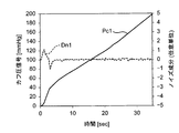
- FIG. 8A and 8B show the noise verification results for the cuff pressure signal Pc by the inventor.
- FIG. 8A is obtained as a fluctuation component of the cuff pressure signal Pc0 (shown by a solid line) and the cuff pressure signal Pc0 at the time of blood pressure measurement in an arrangement in which the wiring 19 overlaps the fluid bag 21 in the width direction in the belt 20.
- the noise component Dn0 (shown by a broken line) is shown.
- FIG. 8B shows a cuff pressure signal Pc1 (shown by a solid line) at the time of blood pressure measurement in the arrangement in which the wiring 19 is separated from the fluid bag 21 in the width direction along the edge 20g in the belt 20 as shown in FIG.
- a noise component Dn1 (indicated by a broken line) obtained as a fluctuation component of the cuff pressure signal Pc1.
- Dn1 a noise component obtained as a fluctuation component of the cuff pressure signal Pc1.
- pulse-like noise which is understood as a shift with friction between the fluid bag 21 and the wiring 19 is sometimes generated, whereas in the cuff pressure signal Pc1 in FIG. Except for noise (several seconds from the start of pressurization), such pulse noise is eliminated.
- the battery housing case 10A is arranged to correspond to the back side surface 90b of the left wrist 90 in the belt 20, but is not limited thereto.
- the battery housing case 10 ⁇ / b> A (and therefore the battery 53) may be disposed in a portion of the belt 20 that is separated from the main body 10, 10 ′ in the circumferential direction surrounding the left wrist 90.
- the battery housing case 10A is disposed in a portion of the belt 20 corresponding to the heel side surface 90c of the left wrist 90 or a portion corresponding to the scale side surface (portion corresponding to the little finger side of the outer peripheral surface of the wrist). Also good.
- the main bodies 10 and 10 ' are scheduled to be arranged corresponding to the palm side surface 90a of the left wrist 90, but the present invention is not limited to this.
- the main bodies 10 and 10 ′ may have specifications designed to be arranged corresponding to the back side surface 90 b of the left wrist 90.
- the alignment mark 29 is provided on a portion of the outer peripheral surface of the belt 20 near the battery housing case 10 ⁇ / b> A (specifically, in FIG. 2A, the alignment mark 29 29 is moved from the lower half of the annular belt 20 to the symmetrical position of the upper half), and the user passes the left hand through the belt 20 from the side opposite to the arrow A.
- the battery housing case 10A (therefore, the battery 53) may be disposed in a portion of the belt 20 that is separated from the main bodies 10 and 10 'in the circumferential direction surrounding the left wrist 90.
- the devices 1 and 1 ′ are scheduled to be attached to the left wrist 90.
- the present invention is not limited to this.
- FIGS. 1 and 7 it is assumed that the user passes the right hand through the belt 20 from the side opposite to the arrow A.
- apparatus 1,1 ' can be conveniently used also for a left-handed user.
- the battery 53 is accommodated in the battery accommodating case 10 ⁇ / b> A and attached to the belt 20.
- the present invention is not limited to this, and the battery 53 may be included in the belt 20 without a storage case.
- a configuration is adopted in which a fluid bag 21 (see FIG. 3) for compressing the wrist is included in the belt 20 and blood pressure is measured by an oscillometric method. did.
- the present invention is not limited to this.
- a semiconductor sensor array having a plurality of pressure sensors (piezoelectric elements) arranged on the inner peripheral surface of the belt 20 is mounted, and a tonometry method (an artery passing through the wrist is partially flattened out of the entire circumference of the blood vessel).
- the blood pressure may be measured by a method in which the blood pressure is non-invasively measured by balancing the internal and external arterial pressures to the extent that That is, in the device of the present invention, the blood pressure measurement function only needs to be able to measure blood pressure using the belt 20 wound around the wrist, and various configurations and methods can be taken to realize the blood pressure measurement function.
Landscapes
- Health & Medical Sciences (AREA)
- Life Sciences & Earth Sciences (AREA)
- Cardiology (AREA)
- Surgery (AREA)
- General Health & Medical Sciences (AREA)
- Engineering & Computer Science (AREA)
- Biomedical Technology (AREA)
- Heart & Thoracic Surgery (AREA)
- Medical Informatics (AREA)
- Molecular Biology (AREA)
- Physics & Mathematics (AREA)
- Animal Behavior & Ethology (AREA)
- Pathology (AREA)
- Public Health (AREA)
- Veterinary Medicine (AREA)
- Biophysics (AREA)
- Vascular Medicine (AREA)
- Physiology (AREA)
- Ophthalmology & Optometry (AREA)
- Dentistry (AREA)
- Oral & Maxillofacial Surgery (AREA)
- Measuring Pulse, Heart Rate, Blood Pressure Or Blood Flow (AREA)
- Measurement Of The Respiration, Hearing Ability, Form, And Blood Characteristics Of Living Organisms (AREA)
Abstract
この発明の機器(1)は、手首を取り巻いて装着される帯状のベルト(20)と、ベルト(20)のうち手首の掌側面または背側面に対応すべき部位に配置された本体(10)とを備える。この本体(10)に血圧測定機能を実行するための要素が搭載されている。ベルト(20)のうち手首を取り巻く周方向に関して本体(10)から離間した部位に、本体(10)に搭載された要素へ電力を供給する電池(53)が配置されている。ベルト(20)内に、流体袋(21)に沿って周方向に延在し、本体(10)に搭載された要素と電池(53)とを電気的に接続する配線(19)が設けられている。配線(19)は、ベルト(20)内で、周方向に対して垂直な幅方向に関して流体袋(21)から外れて縁部に沿って配置されている。
Description
この発明は機器に関し、より詳しくは、血圧測定機能を有し、手首に装着される機器に関する。
従来、この種の機器としては、例えば特許文献1(特開平9-38052号公報)に開示されているように、手首を取り巻いて装着されるカフ帯と、上記カフ帯のうち上記手首の掌側面(手の平側の面)に対応すべき部位に配置された血圧計本体とを備えたものが知られている。血圧計本体には、この本体内の血圧測定のための要素(ポンプ、制御回路など)に電力を供給するための電池が収容されている。
しかしながら、上記機器では、上記本体の外形寸法、例えば手首の外周面に対して垂直な方向の厚さが比較的大きくなっている。この結果、常時装着して使用すると、ユーザの日常活動の邪魔になるという問題がある。
そこで、この発明の課題は、血圧測定機能を有し、手首に装着される機器であって、本体の外形寸法を小型化できるものを提供することにある。
上記従来例の機器を解析したところ、本発明者は、血圧計本体内で電池が占める容積が最も大きいことに着目した。血圧計本体から電池を分離して配置すれば、上記本体の外形寸法、例えば手首の外周面に対して垂直な方向の厚さを小型化できる。ただし、上記本体と上記電池とを電気的に接続する配線にノイズを生ずる可能性があるため、その対策が必要になると考えられる。
上記課題を解決するため、この発明の機器は、
血圧測定機能を有し、手首に装着される機器であって、
手首を周方向に取り巻いて装着される帯状のベルトを備え、このベルトは、上記手首の動脈を圧迫するための上記周方向に延在する流体袋を含み、
上記ベルトのうち上記手首の掌側面または背側面に対応すべき部位に配置された本体を備え、この本体に血圧測定機能を実行するための要素として、少なくとも上記流体袋に空気を供給して圧力制御するための圧力制御部が搭載され、
上記ベルトのうち上記周方向に関して上記本体から離間した部位に、上記本体に搭載された要素へ電力を供給する電池が配置され、
上記ベルト内に、上記流体袋に沿って上記周方向に延在し、上記本体に搭載された要素と上記電池とを電気的に接続する配線が設けられ、
上記配線は、上記ベルト内で、上記周方向に対して垂直な幅方向に関して上記流体袋から外れて縁部に沿って配置されていることを特徴とする。
本明細書で、手首の「掌側面」とは、手首の外周面のうち手の平側に相当する部分を指す。手首の「背側面」とは、手首の外周面のうち手の甲側に相当する部分を指す。
また、「手首」は、左手首と右手首とのいずれであってもよい。
この発明の機器では、ベルトのうち手首を取り巻く周方向に関して本体から離間した部位に、上記本体に搭載された要素へ電力を供給する電池が配置されている。したがって、上記本体内に電池を収容する構成を避け得る。この結果、上記本体の外形寸法を小型化できる。例えば、手首の外周面に対して垂直な方向の厚さを薄厚に設計できる。
また、この機器では、上記ベルト内で上記流体袋に沿って上記周方向に延在する配線によって、上記本体に搭載された要素と上記電池とが電気的に接続されている。この配線を通して上記電池から上記本体に搭載された要素へ電力が供給されて、血圧測定が実行され得る。
また、この機器では、上記本体に搭載された圧力制御部によって、上記流体袋に空気が供給されて、上記流体袋が圧力制御される。これにより、上記手首の動脈が圧迫され、例えば公知のオシロメトリック法によって、血圧測定が実行され得る。
この血圧測定の際に、上記流体袋が圧力制御されて、膨張または収縮する。仮に、上記ベルト内で上記配線が上記幅方向に関して上記流体袋に重なって配置されていれば、上記流体袋の膨張または収縮に起因して、上記流体袋と上記配線とが摩擦をもって相対的にずれて、血圧測定時のカフ圧信号(したがって、脈波信号)に対してノイズを生ずる可能性がある。また、上記配線が、繰り返し屈曲されて、断線する可能性がある。そこで、この機器では、上記ベルト内で、上記配線は、上記周方向に対して垂直な幅方向に関して上記流体袋から外れて縁部に沿って配置されている。したがって、血圧測定時のカフ圧信号(したがって、脈波信号)に対してノイズが生ずるのを防止できる。また、上記配線が断線するのを防止できる。
なお、「機能を実行するための要素」は、「血圧測定機能」以外の他の機能、例えば時計機能、体温測定機能、活動量測定機能などを実行するための要素を含んでいてもよい。
一実施形態の機器では、
上記ベルトは、上記手首を取り巻いた状態で、上記周方向に関して一端部が内周側、他端部が外周側となって互いにオーバラップするように構成され、
上記電池は、上記ベルトのうち上記外周側となる上記他端部に配置されていることを特徴とする。
上記ベルトは、上記手首を取り巻いた状態で、上記周方向に関して一端部が内周側、他端部が外周側となって互いにオーバラップするように構成され、
上記電池は、上記ベルトのうち上記外周側となる上記他端部に配置されていることを特徴とする。
本明細書では、「一端部」、「他端部」とは、それぞれ一端、他端自体に限られず、或る範囲を含んでいてもよい。
この一実施形態の機器では、上記ベルトは、上記手首を取り巻いた状態で、上記周方向に関して一端部が内周側、他端部が外周側となって互いにオーバラップする。したがって、上記ベルトによって上記手首を圧迫して血圧測定を行う場合に、上記手首の圧迫を確実に行うことができ、血圧測定の精度を高めることができる。また、上記電池は、上記ベルトのうち上記外周側となる上記他端部に配置されている。したがって、上記電池の存在が上記ベルトによって上記手首を圧迫する際の障害にならない。
一実施形態の機器では、上記電池が配置された上記部位には電池のみが配置されていることを特徴とする。
本明細書で、「電池のみが配置されている」とは、電池以外の、機能を実行するための要素が配置されていないことを意味する。言い換えれば、電池収容ケースのような専ら収容のための要素は配置され得る。上記電池は、上記ベルトに内包されていてもよいし、または、電池収容ケースに収容されて上記ベルトに取り付けられていてもよい。
この一実施形態の機器では、上記電池以外の、機能を実行するための要素は、上記本体から離間した部位ではなく上記本体に搭載されているので、機器全体としての構成が複雑になるのを避け得る。
以上より明らかなように、この発明の機器によれば、本体の外形寸法を小型化できる。
以下、この発明の実施の形態を、図面を参照しながら詳細に説明する。
(機器の構成)
図1は、この発明の一実施形態の、血圧測定機能を含む複数の機能を有する機器(全体を符号1で示す。)の外観を斜めから見たところ示している。図2(A)は、機器1の本体10を下側にして、図1における矢印A方向から見たところを示している。また、図2(B)、図2(C)、図2(D)は、それぞれ機器1を図2(A)における左側方、右側方、下方から見たところを示している。この機器1は、ユーザの左手首90(後述の図5参照)に装着されることを予定している。
図1は、この発明の一実施形態の、血圧測定機能を含む複数の機能を有する機器(全体を符号1で示す。)の外観を斜めから見たところ示している。図2(A)は、機器1の本体10を下側にして、図1における矢印A方向から見たところを示している。また、図2(B)、図2(C)、図2(D)は、それぞれ機器1を図2(A)における左側方、右側方、下方から見たところを示している。この機器1は、ユーザの左手首90(後述の図5参照)に装着されることを予定している。
これらの図に示すように、この機器1は、大別して、ユーザの左手首90に巻き付けられるべきベルト20と、このベルト20に一体に取り付けられた本体10と、電池収容ケース10Aとを有している。
図1、図2(A)によって良く分かるように、ベルト20は、左手首90を周方向に沿って取り巻くように細長い帯状の形状を有し、左手首90に接すべき内層20aと、この内層20aに対向する外層20bとを備えている。これらの内層20aと外層20bとは、この例では互いの周縁が溶着されて袋状に形成されている。このベルト20内には、左手首を圧迫するための流体袋21(図3参照)が内包されている。
ベルト20は、この機器1が左手首90に装着された状態(以下「装着状態」と呼ぶ。)で、周方向に関して一端部20eが内周側、他端部20fが外周側となって互いにオーバラップするように構成されている。この例では、ベルト20の一端部20eと他端部20fとは、周方向に関して或る範囲(この例では、電池収容ケース10Aの寸法と略一致する範囲)でオーバラップしている。このオーバラップの結果、ベルト20によって左手首90を圧迫して血圧測定を行う場合に、左手首90の略全周を確実に圧迫することができ、血圧測定の精度を高めることができる。
この例では、図2(B)に示すように、ベルト20を環状に維持するために、ベルト20のうち周方向に関して一端部20e側の外層20bの表面(外周面)に、複数の凹部20d,20d,…が周方向に列をなして配置されている。各凹部20dは、外層20bの途中までの深さを有している。一方、図2(A)に示すように、ベルト20のうち他端部20fの内周面に、凹部20dと係合し得る突起20pが形成されている。一端部20e側の凹部20dと他端部20f側の突起20pとが互いに係合することによって、ベルト20を環状に維持できる。
なお、上述の凹部20dと突起20pとの係合に代えて、または、その係合に加えて、例えば一端部20e側の外層20bの表面(外周面)に多数の微細なループを設ける一方、他端部20f側の内層20aの表面(内周面)に多数の微細なフックを設けて、面ファスナを構成してもよい。この面ファスナを設けることによって、ベルト20の一端部20eと他端部20fとを確実に互いに固定できる。
また、ベルト20を常時環状に維持するために、ベルト20内で、例えば流体袋21と外層20bとの間に、周方向に沿って、適度な可撓性を有するカーラを介挿してもよい。
本体10は、ベルト20のうち、周方向に関して、一端部20eと他端部20fとの間の略中央の部位に、一体に取り付けられて配置されている。この例では、本体10が配置された部位は、装着状態で左手首90の掌側面(手の平側の面)90aに対応することが予定されている(後述の図5参照)。
本体10は、ベルト20の外周面に対して垂直な方向に厚さを有する立体的形状を有している。この本体10は、ユーザの日常活動の邪魔にならないように、小型で、薄厚に形成されている。この例では、本体10は、図2(A)によって良く分かるように、ベルト20から外向きに突起した台形状の輪郭を有している。具体的には、本体10の、周方向に関して両側に相当する側面10e,10fは、この本体10の中心線Cに関して左右対称に形成されている。そして、これらの側面10e,10fは、ベルト20から遠ざかるに連れて、ベルト20の外周面に対する法線Nよりも中心線Cに近づく向きに傾斜している。法線Nに対する側面10fの傾斜角δは、例えば30°~70°の範囲内であるのが望ましく、40°~60°の範囲内であるのがより望ましく、この例ではδ≒50°に設定されている。また、図2(D)によって良く分かるように、本体10の、幅方向(周方向に対して垂直な方向)に関して両側に相当する側面10c,10dは、互いに平行に形成されている。また、図2(A)によって良く分かるように、本体10の外面のうち左手首90から最も遠い側の面(以下「頂面」と呼ぶ。)10aは、周方向に沿って、ベルト20の曲率半径よりも大きい曲率半径で湾曲している。本体10の幅方向寸法は、ベルト20の幅方向寸法と略一致している。
本体10の頂面10aには、ユーザからの指示を入力するための操作部52が設けられている。本体10の側面10fには、表示画面をなす表示器50が設けられている。この側面10fは、装着状態で本体10の外面のうち左手首90の橈側面(左手首90の外周面のうち親指側に相当する部分)90cに面する側の側面部分に相当する(後述の図5参照)。本体10の側面10eには、マイクロUSB(Universal Serial Bus)コネクタ58が設けられている。
ベルト20の外周面には、本体10の側面10fに沿って、幅方向に延びる位置合わせマーク29が設けられている。この位置合わせマーク29は、機器1を左手首90に装着する際に、左手首90の周りの位置合わせのために用いられる。
電池収容ケース10Aは、ベルト20のうち周方向に関して本体10から離間した部位に、この例では、ベルト20のうち外周側となる他端部20fに一体に取り付けられて配置されている。この電池収容ケース10Aは、電池53を収容し(図3参照)、この例では偏平な略直方体状の立体的形状を有している。このように、電池収容ケース10Aがベルト20のうち外周側となる他端部20fに配置されているので、電池収容ケース10A(したがって、電池53)の存在がベルト20によって左手首90を圧迫する際の障害にはならない。
図3は、機器1のブロック構成を示している。この機器1は、血圧測定機能のほか、時計機能、体温測定機能、活動量測定機能などの複数の機能を備えている。
この機器1の本体10には、それらの機能を実行するための要素として、上述の表示器50、操作部52に加えて、制御部としてのCPU(Central Processing Unit)100、記憶部としてのメモリ51、通信部59、ポンプ32、弁33、圧力センサ31、および加速度センサ34が搭載されている。さらに、本体10には、圧力センサ31からの出力を周波数に変換する発振回路310、ポンプ32を駆動するポンプ駆動回路320、弁33を駆動する弁駆動回路330、加速度センサ34からの出力をAD(Analog to Digital)変換するAD変換器340が搭載されている。
表示器50は、この例では有機EL(Electro Luminescence)ディスプレイからなり、CPU100からの制御信号に従って、血圧測定結果などの血圧測定に関する情報、その他の情報を表示する。なお、表示器50は、有機ELディスプレイに限られるものではなく、例えばLCD(Liquid Cristal Display)など、他のタイプの表示器からなっていてもよい。
操作部52は、この例ではプッシュ式スイッチからなり、ユーザによる血圧測定開始又は停止の指示に応じた操作信号をCPU100に入力する。なお、操作部52は、プッシュ式スイッチに限られるものではなく、例えば感圧式(抵抗式)または近接式(静電容量式)のタッチパネル式スイッチなどであってもよい。また、図示しないマイクロフォンを備えて、ユーザの音声によって血圧測定開始の指示を入力するようにしてもよい。
メモリ51は、機器1を制御するためのプログラムのデータ、機器1を制御するために用いられるデータ、機器1の各種機能を設定するための設定データ、血圧値の測定結果のデータなどを非一時的に記憶する。また、メモリ51は、プログラムが実行されるときのワークメモリなどとして用いられる。
CPU100は、メモリ51に記憶された機器1を制御するためのプログラムに従って、制御部として各種機能を実行する。例えば、血圧測定機能を実行する場合は、CPU100は、操作部52からの操作信号に応じて、ポンプ32や弁33を駆動する制御を行う。また、CPU100は、圧力センサ31からの信号に基づいて、血圧値を算出する制御を行う。さらに、CPU100は、加速度センサ34の出力に基づいて、ユーザの左手首90の姿勢、活動量などを検出する制御を行う。
通信部59は、CPU100によって制御されて所定の情報を、ネットワーク900を介して外部の装置に送信したり、外部の装置からの情報を、ネットワーク900を介して受信してCPU100に受け渡したりする。このネットワーク900を介した通信は、無線、有線のいずれでも良い。この実施形態において、ネットワーク900は、インターネットであるが、これに限定されず、病院内LAN(Local Area Network)のような他の種類のネットワークであってもよいし、USBケーブルなどを用いた1対1の通信であってもよい。この通信部59は、既述のマイクロUSBコネクタ58を含んでいる。
ポンプ32、弁33および圧力センサ31は、配管系としての共通のエア配管39を介して、ベルト20に内包されている流体袋21に接続されている。ポンプ32は、ベルト20に内包された流体袋21内の圧力(カフ圧)を加圧するために、エア配管39を通して流体袋21に空気を供給する。弁33は、通電によって開閉が制御される電磁弁であり、流体袋21の空気をエア配管39を通して排出し、または封入してカフ圧を制御するために用いられる。ポンプ駆動回路320は、ポンプ32をCPU100から与えられる制御信号に基づいて駆動する。弁駆動回路330は、弁33をCPU100から与えられる制御信号に基づいて開閉する。
圧力センサ31は、この例ではピエゾ抵抗式圧力センサであり、エア配管39を通してベルト20(流体袋21)の圧力、この例では大気圧を基準(ゼロ)とした圧力を検出して時系列のカフ圧信号Pcとして出力する。発振回路310は、圧力センサ31からのピエゾ抵抗効果による電気抵抗の変化に基づく電気信号値に基づき発振して、圧力センサ31の電気信号値に応じた周波数を有する周波数信号をCPU100に出力する。
この例では、圧力センサ31の出力は、オシロメトリック法によって、血圧値(収縮期血圧(Systolic Blood Pressure)と拡張期血圧(Diastolic Blood Pressure)とを含む。)を算出するのに用いられる。また、圧力センサ31の出力は、脈拍を算出するのに用いられる。
分かるように、圧力センサ31、ポンプ32、弁33、発振回路310、ポンプ駆動回路320、弁駆動回路330、および、CPU100は、流体袋21に空気を供給して圧力制御するための圧力制御部を構成している。
加速度センサ34は、本体10内に一体に内蔵された3軸加速度センサからなる。この加速度センサ34は、本体10の、したがって本体10と一体に取り付けられたベルト20の、互いに直交する3方向の加速度を表す加速度信号を、AD変換器340を介して、CPU100に出力する。この例では、加速度センサ34の出力は、ユーザの左手首90の姿勢、活動量などを検出するのに用いられる。
電池収容ケース10Aには、電池53のみが収容されている。ベルト20内には、流体袋21に沿って(ベルト20の)周方向に延在し、本体10に搭載された要素と電池53とを電気的に接続する配線19が設けられている。電池53は、ベルト20内を通る配線19を介して、本体10に搭載された要素、この例では、CPU100、圧力センサ31、ポンプ32、弁33、加速度センサ34、表示器50、メモリ51、通信部59、発振回路310、ポンプ駆動回路320、弁駆動回路330、およびAD変換器340の各要素へ電力を供給する。
この機器1では、時計機能は、CPU100が内蔵するクロックによって実現される。体温測定機能は、図示しない温度計の出力を用いて実現される。活動量測定機能は、加速度センサ34の出力を用いて実現される。
(血圧測定機能の動作)
この機器1を左手首90に装着する際には、ベルト20の一端部20eと他端部20fとの係合を解除した状態で、図1中に矢印Aで示す向きに、ユーザがベルト20に左手を通す。そして、図5に示すように、ユーザは、左手首90の周りのベルト20の角度位置を調節して、左手首90を通っている動脈90u上にベルト20の位置合わせマーク29を位置させる。この状態で、ユーザが、自分の左手首90の周囲長に応じてベルト20の一端部20e側の凹部20d,20d,…のうち適切なもの(左手首90の周囲長にベルト20の環の長さが丁度合うような凹部20d)を選択し、その凹部20dと他端部20f側の突起20pとを互いに係合させる。このようにして、機器1を左手首90に装着する。この装着状態では、左手首90の掌側面90aに対応して本体10が配置され、また、左手首90の背側面90bに対応して電池収容ケース10Aが配置される。表示器50は、左手首90の橈側面90cの側へ向いている。
この機器1を左手首90に装着する際には、ベルト20の一端部20eと他端部20fとの係合を解除した状態で、図1中に矢印Aで示す向きに、ユーザがベルト20に左手を通す。そして、図5に示すように、ユーザは、左手首90の周りのベルト20の角度位置を調節して、左手首90を通っている動脈90u上にベルト20の位置合わせマーク29を位置させる。この状態で、ユーザが、自分の左手首90の周囲長に応じてベルト20の一端部20e側の凹部20d,20d,…のうち適切なもの(左手首90の周囲長にベルト20の環の長さが丁度合うような凹部20d)を選択し、その凹部20dと他端部20f側の突起20pとを互いに係合させる。このようにして、機器1を左手首90に装着する。この装着状態では、左手首90の掌側面90aに対応して本体10が配置され、また、左手首90の背側面90bに対応して電池収容ケース10Aが配置される。表示器50は、左手首90の橈側面90cの側へ向いている。
この装着状態で、ユーザは、血圧測定を行うために、例えば製品の取扱説明書に従って、図6(A)、図6(B)に示したような推奨血圧測定姿勢、すなわち、前腕を体幹に対して前方で斜め(手が上、肘が下)に交差して挙げて、左手首90を心臓91の高さレベルに維持し、かつ、左手首90の橈側面90cを上へ向けた姿勢をとる。すると、表示器50は、上方へ面した状態になる。また、図2(A)中に示したように、本体10の外面のうち表示器50が配置された側面10fは、ベルト20から遠ざかるに連れて、ベルト20の外周面に対する法線Nよりも中心線Cに近づく向きに傾斜している。したがって、ユーザが推奨血圧測定姿勢(図6(A)、図6(B))をとれば、表示器(表示画面)50は、左手首90の周りに関して、ユーザの視線に対して垂直に近づく。
この状態で、ユーザが本体10に設けられた操作部52としてのプッシュ式スイッチを右手で押すと、血圧測定が開始される。
図4は、機器1が血圧測定を行う際の動作フローを示している。血圧測定開始に際して、CPU100は、処理用メモリ領域を初期化し、弁駆動回路330に制御信号を出力する。弁駆動回路330は、制御信号に基づいて、弁33を開放してベルト20の流体袋21内の空気を排気する。続いて、圧力センサ31の0mmHgの調整を行う制御を行う。
血圧測定期間(準備期間を含む。)中、CPU100は、表示器50に、血圧測定の進捗状況を示す表示として、この例では、進捗に応じて横棒が0%から100%まで伸びてゆくプログレスバーを表示する。
血圧測定を開始すると、まず、CPU100は、弁駆動回路330を介して弁33を閉鎖し、その後、ポンプ駆動回路320を介してポンプ32を駆動して、流体袋21に空気を送る制御を行う。これにより、流体袋21を膨張させるとともにカフ圧を徐々に加圧していく(図4のステップST101)。これにより、左手首90の動脈90uが圧迫される。
カフ圧が加圧されて所定の圧力に達すると(ステップST102でYES)、CPU100は、ポンプ駆動回路320を介してポンプ32を停止し、その後、弁駆動回路330を介して弁33を徐々に開放する制御を行う。これにより、流体袋21を収縮させるとともにカフ圧を徐々に減圧していく(ステップST103)。
ここで、所定の圧力とは、被験者の収縮期血圧よりも十分高い圧力(例えば、収縮期血圧+30mmHg)であり、予めメモリ51に記憶されているか、カフ圧の加圧中にCPU100が収縮期血圧を所定の算出式により推定して決定する(例えば特開2001-70263号公報参照)。
また、減圧速度については、カフ圧の加圧中に目標となる目標減圧速度を設定し、その目標減圧速度になるようにCPU100が弁33の開口度を制御する(同公報参照)。
上記減圧過程において、圧力センサ31がベルト20の圧力を検出してカフ圧信号Pcを出力する。CPU100は、このカフ圧信号Pcに基づいて、オシロメトリック法により公知のアルゴリズムを適用して血圧値(収縮期血圧と拡張期血圧)を算出する(ステップST104)。また、CPU100は、カフ圧信号Pcに基づいて、脈拍も算出する。なお、血圧値、脈拍の算出は、減圧過程に限らず、加圧過程において行われてもよい。
血圧値を算出して決定すると(ステップST105でYES)、CPU100は、血圧測定に関する情報として、その血圧測定によって得られた血圧値を表示器50に表示する(ステップST106)。また、CPU100は、血圧値をメモリ51へ保存する制御を行う(ステップST107)。
血圧値の表示としては、表示器50に、例えば「最高血圧:120mmHg 最低血圧:80mmHg」のような表示を行う。それに併せて、脈拍を例えば「脈拍:70拍/分」のように表示してもよい。
測定が終了すると、CPU100は、弁駆動回路330を介して弁33を開放し、ベルト20の流体袋21内の空気を排気する制御を行う(ステップST108)。これにより、血圧測定を終了する。
上述のように、CPU100は、表示器50に、血圧測定に関する情報として、血圧測定の進捗状況を示す表示、および、血圧測定によって得られた血圧値を示す表示を行う。
ここで、血圧測定の期間中、ユーザが推奨血圧測定姿勢(図6(A)、図6(B))をとっていれば、上述のように、本体10の外面のうち表示器50が配置された側面10fは、上方へ面している。したがって、ユーザは上方から、上方へ面する表示器(表示画面)50を見ることになる。また、この例では、表示器50が配置された側面10fは、ベルト20の外周面に対する法線Nよりも左手首90の橈側面90cから遠ざかる向きに傾斜している。この結果、表示器50は、左手首90の周りに関して、ユーザの視線に対して垂直に近づいている。したがって、従来例に比して、ユーザにとって表示内容が見易くなる。この結果、ユーザが、意識的に又は無意識に、左手首90を捻って左手首90の背側面(手の甲側の面)90bを上へ向けてしまうのを防止できる。したがって、血圧測定精度を高めることができる。
また、この機器1では、ベルト20のうち左手首90を取り巻く周方向に関して本体10から離間した部位に、本体10に搭載された要素へ電力を供給する電池53が配置されている。したがって、本体10内に電池53を収容する構成を避け得る。この結果、本体10の外形寸法、例えば左手首90の外周面に対して垂直な方向の厚さを小型化できる。また、電池53以外の、機能を実行するための要素は、本体10から離間した部位ではなく本体10に搭載されているので、機器1全体としての構成が複雑になるのを避け得る。
図7は、図2(C)においてベルト20の外層20bの一部を取り除いて、ベルト20内の流体袋21と配線19との配置を示している。図7から分かるように、この例では、ベルト20内で、配線19は、幅方向に関して流体袋21から外れて縁部20gに沿って配置されている。この理由は、次の通りである。すなわち、仮に、ベルト20内で配線19が幅方向に関して流体袋21に重なって配置されていれば、血圧測定の際に、流体袋21の膨張または収縮に起因して、流体袋21と配線19とが摩擦をもって相対的にずれて、血圧測定時のカフ圧信号Pc(したがって、カフ圧信号Pcの変動成分として得られる脈波信号)に対してノイズが生ずる可能性がある。また、配線19が、繰り返し屈曲されて、断線する可能性がある。そこで、この機器1では、上述のように、ベルト20内で、配線19は、幅方向に関して流体袋21から外れて、縁部20gに沿って配置されている。したがって、血圧測定時のカフ圧信号Pc(したがって、カフ圧信号Pcの変動成分として得られる脈波信号)に対してノイズが生ずるのを防止できる。また、配線19が断線するのを防止できる。
図8A、図8Bは、本発明者による、カフ圧信号Pcに対するノイズの検証結果を示している。図8Aは、ベルト20内で配線19が幅方向に関して流体袋21に重なった配置での、血圧測定時のカフ圧信号Pc0(実線で示す)、および、カフ圧信号Pc0の変動成分として得られたノイズ成分Dn0(破線で示す)を示している。図8Bは、図7に示したようにベルト20内で配線19が幅方向に関して流体袋21から外れて縁部20gに沿った配置での、血圧測定時のカフ圧信号Pc1(実線で示す)、および、カフ圧信号Pc1の変動成分として得られたノイズ成分Dn1(破線で示す)を示している。図8Aのカフ圧信号Pc0では、流体袋21と配線19との摩擦をもったずれと解されるパルス状のノイズが時々生じているのに対して、図8Bのカフ圧信号Pc1では、初期(加圧開始から数秒間)のノイズを除いて、そのようなパルス状のノイズは解消されている。
上述の実施形態では、電池収容ケース10Aがベルト20のうち左手首90の背側面90bに対応して配置されるものとしたが、これに限られるものではない。電池収容ケース10A(したがって、電池53)は、ベルト20のうち左手首90を取り巻く周方向に関して本体10,10′から離間した部位に配置されればよい。例えば、電池収容ケース10Aは、ベルト20のうち左手首90の橈側面90cに対応する部位、または、尺側面(手首の外周面のうち小指側に相当する部分)に対応する部位に配置されてもよい。
また、上述の実施形態では、本体10,10′が左手首90の掌側面90aに対応して配置されることを予定したが、これに限られるものではない。本体10,10′は、左手首90の背側面90bに対応して配置されることを予定した仕様としてもよい。その仕様では、例えば、図1、図7において、それぞれ、位置合わせマーク29をベルト20の外周面のうち電池収容ケース10Aに近い部位に設け(詳しくは、図2(A)において、位置合わせマーク29を環状のベルト20の下半分から上半分の対称な位置に移動させ)、ユーザがベルト20に矢印Aと反対の側から左手を通すものとする。その場合も、電池収容ケース10A(したがって、電池53)は、ベルト20のうち左手首90を取り巻く周方向に関して本体10,10′から離間した部位に配置されればよい。
また、上述の実施形態では、機器1,1′は、左手首90に装着されることが予定されているものとした。しかしながら、これに限られるものではない。例えば、図1、図7において、それぞれ、ユーザがベルト20に矢印Aと反対の側から右手を通すものとする。これにより、機器1,1′は、左利きのユーザにとっても便利に使用され得る。
また、上述の実施形態では、電池53は、電池収容ケース10Aに収容されてベルト20に取り付けられているものとした。しかしながら、これに限られるものではなく、電池53は、収容ケース無しで、ベルト20に内包されていてもよい。
また、上述の実施形態では、血圧測定機能を実現するために、ベルト20内に手首を圧迫するための流体袋21(図3参照)が内包され、オシロメトリック法によって血圧を測定する構成を採用した。しかしながら、これに限られるものではない。例えば、ベルト20の内周面に、複数並ぶ圧力センサ(圧電素子)を備えた半導体センサアレイを搭載し、トノメトリ法(手首を通っている動脈を、血管の全周のうちの一部が平坦になる程度に押し、動脈内圧と外圧をバランスさせて非侵襲的に血圧を測定する方法)によって血圧を測定する構成を採用してもよい。つまり、本発明の機器では、血圧測定機能については手首に巻き付けられたベルト20を用いて血圧を測定できればよく、血圧測定機能を実現するために様々な構成および方法をとり得る。
以上の実施形態は例示であり、この発明の範囲から離れることなく様々な変形が可能である。上述した複数の実施の形態は、それぞれ単独で成立し得るものであるが、実施の形態同士の組みあわせも可能である。また、異なる実施の形態の中の種々の特徴も、それぞれ単独で成立し得るものであるが、異なる実施の形態の中の特徴同士の組みあわせも可能である。
1,1′ 機器
10,10′ 本体
10A 電池収容ケース
11 主部
12 基部
19 配線
20 ベルト
50 表示器
52 操作部
53 電池
10,10′ 本体
10A 電池収容ケース
11 主部
12 基部
19 配線
20 ベルト
50 表示器
52 操作部
53 電池
Claims (3)
- 血圧測定機能を有し、手首に装着される機器であって、
手首を周方向に取り巻いて装着される帯状のベルトを備え、このベルトは、上記手首の動脈を圧迫するための上記周方向に延在する流体袋を含み、
上記ベルトのうち上記手首の掌側面または背側面に対応すべき部位に配置された本体を備え、この本体に血圧測定機能を実行するための要素として、少なくとも上記流体袋に空気を供給して圧力制御するための圧力制御部が搭載され、
上記ベルトのうち上記周方向に関して上記本体から離間した部位に、上記本体に搭載された要素へ電力を供給する電池が配置され、
上記ベルト内に、上記流体袋に沿って上記周方向に延在し、上記本体に搭載された要素と上記電池とを電気的に接続する配線が設けられ、
上記配線は、上記ベルト内で、上記周方向に対して垂直な幅方向に関して上記流体袋から外れて縁部に沿って配置されていることを特徴とする機器。 - 請求項1に記載の機器において、
上記ベルトは、上記手首を取り巻いた状態で、上記周方向に関して一端部が内周側、他端部が外周側となって互いにオーバラップするように構成され、
上記電池は、上記ベルトのうち上記外周側となる上記他端部に配置されていることを特徴とする機器。 - 請求項1または2に記載の機器において、
上記電池が配置された上記部位には電池のみが配置されていることを特徴とする機器。
Priority Applications (3)
| Application Number | Priority Date | Filing Date | Title |
|---|---|---|---|
| EP16883869.6A EP3384840B1 (en) | 2016-01-04 | 2016-12-27 | Instrument having a blood pressure measuring function |
| CN201680077598.1A CN108471965B (zh) | 2016-01-04 | 2016-12-27 | 具有血压测量功能的设备 |
| US16/026,173 US11382523B2 (en) | 2016-01-04 | 2018-07-03 | Instrument having a blood pressure measuring function |
Applications Claiming Priority (2)
| Application Number | Priority Date | Filing Date | Title |
|---|---|---|---|
| JP2016-000262 | 2016-01-04 | ||
| JP2016000262A JP6750225B2 (ja) | 2016-01-04 | 2016-01-04 | 機器 |
Related Child Applications (1)
| Application Number | Title | Priority Date | Filing Date |
|---|---|---|---|
| US16/026,173 Continuation US11382523B2 (en) | 2016-01-04 | 2018-07-03 | Instrument having a blood pressure measuring function |
Publications (1)
| Publication Number | Publication Date |
|---|---|
| WO2017119370A1 true WO2017119370A1 (ja) | 2017-07-13 |
Family
ID=59273540
Family Applications (1)
| Application Number | Title | Priority Date | Filing Date |
|---|---|---|---|
| PCT/JP2016/088957 Ceased WO2017119370A1 (ja) | 2016-01-04 | 2016-12-27 | 機器 |
Country Status (5)
| Country | Link |
|---|---|
| US (1) | US11382523B2 (ja) |
| EP (1) | EP3384840B1 (ja) |
| JP (1) | JP6750225B2 (ja) |
| CN (1) | CN108471965B (ja) |
| WO (1) | WO2017119370A1 (ja) |
Cited By (2)
| Publication number | Priority date | Publication date | Assignee | Title |
|---|---|---|---|---|
| WO2019131242A1 (ja) * | 2017-12-28 | 2019-07-04 | オムロンヘルスケア株式会社 | 血圧測定装置及びコネクタ |
| WO2019139038A1 (ja) * | 2018-01-15 | 2019-07-18 | オムロン株式会社 | ベルト、血圧測定装置、及びベルトの製造方法 |
Families Citing this family (4)
| Publication number | Priority date | Publication date | Assignee | Title |
|---|---|---|---|---|
| US10874307B2 (en) | 2017-01-24 | 2020-12-29 | Verily Life Sciences Llc | Digital artery blood pressure monitor |
| JP7202886B2 (ja) * | 2018-12-27 | 2023-01-12 | オムロンヘルスケア株式会社 | 血圧測定装置 |
| USD918071S1 (en) * | 2019-04-18 | 2021-05-04 | KHN Solutions, Inc. | Biomonitoring wristband |
| US12419527B2 (en) | 2021-09-29 | 2025-09-23 | Verily Life Sciences Llc | Comprehensive wearable vital signs monitor |
Citations (3)
| Publication number | Priority date | Publication date | Assignee | Title |
|---|---|---|---|---|
| JP2004254717A (ja) * | 2003-02-24 | 2004-09-16 | Matsushita Electric Works Ltd | 血圧計のカフ帯及びそれを用いた血圧計 |
| JP2008161687A (ja) * | 2007-01-03 | 2008-07-17 | General Electric Co <Ge> | 組み合わせ型子宮活動および胎児心拍数モニタ |
| JP2013143997A (ja) * | 2012-01-13 | 2013-07-25 | Microstone Corp | 身体装着装置 |
Family Cites Families (11)
| Publication number | Priority date | Publication date | Assignee | Title |
|---|---|---|---|---|
| JPH0938052A (ja) | 1995-07-31 | 1997-02-10 | Matsushita Electric Works Ltd | 手首血圧計 |
| JP4430268B2 (ja) * | 2001-07-27 | 2010-03-10 | テルモ株式会社 | カフ装置およびそれを備える血圧計 |
| JP4590998B2 (ja) * | 2004-09-15 | 2010-12-01 | オムロンヘルスケア株式会社 | 血圧計 |
| JP4240034B2 (ja) * | 2005-11-30 | 2009-03-18 | オムロンヘルスケア株式会社 | 血圧測定装置 |
| US20080071180A1 (en) * | 2006-05-24 | 2008-03-20 | Tarilian Laser Technologies, Limited | Vital Sign Detection Method and Measurement Device |
| JP2010069196A (ja) * | 2008-09-22 | 2010-04-02 | Omron Healthcare Co Ltd | 血圧計用カフおよび血圧計 |
| JP4414485B1 (ja) * | 2009-10-16 | 2010-02-10 | テルモ株式会社 | カフ装置を備える血圧計 |
| KR101350935B1 (ko) * | 2012-02-16 | 2014-01-15 | 제주대학교 산학협력단 | 혈압 측정용 신축성 고무링 커프 |
| JP5910212B2 (ja) * | 2012-03-19 | 2016-04-27 | オムロンヘルスケア株式会社 | 血圧測定装置 |
| KR20150092465A (ko) * | 2014-02-05 | 2015-08-13 | 이동화 | 손목시계형 혈압계 |
| CN204863156U (zh) * | 2015-07-08 | 2015-12-16 | 深圳欧德蒙科技有限公司 | 腕式血压测量装置 |
-
2016
- 2016-01-04 JP JP2016000262A patent/JP6750225B2/ja active Active
- 2016-12-27 CN CN201680077598.1A patent/CN108471965B/zh active Active
- 2016-12-27 WO PCT/JP2016/088957 patent/WO2017119370A1/ja not_active Ceased
- 2016-12-27 EP EP16883869.6A patent/EP3384840B1/en active Active
-
2018
- 2018-07-03 US US16/026,173 patent/US11382523B2/en active Active
Patent Citations (3)
| Publication number | Priority date | Publication date | Assignee | Title |
|---|---|---|---|---|
| JP2004254717A (ja) * | 2003-02-24 | 2004-09-16 | Matsushita Electric Works Ltd | 血圧計のカフ帯及びそれを用いた血圧計 |
| JP2008161687A (ja) * | 2007-01-03 | 2008-07-17 | General Electric Co <Ge> | 組み合わせ型子宮活動および胎児心拍数モニタ |
| JP2013143997A (ja) * | 2012-01-13 | 2013-07-25 | Microstone Corp | 身体装着装置 |
Cited By (6)
| Publication number | Priority date | Publication date | Assignee | Title |
|---|---|---|---|---|
| WO2019131242A1 (ja) * | 2017-12-28 | 2019-07-04 | オムロンヘルスケア株式会社 | 血圧測定装置及びコネクタ |
| US12446827B2 (en) | 2017-12-28 | 2025-10-21 | Omron Healthcare Co., Ltd. | Blood pressure measuring device |
| WO2019139038A1 (ja) * | 2018-01-15 | 2019-07-18 | オムロン株式会社 | ベルト、血圧測定装置、及びベルトの製造方法 |
| JP2019122510A (ja) * | 2018-01-15 | 2019-07-25 | オムロン株式会社 | ベルト、血圧測定装置、及びベルトの製造方法 |
| CN111601547A (zh) * | 2018-01-15 | 2020-08-28 | 欧姆龙株式会社 | 带、血压测量装置、以及带的制造方法 |
| CN111601547B (zh) * | 2018-01-15 | 2023-09-05 | 欧姆龙株式会社 | 带、血压测量装置、以及带的制造方法 |
Also Published As
| Publication number | Publication date |
|---|---|
| JP2017121277A (ja) | 2017-07-13 |
| US11382523B2 (en) | 2022-07-12 |
| US20180310835A1 (en) | 2018-11-01 |
| EP3384840A1 (en) | 2018-10-10 |
| EP3384840A4 (en) | 2019-04-24 |
| EP3384840B1 (en) | 2020-04-01 |
| CN108471965A (zh) | 2018-08-31 |
| JP6750225B2 (ja) | 2020-09-02 |
| CN108471965B (zh) | 2021-03-02 |
Similar Documents
| Publication | Publication Date | Title |
|---|---|---|
| WO2017119370A1 (ja) | 機器 | |
| US10765366B2 (en) | Appliance | |
| US11918327B2 (en) | Sphygmomanometer, blood pressure measurement method, and device | |
| JP7124552B2 (ja) | 測定装置 | |
| JP7049895B2 (ja) | 血圧測定装置 | |
| WO2017203957A1 (ja) | 血圧測定用カフおよび血圧計 | |
| JP6761337B2 (ja) | 脈波測定装置および脈波測定方法、並びに血圧測定装置 | |
| JP2017209433A5 (ja) | ||
| WO2018123374A1 (ja) | 血圧計および血圧測定方法並びに機器 | |
| JP2017121276A (ja) | 機器 | |
| WO2018123386A1 (ja) | 血圧関連情報表示装置、血圧関連情報表示方法およびプログラム | |
| US11317818B2 (en) | Blood pressure measurement device and blood pressure measurement method | |
| KR101680197B1 (ko) | 손목 혈압계 | |
| US12303241B2 (en) | Sphygmomanometer, blood pressure calculation method, and computer-readable recording medium | |
| JP7238260B2 (ja) | 生体情報測定装置 | |
| WO2022244718A1 (ja) | 血圧測定装置 | |
| JP6837881B2 (ja) | 生体情報測定装置、方法及びプログラム | |
| JP2021030037A (ja) | 血圧計、血圧算出方法、およびプログラム | |
| CN119156170A (zh) | 手腕用血压计 |
Legal Events
| Date | Code | Title | Description |
|---|---|---|---|
| 121 | Ep: the epo has been informed by wipo that ep was designated in this application |
Ref document number: 16883869 Country of ref document: EP Kind code of ref document: A1 |
|
| WWE | Wipo information: entry into national phase |
Ref document number: 2016883869 Country of ref document: EP |
|
| NENP | Non-entry into the national phase |
Ref country code: DE |
|
| ENP | Entry into the national phase |
Ref document number: 2016883869 Country of ref document: EP Effective date: 20180702 |