WO2017119490A1 - 基地局、ユーザ装置、及びコンテクスト情報保持方法 - Google Patents
基地局、ユーザ装置、及びコンテクスト情報保持方法 Download PDFInfo
- Publication number
- WO2017119490A1 WO2017119490A1 PCT/JP2017/000294 JP2017000294W WO2017119490A1 WO 2017119490 A1 WO2017119490 A1 WO 2017119490A1 JP 2017000294 W JP2017000294 W JP 2017000294W WO 2017119490 A1 WO2017119490 A1 WO 2017119490A1
- Authority
- WO
- WIPO (PCT)
- Prior art keywords
- information
- context
- base station
- capability
- enb
- Prior art date
- Legal status (The legal status is an assumption and is not a legal conclusion. Google has not performed a legal analysis and makes no representation as to the accuracy of the status listed.)
- Ceased
Links
Images









Classifications
-
- H—ELECTRICITY
- H04—ELECTRIC COMMUNICATION TECHNIQUE
- H04W—WIRELESS COMMUNICATION NETWORKS
- H04W76/00—Connection management
- H04W76/20—Manipulation of established connections
-
- H—ELECTRICITY
- H04—ELECTRIC COMMUNICATION TECHNIQUE
- H04W—WIRELESS COMMUNICATION NETWORKS
- H04W8/00—Network data management
- H04W8/22—Processing or transfer of terminal data, e.g. status or physical capabilities
-
- H—ELECTRICITY
- H04—ELECTRIC COMMUNICATION TECHNIQUE
- H04W—WIRELESS COMMUNICATION NETWORKS
- H04W4/00—Services specially adapted for wireless communication networks; Facilities therefor
- H04W4/70—Services for machine-to-machine communication [M2M] or machine type communication [MTC]
-
- H—ELECTRICITY
- H04—ELECTRIC COMMUNICATION TECHNIQUE
- H04W—WIRELESS COMMUNICATION NETWORKS
- H04W76/00—Connection management
- H04W76/10—Connection setup
- H04W76/19—Connection re-establishment
-
- H—ELECTRICITY
- H04—ELECTRIC COMMUNICATION TECHNIQUE
- H04W—WIRELESS COMMUNICATION NETWORKS
- H04W76/00—Connection management
- H04W76/20—Manipulation of established connections
- H04W76/27—Transitions between radio resource control [RRC] states
-
- H—ELECTRICITY
- H04—ELECTRIC COMMUNICATION TECHNIQUE
- H04W—WIRELESS COMMUNICATION NETWORKS
- H04W76/00—Connection management
- H04W76/30—Connection release
-
- H—ELECTRICITY
- H04—ELECTRIC COMMUNICATION TECHNIQUE
- H04W—WIRELESS COMMUNICATION NETWORKS
- H04W88/00—Devices specially adapted for wireless communication networks, e.g. terminals, base stations or access point devices
- H04W88/08—Access point devices
-
- H—ELECTRICITY
- H04—ELECTRIC COMMUNICATION TECHNIQUE
- H04W—WIRELESS COMMUNICATION NETWORKS
- H04W92/00—Interfaces specially adapted for wireless communication networks
- H04W92/04—Interfaces between hierarchically different network devices
- H04W92/12—Interfaces between hierarchically different network devices between access points and access point controllers
Definitions
- the present invention relates to a technology in which each of the user equipment UE and the base station eNB in the mobile communication system holds a UE context.
- a connection state between a user apparatus UE (hereinafter referred to as UE) and a base station eNB (hereinafter referred to as eNB) is an RRC (Radio Resource Control) idle state (RRC_Idle) and an RRC connection state. (RRC_Connected).
- RRC Radio Resource Control
- the UE context is information including bearer related information, security related information, and the like.
- Non-Patent Document 1 when the UE transitions from the RRC connected state to the RRC idle state, signaling as shown in FIG. 1 occurs (Non-Patent Document 1, etc.).
- the case of FIG. 1 is a case where the eNB 2 detects that the communication of the UE 1 does not occur for a predetermined time, disconnects the connection with the UE 1, and transitions to the RRC idle state.
- eNB 2 transmits a UE context release request (UE ⁇ Context Release Request) to MME 3 (step 1).
- the MME 3 transmits a bearer release request (Release Access Bearers request) to the S-GW 4 (step 2), and the S-GW 4 returns a bearer release response (Release Access Bearers response) to the MME 3 (step 3).
- the MME 3 transmits a UE context release instruction (UE Context Release Command) to the eNB 2 (step 4).
- eNB2 transmits RRC connection release (RRC Connection Release) to UE1 (step 5), causes UE1 to release the UE context, and transitions to the RRC idle state.
- eNB2 releases UE context and transmits UE context release completion (UE
- 3GPP TS 36.413 V12.4.0 (2014-12) 3GPP TSG RAN Meeting # 66 RP-142030 Maui, USA, 8th-11th December 2014 3GPP TR 23.720 V1.1.0 (2015-10) 3GPP TSG-RAN WG3 Meeting # 90 R3-152688 Anaheim, CA, U.S., 16th-20th November 2015 3GPP TS 36.331 V12.6.0 (2015-06)
- Non-Patent Document 2 An example of a procedure conceivable in the method will be described with reference to FIG.
- UE1 In the state shown in FIG. 2A, UE1 is in the RRC connection state, and the S1-C connection and the S1-U connection (S1-C / U in the figure) related to the UE1 are established on the core NW side. It is a state that has been.
- the S1-C connection is an S1 connection that sends a C-plane signal
- the S1-U connection is an S1 connection that passes a U-plane.
- UE1 is transitioned to the RRC idle state by RRC connection release (RRC Connection Release).
- RRC connection release RRC Connection Release
- the UE context for UE1 in eNB2 is maintained
- the UE context for eNB2 in UE1 is also maintained
- the S1-C / U connection for UE1 is also maintained.
- eNB2 and UE1 reuse the UE context that has been retained, thereby reducing signaling and establishing an RRC connection. .
- the eNB 2 needs to acquire UE capability (UE1 capability information) in order to perform data transmission / reception with the UE 1 in the RRC connection state. Since UE capability is information that is supposed to be included in the UE context, as shown in FIG. 2 (c), when UE1 is in the RRC idle state, UE capability is included in the UE context held by eNB2. .
- the above-described problems are not limited to UE capability, and may occur when large-size information is held as a UE context.
- the present invention has been made in view of the above points, and is held by a base station in a mobile communication system that supports a function of establishing a connection by reusing context information held in each of a user apparatus and a base station. It is an object of the present invention to provide a technique that enables the size of context information to be reduced.
- the base station in a mobile communication system supporting a function of establishing a connection by reusing context information held in each of a user apparatus and a base station,
- a deletion unit that deletes predetermined information in the context information when the base station holds the context information associated with the user device and the user device ends the connection state;
- An acquisition unit that acquires the predetermined information from a communication control device that holds the predetermined information in the mobile communication system when the user device resumes a connection state;
- a base station is provided.
- the context information executed by the base station in the mobile communication system that supports the function of establishing the connection by reusing the context information held in each of the user apparatus and the base station.
- Holding method A deletion step of deleting predetermined information in the context information when the user apparatus terminates a connection state in a state where the base station holds context information associated with the user apparatus;
- a context information holding method is provided.
- the communication control apparatus in the mobile communication system that supports the function of establishing the connection by reusing the context information held in each of the user apparatus and the base station, and the base station Context information holding method executed by When the base station holds the context information associated with the user apparatus and the user apparatus ends the connection state, the base station deletes predetermined information in the context information; When the user apparatus resumes the connection state, the base station transmits a signal indicating the resumption of the connection state to the communication control apparatus;
- the communication control apparatus includes a step of receiving the signal and transmitting a response signal including the predetermined information to the base station.
- the size of context information held in the base station is provided a technique capable of reducing
- FIG. 1 It is a figure which shows the example of a signaling sequence in the case of changing to a RRC idle state. It is a figure for demonstrating the example of the process in the case of hold
- FIG. 1 It is a block diagram of the communication system in embodiment of this invention. It is a figure which shows the example of the process sequence of the whole system in Example 1.
- FIG. It is a figure which shows the example of the process sequence of the whole system in Example 1.
- FIG. It is a figure which shows UE
- FIG. 10 is a diagram illustrating an example of a processing sequence of the entire system according to a second embodiment.
- FIG. 10 is a diagram for explaining a connection establishment procedure in the second embodiment.
- FIG. 10 is a diagram for explaining a connection release procedure in the second embodiment. It is a figure which shows the example of a specification change regarding UE capability. It is a figure which shows the example of a specification change regarding UE capability. It is a figure which shows the example of a specification change regarding UE capability.
- LTE Long Term Evolution
- release Rel
- RadioResourceConfigDedicated information may be targeted for reduction. That is, when it is in the hold / idle state, RadioResourceConfigDedicated information may be deleted from the UE context held in the eNB, and RadioResourceConfigDedicated information may be acquired from the MME when resuming the connection. Also, information other than UE capability and RadioResourceConfigDedicated may be targeted.
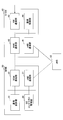
- FIG. 3 is a diagram showing a configuration example of a communication system in the embodiment of the present invention.
- the communication system according to the present embodiment includes an eNB 10, an eNB 20, an MME 30, an S-GW (Serving Gateway) 40, and a UE 50.
- FIG. 3 shows only the part related to the present embodiment regarding the core network (EPC).
- EPC core network
- the UE 50 is a user device such as a mobile phone.
- Each of the eNBs 10 and 20 is a base station.
- the MME 30 is a node device that accommodates the eNB and performs location control, mobility control such as paging and handover, bearer establishment / deletion, and the like.
- the S-GW 40 is a node device that relays user data (U-Plane data).
- the MME 30 may be referred to as a communication control device.
- the MME 30 and the S-GW 40 may be configured as a single device and referred to as a communication control device.
- the MME 30 and the eNBs 10 and 20 are connected by the S1-MME interface, and the S-GW 40 and the eNBs 10 and 20 are connected by the S1-U interface.
- a dotted connection line indicates a control signal interface, and a solid connection line indicates a user data transfer interface.
- this method is a method that enables the number of signaling to be reduced.
- Example 1 First, Example 1 will be described. As described above, in the method of the first embodiment, in addition to the conventional RRC-Idle (RRC idle state) and RRC-Connected (RRC connected state), a state called RRC-Suspended (referred to as RRC pending state) is added. Yes. In the RRC hold state, the UE and the eNB each hold the UE context used for connection in the RRC connection state before entering the RRC hold state. Then, when transitioning from the RRC hold state to the RRC connection state, RRC connection establishment is performed using the held UE context.
- RRC pending state a state called RRC-Suspended
- Example 1 Overall sequence example>
- a processing sequence when the UE 50 transitions from the RRC idle state to the RRC hold state (and the ECM hold state) will be described with reference to FIG. Since the entire processing sequence itself shown in FIG. 4 and FIG. 5 described later is disclosed in Non-Patent Document 3, an outline will be described here. Of course, the operation
- FIG. 1 A processing sequence when the UE 50 transitions from the RRC idle state to the RRC hold state (and the ECM hold state) will be described with reference to FIG. Since the entire processing sequence itself shown in FIG. 4 and FIG. 5 described later is disclosed in Non-Patent Document 3, an outline will be described here. Of course, the operation
- step 101 the eNB 10 determines to suspend the RRC connection.
- step 102 the eNB 10 transmits a message indicating that the RRC connection of the UE 50 is suspended to the MME 30. MME30 and eNB30 hold
- step 105 the MME 30 returns an Ack for step 102.
- step 106 the MME 30 enters the ECM-SUSPENDED state.
- Step 107 the eNB 10 transmits an RRC connection suspend message to the UE 50, and puts the UE 50 in the RRC suspension state (Step 108).
- the RRC connection suspend message includes Resume ID (resumption ID).
- Resume ID is an identifier used when the RRC connection is resumed next time.
- the UE 50 and the eNB 10 each store a UE context.
- the UE context held in each of the UE 50 and the eNB 10 includes, for example, an RRC configuration (RRC configuration), a bearer configuration (including bearer configuration: RoHC state information, etc.), an AS security context. (Access Stratum Security Context), L2 / L1 parameters (MAC, PHY configuration, etc.).
- RRC configuration RRC configuration
- bearer configuration including bearer configuration: RoHC state information, etc.
- AS security context Access Stratum Security Context
- L2 / L1 parameters MAC, PHY configuration, etc.
- the UE 50 and the eNB 10 may hold the same information as the UE context, the UE 50 holds only the UE context information necessary for the connection with the eNB 10, and the eNB 10 stores the UE context necessary for the connection with the UE 50. Only information may be retained.
- the UE 50 and the eNB 10 each have RadioResourceConfigDedicated information carried by RRCRRConnection Setup, capability information carried by RRC Connection Setup Complete, and security-related information (key information, etc.), RRC Security related information carried in Security Mode Command, configuration information carried in RRC Connection Reconfiguration, and the like are held as UE context. Note that these are merely examples, and information held as a UE context is not limited to these, and information may be additionally held, or part of the information may not be held.
- UE radio capability (which is described as UE capability) is information included in the UE context.
- the eNB 10 in the RRC hold state, the eNB 10 basically does not hold the UE capability.
- UE capability is not limited to UE radio capability.
- the UE 10 and the eNB 10 each retain the above information as a UE context, so that when transitioning from the RRC hold state to the RRC connection state, the RRC Connection Setup Complete, RRC Security Mode Command, RRC Security Mode Complete, RRC Connection Reconfiguration RRC connection can be established without sending / receiving messages such as RRC ConnectionRReconfiguration Complete.
- FIG. 5 shows a case where the UE 50 in the RRC hold state (step 151) receives an incoming call (steps 152 to 155).
- step 151 receives an incoming call
- steps 152 to 155 receives an incoming call
- Similar processing is performed for reusing the UE context.
- step 156 an RRC resumption procedure (resumeureprocedure) is activated from the EMM layer.
- step 157 Random Access Preamble is transmitted from the UE 50 to the eNB 10, and in step 158, Random AccessandResponse is returned from the eNB 10 to the UE 10.
- Step 159 the UE 50 transmits an RRC Connection Resume Request message to the eNB 10 as the message 3.
- the RRC Connection Resume Request message includes Resume Id (resumption ID) that is information indicating that the UE 50 holds the UE context.
- the eNB 10 that has received the RRC Connection Resume Request message obtains the UE context of the UE 50 stored in association with the Resume Id included in the message, and performs bearer resumption and the like based on the UE context information.
- the eNB 10 transmits an RRC Connection Resume Complete message including Resume Id to the UE 50.
- step 161 the UE 50 and the eNB 10 resume the stored security context. Then, in steps 162 to 165, notification of a state change of the UE 50 to the MME 30 is performed.
- Non-Patent Document 4 R3-152688
- Non-Patent Document 4 describes signaling and the like regarding S1-AP UE Context Suspend, resume as a modification to Non-Patent Document 1 (3GPP TS 36.413).
- Step 201 and Step 202 shown in FIG. 6 are executed corresponding to Step 102 and Step 105 shown in FIG.
- step 201 the eNB 10 transmits a UE context suspend request (UE context suspension request) to the MME 30.
- MME30 grasps
- step 202 the MME 30 transmits UE Context Suspend response (UE context hold response) to the eNB 10.
- the eNB 10 puts the RRC connection in a suspended state.
- Step 301 and Step 302 shown in FIG. 7 are executed corresponding to Step 162 and Step 165 shown in FIG.
- step 301 the eNB 10 transmits a UE context Resume request (UE context resumption request) to the MME 30.
- MME30 grasps
- step 302 the MME 30 transmits UE Context Resume response (UE context restart response) to the eNB 10.
- the eNB 10 acquires the UE capability from the MME 30 in an attach procedure performed when the UE 50 is powered on or a service request procedure from the UE 50 to the MME 30. If the capability of the UE 50 is not stored in the MME 30, the eNB 10 directly requests and acquires the UE 50.
- Non-Patent Document 5 An example of a procedure when the eNB 10 directly requests and acquires the UE 50 is shown in FIG. 8 (Non-Patent Document 5).
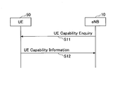
- the eNB 10 transmits UECapabilityEnquiry (UE capability information request) to the UE 50 (step 11), and the UE 50 transmits UE capability to the eNB 10 in response to the request (step 12).
- the eNB 10 transmits the UE-capability acquired from the UE 50 to the MME 30, and the MME 30 holds the UE-capability.
- UE capability is included in the UE context.
- the size of UE capability is usually several hundred bits. Therefore, if it is going to preserve
- the eNB 10 when the UE 50 transitions to the hold state while holding the UE context, deletes the UE 50 capability without saving the UE 50 capability.
- the eNB 10 erases the UE capacity of the UE 50 held in the eNB 10.
- the eNB 10 increases the capability of the UE 50 by using S1-AP UE context resume procedure (steps 162 and 165 in FIG. 5 and steps 301 and 302 in FIG. 7). get.
- the eNB 10 requests the capability of the UE 50 from the MME 30 with a UE context resume request in step 301. That is, the request information indicating that the UE context resume request requests the capability of the UE 50 is included.
- the MME 30 includes the held capability of the UE 50 in the UE context resume response in response to the request information included in the UE context resume request (step 302). Thereby, eNB10 can acquire UE capability of UE50.
- Step 301 the request information indicating that the UE 50 capability is requested is not included in the UE context resume request, and in Step 302, the MME 30 uniformly sets the UE 50 capability held by the UE context resume. It may be included in the response and transmitted to the eNB 10. In this case, UE context resume request itself corresponds to the request information.
- step 162 the eNB 10 requests the capability of the UE 50 that resumes the RRC connection from the MME 30.
- the MME 30 transmits the capability of the UE 50 that has been held to the eNB 10.
- FIG. 9 shows an example of the content of the UE context resume request message when the above processing is performed.
- FIG. 9 is based on the content added to Non-Patent Document 1 (3GPP TS 36.413) described in Non-Patent Literature 4, but the underlined portion relates to the acquisition of UE capability described above, It is not described in Non-Patent Document 4. The same applies to other diagrams showing UE-context-resume-procedure-related message contents.
- the UE-context-resume-request message includes MME-UE-S1AP-ID, eNB-UE-S1AP-ID, and S-TMSI (SAE temporary-mobile subscriber identity) as UE identifiers.
- the S-TMSI is a temporary identifier of the UE 50 generated from the unique identifier of the UE 50, and is issued from the MME 30 when the location of the UE 50 is registered.
- MME 30 since MME 30 holds UE 50 capability of UE 50 in association with S-TMSI of UE 50, MME 30 uses S-TMSI of UE 50 included in the UE context resume request message. By searching a storage unit that stores a plurality of UE capabilities, the UE ⁇ capabilities of the UE 50 can be extracted.
- S-TMSI as the UE identifier is only an example. Any identifier may be used as long as the UE ⁇ capability of the UE 50 can be extracted.
- the MME 30 may identify the UE 50 with the MME UE S1AP ID or eNB UE S1AP ID, and extract the UE capability of the UE 50.
- FIG. 10 shows an example of the content of the UE context resume response message. As shown in FIG. 10, UE capability of UE 50 extracted by MME 30 is included.
- Example 1 when UE50 changes to a hold state in the state which hold
- the MME 30 that has received UE capability (referred to as transfer UE capability) stores the transfer UE capability.
- transfer UE capability stores the transfer UE capability.
- the transfer UE-capability is already stored, for example, the transfer UE-capability is stored by overwriting the already stored UE-capability. Further, when the transfer UE-capability includes information or new information updated with respect to the already stored UE-capability, only the updated information or new information may be overwritten.
- the transfer here is not essential, but the MUE 30 can hold the latest UE capability by performing this transfer.
- FIG. 11 shows an example of the content of the UE context suspend message when the above transfer is performed. As shown in FIG. 11, UE-capability is included.
- FIG. 12 shows an example of the content of a UE context suspend response message.
- Example 2 the second embodiment does not define a new state such as RRC-Suspended.
- the UE and the eNB hold the UE context, and when the UE transitions to the RRC connected state, the held UE This is a scheme that allows the number of signaling to be reduced by reusing the context.
- the UE 50 is in an RRC connection state in the cell of the eNB 10 and is in a state in which an S1-C / U connection related to the UE 50 is established.
- the S1-C connection includes a connection between the eNB 10 and the MME 30 and a connection between the MME 30 and the S-GW 40
- the S1-U connection includes a connection between the eNB 10 and the S-GW 40.
- Non-Patent Document 5 an outline of an example of a procedure when the UE 50 first connects to the eNB 10 will be described (Non-Patent Document 5). Note that the procedure related to the first connection can also be applied to the first embodiment.
- the eNB 10 transmits RRC ⁇ Connection Setup to the UE 50, sets the UE 50 to the RRC connection state, and receives RRC Connection Setup Complete from the UE 50.
- the eNB 10 receives an Initial Context Setup Request from the MME 30, transmits an RRC Security Mode to the UE 50, receives an RRC Security Mode Complete from the UE 50, and transmits an RRC Connection Reconfiguration to the UE 50, RRC Connection Reconfiguration Complete is received from UE50, and InitialInContext Setup Response is transmitted to MME30.
- the UE context and the UE context are established and held in the UE 50 and the eNB 10. Further, the UE context is also held in the MME 30.
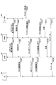
- the eNB 10 transmits a connection maintenance instruction signal to the MME 30 (step 401). Also, the MME 30 transmits a connection maintenance instruction signal to the S-GW 40 (step 402).
- the connection maintenance instruction signal is a signal that instructs the MME 30 to perform the paging by holding down the downlink data in the S-GW 40 when receiving the call to the UE 50 while maintaining the S1-C / U connection related to the UE 50.
- the S-GW 40 that has received the connection maintenance instruction signal transmits a confirmation response indicating that the instruction has been confirmed to the MME 30 (step 403), and the MME 30 transmits a confirmation response to the eNB 10 (step 404).
- connection maintenance instruction signal from the eNB 10 to the MME 30 regarding the UE 50 is triggered by, for example, the occurrence of an event that causes the UE 50 to transition to the RRC idle state in the eNB 10.
- the event that causes the transition to the RRC idle state is, for example, when it is detected that communication with the UE 50 (uplink / downlink user data communication) does not occur for a certain period of time due to expiration of a predetermined timer (eg, UE : Inactivity Timer). However, it is not limited to this.
- FIG. 13 assumes a case where it is triggered by detecting that communication with the UE 50 (uplink / downlink user data communication) does not occur for a certain period of time.
- RRC connection release RRC Connection
- Release is transmitted to the UE 50, and the UE 50 is shifted to the RRC idle state (step 405).
- Example 2 even when the UE 50 transitions to the RRC idle state, the UE context established at the time of RRC connection is maintained in each of the UE 50 and the eNB 10.
- the eNB 10 does not maintain UE capability in the UE context.
- the eNB 10 deletes the UE capability of the UE 50 held in the eNB 10.
- the eNB 10 includes the UE-capability in the connection maintenance instruction signal and transmits the connection maintenance instruction signal to the MME 30. It is good to do.
- the MME 30 that has received UE capability (referred to as transfer UE capability) stores the transfer UE capability.
- the transfer UE capability is stored by overwriting the already stored UE capability.
- the transfer UE-capability includes information or new information updated with respect to the already stored UE-capability, only the updated information or new information may be overwritten.
- downlink data for the UE 50 is generated, and the downlink data arrives at the S-GW 40 (step 406).
- the S1-U connection has been established, but based on the connection maintenance instruction signal received in step 402, the S-GW 40 holds the downlink data in the buffer without transferring it to the eNB 10.
- the S-GW 40 transmits a downlink data incoming notification to the MME 30 (step 407), and the MME 30 transmits an S1-AP paging signal for the UE 50 to the eNB 10 (step 408).
- This paging itself is the same as the existing paging, and is transmitted to each eNB in the tracking area of the UE 50, but FIG. 13 shows transmission to the eNB 10.
- the eNB 10 that has received the S1-AP paging signal transmits the RRC paging signal to the subordinate UE 50 (step 409).
- UE50 which received the RRC paging signal performs an RRC connection establishment procedure, and establishes an RRC connection (step 410).
- RRC connection establishment procedure A detailed example of the RRC connection establishment procedure will be described later.
- the UE 50 changes from the RRC idle state to the RRC connected state.
- the UE contexts held in the UE 50 and the eNB 10 change from the inactive state to the active state. That is, according to the procedure of Step 410, the UE contexts held in the UE 50 and the eNB 10 are activated.
- step 411 the eNB 10 transmits RRC connection establishment completion, which is a signal indicating that establishment of the RRC connection is completed, to the MME 30.
- This RRC connection establishment completion signal may be a signal indicating that the UE context of the UE 50 has been activated.
- the eNB 10 includes request information indicating that the UE 50 capability of the UE 50 is requested in the RRC connection establishment completion signal. Include and send.
- the request information is, for example, S-TMSI of UE 50 (an example of a UE identifier).
- the MME 30 may uniformly transmit the UE capability of the UE 50 to the eNB 10 in step 414 described later without including the request information.
- the MME 30 transmits an RRC connection establishment completion signal to the S-GW 40 (step 412).
- the S-GW 40 transmits a response signal to the RRC connection establishment completion signal to the MME 30.
- the MME 30 transmits a response signal to the signal indicating completion of RRC connection establishment in Step 411 to the eNB 10.
- the response signal in step 414 may be an Ack signal for a signal indicating that the UE context has been activated.
- the MME 30 includes request information (or a UE identifier other than the request information) included in the RRC connection establishment completion signal in Step 411. Based on this, the capability of the UE 50 that has been held is extracted, and is included in the response signal in step 414 and transmitted to the eNB 10. Thereby, eNB10 can acquire UE capability of UE50.
- the S-GW 40 starts transferring the downlink data that has been suspended to the eNB 10 (step 415).
- the downlink data reaches the UE 50 from the eNB 10 (step 416). In this way, transmission of downlink data to the UE 50 is started.
- Step 410 in FIG. 13 since the UE context established and held at the time of RRC connection in each of the UE 50 and the eNB 10 is used, the RRC Security Mode Command, RRC that was conventionally necessary is used. RRC connection establishment can be performed without transmitting / receiving messages such as Security Mode Complete, RRC Connection Reconfiguration, and RRC Connection Reconfiguration Complete.
- the UE context held in each of the UE 50 and the eNB 10 includes, for example, an RRC configuration (RRC configuration), a bearer configuration (including bearer configuration: RoHC state information, etc.), an AS security context (Access Stratum Security Context). , L2 / L1 parameters (MAC, PHY configuration, etc.).
- RRC configuration RRC configuration
- bearer configuration including bearer configuration: RoHC state information, etc.
- AS security context Access Stratum Security Context
- L2 / L1 parameters MAC, PHY configuration, etc.
- the eNB 10 prevents the UE capability from being held while the UE 50 is in the RRC idle state.
- the UE 50 and the eNB 10 may hold the same information as the UE context, the UE 50 holds only the UE context information necessary for the connection with the eNB 10, and the eNB 10 is the UE required for the connection with the UE 50. Only context information may be retained.
- the eNB 10 holds the UE context in the storage unit in association with the UE identifier (UE identifier) corresponding to the UE context.
- UE identifier UE identifier
- S-TMSI SAE temporary mobile subscriber identity
- Random Access Preamble is transmitted from the UE 50 to the eNB 10 and Random Access Response is transmitted from the eNB 10 to the UE 50 before the sequence illustrated in FIG.
- the UE 50 transmits an RRC Connection Request message (RRC connection request) to the eNB 10 in Step 501 using the resource allocated by the UL grant included in the Random Access Response.
- RRC connection request RRC connection request
- the UE 50 notifies the eNB 10 that the UE 50 holds the UE context using a spare bit (spare bit: 1 bit) in the RRC Connection Request message. For example, when the bit is set (it is 1), it indicates that the UE 50 holds the UE context. This information indicating that the UE 50 holds the UE context will be referred to as UE context holding information.
- the RRC Connection Request message includes a UE identifier for identifying the UE 50 (specifically, S-TMSI (SAE temporary mobile subscriber identity)) in addition to the above bits.
- S-TMSI is a temporary identifier of the UE 50 generated from the unique identifier of the UE 50, and is issued from the MME 30 when the location of the UE 50 is registered.
- UE50 and each eNB shall hold
- the eNB 10 that has received the RRC Connection Request message in step 501 recognizes that the UE 50 identified by the UE identifier holds the UE context by reading the UE context holding information and the UE identifier from the message, and holds it.
- the UE context corresponding to the UE identifier is retrieved from the storage means from the plurality of UE contexts that are being used. That is, UE identifier matching processing is performed.
- step 502 when the eNB 10 detects the UE context corresponding to the UE identifier as a result of the search, the eNB 10 notifies the UE 50 that the eNB 10 holds the UE context of the UE 50 by an RRC Connection Setup message (RRC connection establishment message). At the same time, the UE 50 is requested to transmit information for authenticating the UE 50.
- RRC connection establishment message RRC Connection Setup message
- the UE 50 that has received the RRC Connection Setup message including information indicating that the UE 50 holds the UE context continues to use the held UE context (bearer, security key, configuration, etc.).
- the RadioResourceConfigDedicated included in the RRC Connection Setup message includes parameter values related to the bearer, MAC, PHY configuration, etc., but the UE 50 that has received the RRC Connection Setup message including the above notification / request in Step 502 receives the RadioResourceConfigDedicated. Ignore the parameter value notified by, and continue to use the parameter value of the UE context that was held. The notified parameter value may be used without ignoring the parameter value notified by RadioResourceConfigDedicated. Thereby, when the parameter value already hold
- the UE 50 transmits to the eNB 10 the authentication information such as Authentication token and shortMAC-I in the RRC Connection Setup Complete message.
- Authentication information such as Authentication token and shortMAC-I is information used by the eNB 10 to authenticate the UE 50.
- the eNB 10 that has received the RRC Connection Setup Complete message authenticates that the UE 50 is a correct UE corresponding to the UE context searched by the UE identifier, using the authentication information included in the message. After that, each of the UE 50 and the eNB 10 establishes (restarts) a connection using the held UE context. Note that when establishing (resuming) a connection using the retained UE context, step 503 is not necessarily required, and step 503 may not be performed.
- Random Access Preamble is transmitted from the UE 50 to the eNB 10 and Random Access Response is transmitted from the eNB 10 to the UE 50 before the sequence illustrated in FIG.
- the UE 50 transmits an RRC Connection Request message (RRC connection request) to the eNB 10 in Step 501 using the resource allocated by the UL grant included in the Random Access Response.
- RRC connection request RRC Connection request
- the UE 50 transmits the authentication information included in the RRC Connection Request message.
- the authentication information is information used by the eNB 10 to authenticate the UE 50, and includes, for example, C-RNTI, PCI, and ShortMAC-I used in the previous RRC connection.
- this authentication information is also an example of UE context holding information for notifying the eNB 10 that the UE 50 holds the UE context.
- the eNB 10 that has received the RRC Connection Request message in step 501 performs authentication of the UE 50 using the authentication information, and when detecting that the authentication is successful and the UE 50 holds the UE context, On the other hand, an RRC Connection Setup message (RRC connection establishment message) including information instructing activation (activation) of the UE context held by the UE 50 is transmitted (step 502).
- RRC connection establishment message including information instructing activation (activation) of the UE context held by the UE 50 is transmitted (step 502).
- the above detection can be performed, for example, by searching the storage unit for a UE context corresponding to the UE identifier (eg, S-TMSI) from among a plurality of UE contexts that the eNB 10 holds.
- the information for instructing activation (activation) of the UE context is an example of context holding information indicating that the eNB 10 holds the UE context of the UE 50.
- the eNB 10 If the eNB 10 cannot detect that the UE context of the UE 50 is held, the eNB 10 does not include information instructing to activate (activate) the UE context held by the UE 50.
- a message (RRC connection establishment message) is transmitted to UE50.
- the UE 50 that has received the RRC Connection Setup message including information instructing activation of the UE context activates the retained UE context (bearer, security key, configuration, etc.).
- Activating means activating the retained UE context, and includes, for example, various radio resource settings, measurement settings, authentication key update processing, and the like.
- the RadioResourceConfigDedicated included in the RRC Connection Setup message may include parameter values related to bearer, MAC, PHY configuration, etc., but the UE 50 that has received the RRC Connection Setup message including the activation instruction in Step 502 receives the RadioResourceConfigDedicated.
- the parameter value notified by is applied.
- the application is made according to “5.3.105.3Radio resource configuration” in Non-Patent Document 5, for example. That is, setting is performed based on information included in RadioResourceConfigDedicated.
- the UE 50 when the UE 50 holds the information “A” in RadioResourceConfigDedicated at the time of the previous RRC connection as part of the UE context and receives the information “B” by RadioResourceConfigDedicated in Step 502, the UE 50 In addition to the information “A”, the information “B” can be used.
- the UE 50 holds information “A” in RadioResourceConfigDedicated at the time of the previous RRC connection as a part of the UE context, and in Step 502, the same type as “A” but a different value “ When “A ′” is received, the held “A” is updated (changed) by “A ′” received in step 502.
- the parameter difference between the stored RadioResourceConfigDedicated information and the RadioResourceConfigDedicated information received in Step 502 can be set. This is called delta configuration.
- step 503 the UE 50 transmits an RRC Connection Setup Complete message to the eNB 10.
- the eNB 10 when the eNB 10 causes the UE 50 to transition to the RRC idle state, the eNB 10 transmits an RRC Connection Release message to the UE 50 (step 601).
- the RRC Connection Release message includes indication information (indication) that instructs the UE 50 to continue to hold the UE context in the RRC idle state.
- indication information instructs the UE 50 to continue to hold the UE context in the RRC idle state.
- a new indication may be included in the message, or a spare bit of an existing release cause may be used.
- the UE 50 When the UE 50 detects the instruction information from the RRC Connection Release message, the UE 50 continues to hold the UE context (bearer information, security information, etc.) at the RRC idle state transition during the RRC idle state. Note that when a predetermined time is set in the UE 50 and the UE 50 transitions to the RRC idle state, and the predetermined time has elapsed in the RRC idle state, the UE 50 invalidates the held UE context. May be released (deleted).
- NB-IoT UE NearBand Internet of Things Things UE
- Low cost MTC UE Machine Type Communication UE
- NB-IoT UE communicates with a bandwidth of 180KHz or lower (minimum 3.75 or 15KHz), so the transmission speed is low.
- UEs such as NB-IoT UE and Low cost MTC UE may be collectively referred to as low-speed UEs.
- the existing LTE UE-capability is defined by nesting and expanding the parameters specified from Rel-8.
- the capability for low-speed UEs such as NB-IoT UE is added.
- an overhead is generated by defining the parameters from Rel-8 to Rel-12 by extending them. For example, when trying to specify the capability of NB-IoT UE in addition to the UE capability of Rel-12 version 12.7.0 specification, the size will be at least 17 bytes.
- FGI feature group indicators
- ⁇ ⁇ can be omitted if the UE supports all FGIs, but currently such UEs do not exist in the world, and the UE must be in F 96 A bit string of bits must be added to indicate whether each FGI is compatible (1/0).
- information indicating whether measurement gap (measurement gap) is necessary must be notified.
- PDCP parameters must be notified.
- a new UE capability is introduced for low-speed UEs such as NB-IoT UE.
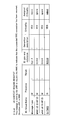
- Non-patent Document 5 Examples of changes to the specifications (Non-patent Document 5) corresponding to the UE capability are shown in FIGS. The additional part is underlined.
- FIGS. 16A and 16B show UE-CapabilityRAT-ContainerList, which is an information element included in a UE-Capability-Information message transmitted from UE 50 to eNB 10 (and MME 30).
- the UE-CapabilityRAT-ContainerList includes ueCapabilityRAT-Container for each RAT.
- UE-EUTRA-Capability-BL is added to RAT: E-UTRA.
- BL is an abbreviation for “bandwidth reduced low ⁇ complexity”, and BL UE indicates a low-speed UE such as the NB-IoT UE described above.
- FIG. 17 shows the contents of UE-EUTRA-Capability-BL.
- UE-EUTRA-Capability-BL corresponds to UE capability (UE radio capability) included in the UE Capability Information message by the low-speed UE.
- UE-EUTRA-Capability-BL is configured such that BL UE (here UE50 as an example) changes UE capability (UE Radio Access Capability Parameters) to E-UTRA (here eNB10 as an example). Used to send.
- BL UE here UE50 as an example
- UE capability UE Radio Access Capability Parameters
- the UE 50 includes a category indicating “Low Cost MTC UE” as m1 and a category indicating “NB-IoT UE” as m2 according to its own category.
- a category indicating “Low Cost MTC UE” as m1 and a category indicating “NB-IoT UE” as m2 according to its own category are examples.
- a UE having a difference in capability with respect to the default capability such as having an additional capability with respect to the default capability, notifies only the difference (eg, a parameter indicating the additional capability) in the UE-capability.
- the difference e.g, a parameter indicating the additional capability
- measurement gap is required by default for the corresponding frequency band and is not included in UE capability. Only when measurement is possible without a gap, a value indicating this is included as “GaplessMeas-r13” in FIG.
- PDCP parameters For PDCP parameters, specify default values for parameters such as ROHC profile. Only when the PDCP parameter of the UE 50 is different from the default value, the value is included in UE capability as “PDCP-Parameters-r13” in FIG.
- physical layer parameters are specified by default, and if there is any that can be handled by optional, the value is included in UE capability as “PhyLayerParameters” in FIG.
- UE 50 For the Duplex method, for the corresponding frequency band, by default, for example, only half-duplex is supported. Only when additionally supporting full-duplex, UE 50 includes a value indicating this in UE-capability as “FullDuplex-r13” in FIG.
- FIG. 18 shows an example of FGI definition newly specified for BL ⁇ UE.
- the value of FGI upportedFGIs-r13 in FIG. 17
- 103 is included.
- Example 1 and Example 2 the eNB 10 deleted the UE-capability when the UE 50 enters the hold state / idle state, but the target UE-capability is a UE-capability with a reduced size. In this case, this deletion may not be performed. This is because the problem of reducing the memory capacity related to UE ⁇ capability can be solved without deleting.
- the eNB 10 can determine that the corresponding UE-capability is a UE-capability whose size is reduced when the UE category in the UE-capability is M1 or M2. .
- the eNB 10 when the UE-capability is not deleted, the eNB 10 does not acquire the UE-capability from the MME 30 (eg, steps 162 and 165 in FIG. 5 and steps 411 and 414 in FIG. 13).
- Example 1 a configuration example of an apparatus according to the embodiment of the present invention (Example 1, Example 2, including UE capability size reduction) will be described.
- the configuration of each device described below shows only a functional unit particularly related to the embodiment of the invention, and operates as a device in a communication system compliant with at least LTE (LTE including EPC). It also has a function not shown.
- the functional configuration shown in each figure is only an example. As long as the operation according to the present embodiment can be performed, the function classification and the name of the function unit may be anything.
- Each device may include all the functions of Embodiment 1, Embodiment 2, UE capability size reduction, or may include only one of Embodiment 1 and Embodiment 2, or implementation. It is good also as providing either one of Example 1 and Example 2, and the function of UE capability size reduction. In the following description, it is assumed that each device has all the functions of Embodiment 1, Embodiment 2, and UE2capability size reduction.
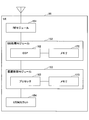
- the MME 30 includes an eNB communication unit 31, an SGW communication unit 32, a communication control unit 33, and a UE context management unit 34.
- the eNB communication unit 31 includes a function of transmitting and receiving control signals to and from the eNB through the S1-MME interface.
- the SGW communication unit 32 includes a function of transmitting / receiving control signals to / from the S-GW through the S11 interface.
- the UE context management unit 34 includes storage means for holding the UE context.
- the MME 30 receives a signal requesting UE capability from the eNB 10
- the UE context management unit 34 acquires the UE capability corresponding to the UE identifier included in the request from the storage unit, and via the eNB communication unit 31 and the like.
- the UE context management unit 34 has a function of storing the UE-capability in association with the UE identifier in the storage unit.
- the S-GW 40 includes an eNB communication unit 41, an MME communication unit 42, an NW communication unit 43, and a communication control unit 44.
- the eNB communication unit 41 includes a function of transmitting / receiving data to / from the eNB through the S1-U interface.
- the MME communication unit 42 includes a function for transmitting and receiving control signals to and from the MME through the S11 interface.
- the NW communication unit 43 includes a function of transmitting / receiving a control signal and transmitting / receiving data to / from a node device on the core NW side.
- the communication control unit 33 When the communication control unit 33 receives the connection maintenance instruction signal from the eNB 10, the communication control unit 33 instructs the SGW communication unit 32 to transmit the connection maintenance instruction signal to the S-GW, and when the confirmation response is received from the S-GW 40. And a function of instructing the eNB communication unit 31 to transmit the confirmation response to the eNB. Further, the communication control unit 33 includes a function of notifying the UE context management unit 34 of the UE capability when the UE capability is included in the connection maintenance instruction signal.
- the communication control unit 33 when the communication control unit 33 receives the RRC connection establishment completion signal from the eNB 10, the communication control unit 33 notifies the UE context management unit 34 of the RRC connection establishment completion signal, and causes the UE context management unit 34 to acquire UE capability. Moreover, when transmitting the response signal (step 414 in FIG. 13) to the eNB 10, the communication control unit 33 may have a function of including the UE capability acquired by the UE context management unit 34 in the response signal.
- the communication control unit 44 includes a function of instructing the MME communication unit 42 to transmit a confirmation response to the MME 30 when a connection maintenance instruction signal is received from the MME 30.
- the NW communication unit 43 holds the downlink data in a buffer. And a function to instruct the NW communication unit 43 to transmit the downlink data when the RRC connection establishment completion is received from the eNB.
- the MME 30 and the S-GW 40 can be configured as one device. In that case, communication of the S11 interface between the SGW communication unit 32 and the MME communication unit 42 is communication inside the apparatus.
- the MME 30 includes, for example, a CPU and a memory, and can be realized by using a computer configuration realized by executing a program by a CPU (processor).
- FIG. 20 shows an example of the hardware (HW) configuration of the MME 30 when the MME 30 is configured by a computer as described above.
- the MME 30 includes a CPU 351, a RAM (Random Access Memory) 352, a ROM (Read Only Memory) 353, a communication module 354 for performing communication, an auxiliary storage device 355 such as a hard disk, an input device 356, An output device 357 is provided.
- a CPU Central Processing Unit
- RAM Random Access Memory
- ROM Read Only Memory
- auxiliary storage device 355 such as a hard disk
- input device 356 An output device 357 is provided.
- the CPU 351 When the CPU 351 reads out and executes a program stored in a storage unit such as the RAM 352, the ROM 353, and the auxiliary storage device 355, the operation of each function of the MME 30 is executed. Further, the communication module 354 is used for processing for performing communication. Also, for example, setting information for the MME 30 can be input by the input device 356, and for example, the operating state of the MME 30 can be output by the output device 357.
- FIG. 21 shows a functional configuration diagram of the user apparatus (UE 50).
- the UE 50 includes a DL signal reception unit 51, a UL signal transmission unit 52, an RRC processing unit 53, and a UE context management unit 54.
- FIG. 21 shows only the functional units particularly related to the present invention in the UE 50, and the UE 50 also has a function (not shown) for performing an operation based on at least LTE.
- the DL signal receiving unit 51 includes a function of receiving various downlink signals from the base station eNB and acquiring higher layer information from the received physical layer signal, and the UL signal transmitting unit 52 is transmitted from the UE 50. It includes a function of generating various signals of the physical layer from information on higher layers to be transmitted and transmitting the signals to the base station eNB.
- the UE 50 is a user apparatus UE for NB-IOT, for example, and the UL signal transmission unit 52 transmits UE capability information of the user apparatus UE to the base station eNB, and the UE capability information is, for example, NB- Includes UE category for IOT and does not include FGI parameters and measurement gap parameters.
- the RRC processing unit 53 performs processing on the UE side described with reference to FIGS. 4 to 5, 8, 13 to 18, and generation / transmission of RRC messages (UE capability etc.) (transmission is UL signal transmission) Transmission through the unit 52), interpretation of the RRC message received by the DL signal receiving unit 51, processing operation based on the interpretation, and the like.
- the RRC processing unit 53 also includes a function of resuming the RRC connection using the UE context held in the UE context management unit 54.
- the UE context management unit 54 includes a storage unit such as a memory. For example, based on the instruction described in step 107 of FIG. 4, FIG. 15, etc., the UE context and UE identifier (S ⁇ TMSI etc.). Further, in the procedure shown in FIG. 14, the RRC processing unit determines whether or not the UE context is held, and if the UE context is held, the RRC processing unit notifies the information indicating that the UE context is held. 53.
- the configuration of the UE 50 shown in FIG. 21 may be entirely realized by a hardware circuit (eg, one or a plurality of IC chips), or a part is constituted by a hardware circuit, and the other part is a CPU and a program. And may be realized.
- a hardware circuit eg, one or a plurality of IC chips
- a part is constituted by a hardware circuit, and the other part is a CPU and a program. And may be realized.
- FIG. 22 is a diagram illustrating an example of the hardware (HW) configuration of the UE 50.
- FIG. 22 shows a configuration closer to the mounting example than FIG.
- the UE controls an apparatus that performs processing such as an RE (Radio Equipment) module 151 that performs processing related to a radio signal, a BB (Base Band) processing module 152 that performs baseband signal processing, and a higher layer process. It has a module 153 and a USIM slot 154 which is an interface for accessing a USIM card.
- RE Radio Equipment
- BB Base Band
- the RE module 151 should transmit from the antenna by performing D / A (Digital-to-Analog) conversion, modulation, frequency conversion, power amplification, etc. on the digital baseband signal received from the BB processing module 152 Generate a radio signal.
- a digital baseband signal is generated by performing frequency conversion, A / D (Analog to Digital) conversion, demodulation, and the like on the received wireless signal, and the digital baseband signal is passed to the BB processing module 152.
- the RE module 151 includes functions such as a physical layer in the DL signal receiving unit 51 and the UL signal transmitting unit 52 in FIG.
- the BB processing module 152 performs processing for mutually converting an IP packet and a digital baseband signal.
- a DSP (Digital Signal Processor) 162 is a processor that performs signal processing in the BB processing module 152.
- the memory 172 is used as a work area for the DSP 162.
- the BB processing module 152 includes, for example, functions such as layer 2 in the DL signal receiving unit 51 and the UL signal transmitting unit 52 in FIG. 21, an RRC processing unit 53, and a UE context management unit 54. Note that all or part of the functions of the RRC processing unit 53 and the UE context management unit 54 may be included in the device control module 153.
- the device control module 153 performs IP layer protocol processing, various application processing, and the like.
- the processor 163 is a processor that performs processing performed by the device control module 153.
- the memory 173 is used as a work area for the processor 163.
- the processor 163 reads and writes data with the USIM through the USIM slot 154.
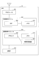
- FIG. 23 shows a functional configuration diagram of the base station eNB (eNB 10).
- the eNB 10 includes a DL signal transmission unit 11, a UL signal reception unit 12, an RRC processing unit 13, a UE context management unit 14, an authentication unit 15, and an NW communication unit 16.
- FIG. 23 shows only functional units particularly related to the embodiment of the present invention in the eNB 10, and the eNB 10 also has a function (not shown) for performing at least an operation based on the LTE scheme.
- the DL signal transmission unit 11 includes a function of generating and transmitting various physical layer signals from upper layer information to be transmitted from the eNB 10.
- the UL signal receiving unit 12 includes a function of receiving various uplink signals from the user apparatus UE and acquiring higher layer information from the received physical layer signals.
- the RRC processing unit 13 performs processing on the eNB side described with reference to FIGS. 4 to 5, 8, 13 to 18, etc., generation and transmission of an RRC message (transmission is performed via the DL signal transmission unit 11). Transmission), interpretation of the RRC message received by the UL signal reception unit 12, processing operation based on the interpretation, and the like.
- the UE context management unit 14 includes a storage unit such as a memory. For example, based on the transmission of the instruction described in step 107 of FIG. 4, FIG. 14, etc., the UE context and the UE identifier ( S-TMSI etc.).
- the UE context management unit 14 includes a function of deleting the UE capability when transitioning to the RRC hold state / RRC idle state.
- the UE context management unit 14 includes a function of storing the UE capability acquired from the MME 30 in Step 165 of FIG. 5, Step 414 of FIG.
- the authentication unit 15 includes a function of receiving authentication information from the UE and authenticating the UE in steps 501, 503, and the like illustrated in FIG.
- the NW communication unit 16 has a function of transmitting / receiving a control signal to / from the MME via the S1-MME interface, a function of transmitting / receiving data to / from the S-GW via the S1-U interface, and a function of transmitting a connection maintenance instruction signal , A transmission function for transmitting RRC connection establishment completion, and the like. That is, the NW communication unit 16 has a function of requesting UE capability from the MME 30 in step 162 of FIG. 5 and step 411 of FIG. 13, and a function of receiving UE capability from the MME 30 in step 165 of FIG. 5 and step 414 of FIG. Including.
- the configuration of the eNB 10 illustrated in FIG. 23 may be entirely realized by a hardware circuit (for example, one or a plurality of IC chips), a part is configured by a hardware circuit, and the other part is a CPU and a program. And may be realized.
- a hardware circuit for example, one or a plurality of IC chips
- a part is configured by a hardware circuit
- the other part is a CPU and a program. And may be realized.
- FIG. 24 is a diagram illustrating an example of a hardware (HW) configuration of the eNB 10.
- FIG. 24 shows a configuration closer to the mounting example than FIG.
- the eNB 10 is connected to the network by an RE module 251 that performs processing related to a radio signal, a BB processing module 252 that performs baseband signal processing, a device control module 253 that performs processing such as an upper layer, and the like.
- a communication IF 254 which is an interface for this purpose.
- the RE module 251 generates a radio signal to be transmitted from the antenna by performing D / A conversion, modulation, frequency conversion, power amplification, and the like on the digital baseband signal received from the BB processing module 252.
- a digital baseband signal is generated by performing frequency conversion, A / D conversion, demodulation, and the like on the received radio signal, and passed to the BB processing module 252.
- the RE module 251 includes functions such as a physical layer in the DL signal transmission unit 11 and the UL signal reception unit 12 in FIG.
- the BB processing module 252 performs processing for mutually converting an IP packet and a digital baseband signal.
- the DSP 262 is a processor that performs signal processing in the BB processing module 252.
- the memory 272 is used as a work area for the DSP 252.
- the BB processing module 252 includes, for example, functions such as layer 2 in the DL signal transmission unit 11 and the UL signal reception unit 12 in FIG. 23, an RRC processing unit 13, a UE context management unit 14, and an authentication unit 15. Note that all or some of the functions of the RRC processing unit 13, the UE context management unit 14, and the authentication unit 15 may be included in the device control module 253.
- the device control module 253 performs IP layer protocol processing, OAM processing, and the like.
- the processor 263 is a processor that performs processing performed by the device control module 253.
- the memory 273 is used as a work area for the processor 263.
- the auxiliary storage device 283 is an HDD, for example, and stores various setting information for the base station eNB itself to operate.
- the device control module 253 includes a function of processing a signal transmitted / received by the NW communication unit 16 of FIG.
- the communication IF 254 corresponds to a signal transmission / reception function in the NW communication unit 16 in FIG.
- the configuration (function classification) of the apparatus shown in FIGS. 19 to 24 is merely an example of a configuration that realizes the processing described in the present embodiment (Example 1, Example 2, including UE capability size reduction). Absent.
- the mounting method (specific arrangement of functional units, names, and the like) is not limited to a specific mounting method.
- the base station in the mobile communication system that supports the function of establishing connection by reusing context information held in each of the user apparatus and the base station,
- a base station is provided that includes an acquisition unit that acquires the predetermined information from a communication control apparatus that holds the predetermined information in the mobile communication system.
- the size of the context information held in the base station can be reduced. It becomes possible.
- the UE context management unit 14 of the eNB 10 is an example of a deletion unit.
- the NW communication unit 16 of the eNB 10 is an example of an acquisition unit.
- the acquisition unit may transmit a signal indicating resumption of the connection state to the communication control device and receive a response signal including the predetermined information from the communication control device.
- the signal indicating the resumption of the connection state may include an identifier of the user device, and the communication control device may extract the predetermined information based on the identifier of the user device.
- the communication control apparatus can accurately extract target information.
- the apparatus may further include a transmission unit that transmits the predetermined information to the communication control apparatus.
- a transmission unit that transmits the predetermined information to the communication control apparatus.
- the predetermined information is, for example, capability information of the user device. Since the capability information is large in size, this configuration can efficiently reduce the size of the context information that the base station should hold.
- the deletion unit may not delete the capability information, and the acquisition unit may not acquire the capability information.
- the size-reduced capability information is, for example, capability information generated so as not to include information on a capability provided by default in the user device. With this configuration, notification of unnecessary information can be avoided, and the size of capability information can be reduced.
- the user apparatus in a mobile communication system including a base station and a user apparatus for NB-IOT, the receiving unit receiving a UE capability request from the base station, and the UE capability request
- a UE that transmits UE capability information of the user apparatus to the base station in response to reception of the UE device, the UE capability information includes a UE category for NB-IOT, and includes FGI parameters and measurement gaps.
- a user device is provided that does not include parameters.
- the operations of a plurality of functional units may be physically performed by one component, or the operations of one functional unit may be physically performed by a plurality of components.
- each device has been described using a functional block diagram. However, such a device may be implemented in hardware, software, or a combination thereof.
- Software that is operated by the processor of the apparatus according to the embodiment of the present invention includes random access memory (RAM), flash memory, read only memory (ROM), EPROM, EEPROM, register, hard disk (HDD), removable disk, CD It may be stored in any suitable storage medium such as ROM, database, server, etc.
- information notification includes physical layer signaling (for example, DCI (Downlink Control Information), UCI (Uplink Control Information)), upper layer signaling (for example, RRC signaling, MAC signaling, broadcast information (MIB (Master Information Block), SIB (System Information Block))), other signals, or a combination thereof.
- RRC message may be referred to as RRC signaling.
- the RRC message may be, for example, an RRC connection setup message, an RRC connection reconfiguration message, or the like.
- Each aspect / embodiment described in this specification includes LTE (Long Term Evolution), LTE-A (LTE-Advanced), SUPER 3G, IMT-Advanced, 4G, 5G, FRA (Future Radio Access), W-CDMA.
- LTE Long Term Evolution
- LTE-A Long Term Evolution-Advanced
- SUPER 3G IMT-Advanced
- 4G 5G
- FRA Full Radio Access
- W-CDMA Wideband
- GSM registered trademark
- CDMA2000 Code Division Multiple Access 2000
- UMB User Mobile Broadband
- IEEE 802.11 Wi-Fi
- IEEE 802.16 WiMAX
- IEEE 802.20 UWB (Ultra-WideBand
- the present invention may be applied to a Bluetooth (registered trademark), a system using another appropriate system, and / or a next generation system extended based on the system.
- the determination or determination may be performed by a value represented by 1 bit (0 or 1), may be performed by a true value (Boolean: true or false), or may be performed by comparing numerical values (for example, (Comparison with a predetermined value).
- the channel and / or symbol may be a signal.
- the signal may be a message.
- UE is a subscriber station, mobile unit, subscriber unit, wireless unit, remote unit, mobile device, wireless device, wireless communication device, remote device, mobile subscriber station, access terminal, mobile terminal, wireless terminal by those skilled in the art , Remote terminal, handset, user agent, mobile client, client, or some other appropriate terminology.
- notification of predetermined information is not limited to explicitly performed, but is performed implicitly (for example, notification of the predetermined information is not performed). Also good.
- determining may encompass a wide variety of actions.
- “Judgment”, “decision” can be, for example, calculating, computing, processing, deriving, investigating, looking up (eg, table, database or another (Searching in the data structure), and confirming (ascertaining) what has been confirmed may be considered as “determining” or “determining”.
- “determination” and “determination” include receiving (for example, receiving information), transmitting (for example, transmitting information), input (input), output (output), and access. (accessing) (e.g., accessing data in a memory) may be considered as “determined” or "determined”.
- determination and “decision” means that “resolving”, “selecting”, “choosing”, “establishing”, and “comparing” are regarded as “determining” and “deciding”. May be included. In other words, “determination” and “determination” may include considering some operation as “determination” and “determination”.
- the phrase “based on” does not mean “based only on”, unless expressly specified otherwise. In other words, the phrase “based on” means both “based only on” and “based at least on.”
- the input / output information or the like may be stored in a specific place (for example, a memory) or may be managed by a management table. Input / output information and the like can be overwritten, updated, or additionally written. The output information or the like may be deleted. The input information or the like may be transmitted to another device.
- the notification of the predetermined information is not limited to explicitly performed, and may be performed implicitly (for example, notification of the predetermined information is not performed). .
Landscapes
- Engineering & Computer Science (AREA)
- Computer Networks & Wireless Communication (AREA)
- Signal Processing (AREA)
- Databases & Information Systems (AREA)
- Mobile Radio Communication Systems (AREA)
Abstract
ユーザ装置と基地局のそれぞれに保持されるコンテクスト情報を再利用して接続確立を行う機能をサポートする移動通信システムにおける前記基地局において、前記基地局が前記ユーザ装置に対応付けられたコンテクスト情報を保持した状態で、前記ユーザ装置が接続状態を終了する場合に、当該コンテクスト情報における所定の情報を削除する削除手段と、前記ユーザ装置が接続状態を再開する場合に、前記移動通信システムにおいて前記所定の情報を保持する通信制御装置から、当該所定の情報を取得する取得手段と、を備える。
Description
本発明は、移動通信システムにおけるユーザ装置UEと基地局eNBのそれぞれが、UEコンテクストを保持する技術に関連するものである。
LTEシステムにおいて、ユーザ装置UE(以下、UEと記述する)における基地局eNB(以下、eNBと記述する)との間の接続状態はRRC(Radio Resource Control)アイドル状態(RRC_Idle)と、RRC接続状態(RRC_Connected)の2つで示される。
UEがネットワークに接続する際に、UEコンテクストが生成され、RRC接続状態において、当該UEコンテクストはUEが接続するeNB及び当該UEに保持される。なお、UEコンテクストは、ベアラ関連情報、セキュリティ関連情報等を含む情報である。
UEがRRCアイドル状態とRRC接続状態との間を遷移する際に、コアNW側も含めた呼制御のシグナリングが多く発生するため、シグナリングを如何にして削減するかが課題となっている。
例えば、UEをRRC接続状態からRRCアイドル状態に遷移させる際には、図1に示すようなシグナリングが発生する(非特許文献1等)。図1のケースは、eNB2が、UE1の通信が所定時間発生しないことを検知し、UE1との接続を切断して、RRCアイドル状態に遷移させるようなケースである。
図1において、eNB2が、UEコンテクスト解放要求(UE Context Release Request)をMME3に送信する(ステップ1)。MME3は、ベアラ解放要求(Release Access Bearers Request)をS-GW4に送信し(ステップ2)、S-GW4はベアラ解放応答(Release Access Bearers Response)をMME3に返す(ステップ3)。
MME3は、UEコンテクスト解放指示(UE Context Release Command)をeNB2に送信する(ステップ4)。eNB2は、RRC接続解放(RRC Connection Release)をUE1に送信し(ステップ5)、UE1に対してUEコンテクストを解放させて、RRCアイドル状態に遷移させる。また、eNB2はUEコンテクストを解放し、UEコンテクスト解放完了(UE Context Release Complete)をMME3に送信する(ステップ6)。
3GPP TS 36.413 V12.4.0 (2014-12)
3GPP TSG RAN Meeting #66 RP-142030 Maui, USA, 8th - 11th December 2014
3GPP TR 23.720 V1.1.0(2015-10)
3GPP TSG-RAN WG3 Meeting #90 R3-152688 Anaheim, CA, U.S., 16th - 20th November 2015
3GPP TS 36.331 V12.6.0 (2015-06)
図1に示すようなシグナリング手順では、RRC接続解放時に多くのシグナリングが発生するのみならず、UEがRRCアイドル状態から再びRRC接続状態に遷移する際に、UEコンテクストの設定のために多くのシグナリングが発生する。
UEがRRCアイドル状態とRRC接続状態との間を遷移する際のシグナリングを削減するために、UEが同一eNB内でRRC接続状態‐>RRCアイドル状態->RRC接続状態と遷移する場合に、UEコンテクストをeNB及びUEで保持したままにしておき、再利用する方法が検討され始めている(非特許文献2)。当該方法において考えられる手順の例を図2を参照して説明する。
図2の(a)に示す状態は、UE1がRRC接続状態にあり、コアNW側において、当該UE1に係るS1-CのコネクションとS1-Uのコネクション(図ではS1‐C/U)が確立されている状態である。なお、S1-Cのコネクションは、C-plane信号を送るS1コネクションであり、S1-UのコネクションはU-planeを通すS1コネクションである。
(a)に示す状態から、(b)、(c)に示すように、RRC接続解放(RRC Connection Release)によりUE1がRRCアイドル状態に遷移される。このとき、eNB2におけるUE1に対するUEコンテクストは保持されたままであり、また、UE1におけるeNB2に対するUEコンテクストも保持されたままであり、UE1に対するS1‐C/Uコネクションも維持されたままである。そして、(d)に示すように、UE1がRRC接続状態に遷移する際に、eNB2とUE1は保持しておいたUEコンテクストを再利用することで、シグナリングを削減して、RRC接続を確立する。
図2に示す構成において、eNB2は、RRC接続状態のUE1とデータ送受信を行うためには、UE capability(UE1の能力情報)を取得する必要がある。UE capabilityはUEコンテクストに含められることが想定される情報であるため、図2(c)に示すように、UE1がRRCアイドル状態のときに、eNB2が保持するUEコンテクストにはUE capabilityが含められる。
しかし、UE capabilityのサイズは、通常、数百ビットにもなるため、数多くのUEのcapabilityをeNB2で保存しようとすると、大きなメモリ容量を確保する必要があり、eNB2のコスト高に繋がる。
上記のような課題は、UE capabilityに限らず、UEコンテクストとして大きなサイズの情報を保持する場合に生じ得る課題である。
本発明は上記の点に鑑みてなされたものであり、ユーザ装置と基地局のそれぞれに保持されるコンテクスト情報を再利用して接続確立を行う機能をサポートする移動通信システムにおいて、基地局が保持するコンテクスト情報のサイズを削減することを可能とする技術を提供することを目的とする。
本発明の実施の形態によれば、ユーザ装置と基地局のそれぞれに保持されるコンテクスト情報を再利用して接続確立を行う機能をサポートする移動通信システムにおける前記基地局であって、
前記基地局が前記ユーザ装置に対応付けられたコンテクスト情報を保持した状態で、前記ユーザ装置が接続状態を終了する場合に、当該コンテクスト情報における所定の情報を削除する削除手段と、
前記ユーザ装置が接続状態を再開する場合に、前記移動通信システムにおいて前記所定の情報を保持する通信制御装置から、当該所定の情報を取得する取得手段と、
を備えることを特徴とする基地局が提供される。
前記基地局が前記ユーザ装置に対応付けられたコンテクスト情報を保持した状態で、前記ユーザ装置が接続状態を終了する場合に、当該コンテクスト情報における所定の情報を削除する削除手段と、
前記ユーザ装置が接続状態を再開する場合に、前記移動通信システムにおいて前記所定の情報を保持する通信制御装置から、当該所定の情報を取得する取得手段と、
を備えることを特徴とする基地局が提供される。
また、本発明の実施の形態によれば、ユーザ装置と基地局のそれぞれに保持されるコンテクスト情報を再利用して接続確立を行う機能をサポートする移動通信システムにおける前記基地局が実行するコンテクスト情報保持方法であって、
前記基地局が前記ユーザ装置に対応付けられたコンテクスト情報を保持した状態で、前記ユーザ装置が接続状態を終了する場合に、当該コンテクスト情報における所定の情報を削除する削除ステップと、
前記ユーザ装置が接続状態を再開する場合に、前記移動通信システムにおいて前記所定の情報を保持する通信制御装置から、当該所定の情報を取得する取得ステップと、
を備えることを特徴とするコンテクスト情報保持方法が提供される。
前記基地局が前記ユーザ装置に対応付けられたコンテクスト情報を保持した状態で、前記ユーザ装置が接続状態を終了する場合に、当該コンテクスト情報における所定の情報を削除する削除ステップと、
前記ユーザ装置が接続状態を再開する場合に、前記移動通信システムにおいて前記所定の情報を保持する通信制御装置から、当該所定の情報を取得する取得ステップと、
を備えることを特徴とするコンテクスト情報保持方法が提供される。
また、本発明の実施の形態によれば、ユーザ装置と基地局のそれぞれに保持されるコンテクスト情報を再利用して接続確立を行う機能をサポートする移動通信システムにおける通信制御装置と前記基地局とが実行するコンテクスト情報保持方法であって、
前記基地局が前記ユーザ装置に対応付けられたコンテクスト情報を保持した状態で、前記ユーザ装置が接続状態を終了する場合に、前記基地局が、前記コンテクスト情報における所定の情報を削除するステップと、
前記ユーザ装置が接続状態を再開する場合に、前記基地局が、当該接続状態の再開を示す信号を前記通信制御装置に送信するステップと、
前記通信制御装置が、前記信号を受信し、前記所定の情報を含む応答信号を前記基地局に送信するステップと
を備えることを特徴とするコンテクスト情報保持方法が提供される。
前記基地局が前記ユーザ装置に対応付けられたコンテクスト情報を保持した状態で、前記ユーザ装置が接続状態を終了する場合に、前記基地局が、前記コンテクスト情報における所定の情報を削除するステップと、
前記ユーザ装置が接続状態を再開する場合に、前記基地局が、当該接続状態の再開を示す信号を前記通信制御装置に送信するステップと、
前記通信制御装置が、前記信号を受信し、前記所定の情報を含む応答信号を前記基地局に送信するステップと
を備えることを特徴とするコンテクスト情報保持方法が提供される。
本発明の実施の形態によれば、ユーザ装置と基地局のそれぞれに保持されるコンテクスト情報を再利用して接続確立を行う機能をサポートする移動通信システムにおいて、基地局が保持するコンテクスト情報のサイズを削減することを可能とする技術が提供される。
以下、図面を参照して本発明の実施の形態を説明する。なお、以下で説明する実施の形態は一例に過ぎず、本発明が適用される実施の形態は、以下の実施の形態に限られるわけではない。例えば、本実施の形態では、LTEのシステムを対象としているが、本発明はLTEに限らずに適用可能である。例えば、5Gにも適用可能である。また、本明細書及び特許請求の範囲では、特に断らない限り、「LTE」の用語は3GPPの特定のRel(リリース)に限定されない。
また、以下で説明する実施の形態では、保留/アイドル状態になったときに、eNBにおいて保持するUEコンテクストからUE capabilityを削除し、接続を再開する際に、UE capabilityをMMEから取得することとしているが、情報量削減の対象をUE capabilityとすることは一例に過ぎない。例えば、UE capabilityに代えて、もしくは、UE capabilityに加えて、RadioResourceConfigDedicatedの情報を削減の対象としてもよい。すなわち、保留/アイドル状態になったときに、eNBにおいて保持するUEコンテクストからRadioResourceConfigDedicatedの情報を削除し、接続を再開する際に、RadioResourceConfigDedicatedの情報をMMEから取得することとしてもよい。また、UE capability、RadioResourceConfigDedicated以外の情報を対象としてもよい。
(システム全体構成)
図3は、本発明の実施の形態における通信システムの構成例を示す図である。図3に示すように、本実施の形態の通信システムは、eNB10、eNB20、MME30、S-GW(Serving Gateway)40、UE50を含む。なお、図3は、コアネットワーク(EPC)に関して、本実施の形態に関連する部分のみを示している。
図3は、本発明の実施の形態における通信システムの構成例を示す図である。図3に示すように、本実施の形態の通信システムは、eNB10、eNB20、MME30、S-GW(Serving Gateway)40、UE50を含む。なお、図3は、コアネットワーク(EPC)に関して、本実施の形態に関連する部分のみを示している。
UE50は携帯電話機等のユーザ装置である。eNB10、20はそれぞれ基地局である。MME30は、eNBを収容し、位置登録、ページング、ハンドオーバ等のモビリティ制御、ベアラ確立/削除等を行うノード装置である。S-GW40は、ユーザデータ(U-Planeデータ)の中継を行うノード装置である。なお、MME30を通信制御装置と称してもよい。また、MME30とS-GW40を1つの装置で構成し、それを通信制御装置と称してもよい。
図3に示すように、MME30とeNB10、20間はS1-MMEインターフェースで接続され、S-GW40とeNB10、20間はS1-Uインターフェースで接続される。点線の接続線は制御信号インターフェースを示し、実線の接続線はユーザデータ転送のインターフェースを示す。
本実施の形態では、前述したように、UE50が同一eNB内でRRC接続状態からRRCアイドル状態に遷移する場合でも、当該eNBにおいてUE50のUEコンテクストが保持されるとともに、UE50にも当該eNBとの接続に係るUEコンテクストが保持される方式を前提とする。前述したように、この方式は、シグナリング数削減を可能とする方式である。
本実施の形態では、上記の方式の例として、非特許文献3に記載されている、RRC-Suspended(及びECM-Suspended)という新しいRRCの状態を定義する方式をベースとした実施例を実施例1として説明し、新たなRRCの状態を定義することなくUEコンテクストの再利用を行う方式をベースとした実施例を実施例2として説明する。
(実施例1)
まず、実施例1について説明する。上記のとおり、実施例1の方式では、従来のRRC-Idle(RRCアイドル状態)とRRC-Connected(RRC接続状態)に加えて、RRC-Suspended(RRC保留状態と呼ぶ)という状態が追加されている。RRC保留状態において、UEとeNBはそれぞれ、RRC保留状態になる前のRRC接続状態で接続に使用したUEコンテクストを保持する。そして、RRC保留状態からRRC接続状態に遷移するときに、当該保持したUEコンテクストを使用してRRC接続確立をする。
まず、実施例1について説明する。上記のとおり、実施例1の方式では、従来のRRC-Idle(RRCアイドル状態)とRRC-Connected(RRC接続状態)に加えて、RRC-Suspended(RRC保留状態と呼ぶ)という状態が追加されている。RRC保留状態において、UEとeNBはそれぞれ、RRC保留状態になる前のRRC接続状態で接続に使用したUEコンテクストを保持する。そして、RRC保留状態からRRC接続状態に遷移するときに、当該保持したUEコンテクストを使用してRRC接続確立をする。
<実施例1:全体シーケンス例>
まず、実施例1における通信システム全体のシーケンス例として、UE50が、RRCアイドル状態からRRC保留状態(及びECM保留状態)に遷移する場合の処理シーケンスを図4を参照して説明する。なお、図4、及び後述する図5に示す全体の処理シーケンス自体は、非特許文献3に開示されているものなので、ここでは概要を説明する。もちろん、UE capabilityに関する動作は非特許文献3に開示されていない。
まず、実施例1における通信システム全体のシーケンス例として、UE50が、RRCアイドル状態からRRC保留状態(及びECM保留状態)に遷移する場合の処理シーケンスを図4を参照して説明する。なお、図4、及び後述する図5に示す全体の処理シーケンス自体は、非特許文献3に開示されているものなので、ここでは概要を説明する。もちろん、UE capabilityに関する動作は非特許文献3に開示されていない。
ステップ101において、eNB10は、RRC接続を保留することを決定する。ステップ102において、eNB10は、UE50のRRC接続が保留されたことを示すメッセージをMME30に送信する。MME30とeNB30はUEコンテクストを保持する。
ステップ103、104でのメッセージを経て、ステップ105において、MME30はステップ102に対するAckを返す。ステップ106で、MME30はECM-SUSPENDEDの状態に入る。
ステップ107では、eNB10はUE50にRRC connection suspendメッセージを送信し、UE50をRRC保留状態にする(ステップ108)。RRC connection suspendメッセージには、Resume ID(再開ID)が含まれる。Resume IDは、次にRRC接続を再開する場合に使用される識別子である。RRC保留状態において、UE50とeNB10はそれぞれ、UEコンテクストを格納する。
ここで、本実施の形態において、UE50とeNB10のそれぞれで保持されるUEコンテクストは、例えば、RRCコンフィギュレーション(RRC configuration)、ベアラコンフィギュレーション(bearer configuration: RoHC state information等を含む)、ASセキュリティコンテクスト(Access Stratum Security Context)、L2/L1パラメータ(MAC、PHYのコンフィギュレーション等)等である。
UE50とeNB10とでUEコンテクストとして同じ情報を保持してもよいし、UE50は、eNB10との接続に必要なUEコンテクストの情報のみを保持し、eNB10は、UE50との接続に必要なUEコンテクストの情報のみを保持してもよい。
より具体的には、RRC保留状態において、例えば、UE50とeNB10はそれぞれ、RRC Connection Setupで運ばれるRadioResourceConfigDedicatedの情報、RRC Connection Setup Completeで運ばれる能力情報、及びセキュリティ関連情報(キー情報等)、 RRC Security Mode Commandで運ばれるセキュリティ関連情報、RRC Connection Reconfigurationで運ばれるコンフィギュレーション情報等を、UEコンテクストとして保持する。なお、これらは一例であり、UEコンテクストとして保持する情報は、これらに限られず、追加で情報を保持してもよいし、これらの情報の一部を保持しないこととしてもよい。
また、本実施の形態では、UE radio capability(これをUE capabilityと記述する)もUEコンテクストに含まれる情報である。ただし、後述するように、本実施の形態では、RRC保留状態において、基本的に、eNB10はUE capabilityを保持しないようにしている。また、UE capabilityはUE radio capabilityに限られるわけではない。
UE10とeNB10はそれぞれUEコンテクストとして上記のような情報を保持することで、RRC保留状態からRRC接続状態に遷移する際に、RRC Connection Setup Complete、RRC Security Mode Command、RRC Security Mode Complete、RRC Connection Reconfiguration、RRC Connection Reconfiguration Complete、等のメッセージの送受信を行うことなくRRC接続確立を行うことができる。
次に、UE50が、RRC保留状態からRRC接続状態に遷移する場合のシーケンス例を図5を参照して説明する。図5は、RRC保留状態(ステップ151)にあるUE50が着信を受ける(ステップ152~155)ケースを示しているが、これは例であり、RRC保留状態にあるUE50が発信をする場合も、UEコンテクストの再利用に関しては同様の処理が行われる。
eNB10からページングを受信したUEにおいて、ステップ156では、EMMレイヤから、RRC再開手順(resume procedure)が起動される。ステップ157にてRandom Access PreambleがUE50からeNB10に送信され、ステップ158にて、Random Access ResponseがeNB10からUE10に返される。
ステップ159では、メッセージ3として、UE50は、RRC Connection Resume RequestメッセージをeNB10に送信する。
当該RRC Connection Resume Requestメッセージには、UE50がUEコンテクストを保持することを示す情報であるResume Id(再開ID)が含まれる。RRC Connection Resume Requestメッセージを受信したeNB10は、当該メッセージに含まれるResume Idに対応付けて格納されている、UE50のUEコンテクストを取得し、UEコンテクストの情報に基づき、ベアラの再開等を行う。ステップ160では、eNB10は、UE50に対してResume Idを含むRRC Connection Resume Completeメッセージを送信する。
ステップ161では、UE50とeNB10は、格納したセキュリティコンテクストを再開する。そして、ステップ162~165において、MME30に対するUE50の状態変更の通知等が行われる。
<UEコンテクストの保留手順、再開手順について>
図4、図5を参照して説明したS1-AP UE Context Suspend, resumeに関するシグナリングの例が、例えば非特許文献4(R3-152688)に記載されている。非特許文献4には、非特許文献1(3GPP TS 36.413)に対する変更として、S1-AP UE Context Suspend, resumeに関するシグナリング等が記載されている。
図4、図5を参照して説明したS1-AP UE Context Suspend, resumeに関するシグナリングの例が、例えば非特許文献4(R3-152688)に記載されている。非特許文献4には、非特許文献1(3GPP TS 36.413)に対する変更として、S1-AP UE Context Suspend, resumeに関するシグナリング等が記載されている。
実施例1において、非特許文献4の技術を適用すると、図4に示すステップ102、ステップ105に対応して、図6に示すステップ201、ステップ202が実行される。
UEコンテクストの保留手順(UE context suspend procedure)を示す図6において、ステップ201で、eNB10はUE Context Suspend request(UEコンテクスト保留要求)をMME30に送信する。これにより、MME30は、UEコンテクストが保留状態であることを把握する。また、ステップ202により、MME30はeNB10にUE Context Suspend response(UEコンテクスト保留応答)を送信する。これにより、eNB10はRRC接続を保留状態とする。
また、実施例1において、非特許文献4の技術を適用すると、図5に示すステップ162、ステップ165に対応して、図7に示すステップ301、ステップ302が実行される。
UEコンテクストの再開手順(UE context resume procedure)を示す図7において、ステップ301で、eNB10はUE Context Resume request(UEコンテクスト再開要求)をMME30に送信する。これにより、MME30は、UEコンテクストが再開されたことを把握する。また、ステップ302により、MME30はeNB10にUE Context Resume response(UEコンテクスト再開応答)を送信する。
<UEコンテクストとしてのUE capabilityの保持/送信について>
本実施の形態におけるシステムの通常の動作として、UE50の電源ON等に実施されるアタッチ手順、あるいは、UE50からMME30へのサービス要求手順等において、eNB10はMME30からUE capabilityを取得する。もしも、MME30に当該UE50のcapabilityが保存されていない場合は、eNB10がUE50に直接要求して取得する。
本実施の形態におけるシステムの通常の動作として、UE50の電源ON等に実施されるアタッチ手順、あるいは、UE50からMME30へのサービス要求手順等において、eNB10はMME30からUE capabilityを取得する。もしも、MME30に当該UE50のcapabilityが保存されていない場合は、eNB10がUE50に直接要求して取得する。
eNB10がUE50に直接要求して取得する場合の手順の例を図8に示す(非特許文献5)。図8に示すとおり、eNB10がUE50にUECapabilityEnquiry(UE能力情報要求)を送信し(ステップ11)、当該要求に応じて、UE50がeNB10にUE capabilityを送信する(ステップ12)。eNB10は、UE50から取得したUE capabilityをMME30に送信し、MME30は当該UE capabilityを保持する。
本実施の形態ではUEコンテクストにUE capabilityが含まれる。しかし、既に説明したように、UE capabilityのサイズは、通常、数百ビットにもなる。そのため、数多くの保留状態のUEのcapabilityをUEコンテクストとしてeNB10で保存しようとすると、大きなメモリ容量を確保する必要があり、eNB10のコスト高に繋がる。
そこで、実施例1では、UE50がUEコンテクストを保持した状態で保留状態に遷移した場合、eNB10はUE50のUE capabilityを保存せず、消去する。
具体的には、図4に示すシーケンスにおいて、ステップ107で、eNB10がUE50にRRC connection suspendメッセージを送信した後、eNB10は、eNB10に保持しているUE50のUE capabilityを消去する。
また、UE50がRRC接続状態に復帰する場合には、S1-AP UE context resume procedure(図5のステップ162、165、図7でのステップ301、302)を用いることにより、eNB10はUE50のcapabilityを取得する。
具体的には、まず図7を参照して説明すると、eNB10は、ステップ301のUE context resume requestでMME30にUE50のcapabilityを要求する。つまり、UE context resume requestには、UE50のcapabilityを要求することを示す要求情報が含まれる。
MME30は、UE context resume requestに含まれる要求情報に応じて、保持していたUE50のcapabilityをUE context resume responseに含めてeNB10に送信する(ステップ302)。これにより、eNB10は、UE50のUE capabilityを取得することができる。
なお、ステップ301において、UE context resume requestの中にUE50のcapabilityを要求することを示す要求情報を含めずに、ステップ302において、一律に、MME30が、保持していたUE50のcapabilityをUE context resume responseに含めてeNB10に送信することとしてもよい。なお、この場合、UE context resume request自体が上記要求情報に該当することになる。
図5のシーケンスでは、ステップ162において、eNB10は、RRC接続を再開するUE50のcapabilityをMME30に要求する。ステップ165において、MME30は、保持していたUE50のcapabilityをeNB10に送信する。
上記の処理を行う場合におけるUE context resume requestメッセージの内容例を図9に示す。図9は、非特許文献4に記載されている、非特許文献1(3GPP TS 36.413)に対して追加される内容に基づくが、下線を引いた部分は上述したUE capabilityの取得に関連し、非特許文献4に記載されていない。UE context resume procedure関連のメッセージ内容を示す他の図も同様である。
図9に示すように、UE context resume requestメッセージには、UEの識別子として、MME UE S1AP ID、eNB UE S1AP ID、及びS-TMSI(SAE temporary mobile subscriber identity)が含まれる。S-TMSIは、UE50固有の識別子から生成される一時的なUE50の識別子であり、UE50の位置登録時等にMME30から払い出されるものである。本実施の形態において、MME30は、UE50のUE capabilityを、UE50のS-TMSIと対応付けて保持していることから、MME30は、UE context resume requestメッセージに含まれるUE50のS-TMSIを用いて、複数のUE capabilityを格納した記憶部を検索することで、UE50のUE capabilityを抽出することができる。
なお、UEの識別子としてS-TMSIを用いることは一例に過ぎない。UE50のUE capabilityを抽出することができるのであれば、どのような識別子を用いてもよい。例えば、UE context resume requestメッセージに、S-TMSIを含めずに、MME30がMME UE S1AP ID又はeNB UE S1AP IDでUE50を特定し、UE50のUE capabilityを抽出することとしてもよい。
図10は、UE context resume responseメッセージの内容例を示す。図10に示すように、MME30により抽出されたUE50のUE capabilityが含まれている。
<保留状態に遷移する際のUE capabilityの転送について>
実施例1において、UE50がUEコンテクストを保持した状態で保留状態に遷移する際に、eNB10がMME30にUE50のUE capabilityを転送することとしてもよい。具体的には、図4でのステップ102、図6でのステップ201においてUE50のUE capabilityが転送される。
実施例1において、UE50がUEコンテクストを保持した状態で保留状態に遷移する際に、eNB10がMME30にUE50のUE capabilityを転送することとしてもよい。具体的には、図4でのステップ102、図6でのステップ201においてUE50のUE capabilityが転送される。
UE capability(転送UE capabilityと呼ぶ)を受信したMME30は、転送UE capabilityを格納する。既にUE capabilityを格納している場合には、例えば、既に格納しているUE capabilityに上書きして転送UE capabilityを格納する。また、転送UE capabilityが、既に格納しているUE capabilityに対して更新された情報や新たな情報を含む場合に、当該更新された情報や新たな情報のみを上書きしてもよい。
UE capabilityは、この前の段階でアタッチ手順等においてeNB10からMME30に送信されているので、ここでの転送は必須ではないが、この転送を行うことで、最新のUE capabilityをMME30が保持できる。
図11に、上記の転送を行う場合におけるUE context suspend requestメッセージの内容例を示す。図11に示すように、UE capabilityが含められる。図12は、UE context suspend responseメッセージの内容例を示す。
(実施例2)
次に、実施例2について説明する。前述したとおり、実施例2は、RRC-Suspendedのような新しい状態を定義することなく、RRCアイドル状態において、UEとeNBがUEコンテクストを保持し、RRC接続状態に遷移する際に、保持したUEコンテクストを再利用することで、シグナリング数削減を可能とする方式である。
次に、実施例2について説明する。前述したとおり、実施例2は、RRC-Suspendedのような新しい状態を定義することなく、RRCアイドル状態において、UEとeNBがUEコンテクストを保持し、RRC接続状態に遷移する際に、保持したUEコンテクストを再利用することで、シグナリング数削減を可能とする方式である。
<全体のシーケンス例>
まず、実施例2における通信システム全体のシーケンス例として、RRCアイドル状態のUE50に対する着信がある場合に、MME30からページングを行う方式について説明する。より具体的には、UE50がeNB10に接続してRRC接続状態となり、eNB10の配下のセルでRRCアイドル状態となり、同一セルで、その後に着信を受ける場合の処理シーケンスを図13を参照して説明する。
まず、実施例2における通信システム全体のシーケンス例として、RRCアイドル状態のUE50に対する着信がある場合に、MME30からページングを行う方式について説明する。より具体的には、UE50がeNB10に接続してRRC接続状態となり、eNB10の配下のセルでRRCアイドル状態となり、同一セルで、その後に着信を受ける場合の処理シーケンスを図13を参照して説明する。
図13の処理の前提として、UE50はeNB10のセルにおいてRRC接続状態にあり、UE50に関するS1-C/Uのコネクションが確立されている状態とする。図13において、S1-Cコネクションは、eNB10とMME30との間のコネクションとMME30とS-GW40間のコネクションを含み、S1-Uコネクションは、eNB10とS-GW40間のコネクションを含む。コネクションが確立されている場合、コネクション確立信号等のコネクションセットアップのための手順を実行することなく、該当ノード装置間でUE50に係る信号(データ)を送受信できる。
図13の手順の説明に入る前に、UE50が最初にeNB10に接続する際の手順の一例の概要を説明しておく(非特許文献5)。なお、この最初の接続に係る手順は、実施例1にも適用できる。UE50のランダムアクセス時に、eNB10は、RRC Connection SetupをUE50に送信し、UE50をRRC接続状態とし、UE50からRRC Connection Setup Completeを受信する。その後、eNB10は、MME30からInitial Context Setup Requestを受信し、UE50に対してRRC Security Mode Commandを送信し、UE50からRRC Security Mode Completeを受信し、また、UE50に対してRRC Connection Reconfigurationを送信し、UE50からRRC Connection Reconfiguration Completeを受信し、MME30に対してInitial Context Setup Responseを送信する。このような手順を経て、UE50とeNB10におけるUEコンテクストの確立、保持等がなされる。また、MME30にもUEコンテクストが保持される。
図13に示すように、RRC接続状態において、eNB10はMME30に対してコネクション維持指示信号を送信する(ステップ401)。また、MME30はコネクション維持指示信号をS-GW40に送信する(ステップ402)。
コネクション維持指示信号は、当該UE50に関するS1-C/Uコネクションを維持しながら、UE50への着信時に下りデータをS-GW40に保留して、MME30からページングを行うことを指示する信号である。
コネクション維持指示信号を受信したS-GW40は、指示を確認したことを示す確認応答をMME30に送信し(ステップ403)、MME30は、確認応答をeNB10に送信する(ステップ404)。
UE50に関するeNB10からMME30へのコネクション維持指示信号の送信は、例えば、eNB10において、UE50をRRCアイドル状態に遷移させる事象が発生したことをトリガーとして行う。
上記のRRCアイドル状態に遷移させる事象とは、例えば、所定のタイマ(例:UE Inactivity Timer)の満了によって、UE50との通信(上り下りのユーザデータ通信)が一定時間発生しないことを検知した場合であるが、これに限られるわけではない。
図13は、UE50との通信(上り下りのユーザデータ通信)が一定時間発生しないことを検知したことをトリガーとする場合を想定しており、ステップ401~404の後に、RRC接続解放(RRC Connection Release)をUE50に送信し、UE50をRRCアイドル状態に遷移させる(ステップ405)。
実施例2では、UE50が、RRCアイドル状態に遷移する場合でも、UE50とeNB10のそれぞれにおいて、RRC接続時に確立したUEコンテクストは保持される。
ただし、実施例1と同様に、基本的に、eNB10はUEコンテクストのうち、UE capabilityを保持しないようにしている。
よって、図4でのステップ107の後のUE capability消去と同様に、図13のステップ405(RRC Connection Release送信)の後、eNB10は、eNB10に保持しているUE50のUE capabilityを消去する。
また、実施例1で、保留状態に遷移する際にUE capabilityを転送する場合と同様に、eNB10は、ステップ401において、コネクション維持指示信号にUE capabilityを含め、当該コネクション維持指示信号をMME30に送信することとしてもよい。
UE capability(転送UE capabilityと呼ぶ)を受信したMME30は、転送UE capabilityを格納する。既にUE capabilityを格納している場合には、例えば、既に格納しているUE capabilityを上書きして転送UE capabilityを格納する。また、転送UE capabilityが、既に格納しているUE capabilityに対して更新された情報や新たな情報を含む場合に、当該更新された情報や新たな情報のみを上書きしてもよい。
その後、UE50向けの下りデータが発生し、当該下りデータがS-GW40に到着する(ステップ406)。ここでは、S1-Uコネクションは確立済みであるが、ステップ402で受信したコネクション維持指示信号に基づき、S-GW40は、当該下りデータをeNB10に転送せずにバッファに保留しておく。
S-GW40は、下りデータ着信通知をMME30に送信し(ステップ407)、MME30はUE50向けのS1-APページングの信号をeNB10に送信する(ステップ408)。このページング自体は、既存のページングと同様であり、UE50のトラッキングエリアの各eNBに送信されるが、図13ではeNB10への送信を示している。
S1-APページングの信号を受信したeNB10は、配下のUE50にRRCページングの信号を送信する(ステップ409)。
RRCページング信号を受信したUE50は、RRC接続確立手順を実行し、RRC接続を確立させる(ステップ410)。RRC接続確立手順の詳細例は後述する。
ステップ410の手順により、UE50は、RRCアイドル状態からRRC接続状態になる。このとき、UE50とeNB10に保持されているUEコンテクストは、それぞれ、非アクティブ状態からアクティブ状態になる。つまり、ステップ410の手順により、UE50とeNB10に保持されているUEコンテクストは、それぞれ、アクティベートされる。
ステップ411において、eNB10は、RRC接続の確立が完了したことを示す信号であるRRC接続確立完了をMME30に送信する。このRRC接続確立完了の信号は、UE50のUEコンテクストがアクティベートされたことを示す信号であってもよい。
また、実施例1での図5のステップ162、図7でのステップ301と同様に、ステップ411において、eNB10はRRC接続確立完了の信号に、UE50のUE capabilityを要求することを示す要求情報を含めて送信する。当該要求情報は、例えば、UE50のS-TMSI(UE識別子の一例)である。実施例1の場合と同様に、当該要求情報を含めずに、一律に、MME30が後述するステップ414でUE50のUE capabilityをeNB10に送信することとしてもよい。
MME30はRRC接続確立完了の信号をS-GW40に送信する(ステップ412)。
そして、ステップ413において、S-GW40は、RRC接続確立完了の信号に対する応答の信号をMME30に送信する。また、ステップ414において、MME30は、ステップ411のRRC接続確立完了の信号に対する応答の信号をeNB10に送信する。ステップ414における応答の信号は、UEコンテクストがアクティベートされたことを示す信号に対するAckの信号であってもよい。
また、実施例1での図5のステップ165、図7でのステップ302と同様に、MME30は、ステップ411のRRC接続確立完了の信号に含まれる要求情報(あるいは要求情報以外のUE識別子)に基づき、保持していたUE50のcapabilityを抽出し、これをステップ414の応答信号に含めてeNB10に送信する。これにより、eNB10は、UE50のUE capabilityを取得することができる。
その後、S-GW40は保留していた下りデータのeNB10への転送を開始する(ステップ415)。当該下りデータはeNB10からUE50に届く(ステップ416)。このようにしてUE50への下りデータの伝送が開始される。
図13のステップ410のRRC接続確立手順では、UE50とeNB10のそれぞれでRRC接続時に確立し、保持しておいたUEコンテクストが利用されるので、従来は必要であった、RRC Security Mode Command、RRC Security Mode Complete、RRC Connection Reconfiguration、RRC Connection Reconfiguration Complete、等のメッセージの送受信を行うことなくRRC接続確立を行うことができる。
ここで、UE50とeNB10のそれぞれで保持されるUEコンテクストは、例えば、RRCコンフィギュレーション(RRC configuration)、ベアラコンフィギュレーション(bearer configuration: RoHC state information等を含む)、ASセキュリティコンテクスト(Access Stratum Security Context)、L2/L1パラメータ(MAC、PHYのコンフィギュレーション等)等である。また、UE capabilityもUEコンテクストに含まれるが、上述したように、eNB10は、UE50がRRCアイドル状態中において、UE capabilityを保持しないようにしている。
また、UE50とeNB10とでUEコンテクストとして同じ情報を保持してもよいし、UE50は、eNB10との接続に必要なUEコンテクストの情報のみを保持し、eNB10は、UE50との接続に必要なUEコンテクストの情報のみを保持してもよい。
また、実施例2では、eNB10は、UEコンテクストを、当該UEコンテクストに対応するUEの識別子(UE識別子)に対応付けて記憶手段に保持する。UE識別子の種類には限定はないが、実施例2では、一例として、UE識別子としてS-TMSI(SAE temporary mobile subscriber identity)を使用している。
<RRC接続確立手順の例>
次に、実施例2におけるUE50とeNB10との間のRRC接続確立手順について、図14のシーケンスを参照して説明する。なお、図14に示すシーケンスは、図13のステップ410の手順を想定しているが、これに限られない。例えば、図14に示すシーケンスが、UE50からの発信時のRRC接続確立手順におけるものであってもよい。
次に、実施例2におけるUE50とeNB10との間のRRC接続確立手順について、図14のシーケンスを参照して説明する。なお、図14に示すシーケンスは、図13のステップ410の手順を想定しているが、これに限られない。例えば、図14に示すシーケンスが、UE50からの発信時のRRC接続確立手順におけるものであってもよい。
図14に示すシーケンスの前に、UE50からeNB10にRandom Access Preambleが送信され、eNB10からUE50にRandom Access Responseが送信されているとする。
UE50は、Random Access Responseに含まれるULグラントで割り当てられるリソースにより、ステップ501において、RRC Connection Requestメッセージ(RRC接続要求)をeNB10に送信する。実施例2では、ステップ501において、UE50は、RRC Connection Requestメッセージにおけるスペアビット(spare bit :1ビット)を使用して、UE50がUEコンテテクストを保持していることをeNB10に通知する。例えば、ビットが立っている(1である)場合に、UE50はUEコンテクストを保持していることを示す。UE50がUEコンテクストを保持していることを示すこの情報をUEコンテクスト保持情報と呼ぶことにする。
また、RRC Connection Requestメッセージには、上記のビットに加えて、UE50を識別するUE識別子(具体的には、S-TMSI(SAE temporary mobile subscriber identity ))が含まれる。S-TMSIは、UE50固有の識別子から生成される一時的なUE50の識別子であり、UE50の位置登録時等にMME30から払い出されるものである。本実施の形態では、UE50と各eNBは、UE50を識別するためのS-TMSIを保持しているものとする。
ステップ501で上記RRC Connection Requestメッセージを受信したeNB10は、当該メッセージからUEコンテクスト保持情報とUE識別子を読み出すことで、UE識別子で識別されるUE50がUEコンテクストを保持していることを認識し、保持している複数のUEコンテクストの中から、当該UE識別子に対応するUEコンテクストを記憶手段から検索する。すなわち、UE識別子のマッチング処理を行う。
ステップ502において、eNB10は、検索の結果、UE識別子に対応するUEコンテクストを検出すると、RRC Connection Setupメッセージ(RRC接続確立メッセージ)により、eNB10がUE50のUEコンテクストを保持していることをUE50に通知するとともに、UE50の認証のための情報を送信するようにUE50に要求する。
UE50のUEコンテクストを保持していることを示す情報が含まれるRRC Connection Setupメッセージを受信したUE50は、保持していたUEコンテクスト(ベアラ、security key、コンフィギュレーション等)を継続使用する。
また、RRC Connection Setupメッセージに含まれるRadioResourceConfigDedicatedには、ベアラ、MAC及びPHYコンフィギュレーション等に関するパラメータ値が含まれるが、ステップ502において上記の通知・要求を含むRRC Connection Setupメッセージを受信したUE50は、RadioResourceConfigDedicatedにより通知されるパラメータ値を無視し、保持していたUEコンテクストのパラメータ値を継続使用する。なお、RadioResourceConfigDedicatedにより通知されるパラメータ値を無視せずに、通知されたパラメータ値を使用することとしてもよい。これにより、既に保持しているパラメータ値がeNB10により変更された場合に、その変更を反映することができる。
次に、ステップ503において、UE50は、RRC Connection Setup Completeメッセージに、Authentication token、shortMAC-I等の認証情報を含めてeNB10に送信する。Authentication token、shortMAC-I等の認証情報は、eNB10がUE50を認証するために使用される情報である。
RRC Connection Setup Completeメッセージを受信したeNB10は、当該メッセージに含まれる認証情報を使用して、UE50が、UE識別子により検索されたUEコンテクストに対応する正しいUEであることを認証する。その後、UE50とeNB10はそれぞれ、保持していたUEコンテクストを利用して接続を確立(再開)する。なお、保持していたUEコンテクストを利用して接続を確立(再開)するにあたって、ステップ503は必ずしも必須ではなく、ステップ503を実施しないこととしてもよい。
<RRC接続確立手順の変形例>
変形例のRRC接続確立手順におけるシーケンス自体は、図14に示したシーケンスと同じであるので、図14を参照してRRC接続確立手順の変形例について説明する。変形例においても、図14に示すシーケンスは、図13のステップ410の手順を想定しているが、これに限られない。
変形例のRRC接続確立手順におけるシーケンス自体は、図14に示したシーケンスと同じであるので、図14を参照してRRC接続確立手順の変形例について説明する。変形例においても、図14に示すシーケンスは、図13のステップ410の手順を想定しているが、これに限られない。
図14に示すシーケンスの前に、UE50からeNB10にRandom Access Preambleが送信され、eNB10からUE50にRandom Access Responseが送信されているとする。
UE50は、Random Access Responseに含まれるULグラントで割り当てられるリソースにより、ステップ501において、RRC Connection Requestメッセージ(RRC接続要求)をeNB10に送信する。変形例では、ステップ501において、UE50は、UEコンテクストを保持している場合に、認証情報をRRC Connection Requestメッセージに含めて送信する。当該認証情報は、eNB10がUE50を認証するために使用される情報であり、例えば、前回のRRC接続で使用したC-RNTI、PCI、及びShortMAC-Iを含む。
また、この認証情報は、UE50がUEコンテテクストを保持していることをeNB10に通知するためのUEコンテクスト保持情報の例でもある。
ステップ501で上記RRC Connection Requestメッセージを受信したeNB10は、認証情報を用いてUE50の認証を行い、認証に成功し、かつ、UE50のUEコンテクストを保持していることを検知した場合に、UE50に対し、UE50が保持しているUEコンテクストをアクティベート(アクティブ化)することを指示する情報を含むRRC Connection Setupメッセージ(RRC接続確立メッセージ)を送信する(ステップ502)。上記の検知は、例えば、eNB10が、保持している複数のUEコンテクストの中から、UE識別子(例:S-TMSI)に対応するUEコンテクストを記憶手段から検索することにより行うことができる。なお、UEコンテクストをアクティベート(アクティブ化)することを指示する情報は、eNB10がUE50のUEコンテクストを保持していることを示すコンテクスト保持情報の例である。
eNB10がUE50のUEコンテクストを保持していることを検知できなかった場合には、eNB10は、UE50が保持しているUEコンテクストをアクティベート(アクティブ化)することを指示する情報を含まないRRC Connection Setupメッセージ(RRC接続確立メッセージ)をUE50に送信する。
UEコンテクストをアクティベートすることを指示する情報が含まれるRRC Connection Setupメッセージを受信したUE50は、保持していたUEコンテクスト(ベアラ、security key、コンフィギュレーション等)をアクティベートする。アクティベートするとは、保持していたUEコンテクストを有効化することであり、例えば、各種無線リソースの設定、測定設定、認証キーの更新処理等を含む。
また、RRC Connection Setupメッセージに含まれるRadioResourceConfigDedicatedには、ベアラ、MAC及びPHYコンフィギュレーション等に関するパラメータ値が含まれ得るが、ステップ502において上記のアクティベート指示を含むRRC Connection Setupメッセージを受信したUE50は、RadioResourceConfigDedicatedにより通知されるパラメータ値を適用する。適用は、例えば、非特許文献5における「5.3.10 Radio resource configuration」に従ってなされる。つまり、RadioResourceConfigDedicatedに含まれる情報に基づく設定を行う。
一例として、UE50が、UEコンテクストの一部として、前回のRRC接続時のRadioResourceConfigDedicatedにおける「A」という情報を保持していて、ステップ502においてRadioResourceConfigDedicatedにより「B」という情報を受信した場合、UE50は、「A」という情報に加えて、「B」という情報を使用できる。
また、UE50が、UEコンテクストの一部として、前回のRRC接続時のRadioResourceConfigDedicatedにおける「A」という情報を保持していて、ステップ502においてRadioResourceConfigDedicatedにより、「A」と同じ種類であるが値の異なる「A´」を受信した場合、保持していた「A」は、ステップ502で受信した「A´」により更新(変更)される。
つまり、上記の処理により、保存していたRadioResourceConfigDedicatedの情報と、ステップ502において受信したRadioResourceConfigDedicatedの情報とのパラメータ差分の設定を行うことができる。これをdelta configurationと呼ぶ。
次に、ステップ503において、UE50は、RRC Connection Setup CompleteメッセージをeNB10に送信する。
<RRC接続解放手順の例>
実施例2においては、UE50がeNB10からRRC Connection Releaseメッセージを受信してRRCアイドル状態に遷移する際に、常にUEコンテクストを保持することとしてもよいし、RRC Connection Releaseメッセージ内にUEコンテクストを保持することを指示する情報が含まれていた場合にのみUEコンテクストを保持することとしてもよい。後者の例を以下に説明する。
実施例2においては、UE50がeNB10からRRC Connection Releaseメッセージを受信してRRCアイドル状態に遷移する際に、常にUEコンテクストを保持することとしてもよいし、RRC Connection Releaseメッセージ内にUEコンテクストを保持することを指示する情報が含まれていた場合にのみUEコンテクストを保持することとしてもよい。後者の例を以下に説明する。
図15に示すように、eNB10がUE50をRRCアイドル状態に遷移させる場合に、eNB10はUE50に対してRRC Connection Releaseメッセージを送信する(ステップ601)。
当該RRC Connection Releaseメッセージには、RRCアイドル状態においてUEコンテクストを保持し続けることをUE50に指示する指示情報(indication)が含まれる。なお、指示情報については、新規のindicationをメッセージ中に含めても良いし、既存のrelease causeのスペアビットを用いることとしてもよい。
UE50は、RRC Connection Releaseメッセージから上記指示情報を検知した場合、RRCアイドル状態の間、RRCアイドル状態遷移時のUEコンテクスト(ベアラ情報,セキュリティ情報等)を保持し続ける。なお、所定の時間をUE50に設定し、UE50がRRCアイドル状態に遷移した時点から、RRCアイドル状態のままで当該所定の時間が経過した場合には、UE50は、保持しているUEコンテクストを無効として、これを解放(削除)してもよい。
(UE Capabilityのサイズ削減について)
以下、本実施の形態におけるUE Capabilityのサイズ削減について説明する。ここで説明する事項は、実施例1、実施例2のいずれにも適用可能である。
以下、本実施の形態におけるUE Capabilityのサイズ削減について説明する。ここで説明する事項は、実施例1、実施例2のいずれにも適用可能である。
今後、NB-IoT UE(NarrowBand Internet of Things UE)やLow cost MTC UE(Machine Type Communication UE)のような、一般的な携帯端末よりも機能が限定された端末が増加することが考えられる。
例えば、NB-IoT UEは、上り180KHz以下(最低3.75 or 15KHz)の帯域幅で通信するため、伝送速度が低い。以下、便宜上、NB-IoT UEやLow cost MTC UE等のUEを総称して低速度UEと呼ぶ場合がある。
一方、既存のLTE UE capabilityはRel-8から規定されているパラメータを入れ子に拡張する形で規定されており、既存のLTE UE capabilityに追加でNB-IoT UE等の低速度UE向けのcapabilityを規定すると、Rel-8からRel-12までのパラメータを拡張して定義することによるオーバーヘッドが発生する。例えば,Rel-12 version 12.7.0仕様のUE capabilityに追加でNB-IoT UEのcapabilityを規定しようとすると、最低でも17 bytesの大きさになる。
既存のLTE UE capabilityには、mandatoryで含まれるパラメータ(含めることが必須であるパラメータ)が幾つかあり、それらがUE capabilityのサイズ増加の一要因になっている。
例えば、FGI (feature group indicators) については、UEが全てのFGIに対応していれば省略できるが、現状そのようなUEは世の中に存在しておらず、UEは、UE capabilityに必ずFGIの96ビットのビット列を付加し、各FGIの対応有無(1/0)を通知しなければならない。また、Measurement gap(測定ギャップ)の必要性有無を示す情報も必ず通知する必要がある。更に、PDCPのパラメータも必ず通知する必要がある。
そこで、本実施の形態では、NB-IoT UE等の低速度UE向けに新しいUE capabilityを導入する。
当該UE capabilityに対応する仕様書(非特許文献5)の変更例を図16~図18に示す。追加部分には下線が引かれている。
図16A、Bは、UE50からeNB10(及びMME30)に送信されるUE Capability Informationメッセージに含められる情報要素であるUE-CapabilityRAT-ContainerListを示す。UE-CapabilityRAT-ContainerListは、RAT毎にueCapabilityRAT-Containerを含む。本実施の形態では、RAT:E-UTRAに対し、UE-EUTRA-Capability-BLが追加されている。BLは、「bandwidth reduced low complexity」の略であり、BL UEは、上述したNB-IoT UE等の低速度UEを示す。
図17は、UE-EUTRA-Capability-BLの内容を示す。UE-EUTRA-Capability-BLは、低速度UE がUE Capability Informationメッセージに含めるUE capability (UE radio capability)に相当する。
図17に記載されているとおり、UE-EUTRA-Capability-BLは、BL UE(ここでは例としてUE50)が、UE capability (UE Radio Access Capability Parameters)をE-UTRA (ここでは例としてeNB10)に送信するために使用される。
図17に示すUE-EUTRA-Capability-BLの情報要素の内容について、UEカテゴリ(ue-Category)に関しては、既存のUEカテゴリは含めずに、新たに定めたBL UE用のUEカテゴリのみを含める。例えば、UE50は、自身のカテゴリに応じて、m1として「Low Cost MTC UE」を示すカテゴリを含め、m2として「NB-IoT UE」を示すカテゴリを含める。ただし、これらは一例である。
既存技術においてmandatoryであるFGI、PDCPパラメータ、measurement gapに関しては、デフォルトの能力を規定しておき、パラメータとしてシグナリングしない。すなわち、デフォルトの情報についてはUE capabilityに含めない。BL UEは機能が限定されているため、全てのBL UEが持つべき最低限の機能を想定し良い。このように全てのBL UEが持つと考えられる機能(能力)がデフォルトの能力として規定される。
デフォルトの能力に対して追加の能力を持つ等、デフォルトの能力に対して能力の差分を有するUEは、当該差分(例:追加の能力を示すパラメータ)のみをUE capabilityに含めて通知する。このような差分の通知を可能とすることで、BL UEに実装する機能に柔軟性を持たせることができる。
より具体的に、例えば、measurement gapは対応する周波数バンドに対してデフォルトで必要とし、UE capabilityに含めない。gap無でmeasurement可能である場合のみ、図17における「GaplessMeas-r13」として、そのことを示す値を含める。
PDCPパラメータに関しては、ROHC profileといったパラメータのデフォルト値を規定する。そして、UE50のPDCPパラメータが、デフォルト値と異なる場合にのみ図17における「PDCP-Parameters-r13」として、UE capabilityにその値を含める。
また、物理レイヤパラメータについて、デフォルトで規定し、optionalで対応可能なものがあれば、図17における「PhyLayerParameters」として、UE capabilityにその値を含める。
3G、GERAN等の他RATの対応能力については、例えばデフォルトで無しとし、対応可能な他RATがある場合のみ、図17における「interRAT-Parameters-r13」として、UE capabilityにその値を含める。
Duplex方式に関し、対応する周波数バンドに対して、デフォルトでは、例えばhalf duplex対応のみとする。UE50は、追加でfull duplexに対応する場合のみ、図17における「FullDuplex-r13」として、UE capabilityに、そのことを示す値を含める。
図18は、BL UE用に新たに規定するFGIの定義の例を示す。図18に示す例において、例えば、Rel-10対応のUE50が、カテゴリM1を通知する場合に、FDDとTDDの両方に対応している場合には、FGIの値(図17のupportedFGIs-r13)として、例えば103を含める。
<UE capabilityサイズ削減を行う場合の実施例1、実施例2の動作について>
上記のようなサイズの削減されたUE capabilityを用いる場合でも、実施例1、実施例2における動作は既に説明したものから変更しないこととしてもよいし、以下に示すように変更してもよい。
上記のようなサイズの削減されたUE capabilityを用いる場合でも、実施例1、実施例2における動作は既に説明したものから変更しないこととしてもよいし、以下に示すように変更してもよい。
すなわち、実施例1、実施例2において、eNB10は、UE50が保留状態/アイドル状態になる際に、UE capabilityを削除していたが、対象とするUE capabilityがサイズの削減されたUE capabilityである場合には、この削除を行わないこととしてもよい。削除しなくても、UE capabilityに関するメモリ容量削減の課題を解決できるからである。サイズの削減されたUE capabilityであるか否かについては、例えば、eNB10は、UE capabilityにおけるUEカテゴリがM1又はM2である場合に、該当UE capabilityはサイズの削減されたUE capabilityであると判断できる。
また、上記のように、UE capabilityの削除を行わない場合は、eNB10はMME30からのUE capabilityの取得(例:図5のステップ162、165、図13のステップ411、414)を行わない。
(装置構成例)
次に、本発明の実施の形態(実施例1、実施例2、UE capabilityサイズ削減を含む)における装置の構成例を説明する。以下で説明する各装置の構成は、発明の実施の形態に特に関連する機能部のみを示すものであり、少なくともLTE(EPCを含む意味のLTE)に準拠した通信システムにおける装置として動作するための図示しない機能も有するものである。また、各図に示す機能構成は一例に過ぎない。本実施の形態に係る動作を実行できるのであれば、機能区分や機能部の名称はどのようなものでもよい。
次に、本発明の実施の形態(実施例1、実施例2、UE capabilityサイズ削減を含む)における装置の構成例を説明する。以下で説明する各装置の構成は、発明の実施の形態に特に関連する機能部のみを示すものであり、少なくともLTE(EPCを含む意味のLTE)に準拠した通信システムにおける装置として動作するための図示しない機能も有するものである。また、各図に示す機能構成は一例に過ぎない。本実施の形態に係る動作を実行できるのであれば、機能区分や機能部の名称はどのようなものでもよい。
各装置は、実施例1、実施例2、UE capabilityサイズ削減の全ての機能を備えてもよいし、実施例1と実施例2のうちのいずれか一方のみを備えることとしてもよいし、実施例1と実施例2のうちのいずれか一方とUE capabilityサイズ削減の機能を備えることとしてもよい。以下の説明では、各装置は実施例1、実施例2、UE capabilityサイズ削減の全ての機能を備えるものとする。
<MME、S-GWの構成例>
まず、図19を参照して、MME30とS-GW40の構成例を説明する。図19に示すように、MME30は、eNB通信部31、SGW通信部32、通信制御部33、UEコンテクスト管理部34を含む。
まず、図19を参照して、MME30とS-GW40の構成例を説明する。図19に示すように、MME30は、eNB通信部31、SGW通信部32、通信制御部33、UEコンテクスト管理部34を含む。
eNB通信部31は、eNBとの間でS1-MMEインターフェースによる制御信号の送受信を行う機能を含む。SGW通信部32は、S-GWとの間でS11インターフェースによる制御信号の送受信を行う機能を含む。UEコンテクスト管理部34は、UEコンテクストを保持する記憶手段を含む。また、UEコンテクスト管理部34は、MME30がeNB10からUE capabilityを要求する信号を受信した場合に、要求に含まれるUE識別子に対応するUE capabilityを記憶手段から取得し、eNB通信部31等を介してeNB10に送信する機能を含む。また、UEコンテクスト管理部34は、MME30がeNB10からUE capabilityを受信した際に、当該UE capabilityをUE識別子と対応付けて記憶手段に格納する機能を有する。
また、S-GW40は、eNB通信部41、MME通信部42、NW通信部43、通信制御部44を含む。eNB通信部41は、eNBとの間でS1-Uインターフェースによるデータの送受信を行う機能を含む。MME通信部42は、MMEとの間でS11インターフェースによる制御信号の送受信を行う機能を含む。NW通信部43は、コアNW側のノード装置との間で制御信号の送受信及びデータの送受信を行う機能を含む。
なお、ここまでの説明は実施例1と実施例2で共通である。以下では特に、実施例2についての機能を説明する。
通信制御部33は、eNB10からコネクション維持指示信号を受信した場合に、コネクション維持指示信号をS-GWに送信するようSGW通信部32に指示するとともに、S-GW40から確認応答を受信した場合に、当該確認応答をeNBに送信するようeNB通信部31に指示する機能を含む。また、通信制御部33は、コネクション維持指示信号にUE capabilityが含まれている場合、UE capabilityをUEコンテクスト管理部34に通知する機能を含む。
また、通信制御部33は、RRC接続確立完了信号をeNB10から受信した場合において、RRC接続確立完了信号をUEコンテクスト管理部34に通知し、UEコンテクスト管理部34にUE capabilityを取得させる。また、通信制御部33は、応答信号(図13のステップ414)をeNB10に送信する際に、UEコンテクスト管理部34により取得されたUE capabilityを応答信号に含める機能も有することとしてもよい。
通信制御部44は、MME30からコネクション維持指示信号を受信した場合に、確認応答をMME30に送信するようMME通信部42に指示する機能を含む。また、通信制御部44は、MME30からコネクション維持指示信号を受信している場合において、該当UEへの下りデータを受信した場合に、当該下りデータをバッファに保留しておくようにNW通信部43に指示し、RRC接続確立完了をeNBから受信した場合に、当該下りデータを送信するようにNW通信部43に指示する機能を含む。
なお、MME30とS-GW40を1つの装置として構成することもできる。その場合、SGW通信部32とMME通信部42間のS11インターフェースの通信は、装置内部の通信となる。
MME30は、例えば、CPUとメモリを備え、プログラムがCPU(プロセッサ)により実行されることで実現されるコンピュータの構成を用いて実現できる。
上記のようなコンピュータによりMME30を構成する場合におけるMME30のハードウェア(HW)構成の例を図20に示す。
図20に示すように、当該MME30は、CPU351、RAM(Random Access Memory)352、ROM(Read Only Memory)353、通信を行うための通信モジュール354、ハードディスク等の補助記憶装置355、入力装置356、出力装置357を備える。
RAM352、ROM353、補助記憶装置355等の記憶手段に格納されたプログラムをCPU351が読み出し、実行することにより、MME30の各機能の動作が実行される。また、通信を行う処理については、通信モジュール354が使用される。また、入力装置356により、例えば、MME30に対する設定情報の入力を行い、出力装置357により、例えば、MME30の稼働状態の出力等を行うことができる。
次に、本発明の実施の形態におけるUE50とeNB10の構成例を説明する。
<ユーザ装置UE>
図21に、ユーザ装置(UE50)の機能構成図を示す。図21に示すように、UE50は、DL信号受信部51、UL信号送信部52、RRC処理部53、UEコンテクスト管理部54を備える。なお、図21は、UE50において本発明に特に関連する機能部のみを示すものであり、UE50は、少なくともLTEに準拠した動作を行うための図示しない機能も有するものである。
図21に、ユーザ装置(UE50)の機能構成図を示す。図21に示すように、UE50は、DL信号受信部51、UL信号送信部52、RRC処理部53、UEコンテクスト管理部54を備える。なお、図21は、UE50において本発明に特に関連する機能部のみを示すものであり、UE50は、少なくともLTEに準拠した動作を行うための図示しない機能も有するものである。
DL信号受信部51は、基地局eNBから各種の下り信号を受信し、受信した物理レイヤの信号からより上位のレイヤの情報を取得する機能を含み、UL信号送信部52は、UE50から送信されるべき上位のレイヤの情報から、物理レイヤの各種信号を生成し、基地局eNBに対して送信する機能を含む。また、UE50は、例えばNB-IOT用のユーザ装置UEであり、UL信号送信部52は、当該ユーザ装置UEのUE能力情報を基地局eNBに送信し、当該UE能力情報は、例えば、NB-IOT用のUEカテゴリを含み、FGIのパラメータ及び測定ギャップのパラメータを含まない。
RRC処理部53は、図4~図5、図8、図13~図18等を参照して説明した、UE側の処理、RRCメッセージ(UE capability等)の生成・送信(送信はUL信号送信部52を介した送信)、DL信号受信部51により受信したRRCメッセージの解釈、解釈に基づく処理動作等を行う。また、RRC処理部53は、UEコンテクスト管理部54に保持しておいたUEコンテクストを利用してRRC接続を再開する機能等も含む。
UEコンテクスト管理部54は、メモリ等の記憶手段を含み、例えば、図4のステップ107、図15等で説明した指示に基づいて、RRC保留状態/RRCアイドル状態においてUEコンテクスト及びUE識別子(S-TMSI等)を保持する。また、図14に示す手順においては、UEコンテクストの保持の有無を判断し、UEコンテクストを保持している場合には、UEコンテクストを保持していることを示す情報を通知するよう、RRC処理部53に指示する。
図21に示すUE50の構成は、全体をハードウェア回路(例:1つ又は複数のICチップ)で実現してもよいし、一部をハードウェア回路で構成し、その他の部分をCPUとプログラムとで実現してもよい。
図22は、UE50のハードウェア(HW)構成の例を示す図である。図22は、図21よりも実装例に近い構成を示している。図22に示すように、UEは、無線信号に関する処理を行うRE(Radio Equipment)モジュール151と、ベースバンド信号処理を行うBB(Base Band)処理モジュール152と、上位レイヤ等の処理を行う装置制御モジュール153と、USIMカードにアクセスするインタフェースであるUSIMスロット154とを有する。
REモジュール151は、BB処理モジュール152から受信したデジタルベースバンド信号に対して、D/A(Digital-to-Analog)変換、変調、周波数変換、及び電力増幅等を行うことでアンテナから送信すべき無線信号を生成する。また、受信した無線信号に対して、周波数変換、A/D(Analog to Digital)変換、復調等を行うことでデジタルベースバンド信号を生成し、BB処理モジュール152に渡す。REモジュール151は、例えば、図21のDL信号受信部51及びUL信号送信部52における物理レイヤ等の機能を含む。
BB処理モジュール152は、IPパケットとデジタルベースバンド信号とを相互に変換する処理を行う。DSP(Digital Signal Processor)162は、BB処理モジュール152における信号処理を行うプロセッサである。メモリ172は、DSP162のワークエリアとして使用される。BB処理モジュール152は、例えば、図21のDL信号受信部51及びUL信号送信部52におけるレイヤ2等の機能、RRC処理部53及びUEコンテクスト管理部54を含む。なお、RRC処理部53及びUEコンテクスト管理部54の機能の全部又は一部を装置制御モジュール153に含めることとしてもよい。
装置制御モジュール153は、IPレイヤのプロトコル処理、各種アプリケーションの処理等を行う。プロセッサ163は、装置制御モジュール153が行う処理を行うプロセッサである。メモリ173は、プロセッサ163のワークエリアとして使用される。また、プロセッサ163は、USIMスロット154を介してUSIMとの間でデータの読出し及び書込みを行う。
<基地局eNB>
図23に、基地局eNB(eNB10)の機能構成図を示す。図23に示すように、eNB10は、DL信号送信部11、UL信号受信部12、RRC処理部13、UEコンテクスト管理部14、認証部15、NW通信部16を備える。なお、図23は、eNB10において本発明の実施の形態に特に関連する機能部のみを示すものであり、eNB10は、少なくともLTE方式に準拠した動作を行うための図示しない機能も有するものである。
図23に、基地局eNB(eNB10)の機能構成図を示す。図23に示すように、eNB10は、DL信号送信部11、UL信号受信部12、RRC処理部13、UEコンテクスト管理部14、認証部15、NW通信部16を備える。なお、図23は、eNB10において本発明の実施の形態に特に関連する機能部のみを示すものであり、eNB10は、少なくともLTE方式に準拠した動作を行うための図示しない機能も有するものである。
DL信号送信部11は、eNB10から送信されるべき上位のレイヤの情報から、物理レイヤの各種信号を生成し、送信する機能を含む。UL信号受信部12は、ユーザ装置UEから各種の上り信号を受信し、受信した物理レイヤの信号からより上位のレイヤの情報を取得する機能を含む。
RRC処理部13は、図4~図5、図8、図13~図18等を参照して説明した、eNB側の処理、RRCメッセージの生成・送信(送信はDL信号送信部11を介した送信)、UL信号受信部12により受信したRRCメッセージの解釈、解釈に基づく処理動作等を行う。
UEコンテクスト管理部14は、メモリ等の記憶手段を含み、例えば、図4のステップ107、図14等で説明した指示の送信に基づいて、RRC保留状態/RRCアイドル状態においてUEコンテクスト及びUE識別子(S-TMSI等)を保持する。また、UEコンテクスト管理部14は、RRC保留状態/RRCアイドル状態に遷移した際にUE capabilityの削除を行う機能を含む。また、対象UE capabilityが、サイズの削減されたUE capabilityかどうかを判断し、サイズの削減されたUE capabilityである場合に、削除を行わないこととしてもよい。また、UEコンテクスト管理部14は、図5のステップ165、図13のステップ414等においてMME30から取得したUE capabilityを記憶手段に格納する機能を含む。
認証部15は、図14に示したステップ501、503等において、UEから認証情報を受信し、UEの認証を行う機能を含む。
NW通信部16は、S1-MMEインターフェースでMMEとの間で制御信号を送受信する機能、及び、S1-UインターフェースでS-GWとの間でデータを送受信する機能、コネクション維持指示信号の送信機能、RRC接続確立完了の送信の送信機能等を含む。すなわち、NW通信部16は、図5のステップ162、図13のステップ411においてMME30にUE capabilityを要求する機能、図5のステップ165、図13のステップ414においてMME30からUE capabilityを受信する機能を含む。
図23に示すeNB10の構成は、全体をハードウェア回路(例:1つ又は複数のICチップ)で実現してもよいし、一部をハードウェア回路で構成し、その他の部分をCPUとプログラムとで実現してもよい。
図24は、eNB10のハードウェア(HW)構成の例を示す図である。図24は、図23よりも実装例に近い構成を示している。図24に示すように、eNB10は、無線信号に関する処理を行うREモジュール251と、ベースバンド信号処理を行うBB処理モジュール252と、上位レイヤ等の処理を行う装置制御モジュール253と、ネットワークと接続するためのインタフェースである通信IF254とを有する。
REモジュール251は、BB処理モジュール252から受信したデジタルベースバンド信号に対して、D/A変換、変調、周波数変換、及び電力増幅等を行うことでアンテナから送信すべき無線信号を生成する。また、受信した無線信号に対して、周波数変換、A/D変換、復調等を行うことでデジタルベースバンド信号を生成し、BB処理モジュール252に渡す。REモジュール251は、例えば、図23のDL信号送信部11及びUL信号受信部12における物理レイヤ等の機能を含む。
BB処理モジュール252は、IPパケットとデジタルベースバンド信号とを相互に変換する処理を行う。DSP262は、BB処理モジュール252における信号処理を行うプロセッサである。メモリ272は、DSP252のワークエリアとして使用される。BB処理モジュール252は、例えば、図23のDL信号送信部11及びUL信号受信部12におけるレイヤ2等の機能、RRC処理部13、UEコンテクスト管理部14、認証部15を含む。なお、RRC処理部13、UEコンテクスト管理部14、認証部15の機能の全部又は一部を装置制御モジュール253に含めることとしてもよい。
装置制御モジュール253は、IPレイヤのプロトコル処理、OAM処理等を行う。プロセッサ263は、装置制御モジュール253が行う処理を行うプロセッサである。メモリ273は、プロセッサ263のワークエリアとして使用される。補助記憶装置283は、例えばHDD等であり、基地局eNB自身が動作するための各種設定情報等が格納される。
また、装置制御モジュール253は、図23のNW通信部16により送受信する信号の処理を行う機能を含む。通信IF254は、図23のNW通信部16における信号送受信の機能に相当する。
なお、図19~図24に示す装置の構成(機能区分)は、本実施の形態(実施例1、実施例2、UE capabilityサイズ削減を含む)で説明する処理を実現する構成の一例に過ぎない。本実施の形態で説明する処理を実現できるのであれば、その実装方法(具体的な機能部の配置、名称等)は、特定の実装方法に限定されない。
(実施の形態のまとめ)
以上、説明したように、本実施の形態により、ユーザ装置と基地局のそれぞれに保持されるコンテクスト情報を再利用して接続確立を行う機能をサポートする移動通信システムにおける前記基地局であって、前記基地局が前記ユーザ装置に対応付けられたコンテクスト情報を保持した状態で、前記ユーザ装置が接続状態を終了する場合に、当該コンテクスト情報における所定の情報を削除する削除手段と、前記ユーザ装置が接続状態を再開する場合に、前記移動通信システムにおいて前記所定の情報を保持する通信制御装置から、当該所定の情報を取得する取得手段と、を備える基地局が提供される。
以上、説明したように、本実施の形態により、ユーザ装置と基地局のそれぞれに保持されるコンテクスト情報を再利用して接続確立を行う機能をサポートする移動通信システムにおける前記基地局であって、前記基地局が前記ユーザ装置に対応付けられたコンテクスト情報を保持した状態で、前記ユーザ装置が接続状態を終了する場合に、当該コンテクスト情報における所定の情報を削除する削除手段と、前記ユーザ装置が接続状態を再開する場合に、前記移動通信システムにおいて前記所定の情報を保持する通信制御装置から、当該所定の情報を取得する取得手段と、を備える基地局が提供される。
上記の構成により、ユーザ装置と基地局のそれぞれに保持されるコンテクスト情報を再利用して接続確立を行う機能をサポートする移動通信システムにおいて、基地局が保持するコンテクスト情報のサイズを削減することが可能となる。なお、eNB10のUEコンテクスト管理部14は、削除手段の例である。また、eNB10のNW通信部16は、取得手段の例である。
前記取得手段は、前記接続状態の再開を示す信号を前記通信制御装置に送信し、前記所定の情報を含む応答信号を前記通信制御装置から受信することとしてもよい。このようにして所定の情報を取得することで、例えば、図5に示すような信号の送受信を行う方式において、新たな信号を加えることなく、効率的に本発明を適用できる。
前記接続状態の再開を示す信号には、前記ユーザ装置の識別子が含まれ、前記通信制御装置は、当該ユーザ装置の識別子に基づき前記所定の情報を抽出することとしてもよい。本構成により、通信制御装置は正確に目的の情報を抽出できるようになる。
前記ユーザ装置が接続状態を終了する場合に、前記所定の情報を前記通信制御装置に送信する送信手段を更に備えてもよい。この構成により、例えば、何らかの理由で通信制御装置が前記所定の情報を保持していない場合であっても、接続状態の再開時に、前記所定の情報を取得できる。
前記所定の情報は、例えば、前記ユーザ装置の能力情報である。能力情報のサイズは大きいので、この構成により、効率的に、基地局が保持すべきコンテクスト情報のサイズを削減できる。
前記所定の情報が、サイズの削減された能力情報である場合に、前記削除手段は、当該能力情報の削除を行わず、前記取得手段は、当該能力情報の取得を行わないこととしてもよい。この構成により、基地局が保持すべきコンテクスト情報のサイズを削減できるとともに、シグナリングシーケンスを削減できる。
前記サイズの削減された能力情報は、例えば、前記ユーザ装置においてデフォルトで備えられる能力についての情報を含まないように生成された能力情報である。この構成により、不必要な情報を通知することを回避して、能力情報のサイズ削減を実現できる。
なお、上記の各装置の構成における「手段」を、「部」、「回路」、「デバイス」等に置き換えてもよい。
また、本実施の形態により、基地局とNB-IOT用のユーザ装置とを含む移動通信システムにおける前記ユーザ装置であって、前記基地局からUE能力要求を受信する受信部と、前記UE能力要求の受信に応じて、前記ユーザ装置のUE能力情報を前記基地局に送信する送信部と、を備え、前記UE能力情報は、NB-IOT用のUEカテゴリを含み、FGIのパラメータ及び測定ギャップのパラメータを含まないことを特徴とするユーザ装置が提供される。
以上、本発明の実施の形態を説明してきたが、開示される発明はそのような実施形態に限定されず、当業者は様々な変形例、修正例、代替例、置換例等を理解するであろう。発明の理解を促すため具体的な数値例を用いて説明がなされたが、特に断りのない限り、それらの数値は単なる一例に過ぎず適切な如何なる値が使用されてもよい。上記の説明における項目の区分けは本発明に本質的ではなく、2以上の項目に記載された事項が必要に応じて組み合わせて使用されてよいし、ある項目に記載された事項が、別の項目に記載された事項に(矛盾しない限り)適用されてよい。機能ブロック図における機能部又は処理部の境界は必ずしも物理的な部品の境界に対応するとは限らない。複数の機能部の動作が物理的には1つの部品で行われてもよいし、あるいは1つの機能部の動作が物理的には複数の部品により行われてもよい。説明の便宜上、各装置は機能的なブロック図を用いて説明されたが、そのような装置はハードウェアで、ソフトウェアで又はそれらの組み合わせで実現されてもよい。本発明の実施の形態に従って当該装置が有するプロセッサにより動作するソフトウェアは、ランダムアクセスメモリ(RAM)、フラッシュメモリ、読み取り専用メモリ(ROM)、EPROM、EEPROM、レジスタ、ハードディスク(HDD)、リムーバブルディスク、CD-ROM、データベース、サーバその他の適切な如何なる記憶媒体に保存されてもよい。
<実施形態の補足>
情報の通知は、本明細書で説明した態様/実施形態に限られず、他の方法で行われてもよい。例えば、情報の通知は、物理レイヤシグナリング(例えば、DCI(Downlink Control Information)、UCI(Uplink Control Information))、上位レイヤシグナリング(例えば、RRCシグナリング、MACシグナリング、ブロードキャスト情報(MIB(Master Information Block)、SIB(System Information Block)))、その他の信号又はこれらの組み合わせによって実施されてもよい。また、RRCメッセージは、RRCシグナリングと呼ばれてもよい。また、RRCメッセージは、例えば、RRC接続セットアップ(RRC Connection Setup)メッセージ、RRC接続再構成(RRC Connection Reconfiguration)メッセージなどであってもよい。
情報の通知は、本明細書で説明した態様/実施形態に限られず、他の方法で行われてもよい。例えば、情報の通知は、物理レイヤシグナリング(例えば、DCI(Downlink Control Information)、UCI(Uplink Control Information))、上位レイヤシグナリング(例えば、RRCシグナリング、MACシグナリング、ブロードキャスト情報(MIB(Master Information Block)、SIB(System Information Block)))、その他の信号又はこれらの組み合わせによって実施されてもよい。また、RRCメッセージは、RRCシグナリングと呼ばれてもよい。また、RRCメッセージは、例えば、RRC接続セットアップ(RRC Connection Setup)メッセージ、RRC接続再構成(RRC Connection Reconfiguration)メッセージなどであってもよい。
本明細書で説明した各態様/実施形態は、LTE(Long Term Evolution)、LTE-A(LTE-Advanced)、SUPER 3G、IMT-Advanced、4G、5G、FRA(Future Radio Access)、W-CDMA(登録商標)、GSM(登録商標)、CDMA2000、UMB(Ultra Mobile Broadband)、IEEE 802.11(Wi-Fi)、IEEE 802.16(WiMAX)、IEEE 802.20、UWB(Ultra-WideBand)、Bluetooth(登録商標)、その他の適切なシステムを利用するシステム及び/又はこれらに基づいて拡張された次世代システムに適用されてもよい。
判定又は判断は、1ビットで表される値(0か1か)によって行われてもよいし、真偽値(Boolean:trueまたはfalse)によって行われてもよいし、数値の比較(例えば、所定の値との比較)によって行われてもよい。
なお、本明細書で説明した用語及び/又は本明細書の理解に必要な用語については、同一の又は類似する意味を有する用語と置き換えてもよい。例えば、チャネル及び/又はシンボルは信号(シグナル)であってもよい。また、信号はメッセージであってもよい。
UEは、当業者によって、加入者局、モバイルユニット、加入者ユニット、ワイヤレスユニット、リモートユニット、モバイルデバイス、ワイヤレスデバイス、ワイヤレス通信デバイス、リモートデバイス、モバイル加入者局、アクセス端末、モバイル端末、ワイヤレス端末、リモート端末、ハンドセット、ユーザエージェント、モバイルクライアント、クライアント、またはいくつかの他の適切な用語で呼ばれる場合もある。
本明細書で説明した各態様/実施形態は単独で用いてもよいし、組み合わせて用いてもよいし、実行に伴って切り替えて用いてもよい。また、所定の情報の通知(例えば、「Xであること」の通知)は、明示的に行うものに限られず、暗黙的(例えば、当該所定の情報の通知を行わない)ことによって行われてもよい。
本明細書で使用する「判断(determining)」、「決定(determining)」という用語は、多種多様な動作を包含する場合がある。「判断」、「決定」は、例えば、計算(calculating)、算出(computing)、処理(processing)、導出(deriving)、調査(investigating)、探索(looking up)(例えば、テーブル、データベースまたは別のデータ構造での探索)、確認(ascertaining)した事を「判断」「決定」したとみなす事などを含み得る。また、「判断」、「決定」は、受信(receiving)(例えば、情報を受信すること)、送信(transmitting)(例えば、情報を送信すること)、入力(input)、出力(output)、アクセス(accessing)(例えば、メモリ中のデータにアクセスすること)した事を「判断」「決定」したとみなす事などを含み得る。また、「判断」、「決定」は、解決(resolving)、選択(selecting)、選定(choosing)、確立(establishing)、比較(comparing)などした事を「判断」「決定」したとみなす事を含み得る。つまり、「判断」「決定」は、何らかの動作を「判断」「決定」したとみなす事を含み得る。
本明細書で使用する「に基づいて」という記載は、別段に明記されていない限り、「のみに基づいて」を意味しない。言い換えれば、「に基づいて」という記載は、「のみに基づいて」と「に少なくとも基づいて」の両方を意味する。
また、本明細書で説明した各態様/実施形態の処理手順、シーケンスなどは、矛盾の無い限り、順序を入れ替えてもよい。例えば、本明細書で説明した方法については、例示的な順序で様々なステップの要素を提示しており、提示した特定の順序に限定されない。
入出力された情報等は特定の場所(例えば、メモリ)に保存されてもよいし、管理テーブルで管理してもよい。入出力される情報等は、上書き、更新、または追記され得る。出力された情報等は削除されてもよい。入力された情報等は他の装置へ送信されてもよい。
所定の情報の通知(例えば、「Xであること」の通知)は、明示的に行うものに限られず、暗黙的(例えば、当該所定の情報の通知を行わない)ことによって行われてもよい。
本明細書で説明した情報、信号などは、様々な異なる技術のいずれかを使用して表されてもよい。例えば、上記の説明全体に渡って言及され得るデータ、命令、コマンド、情報、信号、ビット、シンボル、チップなどは、電圧、電流、電磁波、磁界若しくは磁性粒子、光場若しくは光子、又はこれらの任意の組み合わせによって表されてもよい。
本発明は上記実施形態に限定されず、本発明の精神から逸脱することなく、様々な変形例、修正例、代替例、置換例等が本発明に包含される。
本特許出願は2016年1月7日に出願した日本国特許出願第2016-002128号に基づきその優先権を主張するものであり、日本国特許出願第2016-002128号の全内容を本願に援用する。
10、20 eNB
11 DL信号送信部
12 UL信号受信部
13 RRC処理部
14 UEコンテクスト管理部
15 認証部
16 NW通信部
30 MME
31 eNB通信部
32 SGW通信部
33 通信制御部
34 UEコンテクスト管理部
40 S-GW
41 eNB通信部
42 MME通信部
43 NW通信部
44 通信制御部
50 UE
51 DL信号受信部
52 UL信号送信部
53 RRC処理部
54 UEコンテクスト管理部
151 REモジュール
152 BB処理モジュール
153 装置制御モジュール
154 USIMスロット
251 REモジュール
252 BB処理モジュール
253 装置制御モジュール
254 通信IF
351 CPU
352 RAM
353 ROM
354 通信モジュール
355 補助記憶装置
356 入力装置
357 出力装置
11 DL信号送信部
12 UL信号受信部
13 RRC処理部
14 UEコンテクスト管理部
15 認証部
16 NW通信部
30 MME
31 eNB通信部
32 SGW通信部
33 通信制御部
34 UEコンテクスト管理部
40 S-GW
41 eNB通信部
42 MME通信部
43 NW通信部
44 通信制御部
50 UE
51 DL信号受信部
52 UL信号送信部
53 RRC処理部
54 UEコンテクスト管理部
151 REモジュール
152 BB処理モジュール
153 装置制御モジュール
154 USIMスロット
251 REモジュール
252 BB処理モジュール
253 装置制御モジュール
254 通信IF
351 CPU
352 RAM
353 ROM
354 通信モジュール
355 補助記憶装置
356 入力装置
357 出力装置
Claims (10)
- ユーザ装置と基地局のそれぞれに保持されるコンテクスト情報を再利用して接続確立を行う機能をサポートする移動通信システムにおける前記基地局であって、
前記基地局が前記ユーザ装置に対応付けられたコンテクスト情報を保持した状態で、前記ユーザ装置が接続状態を終了する場合に、当該コンテクスト情報における所定の情報を削除する削除手段と、
前記ユーザ装置が接続状態を再開する場合に、前記移動通信システムにおいて前記所定の情報を保持する通信制御装置から、当該所定の情報を取得する取得手段と、
を備えることを特徴とする基地局。 - 前記取得手段は、前記接続状態の再開を示す信号を前記通信制御装置に送信し、前記所定の情報を含む応答信号を前記通信制御装置から受信する
ことを特徴とする請求項1に記載の基地局。 - 前記接続状態の再開を示す信号には、前記ユーザ装置の識別子が含まれ、前記通信制御装置は、当該ユーザ装置の識別子に基づき前記所定の情報を抽出する
ことを特徴とする請求項2に記載の基地局。 - 前記ユーザ装置が接続状態を終了する場合に、前記所定の情報を前記通信制御装置に送信する送信手段
を更に備えることを特徴とする請求項1ないし3のうちいずれか1項に記載の基地局。 - 前記所定の情報は、前記ユーザ装置の能力情報である
ことを特徴とする請求項1ないし4のうちいずれか1項に記載の基地局。 - 前記所定の情報が、サイズの削減された能力情報である場合に、前記削除手段は、当該能力情報の削除を行わず、前記取得手段は、当該能力情報の取得を行わない
ことを特徴とする請求項5に記載の基地局。 - 前記サイズの削減された能力情報は、前記ユーザ装置においてデフォルトで備えられる能力についての情報を含まない
ことを特徴とする請求項6に記載の基地局。 - ユーザ装置と基地局のそれぞれに保持されるコンテクスト情報を再利用して接続確立を行う機能をサポートする移動通信システムにおける前記基地局が実行するコンテクスト情報保持方法であって、
前記基地局が前記ユーザ装置に対応付けられたコンテクスト情報を保持した状態で、前記ユーザ装置が接続状態を終了する場合に、当該コンテクスト情報における所定の情報を削除する削除ステップと、
前記ユーザ装置が接続状態を再開する場合に、前記移動通信システムにおいて前記所定の情報を保持する通信制御装置から、当該所定の情報を取得する取得ステップと、
を備えることを特徴とするコンテクスト情報保持方法。 - ユーザ装置と基地局のそれぞれに保持されるコンテクスト情報を再利用して接続確立を行う機能をサポートする移動通信システムにおける通信制御装置と前記基地局とが実行するコンテクスト情報保持方法であって、
前記基地局が前記ユーザ装置に対応付けられたコンテクスト情報を保持した状態で、前記ユーザ装置が接続状態を終了する場合に、前記基地局が、前記コンテクスト情報における所定の情報を削除するステップと、
前記ユーザ装置が接続状態を再開する場合に、前記基地局が、当該接続状態の再開を示す信号を前記通信制御装置に送信するステップと、
前記通信制御装置が、前記信号を受信し、前記所定の情報を含む応答信号を前記基地局に送信するステップと
を備えることを特徴とするコンテクスト情報保持方法。 - 基地局とNB-IOT用のユーザ装置とを含む移動通信システムにおける前記ユーザ装置であって、
前記基地局からUE能力要求を受信する受信部と、
前記UE能力要求の受信に応じて、前記ユーザ装置のUE能力情報を前記基地局に送信する送信部と、を備え、
前記UE能力情報は、NB-IOT用のUEカテゴリを含み、FGIのパラメータ及び測定ギャップのパラメータを含まない
ことを特徴とするユーザ装置。
Priority Applications (5)
| Application Number | Priority Date | Filing Date | Title |
|---|---|---|---|
| ES17736027T ES2812273T3 (es) | 2016-01-07 | 2017-01-06 | Estación base, aparato de usuario, y métodos de transmisión de información de capacidad |
| US16/066,375 US11206529B2 (en) | 2016-01-07 | 2017-01-06 | User apparatus for retaining context information |
| CN201780003852.8A CN108353451B (zh) | 2016-01-07 | 2017-01-06 | 终端、基站、移动通信系统及能力信息发送方法 |
| EP17736027.8A EP3337285B1 (en) | 2016-01-07 | 2017-01-06 | Base station, user apparatus, and capability information transmission methods |
| CONC2018/0008234A CO2018008234A2 (es) | 2016-01-07 | 2018-08-03 | Estación base, aparato de usuario y método de retener información de contexto |
Applications Claiming Priority (2)
| Application Number | Priority Date | Filing Date | Title |
|---|---|---|---|
| JP2016002128A JP6144369B1 (ja) | 2016-01-07 | 2016-01-07 | 基地局、及びコンテクスト情報保持方法 |
| JP2016-002128 | 2016-01-07 |
Publications (1)
| Publication Number | Publication Date |
|---|---|
| WO2017119490A1 true WO2017119490A1 (ja) | 2017-07-13 |
Family
ID=59012165
Family Applications (1)
| Application Number | Title | Priority Date | Filing Date |
|---|---|---|---|
| PCT/JP2017/000294 Ceased WO2017119490A1 (ja) | 2016-01-07 | 2017-01-06 | 基地局、ユーザ装置、及びコンテクスト情報保持方法 |
Country Status (7)
| Country | Link |
|---|---|
| US (1) | US11206529B2 (ja) |
| EP (1) | EP3337285B1 (ja) |
| JP (1) | JP6144369B1 (ja) |
| CN (1) | CN108353451B (ja) |
| CO (1) | CO2018008234A2 (ja) |
| ES (1) | ES2812273T3 (ja) |
| WO (1) | WO2017119490A1 (ja) |
Cited By (2)
| Publication number | Priority date | Publication date | Assignee | Title |
|---|---|---|---|---|
| JP2019036920A (ja) * | 2017-08-21 | 2019-03-07 | アンリツ株式会社 | 移動端末試験装置および移動端末試験方法 |
| WO2019099694A1 (en) * | 2017-11-15 | 2019-05-23 | Qualcomm Incorporated | Methods and apparatus to reduce ue capability information message size |
Families Citing this family (16)
| Publication number | Priority date | Publication date | Assignee | Title |
|---|---|---|---|---|
| EP3445127B1 (en) * | 2016-05-13 | 2020-11-25 | Kyocera Corporation | Wireless terminal |
| US10764953B2 (en) | 2016-05-18 | 2020-09-01 | Telefonaktiebolaget Lm Ericsson (Publ) | Methods of resuming a radio bearer and related wireless terminals and network nodes |
| US10356837B2 (en) * | 2016-09-29 | 2019-07-16 | Acer Incorporated | State transitioning method and electronic device using the same |
| CN107889241B (zh) * | 2016-09-30 | 2020-03-06 | 电信科学技术研究院 | 一种终端能力协商方法、终端及基站 |
| CN109005680B (zh) * | 2017-04-06 | 2022-05-24 | 北京小米移动软件有限公司 | 实现物联网设备引导的方法、装置、设备及基站 |
| WO2018195855A1 (zh) * | 2017-04-27 | 2018-11-01 | 北京小米移动软件有限公司 | 一种信令传输方法及装置 |
| EP4593520A3 (en) * | 2017-06-16 | 2025-10-29 | Telefonaktiebolaget LM Ericsson (publ) | Resuming a connection in a wireless communication system |
| CA3063225C (en) * | 2017-08-04 | 2022-07-05 | Guangdong Oppo Mobile Telecommunications Corp., Ltd. | Data processing method and related device |
| US11647381B2 (en) | 2017-08-10 | 2023-05-09 | Ntt Docomo, Inc. | Radio communication system, network device, user device, radio base station and radio communication method |
| US10701700B2 (en) | 2018-10-29 | 2020-06-30 | Apple Inc. | Signaling messaging and UE capability with tag and compression |
| KR102583202B1 (ko) | 2019-02-12 | 2023-09-25 | 지오 플랫폼즈 리미티드 | Nb-iot 네트워크에서 센서 데이터 유형 식별을 위한 방법 및 시스템 |
| CN114788318B (zh) * | 2019-12-24 | 2024-07-23 | 上海诺基亚贝尔股份有限公司 | 高速缓存与能力id相关联的配置简档 |
| CN111311873B (zh) * | 2020-02-24 | 2021-08-20 | 赣州光通电子有限公司 | 用于智能家庭的实时传输安防报警信息的方法及系统 |
| CN114449547B (zh) * | 2020-11-03 | 2024-04-16 | 中国电信股份有限公司 | 用于释放挂起信息的方法、基站和通信系统 |
| CN116939886A (zh) * | 2022-04-12 | 2023-10-24 | 维沃移动通信有限公司 | 双连接功能控制方法、装置、终端及网络侧设备 |
| WO2025034932A1 (en) * | 2023-08-10 | 2025-02-13 | Google Llc | Enabling communication for a further reduced capability user equipment |
Citations (1)
| Publication number | Priority date | Publication date | Assignee | Title |
|---|---|---|---|---|
| WO2014183833A1 (en) * | 2013-05-15 | 2014-11-20 | Alcatel Lucent | Network nodes and methods |
Family Cites Families (14)
| Publication number | Priority date | Publication date | Assignee | Title |
|---|---|---|---|---|
| US20130010620A1 (en) * | 2011-07-10 | 2013-01-10 | Esmael Dinan | Connection Reconfiguration in a Multicarrier OFDM Network |
| KR101990134B1 (ko) * | 2011-08-10 | 2019-06-17 | 삼성전자주식회사 | 듀얼 모드 단말의 성능 정보 보고 방법 및 장치 |
| US9258839B2 (en) * | 2011-08-12 | 2016-02-09 | Blackberry Limited | Other network component receiving RRC configuration information from eNB |
| US10045386B2 (en) * | 2012-05-31 | 2018-08-07 | Interdigital Patent Holdings, Inc. | Method and apparatus for device-to-device (D2D) mobility in wireless systems |
| CN104782201A (zh) * | 2012-11-22 | 2015-07-15 | 富士通株式会社 | 基站装置、无线通信系统、无线通信控制方法、无线通信控制程序 |
| CN104303530B (zh) * | 2013-04-03 | 2019-03-08 | 华为技术有限公司 | 获取ue能力的方法、终端及基站 |
| JP5698822B1 (ja) * | 2013-10-25 | 2015-04-08 | 株式会社Nttドコモ | 移動通信方法、移動通信システム及び無線基地局 |
| JP6254467B2 (ja) * | 2014-03-20 | 2017-12-27 | Kddi株式会社 | 端末装置、基地局装置、使用アーキテクチャ決定方法、及びコンピュータプログラム |
| CN107005891B (zh) * | 2015-05-29 | 2021-02-12 | 华为技术有限公司 | 一种建立承载的方法、用户设备及基站 |
| US10868658B2 (en) * | 2015-09-24 | 2020-12-15 | Lg Electronics Inc. | Method and apparatus for handling various IoT network access in wireless communication system |
| GB2542770B (en) * | 2015-09-25 | 2020-01-08 | Samsung Electronics Co Ltd | Mobile device capability identifier |
| US10893503B2 (en) * | 2015-11-12 | 2021-01-12 | Sony Corporation | User equipment, network node and radio communication method |
| CN108702800A (zh) * | 2016-03-28 | 2018-10-23 | Oppo广东移动通信有限公司 | 终端直通通信方法、终端设备和网络设备 |
| US10485000B2 (en) * | 2016-09-28 | 2019-11-19 | Sharp Kabushiki Kaisha | User equipment, base stations and methods |
-
2016
- 2016-01-07 JP JP2016002128A patent/JP6144369B1/ja active Active
-
2017
- 2017-01-06 US US16/066,375 patent/US11206529B2/en active Active
- 2017-01-06 EP EP17736027.8A patent/EP3337285B1/en active Active
- 2017-01-06 WO PCT/JP2017/000294 patent/WO2017119490A1/ja not_active Ceased
- 2017-01-06 CN CN201780003852.8A patent/CN108353451B/zh active Active
- 2017-01-06 ES ES17736027T patent/ES2812273T3/es active Active
-
2018
- 2018-08-03 CO CONC2018/0008234A patent/CO2018008234A2/es unknown
Patent Citations (1)
| Publication number | Priority date | Publication date | Assignee | Title |
|---|---|---|---|---|
| WO2014183833A1 (en) * | 2013-05-15 | 2014-11-20 | Alcatel Lucent | Network nodes and methods |
Non-Patent Citations (3)
| Title |
|---|
| "3rd Generation Partnership Project; Technical Specification Group Services and System Aspects; Architecture enhancements for Cellular Internet of Things (Release 13)", 3GPP TR 23.720, 23 November 2015 (2015-11-23), XP055488771, Retrieved from the Internet <URL:http://portal.3gpp.org/webapp/meetingCalendar/MeetingDetails.asp?m_id=31360> * |
| "UE capability design for NB- IoT UEs", 3GPP TSG-RAN WG2 NB-IOT AD-HOC MEETING R2-160477, 13 January 2016 (2016-01-13), XP051066481 * |
| See also references of EP3337285A4 * |
Cited By (5)
| Publication number | Priority date | Publication date | Assignee | Title |
|---|---|---|---|---|
| JP2019036920A (ja) * | 2017-08-21 | 2019-03-07 | アンリツ株式会社 | 移動端末試験装置および移動端末試験方法 |
| WO2019099694A1 (en) * | 2017-11-15 | 2019-05-23 | Qualcomm Incorporated | Methods and apparatus to reduce ue capability information message size |
| CN111345051A (zh) * | 2017-11-15 | 2020-06-26 | 高通股份有限公司 | 用于减小ue能力信息消息大小的方法和装置 |
| US10904789B2 (en) | 2017-11-15 | 2021-01-26 | Qualcomm Incorporated | Methods and apparatus to reduce UE capability information message size |
| CN111345051B (zh) * | 2017-11-15 | 2022-10-28 | 高通股份有限公司 | 用于减小ue能力信息消息大小的方法和装置 |
Also Published As
| Publication number | Publication date |
|---|---|
| EP3337285A1 (en) | 2018-06-20 |
| CN108353451A (zh) | 2018-07-31 |
| JP2017123582A (ja) | 2017-07-13 |
| EP3337285B1 (en) | 2020-07-29 |
| US11206529B2 (en) | 2021-12-21 |
| CO2018008234A2 (es) | 2018-08-21 |
| ES2812273T3 (es) | 2021-03-16 |
| EP3337285A4 (en) | 2018-11-21 |
| US20190020998A1 (en) | 2019-01-17 |
| JP6144369B1 (ja) | 2017-06-07 |
| CN108353451B (zh) | 2022-04-05 |
Similar Documents
| Publication | Publication Date | Title |
|---|---|---|
| JP6144369B1 (ja) | 基地局、及びコンテクスト情報保持方法 | |
| CN108353444B (zh) | 用户装置、基站、连接建立方法、以及上下文信息获取方法 | |
| JP6123009B1 (ja) | ユーザ装置、基地局、及び接続確立方法 | |
| JP6208296B1 (ja) | ユーザ装置、基地局、及び接続確立方法 | |
| KR102092495B1 (ko) | 무선 단말, 무선국, 및 이들의 방법 | |
| CN108141890B (zh) | 用户装置、以及随机接入方法 | |
| CN110999440B (zh) | 无线基站及无线通信方法 | |
| CN111164996A (zh) | 无线通信系统、网络装置、用户装置、无线基站及无线通信方法 | |
| EP3355652B1 (en) | User equipment, base station, and methods for connection establishment | |
| CN101568113B (zh) | 一种实现承载状态同步的方法、装置和系统 | |
| WO2013113240A1 (zh) | 一种传输rn信息、寻呼ue的方法及装置 | |
| WO2017077979A1 (ja) | ユーザ装置、基地局、及び接続確立方法 | |
| WO2017150601A1 (ja) | ユーザ装置、及びランダムアクセス方法 | |
| KR20170084679A (ko) | 유니크한 기지국 식별자를 통해 액세스 계층 컨텍스트를 재사용하는 방법 및 장치, 그리고 이를 이용하는 RRC(radio resource control) 연결 재개 방법 및 장치 |
Legal Events
| Date | Code | Title | Description |
|---|---|---|---|
| 121 | Ep: the epo has been informed by wipo that ep was designated in this application |
Ref document number: 17736027 Country of ref document: EP Kind code of ref document: A1 |
|
| WWE | Wipo information: entry into national phase |
Ref document number: 2017736027 Country of ref document: EP |
|
| NENP | Non-entry into the national phase |
Ref country code: DE |