WO2017122243A1 - 電力供給装置及び制御装置 - Google Patents
電力供給装置及び制御装置 Download PDFInfo
- Publication number
- WO2017122243A1 WO2017122243A1 PCT/JP2016/004994 JP2016004994W WO2017122243A1 WO 2017122243 A1 WO2017122243 A1 WO 2017122243A1 JP 2016004994 W JP2016004994 W JP 2016004994W WO 2017122243 A1 WO2017122243 A1 WO 2017122243A1
- Authority
- WO
- WIPO (PCT)
- Prior art keywords
- power
- storage battery
- battery unit
- load
- output
- Prior art date
- Legal status (The legal status is an assumption and is not a legal conclusion. Google has not performed a legal analysis and makes no representation as to the accuracy of the status listed.)
- Ceased
Links
Images

Classifications
-
- H—ELECTRICITY
- H02—GENERATION; CONVERSION OR DISTRIBUTION OF ELECTRIC POWER
- H02J—ELECTRIC POWER NETWORKS; CIRCUIT ARRANGEMENTS OR SYSTEMS FOR SUPPLYING OR DISTRIBUTING ELECTRIC POWER; SYSTEMS FOR STORING ELECTRIC ENERGY
- H02J7/00—Circuit arrangements for charging or discharging batteries or for supplying loads from batteries
- H02J7/34—Parallel operation in networks using both storage and other DC sources, e.g. providing buffering
- H02J7/35—Parallel operation in networks using both storage and other DC sources, e.g. providing buffering with light sensitive cells
-
- H—ELECTRICITY
- H02—GENERATION; CONVERSION OR DISTRIBUTION OF ELECTRIC POWER
- H02J—ELECTRIC POWER NETWORKS; CIRCUIT ARRANGEMENTS OR SYSTEMS FOR SUPPLYING OR DISTRIBUTING ELECTRIC POWER; SYSTEMS FOR STORING ELECTRIC ENERGY
- H02J3/00—Circuit arrangements for AC mains or AC distribution networks
- H02J3/28—Arrangements for balancing of the load in networks by storage of energy
- H02J3/32—Arrangements for balancing of the load in networks by storage of energy using batteries or super capacitors with converting means
-
- H—ELECTRICITY
- H02—GENERATION; CONVERSION OR DISTRIBUTION OF ELECTRIC POWER
- H02J—ELECTRIC POWER NETWORKS; CIRCUIT ARRANGEMENTS OR SYSTEMS FOR SUPPLYING OR DISTRIBUTING ELECTRIC POWER; SYSTEMS FOR STORING ELECTRIC ENERGY
- H02J3/00—Circuit arrangements for AC mains or AC distribution networks
- H02J3/38—Arrangements for feeding a single network from two or more generators or sources in parallel; Arrangements for feeding already energised networks from additional generators or sources in parallel
- H02J3/381—Dispersed generators
-
- H—ELECTRICITY
- H02—GENERATION; CONVERSION OR DISTRIBUTION OF ELECTRIC POWER
- H02J—ELECTRIC POWER NETWORKS; CIRCUIT ARRANGEMENTS OR SYSTEMS FOR SUPPLYING OR DISTRIBUTING ELECTRIC POWER; SYSTEMS FOR STORING ELECTRIC ENERGY
- H02J3/00—Circuit arrangements for AC mains or AC distribution networks
- H02J3/38—Arrangements for feeding a single network from two or more generators or sources in parallel; Arrangements for feeding already energised networks from additional generators or sources in parallel
- H02J3/46—Controlling the sharing of generated power between the generators, sources or networks
-
- H—ELECTRICITY
- H02—GENERATION; CONVERSION OR DISTRIBUTION OF ELECTRIC POWER
- H02J—ELECTRIC POWER NETWORKS; CIRCUIT ARRANGEMENTS OR SYSTEMS FOR SUPPLYING OR DISTRIBUTING ELECTRIC POWER; SYSTEMS FOR STORING ELECTRIC ENERGY
- H02J4/00—Circuit arrangements for mains or distribution networks not specified as AC or DC; Circuit arrangements for mains or distribution networks combining AC and DC sections or sub-networks
- H02J4/20—Networks integrating separated AC and DC power sections
- H02J4/25—Networks integrating separated AC and DC power sections for transfer of electric power between AC and DC networks, e.g. for supplying the DC section within a load from an AC mains system
-
- H—ELECTRICITY
- H02—GENERATION; CONVERSION OR DISTRIBUTION OF ELECTRIC POWER
- H02S—GENERATION OF ELECTRIC POWER BY CONVERSION OF INFRARED RADIATION, VISIBLE LIGHT OR ULTRAVIOLET LIGHT, e.g. USING PHOTOVOLTAIC [PV] MODULES
- H02S20/00—Supporting structures for PV modules
- H02S20/30—Supporting structures being movable or adjustable, e.g. for angle adjustment
-
- H—ELECTRICITY
- H02—GENERATION; CONVERSION OR DISTRIBUTION OF ELECTRIC POWER
- H02S—GENERATION OF ELECTRIC POWER BY CONVERSION OF INFRARED RADIATION, VISIBLE LIGHT OR ULTRAVIOLET LIGHT, e.g. USING PHOTOVOLTAIC [PV] MODULES
- H02S40/00—Components or accessories in combination with PV modules, not provided for in groups H02S10/00 - H02S30/00
- H02S40/30—Electrical components
- H02S40/32—Electrical components comprising DC/AC inverter means associated with the PV module itself, e.g. AC modules
-
- H—ELECTRICITY
- H02—GENERATION; CONVERSION OR DISTRIBUTION OF ELECTRIC POWER
- H02J—ELECTRIC POWER NETWORKS; CIRCUIT ARRANGEMENTS OR SYSTEMS FOR SUPPLYING OR DISTRIBUTING ELECTRIC POWER; SYSTEMS FOR STORING ELECTRIC ENERGY
- H02J2101/00—Supply or distribution of decentralised, dispersed or local electric power generation
- H02J2101/20—Dispersed power generation using renewable energy sources
- H02J2101/22—Solar energy
- H02J2101/24—Photovoltaics
-
- Y—GENERAL TAGGING OF NEW TECHNOLOGICAL DEVELOPMENTS; GENERAL TAGGING OF CROSS-SECTIONAL TECHNOLOGIES SPANNING OVER SEVERAL SECTIONS OF THE IPC; TECHNICAL SUBJECTS COVERED BY FORMER USPC CROSS-REFERENCE ART COLLECTIONS [XRACs] AND DIGESTS
- Y02—TECHNOLOGIES OR APPLICATIONS FOR MITIGATION OR ADAPTATION AGAINST CLIMATE CHANGE
- Y02B—CLIMATE CHANGE MITIGATION TECHNOLOGIES RELATED TO BUILDINGS, e.g. HOUSING, HOUSE APPLIANCES OR RELATED END-USER APPLICATIONS
- Y02B10/00—Integration of renewable energy sources in buildings
- Y02B10/70—Hybrid systems, e.g. uninterruptible or back-up power supplies integrating renewable energies
Definitions
- the present technology relates to a power supply device and a control device that perform power supply using output power of an external power system, a solar battery, and output power of a power storage device.
- Patent Document 1 discloses that the electric power generated by the power generation unit is stored in the storage battery by the storage battery control unit, and the charging current value is based on the remaining capacity value, the estimated load usage power pattern, and the power generation prediction pattern. Is specified to calculate a charging current value in the time limit. The storage battery is prevented from being charged by an excessive charging current value.
- Patent Document 2 includes a server device that can communicate with a plurality of client devices.
- the server device is an energy management system including an acquisition unit, a prediction unit, a calculation unit, and a control unit, and calculates an operation schedule of electrical equipment that can optimize the energy balance of the consumer based on the predicted energy demand.
- An energy management system is described in which the control unit transmits control information for controlling the electrical device to the client device based on the calculated operation schedule.
- the output of the storage battery can be performed at a constant value, and the amount of fluctuation applied to the storage battery can be reduced by correcting the output amount only for the amount of power that is not expected, and the deterioration of the battery is small. You can drive to It is possible to prevent sudden deterioration of the capacity of the storage battery and improve reliability in long-term operation.
- the purpose of the present technology is to increase the accuracy of power demand, thereby preventing rapid fluctuations in the output of the storage battery unit to prevent deterioration of the storage battery unit, and maintaining the SOC of the storage battery unit within an appropriate range.
- An object of the present invention is to provide a power supply device and a control device that can supply output power of a storage battery unit.
- the present technology includes a solar power generation device, A storage battery unit; A charger for supplying the power of the photovoltaic power generator to the storage battery unit; A DC-AC power conversion circuit unit that converts the discharge output of the storage battery unit into AC power; Control the charging of the storage battery unit based on the load power prediction obtained by moving average the power used and the power generation amount of the solar power generation device, and the power generation amount of the solar power generation device based on the SOC of the storage battery unit Or a control device that performs control to switch output to commercial grid power.
- the present technology controls the charging of the storage battery unit based on the load power prediction obtained by moving average the used power and the power generation amount of the solar power generation device, and the power generation amount of the solar power generation device It is a control apparatus which performs control which switches an output to a storage battery part or commercial system electric power based on SOC.
- the present technology controls the output of the storage battery unit based on the load power prediction, it is possible to prevent a sudden change in the output of the storage battery unit and to prevent deterioration of the storage battery unit. Further, in the present technology, by mixing the external power system and the output power of the power storage device, it is possible to absorb a sudden change in the premises (indoor) load and make the use of the external power system almost constant. As a result, the contract power can be lowered, and an increase in power charge can be suppressed. Note that the effects described here are not necessarily limited, and may be any of the effects described in the present technology.
- Embodiment> “Configuration of power supply equipment”
- Electric power generated at a power supplier's power plant is supplied to a home watt-hour meter via a transmission network and a distribution network (not shown), and AC is supplied from the watt-hour meter to an external power system (commercial power) input terminal 1 in FIG. Power is supplied.
- this technique is applicable if it is an area divided in terms of electric power supply, such as not only a home but a several house (community), a building, a factory.
- a power line is introduced into a building from an outdoor distribution line through a lead-in line, and the power line is connected to a power meter.
- a distribution board is connected to the output side of the power meter.
- Electrical equipment is connected to the indoor wiring from the distribution board.
- a power supply device is provided between a power meter and a distribution board.
- it is a single-phase three-wire system, and uses a total of three wires, a central neutral wire and two voltage wires.
- a neutral voltage and one voltage line can be used to use a voltage of 100V, and two voltage lines can be used to use a voltage of 200V. Note that the present technology can also be applied to a two-wire system.
- UPS Uninterruptible Power Supply: Uninterruptible power supply
- the UPS unit 8 includes an AC (alternating current) -DC (direct current) converter 3, a DC-AC inverter 4, a switch SW2, and a switch SW3.
- Commercial power P ⁇ b> 1 is supplied to the UPS unit 8.
- the AC-DC converter 3 generates DC power from commercial power.
- the output DC power of the AC-DC converter 3 is supplied to the DC-AC inverter 4.
- the DC-AC inverter 4 forms AC power having the same level and frequency as commercial power.
- the output AC power of the DC-AC inverter 4 is taken out to the AC power supply terminal 2 via the switch SW3.
- the switches SW1, SW2, and SW3 are controlled to be turned on / off by a control signal.
- the switch SW1 may be a distribution board breaker.
- An indoor power network is connected to the AC power supply terminal 2.
- AC power is supplied to a distribution board (including a distribution board), and power is supplied to each electronic device in the electronic device group through a power line and a power outlet led out from the distribution board.
- the electronic device group include an air conditioner, a refrigerator, a lighting fixture, a washing machine, and a television receiver.
- the power used by the equipment in the indoor power grid is the load power.
- a DC-DC converter 9 is connected between the connection point of the output of the AC / DC converter 3 and the input of the DC-AC inverter 4 and the storage battery unit, for example, the battery module 5.
- the DC-DC converter 9 is bidirectional. That is, the DC power P2 formed from the commercial power by the AC / DC converter 3 is supplied as charging power to the battery module 5 via the DC-DC converter 9.
- the discharge power P3 of the battery module 5 is supplied to the DC-DC converter 9, the output of the DC-DC converter 9 is supplied to the DC-AC inverter 4, and AC power is supplied from the DC-AC inverter 4 via the switch SW3.
- AC power is taken out at terminal 2.
- the parts of the AC / DC converter 3, the DC-AC inverter 4, the DC-DC converter 9, the switch SW2, and the switch SW3 constitute a UPS unit 8.
- the battery module 5 for example, a configuration in which eight cylindrical lithium ion secondary batteries are connected in parallel to form a battery block, and sixteen battery blocks are connected in series and housed in a common case may be used. it can.
- Other examples of the battery module 5 are an electric double layer, a large capacity capacitor, and the like.
- the battery module 5 is not limited to a stationary type, and may be used in an electric vehicle.
- Solar cell module 10 is installed on the roof, outdoors, etc.
- the solar cell module 10 is formed by connecting a plurality of solar cells into a panel shape. Also called a solar panel.
- a plurality of solar cell modules 10 are installed side by side to constitute a solar cell array.
- the solar cell module 10 can generate 2 kW to 4 kW.
- the output power P4 of the solar cell module 10 is supplied to the power supply line of the external power system via the DC-DC converter 11 and the power conditioner 12.
- the power conditioner 12 includes a power conversion unit including a DC-DC converter unit and a DC-AC inverter unit.
- the DC-DC converter unit boosts the input DC voltage and supplies it to the DC-AC inverter unit.
- the DC-AC inverter unit converts the DC voltage from the DC-DC converter unit into AC power.
- the power conditioner 12 performs control called maximum power point tracking control (Maximum Power Point Tracking (MPPT)). This control is a method in which the maximum power point is always chased following the fluctuation of the generated power of the solar cell module 10.
- MPPT Maximum Power Point Tracking
- the output of the power conditioner 12 is connected to the power supply line of the external power system, surplus power is sold when the generated power of the solar cell module 10 exceeds the power consumption in the house.
- the sale of surplus power is called reverse power flow.
- a meter for measuring the power of the reverse power flow is connected.
- the generated power of the solar cell module 10 and the output power of the battery module 5 are mixed and supplied to the home load.
- the output power of the solar cell module 10 is supplied to the PV charger 13.
- the PV charger 13 includes a DC-DC converter 14 to which output power of the solar cell module 10 is supplied and a charge control unit 15.
- the output power P5 of the charging control unit 15 is supplied to the UPS unit 8 and used as the load power P8.
- the output power P ⁇ b> 6 of the charging control unit 15 is supplied to the battery module 5.
- the battery module 5 is connected to the DC-DC converter 9 of the UPS unit 8 described above.
- the battery module 5 is connected to the output of the solar cell module 10 via the charge control unit 15 and the commercial power from the UPS unit 8. It is charged by either one of the electric power P7.
- the rated current is the charging current.
- the charging control unit 15 forms a charging current corresponding to the SOC of the battery module 5. For example, if the SOC is 50% or less, a charging current of 1 C is formed. If the SOC is 80% to 90%, a charging current of 0.5 C is formed. If the SOC exceeds 90%, a charging current of 0.2 C is formed. Form an electric current.
- the battery module 5 is composed of a lithium ion secondary battery, and is charged with CC (constant current) / CV (constant voltage) during charging. That is, initially, when the battery module is charged with a predetermined current and charged to a predetermined voltage, switching to constant voltage charging is performed.
- the charging control by the PV charger 13 performs a process for controlling the value of the charging current.
- the charging control for the battery module 5 is performed by an EMU (Energy Management Unit) 7 communicating with a BMU (Battery Management Unit) 6.
- the BMU 6 monitors the state of the battery module 5 (remaining capacity, battery voltage, battery temperature, etc.) so that an appropriate charge / discharge operation is performed. Information on the remaining capacity of the battery module 5 acquired by the BMU 6 is transmitted to the EMU 7 and used for switching the operation mode of the EMU 7.
- the EMU 7 controls the switch of the UPS unit 8 and controls the AC-DC converter 3 and the DC-AC inverter 4.
- the EMU 7 monitors the output power of the solar cell module 10. If the output power of the solar cell module 10 is equal to or greater than a predetermined value, the battery module 5 is charged by the output of the PV charger 13. Therefore, in the case of daytime, the battery module 5 is charged by the solar battery module 10.
- the BMU 6 and the EMU 7 are described as separate configurations, but these may be realized by a single microcomputer or the like and integrated.
- the memory 16 connected to the EMU 7 stores the indoor load power prediction data acquired in advance. Predictive data of load power, that is, total power of indoor power consumption is supplied to the EMU 7, and the EMU 7 controls the entire system. As an example, the load power prediction data indicates load power prediction data at each time by dividing one day (24 hours) in units of 30 minutes.
- Control operation of power supply device In the above-described embodiment, the power is controlled according to the amount of power generated by the solar cell module 10, the amount of electricity stored in the battery module 5, and the load power prediction data. Furthermore, each power is mixed and output as necessary.
- Table 1 An example of the control operation according to the embodiment of the present technology is shown in Table 1 below.
- the EMU 7 controls the system as shown in the flowchart shown in FIG. Although omitted in Table 1 and FIG. 2, when the switches SW1 and SW2 are turned on, the input commercial power is taken out to the AC power supply terminal 2 as it is. This bypass operation is performed when any abnormality is detected. A maintenance bypass mode for maintenance such as battery module replacement and fan inspection is also possible.
- the battery module 5 is appropriately expressed as a storage battery, and the solar cell module 10 is appropriately described as PV.
- Step ST0 The time is confirmed.
- Step ST1 The maximum PV power generation amount is confirmed.
- Step ST2 The home load prediction value Pf is confirmed with reference to the load power prediction data.
- Step ST3 The actual home load value Pr, which is the current load power value in the home, is confirmed.
- Step ST4 The SOC of the storage battery is determined. That is, when the SOC is small, for example (SOC ⁇ 20%), when the SOC is in an appropriate range, for example (20% ⁇ SOC ⁇ 80%), and when the SOC is large, for example (SOC> 80%). It is determined which of the cases.
- the charging current is reduced to set conditions that make it easy for the storage battery to be fully charged. This is to prevent the battery charge from taking about 2 hours in the on-off operation in the normal MPPT operation. Furthermore, when the amount of PV power generation is less than the load power, the output from the storage battery is supplied to the load power.
- Step ST7 If (20% ⁇ SOC ⁇ 80%), it is determined whether the in-home load predicted value Pf and the actual in-home load value Pr are substantially equal. That is, it is determined whether or not the actual in-home power consumption is close to the predicted value.
- Step ST8 When Pf and Pr are substantially equal, power control is performed according to Table 1. Then, the process returns to step ST0 (steps ST1 to ST4). As shown in the column of (20% to 80%) in Table 1, when (maximum PV power generation amount> load power amount), power is supplied to the load and the storage battery is charged. For example, the control is performed in fine weather.
- the storage battery is charged or discharged together with the power supply to the load. For example, during cloudy weather, switching between charging the storage battery and discharging from the storage battery frequently occurs. Further, in the case of (maximum PV power generation amount ⁇ load power amount), the storage battery is switched from the charging operation to the discharging operation. For example, during rainy weather, the storage battery discharges due to insufficient PV power generation. In addition, as for the discharge (output) of a storage battery, SOC is made into 20%.
- Step ST9 If it is determined in step ST7 that the predicted residential load value Pf is significantly greater than the actual residential load value Pr, that is, if the predicted value is greatly deviated and the load is light, the purchase of system power is performed. Electricity is paused, PV output is limited, and storage battery output is performed. Power can be supplied using only the storage battery, and the purchase of grid commercial power can be suspended.
- Step ST10 When it is determined in step ST7 that the actual home load value Pr is significantly higher than the predicted home load value Pf, that is, when the predicted value is significantly different from the predicted home load value Pr, It is determined whether the value Pr exceeds the maximum output Pmax of the storage battery.
- Step ST11 In step ST10, when it is determined that the actual home load value Pr exceeds the maximum output Pmax of the storage battery, the amount of grid commercial power purchased is increased and supplied to the load. Then, the process returns to step ST0 (steps ST1 to ST4).
- Step ST12 In step ST10, when it is determined that the actual home load value Pr does not exceed the maximum output Pmax of the storage battery, the ratio of the output power of the storage battery is increased. Then, the process returns to step ST0 (steps ST1 to ST4).
- the battery module can optimally use the SOC (20% to 80%) range and supply it to the electric power used in the home to reduce the amount of electricity purchased and reduce the electricity bill. Outside this range of SOC is used for emergency use. It is desirable to use the storage battery so that the amount of output power from the storage battery to the load can be kept constant. This is because battery deterioration is caused by sudden fluctuations in the output of the storage battery. For example, when a load that gives 0 W output immediately after the maximum output value is suddenly applied to the storage battery as an output value is indefinite, the storage battery suddenly generates heat due to the output of a large current, leading to deterioration of the battery. Become.
- the output of the storage battery can be set to a constant value, and the amount of fluctuation applied to the storage battery can be reduced by correcting the output amount only for the amount of power that is not expected. It can be operated so as to reduce deterioration. It is possible to prevent sudden deterioration of the capacity of the storage battery and improve reliability in long-term operation.
- a moving average is used as a method for predicting power consumption in order to improve accuracy.
- a simple moving average (SMA) with no data weighting is used as a method for predicting power consumption.
- the moving average period is, for example, 2 weeks (14 days).
- the following equation shows a simple moving average of integrated power over the last 14 days in a certain time zone (30 minutes). In order to obtain the simple moving average of the next day, the oldest integrated power may be excluded.
- SMA 30 (PM + PM -1 + ------ + PM -13 ) / 14 SMA 30 : Average integrated power for 30 minutes, unit: Wh PM: Integrated power for 30 minutes in a certain time zone the previous day PM- 1 : Integrated power for 30 minutes in a certain time zone the day before last PM- 13 : Integrated power for 30 minutes in a certain time zone two weeks ago
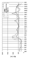
- FIG. 3 shows an example of load power measurement.
- the measured value (solid line) of in-house power consumption on April 1, 2014, the average power value in April of the previous year (dotted line), and the moving average value for two weeks before April 1 (dashed line) are shown. Is.
- the moving average value is closer to the actually measured value than the April average value of the previous year.
- the prediction accuracy of the residential load power can be improved.
- such home load power prediction can be regarded as a time average of power consumption in the home, and can be approximated to human behavior. Predictive accuracy is high when there is no continuous vacation or sudden weather change.
- the amount of photovoltaic power generation can obtain a predicted amount with a relatively high accuracy based on the weather forecast of the previous day, it can be approximated to a prediction.
- the storage battery capacity, the in-home load power amount, the PV power generation amount, and the grid power purchase amount can be managed easily and with a small control device. Even during sudden fluctuations, the output can be corrected according to the SOC.
- Example of concrete control In sunny weather and cloudy weather, for example, PV generated power was sold to commercial power from 11:00 to 13:00, and the load power in the house was calculated using a moving average equation while the PV power generation capacity was accumulated in the storage battery to the maximum during other times. By operating and supplying based on the predicted amount, the power consumption in the home can be predicted almost accurately, and charging to the storage battery and the SOC value of the battery can be accurately obtained. With the combined prediction of storage battery, PV power generation, and residential load, it is possible to set a power selling time zone for system power in the daytime time zone and minimize the amount of power purchased.
- Contract power is set for payment of power charges with electric power companies.
- One method of determining contract power is to use the maximum demand power in the past year including the current month as the contract power. Another way to determine contract power is by consultation. Also in this case, when the maximum demand power becomes higher than the preset contract power, the contract power for the next time (the next year, etc.) may increase in addition to the need to pay an excess fee.
- Step ST0 The time is confirmed.
- Step ST1 The maximum PV power generation amount is confirmed.
- Step ST2 The home load prediction value Pf is confirmed with reference to the load power prediction data.
- Step ST3 The actual home load value Pr, which is the current load power value in the home, is confirmed. The processing so far is the same as steps ST0 to ST3 in the embodiment.
- Step ST21 It is determined whether (Pf> Pcont) or (Pr> Pcont).
- Step ST23 It is determined whether (SOC ⁇ 10%).
- the assumed SOC is 30% to 50%.
- the threshold value of the determination process may be 30%.
- Step ST24 When the result of step ST23 is affirmative, control is performed such that discharging of the storage battery has the highest priority. Then, the process returns to step ST0.
- Step ST25 If not (SOC ⁇ 10%), the power purchase amount is increased. Then, the process returns to step ST0.
- Step ST26 If the determination result of step ST21 is negative, that is, if the estimated accumulated power for 30 minutes is predicted not to exceed the contracted power value, the storage battery output value is set to the system limit value (usually 0.5 to 1 ItA). To be maintained. Then, the process returns to step ST4 (see FIG. 2). Processes other than those described above are the same as in the embodiment.
- the battery module upper limit value can be output in a short time by setting the emergency output function. Since the remaining capacity is released, the temperature rise of the storage battery system can be suppressed to about 1 to 2 ° C. over the normal operation, so that it can be operated within a range that does not affect the system life.
- the house 101 is provided with a power generation device 104, a power consumption device 105, a power storage device 103, a control device 110 that controls each device, a smart meter 107, and a sensor 111 that acquires various types of information.
- Each device is connected by a power network 109 and an information network 112.
- a solar cell, a fuel cell, or the like is used as the power generation device 104, and the generated power is supplied to the power consumption device 105 and / or the power storage device 103.
- the power consuming device 105 is a refrigerator 105a, an air conditioner 105b, a television receiver 105c, a bath 105d, and the like.
- the electric power consumption device 105 includes an electric vehicle 106.
- the electric vehicle 106 is an electric vehicle 106a, a hybrid car 106b, and an electric motorcycle 106c.
- the power storage device 103 is composed of a secondary battery or a capacitor.
- a lithium ion battery is used.
- the lithium ion battery may be a stationary type or used in the electric vehicle 106.
- the smart meter 107 has a function of measuring the usage amount of commercial power and transmitting the measured usage amount to an electric power company.
- the power network 109 may be any one or a combination of DC power supply, AC power supply, and non-contact power supply. The present technology can be applied to a power supply device including the power storage device 103 and the control device 110.
- the various sensors 111 are, for example, human sensors, illuminance sensors, object detection sensors, power consumption sensors, vibration sensors, contact sensors, temperature sensors, infrared sensors, and the like. Information acquired by the various sensors 111 is transmitted to the control device 110. Based on the information from the sensor 111, the weather condition, the human condition, etc. can be grasped, and the power consumption device 105 can be automatically controlled to minimize the energy consumption. Furthermore, the control device 110 can transmit information regarding the house 101 to an external power company or the like via the Internet.
- the power hub 108 performs processing such as branching of power lines and DC / AC conversion.
- the communication method of the information network 112 connected to the control device 110 includes a method using a communication interface such as UART (Universal Asynchronous Receiver-Transmitter), Bluetooth (registered trademark), ZigBee, Wi-Fi.
- a communication interface such as UART (Universal Asynchronous Receiver-Transmitter), Bluetooth (registered trademark), ZigBee, Wi-Fi.
- the Bluetooth (registered trademark) system is applied to multimedia communication and can perform one-to-many connection communication.
- ZigBee uses the physical layer of IEEE (Institute of Electrical and Electronics Electronics) (802.15.4). IEEE 802.15.4 is the name of a short-range wireless network standard called PAN (Personal Area Network) or W (Wireless) PAN.
- the control device 110 is connected to an external server 113.
- the server 113 may be managed by any one of the house 101, the power company, and the service provider.
- the information transmitted and received by the server 113 is, for example, information related to power consumption information, life pattern information, power charges, weather information, natural disaster information, and power transactions. These pieces of information may be transmitted / received from a power consuming device (for example, a television receiver) in the home, or may be transmitted / received from a device outside the home (for example, a mobile phone). Such information may be displayed on a device having a display function, for example, a television receiver, a mobile phone, a PDA (Personal Digital Assistant) or the like.
- the control device 110 that controls each unit includes a CPU (Central Processing Unit), a RAM (Random Access Memory), a ROM (Read Only Memory), and the like, and is stored in the power storage device 103 in this example.
- the control device 110 is connected to the power storage device 103, the home power generation device 104, the power consumption device 105, the various sensors 111, the server 113 and the information network 112, and adjusts, for example, the amount of commercial power used and the amount of power generation. have. In addition, you may provide the function etc. which carry out an electric power transaction in an electric power market.
- electric power is generated not only from the centralized power system 102 such as the thermal power generation 102a, the nuclear power generation 102b, and the hydroelectric power generation 102c but also from the home power generation device 104 (solar power generation, wind power generation) to the power storage device 103.
- the home power generation device 104 solar power generation, wind power generation
- the electric power obtained by solar power generation is stored in the power storage device 103, and midnight power with a low charge is stored in the power storage device 103 at night, and the power stored by the power storage device 103 is discharged during a high daytime charge. You can also use it.
- control device 110 is stored in the power storage device 103 .
- control device 110 may be stored in the smart meter 107 or may be configured independently.
- the power storage system 100 may be used for a plurality of homes in an apartment house, or may be used for a plurality of detached houses.
- FIG. 6 schematically shows an example of the configuration of a hybrid vehicle that employs a series hybrid system to which the present technology is applied.
- the series hybrid system is a vehicle that runs on a power driving force conversion device using electric power generated by a generator driven by an engine or electric power once stored in a battery.
- the hybrid vehicle 200 includes an engine 201, a generator 202, a power driving force conversion device 203, driving wheels 204a, driving wheels 204b, wheels 205a, wheels 205b, a battery 208, a vehicle control device 209, various sensors 210, and a charging port 211.
- a battery 208 is used as the battery module in the power supply device of the present technology described above. That is, the battery 208 of the electric vehicle is used as a power supply device for homes and the like.
- Hybrid vehicle 200 travels using electric power / driving force conversion device 203 as a power source.
- An example of the power driving force conversion device 203 is a motor.
- the electric power / driving force converter 203 is operated by the electric power of the battery 208, and the rotational force of the electric power / driving force converter 203 is transmitted to the driving wheels 204a and 204b.
- DC-AC DC-AC
- AC-DC conversion AC-DC conversion
- the power driving force converter 203 can be applied to either an AC motor or a DC motor.
- the various sensors 210 control the engine speed via the vehicle control device 209 and control the opening (throttle opening) of a throttle valve (not shown).
- the various sensors 210 include a speed sensor, an acceleration sensor, an engine speed sensor, and the like.
- the rotational force of the engine 201 is transmitted to the generator 202, and the electric power generated by the generator 202 by the rotational force can be stored in the battery 208.
- the resistance force at the time of deceleration is applied as a rotational force to the power driving force conversion device 203, and the regenerative power generated by the power driving force conversion device 203 by this rotational force is applied to the battery 208. Accumulated.
- the battery 208 is connected to a power source outside the hybrid vehicle, so that it can receive power from the external power source using the charging port 211 as an input port and store the received power.
- an information processing device that performs information processing related to vehicle control based on information related to the secondary battery may be provided.
- an information processing apparatus for example, there is an information processing apparatus that displays a remaining battery capacity based on information on the remaining battery capacity.
- the present technology is also effective for a parallel hybrid vehicle in which the engine and motor outputs are both driving sources, and the system is switched between the three modes of driving with only the engine, driving with the motor, and engine and motor. Applicable. Furthermore, the present technology can be effectively applied to a so-called electric vehicle that travels only by a drive motor without using an engine.
- this technique can also take the following structures.
- the charging of the storage battery unit is controlled based on the load power prediction obtained by moving and averaging the power used and the power generation amount of the solar power generation device, and the power generation amount of the solar power generation device is used as the SOC of the storage battery unit.
- a control device that performs control to switch output to the storage battery unit or commercial power.
- the said control apparatus is an electric power supply apparatus as described in (1) (2) (3) or (4) which controls so that the full charge of the said storage battery part becomes after evening.
- the control device compares the predicted load power value or the load power with a threshold value slightly smaller than the contract power, the predicted load power value or the load power exceeds the threshold value, and the remaining capacity of the storage battery unit is a predetermined amount. In the above case, the power supply device according to (1), wherein the output of the storage battery unit is controlled to be changed to a maximum output value.
- the charging of the storage battery unit is controlled based on the load power prediction obtained by moving average the power used and the power generation amount of the solar power generation device, and the power generation amount of the solar power generation device is based on the SOC of the storage battery unit
- the control apparatus which performs control which switches an output to the said storage battery part or commercial system electric power.
Landscapes
- Engineering & Computer Science (AREA)
- Power Engineering (AREA)
- Charge And Discharge Circuits For Batteries Or The Like (AREA)
- Supply And Distribution Of Alternating Current (AREA)
- Stand-By Power Supply Arrangements (AREA)
Abstract
太陽光発電装置と、蓄電池部と、太陽光発電装置の電力を前記蓄電池部へ供給する充電器と、蓄電池部の放電出力を交流電力へ変換する直流-交流電力変換回路部と、使用電力を移動平均することによって求められる負荷電力予測と太陽光発電装置の発電量に基づいて蓄電池部の充電を制御し、かつ太陽光発電装置の発電量を蓄電池部のSOCに基づいて、蓄電池部もしくは商用系統電力へ出力を切り替える制御を行う制御装置とを備える電力供給装置である。
Description
本技術は、外部電力系統と太陽電池の出力電力と蓄電装置の出力電力とを利用して電力供給を行うようにした電力供給装置及び制御装置に関する。
最近では、より大きな容量の家庭用の蓄電装置が実用化されている。家庭用の蓄電装置を活用することによって、停電時の電力供給を確保し、外部電力系統の電力需要量、電力使用量を削減することが可能である。例えば外部電力系統からの交流電力の供給を減少させ、不足する電力を蓄電装置によって補うことが考えられる。さらに、家庭内の電力需要が増加し、電力供給事業者との間の契約している契約電力を超え、ブレーカが作動して電力が遮断されるおそれが生じる。そのような場合に、蓄電装置の出力電力を供給することによって、契約電力を超えるような事態を回避することができる。さらに、太陽電池出力と蓄電装置の出力電力とを混合して出力することが考えられている。
例えば特許文献1には、発電部によって発電された電力を蓄電池制御部によって蓄電池に貯えるようにし、残容量値と、推定された負荷使用電力パターンと、発電予測パターンとに基づいて、充電電流値を制限する時間帯を指定し、制限時間帯における充電電流値を演算することが記載されている。蓄電池が過度の充電電流値によって充電することを防止するようになされている。
特許文献2には、複数のクライアント装置と通信可能なサーバ装置とを具備する。サーバ装置は取得部、予測部、計算部、制御部を備えるエネルギー管理システムであって、予測されたエネルギー需要量に基づいて需要者におけるエネルギー収支を最適化可能な電気機器の稼動スケジュールを計算する。制御部は計算された稼動スケジュールに基づいて電気機器を制御するための制御情報をクライアント装置に送信するようにしたエネルギー管理システムが記載されている。
蓄電池から負荷への出力電力量を一定で行えることが蓄電池使用では望ましい。なぜなら、蓄電池出力の急変動により電池劣化が引き起こされるからである。例えば出力値不定な状態として突然最大出力値の直後に0W出力となるような負荷が蓄電池に掛かった場合、蓄電池では大電流の出力により発熱が急に起こり、電池劣化が進むことになる。電極内でリチウムの均衡・平衡な状態に達するまで数十分の時間が掛かかるため、急速な充放電は電池の電極内でリチウムイオンの不均衡な状態を発生させ、このままで次の充放電が行われると更に不均衡が加速される。
電力予測を行うことができれば、蓄電池の出力を一定値で行うことができ、予想から外れている電力量のみ出力量の補正をして、蓄電池に掛かる変動量を少なくでき、電池の劣化が少なくなるように運転することができる。蓄電池の容量急劣化を防止でき、長期間運用での信頼性を向上することができる。
上述した特許文献1及び特許文献2に記載のものでは、電力予測を高精度に行うことについての記載がない。したがって、急激な負荷の変化によって蓄電池部が劣化するおそれがあった。さらに、蓄電池部のSOC(State Of Charge)を適正な範囲に保ちつつ、蓄電池部の出力電力を家庭内で使用する電力へ供給して買電量を低減し、電気料金削減を行うようにする点についても特許文献1及び特許文献2には、開示されていない。
したがって、本技術の目的は、電力需要の精度を高くすることによって、蓄電池部の出力の急激な変動を防止して蓄電池部の劣化を防止でき、さらに、蓄電池部のSOCを適正な範囲に保ちつつ蓄電池部の出力電力を供給することができる電力供給装置及び制御装置を提供することにある。
上述した課題を解決するために、本技術は、太陽光発電装置と、
蓄電池部と、
太陽光発電装置の電力を蓄電池部へ供給する充電器と、
蓄電池部の放電出力を交流電力へ変換する直流-交流電力変換回路部と、
使用電力を移動平均することによって求められる負荷電力予測と太陽光発電装置の発電量に基づいて蓄電池部の充電を制御し、かつ太陽光発電装置の発電量を蓄電池部のSOCに基づいて、蓄電池部もしくは商用系統電力へ出力を切り替える制御を行う制御装置とを備える電力供給装置である。
さらに、本技術は、使用電力を移動平均することによって求められる負荷電力予測と太陽光発電装置の発電量に基づいて蓄電池部の充電を制御し、かつ太陽光発電装置の発電量を蓄電池部のSOCに基づいて、蓄電池部もしくは商用系統電力へ出力を切り替える制御を行う制御装置である。
少なくとも一つの実施形態によれば、本技術は、負荷電力予測によって蓄電池部の出力を制御するので、蓄電池部の出力の急激な変動を防止して蓄電池部の劣化を防止することができる。また、本技術では外部電力系統と蓄電装置の出力電力とを混合することによって、構内(屋内)負荷の急激な変動を吸収して外部電力系統の使用をほぼ一定とできる。その結果、契約電力を低くすることが可能となり、電力料金の増大を抑制できる。なお、ここに記載された効果は必ずしも限定されるものではなく、本技術中に記載されたいずれかの効果であっても良い。
以下、本技術の実施の形態について説明する。なお、以下に説明する実施の形態は、本技術の好適な具体例であり、技術的に好ましい種々の限定が付されているが、本技術の範囲は、以下の説明において、特に本技術を限定する旨の記載がない限り、これらの実施の形態に限定されないものとする。
本技術の説明は、以下の順序にしたがってなされる。
<1.一実施の形態>
<2.他の実施の形態>
<3.応用例>
<4.変形例>
本技術の説明は、以下の順序にしたがってなされる。
<1.一実施の形態>
<2.他の実施の形態>
<3.応用例>
<4.変形例>
<1.一実施の形態>
「電力供給装置の構成」
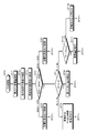
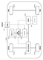
図1を参照して本技術による電力供給装置について説明する。電力供給者の発電所にて発電した電力が図示しない送電網、配電網を介して家庭の電力量計に供給され、電力量計から図1における外部電力系統(商用電力)入力端子1に交流電力が供給される。なお、家庭における電力制御について説明するが、家庭に限らず、複数の家(コミュニティー)、ビル、工場等の電力供給の面で区画されたエリアであれば、本技術を適用することができる。
「電力供給装置の構成」
図1を参照して本技術による電力供給装置について説明する。電力供給者の発電所にて発電した電力が図示しない送電網、配電網を介して家庭の電力量計に供給され、電力量計から図1における外部電力系統(商用電力)入力端子1に交流電力が供給される。なお、家庭における電力制御について説明するが、家庭に限らず、複数の家(コミュニティー)、ビル、工場等の電力供給の面で区画されたエリアであれば、本技術を適用することができる。
一般的に、屋外の配電線から引き込み線を通じて建物内に電力線が導入され、電力線が電力メータに接続される。電力メータの出力側に分電盤が接続される。分電盤からの屋内配線に対して電気機器が接続される。例えば本技術による電力供給装置は、電力メータと分電盤との間に設けられる。一般的な住宅の場合、単相3線式であり、中央の中性線と2本の電圧線の計3本の電線を使用する。中性線と一方の電圧線を利用して100Vの電圧を利用でき、2つの電圧線を利用して200Vの電圧を利用できる。なお、本技術は、2線式に対しても適用できる。
入力端子1からの商用電力が供給され、スイッチSW1を介して商用電力が破線で囲んで示すUPS(Uninterruptible Power Supply:無停電電源装置)部8に入力される。UPS部8は、AC(交流)-DC(直流)コンバータ3及びDC-ACインバータ4、スイッチSW2及びスイッチSW3を有する。商用電力P1がUPS部8に供給される。AC-DCコンバータ3は、商用電力から直流電力を形成する。AC-DCコンバータ3の出力直流電力がDC-ACインバータ4に供給される。DC-ACインバータ4は、商用電力と同様のレベル及び周波数の交流電力を形成する。DC-ACインバータ4の出力交流電力がスイッチSW3を介して交流電力供給端子2に取り出される。スイッチSW1,SW2,SW3は、コントロール信号によってオン/オフが制御されるものである。
商用電力がスイッチSW1及びSW2を介して交流電力供給端子2に供給される。スイッチSW1が分電盤のブレーカの場合もある。交流電力供給端子2に対して屋内電力網が接続される。例えば図示しないが、交流電力が配電盤(分電盤を含む)に供給され、配電盤から導出された電力線及びコンセントを通じて電子機器群の各電子機器に対して電力が供給される。電子機器群の例は、空調装置、冷蔵庫、照明器具、洗濯機、テレビジョン受信機等である。屋内電力網の機器が使用する電力が負荷電力である。
AC/DCコンバータ3の出力及びDC-ACインバータ4の入力の接続点と蓄電池部、例えば電池モジュール5との間にDC-DCコンバータ9が接続される。DC-DCコンバータ9は、両方向性のものである。すなわち、AC/DCコンバータ3によって商用電力から形成された直流電力P2がDC-DCコンバータ9を介して電池モジュール5に対して充電電力として供給される。一方、電池モジュール5の放電電力P3がDC-DCコンバータ9に供給され、DC-DCコンバータ9の出力がDC-ACインバータ4に供給され、DC-ACインバータ4からスイッチSW3を介して交流電力供給端子2に交流電力が取り出される。これらのAC/DCコンバータ3、DC-ACインバータ4、DC-DCコンバータ9、スイッチSW2及びスイッチSW3の部分がUPS部8を構成している。
電池モジュール5として、例えば8本の円筒状リチウムイオン二次電池を並列接続して電池ブロックを構成し、16個の電池ブロックを直列接続して共通のケース内に収納した構成を使用することができる。電池モジュール5の他の例は、電気二重層、大容量キャパシタ等である。なお、電池モジュール5として、定置型に限らず、電動車両で使用されるものでも良い。
屋根、屋外等に太陽電池モジュール10が設置されている。太陽電池モジュール10は、複数の太陽電池を接続してパネル状としたものである。ソーラーパネルとも称される。通常、複数枚の太陽電池モジュール10が並べて設置され、太陽電池アレイが構成される。例えば太陽電池モジュール10は、2kW~4kWの発電が可能とされている。
太陽電池モジュール10の出力電力P4がDC-DCコンバータ11及びパワーコンディショナ12を介して外部電力系統の電力供給ラインに供給される。パワーコンディショナ12は、DC-DCコンバータ部と、DC-ACインバータ部とからなる電力変換部を有する。DC-DCコンバータ部は、入力直流電圧を昇圧し、DC-ACインバータ部に供給する。DC-ACインバータ部は、DC-DCコンバータ部からの直流電圧を交流電力に変換する。さらに、パワーコンディショナ12は、最大電力点追従制御(Maximum Power Point Tracking:MPPT)と称される制御を行う。この制御は、太陽電池モジュール10の発電電力の変動に追従して、常に最大の電力点を追いかける方式である。
パワーコンディショナ12の出力が外部電力系統の電力供給ラインに接続されているので、太陽電池モジュール10の発電電力が宅内の消費電力を上回る場合には余剰電力が売電される。余剰電力が売電されることを逆潮流と称する。図示しないが、逆潮流の電力を測定するメータが接続されている。なお、UPS部8において、太陽電池モジュール10の発電電力と電池モジュール5の出力電力とが混合して宅内負荷に供給される。
さらに、太陽電池モジュール10の出力電力がPV充電器13に供給される。PV充電器13は、太陽電池モジュール10の出力電力が供給されるDC-DCコンバータ14と充電制御部15とを有する。充電制御部15の出力電力P5がUPS部8に供給され、負荷電力P8として使用される。これと共に、充電制御部15の出力電力P6が電池モジュール5に供給される。電池モジュール5には、上述したUPS部8のDC-DCコンバータ9が接続されており、電池モジュール5は、充電制御部15を介された太陽電池モジュール10の出力と、UPS部8からの商用電力P7との何れか一方によって充電される。
商用電力で電池モジュール5を充電する場合は、定格電流が充電電流とされる。太陽電池モジュール10からの充電時に、充電制御部15は、電池モジュール5のSOCに応じた充電電流を形成する。例えばSOCが50%以下では、1Cの充電電流を形成し、SOCが80%~90%では、0.5Cの充電電流を形成し、SOCが90%を超える場合には、0.2Cの充電電流を形成する。
例えば、電池モジュール5は、リチウムイオン二次電池からなり、充電時には、CC(定電流)/CV(定電圧)でもって充電される。すなわち、最初は、所定の電流によって電池モジュールが充電され、所定の電圧まで充電されると、定電圧充電に切り替えられる。PV充電器13による充電制御は、充電電流の値を制御する処理を行う。
電池モジュール5に対する充電制御は、BMU(Battery Management Unit)6と通信しているEMU(Energy Management Unit)7によってなされる。BMU6は、電池モジュール5の状態(残容量、電池電圧、電池温度等)を監視し、適切な充放電動作が行われるようになされる。BMU6が取得した電池モジュール5の残容量の情報は、EMU7に伝送され、EMU7の動作モードの切り替えに使用される。EMU7がUPS部8のスイッチを制御し、AC-DCコンバータ3及びDC-ACインバータ4を制御する。EMU7は、太陽電池モジュール10の出力電力をモニタしている。太陽電池モジュール10の出力電力が所定以上であれば、PV充電器13の出力によって電池モジュール5を充電する。したがって、昼間のような場合には、太陽電池モジュール10によって電池モジュール5が充電される。なお、本例では、BMU6及びEMU7が別々の構成として記載されているが、これらを一つのマイクロコンピュータ等で実現し、一体化しても良い。
EMU7に接続されたメモリ16には、予め取得されている当該屋内における負荷電力予測データが記憶されている。負荷電力すなわち、屋内における消費電力の合計電力の予測データがEMU7に供給され、EMU7がシステム全体を制御する。一例として、負荷電力予測データは、1日(24時間)を30分単位で区切り、各時刻における負荷電力予測データを示すものである。
「電力供給装置の制御動作」
上述の一実施の形態は、太陽電池モジュール10の発電量、電池モジュール5の蓄電量、負荷電力予測データに応じて電力を制御する。さらに、それぞれの電力を必要に応じて混合出力する。本技術の一実施の形態における制御動作の一例を下記の表1に示す。
上述の一実施の形態は、太陽電池モジュール10の発電量、電池モジュール5の蓄電量、負荷電力予測データに応じて電力を制御する。さらに、それぞれの電力を必要に応じて混合出力する。本技術の一実施の形態における制御動作の一例を下記の表1に示す。

EMU7は、この表1にしたがって図2に示すフローチャートで示すように、システムを制御する。なお、表1及び図2では省略しているが、スイッチSW1及びSW2がオンとされる場合には、入力商用電力がそのまま交流電力供給端子2に取り出される。このバイパス動作は、何らかの異常が検出されると行われる。電池モジュールの交換、ファンの点検等の保守のための保守バイパスモードも同様に可能とされている。なお、表1及び図2並びに以下の説明において、電池モジュール5を蓄電池と適宜表記し、太陽電池モジュール10をPVと適宜表記する。
ステップST0:時刻が確認される。
ステップST1:最大PV発電量が確認される。
ステップST2:負荷電力予測データを参照して宅内負荷予測値Pfが確認される。
ステップST3:現在の家庭内の負荷電力の値である実動宅内負荷値Prが確認される。
ステップST4:蓄電池のSOCが判定される。すなわち、SOCが小さい場合例えば(SOC<20%)の場合、SOCが適正な範囲である場合例えば(20%<SOC<80%)の場合、並びにSOCが大きい場合例えば(SOC>80%)の場合の何れであるかが判定される。
ステップST1:最大PV発電量が確認される。
ステップST2:負荷電力予測データを参照して宅内負荷予測値Pfが確認される。
ステップST3:現在の家庭内の負荷電力の値である実動宅内負荷値Prが確認される。
ステップST4:蓄電池のSOCが判定される。すなわち、SOCが小さい場合例えば(SOC<20%)の場合、SOCが適正な範囲である場合例えば(20%<SOC<80%)の場合、並びにSOCが大きい場合例えば(SOC>80%)の場合の何れであるかが判定される。
ステップST5:(SOC<20%)の場合には、蓄電池の充電を最優先とする制御がなされる。そして、ステップST0に戻って(ステップST1~ステップST4)の処理がなされる。
具体的には、表1の(SOC=0~20%)の項目で示すように、基本的に蓄電池は充電のみが可能とされている。表1において、出力/充電は、PV発電電力が電力供給ラインに出力されると共に、蓄電池の充電に使用されることを意味する。
具体的には、表1の(SOC=0~20%)の項目で示すように、基本的に蓄電池は充電のみが可能とされている。表1において、出力/充電は、PV発電電力が電力供給ラインに出力されると共に、蓄電池の充電に使用されることを意味する。
ステップST6:(SOC<80%)の場合には、蓄電池の放電を最優先とする制御がなされる。そして、ステップST0に戻って(ステップST1~ステップST4)の処理がなされる。
具体的には、表1の(SOC=80~100%)の項目で示すように、蓄電池からの放電を主として運転される。但し、例外として、夕方には蓄電池をSOC100%付近まで持ち上げる動作がなされる。これは 夜間に蓄電池の電力を活用して宅内負荷に電力を供給させる場合である。このときは、夕方PV発電が行われている場合にのみ蓄電池を充電するために、PV充電器13の出力を制限して、蓄電池をSOC100%付近まで充電させる動作がなされる。すなわち、充電電流を絞って蓄電池が満充電し易い条件を設定する。通常のMPPT動作では蓄電池充電がオン-オフ動作で2時間程度掛かってしまうことを避けるためである。さらに、PV発電量が負荷電力よりも少ない状態では蓄電池からの出力が負荷電力に供給される。
具体的には、表1の(SOC=80~100%)の項目で示すように、蓄電池からの放電を主として運転される。但し、例外として、夕方には蓄電池をSOC100%付近まで持ち上げる動作がなされる。これは 夜間に蓄電池の電力を活用して宅内負荷に電力を供給させる場合である。このときは、夕方PV発電が行われている場合にのみ蓄電池を充電するために、PV充電器13の出力を制限して、蓄電池をSOC100%付近まで充電させる動作がなされる。すなわち、充電電流を絞って蓄電池が満充電し易い条件を設定する。通常のMPPT動作では蓄電池充電がオン-オフ動作で2時間程度掛かってしまうことを避けるためである。さらに、PV発電量が負荷電力よりも少ない状態では蓄電池からの出力が負荷電力に供給される。
ステップST7:(20%<SOC<80%)の場合には、宅内負荷予測値Pfと実動宅内負荷値Prとがほぼ等しいかどうかが判定される。すなわち、実際の宅内消費電力が予測した値に近いかどうかが判定される。
ステップST8:PfとPrとがほぼ等しい場合には、表1に従って電力制御がなされる。そして、ステップST0に戻って(ステップST1~ステップST4)の処理がなされる。表1のSOCが(20%~80%)の欄に示すように、(最大PV発電量>負荷電力量)の場合には、負荷への給電がなされると共に、蓄電池が充電される。例えば晴天時になされる制御である。
ステップST8:PfとPrとがほぼ等しい場合には、表1に従って電力制御がなされる。そして、ステップST0に戻って(ステップST1~ステップST4)の処理がなされる。表1のSOCが(20%~80%)の欄に示すように、(最大PV発電量>負荷電力量)の場合には、負荷への給電がなされると共に、蓄電池が充電される。例えば晴天時になされる制御である。
また、(最大PV発電量≒負荷電力量)の場合には,負荷への給電と共に、蓄電池の充電又は放電を行う。例えば曇天時では、蓄電池へ充電と、蓄電池からの放電との切り替わりが頻繁に発生する。さらに、(最大PV発電量<負荷電力量)の場合には,蓄電池が充電動作から放電動作に切り替わる。例えば雨天の時では、PV発電不足となるために蓄電池が放電を行う。なお、蓄電池の放電(出力)は、SOCが20%までとされる。
ステップST9:ステップST7において、宅内負荷予測値Pfが実動宅内負荷値Prを大幅に上回ると判定された場合、すなわち、予測値を大きく外れて軽負荷となった場合には、系統電力の買電の休止と、PV出力制限と、蓄電池出力とがなされる。蓄電池のみで電力供給を行い、系統商用電力の買電を休止できる。
ステップST10:ステップST7において、宅内負荷予測値Pfより実動宅内負荷値Prが大幅に上回ると判定された場合、すなわち、予測値を大きく外れて重負荷となった場合には、実動宅内負荷値Prが蓄電池の最大出力Pmax を超えるかどうかが判定される。
ステップST11:ステップST10において、実動宅内負荷値Prが蓄電池の最大出力Pmax を超えると判定されると、系統商用電力の買電量を増加させて負荷に供給する。そして、ステップST0に戻って(ステップST1~ステップST4)の処理がなされる。
ステップST12:ステップST10において、実動宅内負荷値Prが蓄電池の最大出力Pmax を超えないと判定されると、蓄電池の出力電力の割合を大きくする。そして、ステップST0に戻って(ステップST1~ステップST4)の処理がなされる。
ステップST11:ステップST10において、実動宅内負荷値Prが蓄電池の最大出力Pmax を超えると判定されると、系統商用電力の買電量を増加させて負荷に供給する。そして、ステップST0に戻って(ステップST1~ステップST4)の処理がなされる。
ステップST12:ステップST10において、実動宅内負荷値Prが蓄電池の最大出力Pmax を超えないと判定されると、蓄電池の出力電力の割合を大きくする。そして、ステップST0に戻って(ステップST1~ステップST4)の処理がなされる。
「負荷消費電力の予測」
電池モジュールは、SOCが(20%~80%)の範囲を最適に使用して家庭内で使用する電力へ供給して買電量を低減し、電気料金削減を行うことができる。SOCのこの範囲外は緊急用として使用する。蓄電池から負荷への出力電力量を一定で行えることが蓄電池使用では望ましい。なぜなら、蓄電池出力の急変動により電池劣化を引き起こすからである。例えば出力値不定な状態として突然最大出力値の直後に0W出力となるような負荷が蓄電池に加わることになった場合、蓄電池では大電流の出力により発熱が急に起こり、電池劣化が進むことになる。電極内でリチウムの均衡・平衡な状態に達するまで数十分の時間が掛かかるため、急速な充放電は電池の電極内でリチウムイオンの不均衡な状態を発生させ、このままで次の充放電が行われると更に不均衡が加速される。
電池モジュールは、SOCが(20%~80%)の範囲を最適に使用して家庭内で使用する電力へ供給して買電量を低減し、電気料金削減を行うことができる。SOCのこの範囲外は緊急用として使用する。蓄電池から負荷への出力電力量を一定で行えることが蓄電池使用では望ましい。なぜなら、蓄電池出力の急変動により電池劣化を引き起こすからである。例えば出力値不定な状態として突然最大出力値の直後に0W出力となるような負荷が蓄電池に加わることになった場合、蓄電池では大電流の出力により発熱が急に起こり、電池劣化が進むことになる。電極内でリチウムの均衡・平衡な状態に達するまで数十分の時間が掛かかるため、急速な充放電は電池の電極内でリチウムイオンの不均衡な状態を発生させ、このままで次の充放電が行われると更に不均衡が加速される。
本技術では、電力予測を行うことによって、蓄電池の出力を一定値とすることができ、予想から外れている電力量のみ出力量の補正をして、蓄電池に掛かる変動量を少なくでき、電池の劣化が少なくなるように運転することができる。蓄電池の容量急劣化を防止でき、長期間運用での信頼性を向上することができる。
上述した負荷電力予測データの作成について説明する。消費電力量の予測手法として、より精度を向上させるために移動平均を用いる。移動平均の主要なものは、単純移動平均と加重移動平均と指数移動平均の3種類がある。一例として消費電力量の予測手法としてデータの重み付けのない単純移動平均(Simple Moving Average:SMA)を使用する。
移動平均の期間は、例えば2週間(14日間)を使用する。次式は、ある時間帯(30分間)の直近14日間の積算電力の単純移動平均を示すものである。翌日の単純移動平均を求めるためには、最も古い積算電力を除けばよい。
SMA30=(PM+PM-1+------+PM-13)/14
SMA30:30分間の積算電力平均、単位:Wh
PM:前日のある時間帯の30分間の積算電力
PM-1:前々日のある時間帯の30分間の積算電力
PM-13:2週間前のある時間帯の30分間の積算電力
SMA30:30分間の積算電力平均、単位:Wh
PM:前日のある時間帯の30分間の積算電力
PM-1:前々日のある時間帯の30分間の積算電力
PM-13:2週間前のある時間帯の30分間の積算電力
図3は、負荷電力の測定例を示している。例えば2014年4月1日の宅内消費電力の実測値(実線)と、前年度4月の電力平均値(点線)と、4月1日の前の2週間の移動平均値(破線)を示すものである。図3のグラフに示すように、前年度4月平均値に比較して移動平均値のほうが、実測値に近い値を示している。このように、宅内負荷電力の予測精度を向上することができる。すなわち、かかる宅内負荷電力予測は家庭内での電力消費量の時間平均とみることができ、ほぼ人間行動に近似できる。連続休暇や気象急変が無い場合における予測確度が高い。さらに、太陽光発電量は前日の天気予報に基づき確度の比較的高い予想量を得ることができるので、ほぼ予測に近似できる。
上述した本技術は、蓄電池容量と、宅内負荷電力量と、PV発電量と、系統電力買電量とを簡易でしかも、小さな制御装置で管理することができる。急な変動時においても、SOCに応じて出力の修正ができる。
「具体的制御の例」
晴天・曇天では、例えば11時~13時にPV発電電力を商用電力へ売電し、これ以外の時間帯でPV発電容量を蓄電池に最大限蓄積させながら、宅内負荷電力を移動平均式で求めた予測量に基づいて運転供給させることで、宅内の消費電力をほぼ正確に予測でき、蓄電池へ充電や電池のSOC値を正確に求めることができる。蓄電池とPV発電と宅内負荷との合算予測で、昼間時間帯に系統電力への売電時間帯を設定し、買電量を最小化できる。
晴天・曇天では、例えば11時~13時にPV発電電力を商用電力へ売電し、これ以外の時間帯でPV発電容量を蓄電池に最大限蓄積させながら、宅内負荷電力を移動平均式で求めた予測量に基づいて運転供給させることで、宅内の消費電力をほぼ正確に予測でき、蓄電池へ充電や電池のSOC値を正確に求めることができる。蓄電池とPV発電と宅内負荷との合算予測で、昼間時間帯に系統電力への売電時間帯を設定し、買電量を最小化できる。
<2.他の実施の形態>
本技術の他の実施の形態について説明する。電力会社との電力料金の支払いに関して、契約電力を定めている。契約電力の定め方の一つとして、当月を含めた過去1年の最大需要電力を契約電力とするものがある。契約電力を決定する他の方法としては協議による方法がある。この場合も、最大需要電力が予め設定した契約電力より高くなると、超過料金を支払う必要があるのに加えて次回(翌年等)の契約電力が高くなることがある。
本技術の他の実施の形態について説明する。電力会社との電力料金の支払いに関して、契約電力を定めている。契約電力の定め方の一つとして、当月を含めた過去1年の最大需要電力を契約電力とするものがある。契約電力を決定する他の方法としては協議による方法がある。この場合も、最大需要電力が予め設定した契約電力より高くなると、超過料金を支払う必要があるのに加えて次回(翌年等)の契約電力が高くなることがある。
契約電力が上昇すると電気料金が高くなるので、既に決めている契約電力を最大需要電力が上回ることがないように注意する必要がある。蓄電システムの運転法では、負荷電力急増時には商用電力からの買電量を増やして電力供給を行っていた。しかしながら、契約電力の上限値近傍で行うと、契約電力を最大需要電力が上回ることが生じ、次回の契約電力の増大となってしまい、本来蓄電池システム導入による電力平準化の削減効果が得られないことになる。
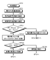
そこで、他の実施の形態では、契約電力上限値近傍で負荷電力の急増が起こった際には、蓄電池からの供給電力量を電池モジュールの上限出力で供給できるようにするものである。図4を参照して他の実施の形態について説明する。他の実施の形態は、上述した一実施の形態と組み合わされる例であり、図2のフローチャートのステップST3とステップST4との間に、図4のフローチャートの処理が挿入される。
ステップST0:時刻が確認される。
ステップST1:最大PV発電量が確認される。
ステップST2:負荷電力予測データを参照して宅内負荷予測値Pfが確認される。
ステップST3:現在の家庭内の負荷電力の値である実動宅内負荷値Prが確認される。
ここまでの処理は一実施の形態におけるステップST0~ST3と同様である。
ステップST1:最大PV発電量が確認される。
ステップST2:負荷電力予測データを参照して宅内負荷予測値Pfが確認される。
ステップST3:現在の家庭内の負荷電力の値である実動宅内負荷値Prが確認される。
ここまでの処理は一実施の形態におけるステップST0~ST3と同様である。
ステップST21:(Pf>Pcont)又は(Pr>Pcont)か、どうかが判定される。Pcontは、契約電力の上限値よりやや低い電力値である。例えば(Pcont=契約電力の上限値-契約電力の5%)と設定される。
ステップST22:ステップST21の判定結果が肯定の場合に、電池最大出力値をより大きな値に変更する。すなわち、通常の電力平準化運転中でも、30分間積算電力予想量が契約電力値を超えると予測された場合、緊急時電池出力の指令が出され、蓄電池出力値がシステム制限値(通常0.5~1ItA)を解除し、電池モジュール最大出力(2~3ItA)での出力値に変更される。
ステップST22:ステップST21の判定結果が肯定の場合に、電池最大出力値をより大きな値に変更する。すなわち、通常の電力平準化運転中でも、30分間積算電力予想量が契約電力値を超えると予測された場合、緊急時電池出力の指令が出され、蓄電池出力値がシステム制限値(通常0.5~1ItA)を解除し、電池モジュール最大出力(2~3ItA)での出力値に変更される。
ステップST23:(SOC<10%)か、どうかが判定される。想定するSOCは30%~50%である。判定処理のしきい値を例えば30%としても良い。
ステップST24:ステップST23の結果が肯定の場合には、蓄電池の放電を最優先とする制御がなされる。そして、処理がステップST0に戻る。
ステップST25:(SOC<10%)でない場合には、買電量を増大する。そして、処理がステップST0に戻る。
ステップST24:ステップST23の結果が肯定の場合には、蓄電池の放電を最優先とする制御がなされる。そして、処理がステップST0に戻る。
ステップST25:(SOC<10%)でない場合には、買電量を増大する。そして、処理がステップST0に戻る。
ステップST26:ステップST21の判定結果が否定の場合、すなわち、30分間積算電力予想量が契約電力値を超えないと予測される場合、蓄電池出力値がシステム制限値(通常0.5~1ItA)を維持するようになされる。そして、処理がステップST4(図2参照)に戻る。上述した以外の処理は、一実施の形態と同様である。
従来では、蓄電システムの設定上限値を超えた出力電力量を実施することは想定しておらず、制御装置にも設定されてこなかった。上述した本技術の他の実施の形態では、緊急出力機能を設定することで、短時間での電池モジュール上限値出力が可能とできる。残存容量を放出するので、蓄電池システムの温度上昇は、通常運転に対して1~2℃程度の上昇に抑えることができるので、システム寿命には影響を与えない範囲で運用できる。特に事業所や工場では、契約電力量を守ることで電力会社からのペナルティーを課されずに電力供給を受けることができる。これによって 蓄電システム導入による電力平準化と料金メリットの両方を受けることができる。
<3.応用例>
「応用例としての住宅における蓄電システム」
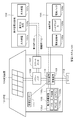
本技術を住宅用の蓄電システムに適用した例について、図5を参照して説明する。例えば住宅101用の蓄電システム100においては、火力発電102a、原子力発電102b、水力発電102c等の集中型電力系統102から電力網109、情報網112、スマートメータ107、パワーハブ108等を介し、電力が蓄電装置103に供給される。これと共に、家庭内発電装置104等の独立電源から電力が蓄電装置103に供給される。蓄電装置103に供給された電力が蓄電される。蓄電装置103を使用して、住宅101で使用する電力が給電される。住宅101に限らずビルに関しても同様の蓄電システムを使用できる。
「応用例としての住宅における蓄電システム」
本技術を住宅用の蓄電システムに適用した例について、図5を参照して説明する。例えば住宅101用の蓄電システム100においては、火力発電102a、原子力発電102b、水力発電102c等の集中型電力系統102から電力網109、情報網112、スマートメータ107、パワーハブ108等を介し、電力が蓄電装置103に供給される。これと共に、家庭内発電装置104等の独立電源から電力が蓄電装置103に供給される。蓄電装置103に供給された電力が蓄電される。蓄電装置103を使用して、住宅101で使用する電力が給電される。住宅101に限らずビルに関しても同様の蓄電システムを使用できる。
住宅101には、発電装置104、電力消費装置105、蓄電装置103、各装置を制御する制御装置110、スマートメータ107、各種情報を取得するセンサ111が設けられている。各装置は、電力網109及び情報網112によって接続されている。発電装置104として、太陽電池、燃料電池等が利用され、発電した電力が電力消費装置105及び/又は蓄電装置103に供給される。電力消費装置105は、冷蔵庫105a、空調装置105b、テレビジョン受信機105c、風呂105d等である。さらに、電力消費装置105には、電動車両106が含まれる。電動車両106は、電気自動車106a、ハイブリッドカー106b、電気バイク106cである。
蓄電装置103は、二次電池又はキャパシタから構成されている。例えば、リチウムイオン電池によって構成されている。リチウムイオン電池は、定置型であっても、電動車両106で使用されるものでも良い。スマートメータ107は、商用電力の使用量を測定し、測定された使用量を、電力会社に送信する機能を備えている。電力網109は、直流給電、交流給電、非接触給電の何れか一つ又は複数を組み合わせても良い。蓄電装置103及び制御装置110からなる電力供給装置に対して本技術を適用できる。
各種のセンサ111は、例えば人感センサ、照度センサ、物体検知センサ、消費電力センサ、振動センサ、接触センサ、温度センサ、赤外線センサ等である。各種センサ111により取得された情報は、制御装置110に送信される。センサ111からの情報によって、気象の状態、人の状態等が把握されて電力消費装置105を自動的に制御してエネルギー消費を最小とすることができる。さらに、制御装置110は、住宅101に関する情報をインターネットを介して外部の電力会社等に送信することができる。
パワーハブ108によって、電力線の分岐、直流交流変換等の処理がなされる。制御装置110と接続される情報網112の通信方式としては、UART(Universal Asynchronous Receiver-Transmitter:非同期シリアル通信用送受信回路)等の通信インターフェースを使う方法、Bluetooth(登録商標)、ZigBee、Wi-Fi等の無線通信規格によるセンサネットワークを利用する方法がある。Bluetooth(登録商標)方式は、マルチメディア通信に適用され、一対多接続の通信を行うことができる。ZigBeeは、IEEE(Institute of Electrical and Electronics Engineers)802.15.4の物理層を使用するものである。IEEE802.15.4は、PAN(Personal Area Network)又はW(Wireless)PANと呼ばれる短距離無線ネットワーク規格の名称である。
制御装置110は、外部のサーバ113と接続されている。このサーバ113は、住宅101、電力会社、サービスプロバイダーの何れかによって管理されていても良い。サーバ113が送受信する情報は、たとえば、消費電力情報、生活パターン情報、電力料金、天気情報、天災情報、電力取引に関する情報である。これらの情報は、家庭内の電力消費装置(たとえばテレビジョン受信機)から送受信しても良いが、家庭外の装置(たとえば、携帯電話機等)から送受信しても良い。これらの情報は、表示機能を持つ機器、たとえば、テレビジョン受信機、携帯電話機、PDA(Personal Digital Assistants)等に、表示されても良い。
各部を制御する制御装置110は、CPU(Central Processing Unit)、RAM(Random Access Memory)、ROM(Read Only Memory)等で構成され、この例では、蓄電装置103に格納されている。制御装置110は、蓄電装置103、家庭内発電装置104、電力消費装置105、各種センサ111、サーバ113と情報網112により接続され、例えば、商用電力の使用量と、発電量とを調整する機能を有している。なお、その他にも、電力市場で電力取引を行う機能等を備えていても良い。
以上のように、電力が火力発電102a、原子力発電102b、水力発電102c等の集中型電力系統102のみならず、家庭内発電装置104(太陽光発電、風力発電)の発電電力を蓄電装置103に蓄えることができる。したがって、家庭内発電装置104の発電電力が変動しても、外部に送出する電力量を一定にしたり、又は、必要なだけ放電するといった制御を行うことができる。例えば、太陽光発電で得られた電力を蓄電装置103に蓄えると共に、夜間は料金が安い深夜電力を蓄電装置103に蓄え、昼間の料金が高い時間帯に蓄電装置103によって蓄電した電力を放電して利用するといった使い方もできる。
なお、この例では、制御装置110が蓄電装置103内に格納される例を説明したが、スマートメータ107内に格納されても良いし、単独で構成されていても良い。さらに、蓄電システム100は、集合住宅における複数の家庭を対象として用いられてもよいし、複数の戸建て住宅を対象として用いられてもよい。
「応用例としての車両における蓄電システム」
本技術を車両用の蓄電システムに適用した例について、図6を参照して説明する。図6に、本技術が適用されるシリーズハイブリッドシステムを採用するハイブリッド車両の構成の一例を概略的に示す。シリーズハイブリッドシステムはエンジンで動かす発電機で発電された電力、あるいはそれを電池に一旦貯めておいた電力を用いて、電力駆動力変換装置で走行する車である。
本技術を車両用の蓄電システムに適用した例について、図6を参照して説明する。図6に、本技術が適用されるシリーズハイブリッドシステムを採用するハイブリッド車両の構成の一例を概略的に示す。シリーズハイブリッドシステムはエンジンで動かす発電機で発電された電力、あるいはそれを電池に一旦貯めておいた電力を用いて、電力駆動力変換装置で走行する車である。
このハイブリッド車両200には、エンジン201、発電機202、電力駆動力変換装置203、駆動輪204a、駆動輪204b、車輪205a、車輪205b、電池208、車両制御装置209、各種センサ210、充電口211が搭載されている。上述した本技術の電力供給装置における電池モジュールとして、電池208が使用される。すなわち、電動車両の電池208が家庭等の電力供給装置として使用される。
ハイブリッド車両200は、電力駆動力変換装置203を動力源として走行する。電力駆動力変換装置203の一例は、モータである。電池208の電力によって電力駆動力変換装置203が作動し、この電力駆動力変換装置203の回転力が駆動輪204a、204bに伝達される。なお、必要な個所に直流-交流(DC-AC)あるいは逆変換(AC-DC変換)を用いることによって、電力駆動力変換装置203が交流モータでも直流モータでも適用可能である。各種センサ210は、車両制御装置209を介してエンジン回転数を制御したり、図示しないスロットルバルブの開度(スロットル開度)を制御したりする。各種センサ210には、速度センサ、加速度センサ、エンジン回転数センサなどが含まれる。
エンジン201の回転力は発電機202に伝えられ、その回転力によって発電機202により生成された電力を電池208に蓄積することが可能である。
図示しない制動機構によりハイブリッド車両が減速すると、その減速時の抵抗力が電力駆動力変換装置203に回転力として加わり、この回転力によって電力駆動力変換装置203により生成された回生電力が電池208に蓄積される。
電池208は、ハイブリッド車両の外部の電源に接続されることで、その外部電源から充電口211を入力口として電力供給を受け、受けた電力を蓄積することも可能である。
図示しないが、二次電池に関する情報に基づいて車両制御に関する情報処理を行なう情報処理装置を備えていても良い。このような情報処理装置としては、例えば、電池の残容量に関する情報に基づき、電池残容量表示を行う情報処理装置などがある。
なお、以上は、エンジンで動かす発電機で発電された電力、或いはそれを電池に一旦貯めておいた電力を用いて、モータで走行するシリーズハイブリッド車を例として説明した。しかしながら、エンジンとモータの出力がいずれも駆動源とし、エンジンのみで走行、モータのみで走行、エンジンとモータ走行という3つの方式を適宜切り替えて使用するパラレルハイブリッド車に対しても本技術は有効に適用可能である。さらに、エンジンを用いず駆動モータのみによる駆動で走行する所謂、電動車両に対しても本技術は有効に適用可能である。
<4.変形例>
以上、本技術の一実施の形態について具体的に説明したが、本技術は、上述の一実施の形態に限定されるものではなく、本技術の技術的思想に基づく各種の変形が可能である。
以上、本技術の一実施の形態について具体的に説明したが、本技術は、上述の一実施の形態に限定されるものではなく、本技術の技術的思想に基づく各種の変形が可能である。
なお、本技術は、以下のような構成も取ることができる。
(1)
太陽光発電装置と、
蓄電池部と、
前記太陽光発電装置の電力を前記蓄電池部へ供給する充電器と、
前記蓄電池部の放電出力を交流電力へ変換する直流-交流電力変換回路部と、
使用電力を移動平均することによって求められる負荷電力予測と前記太陽光発電装置の発電量に基づいて前記蓄電池部の充電を制御し、かつ前記太陽光発電装置の発電量を前記蓄電池部のSOCに基づいて、前記蓄電池部もしくは商用系統電力へ出力を切り替える制御を行う制御装置とを備える電力供給装置。
(2)
前記蓄電池部のSOCが完全に放電せず、且つ満充電でない範囲において、前記制御装置が制御を行う請求項1に記載の電力供給装置。
(3)
前記移動平均は、所定時間毎に計算される(1)に記載の電力供給装置。
(4)
負荷電力予測が大きく外れて負荷電力が大きくなった場合には、蓄電池の出力電力割合を大きくするようにした(1)(2)又は(3)に記載の電力供給装置。
(5)
更に負荷電力が蓄電池部の最大出力値以上となる際には、系統商用電力の買電量を増加させて負荷へ供給するようにした(4)に記載の電力供給装置。
(6)
予測値を大きく外れて負荷電力が急減した場合には、蓄電池部のみで電力供給行う制御を行い、系統商用電力からの買電を休止するようにした(4)に記載の電力供給装置。
(7)
前記制御装置は、前記蓄電池部の満充電が夕方以降となるように制御する(1)(2)(3)又は(4)に記載の電力供給装置。
(8)
前記制御装置は、負荷電力予測値又は負荷電力と契約電力よりやや小さいしきい値を比較し、負荷電力予測値又は負荷電力が前記しきい値を超え、且つ前記蓄電池部の残存容量が所定量以上の場合には、前記蓄電池部の出力を最大出力値に変更するように制御する(1)に記載の電力供給装置。
(9)
使用電力を移動平均することによって求められる負荷電力予測と太陽光発電装置の発電量に基づいて蓄電池部の充電を制御し、かつ前記太陽光発電装置の発電量を前記蓄電池部のSOCに基づいて、前記蓄電池部もしくは商用系統電力へ出力を切り替える制御を行う制御装置。
(10)
前記蓄電池部のSOCが完全に放電せず、且つ満充電でない範囲において制御を行う請求項9に記載の制御装置。
1・・・外部交流電力(商用電力)入力端子
2・・・交流電源供給端子
3・・・AC-DCコンバータ
4・・・DC-ACインバータ
5・・・電池モジュール
6・・・BMU
7・・・EMU
8・・・UPS部
9・・・DC-DCコンバータ
10・・・太陽電池モジュール
12・・・パワーコンディショナ
13・・・PV充電器
16・・・メモリ
2・・・交流電源供給端子
3・・・AC-DCコンバータ
4・・・DC-ACインバータ
5・・・電池モジュール
6・・・BMU
7・・・EMU
8・・・UPS部
9・・・DC-DCコンバータ
10・・・太陽電池モジュール
12・・・パワーコンディショナ
13・・・PV充電器
16・・・メモリ
Claims (10)
- 太陽光発電装置と、
蓄電池部と、
前記太陽光発電装置の電力を前記蓄電池部へ供給する充電器と、
前記蓄電池部の放電出力を交流電力へ変換する直流-交流電力変換回路部と、
使用電力を移動平均することによって求められる負荷電力予測と前記太陽光発電装置の発電量に基づいて前記蓄電池部の充電を制御し、かつ前記太陽光発電装置の発電量を前記蓄電池部のSOCに基づいて、前記蓄電池部もしくは商用系統電力へ出力を切り替える制御を行う制御装置とを備える電力供給装置。 - 前記蓄電池部のSOCが完全に放電せず、且つ満充電でない範囲において、前記制御装置が制御を行う請求項1に記載の電力供給装置。
- 前記移動平均は、所定時間毎に計算される請求項1に記載の電力供給装置。
- 負荷電力予測が大きく外れて負荷電力が大きくなった場合には 蓄電池の出力電力割合を大きくするようにした請求項1に記載の電力供給装置。
- 更に負荷電力が蓄電池部の最大出力値以上となる際には、系統商用電力の買電量を増加させて負荷へ供給するようにした請求項4に記載の電力供給装置。
- 予測値を大きく外れて負荷電力が急減した場合には、蓄電池部のみで電力供給行う制御を行い、系統商用電力からの買電を休止するようにした請求項4に記載の電力供給装置。
- 前記制御装置は、前記蓄電池部の満充電が夕方以降となるように制御する請求項1に記載の電力供給装置。
- 前記制御装置は、負荷電力予測値又は負荷電力と契約電力よりやや小さいしきい値を比較し、負荷電力予測値又は負荷電力が前記しきい値を超え、且つ前記蓄電池部の残存容量が所定量以上の場合には、前記蓄電池部の出力を最大出力値に変更するように制御する請求項1に記載の電力供給装置。
- 使用電力を移動平均することによって求められる負荷電力予測と太陽光発電装置の発電量に基づいて蓄電池部の充電を制御し、かつ前記太陽光発電装置の発電量を前記蓄電池部のSOCに基づいて、前記蓄電池部もしくは商用系統電力へ出力を切り替える制御を行う制御装置。
- 前記蓄電池部のSOCが完全に放電せず、且つ満充電でない範囲において制御を行う請求項9に記載の制御装置。
Priority Applications (4)
| Application Number | Priority Date | Filing Date | Title |
|---|---|---|---|
| CN201680078046.2A CN108475930B (zh) | 2016-01-14 | 2016-11-29 | 供电装置以及控制装置 |
| EP16884847.1A EP3358694B1 (en) | 2016-01-14 | 2016-11-29 | Control device |
| JP2017561064A JP6525066B2 (ja) | 2016-01-14 | 2016-11-29 | 電力供給装置及び制御装置 |
| US15/983,910 US11050259B2 (en) | 2016-01-14 | 2018-05-18 | Power supply device and control device |
Applications Claiming Priority (2)
| Application Number | Priority Date | Filing Date | Title |
|---|---|---|---|
| JP2016-005256 | 2016-01-14 | ||
| JP2016005256 | 2016-01-14 |
Related Child Applications (1)
| Application Number | Title | Priority Date | Filing Date |
|---|---|---|---|
| US15/983,910 Continuation US11050259B2 (en) | 2016-01-14 | 2018-05-18 | Power supply device and control device |
Publications (1)
| Publication Number | Publication Date |
|---|---|
| WO2017122243A1 true WO2017122243A1 (ja) | 2017-07-20 |
Family
ID=59310910
Family Applications (1)
| Application Number | Title | Priority Date | Filing Date |
|---|---|---|---|
| PCT/JP2016/004994 Ceased WO2017122243A1 (ja) | 2016-01-14 | 2016-11-29 | 電力供給装置及び制御装置 |
Country Status (5)
| Country | Link |
|---|---|
| US (1) | US11050259B2 (ja) |
| EP (1) | EP3358694B1 (ja) |
| JP (1) | JP6525066B2 (ja) |
| CN (1) | CN108475930B (ja) |
| WO (1) | WO2017122243A1 (ja) |
Cited By (7)
| Publication number | Priority date | Publication date | Assignee | Title |
|---|---|---|---|---|
| KR101945501B1 (ko) * | 2018-05-23 | 2019-02-08 | 주식회사 광명전기 | 에너지 저장 장치와 태양광 발전을 이용한 전력 공급 제어 시스템 및 방법 |
| CN110579276A (zh) * | 2019-10-09 | 2019-12-17 | 腾色智能科技(南京)有限公司 | 一种光照度检测装置、方法及物联网终端设备 |
| JP2021040398A (ja) * | 2019-09-02 | 2021-03-11 | 東芝三菱電機産業システム株式会社 | 無停電電源装置 |
| KR20210044623A (ko) * | 2019-10-15 | 2021-04-23 | 광주과학기술원 | 에너지관리시스템 및 에너지관리방법 |
| JP2022023721A (ja) * | 2020-07-27 | 2022-02-08 | タマデン工業株式会社 | ハイブリッド電力混合装置、ハイブリッド発電装置及び交流電力切替方法 |
| JP2023038177A (ja) * | 2021-09-06 | 2023-03-16 | ファーウェイ デジタル パワー テクノロジーズ カンパニー リミテッド | 電源システム |
| JP7729575B1 (ja) * | 2025-03-07 | 2025-08-26 | 株式会社ボルタ | 蓄電池システム |
Families Citing this family (19)
| Publication number | Priority date | Publication date | Assignee | Title |
|---|---|---|---|---|
| EP3252562B1 (en) * | 2015-01-28 | 2019-12-25 | Kyocera Corporation | Electric power control device, electric power control system, and electric power control method |
| US11139654B2 (en) * | 2016-02-10 | 2021-10-05 | Eguana Technologies | Output control and compensation for AC coupled systems |
| US11404875B2 (en) * | 2017-02-08 | 2022-08-02 | Battelle Energy Alliance, Llc | Energy management system, method of controlling one or more energy storage devices and control unit for one or more power storage units |
| US11183938B2 (en) * | 2018-11-14 | 2021-11-23 | Toshiba International Corporation | Hybrid PV inverter with SCIB battery integration |
| CN109617213B (zh) * | 2018-12-14 | 2022-03-15 | 杭州电子科技大学 | 一种mppt太阳能充放电控制器 |
| CN109638953B (zh) * | 2018-12-17 | 2020-10-09 | 珠海格力电器股份有限公司 | 供电控制方法、装置、存储介质及供电设备 |
| US11184831B2 (en) | 2018-12-31 | 2021-11-23 | Itron, Inc. | Solar-powered relay for coupling remotely-located leaf nodes to a wireless network |
| US11296539B2 (en) * | 2018-12-31 | 2022-04-05 | Itron, Inc. | Solar hybrid battery for powering network devices over extended time intervals |
| US11172423B2 (en) | 2018-12-31 | 2021-11-09 | Itron, Inc. | Solar-powered access point for load balancing network traffic across backhaul networks |
| US11641177B2 (en) | 2019-02-08 | 2023-05-02 | 8Me Nova, Llc | Coordinated control of renewable electric generation resource and charge storage device |
| EP3726698A1 (en) * | 2019-04-19 | 2020-10-21 | Sunpower Corporation | Energy control system |
| US11811261B2 (en) | 2019-04-19 | 2023-11-07 | Sunpower Corporation | Backup load energy control system |
| CN110429672B (zh) * | 2019-07-15 | 2021-06-08 | 百富计算机技术(深圳)有限公司 | 电池充电管理方法、终端设备及存储介质 |
| KR20210026045A (ko) * | 2019-08-29 | 2021-03-10 | (주)대륜엔지니어링 | 재활용설비에 적용 가능한 pv-ess 관리시스템 |
| JP7279620B2 (ja) * | 2019-11-21 | 2023-05-23 | トヨタ自動車株式会社 | ソーラー充電システム |
| JP7409288B2 (ja) * | 2020-11-02 | 2024-01-09 | トヨタ自動車株式会社 | 制御装置、非接触給電プログラム、及び、非接触給電システム |
| AU2021460338B2 (en) * | 2021-08-17 | 2025-05-01 | Envision Energy Technology Pte Ltd. | Backup power supply and operating method therefor |
| US12061451B2 (en) | 2021-10-20 | 2024-08-13 | 8Me Nova, Llc | Target function prioritization of control modes for renewable electric generation resource and charge storage device |
| US20240383421A1 (en) * | 2023-05-19 | 2024-11-21 | Bauer Energy Solution, Llc | Integrated energy storage device |
Citations (4)
| Publication number | Priority date | Publication date | Assignee | Title |
|---|---|---|---|---|
| JP2004362787A (ja) * | 2003-06-02 | 2004-12-24 | Hitachi Home & Life Solutions Inc | 蓄電手段付燃料電池システム |
| JP2010041883A (ja) | 2008-08-07 | 2010-02-18 | Panasonic Corp | 蓄電システム |
| WO2013157481A1 (ja) * | 2012-04-16 | 2013-10-24 | 株式会社 東芝 | エネルギー管理システム、エネルギー管理方法、プログラム、サーバ装置およびクライアント装置 |
| JP2013233070A (ja) * | 2012-04-06 | 2013-11-14 | Sony Corp | 電力供給装置、電力供給方法、インバータおよび電動車両 |
Family Cites Families (13)
| Publication number | Priority date | Publication date | Assignee | Title |
|---|---|---|---|---|
| JP4160919B2 (ja) * | 2004-03-24 | 2008-10-08 | シャープ株式会社 | インバータ装置 |
| JP5173276B2 (ja) * | 2007-06-22 | 2013-04-03 | パナソニック株式会社 | 電源システム、電源システムの電力供給制御方法及びその電力供給制御プログラム |
| JP2011097816A (ja) * | 2009-09-30 | 2011-05-12 | Sanyo Electric Co Ltd | 発電システムおよび充放電制御装置 |
| JP5672087B2 (ja) * | 2010-04-02 | 2015-02-18 | オムロン株式会社 | 制御装置および制御方法 |
| CN102687024A (zh) * | 2010-09-08 | 2012-09-19 | 三洋电机株式会社 | 电力视觉化方法和电力视觉化装置 |
| US20130088900A1 (en) * | 2011-10-10 | 2013-04-11 | Jong-Ho Park | Energy storage system and controlling method of the same |
| JP3172855U (ja) * | 2011-10-25 | 2012-01-12 | 株式会社ホットプラン | 電力供給装置及びそれを使用した電力供給システム |
| EP3025390B1 (en) * | 2013-07-23 | 2018-03-28 | Koninklijke Philips N.V. | Solar powered and battery operated systems and methods for controlling the same |
| WO2015146200A1 (ja) * | 2014-03-27 | 2015-10-01 | 京セラ株式会社 | 電力管理システム、電力管理方法、及び制御装置 |
| CN104836321B (zh) * | 2015-05-08 | 2017-11-28 | 南京熊猫电子股份有限公司 | 智能型光伏储能系统电源及其控制方法 |
| JP2017038432A (ja) * | 2015-08-07 | 2017-02-16 | シャープ株式会社 | 制御装置、システムおよび制御方法 |
| JP6622552B2 (ja) * | 2015-10-19 | 2019-12-18 | 株式会社日立製作所 | 分散型電源の電力供給システム |
| WO2017104161A1 (ja) * | 2015-12-16 | 2017-06-22 | 三菱電機株式会社 | 電力管理装置 |
-
2016
- 2016-11-29 EP EP16884847.1A patent/EP3358694B1/en active Active
- 2016-11-29 WO PCT/JP2016/004994 patent/WO2017122243A1/ja not_active Ceased
- 2016-11-29 CN CN201680078046.2A patent/CN108475930B/zh active Active
- 2016-11-29 JP JP2017561064A patent/JP6525066B2/ja active Active
-
2018
- 2018-05-18 US US15/983,910 patent/US11050259B2/en active Active
Patent Citations (5)
| Publication number | Priority date | Publication date | Assignee | Title |
|---|---|---|---|---|
| JP2004362787A (ja) * | 2003-06-02 | 2004-12-24 | Hitachi Home & Life Solutions Inc | 蓄電手段付燃料電池システム |
| JP2010041883A (ja) | 2008-08-07 | 2010-02-18 | Panasonic Corp | 蓄電システム |
| JP2013233070A (ja) * | 2012-04-06 | 2013-11-14 | Sony Corp | 電力供給装置、電力供給方法、インバータおよび電動車両 |
| WO2013157481A1 (ja) * | 2012-04-16 | 2013-10-24 | 株式会社 東芝 | エネルギー管理システム、エネルギー管理方法、プログラム、サーバ装置およびクライアント装置 |
| JP2013222293A (ja) | 2012-04-16 | 2013-10-28 | Toshiba Corp | エネルギー管理システム、エネルギー管理方法、プログラム、サーバ装置およびクライアント装置 |
Non-Patent Citations (1)
| Title |
|---|
| See also references of EP3358694A4 |
Cited By (15)
| Publication number | Priority date | Publication date | Assignee | Title |
|---|---|---|---|---|
| WO2019225834A1 (ko) * | 2018-05-23 | 2019-11-28 | 주식회사 광명전기 | 에너지 저장 장치와 태양광 발전을 이용한 전력 공급 제어 시스템 및 방법 |
| KR101945501B1 (ko) * | 2018-05-23 | 2019-02-08 | 주식회사 광명전기 | 에너지 저장 장치와 태양광 발전을 이용한 전력 공급 제어 시스템 및 방법 |
| CN111164853A (zh) * | 2018-05-23 | 2020-05-15 | 光明电气工程有限公司 | 利用储能装置和太阳能发电的供电控制系统及方法 |
| JP7184717B2 (ja) | 2019-09-02 | 2022-12-06 | 東芝三菱電機産業システム株式会社 | 無停電電源装置 |
| JP2021040398A (ja) * | 2019-09-02 | 2021-03-11 | 東芝三菱電機産業システム株式会社 | 無停電電源装置 |
| CN110579276B (zh) * | 2019-10-09 | 2024-02-09 | 腾色智能科技(南京)有限公司 | 一种光照度检测装置、方法及物联网终端设备 |
| CN110579276A (zh) * | 2019-10-09 | 2019-12-17 | 腾色智能科技(南京)有限公司 | 一种光照度检测装置、方法及物联网终端设备 |
| KR20210044623A (ko) * | 2019-10-15 | 2021-04-23 | 광주과학기술원 | 에너지관리시스템 및 에너지관리방법 |
| KR102721878B1 (ko) * | 2019-10-15 | 2024-10-28 | 광주과학기술원 | 에너지관리시스템 및 에너지관리방법 |
| JP2022023721A (ja) * | 2020-07-27 | 2022-02-08 | タマデン工業株式会社 | ハイブリッド電力混合装置、ハイブリッド発電装置及び交流電力切替方法 |
| JP7586462B2 (ja) | 2020-07-27 | 2024-11-19 | タマデン工業株式会社 | 交流電力切替方法 |
| JP2023038177A (ja) * | 2021-09-06 | 2023-03-16 | ファーウェイ デジタル パワー テクノロジーズ カンパニー リミテッド | 電源システム |
| JP7470750B2 (ja) | 2021-09-06 | 2024-04-18 | ファーウェイ デジタル パワー テクノロジーズ カンパニー リミテッド | 電源システム |
| US12255492B2 (en) | 2021-09-06 | 2025-03-18 | Huawei Digital Power Technologies Co., Ltd. | Centralized uninterruptable power supply system |
| JP7729575B1 (ja) * | 2025-03-07 | 2025-08-26 | 株式会社ボルタ | 蓄電池システム |
Also Published As
| Publication number | Publication date |
|---|---|
| US20180269685A1 (en) | 2018-09-20 |
| CN108475930A (zh) | 2018-08-31 |
| EP3358694B1 (en) | 2023-01-04 |
| EP3358694A1 (en) | 2018-08-08 |
| CN108475930B (zh) | 2022-06-24 |
| US11050259B2 (en) | 2021-06-29 |
| JP6525066B2 (ja) | 2019-06-05 |
| JPWO2017122243A1 (ja) | 2018-06-14 |
| EP3358694A4 (en) | 2019-05-29 |
Similar Documents
| Publication | Publication Date | Title |
|---|---|---|
| JP6525066B2 (ja) | 電力供給装置及び制御装置 | |
| JP6028499B2 (ja) | 電力供給装置 | |
| JP6418239B2 (ja) | 電力供給装置および電力供給方法 | |
| CN102104257B (zh) | 公寓楼的储能系统、集成电力管理系统及系统控制方法 | |
| US9553480B2 (en) | Power system | |
| EP2701261A1 (en) | Control device, power control system, and power control method | |
| JP5729764B2 (ja) | 集合住宅電力システム及び制御装置 | |
| EP3439133B1 (en) | Power supply device, power supply method, and power storage device | |
| WO2012032947A1 (ja) | 電力視覚化方法及び電力視覚化装置 | |
| WO2011077219A2 (ja) | 電力供給システム | |
| JP7513529B2 (ja) | 電力制御システムおよび電力制御方法 | |
| JP2013038838A (ja) | 集合住宅電力システム | |
| JP7423977B2 (ja) | 電力管理システム、電力管理装置、電力管理方法及びプログラム | |
| JP2014158327A (ja) | 電力供給装置 | |
| JP7260994B2 (ja) | 電力制御システム | |
| JP2012151977A (ja) | 負荷平準化システム | |
| CN118137548B (zh) | 一种户用三相储能一体机系统 | |
| JP6638585B2 (ja) | 電力供給装置 | |
| JP6756952B2 (ja) | 電力融通システム | |
| JP2012060829A (ja) | 電力供給システム、及び電力供給方法 |
Legal Events
| Date | Code | Title | Description |
|---|---|---|---|
| 121 | Ep: the epo has been informed by wipo that ep was designated in this application |
Ref document number: 16884847 Country of ref document: EP Kind code of ref document: A1 |
|
| ENP | Entry into the national phase |
Ref document number: 2017561064 Country of ref document: JP Kind code of ref document: A |
|
| WWE | Wipo information: entry into national phase |
Ref document number: 2016884847 Country of ref document: EP |
|
| NENP | Non-entry into the national phase |
Ref country code: DE |