WO2017122274A1 - 画像表示装置 - Google Patents
画像表示装置 Download PDFInfo
- Publication number
- WO2017122274A1 WO2017122274A1 PCT/JP2016/050674 JP2016050674W WO2017122274A1 WO 2017122274 A1 WO2017122274 A1 WO 2017122274A1 JP 2016050674 W JP2016050674 W JP 2016050674W WO 2017122274 A1 WO2017122274 A1 WO 2017122274A1
- Authority
- WO
- WIPO (PCT)
- Prior art keywords
- image
- control unit
- procedure
- display device
- image display
- Prior art date
- Legal status (The legal status is an assumption and is not a legal conclusion. Google has not performed a legal analysis and makes no representation as to the accuracy of the status listed.)
- Ceased
Links
Images


Classifications
-
- G—PHYSICS
- G06—COMPUTING OR CALCULATING; COUNTING
- G06V—IMAGE OR VIDEO RECOGNITION OR UNDERSTANDING
- G06V20/00—Scenes; Scene-specific elements
- G06V20/20—Scenes; Scene-specific elements in augmented reality scenes
-
- G—PHYSICS
- G06—COMPUTING OR CALCULATING; COUNTING
- G06Q—INFORMATION AND COMMUNICATION TECHNOLOGY [ICT] SPECIALLY ADAPTED FOR ADMINISTRATIVE, COMMERCIAL, FINANCIAL, MANAGERIAL OR SUPERVISORY PURPOSES; SYSTEMS OR METHODS SPECIALLY ADAPTED FOR ADMINISTRATIVE, COMMERCIAL, FINANCIAL, MANAGERIAL OR SUPERVISORY PURPOSES, NOT OTHERWISE PROVIDED FOR
- G06Q50/00—Information and communication technology [ICT] specially adapted for implementation of business processes of specific business sectors, e.g. utilities or tourism
- G06Q50/04—Manufacturing
-
- G—PHYSICS
- G06—COMPUTING OR CALCULATING; COUNTING
- G06Q—INFORMATION AND COMMUNICATION TECHNOLOGY [ICT] SPECIALLY ADAPTED FOR ADMINISTRATIVE, COMMERCIAL, FINANCIAL, MANAGERIAL OR SUPERVISORY PURPOSES; SYSTEMS OR METHODS SPECIALLY ADAPTED FOR ADMINISTRATIVE, COMMERCIAL, FINANCIAL, MANAGERIAL OR SUPERVISORY PURPOSES, NOT OTHERWISE PROVIDED FOR
- G06Q10/00—Administration; Management
- G06Q10/20—Administration of product repair or maintenance
-
- G—PHYSICS
- G06—COMPUTING OR CALCULATING; COUNTING
- G06Q—INFORMATION AND COMMUNICATION TECHNOLOGY [ICT] SPECIALLY ADAPTED FOR ADMINISTRATIVE, COMMERCIAL, FINANCIAL, MANAGERIAL OR SUPERVISORY PURPOSES; SYSTEMS OR METHODS SPECIALLY ADAPTED FOR ADMINISTRATIVE, COMMERCIAL, FINANCIAL, MANAGERIAL OR SUPERVISORY PURPOSES, NOT OTHERWISE PROVIDED FOR
- G06Q50/00—Information and communication technology [ICT] specially adapted for implementation of business processes of specific business sectors, e.g. utilities or tourism
- G06Q50/10—Services
-
- G—PHYSICS
- G06—COMPUTING OR CALCULATING; COUNTING
- G06T—IMAGE DATA PROCESSING OR GENERATION, IN GENERAL
- G06T11/00—Two-dimensional [2D] image generation
- G06T11/60—Creating or editing images; Combining images with text
-
- G—PHYSICS
- G06—COMPUTING OR CALCULATING; COUNTING
- G06T—IMAGE DATA PROCESSING OR GENERATION, IN GENERAL
- G06T7/00—Image analysis
- G06T7/70—Determining position or orientation of objects or cameras
- G06T7/73—Determining position or orientation of objects or cameras using feature-based methods
- G06T7/74—Determining position or orientation of objects or cameras using feature-based methods involving reference images or patches
-
- G—PHYSICS
- G09—EDUCATION; CRYPTOGRAPHY; DISPLAY; ADVERTISING; SEALS
- G09B—EDUCATIONAL OR DEMONSTRATION APPLIANCES; APPLIANCES FOR TEACHING, OR COMMUNICATING WITH, THE BLIND, DEAF OR MUTE; MODELS; PLANETARIA; GLOBES; MAPS; DIAGRAMS
- G09B19/00—Teaching not covered by other main groups of this subclass
- G09B19/24—Use of tools
-
- Y—GENERAL TAGGING OF NEW TECHNOLOGICAL DEVELOPMENTS; GENERAL TAGGING OF CROSS-SECTIONAL TECHNOLOGIES SPANNING OVER SEVERAL SECTIONS OF THE IPC; TECHNICAL SUBJECTS COVERED BY FORMER USPC CROSS-REFERENCE ART COLLECTIONS [XRACs] AND DIGESTS
- Y02—TECHNOLOGIES OR APPLICATIONS FOR MITIGATION OR ADAPTATION AGAINST CLIMATE CHANGE
- Y02P—CLIMATE CHANGE MITIGATION TECHNOLOGIES IN THE PRODUCTION OR PROCESSING OF GOODS
- Y02P90/00—Enabling technologies with a potential contribution to greenhouse gas [GHG] emissions mitigation
- Y02P90/02—Total factory control, e.g. smart factories, flexible manufacturing systems [FMS] or integrated manufacturing systems [IMS]
-
- Y—GENERAL TAGGING OF NEW TECHNOLOGICAL DEVELOPMENTS; GENERAL TAGGING OF CROSS-SECTIONAL TECHNOLOGIES SPANNING OVER SEVERAL SECTIONS OF THE IPC; TECHNICAL SUBJECTS COVERED BY FORMER USPC CROSS-REFERENCE ART COLLECTIONS [XRACs] AND DIGESTS
- Y02—TECHNOLOGIES OR APPLICATIONS FOR MITIGATION OR ADAPTATION AGAINST CLIMATE CHANGE
- Y02P—CLIMATE CHANGE MITIGATION TECHNOLOGIES IN THE PRODUCTION OR PROCESSING OF GOODS
- Y02P90/00—Enabling technologies with a potential contribution to greenhouse gas [GHG] emissions mitigation
- Y02P90/30—Computing systems specially adapted for manufacturing
Definitions
- the technology disclosed in this specification relates to an image display device that is used while being worn on a user's head.
- Patent Document 1 Japanese Patent Laying-Open No. 2014-93050 discloses an image display device used by being mounted on a user's head.
- This type of image display apparatus displays a display unit that displays an image in a range corresponding to a user's field of view (ie, a real image) and an object image that represents an object related to the image displayed on the display unit.
- a computer that displays the synthesized real image.
- augmented reality a technique for augmenting and expanding the real world perceived by humans by a computer is known as augmented reality (AR).
- AR augmented reality
- the image display device cannot determine whether the target article is actually handled according to the procedure indicated by the manual. It cannot be confirmed whether it was handled or not.
- This specification discloses a technology that allows a user or the like to confirm whether or not a target article has been handled according to the procedure indicated by the manual.
- the image display device disclosed in this specification is used by being worn on the user's head.
- the image display device includes a display unit, a first camera that captures a specific range corresponding to a user's view range, and a second camera that captures the specific range while being provided at a position different from the first camera.
- a sensor capable of detecting the attitude of the image display device, a control unit, and a memory for storing a manual related to handling of the target article.
- the control unit determines a feature of the space around the image display device based on the first calibration image acquired from the first camera and the second calibration image acquired from the second camera.
- Spatial information for specifying, spatial information, a first captured image acquired from the first camera, a second captured image acquired from the second camera, and an image display detected by the sensor Based on the posture of the device, the position and posture of the image display device in the space are specified, and when the target article is included in the specific range, the first for handling the target article according to the manual in the memory
- a first instruction screen including a first object image showing the procedure of the first instruction image on which the first object image is displayed in accordance with the target article is displayed on the display unit, and the display unit On the second
- the operation actually performed by the user on the target article within the specific range based on the first photographed image and the second photographed image while the instruction screen is displayed is as follows. It is determined whether or not the procedure is followed, and the determination result is stored in the memory.
- the control unit while the first instruction screen is displayed on the display unit, is based on the first photographed image and the second photographed image, and the target article within the specific range. It is determined whether the operation actually performed by the user follows the first procedure, and the determination result is stored in the memory. Therefore, the user or the like can confirm whether or not the target article has been handled according to the procedure indicated by the manual by confirming the determination result stored in the memory.
- first photographed image may be the same image as the first calibration image or a different image.
- second photographed image may be the same image as the second calibration image or a different image.
- handling of the target article includes any work for handling the target article, such as assembly, disassembly, use, and repair of the target article.
- first object image includes both still images and moving images.
- control method a control method, a computer program, and a computer-readable recording medium storing the computer program for realizing the image display device are also novel and useful.
- An outline of a communication system is shown. 2 shows a block diagram of the communication system of FIG.
- the flowchart of a display apparatus process is shown.
- An example of a calibration screen is shown.
- An example of real-time processing is shown.
- An example of a menu object image is shown.
- An example of manual processing is shown.
- An example of an article table is shown.
- An example of a procedure list is shown.
- the other example of a procedure list is shown.
- An example of the target article is shown.
- An example (1) of the instruction screen is shown.
- An example (2) of the instruction screen is shown.
- the example of the object article after work completion is shown.
- the external appearance of the image display apparatus of 2nd Example is shown.
- the second object image indicating the second procedure to be executed after the first procedure according to the manual in the memory when it is determined that the operation follows the first procedure.
- the second instruction screen including the second instruction screen in which the second object image is displayed in accordance with the target article may be displayed on the display unit instead of the first instruction screen.
- the “second object image” includes both still images and moving images.
- the control unit can prevent the second instruction screen from being displayed on the display unit when it is determined that the operation does not follow the first. Therefore, there is a high possibility that the user can appropriately handle the target article according to the procedure indicated by the manual.
- the image display apparatus may further include a receiving unit that receives operation information related to the operation content of the tool from the tool.
- the operation may include an operation using a tool.
- the control unit performs an operation based on the first captured image, the second captured image, and the operation information acquired from the receiving unit while the first instruction screen is displayed on the display unit. It may be determined whether the first procedure is being followed.
- control unit determines whether the operation follows the first procedure based on the operation information acquired from the tool via the receiving unit in addition to the first captured image and the second captured image. Judging. Therefore, according to said structure, the control part can judge more appropriately whether operation follows the 1st procedure.
- the image display device may further include a transmission unit for transmitting information to an external server.
- the control unit may transmit the work information including the determination result stored in the memory to the external server via the transmission unit.
- control unit transmits the work information including the determination result stored in the memory to the external server via the transmission unit.
- work information is accumulated in the external server.
- An administrator or the like of the external server can confirm whether or not the target article has been handled appropriately by looking at the work information stored in the external server.
- the present specification also discloses a computer program for a terminal device capable of communicating with an external server that stores work information transmitted by the image display device.
- the terminal device includes a display unit and a computer.
- the computer program causes the computer to execute processing for communicating with an external server to receive work information from the external server and processing for displaying a browsing screen represented by the received work information on the display unit.
- the user of the terminal device can confirm whether or not the target article has been appropriately handled by the user of the image display device by looking at the browsing screen displayed on the display unit.
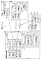
- the communication system 2 includes an image display device 10, a tool 40, a server 50, and an external PC (abbreviation for personal computer) 70.
- the image display device 10, the server 50, and the external PC 70 can perform wireless communication (specifically, Wi-Fi communication) with each other via the Internet 4 (see solid arrows in the figure).
- the image display apparatus 10 and the tool 40 can execute Bluetooth (registered trademark) communication (hereinafter referred to as “BT communication”) (see the broken line arrow in the figure).
- BT communication registered trademark
- the image display device 10 is an image display device (a so-called head mounted display) used by being mounted on a user's head. As shown in FIG. 1, the image display device 10 includes a support 12, display units 14 a and 14 b, projection units 15 a and 15 b, a first camera 16, a second camera 18, and a control box 19. It has.
- the support 12 is a spectacle frame-shaped member.
- the user can wear the image display device 10 on the head by wearing the support 12 like wearing glasses.
- the display units 14a and 14b are translucent display members, respectively. When the user wears the image display device 10 on the head, the display unit 14a is disposed at a position facing the user's right eye, and the display unit 14b is disposed at a position facing the left eye.
- the left and right display units 14a and 14b may be collectively referred to as the display unit 14.
- the projection units 15a and 15b are members that project images onto the display units 14a and 14b.
- the projection units 15a and 15b are provided on the side portions of the display units 14a and 14b.
- the left and right projection units 15a and 15b may be collectively referred to as the projection unit 15.
- the projection unit 15 projects a predetermined object image on the display unit 14 in accordance with an instruction from the control unit 26.
- the user can view the real-world object or / and space as if the object image was synthesized at a predetermined position in the real-world object or / and space that can be visually recognized by the user through the display unit 14. And the object image.
- control unit 26 displays a desired screen on the display unit 14 by instructing the projection unit 15 to project an image
- the operation of the projection unit 15 will be described. It may be omitted and simply expressed as “the control unit 26 causes the display unit 14 to display a desired image”.
- the first camera 16 is a camera arranged on the support 12 at a position above the display unit 14a (that is, a position corresponding to the right eye of the user).
- the 2nd camera 18 is a camera arrange
- Each of the first camera 16 and the second camera 18 can capture a range corresponding to the field of view of the user wearing the image display device 10 (hereinafter referred to as a “specific range”) from different angles.
- the control box 19 is a box attached to a part of the support 12.
- the control box 19 accommodates each element that controls the control system of the image display apparatus 10. Specifically, as shown in FIG. 2, the control box 19 accommodates a sensor 20, a BT interface 22, a Wi-Fi interface 24, a control unit 26, and a memory 28.
- the interface is described as “I / F”.
- Sensor 20 is a three-axis acceleration sensor.
- the sensor 20 detects acceleration of three axes of X, Y, and Z.
- the control unit 26 can specify the posture and motion state of the image display device 10.
- BTI / F 22 is an I / F for executing BT communication with an external device (for example, tool 40).
- the Wi-Fi I / F 24 is an I / F for executing Wi-Fi communication with an external device (for example, the server 50) via the Internet 4.
- the control unit 26 executes various processes according to the program stored in the memory 28. The contents of the processing executed by the control unit 26 will be described in detail later.
- the control unit 26 is electrically connected to the display unit 14, the projection unit 15, the first camera 16, the second camera 18, the sensor 20, the BTI / F 22, the Wi-Fi I / F 24, and the memory 28. The operation of each of these elements can be controlled.
- the memory 28 stores various programs.
- the program includes various application programs such as a manual application program 30.
- the manual application program 30 is displayed as “manual application 30”.
- the manual application may be simply referred to as “manual application”.
- the “manual application” is an application for instructing how to handle an article (for example, assembly, disassembly, use, repair, etc.) using a real image and an object image (that is, a virtual image).
- the control unit 26 executes manual processing (see FIG. 6) described later according to the manual application 30.
- the manual application 30 includes an article table 32 (see FIG. 8) and manual data 34.
- the article table 32 includes data related to articles whose handling method is instructed according to the manual application 30.
- the manual data 34 includes a manual for explaining how to handle the article for each of the plurality of articles.
- the memory 28 also has a list storage area 36 for storing a procedure list (see FIGS. 8 and 9) generated along with manual processing (see FIG. 6) described later.
- the memory 28 also stores an ID assigned to the image display device 10. As shown in FIGS. 1 and 2, the ID of the image display apparatus 10 of the present embodiment is “D1”.
- image display device 10 In the example of FIG. 1, only one image display device 10 is illustrated, but a plurality of image display devices 10 may exist in the actual communication system 2. In that case, a different ID is assigned to each image display device 10.
- the tool 40 is a screwdriver tool (so-called driver) that is gripped and used by a user.
- the tool 40 includes a control unit 42, a memory 44, and a BTI / F 46.
- the BTI / F 46 is an I / F for executing BT communication with an external device (for example, the image display device 10).
- the control unit 42 executes processing for transmitting operation information related to the operation content of the tool to the image display device 10 via the BTI / F 46 according to the program stored in the memory 44. Specifically, the control unit 42 executes a process of detecting a torque value when tightening the screw and transmitting operation information including the detected torque value to the image display device 10 via the BTI / F 46.
- the memory 44 stores various programs.
- the server 50 in FIGS. 1 and 2 is a server installed by an administrator of the image display apparatus 10 (for example, a company that provides the image display apparatus 10).
- the server 50 manages the handling results of articles by the user of the image display device 10.
- the server 50 includes a display unit 52, an operation unit 54, a Wi-Fi I / F 56, a control unit 58, and a memory 60.
- the display unit 52 is a display capable of displaying various information.
- the operation unit 54 includes a keyboard and a mouse.
- the user of the server 50 can input various instructions to the server 50 by operating the operation unit 54.
- the Wi-Fi I / F 56 is an I / F for performing Wi-Fi communication with external devices (for example, the image display device 10 and the external PC 70) via the Internet 4.
- the control unit 58 executes various processes according to programs stored in the memory 60.
- the memory 60 stores various programs. Further, the memory 60 stores work information received from the image display device 10 when the image display device 10 executes manual processing (see FIG. 7).
- the external PC 70 in FIGS. 1 and 2 is a PC used by an administrator of the image display apparatus 10 (for example, a company that provides the image display apparatus 10).
- the external PC 70 is used to access the server 50 and browse the handling results of articles by the user of the image display device 10.
- the external PC 70 also includes a display unit 71, an operation unit 72, a Wi-Fi I / F 73, a control unit 74, and a memory 75.
- the display unit 71 is a display capable of displaying various information.
- the operation unit 72 includes a keyboard.
- the user of the external PC 70 can input various instructions to the server 50 by operating the operation unit 72.
- the Wi-Fi I / F 73 is an I / F for executing Wi-Fi communication with the server 50 via the Internet 4.
- the control unit 74 executes various processes according to programs stored in the memory 75.
- the memory 75 stores various programs. In the present embodiment, in particular, the memory 75 stores a browsing program 76 for allowing the external PC 70 to communicate with the server 50 and browsing work information stored in the server 50.
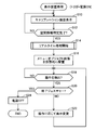
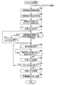
- Display device processing FIG. 3
- the display device process executed by the control unit 26 of the image display device 10 will be described.
- the control unit 26 starts the display device processing of FIG.
- the control unit 26 displays a predetermined calibration screen on the display unit 14.
- the calibration screen is a screen for allowing the user to perform calibration.
- “calibration” is a process for specifying spatial information (that is, calibration data) for specifying the characteristics of the space around the image display device 10.
- the “characteristic of the space around the image display device 10” includes, for example, when the image display device 10 is present indoors, the distance between the wall and the own device, the direction of the wall, the distance between the ceiling and the own device, the ceiling Various information for characterizing the indoor space, such as the height of the room, the floor area, the position of the furniture, and the distance to the furniture.
- the “characteristics of the space around the image display device 10” are various types for characterizing the space around the own device such as the distance to the surrounding target. Contains information.
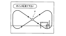
- Figure 4 shows an example of the calibration screen.
- the calibration screen includes a pointer P and a message for prompting the user to follow the pointer with a line of sight.
- the control unit 26 moves the pointer P in the display unit 14 so that the user can follow the pointer P with a line of sight so that the entire space around the image display device 10 can be put into view.
- the control unit 26 monitors that the identification of the spatial information is completed.
- the user follows the pointer P with a line of sight (that is, the user moves his / her head in accordance with the movement of the pointer P).
- Each direction of the surrounding space is photographed by the first camera 16 and the second camera 18.
- the control unit 26 acquires, from the first camera 16, a first calibration image that is an image of a specific range (that is, a range corresponding to the user's view range) captured by the first camera 16.
- a second calibration image that is an image in a specific range photographed by the second camera 18 is acquired from the second camera 18.
- the control unit 26 calculates a distance between the feature point and the image display device 10 by identifying a feature point common to the first calibration image and the second calibration image and performing triangulation. be able to. Furthermore, the control unit 26 can also specify the coordinates of the position of the feature point based on the coordinates of the initial position of the pointer P. The control unit 26 performs the same processing for each of a plurality of feature points existing in all directions around the image display device 10. When the distance from the feature point and the coordinates of the feature point are specified for each of a plurality of feature points existing in all directions around the image display device 10, the control unit 26 determines YES in S12. Proceed to S14. That is, the “spatial information for specifying the features of the space around the image display device 10” in S12 means the distance to each feature point and the coordinates of each feature point.
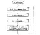
- control unit 26 starts real-time processing (see FIG. 5).
- the control unit 26 repeatedly executes the real-time process until the image display apparatus 10 is powered off.
- the control unit 26 proceeds to S16.
- the control unit 26 acquires, from the first camera 16, a first captured image that is an image in a specific range captured by the first camera 16 at the time of S30, and the second The second captured image that is an image in a specific range captured by the second camera 18 at the time of S30 is acquired from the first camera 18. That is, the first captured image and the second captured image acquired in S30 are both real-time captured images corresponding to the current visual field range of the user.
- the control unit 26 calculates a distance between a specific feature point common to the first captured image and the second captured image and the image display device 10.
- the “feature point” referred to here is, for example, one of a plurality of feature points included in the spatial information (in the case of YES in S12 of FIG. 3).
- the distance between the feature point and the image display device 10 is calculated by performing triangulation using the first captured image and the second captured image, as in the above case.
- the control unit 26 calculates the attitude of the image display device 10 at this time based on the detection value of the sensor 20. Specifically, the control unit 26 determines whether the gravity direction is 0 ° based on the detection values of the sensor 20 (that is, accelerations in the X-axis, Y-axis, and Z-axis directions). The tilt angles ( ⁇ x, ⁇ y, ⁇ z) of the axis and the Z axis are calculated, and the attitude of the image display device 10 at the time of S10 (that is, the tilt with respect to the horizontal plane) is calculated based on these tilt angles.
- control unit 26 determines the distance between the spatial information identified in the case of YES in S12 of FIG. 3 and the feature point calculated in S32, the attitude of the image display device 10 calculated in S34, and Is used to specify the position and orientation of the image display device 10 in the space where the image display device 10 exists.
- control unit 26 When S36 is finished, the control unit 26 returns to S30 and repeatedly executes each process of S30 to S36. That is, the control unit 26 can specify the position and orientation of the image display device 10 in the space where the image display device 10 exists in real time by repeatedly executing the processes of S30 to S36.
- the control unit 26 starts real-time processing (see FIG. 5) in S14 of FIG. 3, the control unit 26 proceeds to S16.
- the control unit 26 generates a menu object image representing the main menu object and associates it with a predetermined position.
- the control unit 26 generates a menu object image and virtually arranges it at a predetermined position.
- “the menu object image is virtually arranged at a predetermined position” means that the menu is displayed when the predetermined range is included in the specific range (that is, the imaging range of the first camera 16 and the second camera 18).
- the menu object image is associated with a predetermined position so that a screen in a state where the object image is arranged at a predetermined position in the space is displayed on the display unit 14.
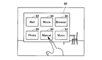
- the control unit 26 virtually arranges the menu object image by designating the position in front of the user's field of view as the predetermined position. Therefore, at the time of the process of S16, the predetermined position is included in the specific range (that is, the user's view range). Therefore, as shown in FIG. 6, the display unit 14 displays a screen in a state where the menu object image 80 indicating the menu object is arranged in the space.
- the display unit 14 is a translucent display, the user can display an aspect in which the menu object image 80 is combined with an actual article (that is, an indoor scene) that can be viewed through the display unit 14. Can see.
- the menu object image 80 represents the main menu.
- six selectable icons 82 to 92 are displayed. Each icon corresponds to each application.
- icon 82 indicates a mail application
- icon 84 indicates a movie application
- icon 86 indicates a browser application
- icon 88 indicates a photo application
- icon 90 indicates a manual application
- icon 92 indicates a music application.
- the user can activate an application corresponding to a desired icon by performing a gesture of touching the desired icon within a specific range.
- the control unit 26 monitors the detection of a user operation within a specific range.
- “user operation within a specific range” is a gesture that the user performs on an object image such as a menu object image (for example, a gesture for instructing movement or size change of an image, an instruction to end display of an image) Gestures, a gesture for selecting an icon, a gesture for instructing power-off of the image display apparatus 10), movement of the user in the space, change of the user's viewing direction, and the like.
- the control unit 26 determines the user within a specific range based on the first captured image from the first camera 16, the second captured image from the second camera 18, and the detection value of the sensor 20. It is determined whether or not an operation has been performed. When it is detected that the user has performed an operation within the specific range, the control unit 26 determines YES in S18 and proceeds to S20.
- the control unit 26 determines whether or not the operation performed by the user is a predetermined gesture (hereinafter referred to as “end gesture”) instructing to turn off the image display device 10.
- end gesture a predetermined gesture
- the control unit 26 determines YES in S20, proceeds to S24, and turns off the power of the image display apparatus 10. In this case, the display device process in FIG. 3 ends. In this case, the real-time processing of FIG.
- the control unit 26 determines NO in S20 and proceeds to S22.
- the control unit 26 executes processing according to the operation. For example, when the operation performed by the user is an operation for moving the display position of the menu object image 80 (see FIG. 6), the control unit 26 changes the display position of the menu object image 80 according to the user's operation. In that case, the display unit 14 displays a screen in which the menu object image 80 is arranged at the changed position. For example, as illustrated in FIG. 6, when the operation performed by the user is an operation of selecting the manual application icon 90 in the menu object image 80 (for example, an operation of touching the icon 90), the control unit 26 activates the manual application according to the user's operation. When the manual application is activated, the control unit 26 starts the manual process of FIG. The contents of manual processing will be described in detail later.
- control unit 26 When the control unit 26 finishes S22, the control unit 26 returns to S18 and monitors that the user operation is performed again. Thereby, whenever the user performs a gesture within a specific range or the user performs an operation of changing the direction of the line of sight, the control unit 26 displays the object image and the guide image displayed on the display unit 14 according to the operation. The display position and display mode are changed. The control unit 26 repeatedly executes each process of S18 to S22 until the end gesture is performed (YES in S20).
- the control unit 26 based on the first photographed image from the first camera 16 and the second photographed image from the second camera 18, is an article (hereinafter referred to as “ In some cases, it may be referred to as “target article”. Specifically, in S50, the control unit 26 determines the characteristics (for example, shape, color, material) of the target article based on the images of the target article included in the first captured image and the second captured image. Etc.).
- the control unit 26 specifies the article ID of the target article having the feature recognized in S50. Specifically, in S ⁇ b> 52, the control unit 26 determines whether or not the article having the feature recognized in S ⁇ b> 50 is included in the article table 32 in the memory 28. As shown in FIG. 8, the article table 32 includes a plurality of combination information 102, 104, 106, and the like in which an article ID (for example, “article P1”) is associated with feature data.
- the feature data includes data for characterizing the article, such as the shape, material, and color of the article corresponding to the article ID.
- the control unit 26 specifies combination information including feature data indicating similar features.
- control unit 26 specifies an article ID included in the specified combination information. If control part 26 specifies article ID, it will progress to S54. On the other hand, when the article ID cannot be specified in S52 (that is, when the article having the feature recognized in S50 is not included in the article table 32), the control unit 26 ends the manual process with an error.
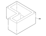
- the control unit 26 when the target article is the resin-made white casing 400 having the shape shown in FIG. 11, in S52, the control unit 26 includes a combination including feature data indicating features similar to the features of the casing 400. Information 102 is specified. Then, the control unit 26 specifies the article ID “P1” included in the specified combination information 102.
- the control unit 26 reads a manual corresponding to the article ID specified in S52 from the manual data 34 (see FIG. 2).
- the manual data 34 includes a plurality of manuals.
- the manual data 34 includes a manual for explaining a method of handling an article corresponding to the article ID (for example, an assembly method, a disassembly method, a repair method, etc.) for each article ID.
- control unit 26 In subsequent S55, the control unit 26 generates a procedure list using the manual read in S54. 9 and 10 show examples of procedure lists.
- the procedure list 200 in FIG. 9 is an example when the article ID “P1” (see the combination information 102 in FIG. 8) is specified in S52.
- the procedure list 200 includes the ID “D1” of the image display device 10, the creation date and time of the procedure list 200 (“2015.Dec.18 10:00”), and the last update date and time of the procedure list 200 (“2015.Dec.18 10”). : 25 ”).
- the procedure list 200 includes a procedure column indicating procedures for handling the article with the article ID “P1” (“cover”, “screw”, etc.), and operations according to those procedures. It includes a procedure table 202 combined with a result column indicating a result of “No” (“OK”, “NG”, etc.). At the time when the procedure list 200 is created in S55, each result column includes “NG” indicating that the operation according to the corresponding procedure has not been executed.
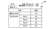
- the procedure list 300 includes a procedure table 302 in which a procedure column indicating a procedure for handling an item with the item ID “P2” and a result column indicating whether or not those procedures are completed are combined. .
- the contents of each procedure included in the procedure table 302 are different from the contents of each procedure included in the procedure table 202 of FIG.
- the control unit 26 displays a procedure list at an arbitrary timing according to the user's operation even before the work is completed. Can be displayed on the display unit 14.
- the control unit 26 determines whether or not the arrangement direction of the target article existing in the specific range matches the specific arrangement direction specified by the manual read in S54. When the arrangement direction of the target article matches the specific arrangement direction, the control unit 26 determines YES in S56 and proceeds to S58. On the other hand, when the arrangement direction of the target article does not coincide with the specific arrangement direction, the control unit 26 determines NO in S56 and proceeds to S57. In S57, the control unit 26 displays on the display unit 14 a message for prompting the user to change the arrangement direction of the target article to a specific arrangement direction. When S57 ends, the control unit 26 returns to the determination of S56.
- control unit 26 causes the display unit 14 to display an instruction screen for instructing the first procedure according to the procedure list created in S55.
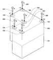
- the target article is the casing 400 shown in FIG.
- the first procedure is “cover”. Therefore, as shown in FIG. 12, in S58, when the target article (that is, the casing 400) is present in the specific range, the control unit 26 adds “the lid to the article image (that is, the actual image) of the target article.
- An instruction screen in which an object image 500 for explaining the “cover” procedure is incorporated is displayed on the display unit 14. As illustrated in FIG.
- the object image 500 includes an image virtually showing a lid and an image of an arrow for instructing the virtual lid to cover the opening of the housing 400.
- the image of the lid is displayed in a color different from that of the housing 400 so that the user can easily see it.
- the instruction screen in FIG. 12 is a screen for instructing to “cover” the opening of the casing 400 that is the target article.
- the control unit 26 monitors that an operation in accordance with a procedure instructed on the instruction screen displayed in S58 (hereinafter may be referred to as “specific procedure”) is actually performed. .
- the control unit 26 determines whether or not an operation according to a specific procedure has been performed based on at least one of the first captured image, the second captured image, and the operation information received from the tool 40. To do.
- the control unit 26 determines YES in S60 and proceeds to S62.
- the control unit 26 does not determine YES in S60 while determining that the operation according to the specific procedure is not performed.
- the control unit 26 determines that “the operation according to the specific procedure is not performed”, for example, when the component to be attached is incorrect, when the screw tightening torque value is lower than a predetermined value, This includes various cases such as when an operation is performed.
- the control unit 26 causes the housing 400 to It is monitored that a cover (see reference numeral 600 in FIG. 13) is actually put on the opening. The user can put an actual lid over the opening of the housing 400 while viewing the instruction screen of FIG. If the control unit 26 determines that the cover is actually covered on the opening of the housing 400 as instructed on the instruction screen based on the first and second captured images, YES in S60. Judge, and proceed to S62.
- control unit 26 updates the procedure list. That is, the control unit 26 records in the procedure list created in S55 that the operation according to the procedure instructed on the instruction screen in S58 has been performed.
- the control unit 26 causes the procedure list 200 ( In the procedure table 202 of FIG. 9), the result corresponding to the “cover” procedure is changed from “NG” to “OK”. Further, the control unit 26 updates the last update date / time.
- the control unit 26 determines whether or not all the procedures are completed. Specifically, the control unit 26 determines whether all the procedures indicated by the procedure list created in S55 have been completed (that is, whether “OK” is included in the result column). If all the procedures indicated by the procedure list created in S55 have been completed, the control unit 26 determines YES in S64 and proceeds to S66. On the other hand, if all the procedures indicated by the procedure list created in S55 are not completed at the time of S64, the control unit 26 determines NO in S64 and returns to S58. In this case, the control unit 26 repeatedly executes each process of S58 to S62 until it determines YES in S64.
- ⁇ H6 and an object image 800 for indicating a screw to be screwed in are displayed.
- the object image 700 is displayed together with the characters “H1” to “H6” so that the screw holes H1 to H6 can be distinguished.
- the object image 800 is displayed together with the letters “A” or “B” so that the type of screw (screw A, screw B) can be discriminated.
- the control unit 26 monitors whether screws are actually screwed into the screw holes H1 to H6.
- the user can screw an actual screw into each of the screw holes H1 to H6 using the tool 40 while viewing the instruction screen of FIG.
- the user inserts a screw (screw A or screw B) of a type suitable for each of the screw holes H1 to H6.
- the screw A is adapted to the screw holes H1, H2, H5, and H6, and the screw B is adapted to the screw holes H3 and H4.
- the tool 40 detects a torque value when the user tightens the screw, and transmits operation information including the detected torque value to the image display device 10 via the BTI / F 46.
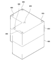
- the control unit 26 receives operation information via the BTI / F 22. Based on the first photographed image, the second photographed image, and the operation information, the control unit 26 determines whether or not the screws are correctly screwed into the screw holes H1 to H6 with a predetermined tightening torque value. To do. If the control unit 26 determines that the screws are correctly screwed into the screw holes H1 to H6 with a predetermined tightening torque based on the first photographed image, the second photographed image, and the operation information, in S60. It judges YES and progresses to S62. In this case, as shown in FIG. 14, a cover 600 is placed on the casing 400, and the target article screwed by the six screws 900 is completed.
- the control unit 26 changes each result corresponding to the “screw tightening” procedure from “NG” to “OK” in the procedure table 202 of the procedure list 200 (FIG. 9). To do.
- the control unit 26 changes the result of each result column from “NG” to “OK”.
- the control part 26 updates the last update date.
- the procedure list 200 in which “OK” is recorded in all the result columns of the procedure table 202 is completed.
- the control unit 26 determines YES in the subsequent second S64, and proceeds to S66.
- control unit 26 stores the completed procedure list in the list storage area 36 of the memory 28.
- control unit 26 In subsequent S68, the control unit 26 generates work information including the procedure list stored in the list storage area 36, and transmits the work information to the server 50 via the Wi-Fi I / F 24.
- the work information includes various information (for example, transmission date and time) in addition to the procedure list.
- the control unit 26 interrupts the process and forcibly proceeds to S66 regardless of which process of S55 to S64 is being executed.
- the control unit 26 stores the procedure list at this time in the list storage area 36 of the memory 28.
- the control unit 26 stores a procedure list including “NG” in the result column in the list storage area 36 as in the procedure list 300 of FIG.
- the control unit 26 generates work information including the procedure list stored in the list storage area 36, and transmits the work information to the server 50 via the Wi-Fi I / F 24. And the control part 26 complete
- the procedure list is stored in the list storage area 36 of the memory 28 by executing the manual processing of FIG.
- the user of the image display device 10 can perform an operation for browsing the procedure list in the list storage area 36 within a specific range.
- the control unit 26 can read out the procedure list designated by the user from the list storage area 36 and cause the display unit 14 to display a screen representing the procedure list.
- the user can confirm whether or not the target article has been appropriately handled by looking at the procedure list displayed on the display unit 14.
- the user of the server 50 can input a browsing request for browsing the work information in the memory 60 to the server 50 by operating the operation unit 54.
- the control unit 58 reads the work information designated by the browsing request from the memory 60 and causes the display unit 52 to display a screen represented by the work information.
- the screen represented by the work information includes information similar to the procedure list (see FIGS. 9 and 10).
- the user of the server 50 can confirm whether or not the target article has been appropriately handled by the user of the image display device 10 by looking at the screen displayed on the display unit 52.
- the user of the external PC 70 can input an operation for browsing the work information in the server 50 to the external PC 70 by operating the operation unit 72.
- the control unit 74 of the external PC 70 can transmit a request signal for browsing work information in the memory 60 to the server 50 via the Wi-Fi I / F 73.
- the control unit 58 receives the request signal via the Wi-Fi I / F 56. Then, the control unit 58 reads out the work information specified by the request signal from the memory 60 and transmits the read work information to the external PC 70 via the Wi-Fi I / F 56.
- the control unit 74 of the external PC 70 receives the work information via the Wi-Fi I / F 73.
- the control unit 74 can cause the display unit 71 to display a browsing screen represented by the received work information.
- the browsing screen represented by the work information includes information similar to the procedure list (see FIGS. 9 and 10).
- the user of the external PC 70 can also check whether or not the target article has been appropriately handled by the user of the image display device 10 by looking at the browsing screen displayed on the display unit 71.
- the control unit 26 of the image display device 10 is configured to display the first captured image and the second captured image while the instruction screen (for example, see FIG. 12) is displayed on the display unit 14. Based on the image, it is determined whether or not the operation actually performed by the user on the target article within the specific range is in accordance with the procedure instructed on the instruction screen (S60 in FIG. 7).
- the control unit 26 can record the result in the procedure list and store it in the memory 28 (S66). Therefore, the user of the image display device 10 can check whether or not the target article has been handled according to the procedure indicated by the manual by browsing the procedure list stored in the memory 28.
- the control unit 26 of the image display device 10 follows the specific procedure.
- An instruction screen (see FIG. 13) for instructing the procedure is displayed on the display unit 14. That is, when it is determined that the specific procedure is not completed (NO in S60), the control unit 26 does not display the instruction screen for instructing the execution of the next procedure on the display unit 14. Therefore, there is a high possibility that the user of the image display apparatus 10 can appropriately handle the target article according to the procedure indicated by the manual.
- the control unit 26 of the image display device 10 receives operation information including a torque value when the user tightens the screw from the tool 40 via the BTI / F 22. Therefore, the control unit 26 adds screws to the screw holes H1 to H6 with a predetermined tightening torque value based on the operation information received from the tool 40 in addition to the first captured image and the second captured image. It is determined whether or not the screw has been correctly inserted (S60). Therefore, the control unit 26 can appropriately determine whether or not the screw is correctly screwed into each of the screw holes H1 to H6 with a predetermined tightening torque.
- control unit 26 of the image display device 10 generates work information including a procedure list stored in the list storage area 36 and transmits the work information to the server 50 via the Wi-Fi I / F 24 ( S68). As a result, work information is accumulated in the server 50.
- the user of the server 50, the user of the external PC 70, and the like can confirm whether or not the target article has been handled appropriately by looking at the screen displayed according to the work information stored in the server 50.
- the “cover cover” procedure in the procedure table 202 of FIG. 9 is an example of the “first procedure”.
- An object image 500 in FIG. 12 is an example of a “first object image”.
- the instruction screen of FIG. 12 is an example of a “first instruction screen”.
- the “tightening screw” procedure in the procedure table 202 of FIG. 9 is an example of the “second procedure”.
- the object images 700 and 800 in FIG. 13 are examples of the “second object image”.
- the instruction screen of FIG. 13 is an example of a “second instruction screen”.
- the BTI / F 22 is an example of a “reception unit”.
- Wi-Fi I / F 24 is an example of a “transmission unit”.
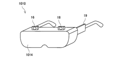
- an image display device 1010 of the second embodiment will be described focusing on differences from the first embodiment.
- This embodiment is different from the first embodiment in that the display unit 1014 is a light-shielding display and blocks the user's field of view when the user wears the image display device 1010.
- Other components are almost the same as those in the first embodiment.
- the control unit 26 sets the first area in the region facing the right eye of the user.
- a captured image that is, a captured image of the first camera 16
- a second captured image that is, a captured image of the second camera 18
- the control unit 26 displays a screen in which the menu object image 80 is combined with the first captured image and the second captured image. To display.
- the control unit 26 displays the first captured image in a region facing the user's right eye, and the second captured image in the region facing the user's left eye. Is displayed. Without being limited thereto, the control unit 26 may display only one of the first captured image and the second captured image on the display unit 1014. Further, the control unit 26 may display an image obtained by combining the first captured image and the second captured image on the display unit 1014.
- the control unit 26 monitors whether a user operation within a specific range is detected. Is not limited to gestures performed on an object image such as a menu object image, movement of a user in a space, change of a user's visual field direction, and the like, including operations that a user inputs via input means (such as input keys) But you can.
- the image display apparatuses 10 and 1010 may further include an input unit.
- the control unit 26 starts real-time processing (S14) after executing calibration (YES in S10 and S12 in FIG. 3).
- the present invention is not limited to this, and the control unit 26 may start real-time processing along with the execution of calibration.
- the “first calibration image” and the “first photographed image” may be the same image, or the “second calibration image” and the “second photographed image” are the same image. It may be.
- each of the image display devices 10 and 1010 has a substantially glasses-like support frame, and can be worn on the user's head like wearing glasses. It is.
- the image display device is not limited to this, and may have an arbitrary support frame such as a hat shape or a helmet shape as long as the image display device can be mounted on the user's head.
- the image display device includes a first camera 16 and a second camera 18 in eyewear (glasses, sunglasses, etc.) generally used for purposes such as vision correction and eye protection. And by attaching the control box 19. In that case, the lens portion of the eyewear may be used as the display unit.
- the control unit 26 recognizes the feature of the target article based on the first photographed image and the second photographed image (S50 in FIG. 7), and then recognized.
- the product ID of the target product having characteristics is specified based on the product table 32 (see FIG. 8) (S52).
- the method by which the control unit 26 specifies the item ID of the target item is not limited to this, and any method can be adopted. For example, an information code in which an article ID is recorded on the target article is attached in advance, and the control unit 26 decodes the information code included in the first photographed image and the second photographed image, thereby the article. An ID may be specified.
- the tool 40 is not limited to a screwdriver tool (so-called driver) that is gripped and used by the user, and may be any other type of tool (for example, a spanner, a caliper, etc.). Even in this case, the tool 40 only needs to be able to transmit operation information to the image display device 10.
- driver screwdriver tool
- the tool 40 only needs to be able to transmit operation information to the image display device 10.
- the various object images of the menu object image 80 (FIG. 6) and the object images 500, 700, and 800 (FIGS. 12 and 13) are all displayed as still images.
- the present invention is not limited to this, and various object images may be displayed as moving images (that is, images in which at least a part is animated).
- Modification 9 In each of the embodiments described above, when it is determined that the specific procedure is not completed (NO in S60 of FIG. 7), the control unit 26 instructs to specify the specific procedure.
- the screen that is, the screen including the object image
- the control unit 26 is not limited to this. Even when it is determined that the specific procedure is not completed, the control unit 26 satisfies the predetermined condition (for example, when a predetermined time has elapsed from the start of display of the instruction screen, The display of the instruction screen may be terminated when at least part of the specific procedure is completed).
- This modification is also an example in which the control unit 26 “displays the instruction screen on the display unit”.
- control unit 26 monitors that the operation indicated by the specific procedure is actually performed (that is, completed).
- the control unit 26 is not limited to this, and in S60 of FIG. 7, the control unit 26 determines whether the operation indicated by the specific procedure has been completed or not, and the operation stage of the operation indicated by the specific procedure (for example, unworked, working, completed Etc.) may be determined at the same time.
- the procedure tables 202 and 302 in the procedure lists 200 and 300 are the procedures for handling the article having the article ID “P1” (“cover the cover”). ”,“ Tighten screws ”, etc.) and a result column showing the result (“ OK ”,“ NG ”, etc.) indicating whether or not an operation according to these procedures has been performed.
- a remarks column may be further combined in addition to the procedure column and the result column. In the remarks column, for example, various information such as a reason when the result is “NG” may be recorded. In this case, in S60 of FIG.
- the control unit 26 determines that the operation indicated by the specific procedure is not completed, the reason for determining that the operation indicated by the specific procedure is not completed (for example, screwing). It is also possible to determine whether the screw to be inserted does not exist in the surroundings, the torque when tightening the screw is less than a predetermined value, or the like. In that case, the control unit 26 may record the reason for determining that the operation indicated by the specific procedure is not completed in the remarks column of the procedure tables 202 and 302. In this modification, the work information generated in S68 of FIG. 7 may further include information recorded in the remarks column.
- the control unit 26 instructs the execution of the next procedure. Is not displayed on the display unit 14.
- the present invention is not limited to this, and the control unit 26 may display an instruction screen for instructing execution of the next procedure on the display unit 14 according to a user operation even before the specific procedure is completed. Good.
- the control unit 26 displays an instruction screen for a previous procedure that has already been completed in response to a user operation even while an instruction screen for instructing execution of a specific procedure is displayed on the display unit 14. May be redisplayed.
- a skippable procedure that is, a procedure that does not affect the handling of the target article even if it is not completed. It may be.
- the skippable procedures include, for example, incidental procedures such as “clean the surroundings between operations” and “apply a decorative sticker on the surface of the target article”.
- the control unit 26 displays an instruction screen for instructing a skippable procedure on the display unit 14, even before the skippable procedure is completed, according to a user operation.
- An instruction screen for instructing execution of the next procedure may be displayed on the display unit 14.
Landscapes
- Engineering & Computer Science (AREA)
- Business, Economics & Management (AREA)
- General Physics & Mathematics (AREA)
- Theoretical Computer Science (AREA)
- Physics & Mathematics (AREA)
- Tourism & Hospitality (AREA)
- Human Resources & Organizations (AREA)
- Strategic Management (AREA)
- Economics (AREA)
- General Business, Economics & Management (AREA)
- Marketing (AREA)
- Health & Medical Sciences (AREA)
- General Health & Medical Sciences (AREA)
- Primary Health Care (AREA)
- Entrepreneurship & Innovation (AREA)
- Manufacturing & Machinery (AREA)
- Educational Administration (AREA)
- Educational Technology (AREA)
- Computer Vision & Pattern Recognition (AREA)
- Operations Research (AREA)
- Quality & Reliability (AREA)
- Multimedia (AREA)
- User Interface Of Digital Computer (AREA)
- General Factory Administration (AREA)
- Processing Or Creating Images (AREA)
- Management, Administration, Business Operations System, And Electronic Commerce (AREA)
Abstract
Description
(通信システム2の構成;図1、図2)
図1、図2に示すように、通信システム2は、画像表示装置10と、工具40と、サーバ50と、外部PC(Personal Computerの略)70とを備える。画像表示装置10と、サーバ50と、外部PC70は、インターネット4を介して相互に無線通信(具体的には、Wi-Fi通信)を実行可能である(図中の実線矢印参照)。また、画像表示装置10と工具40は、相互にBluetooth(登録商標)通信(以下では「BT通信」と呼ぶ)を実行可能である(図中の破線矢印参照)。
画像表示装置10は、ユーザの頭部に装着して用いられる画像表示装置(いわゆるヘッドマウントディスプレイ)である。図1に示すように、画像表示装置10は、支持体12と、表示部14a、14bと、投影部15a、15bと、第1のカメラ16と、第2のカメラ18と、コントロールボックス19とを備えている。
図1に示すように、工具40は、ユーザが把持して利用するねじ回し用工具(いわゆるドライバー)である。図2に示すように、工具40は、制御部42と、メモリ44と、BTI/F46とを備えている。
図1、図2のサーバ50は、画像表示装置10の管理者(例えば、画像表示装置10を提供する企業等)によって設置されるサーバである。サーバ50は、画像表示装置10のユーザによる物品の取り扱い実績を管理する。サーバ50は、表示部52と、操作部54と、Wi-FiI/F56と、制御部58と、メモリ60とを備える。
図1、図2の外部PC70は、画像表示装置10の管理者(例えば、画像表示装置10を提供する企業等)が使用するPCである。外部PC70は、サーバ50にアクセスして、画像表示装置10のユーザによる物品の取り扱い実績を閲覧するために利用される。外部PC70も、サーバ50と同様に、表示部71と、操作部72と、Wi-FiI/F73と、制御部74と、メモリ75とを備える。
図3を参照して、画像表示装置10の制御部26が実行する表示装置処理について説明する。ユーザが画像表示装置10を自身の頭部に装着し、画像表示装置10の電源をオンすると、制御部26は、図3の表示装置処理を開始する。
図5のS30では、制御部26は、第1のカメラ16から、S30の時点で第1のカメラ16によって撮影されている特定範囲の画像である第1の撮影画像を取得するとともに、第2のカメラ18から、S30の時点で第2のカメラ18によって撮影されている特定範囲の画像である第2の撮影画像とを取得する。即ち、S30で取得される第1の撮影画像及び第2の撮影画像は、いずれも、ユーザの現時点の視界範囲に相当するリアルタイムの撮影画像である。
上記の通り、制御部26は、図3のS14でリアルタイム処理(図5参照)を開始すると、S16に進む。S16では、制御部26は、メインメニューオブジェクトを表すメニューオブジェクト画像を生成し、所定位置に対応付ける。言い換えると、制御部26は、メニューオブジェクト画像を生成し、所定位置に仮想的に配置する。ここで、「メニューオブジェクト画像を所定位置に仮想的に配置する」とは、特定範囲(即ち、第1のカメラ16及び第2のカメラ18の撮像範囲)に所定位置が含まれる場合に、メニューオブジェクト画像が空間内の所定位置に配置された状態の画面が表示部14に表示されるように、メニューオブジェクト画像を所定位置に対応付けることを意味する。なお、S16では、制御部26は、ユーザの視界の正面の位置を所定位置として指定して、メニューオブジェクト画像を仮想的に配置する。そのため、S16の処理の時点では、特定範囲(即ちユーザの視界範囲)に所定位置が含まれる。そのため、図6に示すように、表示部14には、メニューオブジェクトを示すメニューオブジェクト画像80が空間内に配置された状態の画面が表示される。本実施例では、表示部14は透光性のディスプレイであるため、ユーザは、表示部14越しに視認できる現実の物品(即ち、室内の光景)にメニューオブジェクト画像80が合わされた態様の表示を見ることができる。
図7を参照して、画像表示装置10の制御部26が実行するマニュアル処理について説明する。上記の通り、ユーザの操作によってマニュアルアプリが起動されると、制御部26は、マニュアル処理を開始する。
続いて、サーバ50の制御部58が実行する処理について説明する。上記の通り、画像表示装置10の制御部26がマニュアル処理(図7参照)を実行することにより、画像表示装置10からサーバ50に作業情報が送信される。サーバ50の制御部58は、Wi-FiI/F56を介して、作業情報を受信する。制御部58は、受信した作業情報をメモリ60に記憶させる。
以上、本実施例の通信システム2の構成、動作について説明した。上記の通り、本実施例では、画像表示装置10の制御部26は、表示部14に指示画面(例えば図12参照)が表示されている間に、第1の撮影画像と、第2の撮影画像と、に基づいて、特定範囲内の対象物品に対してユーザが実際に行った操作が、指示画面によって指示された手順に従っているか否かを判断する(図7のS60)。制御部26は、その結果を手順リストに記録し、メモリ28に記憶させることができる(S66)。そのため、画像表示装置10のユーザ等は、メモリ28に記憶された手順リストを閲覧することにより、マニュアルが示す手順通りに対象物品が取り扱われた否かを確認することができる。
図9の手順表202中の「蓋をかぶせる」手順が「第1の手順」の一例である。図12のオブジェクト画像500が「第1のオブジェクト画像」の一例である。図12の指示画面が「第1の指示画面」の一例である。図9の手順表202中の「ねじをしめる」手順が「第2の手順」の一例である。図13のオブジェクト画像700、800が「第2のオブジェクト画像」の一例である。図13の指示画面が「第2の指示画面」の一例である。BTI/F22が「受信部」の一例である。Wi-FiI/F24が「送信部」の一例である。
図15を参照して、第2実施例の画像表示装置1010について、第1実施例と異なる点を中心に説明する。本実施例では、表示部1014が遮光性のディスプレイであって、ユーザが画像表示装置1010を装着した際に、ユーザの視界を遮るものである点において、第1実施例とは異なる。その他の構成要素は第1実施例とほぼ同様である。
Claims (5)
- ユーザの頭部に装着して用いられる画像表示装置であって、
表示部と、
前記ユーザの視界範囲に対応する特定範囲を撮影する第1のカメラと、
前記第1のカメラとは異なる位置に設けられるとともに、前記特定範囲を撮影する第2のカメラと、
前記画像表示装置の姿勢を検出可能なセンサと、
制御部と、
対象物品の取り扱いに関係するマニュアルを記憶するメモリと、
を有しており、
前記制御部は、
前記第1のカメラから取得される第1のキャリブレーション画像と、前記第2のカメラから取得される第2のキャリブレーション画像と、に基づいて、前記画像表示装置の周囲の空間の特徴を特定するための空間情報を特定し、
前記空間情報と、前記第1のカメラから取得される第1の撮影画像と、前記第2のカメラから取得される第2の撮影画像と、前記センサが検出する前記画像表示装置の姿勢と、に基づいて、前記空間内における前記画像表示装置の位置及び姿勢を特定し、
前記特定範囲に前記対象物品が含まれている場合に、前記メモリ内の前記マニュアルに従って、前記対象物品を取り扱うための第1の手順を示す第1のオブジェクト画像を含む第1の指示画面であって、前記第1のオブジェクト画像が前記対象物品に合わせて表示されている前記第1の指示画面を、前記表示部に表示させ、
前記表示部に前記第1の指示画面が表示されている間に、前記第1の撮影画像と、前記第2の撮影画像と、に基づいて、前記特定範囲内の前記対象物品に対して前記ユーザが実際に行った操作が、前記第1の手順に従っているか否かを判断し、
判断の結果を前記メモリに記憶させる、
画像表示装置。 - 前記制御部は、
前記操作が前記第1の手順に従っていると判断される場合に、前記メモリ内の前記マニュアルに従って、前記第1の手順の後に実行されるべき第2の手順を示す第2のオブジェクト画像を含む第2の指示画面であって、前記第2のオブジェクト画像が前記対象物品に合わせて表示されている前記第2の指示画面を、前記第1の指示画面に代えて前記表示部に表示させる、
請求項1に記載の画像表示装置。 - 前記画像表示装置は、
工具から、前記工具の動作内容に関係する動作情報を受信する受信部をさらに有しており、
前記操作は、前記工具を利用する操作を含み、
前記制御部は、前記表示部に前記第1の指示画面が表示されている間に、前記第1の撮影画像と、前記第2の撮影画像と、前記受信部から取得される前記動作情報と、に基づいて、前記操作が前記第1の手順に従っているか否かを判断する、
請求項1又は2に記載の画像表示装置。 - 前記画像表示装置は、
前記メモリに記憶されている前記判断の結果を含む作業情報を外部サーバに送信する送信部をさらに備えている、
請求項1から3のいずれか一項に記載の画像表示装置。 - 請求項4に記載の前記画像表示装置によって送信された前記作業情報を記憶する前記外部サーバと通信可能な端末装置のためのコンピュータプログラムであって、
前記端末装置は、表示部と、コンピュータを備え、
前記コンピュータプログラムは、前記コンピュータに、
前記外部サーバと通信を行って前記外部サーバから前記作業情報を受信する処理と、
受信された前記作業情報によって表される閲覧画面を前記表示部に表示させる処理と、
を実行させるコンピュータプログラム。
Priority Applications (5)
| Application Number | Priority Date | Filing Date | Title |
|---|---|---|---|
| US16/069,378 US20190034733A1 (en) | 2016-01-12 | 2016-01-12 | Image display device |
| EP16884877.8A EP3404609A4 (en) | 2016-01-12 | 2016-01-12 | IMAGE DISPLAY DEVICE |
| CN201680078584.1A CN108463833A (zh) | 2016-01-12 | 2016-01-12 | 图像显示装置 |
| PCT/JP2016/050674 WO2017122274A1 (ja) | 2016-01-12 | 2016-01-12 | 画像表示装置 |
| JP2017561087A JP6655633B2 (ja) | 2016-01-12 | 2016-01-12 | 画像表示装置 |
Applications Claiming Priority (1)
| Application Number | Priority Date | Filing Date | Title |
|---|---|---|---|
| PCT/JP2016/050674 WO2017122274A1 (ja) | 2016-01-12 | 2016-01-12 | 画像表示装置 |
Publications (1)
| Publication Number | Publication Date |
|---|---|
| WO2017122274A1 true WO2017122274A1 (ja) | 2017-07-20 |
Family
ID=59311122
Family Applications (1)
| Application Number | Title | Priority Date | Filing Date |
|---|---|---|---|
| PCT/JP2016/050674 Ceased WO2017122274A1 (ja) | 2016-01-12 | 2016-01-12 | 画像表示装置 |
Country Status (5)
| Country | Link |
|---|---|
| US (1) | US20190034733A1 (ja) |
| EP (1) | EP3404609A4 (ja) |
| JP (1) | JP6655633B2 (ja) |
| CN (1) | CN108463833A (ja) |
| WO (1) | WO2017122274A1 (ja) |
Cited By (5)
| Publication number | Priority date | Publication date | Assignee | Title |
|---|---|---|---|---|
| JP2019217574A (ja) * | 2018-06-18 | 2019-12-26 | 京都機械工具株式会社 | 作業支援装置、作業支援方法、作業支援プログラム、締付工具 |
| JP2021002310A (ja) * | 2019-06-25 | 2021-01-07 | 三菱電機株式会社 | 作業支援装置及び作業支援管理システム |
| JP2021173727A (ja) * | 2020-04-30 | 2021-11-01 | 株式会社トプコン | 作業管理システム,作業管理方法,そのための作業管理プログラム |
| JP2023160579A (ja) * | 2022-04-22 | 2023-11-02 | 富士電機株式会社 | 情報処理装置、情報処理方法及びプログラム |
| US11875705B1 (en) * | 2022-11-22 | 2024-01-16 | Hyundai Mobis Co., Ltd. | Apparatus and method for supporting equipment manufacturing process |
Families Citing this family (4)
| Publication number | Priority date | Publication date | Assignee | Title |
|---|---|---|---|---|
| CN110264818B (zh) * | 2019-06-18 | 2021-08-24 | 国家电网有限公司 | 一种基于增强现实的机组进水阀拆装训练方法 |
| JP7562282B2 (ja) * | 2019-06-28 | 2024-10-07 | キヤノン株式会社 | 撮像表示装置、およびウェアラブルデバイス |
| US12423882B2 (en) | 2022-04-12 | 2025-09-23 | Kabushiki Kaisha Toshiba | Processing device, processing system, head mounted display, processing method, and storage medium |
| JP2025066520A (ja) * | 2023-10-11 | 2025-04-23 | 株式会社東芝 | クロスリアリティデバイス、処理装置、生成方法、処理方法、プログラム、及び記憶媒体 |
Citations (5)
| Publication number | Priority date | Publication date | Assignee | Title |
|---|---|---|---|---|
| JP2000102036A (ja) * | 1998-09-22 | 2000-04-07 | Mr System Kenkyusho:Kk | 複合現実感提示システム、複合現実感提示方法、マン・マシーンインタフェース装置、およびマン・マシーンインタフェース方法 |
| JP2007164446A (ja) * | 2005-12-13 | 2007-06-28 | Tohoku Ricoh Co Ltd | 製造工程管理システム |
| JP2010140259A (ja) * | 2008-12-11 | 2010-06-24 | Fuji Xerox Co Ltd | 情報処理装置、情報処理システム及びプログラム |
| JP2010211623A (ja) * | 2009-03-11 | 2010-09-24 | Brother Ind Ltd | 作業支援システム |
| JP2014106656A (ja) * | 2012-11-27 | 2014-06-09 | Hitachi Ltd | 計画管理システム及び計画管理方法 |
Family Cites Families (5)
| Publication number | Priority date | Publication date | Assignee | Title |
|---|---|---|---|---|
| US8860760B2 (en) * | 2010-09-25 | 2014-10-14 | Teledyne Scientific & Imaging, Llc | Augmented reality (AR) system and method for tracking parts and visually cueing a user to identify and locate parts in a scene |
| JP5970872B2 (ja) * | 2012-03-07 | 2016-08-17 | セイコーエプソン株式会社 | 頭部装着型表示装置および頭部装着型表示装置の制御方法 |
| JP6160154B2 (ja) * | 2013-03-22 | 2017-07-12 | セイコーエプソン株式会社 | 頭部装着型表示装置を利用した情報表示システム、頭部装着型表示装置を利用した情報表示方法、および、頭部装着型表示装置 |
| JP5884811B2 (ja) * | 2013-11-18 | 2016-03-15 | コニカミノルタ株式会社 | Ar表示装置、ar表示制御装置、印刷条件設定システム、印刷システム、印刷設定表示方法およびプログラム |
| US9740935B2 (en) * | 2013-11-26 | 2017-08-22 | Honeywell International Inc. | Maintenance assistant system |
-
2016
- 2016-01-12 WO PCT/JP2016/050674 patent/WO2017122274A1/ja not_active Ceased
- 2016-01-12 JP JP2017561087A patent/JP6655633B2/ja active Active
- 2016-01-12 EP EP16884877.8A patent/EP3404609A4/en not_active Withdrawn
- 2016-01-12 CN CN201680078584.1A patent/CN108463833A/zh active Pending
- 2016-01-12 US US16/069,378 patent/US20190034733A1/en not_active Abandoned
Patent Citations (5)
| Publication number | Priority date | Publication date | Assignee | Title |
|---|---|---|---|---|
| JP2000102036A (ja) * | 1998-09-22 | 2000-04-07 | Mr System Kenkyusho:Kk | 複合現実感提示システム、複合現実感提示方法、マン・マシーンインタフェース装置、およびマン・マシーンインタフェース方法 |
| JP2007164446A (ja) * | 2005-12-13 | 2007-06-28 | Tohoku Ricoh Co Ltd | 製造工程管理システム |
| JP2010140259A (ja) * | 2008-12-11 | 2010-06-24 | Fuji Xerox Co Ltd | 情報処理装置、情報処理システム及びプログラム |
| JP2010211623A (ja) * | 2009-03-11 | 2010-09-24 | Brother Ind Ltd | 作業支援システム |
| JP2014106656A (ja) * | 2012-11-27 | 2014-06-09 | Hitachi Ltd | 計画管理システム及び計画管理方法 |
Non-Patent Citations (1)
| Title |
|---|
| See also references of EP3404609A4 * |
Cited By (9)
| Publication number | Priority date | Publication date | Assignee | Title |
|---|---|---|---|---|
| JP2019217574A (ja) * | 2018-06-18 | 2019-12-26 | 京都機械工具株式会社 | 作業支援装置、作業支援方法、作業支援プログラム、締付工具 |
| JP7125101B2 (ja) | 2018-06-18 | 2022-08-24 | 京都機械工具株式会社 | 作業支援装置、作業支援方法、作業支援プログラム、締付工具 |
| JP2021002310A (ja) * | 2019-06-25 | 2021-01-07 | 三菱電機株式会社 | 作業支援装置及び作業支援管理システム |
| JP7350530B2 (ja) | 2019-06-25 | 2023-09-26 | 三菱電機株式会社 | 作業支援装置及び作業支援管理システム |
| JP2021173727A (ja) * | 2020-04-30 | 2021-11-01 | 株式会社トプコン | 作業管理システム,作業管理方法,そのための作業管理プログラム |
| JP7491730B2 (ja) | 2020-04-30 | 2024-05-28 | 株式会社トプコン | 作業管理システム,作業管理方法,そのための作業管理プログラム |
| JP2023160579A (ja) * | 2022-04-22 | 2023-11-02 | 富士電機株式会社 | 情報処理装置、情報処理方法及びプログラム |
| JP7826824B2 (ja) | 2022-04-22 | 2026-03-10 | 富士電機株式会社 | 情報処理装置、情報処理方法及びプログラム |
| US11875705B1 (en) * | 2022-11-22 | 2024-01-16 | Hyundai Mobis Co., Ltd. | Apparatus and method for supporting equipment manufacturing process |
Also Published As
| Publication number | Publication date |
|---|---|
| JP6655633B2 (ja) | 2020-02-26 |
| EP3404609A4 (en) | 2019-07-03 |
| US20190034733A1 (en) | 2019-01-31 |
| CN108463833A (zh) | 2018-08-28 |
| EP3404609A1 (en) | 2018-11-21 |
| JPWO2017122274A1 (ja) | 2018-11-01 |
Similar Documents
| Publication | Publication Date | Title |
|---|---|---|
| JP6655633B2 (ja) | 画像表示装置 | |
| EP4342196B1 (en) | Beacons for localization and content delivery to wearable devices | |
| US11557134B2 (en) | Methods and systems for training an object detection algorithm using synthetic images | |
| US11954268B2 (en) | Augmented reality eyewear 3D painting | |
| US20130050069A1 (en) | Method and system for use in providing three dimensional user interface | |
| CN106462231A (zh) | 计算机实现的视线交互方法和装置 | |
| CN108027987B (zh) | 信息处理方法、信息处理装置及信息处理系统 | |
| KR102499354B1 (ko) | 디스플레이를 통해 표시된 제 1 콘텐트에 대해 제 2 콘텐트를 외부 객체의 움직임에 따라 제공하기 위한 전자 장치 및 그의 동작 방법 | |
| JP2017187952A (ja) | 表示制御方法及び当該表示制御方法をコンピュータに実行させるためのプログラム | |
| WO2017122270A1 (ja) | 画像表示装置 | |
| CN110045935A (zh) | 处理装置、显示系统以及记录介质 | |
| JP6535699B2 (ja) | 情報処理方法、情報処理プログラム及び情報処理装置 | |
| JP6306083B2 (ja) | 仮想空間を提供する方法、プログラム、および記録媒体 | |
| JP6159455B1 (ja) | 仮想空間を提供する方法、プログラム、および記録媒体 | |
| US20200342833A1 (en) | Head mounted display system and scene scanning method thereof | |
| EP4488801A1 (en) | Information processing device and floor height adjustment method | |
| US10095029B2 (en) | Electronic apparatus and method for displaying virtual environment image | |
| US11061469B2 (en) | Head mounted display system and rotation center correcting method thereof | |
| JP7030075B2 (ja) | プログラム、情報処理装置、及び情報処理方法 | |
| JP2016192096A (ja) | 物体認識選択装置、物体認識選択方法及びプログラム | |
| US20250093952A1 (en) | Information processing apparatus and adjustment screen display method | |
| US12505633B2 (en) | Systems and methods of guided instructions or support using a virtual object | |
| EP3832374A1 (en) | Head mounted display system and rotation center correcting method thereof | |
| JP2025066520A (ja) | クロスリアリティデバイス、処理装置、生成方法、処理方法、プログラム、及び記憶媒体 | |
| CN116991235A (zh) | 用于确定头戴显示设备位置和姿态的方法与系统 |
Legal Events
| Date | Code | Title | Description |
|---|---|---|---|
| 121 | Ep: the epo has been informed by wipo that ep was designated in this application |
Ref document number: 16884877 Country of ref document: EP Kind code of ref document: A1 |
|
| ENP | Entry into the national phase |
Ref document number: 2017561087 Country of ref document: JP Kind code of ref document: A |
|
| NENP | Non-entry into the national phase |
Ref country code: DE |
|
| WWE | Wipo information: entry into national phase |
Ref document number: 2016884877 Country of ref document: EP |
|
| ENP | Entry into the national phase |
Ref document number: 2016884877 Country of ref document: EP Effective date: 20180813 |