WO2017122478A1 - Co2回収装置及び回収方法 - Google Patents
Co2回収装置及び回収方法 Download PDFInfo
- Publication number
- WO2017122478A1 WO2017122478A1 PCT/JP2016/086881 JP2016086881W WO2017122478A1 WO 2017122478 A1 WO2017122478 A1 WO 2017122478A1 JP 2016086881 W JP2016086881 W JP 2016086881W WO 2017122478 A1 WO2017122478 A1 WO 2017122478A1
- Authority
- WO
- WIPO (PCT)
- Prior art keywords
- cooling
- circulation line
- exhaust gas
- tower
- liquid
- Prior art date
- Legal status (The legal status is an assumption and is not a legal conclusion. Google has not performed a legal analysis and makes no representation as to the accuracy of the status listed.)
- Ceased
Links
Images




Classifications
-
- B—PERFORMING OPERATIONS; TRANSPORTING
- B01—PHYSICAL OR CHEMICAL PROCESSES OR APPARATUS IN GENERAL
- B01D—SEPARATION
- B01D53/00—Separation of gases or vapours; Recovering vapours of volatile solvents from gases; Chemical or biological purification of waste gases, e.g. engine exhaust gases, smoke, fumes, flue gases, aerosols
- B01D53/14—Separation of gases or vapours; Recovering vapours of volatile solvents from gases; Chemical or biological purification of waste gases, e.g. engine exhaust gases, smoke, fumes, flue gases, aerosols by absorption
-
- B—PERFORMING OPERATIONS; TRANSPORTING
- B01—PHYSICAL OR CHEMICAL PROCESSES OR APPARATUS IN GENERAL
- B01D—SEPARATION
- B01D53/00—Separation of gases or vapours; Recovering vapours of volatile solvents from gases; Chemical or biological purification of waste gases, e.g. engine exhaust gases, smoke, fumes, flue gases, aerosols
- B01D53/14—Separation of gases or vapours; Recovering vapours of volatile solvents from gases; Chemical or biological purification of waste gases, e.g. engine exhaust gases, smoke, fumes, flue gases, aerosols by absorption
- B01D53/1493—Selection of liquid materials for use as absorbents
-
- B—PERFORMING OPERATIONS; TRANSPORTING
- B01—PHYSICAL OR CHEMICAL PROCESSES OR APPARATUS IN GENERAL
- B01D—SEPARATION
- B01D53/00—Separation of gases or vapours; Recovering vapours of volatile solvents from gases; Chemical or biological purification of waste gases, e.g. engine exhaust gases, smoke, fumes, flue gases, aerosols
- B01D53/14—Separation of gases or vapours; Recovering vapours of volatile solvents from gases; Chemical or biological purification of waste gases, e.g. engine exhaust gases, smoke, fumes, flue gases, aerosols by absorption
- B01D53/1456—Removing acid components
- B01D53/1462—Removing mixtures of hydrogen sulfide and carbon dioxide
-
- B—PERFORMING OPERATIONS; TRANSPORTING
- B01—PHYSICAL OR CHEMICAL PROCESSES OR APPARATUS IN GENERAL
- B01D—SEPARATION
- B01D53/00—Separation of gases or vapours; Recovering vapours of volatile solvents from gases; Chemical or biological purification of waste gases, e.g. engine exhaust gases, smoke, fumes, flue gases, aerosols
- B01D53/34—Chemical or biological purification of waste gases
- B01D53/46—Removing components of defined structure
- B01D53/48—Sulfur compounds
- B01D53/50—Sulfur oxides
-
- B—PERFORMING OPERATIONS; TRANSPORTING
- B01—PHYSICAL OR CHEMICAL PROCESSES OR APPARATUS IN GENERAL
- B01D—SEPARATION
- B01D53/00—Separation of gases or vapours; Recovering vapours of volatile solvents from gases; Chemical or biological purification of waste gases, e.g. engine exhaust gases, smoke, fumes, flue gases, aerosols
- B01D53/34—Chemical or biological purification of waste gases
- B01D53/46—Removing components of defined structure
- B01D53/62—Carbon oxides
-
- B—PERFORMING OPERATIONS; TRANSPORTING
- B01—PHYSICAL OR CHEMICAL PROCESSES OR APPARATUS IN GENERAL
- B01D—SEPARATION
- B01D53/00—Separation of gases or vapours; Recovering vapours of volatile solvents from gases; Chemical or biological purification of waste gases, e.g. engine exhaust gases, smoke, fumes, flue gases, aerosols
- B01D53/34—Chemical or biological purification of waste gases
- B01D53/74—General processes for purification of waste gases; Apparatus or devices specially adapted therefor
- B01D53/77—Liquid phase processes
- B01D53/78—Liquid phase processes with gas-liquid contact
-
- B—PERFORMING OPERATIONS; TRANSPORTING
- B01—PHYSICAL OR CHEMICAL PROCESSES OR APPARATUS IN GENERAL
- B01D—SEPARATION
- B01D53/00—Separation of gases or vapours; Recovering vapours of volatile solvents from gases; Chemical or biological purification of waste gases, e.g. engine exhaust gases, smoke, fumes, flue gases, aerosols
- B01D53/34—Chemical or biological purification of waste gases
- B01D53/96—Regeneration, reactivation or recycling of reactants
-
- C—CHEMISTRY; METALLURGY
- C01—INORGANIC CHEMISTRY
- C01B—NON-METALLIC ELEMENTS; COMPOUNDS THEREOF; METALLOIDS OR COMPOUNDS THEREOF NOT COVERED BY SUBCLASS C01C
- C01B32/00—Carbon; Compounds thereof
- C01B32/50—Carbon dioxide
-
- Y—GENERAL TAGGING OF NEW TECHNOLOGICAL DEVELOPMENTS; GENERAL TAGGING OF CROSS-SECTIONAL TECHNOLOGIES SPANNING OVER SEVERAL SECTIONS OF THE IPC; TECHNICAL SUBJECTS COVERED BY FORMER USPC CROSS-REFERENCE ART COLLECTIONS [XRACs] AND DIGESTS
- Y02—TECHNOLOGIES OR APPLICATIONS FOR MITIGATION OR ADAPTATION AGAINST CLIMATE CHANGE
- Y02C—CAPTURE, STORAGE, SEQUESTRATION OR DISPOSAL OF GREENHOUSE GASES [GHG]
- Y02C20/00—Capture or disposal of greenhouse gases
- Y02C20/40—Capture or disposal of greenhouse gases of CO2
-
- Y—GENERAL TAGGING OF NEW TECHNOLOGICAL DEVELOPMENTS; GENERAL TAGGING OF CROSS-SECTIONAL TECHNOLOGIES SPANNING OVER SEVERAL SECTIONS OF THE IPC; TECHNICAL SUBJECTS COVERED BY FORMER USPC CROSS-REFERENCE ART COLLECTIONS [XRACs] AND DIGESTS
- Y02—TECHNOLOGIES OR APPLICATIONS FOR MITIGATION OR ADAPTATION AGAINST CLIMATE CHANGE
- Y02P—CLIMATE CHANGE MITIGATION TECHNOLOGIES IN THE PRODUCTION OR PROCESSING OF GOODS
- Y02P20/00—Technologies relating to chemical industry
- Y02P20/151—Reduction of greenhouse gas [GHG] emissions, e.g. CO2
Definitions
- the present invention relates to a CO 2 recovery device and a CO 2 recovery method.
- the flue gas was highly desulfurized and circulating fluid remains used for sulfur oxides and high desulfurization process, they become to be accumulated in the CO 2 absorbent that absorbs CO 2 of the wake.
- an apparatus that performs advanced desulfurization treatment and cooling treatment on exhaust gas by a one-stage method is known (for example, Patent Document 1).
- an apparatus is known in which advanced desulfurization treatment and cooling treatment are performed in two stages (for example, Patent Documents 1, 2, and 3).
- the circulating liquid in the advanced desulfurization process may be mixed into the CO 2 absorbent of the absorption tower. Further, when the advanced desulfurization treatment and cooling treatment for exhaust gas are performed in two stages, there is a problem that the apparatus becomes large.
- an object of the present invention is to provide a CO 2 recovery apparatus and method capable of simplifying the structure of the apparatus and reducing the amount of desulfurization and cooling processing mixed into the CO 2 absorbent. To do.
- the present invention is a CO 2 recovery device.
- the CO 2 recovery apparatus according to the present invention removes sulfur oxides in exhaust gas, and also removes the advanced desulfurization cooling tower that lowers the exhaust gas temperature, and removes CO 2 in the exhaust gas in contact with a CO 2 absorbent.
- the advanced desulfurization cooling tower includes a first demister located above the finish filling section.
- the CO 2 recovery device may include a diluting water supply line that supplies the water from outside the system with the advanced desulfurization cooling tower positioned above the finish filling section.
- the CO 2 recovery device is connected to the advanced desulfurization cooling tower in the downstream of the first cooler of the circulation line, and a part of the circulating liquid is disposed above the finish filling portion and the first demister. It is possible to further include a branch circulation line that is supplied below, and the branch circulation line includes a second cooler that cools a part of the circulating liquid.
- the CO 2 recovery apparatus may be configured such that the advanced desulfurization cooling tower includes a second demister positioned between the circulating liquid supply position at the upper part of the circulation line and the finish filling section.
- the circulation line further includes a basic compound supply line that is connected to the first cooler or the downstream of the connecting portion with the branch circulation line, and the circulation line is a front stream of the first cooler. It is more preferable to further include an excess liquid discharge line connected at
- CO 2 recovery method is the above CO CO 2 recovering method using the 2 recovery apparatus, thereby removing the sulfur oxides in the exhaust gas, and high desulfurization cooling step of lowering the exhaust gas temperature, the exhaust gas and CO 2 absorption step to a CO 2 into contact with CO 2 absorbing solution is removed in, and dissipates the CO 2 from the CO 2 absorbing solution, reproducing the CO 2 absorbing solution with the recovery of CO 2, the A regenerated tower that recycles the regenerated CO 2 absorption liquid to the CO 2 absorption tower, and the high desulfurization cooling step performs high desulfurization of the desulfurization cooling circulating liquid for performing the desulfurization and the cooling.
- CO 2 recovering apparatus and method can reduce the mixing amount of the CO 2 absorbing solution in the circulating liquid of the desulfurization cooling process is provided.
- FIG. 1 is a schematic diagram showing a configuration of a CO 2 recovery device according to a first embodiment of a CO 2 recovery device and a recovery method according to the present invention.
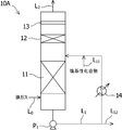
- FIG. 2 is a schematic diagram showing the configuration of the advanced desulfurization cooling tower in the first embodiment of the CO 2 recovery apparatus and recovery method according to the present invention.
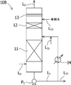
- FIG. 3 is a schematic diagram showing the configuration of the advanced desulfurization cooling tower in the second embodiment of the CO 2 recovery apparatus and recovery method according to the present invention.
- FIG. 4 is a schematic diagram showing the configuration of the advanced desulfurization cooling tower in the third embodiment of the CO 2 recovery apparatus and recovery method according to the present invention.
- FIG. 1 is a schematic diagram showing a configuration of a CO 2 recovery device according to a first embodiment of a CO 2 recovery device and a recovery method according to the present invention.
- FIG. 2 is a schematic diagram showing the configuration of the advanced desulfurization cooling tower in the first embodiment of the CO 2 recovery apparatus and recovery method according to the present invention.
- FIG. 5 is a schematic diagram showing the configuration of the advanced desulfurization cooling tower in the fourth embodiment of the CO 2 recovery apparatus and recovery method according to the present invention.
- FIG. 6 is a schematic diagram showing the configuration of the advanced desulfurization cooling tower in the fifth embodiment of the CO 2 recovery apparatus and recovery method according to the present invention.
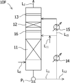
- FIG. 7 is a schematic diagram showing the configuration of the advanced desulfurization cooling tower in the sixth embodiment of the CO 2 recovery apparatus and recovery method according to the present invention.
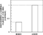
- FIG. 8 is a diagram showing the results of Example 1 for the CO 2 recovery apparatus and recovery method according to the present invention.
- FIG. 9 is a diagram showing the results of Example 2 for the CO 2 recovery apparatus and recovery method according to the present invention.
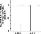
- FIG. 10 is a diagram showing the results of Example 3 for the CO 2 recovery apparatus and recovery method according to the present invention.
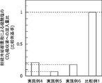
- FIG. 11 is a diagram showing the results of Examples 4 to 6 for the CO 2 recovery apparatus and recovery method according to the present invention.
- FIG. 1 A first embodiment of a CO 2 recovery apparatus according to the present invention will be described with reference to FIGS. 1 and 2.
- the CO 2 recovery apparatus absorbs and removes CO 2 in the exhaust gas with a CO 2 absorbing solution, and an advanced desulfurization cooling tower 10A for simultaneously performing advanced desulfurization and cooling on the exhaust gas.
- the exhaust gas includes carbon dioxide (CO 2 ) and sulfur oxide (SO 2 ) such as natural gas, process gas produced in chemical plants such as ammonia production, synthesis gas such as coal gasification gas, and combustion exhaust gas of fossil fuel. ) -Containing gas or the like can be used.
- the advanced desulfurization cooling tower 10A includes a line L 0 for supplying exhaust gas into the tower at the lower part of the tower, and a line L for discharging exhaust gas to the outside of the tower and supplying it to the CO 2 absorption tower 20 at the top of the tower. 2 at least.
- the line L 2 is provided with a blower B 1 for supplying exhaust gas to the CO 2 absorption tower 20.
- the advanced desulfurization cooling tower 10A includes an advanced desulfurization cooling filling unit 11, a finish filling unit 12, and a first demister 13.
- the circulating liquid stored in the bottom of the tower hereinafter also referred to as desulfurization cooling circulation liquid
- the circulation line L 1 for performing a cooling process in a single step means is provided.
- the advanced desulfurization cooling filling unit 11 is configured to directly mix the exhaust gas containing sulfur oxides and the desulfurization cooling circulating fluid containing a basic compound flowing down from above.
- the advanced desulfurization cooling filling unit 11 removes sulfur oxides in the exhaust gas by absorbing the sulfur oxides in the exhaust gas into the desulfurization cooling circulation liquid. Thereby, in the downstream of the advanced desulfurization cooling and filling unit 11, the concentration of sulfur oxide in the exhaust gas decreases.
- the finishing filling unit 12 is configured to collect the mist of the desulfurization cooling circulating liquid scattered from below in the tower and flow down to the advanced desulfurization cooling filling unit 11.
- the flowing-down liquid from the finish filling part 12 becomes a desulfurization cooling circulating liquid recovered along with the exhaust gas at the lower side.
- a filler for collecting sulfur oxides accompanying the exhaust gas is disposed inside the finish filling part 12. Examples of such fillers include plate-like regular fillers including folded plates and flat plates, and ring-like and saddle-like irregular fillers. Thereby, in the downstream of the finish filling part 12, the density
- the first demister 13 is located above the finish filling unit 12 and removes and collects mist of the desulfurization cooling circulating liquid accompanying the exhaust gas, and stores it at the bottom of the advanced desulfurization cooling tower 10A. Thereby, in the downstream of the 1st demister 13, the density
- One end of the circulation line L 1 is connected to the bottom of the advanced desulfurization cooling tower 10A (lower connection position), and the other end is connected to the advanced desulfurization cooling filling section 11 and the finish filling section 12 above the advanced desulfurization cooling tower 10A.
- the above-described connection position (upper connection position).
- the upper connection position is preferably closer to the advanced desulfurization cooling filling section 11 than the finish filling section 12. If it is such a position, the distance to the filler upper end of the advanced desulfurization cooling filling part 11 is short, and the accompanying amount to the exhaust gas by scattering of circulating fluid can be reduced.
- a cooler 14 for cooling the desulfurization cooling circulating liquid is provided on the circulation line L 1 .
- the circulation line L 1 is connected to the basic compound supply line L 11 in the downstream of the cooler 14 and is connected to the circulating liquid discharge line L 12 in the upstream of the cooler 14.
- Cooler 14 is a heat exchanger by cooling the desulfurization cooling the circulating fluid circulating in the circulation line L 1, the exhaust gas introduced into the high desulfurization cooling tower 10A from the line L 0 and cooled, the range of the predetermined temperature Within.
- the absorption efficiency of the CO 2 in CO 2 absorbing solution in the CO 2 absorber 20 can be prevented from being lowered.
- the basic compound supply line L 11 is connected to a supply tank (not shown) for storing the basic compound, and is configured to supply the basic compound in the supply tank to the desulfurization cooling circulating liquid in the circulation line L 1 .
- Such basic compounds include sodium compounds, calcium compounds or mixtures thereof.
- the sodium compound is preferably at least one selected from the group consisting of sodium hydroxide (NaOH), sodium carbonate (Na 2 CO 3 ), and sodium hydrogen carbonate (NaHCO 3 ).
- the calcium compound is preferably at least one selected from the group consisting of calcium hydroxide (Ca (OH) 2 ) and calcium carbonate (CaCO 3 ).
- the circulating fluid discharge line L 12 is used to remove a part of the desulfurized cooling circulating fluid that circulates in the circulating line L 1 in order to remove excess water condensed by the first cooler 14 by an on-off valve (not shown). It is configured to discharge.
- the on-off valve may be a manual valve, an automatic on-off valve, or a manual or automatic flow control valve. Thereby, the liquid level of the circulating fluid stored at the bottom of the advanced desulfurization cooling tower 10A can be maintained constant.
- the concentration of sulfur oxides in the exhaust gas to be introduced from the line L 2 in the CO 2 absorber 20, for example, as a 5ppm or less, sulfur oxides absorption of more equivalents of the basic compound to the desulfurization absorbing fluid can be supplied from the basic compound supply line L 11 so as to maintain the hydrogen ion index (pH) of the circulating liquid.
- high desulfurization cooling tower to reduce the number of parts required for the high desulfurization cooling process can be reduced in a simplified and manufacturing cost facilities in 10A, CO 2 absorption tower 20 of the CO 2 recovery apparatus It is possible to prevent the sulfur oxide, the basic compound, and the sulfate derived from the sulfur oxide and the basic compound from being mixed with the CO 2 absorbing solution.
- the number of steps required for advanced desulfurization cooling treatment is one
- the number of circulation of advanced desulfurization cooling circulating fluid required for treatment is one
- the number of coolers required for cooling can also be one.
- sodium hydroxide sodium hydroxide
- sodium sulfate Na 2 SO 4
- the mixing amount ratio of CO 2 absorption liquid can be reduced by about 60%.
- the CO 2 absorber 20 connected to the line L 2 for supplying the exhaust gas containing CO 2 at its lower tower to the CO 2 absorber 20, the exhaust gas to remove CO 2 in the top portion CO 2
- a line L 3 for discharging from the absorption tower 20 is provided.
- the CO 2 absorption tower 20 includes a CO 2 absorbing portion 21a in which the exhaust gas and the CO 2 absorbing liquid are in gas-liquid contact between the connection positions of the lines L 2 and L 3, and the exhaust gas after being in contact with the CO 2 absorbing liquid. And a washing part 21c positioned between the washing part 21b and the CO 2 absorption part 21a.
- the water receiver 21c is configured to allow gas to pass from below to above but not to allow liquid to pass from above to below. Furthermore, the water receiving portion 21c is accumulated liquid water receiving portion 21c, the line L 5 for supplying the CO 2 absorption tower 20 is provided from above the water washing section 21b. The line L 5 is provided with a pump P 5 for feeding liquid and a cooler 23 for cooling the liquid.
- CO in the bottom of the 2 absorber 20 CO 2 absorbent having absorbed CO 2 line L 4 for sending a portion to the regenerator 30 (rich absorbing liquid) is provided.
- the line L 4 is provided with a pump P 4 for feeding the CO 2 absorbing liquid and a heat exchanger 35 for heat exchange with the lean absorbing liquid described later in order from the CO 2 absorbing tower 20 side. It has been.
- the regeneration tower 30 includes a lower filling portion 31a for releasing CO 2 from the rich absorbent below the connection position with the line L 4 for supplying the rich absorbent, and a CO released from the connection position.
- cleaning 2 gas with the reflux water mentioned later and the absorption liquid receiving part 31c are provided under the lower filling part 31a.
- the absorbing liquid receiver 31c is configured to allow gas to pass from below to above but not to allow liquid to pass from above to below.
- the absorption liquid receiving portion 31c, the accumulated absorption liquid in the absorption liquid receiving portion 31c, a line L 7 for circulating and supplying to the regenerator 30 from the bottom of the absorption liquid receiving portion 31c is provided.
- the line L 7 is provided with a reboiler 32 that heats the absorbent to release CO 2 from the absorbent.
- the reboiler 32 is provided with a line L 6 for supplying saturated steam for heating to the reboiler 32.
- a line L 9 for discharging the CO 2 gas released from the rich absorbent from the regeneration tower 30 is provided at the top of the regeneration tower 30.
- the line L 9, a cooler 33 for cooling CO 2 gas, gas-liquid separator 34 for separating the condensed water and CO 2 gas generated by the cooling is provided.
- the gas-liquid separator 34 has a line L 9a for supplying the separated condensed water as reflux water to the upper side of the upper packed portion 31b in the regeneration tower 30, and a discharge for separating the separated CO 2 gas out of the system.
- line L 10 is provided.
- the line L 9a is provided with a pump P 9 for feeding the reflux water.
- the line L 8 includes a heat exchanger 35 that exchanges heat with the rich absorbent flowing through the line L 4 , a pump P 8 that feeds the lean absorbent, and a cooler 22 that cools the lean absorbent.
- the regeneration tower 30 can further optionally include a reclaimer (not shown) at the bottom of the tower.
- a reclaimer (not shown) at the bottom of the tower.
- the reclaimer after adding a basic compound to the lean absorbing liquid collected at the bottom of the tower, separates sulfate or sulfite from the lean absorbing liquid by heating with steam, and returns to the bottom of the regeneration tower 30. It is configured.
- the reclaimer is configured to discharge the separated sulfate or sulfite as sludge.
- the concentration of the sulfur oxide in the exhaust gas can be reduced in the advanced desulfurization cooling tower 10A. Therefore, the number of reclaiming by the reclaimer can be reduced, and the operation cost can be reduced.
- the exhaust gas containing CO 2 and sulfur oxide is supplied from the line L 0 to the advanced desulfurization cooling tower 10A, and the advanced desulfurization treatment and the cooling treatment are simultaneously performed as the advanced desulfurization cooling step.
- the advanced desulfurization cooling and filling section 11 directly mixes the flowing down liquid from the finish filling section 12 and the desulfurization cooling circulating liquid from the circulation line L 1, so that the sulfur oxide in the exhaust gas is removed. Remove.
- the desulfurization cooling circulating water accumulated at the bottom of the advanced desulfurization cooling tower 10A is cooled by the first cooler 14 via the circulation line L 1 by the pump P 1 and then supplied from the line L 11 to the advanced desulfurization cooling tower 10A. Recycle.
- the desulfurization cooling circulating liquid is supplied and circulated from the lower part to the upper part of the advanced desulfurization cooling tower 10A, and the falling liquid from the finish filling unit 12 and the desulfurization cooling circulating liquid from the circulation line are directly mixed.
- the temperature of the exhaust gas after cooling (cooling temperature) is preferably in the range of 30 ° C. or higher and 50 ° C. or lower, and more preferably in the range of 30 ° C. or higher and lower than 45 ° C. If the cooling temperature exceeds 50 ° C., for example, by absorption efficiency of CO 2 in the CO 2 absorber 20 is reduced, operating costs, etc. are increased. Further, when the cooling temperature is less than 30 ° C., the cost for cooling increases.
- blower exhaust gas from the top of high desulfurization tower 10A B 1 To the lower part of the CO 2 absorption tower 20 via the line L 2 .
- the CO 2 absorbent is an aqueous solution of an amine compound.
- the amine compound include monoethanolamine (C 2 H 7 NO), diethanolamine (C 4 H 11 NO 2 ), diisopropanolamine (C 6 H 15 NO). 2), can be used an alkanolamine such as methyldiethanolamine (C 5 H 13 NO 2) , triethanolamine (C 6 H 15 NO 3) .
- the exhaust gas from which CO 2 has been removed by the CO 2 absorption tower 20 is accompanied by water and an amine compound that are evaporated at a high temperature by an exothermic reaction due to CO 2 absorption. For this reason, it is made to contact with a washing
- the cleaning liquid containing water and the amine compound from the accumulated water receiving portion 21c after cooling by the cooler 23 through a line L 5 by a pump P 5 a part, the washing unit of the CO 2 absorber 20 with supplied above the 21b circulates utilized as the washing liquid, is added a portion of another for re-use as the absorbing solution as a surplus, the line L 8 supplies a lean absorption liquid through the line L 5a. Rich absorbent solution that has absorbed CO 2 is accumulated in the bottom of the CO 2 absorber 20 and heated by the heat exchanger 35 via a line L 4 by the pump P 4, supplied to the regenerator 30.
- the temperature is raised by exchanging heat with the high-temperature saturated vapor from L 6 to dissipate CO 2 in the rich absorbent.
- the saturated steam introduced into the reboiler 32 is condensed by heat exchange with the absorbing liquid to become saturated water, and is discharged from the reboiler 32.
- the lean absorbing solution from which CO 2 has been released accumulates at the bottom of the regeneration tower 30.
- the discharged CO 2 gas is cooled by the cooler 33 to condense the accompanying water vapor, and the gas-liquid separator 34 separates the CO 2 gas into condensed water. Separated CO 2 gas is discharged via a line L 10 and recovered as higher CO 2 gas purity, the condensed water is recycled as reflux water supplied to the regenerator 30 through a line L 9a by the pump P 9 .
- the lean absorbing liquid accumulated at the bottom of the regeneration tower 30 is introduced into the heat exchanger 35 via the line L 8 by the pump P 8 , cooled by exchanging heat with the rich absorbing liquid, and further cooled by the cooler 22. It is supplied to the CO 2 absorption tower 20 after being cooled and recycled as CO 2 absorbing solution for absorbing CO 2.
- the temperature of the CO 2 absorbent supplied to the CO 2 absorption tower 20 can be adjusted by the heat exchanger 35 and the cooler 22.
- FIG. 3 The CO 2 recovery apparatus shown in FIG. 3 is mainly different from the first embodiment in that an advanced desulfurization cooling tower 10B is provided instead of the advanced desulfurization cooling tower 10A. Further, the description of the same configuration as in FIGS. 1 and 2 is omitted.
- the advanced desulfurization cooling tower 10 ⁇ / b> B is connected to the dilution water supply line L 13 above the finish filling unit 12 and below the first demister 13.
- the dilution water supply line L 13 supplies dilution water from outside the system, that is, dilution water from the outside of the advanced desulfurization cooling tower 10 B, between the finish filling unit 12 and the first demister 13 in the tower.
- the circulating liquid recovered from the finish filling unit 12 is recovered by being accompanied by the diluted water supplied from the outside of the advanced desulfurization cooling tower supplied to the finish filling unit 12 and the exhaust gas below the finish filling unit 12. It becomes a liquid mixture with the liquid.
- the temperature of dilution water can be made into the range of 30 degreeC or more and 50 degrees C or less, for example.
- the same effect as that of the first embodiment is achieved, and the concentration of sulfate in the desulfurization cooling circulating liquid accompanying the exhaust gas is further reduced, and the CO 2 absorption tower is accompanied by the exhaust gas.
- the concentration of sulfate mixed in the CO 2 absorbing solution within 20 can be further reduced.
- sodium hydroxide used as the basic compound
- the sodium sulfate CO 2 absorbing solution that becomes the sulfate is compared with the case where the advanced desulfurization cooling is simply performed in one stage.
- the mixing ratio can be reduced by about 90%.
- FIG. 4 The CO 2 recovery apparatus shown in FIG. 4 is mainly different from the first embodiment in that an advanced desulfurization cooling tower 10C is provided instead of the advanced desulfurization cooling tower 10A. Also, high desulfurization tower 10C, in that it includes a branch circulation line L 15, mainly different and advanced desulfurization cooling tower 10A. Further, the description of the same configuration as in FIGS. 1 and 2 is omitted.
- the branch circulation line L 15 is configured to supply a part of the desulfurized and cooled circulating liquid of the circulation line L 1 to the upper part of the finish filling unit 12 and the lower part of the first demister 13 by an open / close valve (not shown).
- the on-off valve may be a manual valve, an automatic on-off valve, or a manual or automatic flow control valve.
- the branch circulation line L 15 limits the flow rate of the circulating fluid flowing into the circulation line L 1.
- the flow rate of the circulating fluid in the branch circulation line L 15 is made smaller than the flow rate of the circulating fluid in the circulation line L 1 .
- the flow rate ratio between the circulating fluid flow rate (ppm) in the branch circulation line L 15 and the circulating fluid flow rate (m 3 / h) in the circulation line L 1 is in the range of 1: 100 to 1: 3. be able to.
- the circulation is performed above the advanced desulfurization cooling filling portion 11 and the finishing filling portion 12 and below the first demister 13. The amount of liquid splash can be reduced. Therefore, it is possible to surely prevent sulfur oxides are mixed into the CO 2 absorbing solution.
- the branch circulation line L 15 further includes a second cooler 15.
- the second cooler 15 is a heat exchanger, reducing the temperature of the circulating fluid in the branch circulation line L 15.
- the second cooler 15 by condensing the moisture in the exhaust gas, than to decrease the concentration of sulfate circulating fluid in the branch circulation line L 15, reducing the concentration of sulfate salt to a quantity of the mist to spread can do.
- Basic compound supply line L 11 is connected to the circulation line L 1 at a circulation line L 1 and the branch circulation line L 15 and the connecting part flow later than.
- the basic compound is mixed into the branch circulation line L 15 , and the amount of mist of the circulating fluid accompanying the exhaust gas in the downstream of the first demister 13 can be reduced. Therefore, it is possible to prevent the contamination of sulfate in the CO 2 absorber 20 to the CO 2 absorbing solution. Thus, it is possible to prevent a decrease in CO 2 absorbent CO 2 absorbing solution.
- an effect similar to the first embodiment decreases more the concentration of sulfate desulfurization circulating cooling liquid entrained in the exhaust gas, CO 2 in the CO 2 absorber 20
- concentration of sulfate mixed in the absorbing solution can be further reduced.
- sodium hydroxide used as the basic compound
- the sodium sulfate CO 2 absorbing solution that becomes the sulfate is compared with the case where the advanced desulfurization cooling is simply performed in one stage.
- the mixing ratio can be reduced by about 75%.
- the CO 2 recovery apparatus of the present embodiment as compared with the CO 2 recovery apparatus of the first embodiment, in that it includes a high desulfurization tower 10D, further comprising a second demister 16, Mainly different.
- a high desulfurization tower 10D further comprising a second demister 16, Mainly different.
- the description of the same configuration as that in FIG. 2 is omitted.
- the second demister 16 is located above the advanced desulfurization cooling filling portion 11 and below the finish filling portion 12. More specifically, the second demister 16 is located above the upper connection positions of the high desulfurization tower 10D and circulation line L 1.
- the second demister 16 collects the circulating fluid that scatters upward from the advanced desulfurization cooling and filling portion 11 and reduces the concentration of sulfate in the circulating fluid in the upstream of the finish filling portion 12. Thereby, the concentration of sulfate in the exhaust gas discharged from the advanced desulfurization cooling tower 10 can be further reduced.
- the concentration of sulfate CO 2 absorbing solution in the CO 2 absorber 20 is compared with the case where the advanced desulfurization cooling is simply performed in one stage.
- the mixing ratio can be reduced by about 80%.
- the CO 2 recovery apparatus of the present embodiment as compared with the CO 2 recovery system of the second embodiment, in that it includes a high desulfurization tower 10E, further comprising a second demister 16, Mainly different. Further, the description of the same configuration as in FIG. 3 is omitted.
- the second demister 16 is located above the advanced desulfurization cooling filling portion 11 and below the finish filling portion 12. More specifically, the second demister 16 is located above the upper connection positions of the high desulfurization tower 10E and circulation line L 1.
- the second demister 16 collects the circulating fluid that scatters upward from the advanced desulfurization cooling and filling portion 11 and reduces the concentration of sulfate in the circulating fluid in the upstream of the finish filling portion 12. Thereby, the density
- the concentration of sulfate CO 2 absorbing solution in the CO 2 absorber 20 it is possible to with the same effects as the second embodiment, further reducing the concentration of sulfate CO 2 absorbing solution in the CO 2 absorber 20.
- the sodium sulfate CO 2 absorbing solution that becomes the sulfate is compared with the case where the advanced desulfurization cooling is simply performed in one stage.
- the mixing amount ratio can be reduced by 90% or more.
- FIG. 7 the CO 2 recovery apparatus of the present embodiment, as compared with the CO 2 recovery apparatus of the third embodiment, in that it includes a high desulfurization tower 10F, further comprising a second demister 16, Mainly different. Also, the description of the same configuration as in FIG. 4 is omitted.
- the second demister 16 is located above the advanced desulfurization cooling filling portion 11 and below the finish filling portion 12. More specifically, the second demister 16 is located above the upper connection positions of the high desulfurization tower 10F and circulation line L 1.
- the second demister 16 collects the circulating fluid that scatters upward from the advanced desulfurization cooling and filling portion 11 and reduces the concentration of sulfate in the circulating fluid in the upstream of the finish filling portion 12. Thereby, the density
- the concentration of sulfate CO 2 absorbing solution in the CO 2 absorber 20 is compared with the case where the advanced desulfurization cooling is simply performed in one stage.
- the mixing ratio can be reduced by 80% or more.
- the configuration of the CO 2 recovery device is exemplified.
- the present invention is not limited to this configuration.
- the CO 2 recovery device according to the present invention can further include a desulfurization device in the upstream of the advanced desulfurization cooling tower. By desulfurizing the desulfurization apparatus exhaust gas at the upstream side of the high desulfurization tower, the mixed amount of sulfate mixed in the CO 2 absorbing solution for CO 2 absorption tower 20 can be further reduced.
- the configuration and method including only the branch circulation line L 15 are exemplified.
- the present invention is not limited to this.
- the cooling temperature by the dilution water is the same as that in the second and fifth embodiments. can do.
- the cooling temperature with the dilution water can be set to the same temperature as the second and fifth embodiments.
- Example 1 the CO 2 recovery apparatus of the first embodiment was used. A regular filler was used as a filler in the finish filling section installed in the advanced desulfurization cooling tower of the CO 2 recovery unit. In addition, as Comparative Example 1, a CO 2 recovery apparatus including an advanced desulfurization cooling tower that performs advanced desulfurization cooling processing in one stage without a finish filling portion between the advanced desulfurization cooling filling portion and the demister was used.
- Example 1 and Comparative Example 1 the concentration of sodium sulfate as sulfate in the CO 2 absorbing solution was measured, respectively, and the concentration of sulfate in the CO 2 absorbing solution of Comparative Example 1 (The mixing amount ratio of sodium sulfate in Example 1 when the mixing amount) was 1 was evaluated. That was evaluated mixing amount ratio of the CO 2 absorbing solution by desulfurization circulating cooling fluid entrained in the exhaust gas to be introduced into the absorption tower.
- the exhaust gas flow rate introduced into the advanced desulfurization cooling tower was set to 200 m 3 / h.
- Sodium hydroxide was used as a basic compound to be introduced into the advanced desulfurization cooling tower, and the sulfur oxide concentration in the exhaust gas to be introduced into the CO 2 absorption tower was set to 5 ppm or less.
- the temperature in the advanced desulfurization cooling tower was cooled from 55 ° C. to 35 ° C. by the first cooler.
- Examples 1 and Comparative Example 1 using monoethanolamine as the CO 2 absorbing solution used in the CO 2 absorber, the circulation amount of the same city CO 2 absorbing solution, reclaimer of the regenerator did not run. The result of evaluation is shown in FIG.
- Example 2 The CO 2 recovery apparatus of the second embodiment was set as Example 2, and the concentration of sulfate in the CO 2 absorbent in the absorption tower was measured under the same conditions as in Example 1.
- the sulfate concentration (mixing amount) in the CO 2 absorbent of Comparative Example 1 was set to 1, the mixing amount ratio of the sulfate in Example 2 was evaluated.
- the inflow of dilution water from the dilution water supply line was 1: 100 in a ratio to the circulation amount of the circulation line. The evaluation results are shown in FIG.
- Example 3 The CO 2 recovery apparatus according to the third embodiment was set as Example 3, and the concentration of sulfate in the CO 2 absorbent in the absorption tower was measured under the same conditions as in Example 1.
- the sulfate mixing amount ratio in Example 3 was evaluated when the sulfate concentration (mixing amount) in the CO 2 absorbent of Comparative Example 1 was set to 1.
- the circulation amount to the branch circulation line in Example 3 was set to 1:20 in the ratio with respect to the circulation amount of a circulation line.
- the cooling temperature of the desulfurization cooling circulating liquid in a circulation line was 35 degreeC with the 2nd cooler. The evaluation results are shown in FIG.
- Example 1 The CO 2 recovery system of the fourth to sixth embodiments were respectively Examples 4-6. These not operate, and estimate the concentration of sulfate CO 2 absorbing solution in a CO 2 absorption tower as in Example 1 under the same conditions.
- Example 1 the amount of sulfate mixed in Examples 4 to 6 when the concentration (mixed amount) of sulfate in the CO 2 absorbent of Comparative Example 1 was set to 1. The ratio was examined.
- the operating conditions of Example 4 were the same as those of Example 1
- the operating conditions of Example 5 were the same as those of Example 2
- Example 6 were the same as those of Example 1.
- the mixing ratio of the sodium sulfate CO 2 absorbent is less than 0.1, and the mixing ratio of sodium sulfate is 1 It was confirmed that it could be reduced to less than / 10.
- the concentration of sulfate in the CO 2 absorbent can be reduced by 90% or more compared to Comparative Example 1.
- the CO 2 recovering apparatus and a recovery method of Example 5 also to simplify the structure of the device it was found to be reduced contamination of the CO 2 absorbing solution in the circulating liquid of the desulfurization cooling process.
- the mixing ratio of the sodium sulfate CO 2 absorbent is less than 0.2, and the mixing ratio of sodium sulfate is 1 It was confirmed that it could be reduced to less than / 5.
- the concentration of sulfate CO 2 absorbing solution can be reduced 80% or more.
- the CO 2 recovering apparatus and a recovery method of Example 6 also to simplify the structure of the device it was found to be reduced contamination of the CO 2 absorbing solution in the circulating liquid of the desulfurization cooling process.
- the structure of the device can be simplified.
- the amount of the desulfurization cooling treatment circulating liquid mixed into the CO 2 absorbing liquid can be reduced.
- Second demister 20 CO 2 absorption tower 21 a CO 2 absorption section 31 a Lower filling section 21 b Washing section 31 b Upper filling section 21 c Water receiving section 23, 33, 32 Cooler 30 Regeneration tower 31 c Absorbing liquid receiving section 32 Reboiler 34 Gas-liquid separator 35 Heat exchange vessel L 1 circulation line L 11 basic compound supply line L 12 circulating fluid discharge line L 13 dilution water supply line L 15 branched circulation line
Landscapes
- Chemical & Material Sciences (AREA)
- Engineering & Computer Science (AREA)
- Chemical Kinetics & Catalysis (AREA)
- Oil, Petroleum & Natural Gas (AREA)
- Analytical Chemistry (AREA)
- General Chemical & Material Sciences (AREA)
- Environmental & Geological Engineering (AREA)
- Health & Medical Sciences (AREA)
- Biomedical Technology (AREA)
- Organic Chemistry (AREA)
- Inorganic Chemistry (AREA)
- Life Sciences & Earth Sciences (AREA)
- Sustainable Development (AREA)
- Treating Waste Gases (AREA)
- Gas Separation By Absorption (AREA)
- Carbon And Carbon Compounds (AREA)
Abstract
Description
本発明に係るCO2回収装置の第1実施の形態について、図1及び図2を用いて説明する。図1に示すように、CO2回収装置は、排ガスに対して高度脱硫と冷却とを同時に実施するための高度脱硫冷却塔10Aと、排ガス中のCO2をCO2吸収液により吸収・除去するためのCO2吸収塔20と、CO2を回収すると共にCO2吸収液を再生する再生塔30とを備えている。排ガスとしては、天然ガス、アンモニア製造等の化学プラントにて製造されるプロセスガス、石炭ガス化ガス等の合成ガス、化石燃料の燃焼排ガス等の二酸化炭素(CO2)と硫黄酸化物(SO2)を含有するガス等を用いることができる。
続いて、本発明に係るCO2回収装置及び回収方法の第2実施の形態について、図3を参照して説明する。図3に示すCO2回収装置は、第1実施の形態と比較して、高度脱硫冷却塔10Aの代わりに高度脱硫冷却塔10Bを備える点において主に相違する。また、図1及び図2と同様の構成については、説明を省略する。
続いて、本発明に係るCO2回収装置及び回収方法の第3実施の形態について、図4を参照して説明する。図4に示すCO2回収装置は、第1実施の形態と比較して、高度脱硫冷却塔10Aの代わりに高度脱硫冷却塔10Cを備える点において、主に相違する。また、高度脱硫冷却塔10Cは、分岐循環ラインL15を備える点において、高度脱硫冷却塔10Aと主に相違する。また、図1及び図2と同様の構成については、説明を省略する。
続いて、本発明に係るCO2回収装置及び回収方法の第4実施の形態について、図5を参照して説明する。図5に示すように、本実施の形態のCO2回収装置は、第1実施の形態のCO2回収装置と比較して、第2デミスタ16を更に備える高度脱硫冷却塔10Dを備える点において、主に相違する。また、図2と同様の構成については、説明を省略する。
続いて、本発明に係るCO2回収装置及び回収方法の第5実施の形態について、図6を参照して説明する。図6に示すように、本実施の形態のCO2回収装置は、第2実施の形態のCO2回収装置と比較して、第2デミスタ16を更に備える高度脱硫冷却塔10Eを備える点において、主に相違する。また、図3と同様の構成については、説明を省略する。
続いて、本発明に係るCO2回収装置及び回収方法の第6実施の形態について、図7を参照して説明する。図7に示すように、本実施の形態のCO2回収装置は、第3実施の形態のCO2回収装置と比較して、第2デミスタ16を更に備える高度脱硫冷却塔10Fを備える点において、主に相違する。また、図4と同様の構成については、説明を省略する。
実施例1として、第1実施の形態のCO2回収装置を用いた。CO2回収装置の高度脱硫冷却塔に設置する仕上充填部には充填材として規則充填材を用いた。また、比較例1として、高度脱硫冷却充填部とデミスタとの間に仕上充填部を有さない、一段階で高度脱硫冷却処理を行う高度脱硫冷却塔を備えたCO2回収装置を用いた。実施例1と比較例1とのCO2吸収塔にて、それぞれCO2吸収液中の硫酸塩となる硫酸ナトリウムの濃度を測定し、比較例1のCO2吸収液中の硫酸塩の濃度(混入量)を1とした場合の、実施例1の硫酸ナトリウムの混入量比を評価した。すなわち、吸収塔に導入する排ガスに同伴する脱硫冷却循環液によるCO2吸収液への混入量比を評価した。実施例1及び比較例1では、高度脱硫冷却塔に導入する排ガス流量を200m3/hとした。高度脱硫冷却塔に導入する塩基性化合物として水酸化ナトリウムを用い、CO2吸収塔に導入する排ガス中の硫黄酸化物濃度を5ppm以下とした。また、第1冷却器により高度脱硫冷却塔内の温度を55℃から35℃まで冷却した。また、実施例1及び比較例1では、CO2吸収塔にて用いるCO2吸収液としてモノエタノールアミンを用い、CO2吸収液の循環量を同じとし、再生塔のリクレーマは稼働させなかった。評価の結果を図8に示す。
第2実施の形態のCO2回収装置を実施例2とし、実施例1と同条件にて吸収塔でのCO2吸収液中の硫酸塩の濃度を測定した。これを、実施例1と同様に、比較例1のCO2吸収液中の硫酸塩の濃度(混入量)を1とした場合の、実施例2の硫酸塩の混入量比を評価した。なお、実施例2にて、希釈水供給ラインからの希釈水の流入量は、循環ラインの循環量に対する比率で1:100とした。評価の結果を図9に示す。
第3実施の形態のCO2回収装置を実施例3とし、実施例1と同条件にて吸収塔でのCO2吸収液中の硫酸塩の濃度を測定した。これを、実施例1と同様に、比較例1のCO2吸収液中の硫酸塩の濃度(混入量)を1とした場合の、実施例3の硫酸塩の混入量比を評価した。なお、実施例3での分岐循環ラインへの循環量は、循環ラインの循環量に対する比率で1:20とした。また、第2冷却器により循環ライン内の脱硫冷却循環液の冷却温度は35℃とした。評価の結果を図10に示す。
第4~第6実施の形態のCO2回収装置を、それぞれ実施例4~6とした。これらを稼働させて、実施例1と同条件にてCO2吸収塔内のCO2吸収液中の硫酸塩の濃度を評価した。これらの結果について、それぞれ、実施例1と同様に、比較例1のCO2吸収液中の硫酸塩の濃度(混入量)を1とした場合の、実施例4~6の硫酸塩の混入量比を検討した。なお、実施例4の稼働条件は実施例1と同様とし、実施例5の稼働条件は実施例2と同様とし、実施例6の稼働条件は実施例1と同様とした。これらの結果を図11に示す。
11 高度脱硫冷却充填部
12 仕上充填部
13 第1デミスタ
14 第1冷却器
15 第2冷却器
16 第2デミスタ
20 CO2吸収塔
21a CO2吸収部
31a 下部充填部
21b 水洗部
31b 上部充填部
21c 水受部
23、33、32 冷却器
30 再生塔
31c 吸収液受部
32 リボイラ
34 気液分離器
35 熱交換器
L1 循環ライン
L11 塩基性化合物供給ライン
L12 循環液排出ライン
L13 希釈水供給ライン
L15 分岐循環ライン
Claims (8)
- 排ガス中の硫黄酸化物を除去すると共に、前記排ガス温度を下げる高度脱硫冷却塔と、
前記排ガス中のCO2をCO2吸収液に接触させて除去するCO2吸収塔と、
前記CO2吸収液からCO2を放散してCO2を回収すると共に前記CO2吸収液を再生し、前記再生したCO2吸収液を前記CO2吸収塔に送液する再生塔と
を備え、
前記高度脱硫冷却塔が、前記脱硫と前記冷却とを行うための脱硫冷却循環液を高度脱硫冷却塔の下部から上部へ供給して循環する循環ラインと、前記循環ラインと前記冷却塔の上部との接続位置よりも上方に位置する仕上充填部と、前記循環液を冷却する第1冷却器とを備え、前記仕上充填部からの流下液と前記循環ラインからの循環液とを直接混合する、
CO2回収装置。 - 前記高度脱硫冷却塔が、前記仕上充填部の上方に位置する第1デミスタを含んでなる請求項1に記載のCO2回収装置。
- 前記高度脱硫冷却塔が、前記仕上充填部の上方に位置して系外からの水を供給する希釈水供給ラインを含んでなる請求項1又は2に記載のCO2回収装置。
- 前記高度脱硫冷却塔が、前記循環ラインの前記第1冷却器の後流にて連結し、前記循環液の一部を前記仕上充填部の上方且つ前記第1デミスタの下方に供給する分岐循環ラインを更に備え、
前記分岐循環ラインが、前記循環液の一部を冷却する第2冷却器を備える請求項2に記載のCO2回収装置。 - 前記高度脱硫冷却塔が、前記循環ラインの上部の前記循環供給位置と前記仕上充填部との間に位置する第2デミスタを含んでなる請求項1~4のいずれか一項に記載のCO2回収装置。
- 前記循環ラインが、前記第1冷却器又は分岐循環ラインとの連結部の後流にて連結する塩基性化合物供給ラインを更に備える請求項3~5のいずれか一項に記載のCO2回収装置。
- 前記循環ラインが、前記第1冷却器の前流にて連結する余剰液排出ラインを更に備える請求項1~6のいずれか一項に記載のCO2回収装置。
- 前記請求項1~7のいずれか一項に記載のCO2回収装置を用いたCO2回収方法であって、
排ガス中の硫黄酸化物を除去すると共に、前記排ガス温度を下げる高度脱硫冷却工程と、
前記排ガス中のCO2をCO2吸収液に接触させて除去するCO2吸収工程と、
前記CO2吸収液からCO2を放散して、CO2を回収すると共に前記CO2吸収液を再生し、前記再生したCO2吸収液を前記CO2吸収塔に送液して再利用する再生塔と
を含み、
前記高度脱硫冷却工程が、前記脱硫と前記冷却とを行うための脱硫冷却循環液を高度脱硫冷却塔の下部から上部へ供給して循環する循環工程と、前記循環ラインと前記冷却塔の上部との接続位置よりも上方に位置する仕上充填部からの流下液と前記循環ラインからの循環液とを直接混合する混合工程と更に含む、CO2回収方法。
Priority Applications (4)
| Application Number | Priority Date | Filing Date | Title |
|---|---|---|---|
| CA3008778A CA3008778C (en) | 2016-01-14 | 2016-12-12 | Co2 recovery device and recovery method |
| EP16885081.6A EP3403713B1 (en) | 2016-01-14 | 2016-12-12 | Co2 recovery device and recovery method |
| US16/068,447 US10953361B2 (en) | 2016-01-14 | 2016-12-12 | CO2 recovery device and recovery method |
| AU2016386569A AU2016386569B2 (en) | 2016-01-14 | 2016-12-12 | CO2 recovery device and recovery method |
Applications Claiming Priority (2)
| Application Number | Priority Date | Filing Date | Title |
|---|---|---|---|
| JP2016-005486 | 2016-01-14 | ||
| JP2016005486A JP6639918B2 (ja) | 2016-01-14 | 2016-01-14 | Co2回収装置及び回収方法 |
Publications (1)
| Publication Number | Publication Date |
|---|---|
| WO2017122478A1 true WO2017122478A1 (ja) | 2017-07-20 |
Family
ID=59311205
Family Applications (1)
| Application Number | Title | Priority Date | Filing Date |
|---|---|---|---|
| PCT/JP2016/086881 Ceased WO2017122478A1 (ja) | 2016-01-14 | 2016-12-12 | Co2回収装置及び回収方法 |
Country Status (6)
| Country | Link |
|---|---|
| US (1) | US10953361B2 (ja) |
| EP (1) | EP3403713B1 (ja) |
| JP (1) | JP6639918B2 (ja) |
| AU (1) | AU2016386569B2 (ja) |
| CA (1) | CA3008778C (ja) |
| WO (1) | WO2017122478A1 (ja) |
Cited By (3)
| Publication number | Priority date | Publication date | Assignee | Title |
|---|---|---|---|---|
| CN110975546A (zh) * | 2019-12-26 | 2020-04-10 | 江苏新世纪江南环保股份有限公司 | 一种改进的氨法脱硫控制吸收过程气溶胶产生的方法 |
| JP6788162B1 (ja) * | 2019-12-10 | 2020-11-25 | 健司 反町 | 二酸化炭素の固定装置 |
| US11305228B2 (en) | 2019-08-29 | 2022-04-19 | Kenji SORIMACHI | Method for fixing carbon dioxide, method for producing fixed carbon dioxide, and fixed carbon dioxide production apparatus |
Citations (5)
| Publication number | Priority date | Publication date | Assignee | Title |
|---|---|---|---|---|
| JP2005087828A (ja) * | 2003-09-16 | 2005-04-07 | Kansai Electric Power Co Inc:The | 脱硫脱炭酸方法及びその装置 |
| JP2009530073A (ja) * | 2006-03-16 | 2009-08-27 | ビーエーエスエフ ソシエタス・ヨーロピア | 二相の接点が熱発生を随伴している二相を接触させる方法 |
| JP2013512088A (ja) * | 2009-11-24 | 2013-04-11 | アルストム テクノロジー リミテッド | Co2吸収における進化した中間冷却及び再循環 |
| WO2013144864A1 (en) | 2012-03-30 | 2013-10-03 | Alstom Technology Ltd | Condenser and method for heat recovery and cooling |
| WO2013144889A1 (en) | 2012-03-30 | 2013-10-03 | Alstom Technology Ltd | Condenser and method for cleaning flue gases |
Family Cites Families (9)
| Publication number | Priority date | Publication date | Assignee | Title |
|---|---|---|---|---|
| JP5351728B2 (ja) * | 2009-12-03 | 2013-11-27 | 三菱重工業株式会社 | Co2回収装置およびco2回収方法 |
| JP5755047B2 (ja) | 2011-06-22 | 2015-07-29 | 三菱重工業株式会社 | 排ガス処理システム及び排ガス処理方法 |
| EP2786793B1 (en) | 2011-12-01 | 2017-10-18 | Kabushiki Kaisha Toshiba, Inc. | Carbon dioxide recovery device, carbon dioxide recovery method, and amine compound recovery method |
| JP6125160B2 (ja) | 2012-06-15 | 2017-05-10 | 三菱重工業株式会社 | 排ガス処理システム |
| US8486357B1 (en) * | 2012-09-12 | 2013-07-16 | Mitsubishi Heavy Industries, Ltd. | Desulfurization apparatus and method of using condensed water produced therein |
| US9233337B2 (en) | 2012-09-20 | 2016-01-12 | Mitsubishi Heavy Industries, Ltd. | CO2 recovery device |
| US8545782B1 (en) | 2012-10-16 | 2013-10-01 | Mitsubishi Heavy Industries, Ltd. | CO2 recovery apparatus and CO2 recovery method |
| JP6225572B2 (ja) | 2013-09-05 | 2017-11-08 | 株式会社Ihi | 二酸化炭素の回収方法及び回収装置 |
| JP6248813B2 (ja) | 2014-05-28 | 2017-12-20 | 株式会社Ihi | 二酸化炭素の回収方法及び回収装置 |
-
2016
- 2016-01-14 JP JP2016005486A patent/JP6639918B2/ja active Active
- 2016-12-12 US US16/068,447 patent/US10953361B2/en active Active
- 2016-12-12 WO PCT/JP2016/086881 patent/WO2017122478A1/ja not_active Ceased
- 2016-12-12 EP EP16885081.6A patent/EP3403713B1/en active Active
- 2016-12-12 AU AU2016386569A patent/AU2016386569B2/en active Active
- 2016-12-12 CA CA3008778A patent/CA3008778C/en active Active
Patent Citations (6)
| Publication number | Priority date | Publication date | Assignee | Title |
|---|---|---|---|---|
| JP2005087828A (ja) * | 2003-09-16 | 2005-04-07 | Kansai Electric Power Co Inc:The | 脱硫脱炭酸方法及びその装置 |
| JP4216152B2 (ja) | 2003-09-16 | 2009-01-28 | 関西電力株式会社 | 脱硫脱炭酸方法及びその装置 |
| JP2009530073A (ja) * | 2006-03-16 | 2009-08-27 | ビーエーエスエフ ソシエタス・ヨーロピア | 二相の接点が熱発生を随伴している二相を接触させる方法 |
| JP2013512088A (ja) * | 2009-11-24 | 2013-04-11 | アルストム テクノロジー リミテッド | Co2吸収における進化した中間冷却及び再循環 |
| WO2013144864A1 (en) | 2012-03-30 | 2013-10-03 | Alstom Technology Ltd | Condenser and method for heat recovery and cooling |
| WO2013144889A1 (en) | 2012-03-30 | 2013-10-03 | Alstom Technology Ltd | Condenser and method for cleaning flue gases |
Non-Patent Citations (1)
| Title |
|---|
| See also references of EP3403713A4 |
Cited By (4)
| Publication number | Priority date | Publication date | Assignee | Title |
|---|---|---|---|---|
| US11305228B2 (en) | 2019-08-29 | 2022-04-19 | Kenji SORIMACHI | Method for fixing carbon dioxide, method for producing fixed carbon dioxide, and fixed carbon dioxide production apparatus |
| JP6788162B1 (ja) * | 2019-12-10 | 2020-11-25 | 健司 反町 | 二酸化炭素の固定装置 |
| CN110975546A (zh) * | 2019-12-26 | 2020-04-10 | 江苏新世纪江南环保股份有限公司 | 一种改进的氨法脱硫控制吸收过程气溶胶产生的方法 |
| CN110975546B (zh) * | 2019-12-26 | 2021-08-17 | 江苏新世纪江南环保股份有限公司 | 一种改进的氨法脱硫控制吸收过程气溶胶产生的方法 |
Also Published As
| Publication number | Publication date |
|---|---|
| JP6639918B2 (ja) | 2020-02-05 |
| EP3403713A1 (en) | 2018-11-21 |
| AU2016386569B2 (en) | 2019-07-25 |
| CA3008778C (en) | 2020-06-30 |
| AU2016386569A1 (en) | 2018-07-12 |
| CA3008778A1 (en) | 2017-07-20 |
| US20190022575A1 (en) | 2019-01-24 |
| JP2017124373A (ja) | 2017-07-20 |
| EP3403713B1 (en) | 2023-05-24 |
| US10953361B2 (en) | 2021-03-23 |
| EP3403713A4 (en) | 2019-10-09 |
Similar Documents
| Publication | Publication Date | Title |
|---|---|---|
| RU2558361C2 (ru) | Способ водной промывки и система для способа улавливания диоксида углерода | |
| AU2012212630B2 (en) | Gas treatment process and system | |
| JP5722031B2 (ja) | ガス流からガス成分を回収するための方法及び吸収剤組成物 | |
| JP5507584B2 (ja) | アミン放出物制御のための方法およびプラント | |
| JP5968159B2 (ja) | Co2回収装置およびco2回収方法 | |
| AU2013317025B2 (en) | Desulfurization device and method for using condensate water generated thereby | |
| CA2840755C (en) | Chilled ammonia based co2 capture system with ammonia recovery and processes of use | |
| CN111729483A (zh) | 一种二氧化碳捕集系统及方法 | |
| JP6598688B2 (ja) | 酸性ガス回収システム及びそれに用いるリクレーミング装置 | |
| CN103328074B (zh) | 用于清洁气体流的方法和系统 | |
| JP6639918B2 (ja) | Co2回収装置及び回収方法 | |
| WO2019087901A1 (ja) | ガス処理装置及びガス処理方法、co2回収装置及びco2回収方法 |
Legal Events
| Date | Code | Title | Description |
|---|---|---|---|
| 121 | Ep: the epo has been informed by wipo that ep was designated in this application |
Ref document number: 16885081 Country of ref document: EP Kind code of ref document: A1 |
|
| ENP | Entry into the national phase |
Ref document number: 3008778 Country of ref document: CA |
|
| ENP | Entry into the national phase |
Ref document number: 2016386569 Country of ref document: AU Date of ref document: 20161212 Kind code of ref document: A |
|
| NENP | Non-entry into the national phase |
Ref country code: DE |
|
| WWE | Wipo information: entry into national phase |
Ref document number: 2016885081 Country of ref document: EP |
|
| ENP | Entry into the national phase |
Ref document number: 2016885081 Country of ref document: EP Effective date: 20180814 |