WO2017126137A1 - コアシェル構造型ナノシート - Google Patents
コアシェル構造型ナノシート Download PDFInfo
- Publication number
- WO2017126137A1 WO2017126137A1 PCT/JP2016/067048 JP2016067048W WO2017126137A1 WO 2017126137 A1 WO2017126137 A1 WO 2017126137A1 JP 2016067048 W JP2016067048 W JP 2016067048W WO 2017126137 A1 WO2017126137 A1 WO 2017126137A1
- Authority
- WO
- WIPO (PCT)
- Prior art keywords
- nanosheet
- platinum
- core
- metal
- catalyst
- Prior art date
- Legal status (The legal status is an assumption and is not a legal conclusion. Google has not performed a legal analysis and makes no representation as to the accuracy of the status listed.)
- Ceased
Links
Images





Classifications
-
- H—ELECTRICITY
- H01—ELECTRIC ELEMENTS
- H01M—PROCESSES OR MEANS, e.g. BATTERIES, FOR THE DIRECT CONVERSION OF CHEMICAL ENERGY INTO ELECTRICAL ENERGY
- H01M4/00—Electrodes
- H01M4/86—Inert electrodes with catalytic activity, e.g. for fuel cells
- H01M4/90—Selection of catalytic material
- H01M4/92—Metals of platinum group
- H01M4/925—Metals of platinum group supported on carriers, e.g. powder carriers
-
- B—PERFORMING OPERATIONS; TRANSPORTING
- B01—PHYSICAL OR CHEMICAL PROCESSES OR APPARATUS IN GENERAL
- B01J—CHEMICAL OR PHYSICAL PROCESSES, e.g. CATALYSIS OR COLLOID CHEMISTRY; THEIR RELEVANT APPARATUS
- B01J23/00—Catalysts comprising metals or metal oxides or hydroxides, not provided for in group B01J21/00
- B01J23/38—Catalysts comprising metals or metal oxides or hydroxides, not provided for in group B01J21/00 of noble metals
- B01J23/40—Catalysts comprising metals or metal oxides or hydroxides, not provided for in group B01J21/00 of noble metals of the platinum group metals
- B01J23/46—Ruthenium, rhodium, osmium or iridium
-
- H—ELECTRICITY
- H01—ELECTRIC ELEMENTS
- H01M—PROCESSES OR MEANS, e.g. BATTERIES, FOR THE DIRECT CONVERSION OF CHEMICAL ENERGY INTO ELECTRICAL ENERGY
- H01M4/00—Electrodes
- H01M4/86—Inert electrodes with catalytic activity, e.g. for fuel cells
-
- H—ELECTRICITY
- H01—ELECTRIC ELEMENTS
- H01M—PROCESSES OR MEANS, e.g. BATTERIES, FOR THE DIRECT CONVERSION OF CHEMICAL ENERGY INTO ELECTRICAL ENERGY
- H01M4/00—Electrodes
- H01M4/86—Inert electrodes with catalytic activity, e.g. for fuel cells
- H01M4/8647—Inert electrodes with catalytic activity, e.g. for fuel cells consisting of more than one material, e.g. consisting of composites
- H01M4/8657—Inert electrodes with catalytic activity, e.g. for fuel cells consisting of more than one material, e.g. consisting of composites layered
-
- H—ELECTRICITY
- H01—ELECTRIC ELEMENTS
- H01M—PROCESSES OR MEANS, e.g. BATTERIES, FOR THE DIRECT CONVERSION OF CHEMICAL ENERGY INTO ELECTRICAL ENERGY
- H01M4/00—Electrodes
- H01M4/86—Inert electrodes with catalytic activity, e.g. for fuel cells
- H01M4/88—Processes of manufacture
- H01M4/8825—Methods for deposition of the catalytic active composition
- H01M4/8846—Impregnation
- H01M4/885—Impregnation followed by reduction of the catalyst salt precursor
-
- H—ELECTRICITY
- H01—ELECTRIC ELEMENTS
- H01M—PROCESSES OR MEANS, e.g. BATTERIES, FOR THE DIRECT CONVERSION OF CHEMICAL ENERGY INTO ELECTRICAL ENERGY
- H01M4/00—Electrodes
- H01M4/86—Inert electrodes with catalytic activity, e.g. for fuel cells
- H01M4/90—Selection of catalytic material
- H01M4/92—Metals of platinum group
-
- H—ELECTRICITY
- H01—ELECTRIC ELEMENTS
- H01M—PROCESSES OR MEANS, e.g. BATTERIES, FOR THE DIRECT CONVERSION OF CHEMICAL ENERGY INTO ELECTRICAL ENERGY
- H01M4/00—Electrodes
- H01M4/86—Inert electrodes with catalytic activity, e.g. for fuel cells
- H01M4/90—Selection of catalytic material
- H01M4/92—Metals of platinum group
- H01M4/925—Metals of platinum group supported on carriers, e.g. powder carriers
- H01M4/926—Metals of platinum group supported on carriers, e.g. powder carriers on carbon or graphite
-
- B—PERFORMING OPERATIONS; TRANSPORTING
- B01—PHYSICAL OR CHEMICAL PROCESSES OR APPARATUS IN GENERAL
- B01J—CHEMICAL OR PHYSICAL PROCESSES, e.g. CATALYSIS OR COLLOID CHEMISTRY; THEIR RELEVANT APPARATUS
- B01J21/00—Catalysts comprising the elements, oxides, or hydroxides of magnesium, boron, aluminium, carbon, silicon, titanium, zirconium, or hafnium
- B01J21/18—Carbon
-
- B—PERFORMING OPERATIONS; TRANSPORTING
- B01—PHYSICAL OR CHEMICAL PROCESSES OR APPARATUS IN GENERAL
- B01J—CHEMICAL OR PHYSICAL PROCESSES, e.g. CATALYSIS OR COLLOID CHEMISTRY; THEIR RELEVANT APPARATUS
- B01J2235/00—Indexing scheme associated with group B01J35/00, related to the analysis techniques used to determine the catalysts form or properties
- B01J2235/30—Scanning electron microscopy; Transmission electron microscopy
-
- B—PERFORMING OPERATIONS; TRANSPORTING
- B01—PHYSICAL OR CHEMICAL PROCESSES OR APPARATUS IN GENERAL
- B01J—CHEMICAL OR PHYSICAL PROCESSES, e.g. CATALYSIS OR COLLOID CHEMISTRY; THEIR RELEVANT APPARATUS
- B01J35/00—Catalysts, in general, characterised by their form or physical properties
- B01J35/30—Catalysts, in general, characterised by their form or physical properties characterised by their physical properties
-
- H—ELECTRICITY
- H01—ELECTRIC ELEMENTS
- H01M—PROCESSES OR MEANS, e.g. BATTERIES, FOR THE DIRECT CONVERSION OF CHEMICAL ENERGY INTO ELECTRICAL ENERGY
- H01M4/00—Electrodes
- H01M4/86—Inert electrodes with catalytic activity, e.g. for fuel cells
- H01M2004/8678—Inert electrodes with catalytic activity, e.g. for fuel cells characterised by the polarity
- H01M2004/8689—Positive electrodes
-
- H—ELECTRICITY
- H01—ELECTRIC ELEMENTS
- H01M—PROCESSES OR MEANS, e.g. BATTERIES, FOR THE DIRECT CONVERSION OF CHEMICAL ENERGY INTO ELECTRICAL ENERGY
- H01M8/00—Fuel cells; Manufacture thereof
- H01M8/10—Fuel cells with solid electrolytes
- H01M2008/1095—Fuel cells with polymeric electrolytes
-
- H—ELECTRICITY
- H01—ELECTRIC ELEMENTS
- H01M—PROCESSES OR MEANS, e.g. BATTERIES, FOR THE DIRECT CONVERSION OF CHEMICAL ENERGY INTO ELECTRICAL ENERGY
- H01M8/00—Fuel cells; Manufacture thereof
- H01M8/10—Fuel cells with solid electrolytes
-
- Y—GENERAL TAGGING OF NEW TECHNOLOGICAL DEVELOPMENTS; GENERAL TAGGING OF CROSS-SECTIONAL TECHNOLOGIES SPANNING OVER SEVERAL SECTIONS OF THE IPC; TECHNICAL SUBJECTS COVERED BY FORMER USPC CROSS-REFERENCE ART COLLECTIONS [XRACs] AND DIGESTS
- Y02—TECHNOLOGIES OR APPLICATIONS FOR MITIGATION OR ADAPTATION AGAINST CLIMATE CHANGE
- Y02E—REDUCTION OF GREENHOUSE GAS [GHG] EMISSIONS, RELATED TO ENERGY GENERATION, TRANSMISSION OR DISTRIBUTION
- Y02E60/00—Enabling technologies; Technologies with a potential or indirect contribution to GHG emissions mitigation
- Y02E60/30—Hydrogen technology
- Y02E60/50—Fuel cells
Definitions
- the present invention relates to a core-shell structured nanosheet. More specifically, the present invention relates to a core-shell structure type nanosheet having a metal nanosheet as a core and platinum as a shell. This can be applied to an electrode catalyst such as a polymer electrolyte fuel cell.
- ⁇ High-performance electrode catalysts are required for full-scale spread of polymer electrolyte fuel cells.
- a catalyst having Pt nanoparticles supported on carbon (referred to as a Pt nanoparticle / C catalyst) is known as one that shows current practical catalyst performance.
- Pt nanoparticles / C catalysts use platinum, which is expensive and has a small amount of resources, as a nanoparticle, reduction of the amount of platinum used is considered as an issue to be studied.
- a catalyst in which PtCo alloy nanoparticles are supported on carbon referred to as PtCo nanoparticles / C catalyst
- PtCo nanoparticles / C catalyst a catalyst in which PtCo alloy nanoparticles are supported on carbon
- An electrode catalyst in which a core-shell structure in which a Pt atom layer is provided on the surface of Au nanoparticles is supported on carbon can reduce the amount of Pt and further increase the surface area. Therefore, it is said that the catalytic activity per mass of Pt can be improved and the amount of Pt can be reduced. Furthermore, since the electrode catalyst has Au nanoparticles as a core, there is also an advantage that it is stable.
- a copper monoatomic layer deposition method (Cu-UPD method) by an electrochemical reaction is applied as a means for providing a Pt atomic layer on the surface of Au nanoparticles.
- Non-Patent Document 1 a core-shell catalyst in which a Pt atomic layer is provided in a monolayer of 1 to 3 on the surface of Ru nanoparticles has an oxygen reduction reaction activity that is about 3 to 5 times higher than that of a Pt / C catalyst.
- the electrocatalyst proposed in Patent Document 1 and Non-Patent Document 1 employs Au or Ru nanoparticles instead of Pt nanoparticles, and a Pt atomic layer is provided on the surface of the nanoparticles.
- Pt atoms are not wasted. Therefore, there is an advantage that the catalytic activity per mass of Pt can be improved and the amount of expensive Pt can be reduced.
- this electrode catalyst employs expensive Au or Ru nanoparticles as the core particles, similar to the Pt nanoparticles.
- the electrode catalyst using the nanoparticles may aggregate and / or grow during the operation of the fuel cell, and the catalyst performance may be deteriorated.
- the present inventor has developed a novel core-shell structure type Developed nanosheet.
- An object of the present invention is to provide a novel core-shell structured nanosheet.
- the core-shell structured nanosheet according to the present invention includes a metal nanosheet and a platinum atomic layer provided on the surface of the metal nanosheet.
- the platinum atomic layer is provided on the surface of the metal nanosheet, the following can be performed. (1) Unlike the case of using conventional nanoparticles, it is possible to reduce the number of useless atoms that cannot contribute to the reaction as much as possible. (2) The platinum atomic layer is provided on the surface of the metal nanosheet. Therefore, for example, when used as a catalyst, the catalytic activity per mass of platinum can be improved. Furthermore, it is possible to reduce expensive platinum. (3) Since it has a nanosheet structure, unlike the case where conventional nanoparticles are used, aggregation of nanoparticles and / or particle growth is unlikely to occur. Therefore, for example, when used as a catalyst, it is possible to suppress a decrease in the catalyst performance.
- the platinum atomic layer may be provided on the entire surface of the metal nanosheet. According to the present invention, since the platinum atomic layer is provided on the entire surface of the metal nanosheet, for example, when used as a catalyst, the low active portion without the platinum atomic layer can be reduced as much as possible.
- the core-shell structure type nanosheet according to the present invention it is preferably used as an electrode catalyst.
- it since it is used as an electrode catalyst for a fuel cell or the like, it can further improve the catalytic activity of an electrode catalyst (for example, an electrode catalyst for a polymer electrolyte fuel cell), and agglomeration and particle growth like a nanoparticle catalyst. Based on this, it is possible to achieve a reduction in catalyst performance.
- the electrode catalyst can be used as a cathode catalyst or an anode catalyst.
- the oxygen reduction activity can be further increased, and a decrease in catalyst performance can be suppressed.
- carbon monoxide poisoning resistance (CO poisoning resistance) and durability can be further improved.
- an unprecedented novel core-shell structure type nanosheet could be provided.
- the core-shell structure type nanosheet according to the present invention the following can be achieved. (1) Unlike the case of using conventional nanoparticles, it is possible to reduce the number of useless atoms that cannot contribute to the reaction as much as possible. (2) For example, when used as a catalyst, the catalytic activity per mass of platinum can be improved. Furthermore, the amount of expensive platinum used can be reduced. (3) Since aggregation of nanoparticles and / or particle growth is unlikely to occur, for example, when used as a catalyst, a decrease in the catalyst performance can be suppressed.
- FIG. 1 It is a schematic diagram explaining the core-shell structure type
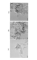
- A is a transmission electron microscope image of an electrode catalyst in which a metal ruthenium nanosheet is supported on carbon.
- (B) is a transmission electron microscope image of an electrode catalyst in which a core-shell structure type nanosheet comprising a metal ruthenium nanosheet core / platinum shell (UPD-platinum substitution method: twice) is supported on carbon.
- (C) is a transmission electron microscope image of an electrode catalyst in which a core-shell structure type nanosheet comprising a metal ruthenium nanosheet core / platinum shell (UPD-platinum substitution method: 4 times) is supported on carbon.
- the number of repetitions of the formation step of the platinum atomic layer by the UPD-platinum substitution method (from 1 to 5 times), and the electrocatalyst in which the core-shell structure type nanosheet composed of the metal ruthenium nanosheet core / platinum shell obtained on each is supported on carbon
- It is a graph which shows the relationship with an electrochemical active surface area (ECSA).
- (A) is a CO stripping voltammogram in which the platinum catalyst is assigned to the electrocatalyst carrying Pt nanoparticles on carbon by the amount of platinum.
- (B) is a CO stripping voltammogram in which platinum ruthenium nanoparticles are supported on carbon and assigned by the amount of PtRu.
- (C) is a CO stripping voltammogram in which an electrocatalyst having a core-shell structured nanosheet composed of a metal ruthenium nanosheet core / platinum shell (UPD-platinum substitution method: 2 times) supported on carbon is assigned by the amount of PtRu.
- (A) is a linear sweep voltammogram in hydrogen assigned to the amount of PtRu for an electrode catalyst in which a core-shell structured nanosheet consisting of a metal ruthenium nanosheet core / platinum shell (UPD-platinum substitution method: 2 times) is supported on carbon.
- (B) is a stripping voltammogram in hydrogen assigned to the amount of PtRu for an electrode catalyst in which platinum ruthenium nanoparticles are supported on carbon.
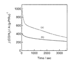
- (A) is a chronoampere in 300 ppm CO / H 2 in 300 ppm CO / H 2 with an amount of PtRu assigned to an electrode catalyst in which a core-shell structured nanosheet consisting of metal ruthenium nanosheet core / platinum shell (UPD-platinum substitution method: 2 times) is supported on carbon Program.
- (B) is a chronoamperogram in 300 ppm CO / H 2 assigned by the amount of PtRu for an electrode catalyst in which platinum ruthenium nanoparticles are supported on carbon.
- (A) shows hydrogen oxidation in 300 ppm CO / H 2 with an amount of PtRu assigned to an electrode catalyst in which a core-shell structured nanosheet consisting of a metal ruthenium nanosheet core / platinum shell (UPD-platinum substitution method: 2 times) is supported on carbon. Reaction activity and hydrogen oxidation reaction activity after an endurance test after 1000 cycles (0.05 to 0.4 V vs. RHE (each held for 3 seconds)).
- (B) shows an electrode catalyst in which platinum ruthenium nanoparticles are supported on carbon, hydrogen oxidation activity in 300 ppm CO / H 2 assigned by the amount of PtRu, and durability test after 1000 cycles (0.05 to 0.4 V vs. RHE).
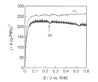
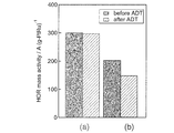
- (A) is a graph of the ORR activity assigned by the amount of platinum for an electrode catalyst in which Pt nanoparticles are supported on carbon.
- (B) is a graph of ORR activity assigned by the amount of platinum in an electrode catalyst in which a core-shell structured nanosheet consisting of a metal ruthenium nanosheet core / platinum shell (UPD-platinum substitution method: 4 times) is supported on carbon.
- (C) is a graph of ORR activity assigned by the amount of platinum in an electrode catalyst in which a core-shell structured nanosheet consisting of a metal ruthenium nanosheet core / platinum shell (UPD-platinum substitution method: 5 times) is supported on carbon.
- (A) is a plot of ECSA reduction rate when the electrocatalyst having Pt nanoparticles supported on carbon is normalized by initial ECSA.
- (B) is a plot of ECSA reduction rate when normalized with initial ECSA in an electrode catalyst in which a core-shell structured nanosheet consisting of metal ruthenium nanosheet core / platinum shell (UPD-platinum substitution method: 4 times) is supported on carbon. is there.
- (C) is a plot of ECSA reduction rate when normalized with initial ECSA in an electrode catalyst in which a core-shell structured nanosheet consisting of a metal ruthenium nanosheet core / platinum shell (UPD-platinum substitution method: 5 times) is supported on carbon. is there.
- the present invention is a novel core-shell structured nanosheet 10.
- the core-shell structure type nanosheet 10 includes a metal nanosheet 1 and a platinum atom layer 2 provided on the surface of the metal nanosheet 1.
- the platinum atomic layer 2 is formed by an under-potential deposition method-platinum substitution method (in this application, abbreviated as “UPD-platinum substitution method”).
- UPD-platinum substitution method an under-potential deposition method-platinum substitution method
- Such a core-shell structured nanosheet 10 has a platinum atomic layer 2 on the surface of the metal nanosheet 1. Therefore, the following can be performed. (1) Unlike the case of using conventional nanoparticles, it is possible to reduce the number of useless atoms that cannot contribute to the reaction as much as possible. (2) Since the platinum atomic layer 2 is provided on the surface of the metal nanosheet 1, for example, when used as a catalyst, the catalytic activity per mass of platinum can be improved. In addition, the amount of expensive platinum used can be reduced. (3) Since it has a nanosheet structure, unlike the case of using conventional nanoparticles, aggregation of nanoparticles and / or particle growth is unlikely to occur. For example, when used as a catalyst, it suppresses a decrease in catalyst performance. it can.
- the metal nanosheet 1 is a scaly sheet material.
- the thickness is theoretically about 0.2 nm to 0.3 nm, and is actually in the order of nm to sub nm. Such a thickness differs depending on whether the metal nanosheet 1 is formed of a monoatomic layer or a laminate of monoatomic layers. Which metal nanosheet 1 is used is arbitrarily selected depending on the type of constituent material, ease of production, characteristics (for example, catalyst characteristics), and the like.
- the maximum length in the in-plane direction of the metal nanosheet 1 is on the order of several hundred nm to ⁇ m, and the length orthogonal to the midpoint of the maximum length is also on the order of several hundred to ⁇ m. Since such a metal nanosheet 1 is extremely thin, unlike the case of using conventional nanoparticles, wasteful atoms that cannot contribute to the reaction can be reduced as much as possible regardless of the sheet material.
- Examples of the constituent material of the metal nanosheet 1 include ruthenium, iridium, titanium, niobium, vanadium, manganese, nickel, cobalt, and molybdenum.
- the thickness and the dimension in the in-plane direction described above vary depending on the type of constituent material of the metal nanosheet 1.
- the change factor is based on the constituent elements of the metal compound nanosheet serving as a precursor of the metal nanosheet.
- a core-shell structured nanosheet having a metal nanosheet 1 made of ruthenium is manufactured, and an electrode catalyst having the core-shell structured nanosheet supported on carbon is manufactured to evaluate the catalyst characteristics.
- the constituent material of the metal nanosheet 1 is not limited to ruthenium, and can be produced using the various constituent materials described above in the same manner as ruthenium.
- the core-shell structure type nanosheet according to the present invention has a platinum atomic layer that contributes as a catalyst on the surface of the metal nanosheet 1, and thus has an advantage that the metal nanosheet itself may not have catalytic performance.
- the metal nanosheet 1 is supported on carbon to form an electrode catalyst, the durability of the electrode catalyst having high performance, specifically, the electrode catalyst for a polymer electrolyte fuel cell can be further improved. As a result, if an electrode catalyst is comprised using this metal nanosheet 1, the usage-amount of platinum can be reduced relatively.
- the metal nanosheet 1 can be manufactured by the method described in Patent Document 2 already filed by the present applicant. That is, the metal nanosheet 1 includes a step (preparation step) of preparing a layered metal compound in which a metal compound is layered, a step of peeling off the layered metal compound to obtain a metal compound nanosheet (peeling step), and the metal compound nanosheet. And a step of obtaining a metal nanosheet by reduction (reduction step).
- This production method is a technique for producing a metal nanosheet 1 having a layered metal compound as a precursor by reducing the metal compound nanosheet from which the layered metal compound has been peeled off, and producing metal nanosheets composed of the various constituent metals described above. can do.
- the preparation step is a step of preparing a layered metal compound in which the metal compound is layered.
- the layered metal compound prepared in this preparation step include sulfides of metals such as ruthenium, iridium, titanium, niobium, vanadium, manganese, nickel, cobalt, and molybdenum, metal oxides, metal hydroxides, or these. It is a layered metal compound made of a composite compound.
- the layered metal compound containing clay mineral components, such as a silicon compound and an aluminum compound may be sufficient.
- the layered metal compound can be obtained by various methods such as a solid phase reaction method, a uniform precipitation method, and a synthesis method using a flux method.
- An example is layered ruthenium oxide.
- a predetermined amount of ruthenium oxide and potassium carbonate are weighed and wet-mixed, and then the mixed powder is pelletized, and then the pellet is fired. Next, the fired pellets are pulverized and washed to obtain K-type layered ruthenium oxide. Further, the K-type layered ruthenium oxide is acid-treated, washed, and filtered to obtain a K-derived hydrogen-type layered ruthenium oxide. Note that if the layered metal compound can be manufactured, the manufacturing process can be changed as appropriate.
- the prepared layered metal compound is reduced after the peeling step to become a single layer or a plurality of layers of metal nanosheets.
- Stripping may be performed using an infinite swelling process in which different ions or solvent molecules are allowed to enter between layers of the layered metal compound or the layered metal nanosheet to expand the layers.
- the reduction step is a step of reducing the metal compound nanosheet to obtain a metal nanosheet having a layered metal compound as a precursor.
- metal nanosheet 1 By reducing the metal compound nanosheet peeled into a single layer or a plurality of layers by the peeling step, a single layer or a plurality of layers of metal nanosheets 1 can be obtained.
- the metal nanosheet 1 of multiple layers may be used as it is, it may be further peeled thereafter to form a single-layer metal nanosheet 1.
- the reduction in the reduction step can be performed by a dry process or a wet process.
- the dry treatment include heat treatment in a reducing atmosphere containing hydrogen.
- examples of the wet treatment include immersion treatment in a reducing solution such as sodium borohydride (NaBH 4 ).
- the metal nanosheet 1 may be a single-layer metal nanosheet 1 or a multi-layer metal nanosheet 1 as described above.
- the multi-layered metal nanosheet 1 can also be obtained, for example, through the self-organized thin film formation described in Patent Document 3. However, it is not limited to the method described in Patent Document 3.
- ruthenium oxide ( A RuO 2 ) nanosheet anionic nanosheet / metal oxide nanosheet
- the ruthenium oxide nanosheet which is a composite thin film, has a thickness of 2 nm or less and a lateral size ranging from sub- ⁇ m to several mm, and the nanosheets partially overlap to form a single layer of the nanosheet layer.
- a single layer or a plurality of layers of metal nanosheets 1 can be obtained.
- an extremely thin metal nanosheet 1 having a thickness order equivalent to a monoatomic layer can be obtained.
- a plurality of stacked metal nanosheets 1 having a thickness order equivalent to several atomic layers can also be obtained.
- the platinum atomic layer 2 is provided on all or part of the surface of the metal nanosheet 1.
- the platinum atomic layer 2 is preferably provided on the entire surface of the metal nanosheet 1.
- “provided on all” means that the platinum atomic layer 2 covers the entire surface of the metal nanosheet 1.
- the platinum atomic layer 2 may be provided as a monoatomic layer, or may be provided in a stacked form (monoatomic layer stack).
- the platinum atomic layer is provided as a thin layer even when the monoatomic layers are provided in a stacked manner.
- platinum when platinum is used as a catalyst material, for example, unlike the case where conventional Pt nanoparticles are used as a catalyst material, it is possible to reduce as much as possible unnecessary platinum inside the particles that cannot contribute to the reaction. Therefore, the catalytic activity per mass of platinum can be improved. This also has the advantage of reducing the amount of expensive platinum used.
- the platinum atomic layer 2 is not provided on the surface of the nanoparticle, but provided on the surface of the metal nanosheet 1, unlike the case of using the conventional nanoparticle, / Or grain growth hardly occurs.
- the platinum atomic layer 2 is not provided on the surface of the nanoparticle, but provided on the surface of the metal nanosheet 1, unlike the case of using the conventional nanoparticle, / Or grain growth hardly occurs.
- the platinum atomic layer 2 is formed on the surface of the metal nanosheet 1.
- the method for forming the platinum atomic layer 2 is not particularly limited, and can be formed by various deposition methods. Examples of the method for depositing the platinum atomic layer 2 on the surface of the metal nanosheet 1 include an under-potential deposition method (hereinafter abbreviated as “UPD-platinum substitution method”).
- UPD-platinum substitution method an under-potential deposition method
- the precipitation method using lead or hydrogen may be used, or other precipitation methods may be used.
- UPD-platinum substitution method a case where a platinum atomic layer is formed by the UPD-platinum substitution method will be described as an example.
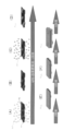
- FIG. 2 is a schematic explanatory view of a step of forming a platinum atomic layer by the UPD-platinum substitution method.
- UPD-platinum substitution method a metal surface is coated with a monolayer of copper. Then, it is immersed in a hydrochloric acid solution containing chloroplatinate ions to replace copper and platinum to form a monolayer of platinum.
- a metal nanosheet 1 supported on carbon is supported on an electrode.
- a copper monoatomic layer is deposited under-potential on the metal nanosheet as shown in FIGS.
- the copper atoms are replaced with platinum atoms by dipping in a chloroplatinic acid solution.
- a metal nanosheet 1 having a platinum monoatomic layer is formed.
- FIG. 2E shows the case where the UPD-platinum replacement method is applied twice.
- FIG. 2F shows the case where the UPD-platinum replacement method is applied three times.
- the UPD-platinum replacement method can be repeated a plurality of times.
- the thickness of the platinum atomic layer can be increased.
- the entire surface of the metal nanosheet 1 can be covered with the platinum atomic layer. Therefore, for example, when used as a catalyst, there is an advantage that the low-activity portion without the platinum atomic layer 2 can be reduced as much as possible. .
- the platinum atomic layer 2 may be formed by the above-described UPD-platinum substitution method, but may be formed by another method in which the platinum atomic layer is provided at a monoatomic layer level or a monoatomic layer stack. Good.
- a platinum atomic layer may be provided by the method described in Patent Document 1.
- a carbon carrier carrying metal nanosheets is prepared, added to water, subjected to ultrasonic treatment to disperse the carrier in water, and then an amount of platinum complex sufficient to cover the metal nanosheet (two (Valent or tetravalent) is added and stirred under an inert atmosphere for a predetermined time. Thereafter, centrifugation and washing with ultrapure water are performed, followed by drying to form the platinum atomic layer 2 on the surface of the metal nanosheet.
- a solution containing divalent platinum ions or tetravalent platinum ions is used.
- the solution containing divalent platinum ions or tetravalent platinum ions include, for example, an aqueous solution of tetrachloroplatinic (II) acid, an aqueous solution of potassium tetrachloroplatinum (II), an aqueous solution of diamminedichloroplatinum (II), and diammine dinitroplatinum.
- aqueous solution of (II), an aqueous solution of tetraammineplatinum (II) chloride (monohydrate), an aqueous solution of hexachloroplatinum (IV) acid, an aqueous solution of potassium hexachloroplatinum (IV), and the like can be mentioned.
- platinum ions may exist in the solution in any state of an anion complex, a cation complex, and a nonionic complex.
- the thickness of the platinum atomic layer 2 differs depending on whether it is a monoatomic layer or a monoatomic layer stack, but is preferably in the range of 0.3 nm or more and 1.0 nm or less, for example. If the thickness of the platinum atomic layer 2 is less than 0.3 nm, it is difficult for the platinum atomic layer 2 to cover the entire surface of the metal nanosheet 1. As a result, when used as a catalyst, for example, a low-activity portion without the platinum atomic layer 2 is increased. On the other hand, when the thickness of the platinum atomic layer 2 exceeds 1.0 nm, the platinum atomic layer 2 becomes thick. As a result, when used as a catalyst, for example, platinum atoms that do not function as a catalyst are relatively increased, the catalytic activity per mass of platinum is reduced, and the amount of expensive platinum used cannot be reduced.
- the core-shell structured nanosheet 10 according to the present invention is preferably used as an electrode catalyst for a fuel cell.
- the catalytic activity of the fuel cell electrode catalyst especially the electrode catalyst for a polymer electrolyte fuel cell
- the catalyst performance based on aggregation and particle growth like a nanoparticle catalyst is improved. It is possible to suppress the decrease.
- the core-shell structure type nanosheet 10 according to the present invention can be used particularly for a cathode catalyst or an anode catalyst.
- a cathode catalyst When used as a cathode catalyst, the oxygen reduction activity can be further increased, and a decrease in catalyst performance can be suppressed.
- an anode catalyst carbon monoxide poisoning resistance (CO poisoning resistance) and durability can be further enhanced.
- the core-shell structured nanosheet is supported on carbon.
- Various carbons can be used as the carrier at this time.
- the carrier include carbon black, carbon nanotube, and graphene.
- the size of the carbon can be arbitrarily selected in relation to the size of the metal ruthenium nanosheet.
- the present invention provides a novel core-shell structured nanosheet 10 that has not been obtained in the past.
- the core-shell structure type nanosheet 10 can reduce the useless atom which cannot contribute to reaction as much as possible.
- the core-shell structured nanosheet 10 can improve the catalytic activity per mass of platinum and can reduce expensive platinum.
- the core-shell structure type nanosheet 10 is used as, for example, a catalyst, there is an extraordinary effect that a decrease in the catalyst performance can be suppressed.
- a “core-shell structured nanosheet composed of a metal ruthenium nanosheet core / platinum shell” in which a platinum atomic layer is provided on the surface of a metal ruthenium nanosheet will be described as an example.
- the type of the metal nanosheet is not limited to the metal ruthenium nanosheet as long as it is a core-shell structure type nanosheet composed of a metal nanosheet core / platinum shell.
- Example 1 First, a ruthenium oxide nanosheet is prepared, and then the ruthenium oxide nanosheet is supported on carbon using a ruthenium oxide nanosheet colloid. Thereafter, reduction was performed to obtain a metal ruthenium nanosheet / carbon support. Finally, a platinum atomic layer was provided on the surface of the metal ruthenium nanosheet to produce a “core-shell structured nanosheet consisting of a metal ruthenium nanosheet core / platinum shell”. Hereinafter, it demonstrates in order.
- layered ruthenium oxide for obtaining a ruthenium oxide nanosheet was prepared.
- Layered ruthenium oxide is a composite oxide of ruthenium oxide and an alkali metal (sodium, potassium, etc.).
- K 0.2 RuO 2.1 ⁇ nH 2 O and Na 0.2 RuO 2 ⁇ nH 2 O can be separated into a single layer by using the ion exchange ability, so that a ruthenium oxide nanosheet is obtained. be able to.
- ruthenium oxide (RuO 2 ) and potassium carbonate (K 2 CO 3 ) are weighed so as to have a molar ratio of 8: 5, and wet-mixed in acetone for 1 hour using an agate mortar. did. Thereafter, the mixed powder was pelletized using a tablet molding machine. The pellet was placed on an alumina boat and fired at 850 ° C. for 12 hours in a tubular furnace under an argon flow. After firing, the pellets were pulverized, washed with ion exchange distilled water, and the supernatant was removed. A layered ruthenium oxide (potassium type) was obtained by repeating this operation until the supernatant became neutral.
- RuO 2 ruthenium oxide
- K 2 CO 3 potassium carbonate
- layered ruthenium oxide (potassium type)
- acid treatment is performed in a water bath at 60 ° C. for 72 hours, so that K + ions contained in layered ruthenium oxide (potassium type) are converted into hydrogen ions (protons). ).
- the supernatant was removed by washing with ion-exchanged distilled water. This operation was repeated until the supernatant became neutral.
- layered ruthenium oxide hydrogen type: H 0.2 RuO 2.1
- 10% TBAOH (tetrabutylammonium hydroxide) aqueous solution as a release agent for obtaining a ruthenium oxide nanosheet was added to the obtained layered ruthenium oxide (hydrogen type: H 0.2 RuO 2.1 ).
- layered ruthenium oxide (hydrogen type: H 0.2 RuO 2.1 ) was added to distilled water and shaken for 10 days.
- the ruthenium oxide nanosheets peeled off by this method were centrifuged at 2000 rpm for 30 minutes, and then the supernatant was collected to obtain a ruthenium oxide nanosheet colloid having a concentration of 10 mg / mL with ultrapure water.
- the dimensions of the ruthenium oxide nanosheet in the colloid were measured as follows. First, the silicon wafer was immersed in a 1% by weight polyvinyl alcohol-polydiallylamine copolymer aqueous solution for 10 minutes, washed with water several times, and dried. Next, 10 mg / mL ruthenium oxide nanosheet colloid was diluted to form a 0.08 mg / mL ruthenium oxide nanosheet aqueous dispersion, immersed in this aqueous dispersion for 2 minutes, washed several times with water, and dried. . The dimension of the ruthenium oxide nanosheet was measured from an observation image of an atomic force microscope (AFM) image.
- AFM atomic force microscope
- the maximum length and the length orthogonal at the midpoint of the maximum length were measured, and the average of them was taken as the “dimension”. This was repeated at 70 to 80 locations.
- the dimensions of the ruthenium oxide nanosheets were 70% or more of the ruthenium oxide nanosheets of 150 nm to 550 nm and the mode diameter was 200 nm to 450 nm.
- the catalyst dispersion described above was dropped onto the end face of the electrode that had been surface cleaned to prepare an electrode for the experiment. At this time, the weight of the metal ruthenium nanosheet on the end face of the electrode was 0.45 ⁇ g. This electrode was naturally dried at room temperature, and then vacuum-dried at 60 ° C. for 30 minutes.
- This electrode was held at 0.3 V for 20 minutes against a reversible hydrogen electrode (RHE) in 0.5 MH 2 SO 4 containing 2 mM copper sulfate degassed with nitrogen gas. In this way, a copper monoatomic layer was deposited under-potentially on the surface of the metal ruthenium nanosheet.
- This electrode was quickly immersed in a degassed 0.5M potassium tetrachloroplatinate (II) solution and allowed to pass for 20 minutes, thereby substituting the platinum atoms with platinum atoms, and forming a metal ruthenium nanosheet core / platinum shell ( A core-shell structure type nanosheet comprising UPD-platinum substitution method: once) was obtained.
- the number of UPD-platinum substitution methods by underpotential precipitation and platinum substitution can be repeated, and the number of repetitions is shown in parentheses.
- Electrochemical measurement of the obtained core-shell structure type nanosheet was performed by RDE (rotary electrode) measurement using a standard three-electrode type electrochemical cell.
- As the sample electrode glassy carbon having a diameter of 6 mm provided with the core-shell structure type nanosheet was used. Carbon fibers (manufactured by Toho Tenax, HTA-3K, filament number: 3000) were used as the counter electrode.
- a reversible hydrogen electrode (RHE) was used as a reference electrode.
- RDE measurements were performed in 0.1M HClO 4 electrolyte. The following electrochemical measurements were made with this RDE measurement.
- FIG. 3A shows an electrode catalyst in which a metal ruthenium nanosheet is supported on carbon.
- FIG. 3B shows an electrode catalyst in which a core-shell structured nanosheet composed of a metal ruthenium nanosheet core / platinum shell (UPD-platinum substitution method: twice) is supported on carbon.
- FIG. 3C shows an electrode catalyst in which a core-shell structure type nanosheet composed of a metal ruthenium nanosheet core / platinum shell (UPD-platinum substitution method: 4 times) is supported on carbon.
- the nanosheet form was able to be observed.
- FIG. 4 shows the number of repetitions of the formation step of the platinum atomic layer by the UPD-platinum substitution method (1 to 5 times) and the obtained metal ruthenium nanosheet core / platinum shell (UPD-platinum substitution method: once to 5 times).
- ECSA electrochemically active surface area
- the electrochemically active surface area (ECSA) was evaluated using the result of cyclic voltammogram using the above-described sample electrode for RDE measurement. Specifically, the electrochemically active surface area (ECSA) was calculated from the amount of electricity in the hydrogen adsorption region of the cyclic voltammogram using each sample electrode that had been subjected to the UPD-platinum substitution method 1 to 5 times. ECSA increased by repeating the UPD-platinum substitution method, and the difference between the first time and the second time was particularly large. Moreover, it increased gradually after 2 times. The large difference between the first time and the second time is considered to be based on the coverage ratio of the platinum atomic layer on the surface of the metal ruthenium nanosheet.
- the platinum atom layer is not sufficiently covered at one time, and the platinum atom layer is sufficiently covered by repeating twice or more times. Moreover, it is thought that the increase by repeating twice or more originates in the increase in surface roughness (fine roughness). Since the ECSA of the conventionally known Pt nanoparticles (average diameter 3 nm) / carbon support was 79 m 2 / (g-Pt), the core-shell structure nanosheet obtained in Experimental Example 1 was 1.6 An increase in ECSA of fold to 1.9 times was confirmed.
- FIG. 5 (a) is a CO stripping voltammogram in which a conventionally known electrocatalyst (Pt nanoparticles / C) supporting Pt nanoparticles on carbon is assigned by the amount of platinum.
- FIG. 5 (b) is a CO stripping voltammogram assigned by the amount of PtRu for a conventionally known electrocatalyst (PtRu / C) in which PtRu alloy nanoparticles are supported on carbon.
- FIG. 5 (c) shows the CO stripping in which the core-shell structured nanosheet of the present invention consisting of a metal ruthenium nanosheet core / platinum shell (UPD-platinum replacement method: 2 times) is supported on carbon and allocated by the amount of PtRu. It is a voltammogram.
- a core-shell structured nanosheet composed of a metal ruthenium nanosheet core / platinum shell (UPD-platinum substitution method: 2 times) has a CO oxidation peak potential of 0.57 V, and has a CO oxidation reaction activity equivalent to PtRu / C. all right. From this, it can be expected that a core-shell structured nanosheet composed of a metal ruthenium nanosheet core / platinum shell (UPD-platinum substitution method: twice) is used as an anode catalyst.
- FIG. 6 (a) shows a linear sweep in hydrogen in which PtRu amount is assigned to an electrocatalyst having a core-shell structure type nanosheet consisting of metal ruthenium nanosheet core / platinum shell (UPD-platinum substitution method: 2 times) supported on carbon. It is a voltammogram.
- FIG. 6B is a stripping voltammogram in hydrogen assigned to the amount of PtRu for an electrocatalyst having PtRu nanoparticles supported on carbon.
- the current value of the hydrogen oxidation reaction for the core-shell structured nanosheet composed of the metal ruthenium nanosheet core / platinum shell is higher than the current value of PtRu / C.
- the hydrogen oxidation reaction activity was high.
- FIG. 7 (a) shows an electrode catalyst in which a core-shell structured nanosheet consisting of a metal ruthenium nanosheet core / platinum shell (UPD-platinum substitution method: 2 times) is supported on carbon in 300 ppm CO / H 2 assigned by PtRu amount. It is a chronoamperogram.
- FIG. 7B is a chronoamperogram in 300 ppm CO / H 2 assigned by the amount of PtRu for an electrode catalyst in which PtRu nanoparticles are supported on carbon.
- the hydrogen oxidation reaction current of the core-shell structured nanosheet consisting of the metal ruthenium nanosheet core / platinum shell is 1 hour (3600 seconds) after the start of measurement. It was higher than PtRu / C in FIG. From this, it was found that the core-shell structured nanosheet composed of the metal ruthenium nanosheet core / platinum shell (UPD-platinum substitution method: twice) has high CO resistance.
- FIG. 9 (a) is a graph of the oxidation-reduction reaction (ORR) activity assigned by the amount of Pt for an electrode catalyst in which Pt nanoparticles are supported on a carbon support.
- FIG. 9B is a graph of the ORR activity assigned by the amount of Pt in an electrode catalyst in which a core-shell structured nanosheet consisting of a metal ruthenium nanosheet core / platinum shell (UPD-platinum substitution method: 4 times) is supported on carbon. .
- FIG. 9 (a) is a graph of the oxidation-reduction reaction (ORR) activity assigned by the amount of Pt for an electrode catalyst in which Pt nanoparticles are supported on a carbon support.
- FIG. 9B is a graph of the ORR activity assigned by the amount of Pt in an electrode catalyst in which a core-shell structured nanosheet consisting of a metal ruthenium nanosheet core / platinum shell (UPD-platinum substitution method: 4 times) is supported on carbon. .
- the core-shell structure type nanosheet composed of a metal ruthenium nanosheet core / platinum shell (UPD-platinum substitution method: 4 times) is 1068 A / (g -Pt).
- the core-shell structure type nanosheet composed of metal ruthenium nanosheet core / platinum shell (UPD-platinum substitution method: 5 times) also showed higher ORR activity than Pt nanoparticles / C.
- FIG. 10A is a plot of ECSA reduction rate when the electrocatalyst having Pt nanoparticles supported on carbon is normalized by initial ECSA.
- FIG. 10 (b) shows an ECSA reduction rate when the core-shell structured nanosheet composed of a metal ruthenium nanosheet core / platinum shell (UPD-platinum replacement method: 4 times) is supported on carbon and normalized by the initial ECSA. Is a plot of FIG.
- the degree of ECSA decrease in the core-shell structured nanosheet composed of the metal ruthenium nanosheet core / platinum shell is higher than that in the case of Pt nanoparticles / C. It was not remarkable, and it was found that the core-shell structured nanosheet composed of the metal ruthenium nanosheet core / platinum shell (UPD-platinum substitution method: twice) has higher durability than the Pt nanoparticle / C.
Landscapes
- Chemical & Material Sciences (AREA)
- Chemical Kinetics & Catalysis (AREA)
- Electrochemistry (AREA)
- General Chemical & Material Sciences (AREA)
- Engineering & Computer Science (AREA)
- Materials Engineering (AREA)
- Organic Chemistry (AREA)
- Composite Materials (AREA)
- Manufacturing & Machinery (AREA)
- Catalysts (AREA)
- Fuel Cell (AREA)
- Inert Electrodes (AREA)
Abstract
【課題】新規なコアシェル構造型ナノシートを提供するとともに、燃料電池の電極触媒として用いた場合、触媒活性を向上するとともに触媒性能の低下を抑制できるコアシェル構造型ナノシートを提供する。 【解決手段】金属ナノシート1と、その金属ナノシート1の表面に設けられた白金原子層2とを有するコアシェル構造型ナノシート10により上記課題を解決する。このコアシェル構造型ナノシート10において、白金原子層2は金属ナノシート1の表面の全部に設けられていることが好ましい。また、このコアシェル構造型ナノシート10は、燃料電池等のカソード触媒又はアノード触媒として用いることができる。なお、金属ナノシート1は、厚さが0.2nm以上0.3nmの範囲内であり、面内方向の長さが数十nm以上数μm以下の範囲内であることが好ましい。
Description
本発明は、コアシェル構造型ナノシートに関する。さらに詳しくは、金属ナノシートをコアとし、白金をシェルとしたコアシェル構造型ナノシートに関するものである。これは、例えば固体高分子形燃料電池等の電極触媒への適用が可能である。
固体高分子形燃料電池の本格普及には、電極触媒の高性能化が求められている。現在の実用的な触媒性能を示すものとしては、Ptナノ粒子をカーボンに担持した触媒(Ptナノ粒子/C触媒という。)が知られている。
しかし、Ptナノ粒子/C触媒は、高価で資源量の少ない白金をナノ粒子として使用しているため、白金使用量の削減が検討課題とされている。その解決手段の一例として、PtCo合金ナノ粒子をカーボンに担持した触媒(PtCoナノ粒子/C触媒という。)が提案されている。また、他の例として、AuやRuのナノ粒子をコアとし、その表面にPt原子層が設けられたコアシェル構造をカーボンに担持した電極触媒が提案されている(特許文献1及び非特許文献1参照)。
Auナノ粒子の表面にPt原子層を設けたコアシェル構造をカーボンに担持した電極触媒は、Pt量を少なくでき、さらに表面積を増大できる。そのため、Ptの質量あたりの触媒活性を向上させ、Pt量の削減を図ることができるとされている。さらに、その電極触媒は、Auナノ粒子をコアとしているので、安定であるという利点もある。なお、この電極触媒において、Auナノ粒子の表面にPt原子層を設ける手段としては、電気化学反応による銅の単原子層析出法(Cu-UPD法)が適用されている。
また、Ruナノ粒子の表面にPt原子層を1~3モノレイヤーで設けたコアシェル触媒は、Pt/C触媒と比較して3倍~5倍程度高い酸素還元反応活性を有することが報告されている(非特許文献1参照)。
L.Yang, M.B.Vukmirovic, D.Su, K.Sasaki, J.A.Herron, M.Mavrikakis, S.Liao, R.R.Adzic, J.Phys.Chem., C2013, 117(4), 1748‐1753.
従来提案されているPtナノ粒子やPtCoナノ粒子を用いた電極触媒は、ナノ粒子の直径が約3nm程度であり、そのナノ粒子はおよそ600個程度の原子で構成されていると考えられる。そのため、ナノ粒子の構成原子のうち、粒子表面に露出している原子数の割合は50%程度であり、反応に寄与できないナノ粒子内部の原子が無駄になっている。
特許文献1及び非特許文献1で提案された電極触媒は、Ptナノ粒子の代わりにAuやRuのナノ粒子を採用し、そのナノ粒子の表面にPt原子層を設けているため、粒子内部のPt原子が無駄にならないという利点がある。そのため、Ptの質量あたりの触媒活性を向上させることができるとともに、高価なPt量の削減を図ることができるという利点がある。しかしながら、この電極触媒は、コア粒子として、Ptナノ粒子と同様に高価なAuやRuのナノ粒子を採用している。さらに、ナノ粒子を利用した電極触媒は、燃料電池の作動中に、そのナノ粒子が凝集及び/又は粒子成長し、触媒性能が低下するおそれがある。
本発明者は、燃料電池の電極触媒の触媒活性のさらなる向上と、ナノ粒子触媒のような凝集や粒子成長に基づく触媒性能の低下の抑制とを検討している過程で、新規なコアシェル構造型のナノシートを開発した。
本発明の目的は、新規なコアシェル構造型ナノシートを提供するものである。
本発明に係るコアシェル構造型ナノシートは、金属ナノシートと、当該金属ナノシートの表面に設けられた白金原子層とを有することを特徴とする。
この発明によれば、金属ナノシートの表面に白金原子層が設けられているので、次のことができる。(1)従来のナノ粒子を用いた場合とは異なり、反応に寄与できない無駄な原子を極力少なくすることができる。(2)白金原子層が金属ナノシートの表面に設けられている。そのため、例えば、触媒として利用した場合、白金の質量あたりの触媒活性を向上させることができる。さらに、高価な白金の削減を図ることができる。(3)ナノシート構造であるので、従来のナノ粒子を利用した場合とは異なり、ナノ粒子の凝集及び/又は粒子成長が起こりにくい。そのため、例えば、触媒として利用した場合に、その触媒性能の低下を抑制できる。
本発明に係るコアシェル構造型ナノシートにおいて、前記白金原子層が、前記金属ナノシートの表面の全部に設けられているように構成できる。この発明によれば、白金原子層が金属ナノシートの表面の全部に設けられているので、例えば触媒として利用した場合、白金原子層がない低活性部分を極力低減できる。
本発明に係るコアシェル構造型ナノシートにおいて、電極触媒として用いることが好ましい。この発明によれば、燃料電池等の電極触媒として用いるので、電極触媒(例えば固体高分子形燃料電池用電極触媒等)の触媒活性のさらなる向上と、ナノ粒子触媒のような凝集や粒子成長に基づく触媒性能の低下の抑制とを実現することができる。
本発明に係るコアシェル構造型ナノシートにおいて、前記電極触媒は、カソード触媒又はアノード触媒に用いることができる。この発明によれば、カソード触媒として用いた場合においては、酸素還元活性をより高めることができるとともに、触媒性能の低下を抑制することができる。また、アノード触媒として用いた場合においては、一酸化炭素被毒耐性(CO被毒耐性)及び耐久性をより高めることができる。
本発明によれば、従来にない新規なコアシェル構造型ナノシートを提供することができた。
また、本発明に係るコアシェル構造型ナノシートによれば、次のことができる。(1)従来のナノ粒子を用いた場合とは異なり、反応に寄与できない無駄な原子を極力少なくすることができる。(2)例えば触媒として利用した場合は、白金の質量あたりの触媒活性を向上させることができる。さらに、高価な白金の使用量の削減を図ることができる。(3)ナノ粒子の凝集及び/又は粒子成長が起こりにくいので、例えば触媒として利用した場合に、その触媒性能の低下を抑制できる。
以下、本発明に係るコアシェル構造型ナノシートについて詳しく説明する。なお、本発明の範囲は、以下の実施形態及び実施例等の記載内容のみに限定されない。
[コアシェル構造型ナノシート]
本発明は、新規なコアシェル構造型ナノシート10である。そのコアシェル構造型ナノシート10は、図1に示すように、金属ナノシート1と、その金属ナノシート1の表面に設けられた白金原子層2とを有する。白金原子層2は、図2に示すように、アンダーポテンシャル析出法-白金置換法(本願では「UPD-白金置換法」と略す。)で形成され、その形成ステップの繰り返し回数により、単原子層が積層されて形成されている。
本発明は、新規なコアシェル構造型ナノシート10である。そのコアシェル構造型ナノシート10は、図1に示すように、金属ナノシート1と、その金属ナノシート1の表面に設けられた白金原子層2とを有する。白金原子層2は、図2に示すように、アンダーポテンシャル析出法-白金置換法(本願では「UPD-白金置換法」と略す。)で形成され、その形成ステップの繰り返し回数により、単原子層が積層されて形成されている。
こうしたコアシェル構造型ナノシート10は、金属ナノシート1の表面に白金原子層2を有する。そのため、次のことができる。(1)従来のナノ粒子を用いた場合とは異なり、反応に寄与できない無駄な原子を極力少なくすることができる。(2)白金原子層2が金属ナノシート1の表面に設けられているので、例えば触媒として利用した場合、白金の質量あたりの触媒活性を向上させることができる。また、高価な白金の使用量の削減を図ることができる。(3)ナノシート構造であるので、従来のナノ粒子を利用した場合とは異なり、ナノ粒子の凝集及び/又は粒子成長が起こりにくいため、例えば触媒として利用した場合に、その触媒性能の低下を抑制できる。
以下、コアシェル構造型ナノシートの構成要素について説明する。
(金属ナノシート)
金属ナノシート1は、鱗片形状のシート状物質である。その厚さは、理論的には約0.2nm~0.3nmであり、実測ではnmオーダー~サブnmオーダーである。こうした厚さは、金属ナノシート1が単原子層で形成されているか、単原子層の積層体で構成されているかで異なる。いずれの金属ナノシート1とするかは、その構成材料の種類、作製のし易さ、特性(例えば触媒特性)等で任意に選択される。また、金属ナノシート1の面内方向の最大長さは、数百nm~μmオーダーであり、その最大長さの中間点を直交する長さも数百~μmオーダーである。こうした金属ナノシート1は極めて薄いことから、従来のナノ粒子を用いた場合とは異なり、シート材料にかかわらず、反応に寄与できない無駄な原子を極力少なくすることができる。
金属ナノシート1は、鱗片形状のシート状物質である。その厚さは、理論的には約0.2nm~0.3nmであり、実測ではnmオーダー~サブnmオーダーである。こうした厚さは、金属ナノシート1が単原子層で形成されているか、単原子層の積層体で構成されているかで異なる。いずれの金属ナノシート1とするかは、その構成材料の種類、作製のし易さ、特性(例えば触媒特性)等で任意に選択される。また、金属ナノシート1の面内方向の最大長さは、数百nm~μmオーダーであり、その最大長さの中間点を直交する長さも数百~μmオーダーである。こうした金属ナノシート1は極めて薄いことから、従来のナノ粒子を用いた場合とは異なり、シート材料にかかわらず、反応に寄与できない無駄な原子を極力少なくすることができる。
金属ナノシート1の構成材料としては、ルテニウム、イリジウム、チタン、ニオブ、バナジウム、マンガン、ニッケル、コバルト、モリブデン等を挙げることができる。上記した厚さや面内方向の寸法は、金属ナノシート1の構成材料の種類によって異なる。その変化要因は、金属ナノシートの前駆体となる金属化合物ナノシートの構成要素に基づくものである。なお、後述する実施例では、ルテニウムからなる金属ナノシート1を有するコアシェル構造型ナノシートを作製し、そのコアシェル構造型ナノシートをカーボンに担持した電極触媒を作製して触媒特性を評価している。しかし、金属ナノシート1の構成材料は、ルテニウムに限定されず、ルテニウムと同様に上記した各種の構成材料を用いて作製することができる。特に、本発明に係るコアシェル構造型ナノシートは、金属ナノシート1の表面に触媒として寄与する白金原子層を有するので、金属ナノシート自体に触媒性能が無くてもよいという利点がある。
金属ナノシート1をカーボンに担持させて電極触媒とすれば、高い性能を有する電極触媒、具体的には固体高分子形燃料電池用電極触媒の耐久性をより向上させることができる。その結果、この金属ナノシート1を用いて電極触媒を構成すれば、相対的に白金の使用量を低減させることができる。
(金属ナノシートの作製方法)
金属ナノシート1は、本出願人が既に出願した上記特許文献2に記載の方法で製造することができる。すなわち、金属ナノシート1は、金属化合物が層状に重なる層状金属化合物を準備する工程(準備工程)と、前記層状金属化合物を剥離し、金属化合物ナノシートを得る工程(剥離工程)と、前記金属化合物ナノシートを還元して金属ナノシートを得る工程(還元工程)と、を有する方法で製造することができる。この製造方法は、層状金属化合物を剥離した金属化合物ナノシートを還元することにより、層状金属化合物を前駆体とする金属ナノシート1を製造する技術であり、上記した各種の構成金属からなる金属ナノシートを製造することができる。
金属ナノシート1は、本出願人が既に出願した上記特許文献2に記載の方法で製造することができる。すなわち、金属ナノシート1は、金属化合物が層状に重なる層状金属化合物を準備する工程(準備工程)と、前記層状金属化合物を剥離し、金属化合物ナノシートを得る工程(剥離工程)と、前記金属化合物ナノシートを還元して金属ナノシートを得る工程(還元工程)と、を有する方法で製造することができる。この製造方法は、層状金属化合物を剥離した金属化合物ナノシートを還元することにより、層状金属化合物を前駆体とする金属ナノシート1を製造する技術であり、上記した各種の構成金属からなる金属ナノシートを製造することができる。
準備工程は、金属化合物が層状に重なる層状金属化合物を準備する工程である。この準備工程で準備される層状金属化合物としては、例えば、ルテニウム、イリジウム、チタン、ニオブ、バナジウム、マンガン、ニッケル、コバルト、モリブデン等の金属の硫化物、金属酸化物、金属水酸化物又はこれらの複合化合物からなる層状金属化合物である。また、層状金属化合物としては、ケイ素化合物やアルミニウム化合物等の粘土鉱物成分を含む層状金属化合物であってもよい。
層状金属化合物は、固相反応法、均一沈殿法、フラックス法を用いた合成法等の各種の方法によって得ることができる。一例として層状酸化ルテニウムを挙げる。後述の実施例では、酸化ルテニウムと炭酸カリウムとを所定量秤り取った後に湿式混合し、次に混合粉末をペレット化した後、そのペレットを焼成する。次に、焼成後のペレットを粉砕し、洗浄して、K型層状酸化ルテニウムを得る。さらにそのK型層状酸化ルテニウムを酸処理し、洗浄し、ろ過して、K誘導型の水素型層状酸化ルテニウムを得ている。なお、層状金属化合物を作製できれば、その作製工程は適宜変更可能である。
準備された層状金属化合物は、剥離工程の後に還元され、単層又は複数層の金属ナノシートになる。
剥離は、層状の金属化合物又は層状の金属ナノシートの層間に、異種イオン又は溶媒分子を侵入させて層間を広げる無限膨潤化処理を利用すればよい。
還元工程は、金属化合物ナノシートを還元し、層状金属化合物を前駆体とする金属ナノシートを得る工程である。
剥離工程によって単層又は複数層に剥離された金属化合物ナノシートを還元することにより、単層又は複数層の金属ナノシート1が得られる。なお、複数層の金属ナノシート1は、そのまま用いてもよいが、その後にさらに剥離して単層の金属ナノシート1としてもよい。
還元工程での還元は、乾式処理又は湿式処理で行うことができる。乾式処理としては、水素を含む還元性雰囲気下での熱処理を挙げることができる。一方、湿式処理としては、水素化ホウ素ナトリウム(NaBH4)等の還元性溶液への浸漬処理を挙げることができる。
金属ナノシート1は、上記したように、単層の金属ナノシート1でもよいし、複数層の金属ナノシート1でもよい。複数層の金属ナノシート1は、例えば特許文献3に示した自己組織的な薄膜形成を経由しても得ることができる。ただし、特許文献3に記載の方法に限定されるものではない。
自己組織的な薄膜形成を経由した方法の一例としては、基材表面上にカチオン性ポリマー(ポリカチオン)からなる正電荷層を形成した後、正電荷層に自己組織化反応によって、酸化ルテニウム(RuO2)ナノシート(アニオン性のナノシート/金属酸化物ナノシート)を吸着させてナノシートとポリマーとの複合薄膜を形成する。この複合薄膜である酸化ルテニウムナノシートは、厚さが2nm以下で横サイズがサブμmから数mmの範囲でナノシートが部分的に重なり合ってナノシート層の一層分が形成されているというものである。
こうした作製方法により、単層又は複数層の金属ナノシート1を得ることができる。その結果、単原子層相当の厚さオーダーの極めて薄い金属ナノシート1を得ることができる。また、複数積層された数原子層相当の厚さオーダーの厚さの金属ナノシート1を得ることもできる。
(白金原子層)
白金原子層2は、図1に示すように、金属ナノシート1の表面の全部又は一部に設けられている。特に、白金原子層2は、金属ナノシート1の表面の全部に設けられていることが好ましい。なお、「全部に設けられている」とは、白金原子層2が金属ナノシート1の表面を全て覆っているという意味である。白金原子層2が金属ナノシート1の表面の全部に設けられている場合には、例えば触媒として利用した場合、白金原子層2がない低活性な部分を極力低減できるという利点がある。
白金原子層2は、図1に示すように、金属ナノシート1の表面の全部又は一部に設けられている。特に、白金原子層2は、金属ナノシート1の表面の全部に設けられていることが好ましい。なお、「全部に設けられている」とは、白金原子層2が金属ナノシート1の表面を全て覆っているという意味である。白金原子層2が金属ナノシート1の表面の全部に設けられている場合には、例えば触媒として利用した場合、白金原子層2がない低活性な部分を極力低減できるという利点がある。
白金原子層2は、単原子層として設けられていてもよいし、単原子層が積み重なった形態(単原子層積層体)で設けられていてもよい。白金原子層2が単原子層として設けられている場合はもちろん、単原子層が積み重なって設けられている場合においても、白金原子層は薄い層として設けられている。その結果、例えば白金を触媒材料として用いる場合、従来のPtナノ粒子を触媒材料として用いる場合とは異なり、反応に寄与できない粒子内部の無駄な白金を極力少なくすることができる。そのため、白金の質量あたりの触媒活性を向上させることができる。こうしたことは、高価な白金の使用量の削減につながるという利点もある。
また、本発明では、白金原子層2をナノ粒子表面に設けているのではなく、金属ナノシート1の表面に設けているので、従来のナノ粒子を利用した場合とは異なり、ナノ粒子の凝集及び/又は粒子成長が起こりにくい。その結果、例えば触媒として利用した場合、その触媒性能の低下を抑制できるという格別の効果がある。
(白金原子層の形成方法)
白金原子層2は、金属ナノシート1の表面に形成される。白金原子層2の形成方法としては、特に限定されず、種々の析出方法で形成可能である。金属ナノシート1の表面への白金原子層2の析出方法としては、アンダーポテンシャル析出法(以下、「UPD-白金置換法」と略す。)を挙げることができる。その他、鉛や水素を用いた析出法であってもよいし、それ以外の析出法であってもよい。以下では、UPD-白金置換法で白金原子層を形成する場合を例にして説明する。
白金原子層2は、金属ナノシート1の表面に形成される。白金原子層2の形成方法としては、特に限定されず、種々の析出方法で形成可能である。金属ナノシート1の表面への白金原子層2の析出方法としては、アンダーポテンシャル析出法(以下、「UPD-白金置換法」と略す。)を挙げることができる。その他、鉛や水素を用いた析出法であってもよいし、それ以外の析出法であってもよい。以下では、UPD-白金置換法で白金原子層を形成する場合を例にして説明する。
図2は、UPD-白金置換法で白金原子層を形成するステップの模式的な説明図である。このUPD-白金置換法は、金属の表面を銅の単原子層で被覆する。その後、塩化白金酸イオンが存在する塩酸溶液に浸漬して、銅と白金とを置換させ、白金の単原子層を形成するという方法である。
このUPD-白金置換法を利用して金属ナノシート1の表面に白金原子層2を形成する方法としては、先ず、金属ナノシート1をカーボンに担持させたものを電極に担持させる。この電極を銅イオンを含む溶液中で電位をかけた状態で保持することにより、図2(A)(B)に示すように、金属ナノシート上に銅の単原子層をアンダーポテンシャル析出させる。その後、図2(C)に示すように、塩化白金酸溶液に浸漬して銅原子を白金原子に置換する。こうして、図2(D)に示すように、白金の単原子層が形成された金属ナノシート1が形成される。
さらに、この方法を繰り返すことにより、図2(E)(F)に示すように、単原子層を積層することができる。図2(E)は、UPD-白金置換法を2回適用した場合である。図2(F)はUPD-白金置換法を3回適用した場合である。このように、UPD-白金置換法は複数回繰り返して行うことができる。その結果、白金原子層の厚さを厚くすることができる。特に2回以上繰り返すことにより、金属ナノシート1の表面全体を白金原子層が覆うことができるので、例えば触媒として利用した場合、白金原子層2がない低活性な部分を極力低減できるという利点がある。
白金原子層2は、上記したUPD-白金置換法で形成してもよいが、白金原子層を単原子層レベルで設けたり単原子層の積層形態で設けたりする他の方法で形成してもよい。そうした他の方法としては、特許文献1に記載の方法で白金原子層を設けてもよい。例えば、金属ナノシートを担持させたカーボン担体を用意し、これを水中に加え、超音波処理を行って担体を水中で分散させた後、金属ナノシートを被覆するのに十分な量の白金錯体(二価又は四価)を添加し、不活性雰囲気下で所定時間攪拌する。その後、遠心分離と超純水による洗浄を行い、その後乾燥して、金属ナノシートの表面に白金原子層2を形成する。
このときの白金錯体溶液としては、二価白金イオン又は四価白金イオンを含む溶液が用いられる。二価白金イオン又は四価白金イオンを含む溶液としては、例えば、テトラクロロ白金(II)酸の水溶液、テトラクロロ白金(II)酸カリウムの水溶液、ジアンミンジクロロ白金(II)の水溶液、ジアンミンジニトロ白金(II)の水溶液、テトラアンミン白金(II)塩化物(一水和物)の水溶液、ヘキサクロロ白金(IV)酸の水溶液、ヘキサクロロ白金(IV)酸カリウムの水溶液等を挙げることができる。また、これらの白金イオンは、陰イオン錯体、陽イオン錯体、非イオン錯体のいずれの状態で溶液中に存在していてもよい。
白金原子層2の厚さは、単原子層とするか、単原子層の積層体とするかで異なるが、例えば、0.3nm以上、1.0nm以下の範囲内であることが好ましい。白金原子層2の厚さが0.3nm未満では、白金原子層2が金属ナノシート1の表面の全てを覆うことが難しくなる。その結果、例えば触媒として利用した場合、白金原子層2がない低活性な部分が増す。一方、白金原子層2の厚さが1.0nmを超えると、白金原子層2が厚くなる。その結果、例えば触媒として利用した場合、触媒として機能しない白金原子が相対的に増すことになり、白金の質量あたりの触媒活性が低下し、高価な白金の使用量の削減を図ることができない。
(コアシェル構造型ナノシート)
本発明に係るコアシェル構造型ナノシート10は、燃料電池の電極触媒として用いることが好ましい。燃料電池の電極触媒として用いた場合、燃料電池の電極触媒(特に固体高分子形燃料電池用電極触媒)の触媒活性のさらなる向上と、ナノ粒子触媒のような凝集や粒子成長に基づく触媒性能の低下の抑制とを実現することができる。
本発明に係るコアシェル構造型ナノシート10は、燃料電池の電極触媒として用いることが好ましい。燃料電池の電極触媒として用いた場合、燃料電池の電極触媒(特に固体高分子形燃料電池用電極触媒)の触媒活性のさらなる向上と、ナノ粒子触媒のような凝集や粒子成長に基づく触媒性能の低下の抑制とを実現することができる。
本発明に係るコアシェル構造型ナノシート10は、特に、カソード触媒又はアノード触媒に用いることができる。カソード触媒として用いた場合は、酸素還元活性をより高めることができるとともに、触媒性能の低下を抑制することができる。また、アノード触媒として用いた場合は、一酸化炭素被毒耐性(CO被毒耐性)及び耐久性をより高めることができる。
こうした電極触媒とするためには、コアシェル構造型ナノシートをカーボンに担持した形態である必要がある。このときの担体としては、各種のカーボンを用いることができる。担体としては、例えば、カーボンブラック、カーボンナノチューブ、グラフェン等を挙げることができる。カーボンの大きさは、金属ルテニウムナノシートの大きさとの関係で任意に選択することができる。
以上説明したように、本発明では、従来にない新規なコアシェル構造型ナノシート10を提供した。そして、そのコアシェル構造型ナノシート10は、反応に寄与できない無駄な原子を極力少なくすることができる。また、コアシェル構造型ナノシート10は、白金の質量あたりの触媒活性を向上させることができるとともに、高価な白金の低減を図ることができる。さらに、コアシェル構造型ナノシート10を、例えば触媒として利用した場合、その触媒性能の低下を抑制できるという格別の効果を奏する。
以下、本発明を具体的に説明する。以下の実験例では、金属ルテニウムナノシートの表面に白金原子層を設けた「金属ルテニウムナノシートコア/白金シェルからなるコアシェル構造型ナノシート」を例にして説明する。ただし、金属ナノシートコア/白金シェルからなるコアシェル構造型ナノシートであれば、金属ナノシートの種類も金属ルテニウムナノシートに限定されない。
[実験例1]
最初に、酸化ルテニウムナノシートを作製し、次に、酸化ルテニウムナノシートコロイドを用いて酸化ルテニウムナノシートをカーボンに担持させる。その後、還元して金属ルテニウムナノシート/カーボン担体とした。最後に、金属ルテニウムナノシートの表面に白金原子層を設けて、「金属ルテニウムナノシートコア/白金シェルからなるコアシェル構造型ナノシート」を作製した。以下、順に説明する。
最初に、酸化ルテニウムナノシートを作製し、次に、酸化ルテニウムナノシートコロイドを用いて酸化ルテニウムナノシートをカーボンに担持させる。その後、還元して金属ルテニウムナノシート/カーボン担体とした。最後に、金属ルテニウムナノシートの表面に白金原子層を設けて、「金属ルテニウムナノシートコア/白金シェルからなるコアシェル構造型ナノシート」を作製した。以下、順に説明する。
<酸化ルテニウムナノシートの作製>
最初に、酸化ルテニウムナノシートを得るための層状酸化ルテニウムを作製した。層状酸化ルテニウムは、酸化ルテニウムとアルカリ金属(ナトリウム、カリウム等)との複合酸化物である。中でもK0.2RuO2.1・nH2O、及びNa0.2RuO2・nH2Oは、イオン交換能を利用することで層一枚単位にまで層剥離することが可能であるので、酸化ルテニウムナノシートを得ることができる。
最初に、酸化ルテニウムナノシートを得るための層状酸化ルテニウムを作製した。層状酸化ルテニウムは、酸化ルテニウムとアルカリ金属(ナトリウム、カリウム等)との複合酸化物である。中でもK0.2RuO2.1・nH2O、及びNa0.2RuO2・nH2Oは、イオン交換能を利用することで層一枚単位にまで層剥離することが可能であるので、酸化ルテニウムナノシートを得ることができる。
具体的には、先ず、酸化ルテニウム(RuO2)と炭酸カリウム(K2CO3)とをモル比8:5の割合となるように量り取り、メノウ乳鉢を用いてアセトン中で1時間湿式混合した。その後、錠剤成形器を用いて混合粉末をペレット化した。このペレットをアルミナボートにのせ、管状炉にてアルゴン流通下で850℃、12時間焼成した。焼成後、ペレットを粉砕し、イオン交換蒸留水で洗浄し、上澄み液を取り除いた。この操作を上澄み液が中性になるまで繰り返したものを層状酸化ルテニウム(カリウム型)とした。
次に、層状酸化ルテニウム(カリウム型)に1MのHClを加え、60℃のウォーターバス内で72時間酸処理をして、層状酸化ルテニウム(カリウム型)に含まれるK+イオンを水素イオン(プロトン)に置換した。その後、イオン交換蒸留水で洗浄し上澄み液を取り除いた。この操作を上澄み液が中性になるまで繰り返し、ろ過後に、層状酸化ルテニウム(水素型:H0.2RuO2.1)の粉末を得た。
<酸化ルテニウムナノシートコロイドの調製>
次に、得られた層状酸化ルテニウム(水素型:H0.2RuO2.1)に、酸化ルテニウムナノシートを得る剥離剤としての10%TBAOH(テトラブチルアンモニウムヒドロキシド)水溶液を加えた。層状酸化ルテニウム(水素型:H0.2RuO2.1)の濃度を、TBAOHとプロトンとの割合で、TBA+/H+=1.5、固液比=4g/Lとした。その後、層状酸化ルテニウム(水素型:H0.2RuO2.1)を蒸留水に加え、10日間振とうさせた。この方法で単層剥離させた酸化ルテニウムナノシートを2000rpmで30分間遠心分離した後、上澄み液を回収して、超純水にて濃度を10mg/mLとした酸化ルテニウムナノシートコロイドを得た。
次に、得られた層状酸化ルテニウム(水素型:H0.2RuO2.1)に、酸化ルテニウムナノシートを得る剥離剤としての10%TBAOH(テトラブチルアンモニウムヒドロキシド)水溶液を加えた。層状酸化ルテニウム(水素型:H0.2RuO2.1)の濃度を、TBAOHとプロトンとの割合で、TBA+/H+=1.5、固液比=4g/Lとした。その後、層状酸化ルテニウム(水素型:H0.2RuO2.1)を蒸留水に加え、10日間振とうさせた。この方法で単層剥離させた酸化ルテニウムナノシートを2000rpmで30分間遠心分離した後、上澄み液を回収して、超純水にて濃度を10mg/mLとした酸化ルテニウムナノシートコロイドを得た。
コロイド中の酸化ルテニウムナノシートの寸法は以下のようにして測定した。先ず、シリコンウエハを1質量%ポリビニルアルコール-ポリジアリルアミン共重合ポリマー水溶液中に10分間浸漬した後、水で数回洗浄し、乾燥した。次に、10mg/mLとした酸化ルテニウムナノシートコロイドを希釈して0.08mg/mLの酸化ルテニウムナノシート水分散液とし、この水分散液に2分浸漬した後、水で数回洗浄し、乾燥した。酸化ルテニウムナノシートの寸法は、原子間力顕微鏡(AFM)像の観察画像から測定した。具体的には、鱗片形状の酸化ルテニウムナノシートについて、最大長さとその最大長さの中点で直交する長さとを測定し、それらの平均を出して「寸法」とした。これを70~80箇所繰り返した。その結果、酸化ルテニウムナノシートの寸法は、150nm以550nm以下の酸化ルテニウムナノシートが全体の70%以上であり且つモード径が200nm以上450nm以下であった。
<金属ルテニウムナノシート/カーボン担体の作製>
次に、酸化ルテニウムナノシートコロイドを用いて酸化ルテニウムナノシートをカーボン担体に担持させた。その後、酸化ルテニウムナノシートを還元して、金属ルテニウムナノシートが担持したカーボン担体を作製した。
次に、酸化ルテニウムナノシートコロイドを用いて酸化ルテニウムナノシートをカーボン担体に担持させた。その後、酸化ルテニウムナノシートを還元して、金属ルテニウムナノシートが担持したカーボン担体を作製した。
具体的には、先ず、酸化ルテニウムナノシートを高比表面積カーボンと組み合わせるために、10mg/mLとなるようにカーボンを超純水15mL中に加えた。そして、撹拌と超音波処理をそれぞれ30分間行って分散させ、カーボン分散溶液を得た。次に、このカーボン分散溶液に、酸化ルテニウムナノシートが10質量%でカーボン担体に担持するように、任意量の酸化ルテニウムナノシートコロイドを撹拌しながらゆっくり滴下した。酸化ルテニウムナノシートコロイドの濃度は任意に調整できるが、ここでは上記のように10mg/mLとした。さらに、均一な反応を確保するために、撹拌、超音波処理、60℃での静置、デカンテーション(中性になるまで水洗浄)を順に行った。その後、120℃で12時間乾燥させた後に粉砕して、「酸化ルテニウムナノシート/カーボン担体」を得た。得られた「酸化ルテニウムナノシート/カーボン担体」をアルミナボートに載せ、管状炉にて水素と窒素との還元雰囲気下で120℃、2時間焼成して還元した。水素流量は10cc/分、窒素流量は150cc/分で、これらのガスを混合して管状炉へ流した。焼成後に粉砕して、「金属ルテニウムナノシート/カーボン担体」を得た。
<金属ルテニウムナノシートコア/白金シェルの作製>
次に、金属ルテニウムナノシートの表面に白金原子層を設けて、「金属ルテニウムナノシートコア/白金シェル」からなるコアシェル構造型ナノシートを作製した。
次に、金属ルテニウムナノシートの表面に白金原子層を設けて、「金属ルテニウムナノシートコア/白金シェル」からなるコアシェル構造型ナノシートを作製した。
具体的には、先ず、2-プロパノール/超純水溶液(75/25体積割合)10mLに、上記で得られた「金属ルテニウムナノシート/カーボン担体」5mgを混合して、触媒分散液を準備した。この触媒分散液には、試験電極に対して良好な密着性を確保するためのプロトン伝導性バインダーとして、5質量%のナフィオン(Nafion、デュポン社の登録商標)溶液45μLを加えた。こうして得られた触媒分散液を30分間超音波処理した。
金属ルテニウムナノシートの表面に白金原子層を設けるためには、「金属ルテニウムナノシート/カーボン担体」を電極上に設け、電気化学的手段であるアンダーポテンシャル析出法を適用する必要がある。そのために用いる電極として、直径6mmのグラッシーカーボンを用い、予め0.05μmの酸化アルミニウム粉末を用いてその端面をバフ研磨した。その後、真空中で60℃にて乾燥させた。この電極端面の表面は、0.5MH2SO4(25℃)電解液を使用して電気化学的な表面清浄化を行った(E=0.05~0.8V vs.RHE、v=50mV/s)。表面洗浄した電極端面に上記した触媒分散液を滴下して、実験に供する電極を作製した。このときの電極の端面上における金属ルテニウムナノシートの重量は0.45μgであった。この電極を室温で自然乾燥させ、その後60℃での真空乾燥を30分間行った。
この電極を、窒素ガスで脱気した2mM硫酸銅を含む0.5MH2SO4中で、可逆水素電極(RHE)に対して0.3Vで20分間保持した。こうして、金属ルテニウムナノシートの表面上に銅の単原子層をアンダーポテンシャル析出させた。この電極を、脱気した0.5Mテトラクロロ白金(II)酸カリウム水溶液に素早く浸漬し、そのまま20分間経過させることで、銅原子を白金原子に置換して、金属ルテニウムナノシートコア/白金シェル(UPD-白金置換法:1回)からなるコアシェル構造型ナノシートを得た。なお、このアンダーポテンシャル析出と白金置換とによるUPD-白金置換法の回数は繰り返すことができ、括弧内は繰り返し回数を示す。
[各測定とその結果]
<電気化学的測定>
得られたコアシェル構造型ナノシートの電気化学的測定は、標準的な三電極型の電気化学セルを用いたRDE(回転電極)測定で行った。試料電極として、上記したコアシェル構造型ナノシートを設けた直径6mmのグラッシーカーボンを用いた。カウンター電極として、炭素繊維(TohoTenax社製、HTA-3K、フィラメント番号:3000)を用いた。参照電極として、可逆水素電極(RHE)を用いた。RDE測定は、0.1MのHClO4電解液中で行った。以下の電気化学的測定は、このRDE測定で行った。
<電気化学的測定>
得られたコアシェル構造型ナノシートの電気化学的測定は、標準的な三電極型の電気化学セルを用いたRDE(回転電極)測定で行った。試料電極として、上記したコアシェル構造型ナノシートを設けた直径6mmのグラッシーカーボンを用いた。カウンター電極として、炭素繊維(TohoTenax社製、HTA-3K、フィラメント番号:3000)を用いた。参照電極として、可逆水素電極(RHE)を用いた。RDE測定は、0.1MのHClO4電解液中で行った。以下の電気化学的測定は、このRDE測定で行った。
<各種の触媒形態の観察>
図3(A)は、金属ルテニウムナノシートをカーボンに担持した電極触媒である。図3(B)は、金属ルテニウムナノシートコア/白金シェル(UPD-白金置換法:2回)からなるコアシェル構造型ナノシートをカーボンに担持した電極触媒である。図3(C)は、金属ルテニウムナノシートコア/白金シェル(UPD-白金置換法:4回)からなるコアシェル構造型ナノシートをカーボンに担持した電極触媒である。図3(B)と図3(C)に示すコアシェル構造型ナノシートは、いずれもナノシート形態が観察できた。
図3(A)は、金属ルテニウムナノシートをカーボンに担持した電極触媒である。図3(B)は、金属ルテニウムナノシートコア/白金シェル(UPD-白金置換法:2回)からなるコアシェル構造型ナノシートをカーボンに担持した電極触媒である。図3(C)は、金属ルテニウムナノシートコア/白金シェル(UPD-白金置換法:4回)からなるコアシェル構造型ナノシートをカーボンに担持した電極触媒である。図3(B)と図3(C)に示すコアシェル構造型ナノシートは、いずれもナノシート形態が観察できた。
<電気化学的活性表面積の評価実験>
図4は、UPD-白金置換法による白金原子層の形成ステップの繰り返し回数(1回~5回)と、得られた金属ルテニウムナノシートコア/白金シェル(UPD-白金置換法:1回~5回)からなるコアシェル構造型ナノシートをカーボンに担持した電極触媒における電気化学的活性表面積(ECSA)との関係を示すグラフである。
図4は、UPD-白金置換法による白金原子層の形成ステップの繰り返し回数(1回~5回)と、得られた金属ルテニウムナノシートコア/白金シェル(UPD-白金置換法:1回~5回)からなるコアシェル構造型ナノシートをカーボンに担持した電極触媒における電気化学的活性表面積(ECSA)との関係を示すグラフである。
電気化学的活性表面積(ECSA)の評価は、上記したRDE測定用の試料電極を用い、サイクリックボルタモグラムの結果を利用して行った。具体的には、UPD-白金置換法を1回~5回行ったそれぞれの試料電極を用い、サイクリックボルタモグラムの水素吸着領域における電気量から電気化学的活性表面積(ECSA)を算出した。ECSAは、UPD-白金置換法を繰り返すことで増加し、特に、1回と2回の差が大きかった。また、2回以降は、徐々に増加した。1回と2回の大きな差は、金属ルテニウムナノシートの表面の白金原子層の被覆割合に基づいているものと考えられる。1回では白金原子層が十分に被覆しておらず、2回以上繰り返すことにより、白金原子層が十分に被覆していることを示している。また、2回以上繰り返すことによる増加は、表面のラフネス(微細粗さ)が増加したことに起因すると考えられる。なお、従来公知のPtナノ粒子(平均直径3nm)/カーボン担体のECSAは、79m2/(g-Pt)であったので、この実験例1で得られたコアシェル構造型ナノシートによって、1.6倍~1.9倍のECSAの増加が確認できた。
<CO酸化反応活性の評価実験>
図5(a)は、Ptナノ粒子をカーボンに担持した従来公知の電極触媒(「Ptナノ粒子/C」で表す。)について、白金量で割付けたCOストリッピングボルタモグラムである。図5(b)は、PtRu合金ナノ粒子をカーボンに担持した従来公知の電極触媒(「PtRu/C」で表す。)について、PtRu量で割付けたCOストリッピングボルタモグラムである。図5(c)は、金属ルテニウムナノシートコア/白金シェル(UPD-白金置換法:2回)からなる本発明のコアシェル構造型ナノシートをカーボンに担持した電極触媒について、PtRu量で割付けたCOストリッピングボルタモグラムである。
図5(a)は、Ptナノ粒子をカーボンに担持した従来公知の電極触媒(「Ptナノ粒子/C」で表す。)について、白金量で割付けたCOストリッピングボルタモグラムである。図5(b)は、PtRu合金ナノ粒子をカーボンに担持した従来公知の電極触媒(「PtRu/C」で表す。)について、PtRu量で割付けたCOストリッピングボルタモグラムである。図5(c)は、金属ルテニウムナノシートコア/白金シェル(UPD-白金置換法:2回)からなる本発明のコアシェル構造型ナノシートをカーボンに担持した電極触媒について、PtRu量で割付けたCOストリッピングボルタモグラムである。
図5(a)に示すように、Ptナノ粒子/Cでは、CO酸化ピーク電位が0.79V程度であったが、PtRu合金/Cでは、CO酸化ピーク電位が0.57Vに低下し、CO酸化反応活性が向上していた。金属ルテニウムナノシートコア/白金シェル(UPD-白金置換法:2回)からなるコアシェル構造型ナノシートでは、CO酸化ピーク電位が0.57Vであり、PtRu/Cと同等のCO酸化反応活性であることがわかった。このことから、金属ルテニウムナノシートコア/白金シェル(UPD-白金置換法:2回)からなるコアシェル構造型ナノシートをアノード触媒として利用することが期待できる。
<水素酸化反応活性の評価実験>
図6(a)は、金属ルテニウムナノシートコア/白金シェル(UPD-白金置換法:2回)からなるコアシェル構造型ナノシートをカーボンに担持した電極触媒について、PtRu量で割付けた水素中でのリニアスイープボルタモグラムである。図6(b)は、PtRuナノ粒子をカーボンに担持した電極触媒について、PtRu量で割付けた水素中でのストリッピングボルタモグラムである。
図6(a)は、金属ルテニウムナノシートコア/白金シェル(UPD-白金置換法:2回)からなるコアシェル構造型ナノシートをカーボンに担持した電極触媒について、PtRu量で割付けた水素中でのリニアスイープボルタモグラムである。図6(b)は、PtRuナノ粒子をカーボンに担持した電極触媒について、PtRu量で割付けた水素中でのストリッピングボルタモグラムである。
図6に示すように、金属ルテニウムナノシートコア/白金シェル(UPD-白金置換法:2回)からなるコアシェル構造型ナノシートについての水素酸化反応の電流値は、PtRu/Cの電流値よりも高く、水素酸化反応活性が高かった。
<CO耐性の評価実験>
CO/H2に対する水素酸化反応活性は、水素酸化反応にかかる電流値の低下速度を評価することで、金属ルテニウムナノシートコア/白金シェル(UPD-白金置換法:2回)からなるコアシェル構造型ナノシートのCO耐性を検討した。図7(a)は、金属ルテニウムナノシートコア/白金シェル(UPD-白金置換法:2回)からなるコアシェル構造型ナノシートをカーボンに担持した電極触媒について、PtRu量で割付けた300ppmCO/H2中でのクロノアンペログラムである。図7(b)は、PtRuナノ粒子をカーボンに担持した電極触媒について、PtRu量で割付けた300ppmCO/H2中でのクロノアンペログラムである。
CO/H2に対する水素酸化反応活性は、水素酸化反応にかかる電流値の低下速度を評価することで、金属ルテニウムナノシートコア/白金シェル(UPD-白金置換法:2回)からなるコアシェル構造型ナノシートのCO耐性を検討した。図7(a)は、金属ルテニウムナノシートコア/白金シェル(UPD-白金置換法:2回)からなるコアシェル構造型ナノシートをカーボンに担持した電極触媒について、PtRu量で割付けた300ppmCO/H2中でのクロノアンペログラムである。図7(b)は、PtRuナノ粒子をカーボンに担持した電極触媒について、PtRu量で割付けた300ppmCO/H2中でのクロノアンペログラムである。
図7(a)に示すように、測定開始1時間(3600秒)後でも、金属ルテニウムナノシートコア/白金シェル(UPD-白金置換法:2回)からなるコアシェル構造型ナノシートの水素酸化反応電流は、図7(b)のPtRu/Cよりも高かった。このことから、金属ルテニウムナノシートコア/白金シェル(UPD-白金置換法:2回)からなるコアシェル構造型ナノシートは、高いCO耐性を有することがわかった。
また、耐久試験後でも、図8(a)に示すように、金属ルテニウムナノシートコア/白金シェル(UPD-白金置換法:2回)からなるコアシェル構造型ナノシートの水素酸化反応(HOR)電流は、ほとんど減少していないことに加え、図8(b)のPtRu/Cよりも高かった。このことから、金属ルテニウムナノシートコア/白金シェル(UPD-白金置換法:2回)からなるコアシェル構造型ナノシートは、高い耐久性を有することがわかった。
<ORR活性の評価実験>
図9(a)は、Ptナノ粒子がカーボン担体に担持した電極触媒について、Pt量で割付けた酸化還元反応(ORR)活性のグラフである。図9(b)は、金属ルテニウムナノシートコア/白金シェル(UPD-白金置換法:4回)からなるコアシェル構造型ナノシートをカーボンに担持した電極触媒において、Pt量で割付けたORR活性のグラフである。図9(c)は、金属ルテニウムナノシートコア/白金シェル(UPD-白金置換法:5回)からなるコアシェル構造型ナノシートをカーボンに担持した電極触媒において、Pt量で割付けたORR活性のグラフである。
図9(a)は、Ptナノ粒子がカーボン担体に担持した電極触媒について、Pt量で割付けた酸化還元反応(ORR)活性のグラフである。図9(b)は、金属ルテニウムナノシートコア/白金シェル(UPD-白金置換法:4回)からなるコアシェル構造型ナノシートをカーボンに担持した電極触媒において、Pt量で割付けたORR活性のグラフである。図9(c)は、金属ルテニウムナノシートコア/白金シェル(UPD-白金置換法:5回)からなるコアシェル構造型ナノシートをカーボンに担持した電極触媒において、Pt量で割付けたORR活性のグラフである。
酸化還元反応(ORR)活性については、金属ルテニウムナノシートコア/白金シェル(UPD-白金置換法:4回)からなるコアシェル構造型ナノシートは、Ptナノ粒子/Cの3.7倍の1068A/(g-Pt)であった。また、金属ルテニウムナノシートコア/白金シェル(UPD-白金置換法:5回)からなるコアシェル構造型ナノシートも、Ptナノ粒子/Cよりも高いORR活性を示した。
<カソード触媒の耐久性の評価実験>
カソード触媒の耐久性を、ECSAの減少率で評価した。図10(a)は、Ptナノ粒子をカーボンに担持した電極触媒について、初期ECSAで規格化したときのECSA減少率のプロットである。図10(b)は、金属ルテニウムナノシートコア/白金シェル(UPD-白金置換法:4回)からなるコアシェル構造型ナノシートをカーボンに担持した電極触媒において、初期ECSAで規格化したときのECSA減少率のプロットである。図10(c)は、金属ルテニウムナノシートコア/白金シェル(UPD-白金置換法:5回)からなるコアシェル構造型ナノシートをカーボンに担持した電極触媒において、初期ECSAで規格化したときのECSA減少率のプロットである。
カソード触媒の耐久性を、ECSAの減少率で評価した。図10(a)は、Ptナノ粒子をカーボンに担持した電極触媒について、初期ECSAで規格化したときのECSA減少率のプロットである。図10(b)は、金属ルテニウムナノシートコア/白金シェル(UPD-白金置換法:4回)からなるコアシェル構造型ナノシートをカーボンに担持した電極触媒において、初期ECSAで規格化したときのECSA減少率のプロットである。図10(c)は、金属ルテニウムナノシートコア/白金シェル(UPD-白金置換法:5回)からなるコアシェル構造型ナノシートをカーボンに担持した電極触媒において、初期ECSAで規格化したときのECSA減少率のプロットである。
図10に示すように、耐久試験において、金属ルテニウムナノシートコア/白金シェル(UPD-白金置換法:2回)からなるコアシェル構造型ナノシートにおけるECSAの低下度合いは、Ptナノ粒子/Cの場合よりも顕著ではなく、金属ルテニウムナノシートコア/白金シェル(UPD-白金置換法:2回)からなるコアシェル構造型ナノシートが、Ptナノ粒子/Cよりも高い耐久性を有することがわかった。
1 金属ナノシート
2 白金原子層
10 コアシェル構造型ナノシート
2 白金原子層
10 コアシェル構造型ナノシート
Claims (4)
- 金属ナノシートと、当該金属ナノシートの表面に設けられた白金原子層とを有することを特徴とするコアシェル構造型ナノシート。
- 前記白金原子層が、前記金属ナノシートの表面の全部に設けられている、請求項1に記載にコアシェル構造型ナノシート。
- 電極触媒として用いられる、請求項1又は2に記載のコアシェル構造型ナノシート。
- 前記電極触媒が、カソード触媒又はアノード触媒である、請求項3に記載のコアシェル構造型ナノシート。
Priority Applications (4)
| Application Number | Priority Date | Filing Date | Title |
|---|---|---|---|
| CN201680079347.7A CN108472631B (zh) | 2016-01-19 | 2016-06-08 | 核壳结构型纳米片 |
| EP16886377.7A EP3406336B1 (en) | 2016-01-19 | 2016-06-08 | Core-shell structure type nanosheet |
| US16/039,109 US10985382B2 (en) | 2016-01-19 | 2018-07-18 | Core-shell structure type nanosheet |
| US17/209,646 US11682773B2 (en) | 2016-01-19 | 2021-03-23 | Electrocatalyst |
Applications Claiming Priority (2)
| Application Number | Priority Date | Filing Date | Title |
|---|---|---|---|
| JP2016-007531 | 2016-01-19 | ||
| JP2016007531A JP6441834B2 (ja) | 2016-01-19 | 2016-01-19 | コアシェル構造型ナノシート、電極触媒及び燃料電池用電極触媒の製造方法 |
Related Child Applications (1)
| Application Number | Title | Priority Date | Filing Date |
|---|---|---|---|
| US16/039,109 Continuation-In-Part US10985382B2 (en) | 2016-01-19 | 2018-07-18 | Core-shell structure type nanosheet |
Publications (1)
| Publication Number | Publication Date |
|---|---|
| WO2017126137A1 true WO2017126137A1 (ja) | 2017-07-27 |
Family
ID=59362615
Family Applications (1)
| Application Number | Title | Priority Date | Filing Date |
|---|---|---|---|
| PCT/JP2016/067048 Ceased WO2017126137A1 (ja) | 2016-01-19 | 2016-06-08 | コアシェル構造型ナノシート |
Country Status (5)
| Country | Link |
|---|---|
| US (2) | US10985382B2 (ja) |
| EP (1) | EP3406336B1 (ja) |
| JP (1) | JP6441834B2 (ja) |
| CN (1) | CN108472631B (ja) |
| WO (1) | WO2017126137A1 (ja) |
Cited By (1)
| Publication number | Priority date | Publication date | Assignee | Title |
|---|---|---|---|---|
| JP2022045885A (ja) * | 2020-09-09 | 2022-03-22 | 国立大学法人東京工業大学 | ナノ粒子連結触媒およびその製造方法、電極用触媒層、膜電極接合体、燃料電池並びに水電気分解装置 |
Families Citing this family (14)
| Publication number | Priority date | Publication date | Assignee | Title |
|---|---|---|---|---|
| WO2018049065A1 (en) * | 2016-09-08 | 2018-03-15 | The Board Of Trustees Of The Leland Stanford Junior University | Atomic layer deposition of electrochemical catalysts |
| WO2019131744A1 (ja) * | 2017-12-26 | 2019-07-04 | 国立大学法人京都大学 | 異方性ナノ構造体及びその製造方法並びに触媒 |
| US10777821B2 (en) | 2018-03-22 | 2020-09-15 | Kabushiki Kaisha Toshiba | Catalyst, anode, membrane electrode assembly, water electrolysis cell, stack, water electrolyzer, and hydrogen utilizing system |
| JP7003016B2 (ja) * | 2018-03-22 | 2022-01-20 | 株式会社東芝 | 水電解の陽極に用いる酸素発生用触媒、陽極、膜電極複合体、水電解用セル、スタック及び水電解装置 |
| US11458538B2 (en) | 2018-11-19 | 2022-10-04 | Honda Motor Co., Ltd. | General synthetic strategy for fabrication of multi-metallic nanostructures |
| CN110935482A (zh) * | 2019-11-20 | 2020-03-31 | 华南农业大学 | 半导体NbNO纳米片及其制备方法与应用 |
| CN111785955B (zh) * | 2020-01-09 | 2022-05-20 | 郑州轻工业大学 | 一种高容量VNb9O25纳米片锂离子电池负极材料及其制备方法 |
| CN112774697B (zh) * | 2020-09-07 | 2022-09-23 | 南京大学 | 一种单原子金属-硫化钼纳米复合物及其制备方法和应用 |
| US11791476B2 (en) * | 2020-10-22 | 2023-10-17 | City University Of Hong Kong | Method of fabricating a material for use in catalytic reactions |
| CN113308703B (zh) * | 2021-04-09 | 2023-05-05 | 桂林理工大学 | 一种超薄镍钒层状双氢氧化物纳米片的制备及其电催化苯酚羟基化性能 |
| CN118317923A (zh) * | 2021-12-21 | 2024-07-09 | 国立大学法人琉球大学 | 层状铂酸盐、层状铂酸、铂酸纳米片、铂纳米片及它们的制造方法 |
| CN116673484A (zh) * | 2023-05-19 | 2023-09-01 | 济南大学 | 一种三维核壳Ru@Ir纳米花电催化剂的制备方法 |
| CN116505007B (zh) * | 2023-06-08 | 2024-08-09 | 浙江大学 | 一种氢燃料电池用的单原子/纳米团簇复合阳极催化剂的制备及其应用 |
| CN120394860B (zh) * | 2025-07-01 | 2025-10-28 | 华北电力大学 | 一种多组元钌镍基金属纳米片及其制备方法和应用 |
Citations (6)
| Publication number | Priority date | Publication date | Assignee | Title |
|---|---|---|---|---|
| JP2010188549A (ja) | 2009-02-16 | 2010-09-02 | Shinshu Univ | ナノシートとポリマーとの複合薄膜の製造方法、およびナノシートとポリマーとの複合薄膜 |
| JP2010280977A (ja) | 2009-06-08 | 2010-12-16 | Shinshu Univ | 金属ナノシートの製造方法、および金属ナノシート |
| JP2011134477A (ja) * | 2009-12-22 | 2011-07-07 | Shinshu Univ | 燃料電池用電極触媒の製造方法 |
| JP2011212666A (ja) | 2010-03-19 | 2011-10-27 | Doshisha | 白金コアシェル触媒の製造方法および当該触媒を用いた燃料電池 |
| JP2014239033A (ja) * | 2013-05-10 | 2014-12-18 | 日本ゴア株式会社 | 燃料電池用電極触媒、及び触媒を活性化させる方法 |
| WO2015146657A1 (ja) * | 2014-03-28 | 2015-10-01 | 国立大学法人京都大学 | 高配向金属ナノ繊維シート状物、及びその製造方法 |
Family Cites Families (10)
| Publication number | Priority date | Publication date | Assignee | Title |
|---|---|---|---|---|
| US6670301B2 (en) * | 2001-03-19 | 2003-12-30 | Brookhaven Science Associates Llc | Carbon monoxide tolerant electrocatalyst with low platinum loading and a process for its preparation |
| CN100349314C (zh) * | 2002-01-03 | 2007-11-14 | 尼电源系统公司 | 其上具有共形导电层的多孔燃料电池电极结构 |
| JP5675255B2 (ja) * | 2010-10-08 | 2015-02-25 | 国立大学法人 宮崎大学 | 燃料電池用触媒の製造方法 |
| KR101304219B1 (ko) * | 2011-09-05 | 2013-09-06 | 한국과학기술연구원 | 연료전지용 코어-쉘 구조의 전극촉매 및 그 제조방법 |
| JP5792567B2 (ja) * | 2011-09-09 | 2015-10-14 | 国立大学法人信州大学 | 酸素還元能を有する電極触媒 |
| FR2981790A1 (fr) * | 2011-10-19 | 2013-04-26 | Solarwell | Procede de croissance en epaisseur de feuillets colloidaux et materiaux composes de feuillets |
| US10535881B2 (en) * | 2013-04-25 | 2020-01-14 | Nissan Motor Co., Ltd. | Catalyst and electrode catalyst layer, membrane electrode assembly, and fuel cell using the catalyst |
| CN105209169B (zh) * | 2013-05-13 | 2017-05-31 | 丰田自动车株式会社 | 催化剂微粒的制造方法、和包含采用该制造方法制造的催化剂微粒的燃料电池 |
| CN103638925B (zh) * | 2013-11-15 | 2015-08-26 | 华南理工大学 | 一种燃料电池用核壳结构催化剂及其脉冲电沉积制备方法 |
| JP6159283B2 (ja) * | 2014-03-27 | 2017-07-05 | 国立大学法人信州大学 | 燃料電池用電極触媒 |
-
2016
- 2016-01-19 JP JP2016007531A patent/JP6441834B2/ja active Active
- 2016-06-08 CN CN201680079347.7A patent/CN108472631B/zh active Active
- 2016-06-08 WO PCT/JP2016/067048 patent/WO2017126137A1/ja not_active Ceased
- 2016-06-08 EP EP16886377.7A patent/EP3406336B1/en active Active
-
2018
- 2018-07-18 US US16/039,109 patent/US10985382B2/en active Active
-
2021
- 2021-03-23 US US17/209,646 patent/US11682773B2/en active Active
Patent Citations (6)
| Publication number | Priority date | Publication date | Assignee | Title |
|---|---|---|---|---|
| JP2010188549A (ja) | 2009-02-16 | 2010-09-02 | Shinshu Univ | ナノシートとポリマーとの複合薄膜の製造方法、およびナノシートとポリマーとの複合薄膜 |
| JP2010280977A (ja) | 2009-06-08 | 2010-12-16 | Shinshu Univ | 金属ナノシートの製造方法、および金属ナノシート |
| JP2011134477A (ja) * | 2009-12-22 | 2011-07-07 | Shinshu Univ | 燃料電池用電極触媒の製造方法 |
| JP2011212666A (ja) | 2010-03-19 | 2011-10-27 | Doshisha | 白金コアシェル触媒の製造方法および当該触媒を用いた燃料電池 |
| JP2014239033A (ja) * | 2013-05-10 | 2014-12-18 | 日本ゴア株式会社 | 燃料電池用電極触媒、及び触媒を活性化させる方法 |
| WO2015146657A1 (ja) * | 2014-03-28 | 2015-10-01 | 国立大学法人京都大学 | 高配向金属ナノ繊維シート状物、及びその製造方法 |
Non-Patent Citations (7)
| Title |
|---|
| DAISUKE TAKIMOTO ET AL.: "Ru Metal Nanosheet to PtRu/C no Fukugo Shokubai ni yoru Tai CO Hidokusei to Taikyusei no Kojo", ABSTRACTS OF ANNUAL MEETING OF THE ELECTROCHEMICAL SOCIETY OF JAPAN, vol. 82 nd, 9 March 2015 (2015-03-09), XP9511780 * |
| KE YE ET AL.: "Platinum-modified cobalt nanosheets supported on three-dimensional carbon sponge as a high-performance catalyst for hydrogen peroxide electroreduction", ELECTROCHIMICA ACTA, vol. 178, 1 October 2015 (2015-10-01), pages 270 - 279, XP029271751 * |
| L. YANG; M. B. VUKMIROVIC; D. SU; K. SASAKI; J. A. HERRON; M. MAVRIKAKIS; S. LIAO; R. R. ADZIC, J. PHYS. CHEM., vol. 117, no. 4, 2013, pages 1748 - 1753 |
| LIJUN YANG ET AL.: "Tuning the Catalytic Activity of Ru@Pt Core-Shell Nanoparticles for the Oxygen Reduction Reaction by Varying the Shell Thickness", THE JOURNAL OF PHYSICAL CHEMISTRY C, vol. 117, no. 4, 31 January 2013 (2013-01-31), pages 1748 - 1753, XP055519617 * |
| MINORU INABA: "Kotai Kobunshigata Nenryo Denchi Cathode-yo Shokubai no Kaihatsu Tei Hakukinka Gijutsu / Development of catalyst for cathode of polymer electrolyte fuel cell Low platinum technology", PETROTECH, vol. 33, no. 7, 1 July 2010 (2010-07-01), pages 487 - 490, XP009512231, ISSN: 0386-2763 * |
| See also references of EP3406336A4 |
| WANG, WENXIN ET AL.: "2D ultrathin core-shell Pd@Ptmonolayer nanosheets: defect-mediated thin film growth and enhanced oxygen reduction performance", NANOSCALE, vol. 7, no. 28, 28 July 2015 (2015-07-28), pages 11934 - 11939, XP055519604 * |
Cited By (1)
| Publication number | Priority date | Publication date | Assignee | Title |
|---|---|---|---|---|
| JP2022045885A (ja) * | 2020-09-09 | 2022-03-22 | 国立大学法人東京工業大学 | ナノ粒子連結触媒およびその製造方法、電極用触媒層、膜電極接合体、燃料電池並びに水電気分解装置 |
Also Published As
| Publication number | Publication date |
|---|---|
| EP3406336B1 (en) | 2023-05-10 |
| US11682773B2 (en) | 2023-06-20 |
| EP3406336A1 (en) | 2018-11-28 |
| US20210234177A1 (en) | 2021-07-29 |
| JP2017127799A (ja) | 2017-07-27 |
| US20180331371A1 (en) | 2018-11-15 |
| US10985382B2 (en) | 2021-04-20 |
| JP6441834B2 (ja) | 2018-12-19 |
| CN108472631B (zh) | 2022-08-12 |
| CN108472631A (zh) | 2018-08-31 |
| EP3406336A4 (en) | 2019-07-10 |
Similar Documents
| Publication | Publication Date | Title |
|---|---|---|
| JP6441834B2 (ja) | コアシェル構造型ナノシート、電極触媒及び燃料電池用電極触媒の製造方法 | |
| JP6001793B2 (ja) | 燃料電池用触媒の製造方法 | |
| JP5535339B2 (ja) | 燃料電池、再生型燃料電池及び膜電極アセンブリ(mea) | |
| JP5660603B2 (ja) | 白金コアシェル触媒の製造方法 | |
| JP5699287B2 (ja) | 触媒微粒子、カーボン担持触媒微粒子、触媒合剤、及び電極の各製造方法 | |
| Shi et al. | PtCo@ NCNTs cathode catalyst using ZIF-67 for proton exchange membrane fuel cell | |
| JP5991430B2 (ja) | 触媒微粒子の製造方法、及び当該製造方法により製造される触媒微粒子を含む燃料電池 | |
| JP2008153192A (ja) | 貴金属含有触媒、その製造方法、膜・電極構造体、燃料電池および燃料電池発電システム | |
| WO2016031251A1 (ja) | 電極用触媒、ガス拡散電極形成用組成物、ガス拡散電極、膜・電極接合体、燃料電池スタック | |
| CN100530787C (zh) | 催化剂、用于燃料电池燃料极的电极以及燃料电池 | |
| JP6583417B2 (ja) | 触媒粒子ならびにこれを用いてなる電極触媒、電解質膜−電極接合体および燃料電池 | |
| JP5477463B2 (ja) | 燃料電池 | |
| JP7246704B2 (ja) | 電極材料の製造方法 | |
| JP2016091878A (ja) | 電極材料の製造方法、膜電極接合体および燃料電池スタック | |
| Roy et al. | Intermetallic Pd–Y nanoparticles/N-doped carbon nanotubes as multi-active catalysts for oxygen reduction reaction, ethanol oxidation reaction, and zinc–air batteries | |
| CN111342068B (zh) | 夹层式催化剂及其制备方法和应用 | |
| JP5150141B2 (ja) | 燃料電池用触媒材料、燃料電池用触媒材料を用いた膜電極接合体及び膜電極接合体を用いた燃料電池 | |
| JP7112739B2 (ja) | 電極材料及びその製造方法、並びに電極、膜電極接合体及び固体高分子形燃料電池 | |
| JPWO2017208761A1 (ja) | 電極触媒、その製造方法および当該電極触媒を用いた電極触媒層 | |
| US20090068546A1 (en) | Particle containing carbon particle, platinum and ruthenium oxide, and method for producing same | |
| Menshchikov et al. | Methanol Electrooxidation on PtM/C (M= Ni, Co) and Pt/(SnO2/C) Catalysts | |
| JP6245066B2 (ja) | 固体高分子形燃料電池用の触媒粒子、及びこれを用いた触媒並びに固体高分子形燃料電池 | |
| JP2009158253A (ja) | アルカリ型燃料電池用電極触媒及びアルカリ型燃料電池 | |
| JP7194088B2 (ja) | 燃料電池用触媒及びその製造方法 | |
| US20190221856A1 (en) | Electrocatalyst for the Oxygen Reduction Reaction |
Legal Events
| Date | Code | Title | Description |
|---|---|---|---|
| 121 | Ep: the epo has been informed by wipo that ep was designated in this application |
Ref document number: 16886377 Country of ref document: EP Kind code of ref document: A1 |
|
| NENP | Non-entry into the national phase |
Ref country code: DE |
|
| WWE | Wipo information: entry into national phase |
Ref document number: 2016886377 Country of ref document: EP |
|
| ENP | Entry into the national phase |
Ref document number: 2016886377 Country of ref document: EP Effective date: 20180820 |