WO2017126269A1 - 流量測定装置、流量の測定方法及び流量測定プログラム - Google Patents
流量測定装置、流量の測定方法及び流量測定プログラム Download PDFInfo
- Publication number
- WO2017126269A1 WO2017126269A1 PCT/JP2016/087636 JP2016087636W WO2017126269A1 WO 2017126269 A1 WO2017126269 A1 WO 2017126269A1 JP 2016087636 W JP2016087636 W JP 2016087636W WO 2017126269 A1 WO2017126269 A1 WO 2017126269A1
- Authority
- WO
- WIPO (PCT)
- Prior art keywords
- flow rate
- flow
- temperature
- detection unit
- unit
- Prior art date
- Legal status (The legal status is an assumption and is not a legal conclusion. Google has not performed a legal analysis and makes no representation as to the accuracy of the status listed.)
- Ceased
Links
Images






Classifications
-
- G—PHYSICS
- G01—MEASURING; TESTING
- G01F—MEASURING VOLUME, VOLUME FLOW, MASS FLOW OR LIQUID LEVEL; METERING BY VOLUME
- G01F1/00—Measuring the volume flow or mass flow of fluid or fluent solid material wherein the fluid passes through a meter in a continuous flow
- G01F1/68—Measuring the volume flow or mass flow of fluid or fluent solid material wherein the fluid passes through a meter in a continuous flow by using thermal effects
- G01F1/684—Structural arrangements; Mounting of elements, e.g. in relation to fluid flow
-
- G—PHYSICS
- G01—MEASURING; TESTING
- G01F—MEASURING VOLUME, VOLUME FLOW, MASS FLOW OR LIQUID LEVEL; METERING BY VOLUME
- G01F15/00—Details of, or accessories for, apparatus of groups G01F1/00 - G01F13/00 insofar as such details or appliances are not adapted to particular types of such apparatus
- G01F15/18—Supports or connecting means for meters
- G01F15/185—Connecting means, e.g. bypass conduits
-
- G—PHYSICS
- G01—MEASURING; TESTING
- G01F—MEASURING VOLUME, VOLUME FLOW, MASS FLOW OR LIQUID LEVEL; METERING BY VOLUME
- G01F5/00—Measuring a proportion of the volume flow
-
- G—PHYSICS
- G01—MEASURING; TESTING
- G01N—INVESTIGATING OR ANALYSING MATERIALS BY DETERMINING THEIR CHEMICAL OR PHYSICAL PROPERTIES
- G01N25/00—Investigating or analyzing materials by the use of thermal means
- G01N25/18—Investigating or analyzing materials by the use of thermal means by investigating thermal conductivity
-
- G—PHYSICS
- G01—MEASURING; TESTING
- G01P—MEASURING LINEAR OR ANGULAR SPEED, ACCELERATION, DECELERATION, OR SHOCK; INDICATING PRESENCE, ABSENCE, OR DIRECTION, OF MOVEMENT
- G01P5/00—Measuring speed of fluids, e.g. of air stream; Measuring speed of bodies relative to fluids, e.g. of ship, of aircraft
- G01P5/10—Measuring speed of fluids, e.g. of air stream; Measuring speed of bodies relative to fluids, e.g. of ship, of aircraft by measuring thermal variables
Definitions
- the present invention relates to a flow measurement device, a flow measurement method, and a flow measurement program.
- a flow rate measuring device that includes a heating unit and a temperature detection unit and measures the flow rate of a fluid to be measured.
- a flow measurement device including a physical property value detection unit for detecting a physical property value of the measurement target fluid has also been proposed (Patent Document 1).
- the thermal conductivity thermal diffusion constant
- the flow rate measured by the sensor is corrected based on the thermal conductivity.
- thermo conductivity is obtained based on the temperature difference between the microheater and the thermopile, and the flow rate of the fluid to be measured is corrected using the thermal conductivity.
- thermal flow sensor when a so-called thermal flow sensor is used, the thermal diffusivity of the fluid to be measured also affects the output of the sensor. That is, in the prior art, there is a case where the flow rate cannot be appropriately corrected by the gas.
- the present invention has been made in view of the above-described problems, and an object of the present invention is to improve the accuracy of flow rate measurement with respect to measurement target fluids having different thermal diffusivities.
- the flow rate measuring device has a flow rate detection unit for detecting the flow rate of the measurement target fluid flowing in the main flow path, a heating unit for heating the measurement target fluid, and a temperature detection unit for detecting the temperature of the measurement target fluid. And using a characteristic value acquisition unit for acquiring a characteristic value of the measurement target fluid and a characteristic value of the measurement target fluid acquired by the characteristic value acquisition unit, based on the detection signal output from the flow rate detection unit A flow rate correction unit that corrects the flow rate of the measurement target fluid calculated in the above, and the heating unit and the temperature detection unit are arranged side by side in a direction orthogonal to the flow direction of the measurement target fluid, and the characteristic value The acquisition unit acquires the characteristic value based on a difference in temperature of the measurement target fluid detected by the temperature detection unit before and after changing the temperature of the heating unit.
- the thermal diffusivity varies depending on the thermal conductivity, specific heat, and viscosity of the fluid to be measured by using the characteristic values obtained by the temperature difference of the fluid to be measured detected by the temperature detector before and after changing the temperature of the heating portion. It is possible to perform correction according to the above. Therefore, it is possible to improve the accuracy of the flow rate measurement for the measurement target fluids having different thermal diffusivities.
- the characteristic value is a value obtained by multiplying the temperature difference of the measurement target fluid detected by the temperature detection unit before and after the temperature of the heating unit is changed by a predetermined coefficient.
- the flow rate of the measurement target fluid may be corrected by multiplying the detection signal output from the unit by the characteristic value. Specifically, such a value can be used as a characteristic value.
- the temperature detection unit may further include a sub-channel unit having a characteristic value detection channel, and the flow rate detection unit may be arranged at a position different from the characteristic value detection channel.
- the temperature detection unit and the flow rate detection unit of the characteristic value acquisition unit may be provided in a flow rate detection member provided to be detachable from a member constituting the main flow channel or the sub flow channel unit. If it does in this way, the parts which can be attached to main flow path part 2 of various flow volume and shapes can be provided, and cost can be reduced.
- the sub-flow channel portion communicates with the flow rate detection flow channel in which the flow rate detection unit is disposed, the first inflow opening at one end into the main flow channel, and the first at the other end opened in the main flow channel.
- the first sub-channel portion branched from the sub-channel portion and one end of the second sub-channel portion open to the first sub-channel portion and the other end of the first sub-channel portion are communicated.
- a second sub-channel portion that is diverted from the first sub-channel portion by communicating with the second outlet opening in the channel portion, and both the flow rate detection channel and the characteristic value detection channel are at one end Further communicates with the third inflow opening opened in the second sub-channel section, and the other end communicates with the third out-flow opening opened in the second sub-channel section to further divert from the second sub-channel section. May be formed.
- the sub-flow channel portion further includes a flow rate detection flow channel in which the flow rate detection unit is disposed.
- the flow rate detection flow channel has one end communicating with the first inflow port and the other end having the first flow rate.
- the fluid to be measured that is in communication with the outlet and flows in from the first inflow port may be divided into the characteristic value detection flow path and the flow rate detection flow path.
- Such a configuration can also be adopted as a specific shunt structure.
- the sub-flow channel part further has a flow rate detection flow channel in which the flow rate detection unit is arranged, and the characteristic value detection flow channel is provided in the flow rate detection flow channel, A part of the flowing measurement target fluid may be allowed to flow into the characteristic value detection flow path.
- a flow rate detection flow channel in which the flow rate detection unit is arranged, and the characteristic value detection flow channel is provided in the flow rate detection flow channel, A part of the flowing measurement target fluid may be allowed to flow into the characteristic value detection flow path.
- the sub-flow channel part further has a flow rate detection flow channel in which the flow rate detection unit is arranged, and the flow rate detection flow channel communicates with a fourth inflow opening at one end in the main flow channel, and The other end may communicate with a fourth outlet opening in the main channel.
- a flow rate detection flow channel in which the flow rate detection unit is arranged, and the flow rate detection flow channel communicates with a fourth inflow opening at one end in the main flow channel, and The other end may communicate with a fourth outlet opening in the main channel.
- the flow rate detection unit may be arranged in the main flow path. As described above, the flow rate detection unit may be configured to measure the fluid in the main flow path.
- the heating unit may be arranged such that the longitudinal direction of the heating unit is along the flow direction of the measurement target fluid. If it does in this way, it will become possible for a heating part to heat a measuring object fluid over a wide range over the flow direction of a measuring object fluid.
- the temperature detection unit may be arranged such that the longitudinal direction of the temperature detection unit is along the flow direction of the measurement target fluid. If it does in this way, it will become possible for a temperature detection part to detect temperature in the wide range over the flow direction of a measuring object fluid.
- the sub-flow channel unit further includes a flow rate detection channel in which the flow rate detection unit is arranged, and the flow rate detection channel and the characteristic value detection channel are separated from the sub-flow channel unit or the sub-flow channel unit.
- the temperature of the flow rate detection unit and the characteristic value acquisition unit is formed by arranging a circuit board in the flow channel arranged in parallel with the flow direction of the fluid to be measured and diverting the sub flow channel unit or the sub flow channel unit.
- the detection units may be provided on one surface and the opposite surface on the circuit board, respectively. Such a configuration can also be adopted as a specific shunt structure.
- the contents described in the means for solving the problem can be combined as much as possible without departing from the problem and technical idea of the present invention. Further, the contents of the flow rate measuring device shown in the means for solving the problem can be provided as a method or a program executed by a processor, a microcontroller, or the like.
- ⁇ Flow measurement accuracy can be improved for fluids to be measured with different thermal diffusivities.
- FIG. 1 is a perspective view showing a device configuration of a flow rate measuring device according to the present embodiment.
- FIG. 2 is a longitudinal sectional view of the flow rate measuring device.
- FIG. 3 is a cross-sectional view of the flow rate measuring device.
- the flow rate measuring device is incorporated in, for example, a gas meter, a combustion device, an internal combustion engine such as an automobile, or a fuel cell, and measures the amount of gas passing through the flow path.
- the arrow of the broken line of FIG. 1 has illustrated the direction through which the fluid flows.
- the flow rate measuring device 1 is provided inside the main flow path portion 2.
- the flow rate measuring device 1 includes a flow rate detection unit 11, a physical property value detection unit (also referred to as “temperature detection unit”) 12, and a control unit 13.
- the flow rate detection unit 11 and the physical property value detection unit 12 are so-called thermal flow sensors including a heating unit formed by a micro heater and a temperature detection unit formed by a thermopile.
- the temperature distribution on both sides of the microheater 101 becomes substantially uniform as shown in the upper part (1) of FIG.
- the sensor element outputs a value indicating the flow rate by utilizing such a bias of the heater heat distribution.
- the control unit 13 in FIG. 1 is formed by an arithmetic device such as a microcontroller, and calculates a flow rate based on the output of the flow rate detection unit 11 or calculates a predetermined characteristic value based on the output of the physical property value detection unit 12. Calculate or correct the flow rate using the characteristic value.
- an arithmetic device such as a microcontroller
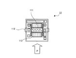
- FIG. 6 is a top view showing a schematic configuration of the flow rate detection unit 11 shown in FIG. 1
- FIG. 7 is a top view showing a schematic configuration of the physical property value detection unit 12 shown in FIG.
- the flow rate detection unit 11 includes a first thermopile (first temperature detection unit in the flow detection unit) 111 and a second thermopile (second temperature detection unit in the flow detection unit) 112 that detect the temperature of the fluid to be measured. And a micro heater 113 for heating the fluid to be measured.
- the microheater 113, the first temperature detection unit 111 in the flow rate detection unit, and the second temperature detection unit 112 in the flow rate detection unit are arranged side by side along the flow direction P of the measurement target fluid in the flow rate detection unit 11. .
- the shapes of the microheater 113, the first temperature detection unit 111 in the flow rate detection unit, and the second temperature detection unit 112 in the flow rate detection unit are substantially rectangular in a plan view, and the longitudinal direction of each of them is the flow direction of the fluid to be measured. Orthogonal to P.
- the first temperature detection unit 111 in the flow detection unit and the second temperature detection unit 112 in the flow detection unit have the first temperature detection unit 111 in the flow detection unit arranged upstream of the microheater 113 and the second temperature in the flow detection unit downstream.
- a detector 112 is arranged to detect the temperature at a symmetrical position with the micro heater 113 in between.
- the physical property value detection unit internal heating unit 123, the physical property value detection unit first temperature detection unit 121, and the physical property value detection unit second temperature detection unit 122 are substantially rectangular in a plan view, and the longitudinal direction of each is Along the flow direction Q of the fluid to be measured.
- the physical property value detection unit internal first temperature detection unit 121 and the physical property value detection unit internal temperature detection unit 122 are arranged symmetrically with the physical property value detection unit internal heating unit 123 interposed therebetween, and the physical property value detection unit internal heating unit 123. The temperature of the symmetrical position on both sides of the is detected.
- the physical property value detection unit first temperature detection unit 121, the physical property value detection unit internal heating unit 123, and the physical property value detection unit internal temperature second detection unit 122 are in this order orthogonal to the flow direction of the measurement target fluid.
- the physical property value detection unit internal heating unit 123 covers the measurement target fluid in a wide range over the flow direction of the measurement target fluid. Can be heated. For this reason, even if the temperature distribution is biased to the downstream side due to the flow of the measurement target fluid, the output characteristics of the first temperature detection unit 121 in the physical property value detection unit and the second temperature detection unit 122 in the physical property value detection unit are changed. Can be reduced. Therefore, the influence of the temperature distribution change due to the flow of the measurement target fluid can be reduced, the influence of the change of the temperature distribution due to the flow of the measurement target fluid can be reduced, and the detection accuracy by the physical property value detection unit 12 can be improved. .
- the first temperature detection in the physical property value detection unit since the longitudinal directions of the first temperature detection unit 121 in the physical property value detection unit 121 and the second temperature detection unit 122 in the physical property value detection unit are arranged along the flow direction of the fluid to be measured, the first temperature detection in the physical property value detection unit.
- the unit 121 and the physical property value detection unit second temperature detection unit 122 can detect the temperature in a wide range over the flow direction of the measurement target fluid. For this reason, even if the temperature distribution is biased to the downstream side due to the flow of the measurement target fluid, the output characteristics of the first temperature detection unit 121 in the physical property value detection unit and the second temperature detection unit 122 in the physical property value detection unit are changed. Can be reduced. Therefore, the influence of the change in temperature distribution due to the flow of the fluid to be measured can be reduced, and the detection accuracy by the physical property value detection unit 12 can be improved.
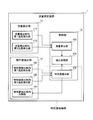
- FIG. 8 is a block diagram showing a functional configuration of the flow rate measuring device.
- the flow rate measuring device 1 includes a flow rate detection unit 11, a physical property value detection unit 12, and a control unit 13.
- the flow rate detection unit 11 includes a first temperature detection unit 111 in the flow detection unit and a second temperature detection unit 112 in the flow detection unit.
- the physical property value detection unit 12 includes a physical property value detection unit first temperature detection unit 121, a physical property value detection unit second temperature detection unit 122, and a physical property value detection unit internal heating unit 123.
- the flow rate detection unit 11 detects a value indicating the flow rate of the fluid to be measured based on the temperature detection signals output from the first temperature detection unit 111 in the flow rate detection unit and the second temperature detection unit 112 in the flow rate detection unit. Specifically, the flow rate detection unit 11 calculates a difference between the temperature detection signal output from the first temperature detection unit 111 in the flow rate detection unit and the temperature detection signal output from the second temperature detection unit 112 in the flow rate detection unit. Based on the difference, a value indicating the flow rate of the fluid to be measured is obtained. Then, the flow rate detection unit 11 outputs a value indicating the flow rate to the control unit 13.
- the physical property value detection unit 12 outputs the temperature detection signals output from the first temperature detection unit 121 in the physical property value detection unit and the second temperature detection unit 122 in the physical property value detection unit to the flow rate calculation unit 133. Specifically, the physical property value detection unit 12 obtains an average value of the temperature detection signals output from the first physical property detection unit first temperature detection unit 121 and the second physical property value detection unit second temperature detection unit 122. Moreover, the physical property value detection part internal heating part 123 changes temperature according to control by the control part 13, for example. Thereby, the first temperature detection unit 121 in the physical property value detection unit 121 and the second temperature detection unit 122 in the physical property value detection unit can obtain the output values before and after the temperature change of the heating unit 123 in the physical property value detection unit. The physical property value detection unit 12 outputs the acquired output value to the control unit 13.
- the control unit 13 includes a correction processing unit 131, a characteristic value calculation unit 132, and a flow rate calculation unit 133.
- the flow rate calculation unit 133 calculates the flow rate of the measurement target fluid based on the detection value of the flow rate detection unit 11.
- the characteristic value calculation unit 132 calculates a characteristic value based on the detection value of the physical property value detection unit 12. Specifically, the characteristic value calculation unit 132 changes the temperature of the micro heater of the physical property value detection unit 12, and multiplies the temperature difference of the fluid to be measured detected by the thermopile before and after the change by a predetermined coefficient to obtain the characteristic value. Is calculated.
- the correction processing unit 131 corrects the flow rate calculated by the flow rate calculation unit 133 using the characteristic value.
- the physical property value detection unit 12 and the characteristic value calculation unit 132 are also collectively referred to as a characteristic value acquisition unit.
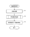
- FIG. 9 is a process flowchart showing an example of the flow rate measurement process.
- the flow rate detection unit 11 outputs temperature detection signals from the first temperature detection unit in the flow rate detection unit and the second temperature detection unit 112 in the flow rate detection unit, and the flow rate calculation unit 133 has two temperature detection signals. Based on the above, the flow rate of the fluid to be measured is calculated (FIG. 9: S1).
- the physical property value detection unit 12 executes a characteristic value acquisition process (S2). Details of the characteristic value acquisition processing will be described with reference to FIG.
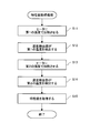
- FIG. 10 is a process flow diagram showing an example of the characteristic value acquisition process.
- the characteristic value calculation unit 132 of the control unit 13 causes the physical property value detection unit internal heating unit 123 of the physical property value detection unit 12 to heat at the first temperature (FIG. 10: S11). Then, the physical property value detection unit first temperature detection unit 121 and the physical property value detection unit second temperature detection unit 122 of the physical property value detection unit 12 detect the first temperature (S12). This step may be performed based on control by the control unit 13, for example.
- the speed of heat transmitted through the fluid to be measured is determined by physical property values such as thermal conductivity, thermal diffusivity, and specific heat.
- the thermal conductivity can be obtained by detecting a temperature difference between the physical property value detection unit internal heating unit 123, the physical property value detection unit first temperature detection unit 121, and the physical property value detection unit internal second temperature detection unit 122. .
- measurement is performed by the first physical property value detection unit 121 and the second physical property detection unit second temperature detection unit 122 arranged in a direction orthogonal to the flow direction of the measurement target fluid. The temperature of the target fluid is detected.
- the characteristic value calculation unit 132 of the control unit 13 causes the physical property value detection unit internal heating unit 123 of the physical property value detection unit 12 to heat at the second temperature (S13). Thereafter, the physical property value detection unit first temperature detection unit 121 and the physical property value detection unit second temperature detection unit 122 of the physical property value detection unit 12 detect the second temperature (S14). This step may also be performed based on control by the control unit 13, for example. In this manner, values indicating the temperatures detected by the first physical property value detection unit 121 and the second physical property detection unit temperature detector 122 are obtained before and after the temperature change of the physical property value detection unit heating unit 123.
- the characteristic value calculation unit 132 calculates the characteristic value using the detected temperature (S15).
- the sensor sensitivity ratio is obtained.
- the sensor sensitivity ratio is a ratio of a sensor output value when a predetermined gas is flowed to a sensor output value when a reference gas is flowed, and is a characteristic value representing a thermal diffusivity.
- the thermal diffusivity of the fluid to be measured can be detected by using the temperature change ( ⁇ T) detected by the heat pile when the temperature of the heater is changed.
- the flow rate output from the thermal flow sensor has a correlation with the thermal diffusivity. Therefore, according to the flow rate correction process according to the present embodiment, any gas can be corrected appropriately. That is, it is possible to improve the accuracy of flow rate measurement for fluids to be measured having different thermal diffusivities.
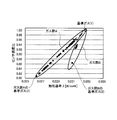
- FIG. 11 is a graph showing the sensor sensitivity ratio on the vertical axis and the thermal conductivity on the horizontal axis.
- the thermal conductivity as a physical property value is merely obtained. It is not determined which sensor sensitivity ratio should be used for correction. That is, in the method of performing correction using one set of the heating temperature of the microheater and the detected temperature of the thermopile, correction is performed based on two or more reference gases belonging to a predetermined gas group. Proper correction could not be performed.
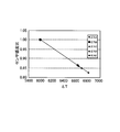
- FIG. 12 is a graph showing the sensor sensitivity ratio on the vertical axis and ⁇ T on the horizontal axis.
- the sensor sensitivity ratio and ⁇ T are approximated in a straight line. Therefore, in the present embodiment, correction can be performed for a gas group whose thermal diffusivity is unknown.
- the configuration in which the flow sensor of the flow rate measuring device 1 uses the fluid in the main flow path portion 2 as a measurement target is shown, but the present invention is not limited to such an example.
- the flow sensor of the flow rate measuring device 1 may use the fluid in the sub-flow path branched from the main flow path portion 2 as a measurement target.
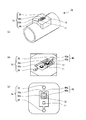
- FIG. 13 (a) is an exploded perspective view showing the flow rate measuring device 1 according to the present embodiment
- FIG. 13 (b) is a perspective view showing the flow rate measuring device 1 shown in FIG. 13 (a).
- the flow rate measuring device 1 according to the modification includes a main flow path portion 2, a sub flow path portion 3, a seal 4, a circuit board 5, and a cover 6. ing.
- the main channel portion 2 is a tubular member penetrating in the longitudinal direction.
- An inlet (first inlet) 34 is formed on the upstream side with respect to the flow direction O of the measurement target fluid, and an outlet (first outlet) 35 is formed on the downstream side on the inner peripheral surface of the main flow path portion 2. Is formed.
- the axial length of the main channel portion 2 is about 50 mm
- the diameter of the inner peripheral surface is about 20 mm
- the outer diameter of the main channel portion 2 is about 24 mm.
- the secondary flow path part 3 is provided on the main flow path part 2, and the secondary flow path is formed in the inside and upper surface.
- One end of the sub-flow channel portion 3 communicates with the inflow port 34A, and the other end communicates with the outflow port 35A.
- the sub-flow channel unit 3 is composed of an inflow channel 34, a physical property value detection channel 32, a flow rate detection channel 33, and an outflow channel 35.
- the inflow flow path 34 is a flow path for allowing the measurement target fluid flowing through the main flow path portion 2 to flow into the physical property value detection flow path 32 and the flow rate detection flow path 33.
- the inflow channel 34 is formed through the sub-channel unit 3 in a direction perpendicular to the main channel unit 2, one end communicating with the inflow port 34 ⁇ / b> A, and the other end on the upper surface of the main channel unit 2. It opens and communicates with the physical property value detection flow path 32 and the flow rate detection flow path 33. Thereby, a part of the fluid to be measured flowing through the main flow path portion 2 can be divided into the physical property value detection flow path 32 and the flow rate detection flow path 33 via the inflow flow path 34.
- the physical property value detection flow path 32 is a flow path formed in the upper surface of the sub flow path section 3 and extending in a direction parallel to the main flow path section 2 and having a substantially U-shaped longitudinal section.
- the physical property value detection unit 12 for detecting the physical property value of the measurement target fluid is disposed in a portion extending in the longitudinal direction (a direction parallel to the main flow path portion 2).
- One end of the physical property value detection channel 32 communicates with the inflow port 34A through the inflow channel 34, and the other end communicates with the outflow port 35A through the outflow channel 35.
- the flow rate detection flow path 33 is a flow path formed in the upper surface of the sub flow path section 3 and extending in a direction parallel to the main flow path section 2 and having a substantially U-shaped longitudinal section.
- the flow rate detection flow path 33 is a flow rate detection flow path in which a flow rate detection unit 11 for detecting the flow rate of the fluid to be measured is arranged in a portion extending in the longitudinal direction (a direction parallel to the main flow path unit 2). 33.
- One end of the flow rate detection channel 33 communicates with the inflow port 34A via the inflow channel 34, and the other end communicates with the outflow port 35A via the outflow channel 35.
- the physical property value detection unit 12 and the flow rate detection unit 11 and the circuit board 5 are shown in a separated state.
- the physical property value detection unit 12 and the flow rate detection unit 11 are It is arranged in the physical property value detection flow path 32 or the flow rate detection flow path 33 in a state of being mounted on the substrate 5.
- the outflow channel 35 is a channel for allowing the measurement target fluid that has passed through the physical property value detection channel 32 and the flow rate detection channel 33 to flow out to the main channel unit 2.
- the outflow channel 35 is formed through the sub-channel unit 3 in a direction perpendicular to the main channel unit 2, with one end communicating with the outflow port 35 ⁇ / b> A and the other end on the upper surface of the main channel unit 2. It opens and communicates with the physical property value detection flow path 32 and the flow rate detection flow path 33. As a result, the fluid to be measured that has passed through the physical property value detection flow path 32 and the flow rate detection flow path 33 can flow out to the main flow path portion 2 via the outflow flow path 35.
- the physical property value detection unit 12 and the flow rate detection unit 11 are connected to the temperature detection flow channel 32 and the flow rate detection flow channel 33 by dividing the fluid to be measured that has flowed from the same inlet 34A into the physical property value detection flow channel 32 and the flow rate detection flow channel 33.
- the physical property value or the flow rate can be detected based on the measurement target fluid having the same conditions such as concentration. Therefore, the measurement accuracy of the flow rate measuring device 1 can be improved.
- the circuit board 5 is arranged after the seal 4 is fitted into the sub-flow channel part 3, and the circuit board 5 is fixed to the sub-flow channel part 3 by the cover 6, thereby Airtightness inside the road portion 3 is ensured.
- FIG. 14 is a perspective view showing the auxiliary flow path portion 3 shown in FIG.
- the physical property value detection channel 32 has a substantially U-shaped one end communicating with the inflow channel 34 and the other end communicating with the outflow channel 35.
- the flow rate detection flow path 33 has a substantially U-shaped one end communicating with the inflow flow path 34 and the other end communicating with the outflow flow path 35.
- both end portions of the physical property value detection flow path 32 and the flow rate detection flow path 33 are also in communication with each other, and the physical property value detection flow path 32 and the flow rate detection flow path 33 are arranged on the upper surface of the sub flow path portion 3. A rectangular flow path is formed.
- the physical property value detection flow path 32 and the flow rate detection flow path 33 are both square when viewed from the direction perpendicular to the upper surface of the sub flow path portion 3.
- 34 and the outflow passage 35 are respectively formed at target positions.
- the length of one side of the physical property value detection channel 32 and the flow rate detection channel 33 is about 4 mm.
- the width of the physical property value detection flow path 32 matches the width of the physical property value detection flow path 32. You may let them.
- the portion extending in the longitudinal direction of the physical property value detection channel 32 is formed in a linear shape. The same applies to the flow rate detection flow path 33.
- FIG. 15A is a top view showing a schematic configuration of the physical property value detection unit 12 shown in FIG. 13, and FIG. 15B is a top view showing a schematic configuration of the flow rate detection unit 11 shown in FIG. It is.
- the physical property value detection flow path 32 and the flow rate detection flow path 33 have different widths of flow paths extending in the longitudinal direction.
- the width of the flow path in which the physical property value detection unit 12 is disposed is narrower than the width of the flow path in which the flow rate detection unit 11 of the flow rate detection flow path 33 is disposed.
- the flow rates of the measurement target fluid divided into the physical property value detection channel 32 and the flow rate detection channel 33 are individually controlled.
- FIG. 16 is a schematic diagram for explaining the flow rate of the measurement target fluid that is divided into the physical property value detection flow path 32 and the flow rate detection flow path 33 shown in FIG.
- the measurement target fluid of the flow rate P is divided into the physical property value detection flow path 32, and the measurement target fluid of the flow rate Q flows through the flow rate detection flow path 33.
- the widths of the physical property value detection flow path 32 and the flow rate detection flow path 33 are set.
- the values of the flow rate P and the flow rate Q vary depending on the flow rate of the fluid to be measured flowing through the main flow path unit 2. However, in a normal use mode, the flow rate P is a value within the detection range of the physical property value detection unit 12.
- the widths of the physical property value detection channel 32 and the flow rate detection channel 33 are set so that the flow rate Q becomes a value within the detection range of the flow rate detection unit 11.
- the flow rate of the measurement target fluid divided into the physical property value detection flow path 32 and the flow rate detection flow path 33 can be individually controlled by adjusting the respective widths. is there. For this reason, the flow rate of the measurement target fluid flowing through the physical property value detection flow path 32 is controlled according to the detection range of the physical property value detection unit 12, and flows through the flow rate detection flow channel 33 according to the detection range of the flow rate detection unit 11. The flow rate of the fluid to be measured can be controlled.
- the physical property value detection unit 12 can detect the physical property value of the fluid to be measured at an optimum flow rate according to the specific detection range, the detection accuracy of the physical property value detection unit 12 can be increased.
- the flow rate detection unit 11 can detect the flow rate of the fluid to be measured at an optimum flow rate according to the specific detection range, and thus the detection accuracy of the flow rate detection unit 11 can be increased.
- the configuration in which the physical property value detection flow path 32 and the flow rate detection flow path 33 are both formed in a substantially U shape has been described. It is not limited to this. If the physical property value detection flow path 32 and the flow rate detection flow path 33 are set to a width in which the flow rate of the fluid to be measured passing through the physical property value detection flow path 32 and the flow rate detection flow path 33 can be controlled, The shape is not particularly limited.
- the physical property value detection flow path 32 may be formed in a straight line, and the flow rate detection flow path 33 may be formed in a substantially U-shape.
- the physical property value detection flow path 32 is directed from the direction perpendicular to the direction in which the fluid to be measured flows into the flow rate detection flow path 33.
- the physical property value detection flow path 32 may be formed so that the fluid to be measured flows.
- the physical property value detection unit 12 and the flow rate detection unit 11 are mounted on the circuit board 5 in the manufacturing process of the flow measurement device 1.
- the process to do can be simplified.
- the physical property value detection unit 12 includes a physical property value detection unit heating unit 123 that heats the measurement target fluid, and a physical property value detection that detects the temperature of the measurement target fluid.
- the first internal temperature detection unit 121 and the second internal temperature detection unit 122 in the physical property value detection unit 122, and the first internal temperature detection unit 121 in the physical property value detection unit and the second internal temperature detection unit 122 in the physical property value detection unit are heated in the physical property value detection unit.
- FIG. 18 is a top view illustrating a schematic configuration of a modified example of the physical property value detection unit 12 illustrated in FIG. As shown in FIG. 18, the physical property value detection unit second temperature detection unit 122 is omitted, and the physical property value detection unit internal heating unit 123 and the physical property value detection unit first temperature detection unit 121 include the physical property value detection unit 12 a. May be configured.
- the physical property value detection unit 12a may be realized by arranging the physical property value detection unit internal heating unit and the physical property value detection unit first temperature detection unit side by side in a direction orthogonal to the flow direction of the measurement target fluid. .
- FIG. 19 (a) is a perspective view showing a flow rate measuring device 1a according to this modification
- FIG. 19 (b) is a cross-sectional view showing the flow rate measuring device 1a shown in FIG. 19 (a).
- 19 (c) is a top view showing the sub-flow channel portion 3a shown in FIG. 19 (a).
- an opening 37A is formed between the inlet 34A and the outlet 35A on the inner peripheral surface of the main flow path portion 2a. ing.
- a cellular flow rate detection flow path 37a in which the flow rate detection unit 11 is arranged is formed inside the sub flow path part 3a, and the flow rate detection flow path 37a communicates with the opening 37A. For this reason, the fluid to be measured that flows through the main flow path portion 2a flows into the flow rate detection flow path 37a via the opening 37A, and the flow rate detection section 11 detects the flow rate.
- the sub-flow channel portion 3a includes an inflow channel 34, a physical property value detection channel 32, and an outflow channel 35.
- the physical property value detection channel 32 extends in the longitudinal direction.
- the flow path has a physical property value detection flow path 32 in which the physical property value detection unit 12 for detecting the physical property value of the fluid to be measured is arranged.
- the physical property value detection unit 12 is disposed in the sub-flow channel unit 3a, and the flow rate detection unit 11 is disposed in the main flow channel unit 2a. For this reason, in the flow measuring device 1a, it is possible to control the flow according to the detection range of the physical property value detection unit 12.
- the flow rate measuring device 1a that can reduce the change in the output characteristics due to the change in the physical properties of the measurement target fluid and can measure the flow rate of the measurement target fluid with high accuracy.
- the flow measurement device according to this modification is different from the flow measurement device described above in that it has two independent sub-channels.
- FIG. 20 (a) is a perspective view showing the flow rate measuring device 1b according to the present embodiment
- FIG. 20 (b) is a top view showing the sub-flow channel section 3 shown in FIG. 20 (a).
- the sub-flow channel portion 3b has two sub-flow channel portions formed inside and on the upper surface thereof.
- the first sub-flow channel portion includes an inflow channel 34b, a physical property value detection channel 32b, and an outflow channel 35b.
- the physical property value detection channel 32b has a longitudinal direction.
- a physical property value detection unit 12 for detecting the physical property value of the fluid to be measured is disposed in the extending flow path.
- the second sub-channel portion is composed of an inflow channel 34B, a flow rate detection channel 33B, and an outflow channel 35B, and extends in the longitudinal direction in the flow rate detection channel 33B.
- a flow rate detection unit 11 for detecting the flow rate of the measurement target fluid is disposed in the flow path.
- the sub flow channel portion 3b has two independent sub flow channels, the physical property value detection unit 12 is disposed in the first sub flow channel unit, and the flow rate detection unit 11 is provided. Is disposed in the second sub-flow channel section. For this reason, according to the flow measuring device 1b, it is possible to control individually the flow volume according to the detection range of the physical property value detection part 12 and the flow volume detection part 11.
- the flow rate measuring device 1b that can reduce the change in the output characteristics due to the change in the physical properties of the measurement target fluid and can measure the flow rate of the measurement target fluid with high accuracy.
- the flow measurement device is different from the above flow measurement device in that the physical property value detection flow path is formed in the flow detection flow path.
- FIG. 21 (a) is a perspective view showing a flow rate measuring device 1c according to the present embodiment
- FIG. 21 (b) is a perspective view showing a sub flow channel portion 3c shown in FIG. 21 (a)
- FIG.21 (c) is a top view which shows the subchannel part 3c shown by Fig.21 (a).
- the sub-flow channel portion 3c includes the inflow channel 34, the physical property value detection channel 32c, and the flow rate detection flow.
- the passage 33c and the outflow passage 35 are configured.
- the physical property value detection flow channel 32c is formed in the flow rate detection flow channel 33c, and the flow rate detection unit 11 is arranged on the upstream side with respect to the flow direction of the measurement target fluid.
- the physical property value detector 12 is disposed on the side.
- the physical property value detection channel 32c is partitioned from the flow rate detection channel 33c by a flow rate control member 40 for controlling the flow rate of the fluid to be measured. Is placed inside.
- the flow rate control member 40 is for controlling the flow rate of the fluid to be measured that passes through the physical property value detection channel 32c, and includes a first side wall portion 40a and a second side wall portion 40b.
- the first side wall portion 40a and the second side wall portion 40b are both substantially U-shaped plate-like members, and are arranged at a predetermined interval in a state where the respective end portions are opposed to each other.
- the flow rate of the fluid to be measured that passes through the flow rate control member 40, that is, the physical property value detection channel 32c is adjusted. Can do.
- the secondary flow path portion 3c includes the flow rate control member 40, and the physical property value detection flow path 32c is provided inside the flow rate control member 40. It is possible to provide the physical property value detection channel 32c at any position. In addition, by providing the flow rate control member 40, the flow rate of the fluid to be measured that passes through the physical property value detection channel 32c can be easily controlled.
- the flow rates corresponding to the detection ranges of the physical property value detection unit 12 and the flow rate detection unit 11 are individually set. It is possible to control.
- the flow rate measuring device 1c that can measure the flow rate of the measurement target fluid with high accuracy by reducing the change in the output characteristic due to the change in the physical property of the measurement target fluid.
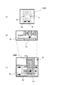
- FIGS. 22A to 22C are diagrams showing an example of a multistage shunt type according to another modification.
- FIG. 22 (c) shows the connection location of the main flow path portion 2d and the flow rate measuring device 1d.
- FIG.22 (b) is the figure which expanded the location shown with the broken-line rectangle in FIG.22 (c).
- FIG. 22A is a cross-sectional view taken along the line AA of the unit 1000 in FIG.
- a sub-flow channel portion 3d that is thinner (smaller in cross-sectional area) than the main flow channel portion 2d is provided along the flow direction of the main flow channel portion 2. ing.
- the sub-flow channel portion 3d branches into a main flow channel 2e penetrating along the main flow channel portion 2d and a sub-flow channel portion 3e connected substantially perpendicular to the sub-flow channel portion 3d. And as shown to Fig.22 (a), the subchannel part 3e is divided into the subchannel part 3f in which the flow volume detection part 11 was provided, and the subchannel part 3g in which the physical-property value detection part 12 was provided. Branch.
- the flow rate can be measured by the small flow rate measuring device 1d regardless of the flow rate of the main flow channel portion 2d (that is, the thickness (cross-sectional area) of the main flow channel portion 2d). Further, according to the modified example having the above-described sub-flow channel, it is possible to suppress the intrusion of dust into the sensor chip and improve the measurement accuracy. However, as in the modified example shown in FIG. By adopting, the amount of dust intrusion can be further reduced.
- a component having a sub-flow channel portion 3f provided with the flow rate detection unit 11 and a sub-flow channel unit 3g provided with the physical property detection unit 12 is detachable. It may be formed as a simple part. If it does in this way, the parts which can be attached to main flow path part 2 of various flow volume and shapes can be provided, and cost can be reduced.
Landscapes
- Physics & Mathematics (AREA)
- General Physics & Mathematics (AREA)
- Fluid Mechanics (AREA)
- Analytical Chemistry (AREA)
- Life Sciences & Earth Sciences (AREA)
- Chemical & Material Sciences (AREA)
- Health & Medical Sciences (AREA)
- Biochemistry (AREA)
- General Health & Medical Sciences (AREA)
- Immunology (AREA)
- Pathology (AREA)
- Engineering & Computer Science (AREA)
- Aviation & Aerospace Engineering (AREA)
- Measuring Volume Flow (AREA)
- Investigating Or Analyzing Materials Using Thermal Means (AREA)
Abstract
流量測定装置は、主流路を流れる測定対象流体の流量を検出するための流量検出部と、測定対象流体を加熱する加熱部および測定対象流体の温度を検出する温度検出部を有し、測定対象流体の特性値を取得するための特性値取得部と、前記特性値取得部によって取得された測定対象流体の特性値を用いて、前記流量検出部から出力された検出信号に基づいて算出された測定対象流体の流量を補正する流量補正部とを備え、前記加熱部および前記温度検出部は、測定対象流体の流れ方向と直交する方向に並んで配置されており、前記特性値取得部は、前記加熱部の温度を変化させた前後における、前記温度検出部により検出された前記測定対象流体の温度の差により、前記特性値を取得する。
Description
本発明は、流量測定装置、流量の測定方法及び流量測定プログラムに関する。
従来、加熱部および温度検出部を備え、測定対象流体の流量を測定する流量測定装置が提案されている。例えば、測定対象流体の物性変化による出力特性の変化を低減させるため、測定対象流体の物性値を検出するための物性値検出部を備える流量測定装置も提案されている(特許文献1)。具体的には、マイクロヒータとサーモパイルとの温度差を検出することにより熱伝導率(熱拡散定数)を求め、センサによって測定された流量を熱伝導率に基づいて補正する。
従来、マイクロヒータとサーモパイルとの温度差に基づいて熱伝導率を求め、熱伝導率を用いて測定対象流体の流量を補正するという技術が提案されていた。ここで、いわゆる熱式のフローセンサを用いる場合、測定対象流体の熱拡散率もセンサの出力に影響する。すなわち、従来技術では、気体によって流量を適切に補正できない場合があった。
本発明は、上記のような問題に鑑みてなされたものであり、熱拡散率が異なる測定対象流体について、流量の測定の精度を向上させることを目的とする。
本発明に係る流量測定装置は、主流路を流れる測定対象流体の流量を検出するための流量検出部と、測定対象流体を加熱する加熱部および測定対象流体の温度を検出する温度検出部を有し、測定対象流体の特性値を取得するための特性値取得部と、前記特性値取得部によって取得された測定対象流体の特性値を用いて、前記流量検出部から出力された検出信号に基づいて算出された測定対象流体の流量を補正する流量補正部とを備え、前記加熱部および前記温度検出部は、測定対象流体の流れ方向と直交する方向に並んで配置されており、前記特性値取得部は、前記加熱部の温度を変化させた前後における、前記温度検出部により検出された前記測定対象流体の温度の差により、前記特性値を取得する。
加熱部の温度を変化させた前後における、温度検出部により検出された測定対象流体の温度の差により取得した特性値を用いれば、測定対象流体の熱伝導率や比熱、粘度によって変わる熱拡散率に応じた補正を行うことができる。したがって、熱拡散率が異なる測定対象流体について、流量の測定の精度を向上させることができる。
また、特性値は、加熱部の温度を変化させた前後における、温度検出部により検出された測定対象流体の温度の差に、所定の係数を乗じた値であり、流量補正部は、流量検出部から出力された検出信号に、特性値を乗じることで、測定対象流体の流量を補正するようにしてもよい。具体的には、このような値を特性値として用いることができる。
また、一端が主流路内に開口した第1流入口に連通し、且つ、他端が主流路内に開口した第1流出口に連通することで主流路から分流されるとともに、特性値取得部の前記温度検出部が配置された特性値検出流路を有する副流路部をさらに備え、流量検出部は、特性値検出流路とは異なる位置に配置されるようにしてもよい。副流路部を設けることで、主流路の大きさや流量にかかわらず、流量を測定できる装置を提供することができる。また、流量検出部や特性値取得部の前記温度検出部へのダストの侵入を抑制できる。
また、特性値取得部の前記温度検出部および流量検出部は、主流路または、副流路部を構成する部材に脱着可能に設けられた流量検出部材に設けられるようにしてもよい。このようにすれば、様々な流量や形状の主流路部2に対して取り付け可能な部品を提供することができ、コストを低減できる。
また、副流路部は、流量検出部が配置された流量検出流路と、一端が主流路内に開口した第1流入口に連通し、且つ、他端が主流路内に開口した第1流出口に連通することで副流路部から分流された第一副流路部と、一端が第一副流路部に開口した第2流入口に連通し、且つ、他端が第一副流路部内に開口した第2流出口に連通することで第一副流路部から分流された第二副流路部とを有し、流量検出流路及び特性値検出流路はともに、一端が第二副流路部に開口した第3流入口に連通し、且つ、他端が第二副流路部内に開口した第3流出口に連通することで第二副流路部からさらに分流されることで形成されるようにしてもよい。このように3段階の分流構造を採用すれば、流量検出部や特性値取得部の前記温度検出部へのダストの侵入量をさらに低減することができる。
また、副流路部は、流量検出部が配置された流量検出流路をさらに有しており、流量検出流路は、一端が第1流入口に連通し、且つ、他端が第1流出口に連通しており、第1流入口から流入した測定対象流体を、特性値検出流路および流量検出流路に分流させるようにしてもよい。具体的な分流構造としては、このような構成を採用することもできる。
また、副流路部は、流量検出部が配置された流量検出流路をさらに有しており、特性値検出流路は、流量検出流路内に設けられており、流量検出流路内を流れる測定対象流体の一部を特性値検出流路に流入させるようにしてもよい。具体的な分流構造としては、このような構成を採用することもできる。
また、副流路部は、流量検出部が配置された流量検出流路をさらに有しており、流量検出流路は、一端が主流路内に開口した第4流入口に連通し、且つ、他端が主流路内に開口した第4流出口に連通するようにしてもよい。具体的な分流構造としては、このような構成を採用することもできる。
また、流量検出部は、主流路に配置されるようにしてもよい。このように、流量検出部が主流路の流体を測定対象とする構成にしてもよい。
また、加熱部は、当該加熱部の長手方向が測定対象流体の流れ方向に沿って配置されるようにしてもよい。このようにすれば、加熱部は、測定対象流体の流れ方向に亘って広範囲に測定対象流体を加熱することが可能となる。
また、温度検出部は、当該温度検出部の長手方向が測定対象流体の流れ方向に沿って配置されるようにしてもよい。このようにすれば、温度検出部は、測定対象流体の流れ方向に亘って広範囲に温度を検出することが可能となる。
また、副流路部は、流量検出部が配置された流量検出流路をさらに有しており、流量検出流路と特性値検出流路は、副流路部または該副流路部から分流された流路に、回路基板を測定対象流体の流れ方向に平行に配置して副流路部または該副流路部を分流することで形成され、流量検出部及び特性値取得部の前記温度検出部は、それぞれ、回路基板上の一面と、反対面に設けられるようにしてもよい。具体的な分流構造としては、このような構成を採用することもできる。
なお、課題を解決するための手段に記載の内容は、本発明の課題や技術的思想を逸脱しない範囲で可能な限り組み合わせることができる。また、課題を解決するための手段に示した流量測定装置の内容は、方法又はプロセッサやマイクロコントローラ等に実行させるプログラムとして提供することができる。
熱拡散率が異なる測定対象流体について、流量の測定の精度を向上させることができる。
以下、本発明の実施形態に係る流量測定装置について、図面を用いて説明する。なお、以下に示す実施形態は、流量測定装置の一例であり、本発明に係る流量測定装置は、以下の構成には限定されない。
<装置構成>
図1は、本実施形態に係る流量測定装置の装置構成を示す斜視図である。図2は、流量測定装置の縦断面図である。図3は、流量測定装置の横断面図である。流量測定装置は、例えばガスメータや燃焼機器、自動車等の内燃機関、燃料電池に組み込まれ、流路を通過する気体の量を測定する。なお、図1の破線の矢印は、流体の流れる方向を例示している。図1~図3に示すように、本実施形態では、流量測定装置1は主流路部2の内部に設けられる。また、流量測定装置1は、流量検出部11と、物性値検出部(「温度検出部」とも呼ぶ)12と、制御部13とを備える。流量検出部11及び物性値検出部12は、マイクロヒータが形成する加熱部とサーモパイルが形成する温度検出部とを含む、いわゆる熱式のフローセンサである。
図1は、本実施形態に係る流量測定装置の装置構成を示す斜視図である。図2は、流量測定装置の縦断面図である。図3は、流量測定装置の横断面図である。流量測定装置は、例えばガスメータや燃焼機器、自動車等の内燃機関、燃料電池に組み込まれ、流路を通過する気体の量を測定する。なお、図1の破線の矢印は、流体の流れる方向を例示している。図1~図3に示すように、本実施形態では、流量測定装置1は主流路部2の内部に設けられる。また、流量測定装置1は、流量検出部11と、物性値検出部(「温度検出部」とも呼ぶ)12と、制御部13とを備える。流量検出部11及び物性値検出部12は、マイクロヒータが形成する加熱部とサーモパイルが形成する温度検出部とを含む、いわゆる熱式のフローセンサである。
図4は、流量検出部及び物性値取得部に用いられるセンサ素子の一例を示す斜視図である。また、図5は、センサ素子の仕組みを説明するための断面図である。センサ素子100は、マイクロヒータ(加熱部)101と、マイクロヒータ101を挟んで両側に設けられたサーモパイル(温度検出部)102とを備える。これらの上下には絶縁薄膜が形成され、シリコン基台上に設けられている。また、マイクロヒータ101及びサーモパイル102の下方のシリコン基台には、キャビティ(空洞)が設けられている。マイクロヒータ101は、例えばポリシリコンで形成された抵抗体である。図5は、破線の楕円によって、マイクロヒータ101が発熱した場合の温度分布を模式的に示している。なお、破線が太いほど温度が高いものとする。空気の流れがない場合、図5の上段(1)に示すようにマイクロヒータ101の両側の温度分布はほぼ均等になる。一方、例えば図5の下段(2)において破線の矢印で示す方向に空気が流れた場合、周囲の空気が移動するため、マイクロヒータ101の風上側よりも風下側の方が、温度は高くなる。センサ素子は、このようなヒータ熱の分布の偏りを利用して、流量を示す値を出力する。
また、図1の制御部13は、マイクロコントローラ等の演算装置によって形成され、流量検出部11の出力に基づいて流量を算出したり、物性値検出部12の出力に基づいて所定の特性値を算出したり、特性値を用いて流量を補正したりする。
<流量検出部及び物性値取得部>
図6は、図1に示した流量検出部11の概略構成を示す上面図であり、図7は、図1に示した物性値検出部12の概略構成を示す上面図である。
図6に示すように、流量検出部11は、測定対象流体の温度を検出する第1サーモパイル(流量検出部内第1温度検出部)111および第2サーモパイル(流量検出部内第2温度検出部)112と、測定対象流体を加熱するマイクロヒータ113とを備えている。マイクロヒータ113と、流量検出部内第1温度検出部111および流量検出部内第2温度検出部112とは、流量検出部11内において、測定対象流体の流れ方向Pに沿って並んで配置されている。また、マイクロヒータ113、流量検出部内第1温度検出部111、および流量検出部内第2温度検出部112の形状は、平面視においてそれぞれ略矩形であり、各々の長手方向は測定対象流体の流れ方向Pと直交する。
流量検出部内第1温度検出部111および流量検出部内第2温度検出部112は、マイクロヒータ113の上流側に流量検出部内第1温度検出部111が配置され、下流側に流量検出部内第2温度検出部112が配置されて、マイクロヒータ113を挟んで対称な位置の温度を検出する。
流量測定装置1では、物性値検出部12および流量検出部11に、実質的に同一構造のセンサが用いられており、測定対象流体の流れ方向に対する配置角度を90°異ならせて配置されている。これにより、同一構造のセンサを物性値検出部12または流量検出部11として機能させることが可能となるため、流量測定装置1の製造コストを低減することができる。
一方、図7に示すように、物性値検出部12は、測定対象流体の温度を検出する第1サーモパイル(物性値検出部内第1温度検出部)121および第2サーモパイル(物性値検出部内第2温度検出部)122と、測定対象流体を加熱するマイクロヒータ(物性値検出部内加熱部)123とを備えている。物性値検出部内加熱部123と、物性値検出部内第1温度検出部121および物性値検出部内第2温度検出部122とは、物性値検出部12内において、測定対象流体の流れ方向Qと直交する方向に並んで配置されている。また、物性値検出部内加熱部123、物性値検出部内第1温度検出部121、および物性値検出部内第2温度検出部122の形状は、平面視においてそれぞれ略矩形であり、各々の長手方向は測定対象流体の流れ方向Qに沿っている。また、物性値検出部内第1温度検出部121および物性値検出部内第2温度検出部122は、物性値検出部内加熱部123を挟んで左右対称に配置されており、物性値検出部内加熱部123の両側の対称な位置の温度を検出する。
ここで、測定対象流体の流れによって温度分布は下流側に偏るため、流れ方向と直交する方向の温度分布の変化は、測定対象流体の流れ方向の温度分布の変化に比べて小さい。このため、物性値検出部内第1温度検出部121と、物性値検出部内加熱部123と、物性値検出部内第2温度検出部122とを、この順で測定対象流体の流れ方向と直交する方向に並べて配置することにより、温度分布の変化による物性値検出部内第1温度検出部121および物性値検出部内第2温度検出部122の出力特性の変化を低減することができる。したがって、測定対象流体の流れによる温度分布の変化の影響を低減して、物性値検出部12による検出精度を向上させることができる。
また、物性値検出部内加熱部123の長手方向が測定対象流体の流れ方向に沿って配置されているため、物性値検出部内加熱部123は測定対象流体の流れ方向に亘って広範囲に測定対象流体を加熱することが可能となる。このため、測定対象流体の流れによって温度分布が下流側に偏った場合であっても、物性値検出部内第1温度検出部121および物性値検出部内第2温度検出部122の出力特性の変化を低減することができる。したがって、測定対象流体の流れによる温度分布の変化の影響を低減して、測定対象流体の流れによる温度分布の変化の影響を低減して、物性値検出部12による検出精度を向上させることができる。
さらに、物性値検出部内第1温度検出部121および物性値検出部内第2温度検出部122の長手方向が測定対象流体の流れ方向に沿って配置されているため、物性値検出部内第1温度検出部121および物性値検出部内第2温度検出部122は測定対象流体の流れ方向に亘って広範囲に温度を検出することが可能となる。このため、測定対象流体の流れによって温度分布が下流側に偏った場合であっても、物性値検出部内第1温度検出部121および物性値検出部内第2温度検出部122の出力特性の変化を低減することができる。したがって、測定対象流体の流れによる温度分布の変化の影響を低減して、物性値検出部12による検出精度を向上させることができる。
<機能構成>
図8は、流量測定装置の機能構成を示すブロック図である。流量測定装置1は、流量検出部11と、物性値検出部12と、制御部13とを備えている。流量検出部11は、流量検出部内第1温度検出部111と、流量検出部内第2温度検出部112とを備える。物性値検出部12は、物性値検出部内第1温度検出部121と、物性値検出部内第2温度検出部122と、物性値検出部内加熱部123とを備える。
図8は、流量測定装置の機能構成を示すブロック図である。流量測定装置1は、流量検出部11と、物性値検出部12と、制御部13とを備えている。流量検出部11は、流量検出部内第1温度検出部111と、流量検出部内第2温度検出部112とを備える。物性値検出部12は、物性値検出部内第1温度検出部121と、物性値検出部内第2温度検出部122と、物性値検出部内加熱部123とを備える。
流量検出部11は、流量検出部内第1温度検出部111および流量検出部内第2温度検出部112から出力された温度検出信号に基づいて、測定対象流体の流量を示す値を検出する。具体的には、流量検出部11は、流量検出部内第1温度検出部111から出力された温度検出信号と流量検出部内第2温度検出部112から出力された温度検出信号との差分を算出し、差分に基づいて測定対象流体の流量を示す値を求める。そして、流量検出部11は、流量を示す値を制御部13に出力する。
物性値検出部12は、物性値検出部内第1温度検出部121および物性値検出部内第2温度検出部122から出力された温度検出信号を流量算出部133に出力する。具体的には、物性値検出部12は、物性値検出部内第1温度検出部121および物性値検出部内第2温度検出部122から出力された温度検出信号の平均値を求める。また、物性値検出部内加熱部123は、例えば制御部13による制御に応じて温度を変更する。これにより、物性値検出部内第1温度検出部121及び物性値検出部内第2温度検出部122は、物性値検出部内加熱部123の温度変化の前後における出力値を求めることができる。物性値検出部12は、取得した出力値を制御部13に出力する。
また、制御部13は、補正処理部131と、特性値算出部132と、流量算出部133とを含む。流量算出部133は、流量検出部11の検出値に基づいて測定対象流体の流量を算出する。特性値算出部132は、物性値検出部12の検出値に基づいて特性値を算出する。具体的には、特性値算出部132は、物性値検出部12のマイクロヒータの温度を変化させ、変化の前後においてサーモパイルが検出した測定対象流体の温度の差に所定の係数を乗じて特性値を算出する。補正処理部131は、特性値を用いて、流量算出部133が算出した流量を補正する。なお、物性値検出部12と特性値算出部132とを総称して特性値取得部とも呼ぶ。
<流量測定処理>
図9は、流量測定処理の一例を示す処理フロー図である。図9に示すように、流量検出部11は、流量検出部内第1温度検出部および流量検出部内第2温度検出部112から温度検出信号を出力し、流量算出部133は、2つの温度検出信号に基づいて測定対象流体の流量を算出する(図9:S1)。
図9は、流量測定処理の一例を示す処理フロー図である。図9に示すように、流量検出部11は、流量検出部内第1温度検出部および流量検出部内第2温度検出部112から温度検出信号を出力し、流量算出部133は、2つの温度検出信号に基づいて測定対象流体の流量を算出する(図9:S1)。
具体的には、流量検出部11は、流量検出部内第1温度検出部111から出力された温度検出信号と流量検出部内第2温度検出部112から出力された温度検出信号とを出力する。また、流量算出部133は、2つの温度検出信号の差分を算出し、差分に基づいて測定対象流体の流量を示す値を算出する。
なお、流量検出部内第1温度検出部111および流量検出部内第2温度検出部112から出力された温度検出信号に基づいて定対象流体の流量を算出する手法は、公知のものを用いることができる。流量検出部11は、算出した測定対象流体の流量を制御部13に出力する。
また、物性値検出部12は、特性値取得処理を実行する(S2)。特性値取得処理の詳細は、図10を用いて説明する。
図10は、特性値取得処理の一例を示す処理フロー図である。制御部13の特性値算出部132は、物性値検出部12の物性値検出部内加熱部123に、第1の温度で加熱させる(図10:S11)。その後、物性値検出部12の物性値検出部内第1温度検出部121及び物性値検出部内第2温度検出部122は、第1の温度を検出する(S12)。本ステップは、例えば制御部13による制御に基づいて行うようにしてもよい。測定対象流体を伝わる熱の速度は、熱伝導率、熱拡散率、比熱などの物性値によって決定される。また、物性値検出部内加熱部123と、物性値検出部内第1温度検出部121および物性値検出部内第2温度検出部122との温度差を検出することによって、熱伝導率を求めることができる。例えば、物性値検出部内加熱部123と、物性値検出部内第1温度検出部121および物性値検出部内第2温度検出部122との温度差が大きいほど、熱伝導率は小さくなる。このような性質を利用して、本ステップでは、測定対象流体の流れ方向と直交する方向に配置された物性値検出部内第1温度検出部121および物性値検出部内第2温度検出部122によって測定対象流体の温度を検出する。
次に、制御部13の特性値算出部132は、物性値検出部12の物性値検出部内加熱部123に、第2の温度で加熱させる(S13)。その後、物性値検出部12の物性値検出部内第1温度検出部121及び物性値検出部内第2温度検出部122は、第2の温度を検出する(S14)。本ステップも、例えば制御部13による制御に基づいて行うようにしてもよい。このようにして、物性値検出部内加熱部123の温度変化の前後において物性値検出部内第1温度検出部121及び物性値検出部内第2温度検出部122により検出された温度を示す値が取得される。
また、特性値算出部132は、検出された温度を用いて特性値を算出する(S15)。本ステップでは、センサ感度比を求める。センサ感度比とは、基準となる気体を流した場合のセンサ出力値に対する、所定の気体を流した場合のセンサ出力値の比であり、熱拡散率を表す特性値である。センサ感度比αは、下記の式(1)で求められる。
α = β × ΔT ・・・(1)
βは所定の係数である。また、ΔTは、物性値検出部内加熱部123の温度変化の前後において物性値検出部内第1温度検出部121及び物性値検出部内第2温度検出部122により出力された検出値の差分である。
α = β × ΔT ・・・(1)
βは所定の係数である。また、ΔTは、物性値検出部内加熱部123の温度変化の前後において物性値検出部内第1温度検出部121及び物性値検出部内第2温度検出部122により出力された検出値の差分である。
その後、図9の処理に戻り、制御部13は、特性値を用いて、流量算出部が算出した測定対象流体の流量を補正する(図9:S3)。具体的には、制御部13は、下記の式(2)を用いて、補正後の流量を算出する。
補正後の出力 = 流量算出部の出力 × α ・・・(2)
補正後の出力 = 流量算出部の出力 × α ・・・(2)
本実施形態では、ヒータの温度を変化させた際にヒートパイルで検出される温度の変化量(ΔT)を用いることで、測定対象流体の熱拡散率を検出することができるようになる。ここで、熱式のフローセンサが出力する流量は、熱拡散率と相関がある。したがって、本実施形態に係る流量の補正処理によれば、あらゆる気体について適切に補正できるようになる。すなわち、熱拡散率が異なる測定対象流体について、流量の測定の精度を向上させることができる。
図11は、縦軸にセンサ感度比、横軸に熱伝導率を示すグラフである。ここで、図11に示すように、例えば組成の異なる混合ガスのように熱伝導率以外の物性値が異なる複数のガス群が存在する場合、物性値としてある熱伝導率が求められただけではいずれのセンサ感度比を用いて補正すればよいのか定まらない。すなわち、マイクロヒータの加熱温度とサーモパイルの検知温度とを1組用いて補正を行う手法では、所定のガス群に属する2以上の基準ガスに基づいて補正を行っていたところ、複数のガス群について適切に補正を行うことはできなかった。
図12は、縦軸にセンサ感度比、横軸にΔTを示すグラフである。図11に示した、センサ感度比と熱伝導率とが一直線に近似されないガスについても、センサ感度比とΔTとは一直線に近似される。したがって、本実施形態では熱拡散率が未知のガス群についても補正を行うことができる。
<変形例>
上述した実施形態では、流量測定装置1のフローセンサが主流路部2内の流体を測定対象とする構成を示したが、このような例には限定されない。例えば、流量測定装置1のフローセンサは、主流路部2から分岐させた副流路内の流体を測定対象としてもよい。
上述した実施形態では、流量測定装置1のフローセンサが主流路部2内の流体を測定対象とする構成を示したが、このような例には限定されない。例えば、流量測定装置1のフローセンサは、主流路部2から分岐させた副流路内の流体を測定対象としてもよい。
図13(a)は、本実施形態に係る流量測定装置1を示す分解斜視図であり、図13(b)は、図13(a)に示される流量測定装置1を示す透視図である。図13(a)(b)に示すように、変形例に係る流量測定装置1は、主流路部2と、副流路部3と、シール4と、回路基板5と、カバー6とを備えている。
主流路部2は、長手方向に貫通した管状部材である。主流路部2の内周面には、測定対象流体の流れ方向Oに対して、上流側に流入口(第1流入口)34が形成され、下流側に流出口(第1流出口)35が形成されている。
なお、本実施形態では、主流路部2の軸方向の長さは約50mmであり、内周面の直径(主流路部2の内径)は約20mmであり、主流路部2の外径は約24mmである。
副流路部3は、主流路部2の上に設けられており、その内部および上面には、副流路が形成されている。副流路部3は、一端が流入口34Aに連通し、他端が流出口35Aに連通している。流量測定装置1では、副流路部3は、流入用流路34と、物性値検出用流路32と、流量検出用流路33と、流出用流路35とから構成されている。
流入用流路34は、主流路部2を流れる測定対象流体を流入させて、物性値検出用流路32および流量検出用流路33に分流させるための流路である。流入用流路34は、主流路部2と垂直な方向に、副流路部3を貫通して形成されており、一端が流入口34Aに連通し、他端は主流路部2の上面で開口して、物性値検出用流路32および流量検出用流路33に連通している。これにより、主流路部2を流れる測定対象流体の一部を、流入用流路34を介して、物性値検出用流路32および流量検出用流路33に分流させることができる。
物性値検出用流路32は、副流路部3の上面に形成された、主流路部2と平行な方向に延在する、縦断面が略コの字型の流路である。物性値検出用流路32は、長手方向(主流路部2と平行な方向)に延在する部分に、測定対象流体の物性値を検出するための物性値検出部12が配置されている。物性値検出用流路32の一端は、流入用流路34を介して流入口34Aに連通しており、他端は、流出用流路35を介して流出口35Aに連通している。
流量検出用流路33は、副流路部3の上面に形成された、主流路部2と平行な方向に延在する、縦断面が略コの字型の流路である。流量検出用流路33は、長手方向(主流路部2と平行な方向)に延在する部分に、測定対象流体の流量を検出するための流量検出部11が配置された流量検出用流路33を有している。流量検出用流路33の一端は、流入用流路34を介して流入口34Aに連通しており、他端は、流出用流路35を介して流出口35Aに連通している。
なお、図面では、説明の便宜上、物性値検出部12および流量検出部11と、回路基板5とが分離された状態で図示しているが、物性値検出部12および流量検出部11は、回路基板5に実装された状態で物性値検出用流路32または流量検出用流路33に配置されている。
流出用流路35は、物性値検出用流路32および流量検出用流路33を通過した測定対象流体を、主流路部2に流出させるための流路である。流出用流路35は、主流路部2と垂直な方向に、副流路部3を貫通して形成されており、一端が流出口35Aに連通し、他端は主流路部2の上面で開口して、物性値検出用流路32および流量検出用流路33に連通している。これにより、物性値検出用流路32および流量検出用流路33を通過した測定対象流体を、流出用流路35を介して、主流路部2に流出させることができる。
このように、同じ流入口34Aから流入させた測定対象流体を、物性値検出用流路32および流量検出用流路33に分流させることで、物性値検出部12および流量検出部11は、温度、濃度などの条件が等しい測定対象流体に基づいて物性値または流量を検出することができる。したがって、流量測定装置1の測定精度を向上させることができる。
なお、流量測定装置1では、副流路部3にシール4を嵌め込んだ後、回路基板5が配置され、さらにカバー6によって回路基板5を副流路部3に固定することで、副流路部3の内部の気密性を確保している。
図14は、図13(a)に示される副流路部3を示す斜視図である。図14に示されるように、物性値検出用流路32は、略コの字型の一端が流入用流路34に連通し、他端が流出用流路35に連通している。同様に、流量検出用流路33は、略コの字型の一端が流入用流路34に連通し、他端が流出用流路35に連通している。
また、物性値検出用流路32と流量検出用流路33との両端部も互いに連通しており、物性値検出用流路32および流量検出用流路33は、副流路部3の上面において矩形状の流路を構成している。
流量測定装置1では、物性値検出用流路32および流量検出用流路33は、何れも副流路部3の上面と垂直な方向から見たときの形状が正方形であり、流入用流路34と流出用流路35とを結ぶ直線に対して対象となる位置にそれぞれ形成されている。
なお、本実施形態では、物性値検出用流路32および流量検出用流路33の一辺の長さは、何れも約4mmである。
また、本実施形態では、物性値検出用流路32および流量検出用流路33の形状を正方形としているが、本発明はこれに限定されない。物性値検出用流路32および流量検出用流路33の形状は、物性値検出部12または流量検出部11が配置可能であればよく、配置される物性値検出部12および流量検出部11の形状に応じて決定される。
したがって、例えば、物性値検出用流路32の幅よりも、物性値検出部12のサイズが小さい場合には、物性値検出用流路32の幅を物性値検出用流路32の幅に一致させてもよい。この場合、物性値検出用流路32の長手方向に延在する部分は、直線形状に形成されることとなる。なお、流量検出用流路33についても同様である。
図15(a)は、図13に示される物性値検出部12の概略構成を示す上面図であり、図15(b)は、図13に示される流量検出部11の概略構成を示す上面図である。図15に示す流量測定装置1では、物性値検出用流路32と流量検出用流路33とは、長手方向に延在する流路の幅がそれぞれ異なっており、物性値検出用流路32の物性値検出部12が配置された流路の幅は、流量検出用流路33の流量検出部11が配置された流路の幅よりも狭くなっている。これにより、流量測定装置1では、物性値検出用流路32および流量検出用流路33に分流される測定対象流体の流量を、それぞれ個別に制御されている。
図16は、図13に示される物性値検出用流路32および流量検出用流路33に分流する測定対象流体の流量を説明するための模式図である。図16に示されるように、本実施形態では、物性値検出用流路32には流量Pの測定対象流体が分流され、流量検出用流路33には流量Qの測定対象流体が流れるように、物性値検出用流路32および流量検出用流路33の幅が設定されている。
この流量Pおよび流量Qの値は、主流路部2を流れる測定対象流体の流量によって変動するものであるが、通常の使用態様において、流量Pは物性値検出部12の検出レンジ内の値となり、流量Qは流量検出部11の検出レンジ内の値となるように、物性値検出用流路32および流量検出用流路33の幅がそれぞれ設定されている。
なお、本実施形態では、物性値検出用流路32の幅は約0.4mmであり、流量検出用流路33の幅は約0.8mmである。
このように、流量測定装置1では、物性値検出用流路32および流量検出用流路33に分流する測定対象流体の流量を、それぞれの幅を調整することで個別に制御することが可能である。このため、物性値検出部12の検出レンジに応じて物性値検出用流路32を流れる測定対象流体の流量を制御し、流量検出部11の検出レンジに応じて流量検出用流路33を流れる測定対象流体の流量を制御することができる。
したがって、物性値検出部12は、固有の検出レンジに応じた最適な流量で、測定対象流体の物性値を検出することができるので、物性値検出部12の検出精度を高めることができる。
同様に、流量検出部11は、固有の検出レンジに応じた最適な流量で、測定対象流体の流量を検出することができるので、流量検出部11の検出精度を高めることができる。
上述の変形例では、図16に示されるように、物性値検出用流路32および流量検出用流路33が、何れも略コの字型に形成された構成について説明したが、本発明はこれに限定されない。物性値検出用流路32および流量検出用流路33は、物性値検出用流路32および流量検出用流路33を通過する測定対象流体の流量が制御可能な幅に設定されていれば、その形状は特に限定されない。
図17(a)~(d)は、図16に示される副流路部3の上面に形成された、物性値検出用流路32および流量検出用流路33の変形例を示す上面図である。
図17(a)に示されるように、例えば、物性値検出用流路32を直線状に形成し、流量検出用流路33を略コの字型に形成してもよい。
また、図17(b)~図17(d)に示されるように、流量検出用流路33に対して測定対象流体を流入させる方向と直行する方向から物性値検出用流路32に対して測定対象流体を流入させるように、物性値検出用流路32を形成してもよい。
この場合、物性値検出部12と流量検出部11との配置角度を一致させることができるため、流量測定装置1の製造過程において、回路基板5に物性値検出部12および流量検出部11を実装する工程を簡略化することができる。
上述の変形例では、図15(a)に示されるように、物性値検出部12は、測定対象流体を加熱する物性値検出部内加熱部123と、測定対象流体の温度を検出する物性値検出部内第1温度検出部121および物性値検出部内第2温度検出部122とを備え、物性値検出部内第1温度検出部121および物性値検出部内第2温度検出部122が、物性値検出部内加熱部123を挟んで左右対称に配置された構成について説明したが、本発明はこれに限定されない。
図18は、図15(a)に示される物性値検出部12の変形例の概略構成を示す上面図である。図18に示されるように、物性値検出部内第2温度検出部122を省略して、物性値検出部内加熱部123と、物性値検出部内第1温度検出部121とで、物性値検出部12aを構成してもよい。
このように、物性値検出部内加熱部と物性値検出部内第1温度検出部を、測定対象流体の流れ方向と直交する方向に並べて配置することで、物性値検出部12aを実現してもよい。
<変形例2>
本発明に係る流量測定装置の他の変形例について、図19に基づいて説明する。なお、上述した実施形態と対応する部材に関しては、対応する符号を付し、その説明を省略する。本変形例に係る流量測定装置は、流量検出部が主流路に配置される。
本発明に係る流量測定装置の他の変形例について、図19に基づいて説明する。なお、上述した実施形態と対応する部材に関しては、対応する符号を付し、その説明を省略する。本変形例に係る流量測定装置は、流量検出部が主流路に配置される。
図19(a)は、本変形例に係る流量測定装置1aを示す斜視図であり、図19(b)は、図19(a)に示される流量測定装置1aを示す断面図であり、図19(c)は、図19(a)に示される副流路部3aを示す上面図である。
図19(a)~図19(c)に示されるように、流量測定装置1aでは、主流路部2aの内周面の流入口34Aと流出口35Aとの間に、開口部37Aが形成されている。
副流路部3aの内部には、流量検出部11が配置されたセル状の流量検出用流路37aが形成されており、流量検出用流路37aは開口部37Aに連通している。このため、流量検出用流路37aには、開口部37Aを介して主流路部2aを流れる測定対象流体が流入し、流量検出部11によってその流量が検出される。
なお、開口部37Aの大きさを制御調整することによって、主流路部2aから流量検出用流路37aに流入する測定対象流体の流量を制御することができる。
副流路部3aは、流入用流路34と、物性値検出用流路32と、流出用流路35とから構成されており、物性値検出用流路32は、長手方向に延在する流路に、測定対象流体の物性値を検出するための物性値検出部12が配置された物性値検出用流路32を有している。
このように、流量測定装置1aでは、物性値検出部12が副流路部3aに配置され、流量検出部11が主流路部2aに配置されている。このため、流量測定装置1aでは、物性値検出部12の検出レンジに応じた流量を制御することが可能である。
それゆえ、本実施形態によれば、測定対象流体の物性変化による出力特性の変化を低減して、高精度に測定対象流体の流量を測定することができる流量測定装置1aを実現することができる。
<変形例3>
本発明に係る流量測定装置の他の変形例について、図20に基づいて説明する。なお、実施形態と対応する部材に関しては、対応する符号を付し、その説明を省略する。
本発明に係る流量測定装置の他の変形例について、図20に基づいて説明する。なお、実施形態と対応する部材に関しては、対応する符号を付し、その説明を省略する。
本変形例に係る流量測定装置は、独立した2つの副流路を有する点で、上述の流量測定装置と異なっている。
図20(a)は、本実施形態に係る流量測定装置1bを示す斜視図であり、図20(b)は、図20(a)に示される副流路部3を示す上面図である。
図20(a)および図20(b)に示されるように、流量測定装置1bでは、副流路部3bは、その内部および上面に2つの副流路部が形成されている。
第1の副流路部は、流入用流路34bと、物性値検出用流路32bと、流出用流路35bとから構成されており、物性値検出用流路32bには、長手方向に延在する流路に、測定対象流体の物性値を検出するための物性値検出部12が配置されている。
第2の副流路部は、流入用流路34Bと、流量検出用流路33Bと、流出用流路35Bとから構成されており、流量検出用流路33Bには、長手方向に延在する流路に、測定対象流体の流量を検出するための流量検出部11が配置されている。
このように、流量測定装置1bでは、副流路部3bが独立した2つの副流路を有しており、物性値検出部12が第1の副流路部に配置され、流量検出部11が第2の副流路部に配置されている。このため、流量測定装置1bによれば、物性値検出部12および流量検出部11の検出レンジに応じた流量を、個別に制御することが可能である。
それゆえ、本実施形態によれば、測定対象流体の物性変化による出力特性の変化を低減して、高精度に測定対象流体の流量を測定することができる流量測定装置1bを実現することができる。
<変形例4>
本発明に係る流量測定装置の他の変形例について、図21に基づいて説明する。なお、実施形態と対応する部材に関しては、対応する符号を付し、その説明を省略する。
本発明に係る流量測定装置の他の変形例について、図21に基づいて説明する。なお、実施形態と対応する部材に関しては、対応する符号を付し、その説明を省略する。
本変形例に係る流量測定装置は、物性値検出用流路が、流量検出用流路内に形成されている点で、上述の流量測定装置と異なっている。
図21(a)は、本実施形態に係る流量測定装置1cを示す斜視図であり、図21(b)は、図21(a)に示される副流路部3cを示す斜視図であり、図21(c)は、図21(a)に示される副流路部3cを示す上面図である。
図21(a)~図21(c)に示されるように、流量測定装置1cでは、副流路部3cは、流入用流路34と、物性値検出用流路32cと、流量検出用流路33cと、流出用流路35とから構成されている。
副流路部3cでは、物性値検出用流路32cが、流量検出用流路33c内に形成されており、測定対象流体の流れ方向に対して上流側に流量検出部11が配置され、下流側に物性値検出部12が配置されている。
ここで、物性値検出用流路32cは、測定対象流体の流量を制御するための流量制御部材40によって、流量検出用流路33cと仕切られており、物性値検出部12は流量制御部材40の内部に配置されている。
流量制御部材40は、物性値検出用流路32cを通過する測定対象流体の流量を制御するためのものであり、第1側壁部40aと第2側壁部40bとから構成されている。第1側壁部40aおよび第2側壁部40bは何れも略コの字型の板状部材であり、それぞれの端部を対向させた状態で、所定の間隔をおいて配置されている。
したがって、第1側壁部40aと第2側壁部40bとの間隔を制御することによって、流量制御部材40の内部、すなわち、物性値検出用流路32cを通過する測定対象流体の流量を調整することができる。
このように、流量測定装置1cでは、副流路部3cが流量制御部材40を備え、流量制御部材40の内部に物性値検出用流路32cが設けられているため、副流路部3c内の任意の位置に物性値検出用流路32cを設けることが可能となる。また、流量制御部材40を備えることで、物性値検出用流路32cを通過する測定対象流体の流量を容易に制御することができる。
このように、物性値検出用流路32cが、流量検出用流路33c内に形成されて構成であっても、物性値検出部12および流量検出部11の検出レンジに応じた流量を個別に制御することが可能である。
それゆえ、本実施形態によれば、測定対象流体の物性変化による出力特性の変化を低減して、高精度に測定対象流体の流量を測定することができる流量測定装置1cを実現することができる。
<変形例5>
図22(a)~図22(c)は、他の変形例に係る多段分流型の一例を示す図である。図22(c)は、主流路部2d及び流量測定装置1dの接続箇所を示す。図22(b)は、図22(c)において破線の長方形で示した箇所を拡大した図である。また、図22(a)は、図22(c)におけるユニット1000のA-A断面図である。図22(b)に拡大して示すように、本変形例では、主流路部2の流れ方向に沿って、主流路部2dよりも細い(断面積の小さい)副流路部3dが設けられている。また、副流路部3dは、主流路部2dに沿って貫通する主流路2eと、副流路部3dに対しほぼ垂直に接続される副流路部3eとに分岐する。そして、図22(a)に示すように、副流路部3eは、流量検出部11が設けられた副流路部3fと、物性値検出部12が設けられた副流路部3gとに分岐する。
図22(a)~図22(c)は、他の変形例に係る多段分流型の一例を示す図である。図22(c)は、主流路部2d及び流量測定装置1dの接続箇所を示す。図22(b)は、図22(c)において破線の長方形で示した箇所を拡大した図である。また、図22(a)は、図22(c)におけるユニット1000のA-A断面図である。図22(b)に拡大して示すように、本変形例では、主流路部2の流れ方向に沿って、主流路部2dよりも細い(断面積の小さい)副流路部3dが設けられている。また、副流路部3dは、主流路部2dに沿って貫通する主流路2eと、副流路部3dに対しほぼ垂直に接続される副流路部3eとに分岐する。そして、図22(a)に示すように、副流路部3eは、流量検出部11が設けられた副流路部3fと、物性値検出部12が設けられた副流路部3gとに分岐する。
上述した副流路を有する変形例によれば、主流路部2dの流量(すなわち、主流路部2dの太さ(断面積))にかかわらず、小型の流量測定装置1dで流量を測定できる。また、上述した副流路を有する変形例によれば、センサチップへのダストの侵入を抑制し、測定精度を向上させることができるところ、図22に示す変形例のように3段階の分流構造を採用すれば、ダストの侵入量をさらに低減することができる。
また、図22に示したユニット1000のように、例えば流量検出部11が設けられた副流路部3fと、物性値検出部12が設けられた副流路部3gとを有する部品を着脱自在な部品として形成するようにしてもよい。このようにすれば、様々な流量や形状の主流路部2に対して取り付け可能な部品を提供することができ、コストを低減できる。
図23は、他の変形例を説明するための断面図である。図23の例では、回路基板の表裏にそれぞれ流量検出部11と物性値検出部12とが配置されている。そして、回路基板を貫通して副流路が設けられている。管状の副流路を設ける態様に限らず、図23に示すような分流構造を採用してもよい。
1 :流量測定装置
2 :主流路部
3 :副流路部
5 :回路基板
11 :流量検出部
111 :流量検出部内第1温度検出部
112 :流量検出部内第2温度検出部
113 :マイクロヒータ
12 :物性値検出部
121 :物性値検出部内第1温度検出部
122 :物性値検出部内第2温度検出部
123 :物性値検出部内加熱部
13 :制御部
131 :補正処理部
132 :特性値算出部
32 :物性値検出用流路
33 :流量検出用流路
34 :流入用流路
100 :センサ素子
101 :ヒータ
102 :サーモパイル
1000 :ユニット
2 :主流路部
3 :副流路部
5 :回路基板
11 :流量検出部
111 :流量検出部内第1温度検出部
112 :流量検出部内第2温度検出部
113 :マイクロヒータ
12 :物性値検出部
121 :物性値検出部内第1温度検出部
122 :物性値検出部内第2温度検出部
123 :物性値検出部内加熱部
13 :制御部
131 :補正処理部
132 :特性値算出部
32 :物性値検出用流路
33 :流量検出用流路
34 :流入用流路
100 :センサ素子
101 :ヒータ
102 :サーモパイル
1000 :ユニット
Claims (14)
- 主流路を流れる測定対象流体の流量を検出するための流量検出部と、
測定対象流体を加熱する加熱部および測定対象流体の温度を検出する温度検出部を有し、測定対象流体の特性値を取得するための特性値取得部と、
前記特性値取得部によって取得された測定対象流体の特性値を用いて、前記流量検出部から出力された検出信号に基づいて算出された測定対象流体の流量を補正する流量補正部と、
を備え、
前記加熱部および前記温度検出部は、測定対象流体の流れ方向と直交する方向に並んで配置されており、
前記特性値取得部は、前記加熱部の温度を変化させた前後における、前記温度検出部により検出された前記測定対象流体の温度の差により、前記特性値を取得することを特徴とする流量測定装置。 - 前記特性値は、前記加熱部の温度を変化させた前後における、前記温度検出部により検出された前記測定対象流体の温度の差に、所定の係数を乗じた値であり、
前記流量補正部は、前記流量検出部から出力された検出信号に、前記特性値を乗じることで、前記測定対象流体の流量を補正することを特徴とする請求項1に記載の流量測定装置。 - 一端が前記主流路内に開口した第1流入口に連通し、且つ、他端が前記主流路内に開口した第1流出口に連通することで前記主流路から分流されるとともに、前記特性値取得部の前記温度検出部が配置された特性値検出流路を有する副流路部をさらに備え、
前記流量検出部は、前記特性値検出流路とは異なる位置に配置される
請求項1または2に記載の流量測定装置。 - 前記特性値取得部の前記温度検出部および前記流量検出部は、前記主流路または、前記副流路部を構成する部材に脱着可能に設けられた流量検出部材に設けられたことを特徴とする請求項3に記載の流量測定装置。
- 前記副流路部は、前記流量検出部が配置された流量検出流路と、
一端が前記主流路内に開口した第1流入口に連通し、且つ、他端が前記主流路内に開口した第1流出口に連通することで前記副流路部から分流された第一副流路部と、
一端が前記第一副流路部に開口した第2流入口に連通し、且つ、他端が前記第一副流路部内に開口した第2流出口に連通することで前記第一副流路部から分流された第二副流路部と、を有し、
前記流量検出流路及び前記特性値検出流路はともに、一端が前記第二副流路部に開口した第3流入口に連通し、且つ、他端が前記第二副流路部内に開口した第3流出口に連通することで前記第二副流路部からさらに分流されることで形成されたことを特徴とする請求項3または4に記載の流量測定装置。 - 前記副流路部は、前記流量検出部が配置された流量検出流路をさらに有しており、
前記流量検出流路は、一端が前記第1流入口に連通し、且つ、他端が前記第1流出口に連通しており、
前記第1流入口から流入した測定対象流体を、前記特性値検出流路および前記流量検出流路に分流させることを特徴とする請求項3または4に記載の流量測定装置。 - 前記副流路部は、前記流量検出部が配置された流量検出流路をさらに有しており、
前記特性値検出流路は、前記流量検出流路内に設けられており、
前記流量検出流路内を流れる測定対象流体の一部を前記特性値検出流路に流入させることを特徴とする請求項3または4に記載の流量測定装置。 - 前記副流路部は、前記流量検出部が配置された流量検出流路をさらに有しており、
前記流量検出流路は、一端が前記主流路内に開口した第4流入口に連通し、且つ、他端が前記主流路内に開口した第4流出口に連通していることを特徴とする請求項3または4に記載の流量測定装置。 - 前記流量検出部は、前記主流路に配置されていることを特徴とする請求項1から4のいずれか一項に記載の流量測定装置。
- 前記加熱部は、当該加熱部の長手方向が測定対象流体の流れ方向に沿って配置されていることを特徴とする請求項1から9の何れか一項に記載の流量測定装置。
- 前記温度検出部は、当該温度検出部の長手方向が測定対象流体の流れ方向に沿って配置されていることを特徴とする請求項1から10の何れか一項に記載の流量測定装置。
- 前記副流路部は、前記流量検出部が配置された流量検出流路をさらに有しており、
前記流量検出流路と前記特性値検出流路は、前記副流路部または該副流路部から分流された流路に、回路基板を前記測定対象流体の流れ方向に平行に配置して前記副流路部または該副流路部を分流することで形成され、
前記流量検出部及び前記特性値取得部の前記温度検出部は、それぞれ、前記回路基板上の一面と、反対面に設けられたことを特徴とする請求項3又は4に記載の流量測定装置。 - 測定対象流体の流れ方向に並んで配置された、測定対象流体を加熱する加熱部および測定対象流体の温度を検出する温度検出部を有し、主流路を流れる測定対象流体の流量を検出するための流量検出部と、
測定対象流体の流れと直交する方向に並んで配置された、測定対象流体を加熱する第二加熱部および測定対象流体の温度を検出する第二温度検出部を有し、測定対象流体の特性値を取得するための特性値取得部と、
を備えた流量測定装置を用いた前記測定対象流体の流量の測定方法であって、
前記流量検出部によって前記主流路を流れる測定対象流体の流量を検出する流量検出工程と、
前記第二温度検出部により前記測定対象流体の温度を測定する第一温度測定工程と、
前記第二加熱部の温度を変化させる温度変化工程と、
前記温度変化工程の後に、前記第二温度検出部により前記測定対象流体の温度を測定する第二温度測定工程と、
前記第一温度測定工程で測定された前記測定対象流体の温度と、前記第二温度測定工程で測定された前記測定対象流体の温度との差によって、前記特性値を取得する特性値取得工程と、
前記流量検出工程において検出された測定対象流体の流量に、前記特性値を乗じることで、前記測定対象流体の流量を補正する補正工程と、
を有することを特徴とする流量の測定方法。 - 測定対象流体の流れ方向に並んで配置された、測定対象流体を加熱する加熱部および測定対象流体の温度を検出する温度検出部を有し、主流路を流れる測定対象流体の流量を検出するための流量検出部と、
測定対象流体の流れと直交する方向に並んで配置された、測定対象流体を加熱する第二加熱部および測定対象流体の温度を検出する第二温度検出部を有し、測定対象流体の特性値を取得するための特性値取得部と、
を備えた流量測定装置に、前記測定対象流体の流量の測定させる流量測定プログラムであって、
情報処理装置に、
前記流量検出部によって前記主流路を流れる測定対象流体の流量を検出する流量検出ステップと、
前記第二温度検出部により前記測定対象流体の温度を測定する第一温度測定ステップと、
前記第二加熱部の温度を変化させる温度変化ステップと、
前記温度変化ステップの後に、前記第二温度検出部により前記測定対象流体の温度を測定する第二温度測定ステップと、
前記第一温度測定ステップで測定された前記測定対象流体の温度と、前記第二温度測定ステップで測定された前記測定対象流体の温度との差によって、前記特性値を取得する特性値取得ステップと、
前記流量検出ステップにおいて検出された測定対象流体の流量に、前記特性値を乗じることで、前記測定対象流体の流量を補正する補正ステップと、
を実行させるための流量測定プログラム。
Priority Applications (2)
| Application Number | Priority Date | Filing Date | Title |
|---|---|---|---|
| EP16886508.7A EP3321646B1 (en) | 2016-01-20 | 2016-12-16 | Flow rate measuring device, flow rate measuring method, and flow rate measuring program |
| US15/901,053 US11112285B2 (en) | 2016-01-20 | 2018-02-21 | Flow measurement device, flow measurement method, and flow measurement program |
Applications Claiming Priority (2)
| Application Number | Priority Date | Filing Date | Title |
|---|---|---|---|
| JP2016009192A JP6493235B2 (ja) | 2016-01-20 | 2016-01-20 | 流量測定装置、流量の測定方法及び流量測定プログラム |
| JP2016-009192 | 2016-01-20 |
Related Child Applications (1)
| Application Number | Title | Priority Date | Filing Date |
|---|---|---|---|
| US15/901,053 Continuation US11112285B2 (en) | 2016-01-20 | 2018-02-21 | Flow measurement device, flow measurement method, and flow measurement program |
Publications (1)
| Publication Number | Publication Date |
|---|---|
| WO2017126269A1 true WO2017126269A1 (ja) | 2017-07-27 |
Family
ID=59362036
Family Applications (1)
| Application Number | Title | Priority Date | Filing Date |
|---|---|---|---|
| PCT/JP2016/087636 Ceased WO2017126269A1 (ja) | 2016-01-20 | 2016-12-16 | 流量測定装置、流量の測定方法及び流量測定プログラム |
Country Status (4)
| Country | Link |
|---|---|
| US (1) | US11112285B2 (ja) |
| EP (1) | EP3321646B1 (ja) |
| JP (1) | JP6493235B2 (ja) |
| WO (1) | WO2017126269A1 (ja) |
Cited By (1)
| Publication number | Priority date | Publication date | Assignee | Title |
|---|---|---|---|---|
| JP2021036225A (ja) * | 2019-08-22 | 2021-03-04 | オムロン株式会社 | 混合比算出装置 |
Families Citing this family (14)
| Publication number | Priority date | Publication date | Assignee | Title |
|---|---|---|---|---|
| US10852261B2 (en) * | 2016-10-29 | 2020-12-01 | Sendsor Gmbh | Sensor and method for measuring respiratory gas properties |
| DE102017124256A1 (de) | 2016-10-29 | 2018-05-03 | Sendsor Gmbh | Sensor und Verfahren zum Messen der Eigenschaften des Atemgas |
| JP2019052962A (ja) * | 2017-09-15 | 2019-04-04 | オムロン株式会社 | 流量測定装置、流量測定装置を備えたガスメータ及び、ガスメータのための流量測定装置ユニット |
| CN111684241B (zh) * | 2018-02-09 | 2022-05-17 | 欧姆龙株式会社 | 流量测量装置以及埋入式气量计 |
| JP6825589B2 (ja) | 2018-02-20 | 2021-02-03 | オムロン株式会社 | 検出装置 |
| JP2021532375A (ja) * | 2018-07-06 | 2021-11-25 | ベクトン・ディキンソン・アンド・カンパニーBecton, Dickinson And Company | 流量センサおよび流体流測定を調整するための方法 |
| EP3682972B1 (de) * | 2019-01-17 | 2024-04-10 | Aptar Radolfzell GmbH | Spender zum austrag von flüssigkeit, insbesondere zum austrag einer pharmazeutischen flüssigkeit, sowie set umfassend einen solchen spender |
| JP7419855B2 (ja) * | 2020-02-10 | 2024-01-23 | オムロン株式会社 | 流量測定装置、流量の測定方法及び流量測定プログラム |
| JP7759719B2 (ja) | 2020-02-27 | 2025-10-24 | オムロン株式会社 | 流量測定装置 |
| EP3933352A1 (de) * | 2020-07-01 | 2022-01-05 | Sick Ag | Thermische durchflussmessung |
| CN114563053B (zh) * | 2022-02-24 | 2025-05-13 | 苏州敏芯微电子技术股份有限公司 | 流体传输管路及流量测量方法 |
| JP2024140377A (ja) | 2023-03-28 | 2024-10-10 | ミツミ電機株式会社 | 物性値センサ、フローセンサ、物性値検出方法および流体検出方法 |
| CN116660573B (zh) * | 2023-07-04 | 2025-08-22 | 石河子大学 | 一种整套式巴歇尔槽测流装置 |
| EP4494684A1 (en) * | 2023-07-18 | 2025-01-22 | Sensirion AG | Device and method for monitoring a flow of a fluid |
Citations (2)
| Publication number | Priority date | Publication date | Assignee | Title |
|---|---|---|---|---|
| JP2004257789A (ja) * | 2003-02-25 | 2004-09-16 | Yazaki Corp | ガス物性値の測定方法 |
| JP2012233776A (ja) | 2011-04-28 | 2012-11-29 | Omron Corp | 流量測定装置 |
Family Cites Families (15)
| Publication number | Priority date | Publication date | Assignee | Title |
|---|---|---|---|---|
| US4677850A (en) * | 1983-02-11 | 1987-07-07 | Nippon Soken, Inc. | Semiconductor-type flow rate detecting apparatus |
| JP2889909B2 (ja) * | 1993-08-10 | 1999-05-10 | リコーエレメックス株式会社 | 雰囲気計 |
| JP3153787B2 (ja) * | 1996-07-31 | 2001-04-09 | リコーエレメックス株式会社 | 抵抗体による熱伝導パラメータセンシング方法及びセンサ回路 |
| CA2617287C (en) * | 1997-06-17 | 2011-11-15 | Fisher & Paykel Healthcare Limited | Respiratory humidification system |
| US7503903B2 (en) * | 2004-02-20 | 2009-03-17 | Fluidnet Corporation | Automated fluid flow control system |
| US7690838B2 (en) * | 2005-04-21 | 2010-04-06 | Chikayoshi Sumi | Thermal properties measurement apparatus |
| US20110028937A1 (en) * | 2006-02-27 | 2011-02-03 | Fluidnet Corporation | Automated fluid flow control system |
| US10010686B2 (en) * | 2006-02-27 | 2018-07-03 | Ivenix, Inc. | Fluid control system and disposable assembly |
| US8211054B2 (en) * | 2006-05-01 | 2012-07-03 | Carefusion 303, Inc. | System and method for controlling administration of medical fluid |
| JP5534193B2 (ja) * | 2010-04-20 | 2014-06-25 | アズビル株式会社 | 温度拡散率測定システム及び流量測定システム |
| JP5779130B2 (ja) * | 2012-03-27 | 2015-09-16 | アズビル株式会社 | 発電システム及びガス測定システム |
| DE102013105993A1 (de) | 2012-12-14 | 2014-07-03 | Endress + Hauser Flowtec Ag | Thermische Durchflussmessvorrichtung und Verfahren zur Korrektur eines Durchflusses eines Mediums |
| DE102014000939A1 (de) * | 2013-06-20 | 2014-12-24 | Hydrometer Gmbh | Verfahren zum Bestimmen wenigstens eines Gasparameters eines strömenden Gases |
| US20150143869A1 (en) * | 2013-11-27 | 2015-05-28 | Sensors, Inc. | Method for internal combustion engine exhaust flow measurement calibration and operation |
| JP5690003B2 (ja) * | 2014-04-08 | 2015-03-25 | アズビル株式会社 | 比熱容量測定システム及び流量測定システム |
-
2016
- 2016-01-20 JP JP2016009192A patent/JP6493235B2/ja active Active
- 2016-12-16 WO PCT/JP2016/087636 patent/WO2017126269A1/ja not_active Ceased
- 2016-12-16 EP EP16886508.7A patent/EP3321646B1/en active Active
-
2018
- 2018-02-21 US US15/901,053 patent/US11112285B2/en active Active
Patent Citations (3)
| Publication number | Priority date | Publication date | Assignee | Title |
|---|---|---|---|---|
| JP2004257789A (ja) * | 2003-02-25 | 2004-09-16 | Yazaki Corp | ガス物性値の測定方法 |
| JP2012233776A (ja) | 2011-04-28 | 2012-11-29 | Omron Corp | 流量測定装置 |
| JP5652315B2 (ja) * | 2011-04-28 | 2015-01-14 | オムロン株式会社 | 流量測定装置 |
Cited By (2)
| Publication number | Priority date | Publication date | Assignee | Title |
|---|---|---|---|---|
| JP2021036225A (ja) * | 2019-08-22 | 2021-03-04 | オムロン株式会社 | 混合比算出装置 |
| JP7435323B2 (ja) | 2019-08-22 | 2024-02-21 | オムロン株式会社 | 混合比算出装置 |
Also Published As
| Publication number | Publication date |
|---|---|
| EP3321646A1 (en) | 2018-05-16 |
| US20180180455A1 (en) | 2018-06-28 |
| EP3321646B1 (en) | 2021-06-30 |
| JP2017129470A (ja) | 2017-07-27 |
| US11112285B2 (en) | 2021-09-07 |
| JP6493235B2 (ja) | 2019-04-03 |
| EP3321646A4 (en) | 2019-04-03 |
Similar Documents
| Publication | Publication Date | Title |
|---|---|---|
| JP6493235B2 (ja) | 流量測定装置、流量の測定方法及び流量測定プログラム | |
| JP5652315B2 (ja) | 流量測定装置 | |
| JP2012233776A5 (ja) | ||
| JP4168417B2 (ja) | 流体検出装置 | |
| JP4355792B2 (ja) | 熱式流量計 | |
| JP5450204B2 (ja) | 流量計 | |
| CN210123295U (zh) | 流量测定装置 | |
| JP2019002717A (ja) | 流量測定装置 | |
| CN111693105B (zh) | 流量测定装置 | |
| JP7419855B2 (ja) | 流量測定装置、流量の測定方法及び流量測定プログラム | |
| JP2004093179A (ja) | 熱式流量計 | |
| CN113390480B (zh) | 流量测量装置 | |
| JP6680248B2 (ja) | 流量測定装置及び流量測定方法 | |
| WO2019064819A1 (ja) | 流量測定装置 | |
| JP5575359B2 (ja) | 熱式流量計 | |
| CN104736976B (zh) | 空气质量流量计 | |
| CN113310538A (zh) | 流量测量装置 | |
| WO2020080189A1 (ja) | 流量測定装置及び、流量測定装置の制御方法 | |
| WO2024204245A1 (ja) | 物性値センサ、フローセンサ、物性値検出方法および流体検出方法 | |
| JP2007121221A (ja) | 流体流量検出装置 | |
| JP2012057988A (ja) | 発熱抵抗体式空気流量測定装置 | |
| JP2008304394A (ja) | 流量計 |
Legal Events
| Date | Code | Title | Description |
|---|---|---|---|
| 121 | Ep: the epo has been informed by wipo that ep was designated in this application |
Ref document number: 16886508 Country of ref document: EP Kind code of ref document: A1 |
|
| WWE | Wipo information: entry into national phase |
Ref document number: 2016886508 Country of ref document: EP |
|
| NENP | Non-entry into the national phase |
Ref country code: DE |