WO2017126675A1 - 超音波観測装置、超音波観測装置の作動方法、および超音波観測装置の作動プログラム - Google Patents
超音波観測装置、超音波観測装置の作動方法、および超音波観測装置の作動プログラム Download PDFInfo
- Publication number
- WO2017126675A1 WO2017126675A1 PCT/JP2017/001971 JP2017001971W WO2017126675A1 WO 2017126675 A1 WO2017126675 A1 WO 2017126675A1 JP 2017001971 W JP2017001971 W JP 2017001971W WO 2017126675 A1 WO2017126675 A1 WO 2017126675A1
- Authority
- WO
- WIPO (PCT)
- Prior art keywords
- scan
- ultrasonic
- observation apparatus
- unit
- sequential alternating
- Prior art date
- Legal status (The legal status is an assumption and is not a legal conclusion. Google has not performed a legal analysis and makes no representation as to the accuracy of the status listed.)
- Ceased
Links
Images


Classifications
-
- A—HUMAN NECESSITIES
- A61—MEDICAL OR VETERINARY SCIENCE; HYGIENE
- A61B—DIAGNOSIS; SURGERY; IDENTIFICATION
- A61B8/00—Diagnosis using ultrasonic, sonic or infrasonic waves
- A61B8/52—Devices using data or image processing specially adapted for diagnosis using ultrasonic, sonic or infrasonic waves
- A61B8/5269—Devices using data or image processing specially adapted for diagnosis using ultrasonic, sonic or infrasonic waves involving detection or reduction of artifacts
-
- A—HUMAN NECESSITIES
- A61—MEDICAL OR VETERINARY SCIENCE; HYGIENE
- A61B—DIAGNOSIS; SURGERY; IDENTIFICATION
- A61B8/00—Diagnosis using ultrasonic, sonic or infrasonic waves
- A61B8/52—Devices using data or image processing specially adapted for diagnosis using ultrasonic, sonic or infrasonic waves
- A61B8/5207—Devices using data or image processing specially adapted for diagnosis using ultrasonic, sonic or infrasonic waves involving processing of raw data to produce diagnostic data, e.g. for generating an image
-
- A—HUMAN NECESSITIES
- A61—MEDICAL OR VETERINARY SCIENCE; HYGIENE
- A61B—DIAGNOSIS; SURGERY; IDENTIFICATION
- A61B8/00—Diagnosis using ultrasonic, sonic or infrasonic waves
- A61B8/06—Measuring blood flow
-
- A—HUMAN NECESSITIES
- A61—MEDICAL OR VETERINARY SCIENCE; HYGIENE
- A61B—DIAGNOSIS; SURGERY; IDENTIFICATION
- A61B8/00—Diagnosis using ultrasonic, sonic or infrasonic waves
- A61B8/48—Diagnostic techniques
- A61B8/488—Diagnostic techniques involving Doppler signals
-
- A—HUMAN NECESSITIES
- A61—MEDICAL OR VETERINARY SCIENCE; HYGIENE
- A61B—DIAGNOSIS; SURGERY; IDENTIFICATION
- A61B8/00—Diagnosis using ultrasonic, sonic or infrasonic waves
- A61B8/52—Devices using data or image processing specially adapted for diagnosis using ultrasonic, sonic or infrasonic waves
- A61B8/5284—Devices using data or image processing specially adapted for diagnosis using ultrasonic, sonic or infrasonic waves involving retrospective matching to a physiological signal
-
- G—PHYSICS
- G01—MEASURING; TESTING
- G01S—RADIO DIRECTION-FINDING; RADIO NAVIGATION; DETERMINING DISTANCE OR VELOCITY BY USE OF RADIO WAVES; LOCATING OR PRESENCE-DETECTING BY USE OF THE REFLECTION OR RERADIATION OF RADIO WAVES; ANALOGOUS ARRANGEMENTS USING OTHER WAVES
- G01S15/00—Systems using the reflection or reradiation of acoustic waves, e.g. sonar systems
- G01S15/88—Sonar systems specially adapted for specific applications
- G01S15/89—Sonar systems specially adapted for specific applications for mapping or imaging
- G01S15/8906—Short-range imaging systems; Acoustic microscope systems using pulse-echo techniques
- G01S15/8979—Combined Doppler and pulse-echo imaging systems
- G01S15/8986—Combined Doppler and pulse-echo imaging systems with measures taken for suppressing velocity ambiguities, i.e. anti-aliasing
-
- G—PHYSICS
- G01—MEASURING; TESTING
- G01S—RADIO DIRECTION-FINDING; RADIO NAVIGATION; DETERMINING DISTANCE OR VELOCITY BY USE OF RADIO WAVES; LOCATING OR PRESENCE-DETECTING BY USE OF THE REFLECTION OR RERADIATION OF RADIO WAVES; ANALOGOUS ARRANGEMENTS USING OTHER WAVES
- G01S7/00—Details of systems according to groups G01S13/00, G01S15/00, G01S17/00
- G01S7/52—Details of systems according to groups G01S13/00, G01S15/00, G01S17/00 of systems according to group G01S15/00
- G01S7/52017—Details of systems according to groups G01S13/00, G01S15/00, G01S17/00 of systems according to group G01S15/00 particularly adapted to short-range imaging
- G01S7/52077—Details of systems according to groups G01S13/00, G01S15/00, G01S17/00 of systems according to group G01S15/00 particularly adapted to short-range imaging with means for elimination of unwanted signals, e.g. noise or interference
-
- G—PHYSICS
- G01—MEASURING; TESTING
- G01S—RADIO DIRECTION-FINDING; RADIO NAVIGATION; DETERMINING DISTANCE OR VELOCITY BY USE OF RADIO WAVES; LOCATING OR PRESENCE-DETECTING BY USE OF THE REFLECTION OR RERADIATION OF RADIO WAVES; ANALOGOUS ARRANGEMENTS USING OTHER WAVES
- G01S7/00—Details of systems according to groups G01S13/00, G01S15/00, G01S17/00
- G01S7/52—Details of systems according to groups G01S13/00, G01S15/00, G01S17/00 of systems according to group G01S15/00
- G01S7/52017—Details of systems according to groups G01S13/00, G01S15/00, G01S17/00 of systems according to group G01S15/00 particularly adapted to short-range imaging
- G01S7/52085—Details related to the ultrasound signal acquisition, e.g. scan sequences
-
- G—PHYSICS
- G01—MEASURING; TESTING
- G01S—RADIO DIRECTION-FINDING; RADIO NAVIGATION; DETERMINING DISTANCE OR VELOCITY BY USE OF RADIO WAVES; LOCATING OR PRESENCE-DETECTING BY USE OF THE REFLECTION OR RERADIATION OF RADIO WAVES; ANALOGOUS ARRANGEMENTS USING OTHER WAVES
- G01S7/00—Details of systems according to groups G01S13/00, G01S15/00, G01S17/00
- G01S7/52—Details of systems according to groups G01S13/00, G01S15/00, G01S17/00 of systems according to group G01S15/00
- G01S7/523—Details of pulse systems
- G01S7/524—Transmitters
-
- G—PHYSICS
- G01—MEASURING; TESTING
- G01S—RADIO DIRECTION-FINDING; RADIO NAVIGATION; DETERMINING DISTANCE OR VELOCITY BY USE OF RADIO WAVES; LOCATING OR PRESENCE-DETECTING BY USE OF THE REFLECTION OR RERADIATION OF RADIO WAVES; ANALOGOUS ARRANGEMENTS USING OTHER WAVES
- G01S7/00—Details of systems according to groups G01S13/00, G01S15/00, G01S17/00
- G01S7/52—Details of systems according to groups G01S13/00, G01S15/00, G01S17/00 of systems according to group G01S15/00
- G01S7/52017—Details of systems according to groups G01S13/00, G01S15/00, G01S17/00 of systems according to group G01S15/00 particularly adapted to short-range imaging
- G01S7/52023—Details of receivers
- G01S7/52025—Details of receivers for pulse systems
Definitions
- the present invention relates to an ultrasonic observation apparatus that observes an observation target tissue using ultrasonic waves, an operation method of the ultrasonic observation apparatus, and an operation program of the ultrasonic observation apparatus.
- Ultrasound may be applied to observe the characteristics of the biological tissue or material that is the object of observation. Specifically, ultrasonic waves are transmitted to the observation target, and predetermined signal processing is performed on the ultrasonic echoes reflected by the observation target, thereby acquiring information related to the characteristics of the observation target.
- An ultrasonic endoscope in which an ultrasonic transducer is provided at the distal end of an insertion portion is used for diagnosis of a living tissue in the body to which ultrasonic waves are applied.
- An operator such as a doctor inserts the insertion part into the body and then operates the operation part at hand, so that the ultrasonic transducer acquires an ultrasonic echo, and information (ultrasonic image) based on the ultrasonic echo is obtained. Based on the diagnosis.
- an ultrasound diagnostic system when you want to make a more detailed diagnosis, or when you want to improve the accuracy of the results comprehensively from another viewpoint, you can create an ultrasound image in various operation modes such as the flow mode, elast mode, and contrast agent mode. it's shown.
- a region of interest is set on a basic B-mode image, and additional information obtained by performing a process such as a calculation corresponding to the set operation mode on the region of interest is two-dimensional.
- the operation mode image shown in FIG. 6 is generated, superimposed on the B mode image, and displayed on the monitor.
- the flow mode is a mode in which the Doppler shift is analyzed to detect blood, and two-dimensional information in which the presence / absence of blood flow and the direction of blood flow are color-coded is superimposed.
- blood flow information is generated based on the amount of change in amplitude or intensity for each depth by performing scan scanning a plurality of times in the same depth direction.
- the set scanning area is divided into a plurality of partial areas, and each partial area is sequentially scanned in a plurality of scanning directions (lines), and a plurality of scanning scans are performed in this scanning order.
- Sequential alternating scanning is known in which ultrasonic echoes in each scanning direction are acquired by repeating the above (for example, see Patent Document 1).
- Patent Document 1 a dummy beam is transmitted when changing a partial area to be scanned in sequential alternating scan of a flow image, and discontinuity of reception conditions between spatially separated scan directions that occurs when scanning scan is repeated. Suppresses sex.
- Patent Document 1 does not consider reverberation echoes generated during scanning. For this reason, when scanning is performed in the partial area, noise due to reverberation echo is included in the two-dimensional information, and the superimposed image may become an unclear image.
- the present invention has been made in view of the above, and an ultrasonic observation apparatus, an operation method of the ultrasonic observation apparatus, and an ultrasonic observation apparatus capable of suppressing the influence of noise due to reverberation echoes during sequential alternating scans
- the purpose is to provide an operation program.
- the ultrasonic observation apparatus sequentially transmits ultrasonic waves in a plurality of depth directions, and sequentially repeats transmission of ultrasonic waves in this order.
- An ultrasound observation apparatus that generates Doppler information based on a plurality of scan data acquired by scanning, and is acquired by transmitting the ultrasound in a depth direction to be scanned first in the sequential alternating scan.
- Scan data and second scan data acquired by transmitting the ultrasonic waves in the same depth direction as the first scanning depth direction, acquired by the second transmission of the ultrasonic waves
- a calculation unit that compares and calculates the second scan data, and transmission of the ultrasonic waves in the sequential alternating scan based on the calculation result of the calculation unit
- sequentially and alternately scan control unit for controlling the repetition frequency of repeating, characterized by comprising a.
- the calculation unit includes a subtraction unit that subtracts the first scan data and the second scan data, a subtraction result of the subtraction unit, and a threshold value.
- the determination unit determines whether or not the reverberation echo exists in the second scan data
- the determination unit determines that the reverberation echo exists in the second scan data
- the setting change of the repetition frequency is performed.
- a repetition frequency setting unit for performing.
- the ultrasonic observation apparatus is characterized in that, in the above invention, the repetition frequency setting unit calculates an addition time for setting the repetition frequency based on the detected reverberation echo.
- the repetition frequency setting unit has an ultrasonic transmission time interval equal to or longer than a time obtained by adding the addition time to the set ultrasonic transmission time interval.
- the repetition frequency having the time as the time interval of the ultrasonic transmission is set.
- the ultrasonic observation apparatus is characterized in that, in the above invention, the determination unit detects a peak of a reverberation echo by comparing the subtraction result with a threshold value.
- the scanning region for generating the Doppler information is divided into a plurality of partial regions, and the sequential alternating scan control unit performs the sequential alternating scanning for each partial region. And the calculation unit performs the comparison calculation in one or more set partial areas.
- the ultrasonic observation apparatus is characterized in that, in the above invention, the repetition frequency setting unit sets the repetition frequency by changing the number of scan lines for performing the sequential alternating scan.
- the ultrasonic observation apparatus is characterized in that, in the above invention, the sequential alternating scan control unit performs control to set the repetition frequency of the sequential alternating scan for each frame.
- the sequential alternating scan control unit transmits the ultrasonic waves in a depth direction to be scanned first in the sequential alternating scan before performing the sequential alternating scan, After the ultrasonic wave is transmitted in the depth direction to be scanned last in the sequential alternating scan, a pre-process for transmitting the ultrasonic wave in the same depth direction as the first scan is performed, and the calculation unit Compares the first scan data and the second scan data acquired by the preprocessing, and the sequential alternating scan control unit calculates the calculation result of the calculation unit based on the scan data based on the preprocessing
- the operation method of the ultrasonic observation apparatus is based on a plurality of scan data acquired by sequential alternating scanning that sequentially transmits ultrasonic waves in a plurality of depth directions and repeats transmission of ultrasonic waves in this order.
- the first scan data acquired by transmitting the ultrasound in the depth direction to be scanned first in the sequential alternating scan
- Second scan data acquired by transmitting the ultrasonic wave in the same depth direction as the first scanning depth direction, and acquired by transmitting the ultrasonic wave for the second time.
- a sequential alternating scan control unit in the sequential alternating scan based on the computation result of the computing unit. Characterized in that it comprises a, and sequentially and alternately scan control step of controlling the repetition frequency of repeating the transmission of the ultrasonic wave.
- the operation program of the ultrasonic observation apparatus is based on a plurality of scan data acquired by sequential alternate scanning that sequentially transmits ultrasonic waves in a plurality of depth directions and repeats transmission of ultrasonic waves in this order.
- the first scan data acquired by transmitting the ultrasound in the depth direction to be scanned first in the sequential alternating scan to the ultrasound observation apparatus that generates Doppler information, and the same depth direction as the first scan.
- FIG. 1 is a block diagram showing a configuration of an ultrasonic diagnostic system including an ultrasonic observation apparatus according to an embodiment of the present invention.
- FIG. 2 is a diagram for explaining an example of a region of interest set in the ultrasonic observation apparatus according to the embodiment of the present invention.
- FIG. 3 is a diagram for explaining an example of ultrasonic transmission timing at the time of acquisition of flow RF data performed by the ultrasonic observation apparatus according to the embodiment of the present invention.
- FIG. 4 is a diagram for explaining received echoes when acquiring flow RF data performed by the ultrasonic observation apparatus according to the embodiment of the present invention.
- FIG. 5 is a diagram for explaining ultrasonic transmission processing under the control of the ultrasonic observation apparatus according to the embodiment of the present invention.
- FIG. 1 is a block diagram showing a configuration of an ultrasonic diagnostic system including an ultrasonic observation apparatus according to an embodiment of the present invention.
- FIG. 2 is a diagram for explaining an example of a region of interest set in the ultrasonic observation
- FIG. 6 is a flowchart for explaining the PRF setting process performed by the ultrasonic observation apparatus according to the embodiment of the present invention.
- FIG. 7 is a diagram for explaining a PRF setting change performed by the ultrasonic observation apparatus according to the embodiment of the present invention.
- FIG. 8 is a diagram for explaining the PRF setting change performed by the ultrasonic observation apparatus according to the embodiment of the present invention.
- FIG. 9 is a diagram for explaining processing in the flow mode performed by the ultrasonic observation apparatus according to the first modification of the embodiment of the present invention.
- FIG. 10 is a diagram illustrating a process in the flow mode performed by the ultrasonic observation apparatus according to the first modification of the embodiment of the present invention.
- FIG. 11 is a diagram for explaining processing in the flow mode performed by the ultrasonic observation apparatus according to the second modification of the embodiment of the present invention.
- FIG. 1 is a block diagram showing a configuration of an ultrasonic diagnostic system including an ultrasonic observation apparatus according to an embodiment of the present invention.
- An ultrasonic diagnostic system 1 shown in FIG. 1 transmits an ultrasonic wave to a subject to be observed and receives an ultrasonic wave reflected by the subject, and an ultrasonic endoscope 2.
- an ultrasonic observation device 3 that generates an ultrasonic image based on the ultrasonic signal acquired by the
- a display device 4 that displays the ultrasonic image generated by the ultrasonic observation device 3.
- the ultrasonic endoscope 2 converts an electrical pulse signal received from the ultrasonic observation device 3 into an ultrasonic pulse (acoustic pulse) and irradiates the subject at the tip thereof, and is reflected by the subject. And an ultrasonic transducer 21 that converts the ultrasonic echo into an electrical echo signal (ultrasonic signal) that is expressed by a voltage change and outputs it.
- the ultrasonic transducer 21 is realized by a radial type transducer.
- the ultrasonic endoscope 2 may be one that mechanically scans the ultrasonic transducer 21, or a plurality of elements are provided in an array as the ultrasonic transducer 21, and the elements involved in transmission and reception are electronically arranged. Electronic scanning may be performed by switching or delaying transmission / reception of each element.
- the ultrasonic endoscope 2 usually has an imaging optical system and an imaging device, and is inserted into the digestive tract (esophagus, stomach, duodenum, large intestine) or respiratory organ (trachea, bronchi) of the subject for digestion. Images of ducts, respiratory organs and surrounding organs (pancreas, gallbladder, bile duct, biliary tract, lymph node, mediastinal organ, blood vessel, etc.) can be imaged.
- the ultrasonic endoscope 2 has a light guide that guides illumination light to be irradiated onto the subject during imaging.
- the light guide has a distal end portion that reaches the distal end of the insertion portion of the ultrasonic endoscope 2 into the subject, and a proximal end portion that is connected to a light source device that generates illumination light.
- the ultrasonic observation apparatus 3 includes a transmission / reception unit 31, a signal processing unit 32, an image processing unit 33, a frame memory 34, a calculation unit 35, an input unit 36, a control unit 37, and a storage unit 38. Prepare.
- the transmission / reception unit 31 is electrically connected to the ultrasonic endoscope 2 and transmits a transmission signal (pulse signal) including a high voltage pulse to the ultrasonic transducer 21 based on a predetermined waveform and transmission timing.
- a transmission signal pulse signal
- An echo signal which is an electrical reception signal, is received from the sonic transducer 21 to generate and output digital high frequency (RF: Radio Frequency) signal data (hereinafter referred to as RF data).
- RF Radio Frequency
- the frequency band of the pulse signal transmitted by the transmission / reception unit 31 may be a wide band that substantially covers the linear response frequency band of the electroacoustic conversion of the pulse signal to the ultrasonic pulse in the ultrasonic transducer 21.
- the transmission / reception unit 31 transmits various control signals output from the control unit 37 to the ultrasonic endoscope 2 and receives various types of information including an identification ID from the ultrasonic endoscope 2 and receives the control unit 37. It also has a function to transmit to.
- the transmission / reception unit 31 generates a B-mode image corresponding to the echo signal and a flow image that is two-dimensional Doppler information in which the presence or absence of blood flow and the direction of blood flow are color-coded.
- a transmission signal (pulse signal) composed of a high voltage pulse is transmitted to the ultrasonic transducer 21 based on a predetermined transmission timing.
- the transmission / reception unit 31 transmits a pulse that is an ultrasonic transmission timing for flow.
- the transmission / reception unit 31 acquires an echo signal for flow by transmitting an ultrasonic wave a plurality of times in the same direction and receiving a plurality of reflected echo signals.
- the transmission / reception unit 31 When receiving the echo signal for flow, the transmission / reception unit 31 generates RF data for flow and outputs it to the signal processing unit 32.
- FIG. 2 is a diagram for explaining an example of a region of interest set in the ultrasonic observation apparatus according to the embodiment of the present invention.
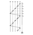
- FIG. 3 is a diagram for explaining an example of ultrasonic transmission timing at the time of acquisition of flow RF data performed by the ultrasonic observation apparatus according to the embodiment of the present invention.
- echo signals are acquired sequentially by alternate scanning. In the sequential alternating scan, for each of a plurality of partial regions (partial regions R 11 to R 15 , hereinafter also referred to as blocks) obtained by dividing the region of interest R 1 set for the scanning region 100 shown in FIG. 2 into a plurality of regions.
- a plurality of scans are performed for a plurality of scan lines set in each partial region. For example, when five scan lines (for example, the first scan line, the second scan line,..., The fifth scan line) are set in a certain partial area, scanning is performed from the first scan line to the fifth scan line in order. After that, returning to the first scan line again, a plurality of echo signals are acquired for each scan line. Specifically, as shown in FIG.
- time scanning for the first time of the first scan line in t 21 (1) is performed, scanning continued for 1 at time t 22 and time of the second scanning lines (2) is performed, and is performed scanning at time t 23 the first of the third scan lines (3), is performed scanning at time t 24 the first of the fourth scan line (4), first at time t 25
- the fifth scan line (5) which is the last scan line, is scanned.
- the second scan of the first scan line is performed, and the second scan is sequentially performed.
- the sequential alternating scan a plurality of echo signals are acquired in each scan line by performing a set number of scan scans. Note that at the scan timing in the sequential alternating scan, at least the scan interval in the same scan line is constant.
- ROI R 1 is for example a region which forms a trapezoidal or fan is set.
- a line segment parallel to the depth direction (sound ray direction) of the ultrasonic transducer 21 is connected to the end portions of the line segment, and the depth from the surface of the ultrasonic transducer 21 is the same.
- a fan-shaped area surrounded by a connecting curve may be used as a region of interest.
- the “curve” here corresponds to the scanning direction of the ultrasonic transducer 21.
- the signal processing unit 32 generates digital B-mode reception data and flow reception data based on the flow RF data received from the transmission / reception unit 31.
- the signal processing unit 32 includes a B-mode signal processing unit 321 that generates B-mode reception data, and a flow signal processing unit 322 that generates flow reception data.
- the B-mode signal processing unit 321 performs known processing such as band-pass filter, envelope detection, and logarithmic conversion on the RF data to generate digital B-mode reception data.
- logarithmic conversion a common logarithm of an amount obtained by dividing RF data by a reference voltage is taken and expressed as a decibel value.
- the B-mode reception data includes a plurality of line data in which the amplitude or intensity of the reception signal indicating the intensity of reflection of the ultrasonic pulse is arranged along the transmission / reception direction (depth direction) of the ultrasonic pulse.
- the signal processing unit 32 outputs the generated B-mode reception data for one frame to the image processing unit 33.
- the flow signal processing unit 322 performs the above-described processing to generate flow reception data including a plurality of line data based on the flow RF data.
- the flow signal processing unit 322 uses the RF data in the same direction to calculate a change in amplitude or intensity of the reception signal indicating the intensity of reflection of the ultrasonic pulse for each predetermined depth, and the calculated change amount A sound ray (line data) is generated.
- the flow reception data is composed of a plurality of line data in which the amplitude or intensity change amount of the reception signal indicating the intensity of reflection of the ultrasonic pulse is arranged along the transmission / reception direction (depth direction) of the ultrasonic pulse.
- the flow signal processing unit 322 detects the received flow RF data, and then outputs the detected RF data to the frame memory 34.
- the signal processing unit 32 is realized using a CPU (Central Processing Unit), various arithmetic circuits, and the like.
- the image processing unit 33 generates B-mode image data and flow image data based on the B-mode reception data and the flow reception data received from the signal processing unit 32, respectively.
- the image processing unit 33 includes a B mode image generation unit 331 that generates B mode image data based on the B mode reception data, a flow image generation unit 332 that generates flow image data based on the flow reception data, and a flow An image composition unit 333 performs image composition by superimposing image data on B-mode image data.
- the B-mode image generation unit 331 performs signal processing using known techniques such as scan converter processing, gain processing, and contrast processing on the B-mode reception data output from the signal processing unit 32, and a display device
- the B-mode image data is generated by thinning out the data according to the data step width determined according to the image display range in 4.
- the scan direction of the B-mode reception data is converted from the ultrasonic scan direction to the display direction of the display device 4.
- the B-mode image is a grayscale image in which values of R (red), G (green), and B (blue), which are variables when the RGB color system is adopted as a color space, are matched.
- the flow image generation unit 332 generates flow image data based on the flow reception data received from the signal processing unit 32. Specifically, the flow image generation unit 332 adds color information to each depth position according to the relative change amount in the set region of interest, and interpolates the color information at the missing position. As a result, flow image data is generated.
- the color information is Doppler information indicating the presence / absence of blood flow and the direction of blood flow at each position, and is information expressed in a color that is relatively determined by the ratio of the amount of change in the region where the Doppler information is generated, for example, the region of interest. is there.
- the B-mode image generation unit 331 and the flow image generation unit 332 perform coordinate transformation that rearranges the B-mode reception data and the flow reception data from the signal processing unit 32 so that the scanning range can be spatially represented correctly, By interpolating between the B-mode reception data and between the flow reception data, the gaps between the reception data are filled, and B-mode image data and flow image data are generated.
- the image composition unit 333 generates image data for display by superimposing the flow image data on the generated B-mode image data according to the coordinate information.
- the frame memory 34 is realized by using, for example, a ring buffer, and stores RF data for one line of flow detected by the signal processing unit 32 in time series.
- the frame memory 34 may store RF data for a plurality of lines of flow along a time series. In this case, when the capacity is insufficient (when the flow reception data of a predetermined number of lines is stored), the frame memory 34 overwrites the oldest flow RF data with the latest flow RF data to obtain the latest flow data.
- the RF data for flow is stored in a predetermined number of lines in chronological order.
- the frame memory 34 may store B-mode reception data, B-mode image data, and flow image data.
- the computing unit 35 detects the presence or absence of a reverberation echo that occurs when scanning each partial region, and sets a repetition frequency (PRF) related to transmission of ultrasonic waves according to the presence or absence of the reverberation echo.
- PRF repetition frequency
- the setting of PFR corresponds to the setting of the number of scan lines.
- the calculation unit 35 includes a subtraction unit 351, a determination unit 352, and a PRF setting unit 353.
- the subtraction unit 351 refers to the frame memory 34 in the partial area, and scans the RF data of the scan line obtained by first scanning in the partial area, and the RF data of the same scan line scanned after the second time. Subtraction is performed to calculate difference data.
- Subtraction unit 351 for example, difference data between the RF data of the first scan data by scanning the RF data and the second time of the first scan line which is scanned first in the partial region R 11, specifically, the second time Difference data having a difference obtained by subtracting the first first scan line RF data from the first scan line RF data at a predetermined time interval (depth interval) is calculated.
- the subtractor 351 preferably calculates difference data using RF data after noise canceller using a Doppler filter.
- the determination unit 352 compares the difference calculated by the subtraction unit 351 with the threshold value stored in the storage unit 38, and is transmitted during the scan line scan before the scan line in the second and subsequent scan data. It is determined whether or not a reverberation echo by ultrasonic waves is included. Specifically, when the RF data of the first scan line is acquired for the second time, an echo signal by an ultrasonic wave transmitted at the time of acquiring the RF data of the first scan line may be received. It becomes. This reverberation echo is not originally included as the RF data of the second first scan line, and appears as noise when generating a flow image.
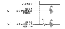
- FIG. 4 is a diagram for explaining received echoes when acquiring flow RF data performed by the ultrasonic observation apparatus according to the embodiment of the present invention.
- the received echo of the scan line acquired by the ultrasonic wave transmitted for the first time for example, the received echo shown in FIG. 4A
- the ultrasonic transducer 21 does not scan different scan lines, the ultrasonic transducer 21 does not receive the reverberation echo but receives the echo E 1 corresponding to the blood flow.
- the received echo scanline acquired by the ultrasonic wave transmitted secondly or later for example, the second received echo shown in FIG.
- the difference data calculated by the subtracting unit 351 becomes a waveform having a peak corresponding to the reverberation echo.
- the determination unit 352 determines the presence or absence of a reverberation echo by comparing the above-described difference data with a threshold and detecting this peak.
- the threshold value used here is a value determined based on a peak value that can be detected as a reverberant echo.
- reverberation echoes occur between adjacent scan lines, they are spatially close and are therefore continuously represented in the flow image.
- spatially separated such as the first scan line and the fifth scan line, it is expressed discontinuously as a flow image. It is assumed that a reverberant echo detected when the user is far away is detected.
- the PRF setting unit 353 sets the PRF according to the determination result of the determination unit 352. Specifically, the PRF setting unit 353 changes the PRF setting when the determination unit 352 determines that a reverberation echo is included. The PRF setting unit 353 outputs the set PRF to the control unit 37.
- the input unit 36 is realized by using a user interface such as a keyboard, a mouse, a trackball, and a touch panel, and accepts input of various information.
- the input unit 36 outputs the received information to the control unit 37.
- the control unit 37 controls the entire ultrasound diagnostic system 1.
- the control unit 37 is realized using a CPU having arithmetic and control functions, various arithmetic circuits, and the like.
- the control unit 37 reads out information stored and stored in the storage unit 38 from the storage unit 38 and executes various arithmetic processes related to the operation method of the ultrasonic observation device 3 to control the ultrasonic observation device 3 in an integrated manner. To do.
- the control unit 37 may be configured using a CPU or the like common to the signal processing unit 32.
- the control unit 37 Based on the PRF set by the PRF setting unit 353, the control unit 37 sets the number of scan lines in the partial region, the setting of the transmission timing of ultrasonic waves, and the like in the sequential alternating scan performed when acquiring the flow image.
- a sequential alternate scan control unit 371 that generates a transmission signal (pulse signal) including information and performs sequential alternate scan control is provided.
- the storage unit 38 stores various programs for operating the ultrasound diagnostic system 1, data including various parameters necessary for the operation of the ultrasound diagnostic system 1, and the like.
- the storage unit 38 includes a sequential alternate scan information storage unit 381 that stores sequential alternate scan information, which is information related to sequential alternate scan settings.
- the determination unit 352 described above stores a threshold value (peak information) for determining the presence / absence of a reverberation echo, and information on the PRF set by the PRF setting unit 353.
- the storage unit 38 stores various programs including an operation program for executing the operation method of the ultrasonic diagnostic system 1.
- the operation program can be recorded on a computer-readable recording medium such as a hard disk, a flash memory, a CD-ROM, a DVD-ROM, or a flexible disk and widely distributed.
- the various programs described above can also be obtained by downloading via a communication network.
- the communication network here is realized by, for example, an existing public line network, LAN (Local Area Network), WAN (Wide Area Network), etc., and may be wired or wireless.
- the storage unit 38 having the above configuration is realized using a ROM (Read Only Memory) in which various programs are installed in advance, and a RAM (Random Access Memory) that stores calculation parameters and data of each process. .
- ROM Read Only Memory
- RAM Random Access Memory
- FIG. 5 is a diagram for explaining ultrasonic transmission processing under the control of the ultrasonic observation apparatus according to the embodiment of the present invention. In the present embodiment, it is assumed that line scanning is performed when the pulse falls or rises in B-mode scanning.
- flow mode scanning is performed between B-mode scanning frames to obtain flow echo signals.
- description will be made assuming that line scanning for the flow mode is performed five times for each partial region.
- a plurality of signals obtained by this continuous line scanning and forming a set is called a packet, and a packet is formed for each partial area described above.
- Ultrasonic transmission processing in the one partial region between the time t 11 the time t 12 is performed. For example, during the period from time t 11 to time t 12 , ultrasonic transmission processing is performed on the region corresponding to partial region R 11 among partial regions R 11 to R 15 .
- each partial area for example, after scanning the scan line from the first scan line to the second scan line,...
- the scanning line scanning (packet acquisition) from the second scanning line to the fifth scanning line is repeated a predetermined number of times. Thereafter, ultrasonic transmission processing is sequentially performed in other partial areas.
- the reception echo for the flow mode for one frame can be acquired.
- the calculation unit 35 performs a process for determining whether or not there is a reverberation echo, and determines that there is a reverberation echo.
- the setting process (calculation step) is performed.
- FIG. 6 is a flowchart for explaining the PRF setting process performed by the ultrasonic observation apparatus according to the embodiment of the present invention. Hereinafter, description will be made assuming that each unit operates under the control of the control unit 37.
- the calculation unit 35 determines whether or not RF data (hereinafter also referred to as scan data) for the second scan line has been acquired in the partial region to be scanned.
- step S101: No When it is determined that the scan data of the second scan line has not been acquired (step S101: No), the calculation unit 35 repeats the confirmation of the scan data. On the other hand, when the calculation unit 35 determines that the scan data of the second scan line has been acquired (step S101: Yes), the calculation unit 35 proceeds to step S102.
- step S102 the subtraction unit 351 performs a subtraction process between the RF data of the first scan line scanned first (first) in the partial region and the RF data of the first scan line scanned second time to obtain difference data. Is calculated.
- the determination unit 352 compares the difference calculated by the subtraction unit 351 with the threshold value stored in the storage unit 38 to determine whether or not reverberation echo is included in the second scan data. Judgment is made (step S103). If the determination unit 352 determines that the difference is equal to or less than the threshold and the reverberation echo is not included in the second scan data (step S103: Yes), the process proceeds to step S104. On the other hand, when the determination unit 352 determines that the difference is larger than the threshold and the reverberation echo is included in the second scan data (step S103: No), the process proceeds to step S105.
- the PRF setting unit 353 After the determination by the determination unit 352, the PRF setting unit 353 performs the PRF setting in the next and subsequent sequential scans according to the determination result.
- the sequential alternate scan control unit 371 performs sequential alternate scan to which the set PRF is applied (sequential alternate scan control step).
- step S104 since the reverberation echo is not included in the second scan data, the PRF setting unit 353 maintains the PRF as it is. As a result, it is possible to receive the flow echo signal without the influence of the reverberation echo while maintaining the frame rate.
- step S105 since the reverberation echo is included in the second scan data, the PRF setting unit 353 sets the PRF so that this reverberation echo is not included.
- the PRF setting unit 353 changes the PRF so that the RF data of the first scan line after the third time does not include the reverberation echo while maintaining the reception interval of the echo signal of each scan line.
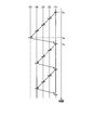
- FIG. 7 and 8 are diagrams for explaining the PRF setting change performed by the ultrasonic observation apparatus according to the embodiment of the present invention.
- the PRF setting unit 353 sets the interval between time t 31 and time t 32 that are reception intervals of echo signals on the same scan line,
- the PRF setting is changed by decreasing the number of scan lines and increasing the ultrasonic transmission interval between adjacent scan lines while maintaining the interval between t 32 and time t 33 .
- the reverberation echo E 10 generated from the ultrasonic wave transmitted at the time t 41 which is the ultrasonic transmission time of the line scan of the first final scan line is the echo E 2. are present in the ultrasonic transmission start time for a period of time of the second scan lines t 42 after for acquiring.
- the reverberation echo E 10 generated from first line scan of the last scan line ultrasonic waves transmitted to the time t 41 is an ultrasonic transmission time It comes before the time t 43 which is the ultrasonic transmission time of the second scan line.
- the PRF changing process by the PRF setting unit 353 can prevent the RF data (reception echo) of the first scan line after the first time from including the reverberation echo.
- a second time t 42 is an ultrasonic transmission start time of the line scanning of the first scan line as a reference point, the reverberation echo
- the time until E 10 disappears specifically, the PRF setting unit 353 counts the time t 45 from the time t 42 to the time t 44, and the ultrasonic transmission start time of the line scan of the last scan line.
- the shortest time (t 45 + t 46 ) per scan is calculated by adding the time t 45 to the time t 46 that is a count value from a certain time t 41 to the time t 42, and based on this shortest time
- the PRF that is the repetition frequency is calculated.
- Ultrasonic transmission interval after PRF change has only to become the shortest hours or more, for example, it has a distance from the (b) at time t 41 in FIG. 8 to time t 43.
- the PRF setting unit 353 sets the PRF according to the temporal position of the reverberation echo.
- the detection of the reverberant echo and the change of the PRF may be performed when sequentially scanning each partial region, that is, for each frame, or one or more set partial regions may be sequentially alternated. It may be performed when scanning is performed.
- the partial areas that are not subjected to reverberation echo detection and PRF change are set previously.
- the alternating scan is sequentially performed while maintaining the PRF.
- An appropriate PRF can be set for each partial region by detecting reverberant echo and changing the PRF each time when performing sequential alternating scanning of each partial region (for each frame).
- the amount of calculation can be reduced as compared with the case of performing each time.
- the flow signal processing unit 322 generates flow reception signal data including the amount of change in blood in the scanning region, using a plurality of reception signals for each scan line obtained by the line scanning for the flow mode.
- blood flow information is generated from a plurality of received signals based on the amount of change in amplitude or intensity for each depth.
- the blood flow information in this range may be acquired by receiving the amplitude and intensity at the entire depth of each line and using the set region of interest (ROI) as the scanning region.
- ROI region of interest
- blood flow information may be acquired using the entire image as a scanning region.
- the flow image generation unit 332 generates flow image data based on the flow reception data received from the signal processing unit 32.
- the image composition unit 333 superimposes the blood flow information on the B-mode image data by superimposing the flow image data generated by the flow image generation unit 332 on the B-mode image data generated by the B-mode image generation unit 331. Generated composite image data is generated.
- the scan data of the first scan line and the scan data of the second and subsequent scan lines the scan data of the same scan line as the first scan line
- the PRF that is the repetition frequency is changed. Therefore, the reverberation echo between spatially separated scan data when the flow image is generated
- the influence by can be suppressed. That is, according to the present embodiment, it is possible to suppress the influence of noise in the flow image due to reverberation echoes at the time of sequential alternating scanning.
- the reverberation echo is generated using the scan data of the second scan line that is repeatedly performed after scanning all the scan lines of the first scan line, the second scan line,..., The fifth scan line.
- reverberation echoes are detected by performing scanning for detection before sequentially performing alternate scanning.
- FIG. 9 is a diagram for explaining processing in the flow mode performed by the ultrasonic observation apparatus according to the first modification of the embodiment of the present invention, and sequentially when the determination unit 352 determines that no reverberation echo is included. It is a figure explaining alternate scanning.
- the sequential alternate scan control unit 371 first acquires the scan data of the first scan line of the partial region at time t 51 , then acquires the scan data of the last scan line at time t 52 , It gets the subsequent scan data for the first scan line of the second at time t 53, as described above, first the subtraction unit 351, scanned in the RF data and the second time of the first scan line scanned in the first Difference data between the scan data and the RF data is calculated. Thereafter, the determination unit 352 detects the reverberation echo using the difference data.
- FIG. 10 is a diagram for explaining the processing in the flow mode performed by the ultrasonic observation apparatus according to the first modification of the embodiment of the present invention, in which the determination unit 352 sequentially alternates when it is determined to include a reverberation echo. It is a figure explaining a scan. As shown in FIG. 10, when a reverberation echo exists, the PRF is changed and the scan line is reduced as described above. For this reason, scan data of the first to fourth scan lines are acquired in the sequential alternating scan. In this case, the time interval between the nth scan data acquisition timing and the (n + 1) th scan data acquisition timing is the nth scan data acquisition timing and the (n + 1) th scan data acquisition timing before the PRF change. Is equivalent to the time interval of
- the time required for the flow mode scanning particularly when the reverberation echo is detected is described above.
- the time required for the flow mode scanning according to the embodiment can be shortened.
- FIG. 11 is a diagram for explaining the processing in the flow mode performed by the ultrasonic observation apparatus according to the second modification of the embodiment of the present invention, in which the determination unit 352 sequentially alternates when it is determined to include a reverberation echo. It is a figure explaining a scan.
- the PRF is changed and the scan line is reduced as described above.
- the second modification it resets the sequential alternating scan at time t 63, to start the sequential alternating scan to acquire new scan data of the first to fourth scan line from the time t 63.
- an ultrasonic observation apparatus it may be configured by connecting circuits having each function by a bus, or may be configured such that some functions are built in a circuit structure of other functions. .
- the ultrasonic endoscope 2 having an optical system such as a light guide has been described as an ultrasonic probe.
- the imaging optical system and the imaging element are not limited to the ultrasonic endoscope 2.
- the ultrasonic probe which does not have may be used.
- a thin ultrasonic miniature probe without an optical system may be applied as the ultrasonic probe.
- Ultrasonic miniature probes are usually inserted into the biliary tract, bile duct, pancreatic duct, trachea, bronchi, urethra, ureter, and used to observe surrounding organs (pancreas, lung, prostate, bladder, lymph nodes, etc.).
- an external ultrasonic probe that irradiates ultrasonic waves from the body surface of the subject may be applied.
- the extracorporeal ultrasonic probe is usually used in direct contact with the body surface when observing an abdominal organ (liver, gallbladder, bladder), breast (particularly mammary gland), and thyroid gland.
- the ultrasonic vibrator may be a linear vibrator, a radial vibrator, or a convex vibrator.
- the scanning area is rectangular (rectangular, square), and when the ultrasonic transducer is a radial or convex transducer, the scanning area is fan-shaped or annular.
- the ultrasonic endoscope may be one that mechanically scans the ultrasonic transducer, or a plurality of elements are arranged in an array as the ultrasonic transducer, and the elements involved in transmission and reception are switched electronically. Alternatively, electronic scanning may be performed by delaying transmission / reception of each element.
- the ultrasonic observation apparatus, the operation method of the ultrasonic observation apparatus, and the operation program of the ultrasonic observation apparatus according to the present invention are useful for suppressing the influence of noise caused by reverberant echoes during sequential scans. is there.
Landscapes
- Engineering & Computer Science (AREA)
- Health & Medical Sciences (AREA)
- Physics & Mathematics (AREA)
- Life Sciences & Earth Sciences (AREA)
- Radar, Positioning & Navigation (AREA)
- Remote Sensing (AREA)
- Computer Networks & Wireless Communication (AREA)
- General Physics & Mathematics (AREA)
- Acoustics & Sound (AREA)
- Nuclear Medicine, Radiotherapy & Molecular Imaging (AREA)
- Molecular Biology (AREA)
- Biophysics (AREA)
- Veterinary Medicine (AREA)
- Pathology (AREA)
- Radiology & Medical Imaging (AREA)
- Biomedical Technology (AREA)
- Heart & Thoracic Surgery (AREA)
- Medical Informatics (AREA)
- Public Health (AREA)
- Surgery (AREA)
- Animal Behavior & Ethology (AREA)
- General Health & Medical Sciences (AREA)
- Computer Vision & Pattern Recognition (AREA)
- Hematology (AREA)
- Physiology (AREA)
- Ultra Sonic Daignosis Equipment (AREA)
Abstract
Description
図1は、本発明の一実施の形態に係る超音波観測装置を備えた超音波診断システムの構成を示すブロック図である。同図に示す超音波診断システム1は、観測対象である被検体へ超音波を送信し、該被検体で反射された超音波を受信する超音波内視鏡2と、超音波内視鏡2が取得した超音波信号に基づいて超音波画像を生成する超音波観測装置3と、超音波観測装置3が生成した超音波画像を表示する表示装置4と、を備える。
上述した実施の形態では、第1スキャンライン、第2スキャンライン、・・・第5スキャンラインのすべてのスキャンラインを走査後に、繰り返し行われる2回目のスキャンラインのスキャンデータを用いて残響エコーを検出するものとして説明したが、本変形例1では、順次交互スキャンを行う前に、検出用の走査を行うことによって、残響エコーの検出を行う。図9は、本発明の実施の形態の変形例1に係る超音波観測装置が行うフローモード時の処理を説明する図であって、判断部352が残響エコーを含まないと判断した場合の順次交互スキャンを説明する図である。
上述した実施の形態では、順次交互スキャンを開始後に、残響エコーを検出し、検出結果によってPRFを変更するものとして説明したが、本変形例2では、PRFが変更された場合にリセットを行って、PRF変更後、変更されたPRFを用いて新たに順次交互スキャンを行う。図11は、本発明の実施の形態の変形例2に係る超音波観測装置が行うフローモード時の処理を説明する図であって、判断部352が残響エコーを含むと判断した場合の順次交互スキャンを説明する図である。
2 超音波内視鏡
3 超音波観測装置
4 表示装置
21 超音波振動子
31 送受信部
32 信号処理部
33 画像処理部
34 フレームメモリ
35 演算部
36 入力部
37 制御部
38 記憶部
321 Bモード用信号処理部
322 フロー用信号処理部
331 Bモード画像生成部
332 フロー画像生成部
333 画像合成部
351 減算部
352 判断部
353 PRF設定部
371 順次交互スキャン制御部
381 順次交互スキャン情報記憶部
Claims (11)
- 複数の深度方向に対して順次超音波を送信するとともに、この順で超音波の送信を繰り返す順次交互スキャンによって取得される複数のスキャンデータに基づいてドプラ情報を生成する超音波観測装置であって、
前記順次交互スキャンにおいて最初にスキャンする深度方向に前記超音波を送信することにより取得される第1スキャンデータと、前記最初にスキャンする深度方向と同一の深度方向に対して前記超音波を送信することにより取得される第2スキャンデータであって、2回目の前記超音波の送信により取得された第2スキャンデータとを比較演算する演算部と、
前記演算部の演算結果に基づいて、前記順次交互スキャンにおける前記超音波の送信を繰り返す繰り返し周波数を制御する順次交互スキャン制御部と、
を備えたことを特徴とする超音波観測装置。 - 前記演算部は、
前記第1スキャンデータと、前記第2スキャンデータとを減算する減算部と、
前記減算部の減算結果と、閾値とを比較して、前記第2スキャンデータにおける残響エコーの有無を判断する判断部と、
前記判断部により前記第2スキャンデータに前記残響エコーが存在すると判断された場合に、前記繰り返し周波数の設定変更を行う繰り返し周波数設定部と、
をさらに備えたことを特徴とする請求項1に記載の超音波観測装置。 - 前記繰り返し周波数設定部は、検出された前記残響エコーに基づき前記繰り返し周波数を設定するための加算時間を算出する
ことを特徴とする請求項2に記載の超音波観測装置。 - 前記繰り返し周波数設定部は、超音波送信の時間間隔が、設定されている超音波送信の時間間隔に前記加算時間を加算した時間以上となる時間を前記超音波送信の時間間隔とする前記繰り返し周波数を設定する
ことを特徴とする請求項3に記載の超音波観測装置。 - 前記判断部は、前記減算結果と閾値とを比較することによって残響エコーのピークを検出する
ことを特徴とする請求項2に記載の超音波観測装置。 - 前記ドプラ情報を生成する走査領域が複数の部分領域に分割されており、
前記順次交互スキャン制御部は、前記部分領域ごとに前記順次交互スキャンを実行させる制御を行い、
前記演算部は、設定された一つまたは複数の部分領域において、前記比較演算を行う
ことを特徴とする請求項1に記載の超音波観測装置。 - 前記繰り返し周波数設定部は、前記順次交互スキャンを行うスキャンライン数を変更することにより前記繰り返し周波数を設定する
ことを特徴とする請求項2に記載の超音波観測装置。 - 前記順次交互スキャン制御部は、前記順次交互スキャンの前記繰り返し周波数をフレームごとに設定する制御を行う
ことを特徴とする請求項1に記載の超音波観測装置。 - 前記順次交互スキャン制御部は、前記順次交互スキャンを行う前に、前記順次交互スキャンにおいて最初にスキャンする深度方向に前記超音波を送信し、前記順次交互スキャンにおいて最後にスキャンする深度方向に前記超音波を送信した後、前記最初にスキャンする深度方向と同一の深度方向に対して前記超音波を送信する事前処理を行わせ、
前記演算部は、前記事前処理により取得された前記第1スキャンデータと前記第2スキャンデータとを比較演算し、
前記順次交互スキャン制御部は、前記事前処理に基づくスキャンデータによる前記演算部の演算結果に基づいて、前記順次交互スキャンにおける前記繰り返し周波数を制御する
ことを特徴とする請求項1に記載の超音波観測装置。 - 複数の深度方向に対して順次超音波を送信するとともに、この順で超音波の送信を繰り返す順次交互スキャンによって取得される複数のスキャンデータに基づいてドプラ情報を生成する超音波観測装置の作動方法であって、
演算部が、前記順次交互スキャンにおいて最初にスキャンする深度方向に前記超音波を送信することにより取得される第1スキャンデータと、前記最初にスキャンする深度方向と同一の深度方向に対して前記超音波を送信することにより取得される第2スキャンデータであって、2回目の前記超音波の送信により取得された第2スキャンデータとを比較演算する演算ステップと、
順次交互スキャン制御部が、前記演算部の演算結果に基づいて、前記順次交互スキャンにおける前記超音波の送信を繰り返す繰り返し周波数を制御する順次交互スキャン制御ステップと、
を含むことを特徴とする超音波観測装置の作動方法。 - 複数の深度方向に対して順次超音波を送信するとともに、この順で超音波の送信を繰り返す順次交互スキャンによって取得される複数のスキャンデータに基づいてドプラ情報を生成する超音波観測装置に、
前記順次交互スキャンにおいて最初にスキャンする深度方向に前記超音波を送信することにより取得される第1スキャンデータと、前記最初にスキャンする深度方向と同一の深度方向に対して前記超音波を送信することにより取得される第2スキャンデータであって、2回目の前記超音波の送信により取得された第2スキャンデータとを比較演算する演算手順と、
前記演算手順の演算結果に基づいて、前記順次交互スキャンにおける前記超音波の送信を繰り返す繰り返し周波数を制御する順次交互スキャン制御手順と、
を実行させることを特徴とする超音波観測装置の作動プログラム。
Priority Applications (4)
| Application Number | Priority Date | Filing Date | Title |
|---|---|---|---|
| JP2017562928A JP6513230B2 (ja) | 2016-01-22 | 2017-01-20 | 超音波観測装置、超音波観測装置の作動方法、および超音波観測装置の作動プログラム |
| CN201780007589.XA CN108472013A (zh) | 2016-01-22 | 2017-01-20 | 超声波观测装置、超声波观测装置的工作方法以及超声波观测装置的工作程序 |
| EP17741552.8A EP3406198A4 (en) | 2016-01-22 | 2017-01-20 | ULTRASONIC OBSERVATION DEVICE, METHOD OF OPERATING THE ULTRASONIC OBSERVATION DEVICE AND A PROGRAM FOR OPERATING THE ULTRASONIC OBSERVATION DEVICE |
| US16/040,737 US20180333139A1 (en) | 2016-01-22 | 2018-07-20 | Ultrasound observation device, method of operating ultrasound observation device, and program computer-readable recording medium |
Applications Claiming Priority (2)
| Application Number | Priority Date | Filing Date | Title |
|---|---|---|---|
| JP2016010711 | 2016-01-22 | ||
| JP2016-010711 | 2016-01-22 |
Related Child Applications (1)
| Application Number | Title | Priority Date | Filing Date |
|---|---|---|---|
| US16/040,737 Continuation US20180333139A1 (en) | 2016-01-22 | 2018-07-20 | Ultrasound observation device, method of operating ultrasound observation device, and program computer-readable recording medium |
Publications (1)
| Publication Number | Publication Date |
|---|---|
| WO2017126675A1 true WO2017126675A1 (ja) | 2017-07-27 |
Family
ID=59361841
Family Applications (1)
| Application Number | Title | Priority Date | Filing Date |
|---|---|---|---|
| PCT/JP2017/001971 Ceased WO2017126675A1 (ja) | 2016-01-22 | 2017-01-20 | 超音波観測装置、超音波観測装置の作動方法、および超音波観測装置の作動プログラム |
Country Status (5)
| Country | Link |
|---|---|
| US (1) | US20180333139A1 (ja) |
| EP (1) | EP3406198A4 (ja) |
| JP (1) | JP6513230B2 (ja) |
| CN (1) | CN108472013A (ja) |
| WO (1) | WO2017126675A1 (ja) |
Cited By (1)
| Publication number | Priority date | Publication date | Assignee | Title |
|---|---|---|---|---|
| JP2022155177A (ja) * | 2021-03-30 | 2022-10-13 | 富士フイルムヘルスケア株式会社 | 超音波ct装置、その制御方法、および、超音波ct装置の制御プログラム |
Families Citing this family (7)
| Publication number | Priority date | Publication date | Assignee | Title |
|---|---|---|---|---|
| US11986356B2 (en) * | 2019-11-21 | 2024-05-21 | Koninklijke Philips N.V. | Reduction of reverberation artifacts in ultrasound images and associated devices, systems, and methods |
| CN114305502B (zh) * | 2020-09-29 | 2024-09-20 | 深圳迈瑞生物医疗电子股份有限公司 | 乳腺超声扫描方法、装置和存储介质 |
| CN118697375A (zh) * | 2020-11-18 | 2024-09-27 | 武汉联影医疗科技有限公司 | 超声成像方法、装置、系统和存储介质 |
| WO2022041616A1 (en) | 2020-11-18 | 2022-03-03 | Wuhan United Imaging Healthcare Co., Ltd. | System and method for ultrasound imaging |
| EP4230145B1 (en) | 2020-11-18 | 2025-12-17 | Wuhan United Imaging Healthcare Co., Ltd. | Ultrasonic imaging method, system and storage medium |
| CN120661184A (zh) * | 2021-09-09 | 2025-09-19 | 深圳迈瑞生物医疗电子股份有限公司 | 超声血流成像方法及超声成像装置 |
| CN114767164A (zh) * | 2022-04-25 | 2022-07-22 | 飞依诺科技股份有限公司 | 环阵超声内镜的扫查方法、设备及存储介质 |
Citations (4)
| Publication number | Priority date | Publication date | Assignee | Title |
|---|---|---|---|---|
| JP2003111759A (ja) * | 2001-08-24 | 2003-04-15 | Ge Medical Systems Global Technology Co Llc | 超音波撮像の空間分解能及び時間分解能を改善する方法及び装置 |
| JP2005058332A (ja) * | 2003-08-08 | 2005-03-10 | Hitachi Medical Corp | 超音波診断装置 |
| JP2006198075A (ja) | 2005-01-19 | 2006-08-03 | Aloka Co Ltd | 超音波診断装置 |
| JP2007244501A (ja) * | 2006-03-14 | 2007-09-27 | Toshiba Corp | 超音波診断装置およびその画像処理方法、その画像処理プログラム |
Family Cites Families (11)
| Publication number | Priority date | Publication date | Assignee | Title |
|---|---|---|---|---|
| JPS5854941A (ja) * | 1981-09-29 | 1983-04-01 | 株式会社島津製作所 | 超音波診断装置 |
| JP2969073B2 (ja) * | 1995-12-28 | 1999-11-02 | アロカ株式会社 | 超音波診断装置 |
| JP2001252273A (ja) * | 2000-03-09 | 2001-09-18 | Hitachi Medical Corp | 超音波診断装置 |
| WO2006009469A2 (en) * | 2004-07-23 | 2006-01-26 | Angelsen Bjoern A J | Ultrasound imaging using non-linear manipulation of forward propagation |
| JP4820210B2 (ja) * | 2006-05-11 | 2011-11-24 | ジーイー・メディカル・システムズ・グローバル・テクノロジー・カンパニー・エルエルシー | 超音波診断装置及び超音波診断画像生成方法 |
| JP4309936B2 (ja) * | 2007-01-05 | 2009-08-05 | オリンパスメディカルシステムズ株式会社 | 超音波診断装置 |
| US20080242994A1 (en) * | 2007-03-29 | 2008-10-02 | Aloka Co., Ltd. | Methods and apparatus for ultrasound imaging |
| JP5159480B2 (ja) * | 2008-07-11 | 2013-03-06 | 株式会社東芝 | 超音波診断装置および超音波診断装置の制御プログラム |
| JP4465018B2 (ja) * | 2008-09-09 | 2010-05-19 | オリンパスメディカルシステムズ株式会社 | 超音波診断装置 |
| JP2012139489A (ja) * | 2010-12-16 | 2012-07-26 | Toshiba Corp | 超音波診断装置及びその制御方法 |
| US20150253428A1 (en) * | 2013-03-15 | 2015-09-10 | Leap Motion, Inc. | Determining positional information for an object in space |
-
2017
- 2017-01-20 WO PCT/JP2017/001971 patent/WO2017126675A1/ja not_active Ceased
- 2017-01-20 JP JP2017562928A patent/JP6513230B2/ja not_active Expired - Fee Related
- 2017-01-20 EP EP17741552.8A patent/EP3406198A4/en not_active Withdrawn
- 2017-01-20 CN CN201780007589.XA patent/CN108472013A/zh active Pending
-
2018
- 2018-07-20 US US16/040,737 patent/US20180333139A1/en not_active Abandoned
Patent Citations (4)
| Publication number | Priority date | Publication date | Assignee | Title |
|---|---|---|---|---|
| JP2003111759A (ja) * | 2001-08-24 | 2003-04-15 | Ge Medical Systems Global Technology Co Llc | 超音波撮像の空間分解能及び時間分解能を改善する方法及び装置 |
| JP2005058332A (ja) * | 2003-08-08 | 2005-03-10 | Hitachi Medical Corp | 超音波診断装置 |
| JP2006198075A (ja) | 2005-01-19 | 2006-08-03 | Aloka Co Ltd | 超音波診断装置 |
| JP2007244501A (ja) * | 2006-03-14 | 2007-09-27 | Toshiba Corp | 超音波診断装置およびその画像処理方法、その画像処理プログラム |
Non-Patent Citations (1)
| Title |
|---|
| See also references of EP3406198A4 |
Cited By (2)
| Publication number | Priority date | Publication date | Assignee | Title |
|---|---|---|---|---|
| JP2022155177A (ja) * | 2021-03-30 | 2022-10-13 | 富士フイルムヘルスケア株式会社 | 超音波ct装置、その制御方法、および、超音波ct装置の制御プログラム |
| JP7522692B2 (ja) | 2021-03-30 | 2024-07-25 | 富士フイルムヘルスケア株式会社 | 超音波ct装置、その制御方法、および、超音波ct装置の制御プログラム |
Also Published As
| Publication number | Publication date |
|---|---|
| US20180333139A1 (en) | 2018-11-22 |
| EP3406198A1 (en) | 2018-11-28 |
| CN108472013A (zh) | 2018-08-31 |
| EP3406198A4 (en) | 2019-10-09 |
| JP6513230B2 (ja) | 2019-05-15 |
| JPWO2017126675A1 (ja) | 2018-11-22 |
Similar Documents
| Publication | Publication Date | Title |
|---|---|---|
| JP6513230B2 (ja) | 超音波観測装置、超音波観測装置の作動方法、および超音波観測装置の作動プログラム | |
| JP5349115B2 (ja) | 超音波診断装置及びその制御プログラム | |
| CN104825187B (zh) | 超声波诊断装置、图像处理装置以及图像处理方法 | |
| JP2015054056A (ja) | 超音波診断装置及び超音波イメージングプログラム | |
| US11690600B2 (en) | Ultrasound observation apparatus, operation method of ultrasound observation apparatus, and computer-readable recording medium | |
| CN105939674A (zh) | 超声波诊断装置、超声波诊断装置的工作方法以及超声波诊断装置的工作程序 | |
| JP2017006213A (ja) | 超音波診断装置及び制御プログラム | |
| US20180210080A1 (en) | Ultrasound observation apparatus | |
| WO2016098429A1 (ja) | 超音波観測装置 | |
| WO2018142937A1 (ja) | 超音波観測装置、超音波観測装置の作動方法および超音波観測装置の作動プログラム | |
| WO2018163793A1 (ja) | 超音波観測装置、超音波観測装置の作動方法、及び超音波観測装置の作動プログラム | |
| WO2018163827A1 (ja) | 超音波観測装置、超音波観測装置の作動方法、及び超音波観測装置の作動プログラム | |
| JP5932183B1 (ja) | 超音波診断装置、超音波診断装置の作動方法および超音波診断装置の作動プログラム | |
| JP6726744B2 (ja) | 超音波観測装置、超音波観測装置の作動方法、及び超音波観測装置の作動プログラム | |
| JP6530660B2 (ja) | 超音波観測装置、超音波観測装置の作動方法および超音波観測装置の作動プログラム | |
| US20190008483A1 (en) | Ultrasound observation apparatus, method of operating ultrasound observation apparatus, and computer readable recording medium | |
| CN113556979B (zh) | 超声波观测装置、超声波观测装置的工作方法以及超声波观测装置的工作程序 | |
| WO2020157870A1 (ja) | 超音波観測装置、超音波観測装置の作動方法および超音波観測装置の作動プログラム | |
| JP2018192117A (ja) | 超音波観測装置、超音波観測装置の作動方法および超音波観測装置の作動プログラム | |
| JP7155394B2 (ja) | 超音波観測装置、超音波観測装置の作動方法および超音波観測装置の作動プログラム | |
| JP2017217359A (ja) | 超音波観測装置、超音波観測装置の作動方法、及び超音波観測装置の作動プログラム | |
| JP6022135B1 (ja) | 超音波診断装置、超音波診断装置の作動方法および超音波診断装置の作動プログラム | |
| JP6379059B2 (ja) | 超音波観測装置、超音波観測装置の作動方法、超音波観測装置の作動プログラムおよび超音波診断システム | |
| US20260060657A1 (en) | Ultrasound diagnosis apparatus, ultrasound diagnosis method, and non-transitory computer readable storage medium | |
| JP2017035300A (ja) | 超音波観測装置、超音波観測装置の作動方法、超音波観測装置の作動プログラム及び超音波観測システム |
Legal Events
| Date | Code | Title | Description |
|---|---|---|---|
| 121 | Ep: the epo has been informed by wipo that ep was designated in this application |
Ref document number: 17741552 Country of ref document: EP Kind code of ref document: A1 |
|
| WWE | Wipo information: entry into national phase |
Ref document number: 2017562928 Country of ref document: JP |
|
| NENP | Non-entry into the national phase |
Ref country code: DE |
|
| WWE | Wipo information: entry into national phase |
Ref document number: 2017741552 Country of ref document: EP |
|
| ENP | Entry into the national phase |
Ref document number: 2017741552 Country of ref document: EP Effective date: 20180822 |