WO2017126698A1 - 非水系リチウム型蓄電素子 - Google Patents
非水系リチウム型蓄電素子 Download PDFInfo
- Publication number
- WO2017126698A1 WO2017126698A1 PCT/JP2017/002033 JP2017002033W WO2017126698A1 WO 2017126698 A1 WO2017126698 A1 WO 2017126698A1 JP 2017002033 W JP2017002033 W JP 2017002033W WO 2017126698 A1 WO2017126698 A1 WO 2017126698A1
- Authority
- WO
- WIPO (PCT)
- Prior art keywords
- positive electrode
- active material
- storage element
- less
- electrode active
- Prior art date
- Legal status (The legal status is an assumption and is not a legal conclusion. Google has not performed a legal analysis and makes no representation as to the accuracy of the status listed.)
- Ceased
Links
Classifications
-
- H—ELECTRICITY
- H01—ELECTRIC ELEMENTS
- H01G—CAPACITORS; CAPACITORS, RECTIFIERS, DETECTORS, SWITCHING DEVICES, LIGHT-SENSITIVE OR TEMPERATURE-SENSITIVE DEVICES OF THE ELECTROLYTIC TYPE
- H01G11/00—Hybrid capacitors, i.e. capacitors having different positive and negative electrodes; Electric double-layer [EDL] capacitors; Processes for the manufacture thereof or of parts thereof
- H01G11/04—Hybrid capacitors
- H01G11/06—Hybrid capacitors with one of the electrodes allowing ions to be reversibly doped thereinto, e.g. lithium ion capacitors [LIC]
-
- H—ELECTRICITY
- H01—ELECTRIC ELEMENTS
- H01G—CAPACITORS; CAPACITORS, RECTIFIERS, DETECTORS, SWITCHING DEVICES, LIGHT-SENSITIVE OR TEMPERATURE-SENSITIVE DEVICES OF THE ELECTROLYTIC TYPE
- H01G11/00—Hybrid capacitors, i.e. capacitors having different positive and negative electrodes; Electric double-layer [EDL] capacitors; Processes for the manufacture thereof or of parts thereof
- H01G11/22—Electrodes
- H01G11/24—Electrodes characterised by structural features of the materials making up or comprised in the electrodes, e.g. form, surface area or porosity; characterised by the structural features of powders or particles used therefor
-
- H—ELECTRICITY
- H01—ELECTRIC ELEMENTS
- H01G—CAPACITORS; CAPACITORS, RECTIFIERS, DETECTORS, SWITCHING DEVICES, LIGHT-SENSITIVE OR TEMPERATURE-SENSITIVE DEVICES OF THE ELECTROLYTIC TYPE
- H01G11/00—Hybrid capacitors, i.e. capacitors having different positive and negative electrodes; Electric double-layer [EDL] capacitors; Processes for the manufacture thereof or of parts thereof
- H01G11/22—Electrodes
- H01G11/30—Electrodes characterised by their material
- H01G11/32—Carbon-based
- H01G11/34—Carbon-based characterised by carbonisation or activation of carbon
-
- H—ELECTRICITY
- H01—ELECTRIC ELEMENTS
- H01G—CAPACITORS; CAPACITORS, RECTIFIERS, DETECTORS, SWITCHING DEVICES, LIGHT-SENSITIVE OR TEMPERATURE-SENSITIVE DEVICES OF THE ELECTROLYTIC TYPE
- H01G11/00—Hybrid capacitors, i.e. capacitors having different positive and negative electrodes; Electric double-layer [EDL] capacitors; Processes for the manufacture thereof or of parts thereof
- H01G11/22—Electrodes
- H01G11/30—Electrodes characterised by their material
- H01G11/46—Metal oxides
-
- H—ELECTRICITY
- H01—ELECTRIC ELEMENTS
- H01G—CAPACITORS; CAPACITORS, RECTIFIERS, DETECTORS, SWITCHING DEVICES, LIGHT-SENSITIVE OR TEMPERATURE-SENSITIVE DEVICES OF THE ELECTROLYTIC TYPE
- H01G11/00—Hybrid capacitors, i.e. capacitors having different positive and negative electrodes; Electric double-layer [EDL] capacitors; Processes for the manufacture thereof or of parts thereof
- H01G11/22—Electrodes
- H01G11/30—Electrodes characterised by their material
- H01G11/50—Electrodes characterised by their material specially adapted for lithium-ion capacitors, e.g. for lithium-doping or for intercalation
-
- H—ELECTRICITY
- H01—ELECTRIC ELEMENTS
- H01M—PROCESSES OR MEANS, e.g. BATTERIES, FOR THE DIRECT CONVERSION OF CHEMICAL ENERGY INTO ELECTRICAL ENERGY
- H01M10/00—Secondary cells; Manufacture thereof
- H01M10/05—Accumulators with non-aqueous electrolyte
- H01M10/052—Li-accumulators
-
- H—ELECTRICITY
- H01—ELECTRIC ELEMENTS
- H01M—PROCESSES OR MEANS, e.g. BATTERIES, FOR THE DIRECT CONVERSION OF CHEMICAL ENERGY INTO ELECTRICAL ENERGY
- H01M10/00—Secondary cells; Manufacture thereof
- H01M10/05—Accumulators with non-aqueous electrolyte
- H01M10/052—Li-accumulators
- H01M10/0525—Rocking-chair batteries, i.e. batteries with lithium insertion or intercalation in both electrodes; Lithium-ion batteries
-
- H—ELECTRICITY
- H01—ELECTRIC ELEMENTS
- H01M—PROCESSES OR MEANS, e.g. BATTERIES, FOR THE DIRECT CONVERSION OF CHEMICAL ENERGY INTO ELECTRICAL ENERGY
- H01M10/00—Secondary cells; Manufacture thereof
- H01M10/05—Accumulators with non-aqueous electrolyte
- H01M10/056—Accumulators with non-aqueous electrolyte characterised by the materials used as electrolytes, e.g. mixed inorganic/organic electrolytes
- H01M10/0564—Accumulators with non-aqueous electrolyte characterised by the materials used as electrolytes, e.g. mixed inorganic/organic electrolytes the electrolyte being constituted of organic materials only
- H01M10/0566—Liquid materials
- H01M10/0567—Liquid materials characterised by the additives
-
- H—ELECTRICITY
- H01—ELECTRIC ELEMENTS
- H01M—PROCESSES OR MEANS, e.g. BATTERIES, FOR THE DIRECT CONVERSION OF CHEMICAL ENERGY INTO ELECTRICAL ENERGY
- H01M10/00—Secondary cells; Manufacture thereof
- H01M10/05—Accumulators with non-aqueous electrolyte
- H01M10/058—Construction or manufacture
- H01M10/0585—Construction or manufacture of accumulators having only flat construction elements, i.e. flat positive electrodes, flat negative electrodes and flat separators
-
- H—ELECTRICITY
- H01—ELECTRIC ELEMENTS
- H01M—PROCESSES OR MEANS, e.g. BATTERIES, FOR THE DIRECT CONVERSION OF CHEMICAL ENERGY INTO ELECTRICAL ENERGY
- H01M10/00—Secondary cells; Manufacture thereof
- H01M10/42—Methods or arrangements for servicing or maintenance of secondary cells or secondary half-cells
- H01M10/4242—Regeneration of electrolyte or reactants
-
- H—ELECTRICITY
- H01—ELECTRIC ELEMENTS
- H01M—PROCESSES OR MEANS, e.g. BATTERIES, FOR THE DIRECT CONVERSION OF CHEMICAL ENERGY INTO ELECTRICAL ENERGY
- H01M4/00—Electrodes
- H01M4/02—Electrodes composed of, or comprising, active material
- H01M4/13—Electrodes for accumulators with non-aqueous electrolyte, e.g. for lithium-accumulators; Processes of manufacture thereof
- H01M4/133—Electrodes based on carbonaceous material, e.g. graphite-intercalation compounds or CFx
-
- H—ELECTRICITY
- H01—ELECTRIC ELEMENTS
- H01M—PROCESSES OR MEANS, e.g. BATTERIES, FOR THE DIRECT CONVERSION OF CHEMICAL ENERGY INTO ELECTRICAL ENERGY
- H01M4/00—Electrodes
- H01M4/02—Electrodes composed of, or comprising, active material
- H01M4/13—Electrodes for accumulators with non-aqueous electrolyte, e.g. for lithium-accumulators; Processes of manufacture thereof
- H01M4/139—Processes of manufacture
- H01M4/1393—Processes of manufacture of electrodes based on carbonaceous material, e.g. graphite-intercalation compounds or CFx
-
- H—ELECTRICITY
- H01—ELECTRIC ELEMENTS
- H01M—PROCESSES OR MEANS, e.g. BATTERIES, FOR THE DIRECT CONVERSION OF CHEMICAL ENERGY INTO ELECTRICAL ENERGY
- H01M4/00—Electrodes
- H01M4/02—Electrodes composed of, or comprising, active material
- H01M4/62—Selection of inactive substances as ingredients for active masses, e.g. binders, fillers
-
- H—ELECTRICITY
- H01—ELECTRIC ELEMENTS
- H01G—CAPACITORS; CAPACITORS, RECTIFIERS, DETECTORS, SWITCHING DEVICES, LIGHT-SENSITIVE OR TEMPERATURE-SENSITIVE DEVICES OF THE ELECTROLYTIC TYPE
- H01G11/00—Hybrid capacitors, i.e. capacitors having different positive and negative electrodes; Electric double-layer [EDL] capacitors; Processes for the manufacture thereof or of parts thereof
- H01G11/54—Electrolytes
- H01G11/58—Liquid electrolytes
- H01G11/60—Liquid electrolytes characterised by the solvent
-
- H—ELECTRICITY
- H01—ELECTRIC ELEMENTS
- H01G—CAPACITORS; CAPACITORS, RECTIFIERS, DETECTORS, SWITCHING DEVICES, LIGHT-SENSITIVE OR TEMPERATURE-SENSITIVE DEVICES OF THE ELECTROLYTIC TYPE
- H01G11/00—Hybrid capacitors, i.e. capacitors having different positive and negative electrodes; Electric double-layer [EDL] capacitors; Processes for the manufacture thereof or of parts thereof
- H01G11/54—Electrolytes
- H01G11/58—Liquid electrolytes
- H01G11/62—Liquid electrolytes characterised by the solute, e.g. salts, anions or cations therein
-
- H—ELECTRICITY
- H01—ELECTRIC ELEMENTS
- H01M—PROCESSES OR MEANS, e.g. BATTERIES, FOR THE DIRECT CONVERSION OF CHEMICAL ENERGY INTO ELECTRICAL ENERGY
- H01M4/00—Electrodes
- H01M4/02—Electrodes composed of, or comprising, active material
- H01M2004/021—Physical characteristics, e.g. porosity, surface area
-
- H—ELECTRICITY
- H01—ELECTRIC ELEMENTS
- H01M—PROCESSES OR MEANS, e.g. BATTERIES, FOR THE DIRECT CONVERSION OF CHEMICAL ENERGY INTO ELECTRICAL ENERGY
- H01M2220/00—Batteries for particular applications
- H01M2220/10—Batteries in stationary systems, e.g. emergency power source in plant
-
- Y—GENERAL TAGGING OF NEW TECHNOLOGICAL DEVELOPMENTS; GENERAL TAGGING OF CROSS-SECTIONAL TECHNOLOGIES SPANNING OVER SEVERAL SECTIONS OF THE IPC; TECHNICAL SUBJECTS COVERED BY FORMER USPC CROSS-REFERENCE ART COLLECTIONS [XRACs] AND DIGESTS
- Y02—TECHNOLOGIES OR APPLICATIONS FOR MITIGATION OR ADAPTATION AGAINST CLIMATE CHANGE
- Y02E—REDUCTION OF GREENHOUSE GAS [GHG] EMISSIONS, RELATED TO ENERGY GENERATION, TRANSMISSION OR DISTRIBUTION
- Y02E60/00—Enabling technologies; Technologies with a potential or indirect contribution to GHG emissions mitigation
- Y02E60/10—Energy storage using batteries
-
- Y—GENERAL TAGGING OF NEW TECHNOLOGICAL DEVELOPMENTS; GENERAL TAGGING OF CROSS-SECTIONAL TECHNOLOGIES SPANNING OVER SEVERAL SECTIONS OF THE IPC; TECHNICAL SUBJECTS COVERED BY FORMER USPC CROSS-REFERENCE ART COLLECTIONS [XRACs] AND DIGESTS
- Y02—TECHNOLOGIES OR APPLICATIONS FOR MITIGATION OR ADAPTATION AGAINST CLIMATE CHANGE
- Y02E—REDUCTION OF GREENHOUSE GAS [GHG] EMISSIONS, RELATED TO ENERGY GENERATION, TRANSMISSION OR DISTRIBUTION
- Y02E60/00—Enabling technologies; Technologies with a potential or indirect contribution to GHG emissions mitigation
- Y02E60/13—Energy storage using capacitors
-
- Y—GENERAL TAGGING OF NEW TECHNOLOGICAL DEVELOPMENTS; GENERAL TAGGING OF CROSS-SECTIONAL TECHNOLOGIES SPANNING OVER SEVERAL SECTIONS OF THE IPC; TECHNICAL SUBJECTS COVERED BY FORMER USPC CROSS-REFERENCE ART COLLECTIONS [XRACs] AND DIGESTS
- Y02—TECHNOLOGIES OR APPLICATIONS FOR MITIGATION OR ADAPTATION AGAINST CLIMATE CHANGE
- Y02P—CLIMATE CHANGE MITIGATION TECHNOLOGIES IN THE PRODUCTION OR PROCESSING OF GOODS
- Y02P70/00—Climate change mitigation technologies in the production process for final industrial or consumer products
- Y02P70/50—Manufacturing or production processes characterised by the final manufactured product
-
- Y—GENERAL TAGGING OF NEW TECHNOLOGICAL DEVELOPMENTS; GENERAL TAGGING OF CROSS-SECTIONAL TECHNOLOGIES SPANNING OVER SEVERAL SECTIONS OF THE IPC; TECHNICAL SUBJECTS COVERED BY FORMER USPC CROSS-REFERENCE ART COLLECTIONS [XRACs] AND DIGESTS
- Y02—TECHNOLOGIES OR APPLICATIONS FOR MITIGATION OR ADAPTATION AGAINST CLIMATE CHANGE
- Y02T—CLIMATE CHANGE MITIGATION TECHNOLOGIES RELATED TO TRANSPORTATION
- Y02T10/00—Road transport of goods or passengers
- Y02T10/60—Other road transportation technologies with climate change mitigation effect
- Y02T10/70—Energy storage systems for electromobility, e.g. batteries
Definitions
- the present invention relates to a non-aqueous lithium storage element.
- the first requirement for batteries used in these power storage systems is high energy density.
- the second requirement is high output characteristics.
- a high-efficiency engine and a power storage system for example, a hybrid electric vehicle
- a fuel cell and a power storage system for example, a fuel cell electric vehicle
- electric double layer capacitors those using activated carbon for the electrodes have an output characteristic of about 0.5 to 1 kW / L.
- This electric double layer capacitor has high durability (cycle characteristics and high temperature storage characteristics), and has been considered as an optimum device in the field where the high output is required.
- the energy density is only about 1 to 5 Wh / L. Therefore, further improvement in energy density is necessary.
- the nickel metal hydride battery currently used in the hybrid electric vehicle has a high output equivalent to that of the electric double layer capacitor and an energy density of about 160 Wh / L.
- research for increasing the energy density and output and increasing the durability has been energetically advanced.
- a lithium ion battery has been developed that can obtain a high output exceeding 3 kW / L at a depth of discharge (a value indicating what percentage of the discharge capacity of the storage element is discharged) 50%.
- the energy density is 100 Wh / L or less, and the high energy density, which is the greatest feature of the lithium ion battery, is intentionally suppressed.
- the durability (cycle characteristics and high temperature storage characteristics) is inferior to that of electric double layer capacitors. Therefore, in order to provide practical durability, the discharge depth is used in a range narrower than the range of 0 to 100%. Since the capacity that can actually be used is further reduced, research for further improving the durability of the lithium ion battery is underway.
- the energy of the capacitor is represented by 1/2 ⁇ C ⁇ V 2 (where C is a capacitance and V is a voltage).
- a lithium ion capacitor is a kind of energy storage device (non-aqueous lithium energy storage device) that uses a non-aqueous electrolyte containing a lithium salt, and the negative electrode adsorbs the same as an electric double layer capacitor at about 3 V or more at the positive electrode. And a non-Faraday reaction by desorption; the negative electrode is a storage element that charges and discharges by a Faraday reaction by insertion and extraction of lithium ions similar to a lithium ion battery.
- a lithium ion capacitor uses activated carbon (energy density 1 time) for the positive electrode and a carbon material (10 times energy density) for the negative electrode, and is charged and discharged by a non-Faraday reaction at the positive electrode and a Faraday reaction at the negative electrode. It is a novel asymmetric capacitor that combines the features of a multilayer capacitor and a lithium ion secondary battery.
- non-aqueous lithium-type energy storage devices such as lithium ion batteries and lithium ion capacitors. And improvement of durability is required.
- Patent Documents 1 and 2 include the amount of conductive filler in the positive electrode active material layer in the positive electrode, voids, and pore diameter. By making it appropriate, it has been proposed to form a good conductive path in the positive electrode active material layer, to increase lithium ion conductivity, and to secure electrolyte retention.
- Patent Document 3 proposes a lithium ion secondary battery that uses a positive electrode containing lithium carbonate in the positive electrode and has a current interruption mechanism that operates in response to an increase in battery internal pressure.
- Patent Document 4 proposes a lithium ion secondary battery in which elution of manganese is suppressed by using a lithium composite oxide such as lithium manganate for the positive electrode and containing lithium carbonate in the positive electrode.
- Patent Document 5 proposes a method of recovering the capacity of a deteriorated power storage element by oxidizing various lithium compounds as oxides at the positive electrode.
- Patent Documents 3 to 5 have a problem of an increase in resistance due to decomposition of the lithium compound remaining in the positive electrode and a decrease in energy density, and further improvement in high load charge / discharge characteristics. There was room.
- mesoporous graphite having a mesopore volume with a pore diameter of 100 mm or more and 400 mm or less occupying 25% or more and 85% or less of the total mesopore volume is used as a negative electrode active material at room temperature and low temperature.
- An electricity storage device that exhibits good output characteristics is disclosed.
- Patent Document 6 does not describe the pore volume, specific surface area, and distribution thereof in the negative electrode active material layer. According to the study by the present inventors, sufficient adjustment of the pore volume, specific surface area, and distribution of only the negative electrode active material in a non-aqueous lithium storage element using the negative electrode active material and sufficient load It was difficult to obtain charge / discharge cycle characteristics.
- the pore volume, specific surface area, and distribution thereof in the negative electrode active material layer are the types of the negative electrode active material, conductive filler, binder, etc., or the mass ratio in these negative electrode active material layers, or non- It is greatly affected by the amount of coating or deposit deposited by reductive decomposition of the aqueous electrolyte. Therefore, it was found that the pore volume, the specific surface area, and their distribution as the negative electrode active material layer affect the input / output characteristics and high-load charge / discharge cycle characteristics of the non-aqueous lithium storage element using the negative electrode active material layer. .
- the problem to be solved by the present invention is to provide a non-aqueous lithium storage element excellent in high energy density, high input / output characteristics, and high load charge / discharge cycle durability.
- the present invention has been made based on such knowledge.
- a non-aqueous lithium storage element including a positive electrode, a negative electrode, a separator, and a non-aqueous electrolyte containing lithium ions
- the positive electrode has a positive electrode current collector and a positive electrode active material layer disposed on one or both surfaces of the positive electrode current collector, the positive electrode active material layer contains a positive electrode active material containing a carbon material
- the negative electrode has a negative electrode current collector and a negative electrode active material layer disposed on one or both sides of the negative electrode current collector, and the negative electrode active material layer contains a negative electrode active material capable of occluding and releasing lithium ions. Contains, 4.
- the Log differential pore volume is 1.0 mL / g or more in the pore distribution curve showing the relationship between the pore diameter and the Log differential pore volume.
- One or more peaks having a peak value of 0 mL / g or less exist in the range of 0.1 to 50 ⁇ m pore diameter, and the total integrated pore volume Vp in the range of 0.1 to 50 ⁇ m pore diameter is 0.7 mL / g or more and 3.0 mL / g or less, The non-aqueous lithium storage element.
- a peak having a peak value of Log differential pore volume of 0.5 mL / g to 5.0 mL / g is in the range of the pore diameter of 0.1 ⁇ m to 50 ⁇ m.
- the lithium compound is one or more selected from the group consisting of lithium carbonate, lithium oxide, and lithium hydroxide.
- the amount of the lithium compound contained in the positive electrode is 1% by mass or more and 50% by mass or less based on the mass of the positive electrode active material layer, according to any one of [4] to [6]. Water-based lithium storage element.
- the amount of micropores per unit area derived from pores having a diameter of less than 20 mm calculated by the method is B ( ⁇ L / cm 2 ), and the diameter of less than 7 mm calculated by the DFT method in the carbon dioxide gas adsorption measurement per one side of the positive electrode
- the amount of ultra micro pores per unit area derived from the pores is C ( ⁇ L / cm 2 )
- 0.3 ⁇ A ⁇ 5.0, 0.5 ⁇ B ⁇ 10, 0.05 ⁇ C ⁇ 3 0.0 and 0.4 ⁇ A / B ⁇ 1.5 the non-aqueous lithium storage element according to any one of [4] to [11].
- the pore volume of 20 to 250 mm calculated by QSDFT is 40% to 90% of the pore volume of 0 to 350 mm calculated by QSDFT.
- Water-based lithium storage element [18] [16] or [17], wherein the negative electrode active material layer has a specific surface area of 20 to 350 mm calculated by QSDFT is 20% to 100% of a specific surface area of 0 to 350 mm calculated by QSDFT.
- Non-aqueous lithium storage element [19] The nonaqueous lithium storage element according to any one of [16] to [18], wherein an average pore diameter of the negative electrode active material layer is 2 nm or more and 20 nm or less.
- the non-aqueous lithium storage element according to any one of [1] to [19], wherein the positive electrode active material contains activated carbon as the carbon material.
- the activated carbon has a mesopore volume derived from pores having a diameter of 20 to 500 mm calculated by the BJH method as V 1 (cc / g), and a micropore volume derived from pores having a diameter of less than 20 mm calculated by the MP method.
- V 1 (cc / g) the specific surface area measured by the BET method satisfies 1,500 m 2 satisfying 0.3 ⁇ V 1 ⁇ 0.8 and 0.5 ⁇ V 2 ⁇ 1.0.
- the activated carbon has a mesopore volume V 1 (cc / g) derived from pores having a diameter of 20 mm or more and 500 mm or less calculated by the BJH method satisfying 0.8 ⁇ V 1 ⁇ 2.5, and a diameter calculated by the MP method.
- the amount of micropores V 2 (cc / g) derived from pores less than 20 mm satisfies 0.8 ⁇ V 2 ⁇ 3.0, and the specific surface area measured by the BET method is 2,300 m 2 / g or more 4
- the non-aqueous lithium-type electricity storage device according to [20] wherein the non-aqueous lithium-type electricity storage device exhibits 000 m 2 / g or less.
- the non-aqueous lithium storage element according to any one of [1] to [28], wherein the positive electrode current collector and the negative electrode current collector are metal foils having no through holes.
- the initial internal resistance at a cell voltage of 4 V is Ra ( ⁇ )
- the capacitance is F (F)
- the electric energy is E (Wh)
- the volume of the storage element is V (L).
- Is Rb ( ⁇ ), and Rb / Ra is 0.90 or more and 2.0 or less, where Rb ( ⁇ ) is the internal resistance before the charge / discharge cycle test, any one of [1] to [29]
- [33] [1]
- a power regeneration system including the non-aqueous lithium storage element according to any one of [31].
- [34] [1] A power load leveling system including the non-aqueous lithium storage element according to any one of [31].
- [35] [1] An uninterruptible power supply system including the nonaqueous lithium storage element according to any one of [31].
- [36] [1] A non-contact power feeding system including the non-aqueous lithium storage element according to any one of [31].
- [37] [1] An energy harvesting system including the non-aqueous lithium storage element according to any one of [31].
- the present invention it is possible to provide a non-aqueous lithium storage element excellent in high energy density, high input / output characteristics, and high load charge / discharge cycle durability.
- the present embodiment an embodiment of the present invention (hereinafter referred to as “the present embodiment”) will be described in detail, but the present invention is not limited to the present embodiment.
- the upper limit value and the lower limit value in each numerical range of the present embodiment can be arbitrarily combined to constitute an arbitrary numerical range.
- a lithium storage element includes a positive electrode, a negative electrode, a separator, and an electrolytic solution as main components.
- an organic solvent in which a lithium salt is dissolved hereinafter referred to as a non-aqueous electrolytic solution.
- the positive electrode according to the present embodiment includes a positive electrode current collector and a positive electrode active material layer disposed on one or both surfaces of the positive electrode current collector.
- the positive electrode in the present embodiment preferably contains a lithium compound as a positive electrode precursor before assembly of the storage element.
- a lithium compound as a positive electrode precursor before assembly of the storage element.
- a pre-doping method after assembling a non-aqueous lithium storage element using a positive electrode precursor containing a lithium compound, a negative electrode, a separator, and a non-aqueous electrolyte, a voltage is applied between the positive electrode precursor and the negative electrode. It is preferable to apply.
- the lithium compound is preferably contained in the positive electrode active material layer formed on the positive electrode current collector of the positive electrode precursor.
- the positive electrode state before lithium doping is defined as “positive electrode precursor”, and the positive electrode state after lithium doping is defined as “positive electrode”.
- the positive electrode active material layer included in the positive electrode contains a positive electrode active material containing a carbon material.
- the positive electrode active material layer may contain optional components such as a conductive filler, a binder, and a dispersion stabilizer, as necessary, in addition to the positive electrode active material containing a carbon material.
- the positive electrode active material layer in the positive electrode precursor preferably contains a lithium compound other than the positive electrode active material.
- the positive electrode active material includes a carbon material.
- Preferred examples of the carbon material include activated carbon, carbon nanotubes, conductive polymers, and porous carbon materials, and more preferred is activated carbon.
- the positive electrode active material one type of carbon material may be used alone, or two or more types of carbon materials may be mixed and used, and materials other than carbon materials (for example, a composite of lithium and a transition metal) An oxide or the like).
- the content of the carbon material with respect to the total mass of the positive electrode active material is preferably 50% by mass or more, more preferably 70% by mass or more. From the viewpoint of favorably obtaining the effect of the combined use with other materials, for example, the content of the carbon material may be 100% by mass, preferably 90% by mass or less or 80% by mass with respect to the total mass of the positive electrode active material. It is as follows.
- the kind of activated carbon and its raw material are not particularly limited. However, in order to achieve both high input / output characteristics and high energy density, it is preferable to optimally control the pores of the activated carbon. Specifically, the amount of mesopores derived from pores having a diameter of 20 to 500 mm calculated by the BJH method is V 1 (cc / g), and the amount of micropores derived from pores having a diameter of less than 20 mm calculated by the MP method.
- 0.3 ⁇ V 1 ⁇ 0.8 and 0.5 ⁇ V 2 ⁇ 1.0 are satisfied, and the specific surface area measured by the BET method is 1 , 500 m 2 / g or more and 3,000 m 2 / g or less of activated carbon (hereinafter also referred to as “activated carbon 1”) is preferable
- activated carbon 1 500 m 2 / g or more and 3,000 m 2 / g or less of activated carbon
- the specific surface area measured by the BET method is 2,300 m. 2 / g or more 4,000m 2 / g or less is activated carbon (hereinafter also referred to as "activated carbon 2".) is preferred.
- the mesopore amount V 1 of the activated carbon 1 is preferably a value larger than 0.3 cc / g from the viewpoint of increasing the input / output characteristics when incorporated in the energy storage device.
- the mesopore amount V 1 of the activated carbon 1 is preferably 0.8 cc / g or less from the viewpoint of suppressing a decrease in the bulk density of the positive electrode.
- V 1 is more preferably 0.35 cc / g or more and 0.7 cc / g or less, and further preferably 0.4 cc / g or more and 0.6 cc / g or less.
- the micropore amount V 2 of the activated carbon 1 is preferably 0.5 cc / g or more in order to increase the specific surface area of the activated carbon and increase the capacity.
- the micropore volume V 2 of the activated carbon 1, suppressing the bulk of the activated carbon increases the density of the electrode, from the viewpoint of increasing the capacity per unit volume is preferably not more than 1.0 cc / g .
- V 2 is more preferably 0.6 cc / g or more and 1.0 cc / g or less, and further preferably 0.8 cc / g or more and 1.0 cc / g or less.
- the ratio of meso Anaryou V 1 relative to the micropore volume V 2 of the activated carbon 1 is preferably in the range of 0.3 ⁇ V 1 / V 2 ⁇ 0.9. That is, V 1 / V 2 is 0.3 or more from the viewpoint of increasing the ratio of the mesopore amount to the micropore amount to such an extent that the deterioration of input / output characteristics can be suppressed while maintaining a high capacity. Is preferred. On the other hand, V 1 / V 2 is preferably 0.9 from the viewpoint of increasing the ratio of the micropore amount to the mesopore amount to such an extent that the decrease in capacity can be suppressed while maintaining high input / output characteristics.
- V 1 , V 2 and V 1 / V 2 of the activated carbon 1 the upper limit and the lower limit of the preferred ranges described above can be arbitrarily combined.
- the average pore diameter of the activated carbon 1 is preferably 17 mm or more, more preferably 18 mm or more, and further preferably 20 mm or more from the viewpoint of increasing the input / output of the obtained electricity storage device. From the viewpoint of increasing the capacity, the average pore diameter of the activated carbon 1 is preferably 25 mm or less.
- BET specific surface area of the activated carbon 1 is preferably from 1,500 m 2 / g or more 3,000 m 2 / g, more preferably not more than 1,500 m 2 / g or more 2,500 m 2 / g.
- the BET specific surface area is 1,500 m 2 / g or more, good energy density is easily obtained.
- the BET specific surface area is 3,000 m 2 / g or less, the strength of the electrode is maintained. Since there is no need to add a large amount of binder, the performance per electrode volume is increased.
- the upper limit and the lower limit of the range of the BET specific surface area can be arbitrarily combined.
- the activated carbon 1 having the above-described characteristics can be obtained using, for example, the raw materials and processing methods described below.
- the carbon source used as a raw material for the activated carbon 1 is not particularly limited.
- plant materials such as wood, wood flour, coconut husk, pulp by-products, bagasse, and molasses; peat, lignite, lignite, bituminous coal, anthracite, petroleum distillation residue components, petroleum pitch, coke, coal tar, etc.
- Fossil-based raw materials various synthetic resins such as phenol resin, vinyl chloride resin, vinyl acetate resin, melamine resin, urea resin, resorcinol resin, celluloid, epoxy resin, polyurethane resin, polyester resin, polyamide resin; polybutylene, polybutadiene, polychloroprene, etc.
- Synthetic rubber, other synthetic wood, synthetic pulp and the like, and carbides thereof are synththetic rubber, other synthetic wood, synthetic pulp and the like, and carbides thereof.
- plant raw materials such as coconut shells and wood flour, and their carbides are preferable, and coconut shell carbides are particularly preferable.
- the carbonization and activation methods for obtaining the activated carbon 1 from these raw materials known methods such as a fixed bed method, a moving bed method, a fluidized bed method, a slurry method, and a rotary kiln method can be employed.
- an exhaust gas such as combustion exhaust gas, or other gases mainly composed of these inert gases. Examples of the method include baking at a temperature of 400 to 700 ° C., preferably 450 to 600 ° C., for about 30 minutes to 10 hours using a mixed gas.
- a gas activation method in which firing is performed using an activation gas such as water vapor, carbon dioxide, or oxygen is preferably used.
- an activation gas such as water vapor, carbon dioxide, or oxygen
- a method using water vapor or carbon dioxide as the activation gas is preferable.
- the carbide is preferably 3 to 12 hours, More preferably, activation is performed by raising the temperature to 800 to 1,000 ° C. over 5 to 11 hours, and more preferably 6 to 10 hours.
- the carbide Prior to the activation treatment of the carbide, the carbide may be activated in advance.
- a method of gas activation by firing a carbon material at a temperature of less than 900 ° C. using an activation gas such as water vapor, carbon dioxide, or oxygen is usually preferable.
- the activated carbon 1 having the above-described characteristics can be manufactured by appropriately combining the firing temperature and firing time in the carbonization method with the activation gas supply amount, the heating rate and the maximum activation temperature in the activation method.
- the average particle diameter of the activated carbon 1 is preferably 2 to 20 ⁇ m.
- the average particle diameter is more preferably 15 ⁇ m or less, still more preferably 10 ⁇ m or less, still more preferably 8 ⁇ m or less, particularly preferably 6 ⁇ m or less, and most preferably 5 ⁇ m or less.
- the same effects as described above can be obtained.
- the upper limit and the lower limit of the range of the average particle diameter can be arbitrarily combined.
- the mesopore amount V 1 of the activated carbon 2 is preferably a value larger than 0.8 cc / g from the viewpoint of increasing input / output characteristics when incorporated in the energy storage device.
- V 1 is preferably 2.5 cc / g or less from the viewpoint of suppressing a reduction in the capacity of the power storage element.
- V 1 is more preferably 1.0 cc / g or more and 2.0 cc / g or less, and further preferably 1.2 cc / g or more and 1.8 cc / g or less.
- the micropore amount V 2 of the activated carbon 2 is preferably a value larger than 0.8 cc / g in order to increase the specific surface area of the activated carbon and increase the capacity.
- V 2 is preferably 3.0 cc / g or less from the viewpoint of increasing the density of the activated carbon as an electrode and increasing the capacity per unit volume.
- V 2 is more preferably greater than 1.0 cc / g and not greater than 2.5 cc / g, and still more preferably not less than 1.5 cc / g and not greater than 2.5 cc / g.
- the activated carbon 2 having the above-described mesopore size and micropore size has a higher BET specific surface area than activated carbon used for conventional electric double layer capacitors or lithium ion capacitors.
- the specific value of the BET specific surface area of the activated carbon 2 is preferably 2,300 m 2 / g or more and 4,000 m 2 / g or less.
- the lower limit of the BET specific surface area is more preferably 3,000 m 2 / g or more, and further preferably 3,200 m 2 / g or more.
- the upper limit of the BET specific surface area is more preferably 3,800 m 2 / g or less.
- the BET specific surface area is 2,300 m 2 / g or more, a good energy density is easily obtained.
- the BET specific surface area is 4,000 m 2 / g or less, the strength of the electrode is maintained. Since there is no need to add a large amount of binder, the performance per electrode volume is increased.
- V 1 , V 2 and BET specific surface area of the activated carbon 2 the upper limit and the lower limit of the preferred ranges described above can be arbitrarily combined.
- the activated carbon 2 having the characteristics as described above can be obtained using, for example, the raw materials and the processing method described below.
- the carbon source used as a raw material for the activated carbon 2 is not particularly limited as long as it is a carbon source that is usually used as a raw material for activated carbon.
- plant raw materials such as wood, wood flour, and coconut shells; petroleum pitch, coke And various synthetic resins such as phenol resin, furan resin, vinyl chloride resin, vinyl acetate resin, melamine resin, urea resin, resorcinol resin, and the like.
- a phenol resin and a furan resin are particularly preferable because they are suitable for producing activated carbon having a high specific surface area.
- Examples of the method for carbonizing these raw materials or the heating method during the activation treatment include known methods such as a fixed bed method, a moving bed method, a fluidized bed method, a slurry method, and a rotary kiln method.
- the atmosphere at the time of heating is an inert gas such as nitrogen, carbon dioxide, helium, or argon, or a gas mixed with other gases containing these inert gases as a main component.
- the carbonization temperature is preferably 400 to 700 ° C, the lower limit is preferably 450 ° C or higher, more preferably 500 ° C or higher, the upper limit is preferably 650 ° C or lower, and the firing time is preferably about 0.5 to 10 hours. is there.
- a method for activating the carbide after the carbonization treatment there are a gas activation method in which firing is performed using an activation gas such as water vapor, carbon dioxide, and oxygen, and an alkali metal activation method in which heat treatment is performed after mixing with an alkali metal compound.
- An alkali metal activation method is preferable for producing activated carbon having a high specific surface area.
- the mass ratio of carbide to an alkali metal compound such as potassium hydroxide (KOH), sodium hydroxide (NaOH) is 1: 1 or more (the amount of the alkali metal compound is the same as the amount of the carbide, or After mixing to a greater amount), heating is performed in an inert gas atmosphere, preferably in the range of 600 to 900 ° C., more preferably in the range of 650 ° C. to 850 ° C., for 0.5 to 5 hours.
- the alkali metal compound is removed by washing with an acid and water and further dried.
- the mass ratio between the carbide and the alkali metal compound is such that the amount of pores increases as the alkali metal compound increases, but it is preferably 1: 5.5 or less in consideration of the subsequent processing efficiency such as washing.
- the average particle diameter of the activated carbon 2 is preferably 2 ⁇ m or more and 20 ⁇ m or less.
- the upper limit value of the average particle diameter is more preferably 15 ⁇ m or less, still more preferably 10 ⁇ m or less, still more preferably 8 ⁇ m or less, particularly preferably 6 ⁇ m or less, and most preferably 5 ⁇ m or less. Is more preferably 2.5 ⁇ m or more, further preferably 3 ⁇ m or more. In addition, even if it is 1 ⁇ m or more as the lower limit value of the average particle diameter, the same effects as described above can be obtained.
- each of the activated carbons 1 and 2 may be one type of activated carbon or a mixture of two or more types of activated carbon, and each characteristic value described above is shown as the whole mixture. It may be a thing.
- the above-mentioned activated carbons 1 and 2 may be used by selecting either one of them or by mixing both.
- the positive electrode active material is a material other than activated carbon 1 and 2, such as activated carbon not having the specific V 1 and / or V 2 or a material other than activated carbon (for example, a composite oxide of lithium and a transition metal). May be included.
- the content of activated carbon 1, the content of activated carbon 2, or the total content of activated carbons 1 and 2 is preferably more than 50% by mass of the total positive electrode active material, more preferably 70% by mass or more, and 90% by mass. % Or more is more preferable, and it is still more preferable that it is 100 mass%.
- the content ratio of the positive electrode active material in the positive electrode active material layer is preferably 35% by mass or more and 95% by mass or less based on the total mass of the positive electrode active material layer in the positive electrode precursor.
- As an upper limit of the content rate of a positive electrode active material it is more preferable that it is 45 mass% or more, and it is further more preferable that it is 55 mass% or more.
- As a minimum of the content rate of a positive electrode active material it is more preferable that it is 90 mass% or less, and it is still more preferable that it is 80 mass% or less.
- the positive electrode active material layer of the positive electrode precursor preferably contains a lithium compound other than the positive electrode active material.
- the lithium compound is not particularly limited as long as it can be decomposed at the positive electrode in lithium doping described later and release lithium ions.
- lithium carbonate, lithium oxide, lithium hydroxide, lithium fluoride, lithium chloride At least one selected from the group consisting of lithium oxalate, lithium iodide, lithium nitride, lithium oxalate, and lithium acetate is preferable.
- lithium carbonate, lithium oxide, and lithium hydroxide are more preferable, lithium carbonate is more preferable from the viewpoint that it can be handled in air and has low hygroscopicity.
- Such a lithium compound is decomposed by the application of a voltage, functions as a lithium-doped dopant source for the negative electrode, and forms pores in the positive electrode active material layer, so that it has excellent electrolyte retention and ion conductivity. Can be formed.
- the lithium compound is preferably in the form of particles.
- the average particle size of the lithium compound contained in the positive electrode precursor is preferably 0.1 ⁇ m or more and 100 ⁇ m or less.
- the upper limit of the average particle size of the lithium compound contained in the positive electrode precursor is more preferably 50 ⁇ m or less, further preferably 20 ⁇ m or less, and still more preferably 10 ⁇ m or less.
- the lower limit of the average particle size of the lithium compound contained in the positive electrode precursor is more preferably 0.3 ⁇ m or more, and further preferably 0.5 ⁇ m or more. If the average particle size of the lithium compound is 0.1 ⁇ m or more, the vacancies remaining after the oxidation reaction of the lithium compound in the positive electrode have a sufficient volume to hold the electrolytic solution. improves.
- the average particle size of the lithium compound is 100 ⁇ m or less, the surface area of the lithium compound does not become excessively small, so that the speed of the oxidation reaction of the lithium compound can be ensured.
- the upper limit and the lower limit of the range of the average particle diameter of the lithium compound can be arbitrarily combined.
- pulverizer such as a ball mill, a bead mill, a ring mill, a jet mill, or a rod mill can be used.
- the content ratio of the lithium compound in the positive electrode active material layer of the positive electrode precursor is preferably 5% by mass or more and 60% by mass or less, preferably 10% by mass or more and 50% by mass or less, based on the total mass of the positive electrode active material layer in the positive electrode precursor. It is more preferable that the amount is not more than mass%.
- the positive electrode active material layer in the present embodiment may contain optional components such as a conductive filler, a binder, and a dispersion stabilizer in addition to the positive electrode active material and the lithium compound as necessary.
- the conductive filler is not particularly limited, and for example, acetylene black, ketjen black, vapor grown carbon fiber, graphite, carbon nanotube, a mixture thereof, and the like can be used.
- the amount of the conductive filler used is preferably more than 0 parts by mass and 30 parts by mass or less with respect to 100 parts by mass of the positive electrode active material. More preferably, they are 0.01 mass part or more and 20 mass parts or less, More preferably, they are 1 mass part or more and 15 mass parts or less.
- the amount of the conductive filler used is more than 30 parts by mass, the content ratio of the positive electrode active material in the positive electrode active material layer is decreased, so that the energy density per volume of the positive electrode active material layer is lowered, which is not preferable.
- the binder is not particularly limited, and for example, PVdF (polyvinylidene fluoride), PTFE (polytetrafluoroethylene), polyimide, latex, styrene-butadiene copolymer, fluororubber, acrylic copolymer, etc. may be used. it can.
- the amount of the binder used is preferably 1 part by mass or more and 30 parts by mass or less, more preferably 3 parts by mass or more and 27 parts by mass or less, and still more preferably 5 parts by mass or more and 25 parts by mass with respect to 100 parts by mass of the positive electrode active material. Or less. If the usage-amount of a binder is 1 mass part or more, sufficient electrode intensity
- the dispersion stabilizer is not particularly limited, and for example, PVP (polyvinyl pyrrolidone), PVA (polyvinyl alcohol), cellulose derivatives and the like can be used.
- the amount of the dispersion stabilizer used is preferably more than 0 parts by mass or 0.1 parts by mass or more and 10 parts by mass or less with respect to 100 parts by mass of the positive electrode active material. When the amount of the dispersion stabilizer used is 10 parts by mass or less, high input / output characteristics are exhibited without impeding ion entry and exit and diffusion into the positive electrode active material.
- the material constituting the positive electrode current collector in the present embodiment is not particularly limited as long as it is a material that has high electron conductivity and is unlikely to deteriorate due to elution into an electrolytic solution and reaction with an electrolyte or ions. Is preferred.
- the metal foil as the positive electrode current collector is particularly preferably an aluminum foil.
- the positive electrode current collector may be a metal foil having no irregularities or through-holes, or a metal foil having irregularities subjected to embossing, chemical etching, electrolytic deposition, blasting, etc., expanded metal, punching metal Alternatively, a metal foil having a through hole such as an etching foil may be used.
- the positive electrode current collector in the present embodiment is preferably a metal foil having no through hole. Without the through-hole, the manufacturing cost is low, the thinning is easy, it can contribute to high energy density, and the current collecting resistance can be lowered, so that high input / output characteristics can be obtained.
- the thickness of the positive electrode current collector is not particularly limited as long as the shape and strength of the positive electrode can be sufficiently maintained, and for example, 1 to 100 ⁇ m is preferable.
- the positive electrode precursor serving as the positive electrode of the non-aqueous lithium storage element can be manufactured by an electrode manufacturing technique in a known lithium ion battery, electric double layer capacitor, or the like.
- a positive electrode active material, a lithium compound, and other optional components used as necessary are dispersed or dissolved in water or an organic solvent to prepare a slurry-like coating liquid, and this coating liquid is used as the positive electrode
- a positive electrode precursor can be obtained by coating on one or both sides of the current collector to form a coating film and drying it. The obtained positive electrode precursor may be pressed to adjust the thickness or bulk density of the positive electrode active material layer.
- a positive electrode active material, a lithium compound, and other optional components used as needed are mixed in a dry process, and the resulting mixture is press-molded to create a positive electrode sheet
- a method of attaching to the positive electrode current collector using a conductive adhesive also referred to as “conductive paste” is also possible.
- the positive electrode precursor coating solution may be obtained by dry blending part or all of various material powders including the positive electrode active material, and then adding water or an organic solvent, and / or binder or dispersion thereto. It may be prepared by adding a liquid or slurry substance in which the stabilizer is dissolved or dispersed.
- a coating liquid may be prepared by adding various material powders containing a positive electrode active material to a liquid or slurry substance in which a binder or dispersion stabilizer is dissolved or dispersed in water or an organic solvent.
- the dry blending method for example, premixing the positive electrode active material and the lithium compound and, if necessary, the conductive filler using a ball mill or the like, and coating the conductive filler on the lithium compound having low conductivity is performed.
- Preliminary mixing facilitates decomposition of the lithium compound at the positive electrode precursor in lithium doping described later.
- water used as the solvent of the coating solution
- the addition of a lithium compound may make the coating solution alkaline, so a pH adjuster may be added as necessary.
- the method for dispersing the coating liquid for the positive electrode precursor is not particularly limited, and preferably a disperser such as a homodisper, a multiaxial disperser, a planetary mixer, a thin film swirl type high speed mixer, or the like can be used.
- a disperser such as a homodisper, a multiaxial disperser, a planetary mixer, a thin film swirl type high speed mixer, or the like.
- a peripheral speed of 1 m / s or more is preferable because various materials can be dissolved or dispersed satisfactorily.
- a peripheral speed of 50 m / s or less is preferable because various materials are not easily destroyed by heat or shearing force due to dispersion, and reaggregation hardly occurs.
- the dispersion degree of the coating solution is preferably such that the particle size measured with a particle gauge is 0.1 ⁇ m or more and 100 ⁇ m or less.
- the particle size is more preferably 80 ⁇ m or less, and further preferably the particle size is 50 ⁇ m or less. If the particle size is less than 0.1 ⁇ m, it is not preferable because the particle size is not more than the particle size of various material powders including the positive electrode active material, and the material is crushed during the preparation of the coating liquid. If the particle size is 100 ⁇ m or less, clogging during coating liquid discharge, generation of streaks in the coating film, and the like are reduced, and coating can be performed stably.
- the viscosity ( ⁇ b) of the coating solution for the positive electrode precursor is preferably 1,000 mPa ⁇ s to 20,000 mPa ⁇ s, more preferably 1,500 mPa ⁇ s to 10,000 mPa ⁇ s, and even more preferably 1. 700 mPa ⁇ s to 5,000 mPa ⁇ s.
- the viscosity ( ⁇ b) is 1,000 mPa ⁇ s or more, dripping at the time of coating film formation is suppressed, and the coating film width and thickness can be controlled well.
- the TI value (thixotropic index value) of the coating solution is preferably 1.1 or more, more preferably 1.2 or more, and further preferably 1.5 or more.
- the coating film width and thickness can be favorably controlled.
- the method for forming the coating film of the positive electrode precursor is not particularly limited, and a coating machine such as a die coater, a comma coater, a knife coater, or a gravure coating machine can be preferably used.
- the coating film may be formed by single layer coating or multilayer coating. In the case of multilayer coating, the coating solution composition may be adjusted so that the lithium compound content in each layer of the coating film is different.
- the coating speed is preferably 0.1 m / min to 100 m / min, more preferably 0.5 m / min to 70 m / min, and further preferably 1 m / min to 50 m / min. If the coating speed is 0.1 m / min or more, stable coating can be achieved. If the coating speed is 100 m / min or less, sufficient coating accuracy can be secured.
- the method of drying the coating film of the positive electrode precursor is not particularly limited, and a drying method such as hot air drying or infrared (IR) drying can be preferably used.
- the coating film may be dried at a single temperature or may be dried by changing the temperature in multiple stages.
- the coating film may be dried by combining a plurality of drying methods.
- the drying temperature is preferably 25 ° C. or higher and 200 ° C. or lower, more preferably 40 ° C. or higher and 180 ° C. or lower, and further preferably 50 ° C. or higher and 160 ° C. or lower.
- the drying temperature is 25 ° C. or higher, the solvent in the coating film can be sufficiently volatilized.
- the drying temperature is 200 ° C. or lower, it is possible to suppress cracking of the coating film due to rapid volatilization of the solvent, uneven distribution of the binder due to migration, and oxidation of the positive electrode current collector and the positive electrode active material layer.
- the method for pressing the positive electrode precursor is not particularly limited, and a press such as a hydraulic press or a vacuum press can be preferably used.
- a press such as a hydraulic press or a vacuum press can be preferably used.
- the thickness, bulk density, and electrode strength of the positive electrode active material layer can be adjusted by the press pressure, the gap, and the surface temperature of the press part described later.
- the pressing pressure is preferably 0.5 kN / cm or more and 20 kN / cm or less, more preferably 1 kN / cm or more and 10 kN / cm or less, and further preferably 2 kN / cm or more and 7 kN / cm or less. If the pressing pressure is 0.5 kN / cm or more, the electrode strength can be sufficiently increased. When the pressing pressure is 20 kN / cm or less, the positive electrode precursor can be adjusted to a desired positive electrode active material layer thickness and bulk density without being bent or wrinkled.
- a person skilled in the art can set an arbitrary value for the gap between the press rolls according to the thickness of the positive electrode precursor after drying so as to have a desired thickness and bulk density of the positive electrode active material layer.
- a person skilled in the art can set the press speed to an arbitrary speed at which the positive electrode precursor is less likely to be bent or wrinkled.
- the surface temperature of the press part may be room temperature, or the press part may be heated if necessary.
- the lower limit of the surface temperature of the press part in the case of heating is preferably the melting point minus 60 ° C. or more of the binder used, more preferably the melting point minus 45 ° C. or more, and further preferably the melting point minus 30 ° C. or more.
- the upper limit of the surface temperature of the press part when heating is preferably the melting point plus 50 ° C. or less of the binder used, more preferably the melting point plus 30 ° C. or less, and further preferably the melting point plus 20 ° C. or less.
- the surface temperature of the press part is preferably 90 ° C. or higher and 200 ° C. or lower, more preferably 105 ° C. or higher and 180 ° C. or lower, and further preferably 120 ° C. It is not lower than 170 ° C.
- the surface temperature of the press part is preferably 40 ° C. or higher and 150 ° C. or lower, more preferably 55 ° C. or higher and 130 ° C. or lower, and further preferably 70 ° C. It is at least 120 ° C.
- the melting point of the binder can be determined at the endothermic peak position of DSC (Differential Scanning Calorimetry). For example, using a differential scanning calorimeter “DSC7” manufactured by PerkinElmer Co., Ltd., 10 mg of sample resin is set in a measurement cell, and the temperature is increased from 30 ° C. to 250 ° C. at a temperature increase rate of 10 ° C./min in a nitrogen gas atmosphere. The temperature is raised, and the endothermic peak temperature in the temperature raising process becomes the melting point.
- DSC7 Different Scanning Calorimetry
- ⁇ Pressing may be performed a plurality of times while changing the conditions of the pressing pressure, gap, speed, and surface temperature of the pressing part.
- the thickness of the positive electrode active material layer is preferably 20 ⁇ m or more and 200 ⁇ m or less, more preferably 25 ⁇ m or more and 100 ⁇ m or less, and further preferably 30 ⁇ m or more and 80 ⁇ m or less per side of the positive electrode current collector. If the thickness of the positive electrode active material layer is 20 ⁇ m or more, sufficient charge / discharge capacity can be exhibited. When the thickness of the positive electrode active material layer is 200 ⁇ m or less, the ion diffusion resistance in the electrode can be kept low. Therefore, sufficient input / output characteristics can be obtained, the cell volume can be reduced, and therefore the energy density can be increased.
- the upper limit and the lower limit of the thickness range of the positive electrode active material layer can be arbitrarily combined. In this specification, the thickness of the positive electrode active material layer in the case where the current collector has through holes or irregularities means the average value of the thickness per one side of the current collector that does not have through holes or irregularities. .
- the bulk density of the positive electrode active material layer in the positive electrode after lithium doping described below is preferably 0.30 g / cm 3 or more, more preferably 0.35 g / cm 3 or more and 1.3 g / cm 3 or less.
- the bulk density of the positive electrode active material layer is 0.30 g / cm 3 or more, a high energy density can be expressed, and the power storage device can be reduced in size.
- the bulk density is 1.3 g / cm 3 or less, the electrolyte solution is sufficiently diffused in the pores in the positive electrode active material layer, and high input / output characteristics are obtained.
- the positive electrode active material layer in the positive electrode after lithium doping described later has a pore distribution curve indicating the relationship between the pore diameter and the Log differential pore volume when the pore distribution is measured by mercury porosimetry.
- One or more peaks having a peak value of Log differential pore volume of 1.0 mL / g or more and 5.0 mL / g or less exist in the pore diameter range of 0.1 ⁇ m or more and 50 ⁇ m or less.
- peaks having a peak value of Log differential pore volume of 0.5 mL / g or more and 5.0 mL / g or less in a pore diameter range of 0.1 ⁇ m or more and 50 ⁇ m or less.
- the upper limit of the pore diameter range in which two or more peaks having a peak value of not less than / g and not more than 5.0 mL / g are present preferably 30 ⁇ m or less, more preferably 20 ⁇ m or less, most preferably 10 ⁇ m or less
- the lower limit is preferably 0.2 ⁇ m or more, and more preferably 0.3 ⁇ m or more.
- the upper limit and the lower limit of the pore diameter range can be arbitrarily combined.
- the presence of a peak means that a peak having a peak top position in the pore diameter range is present.
- the origin of the peak in the pore distribution curve of the positive electrode active material layer in the positive electrode is not particularly limited, but the peak is derived from the gap between the positive electrode active material layer constituting materials such as the positive electrode active material and the conductive filler.
- the peak is derived from vacancies remaining after the lithium compound contained in the positive electrode active material layer of the positive electrode precursor is oxidized and decomposed in the lithium doping step.
- the pore diameter range in which two or more peaks having a peak value of not less than / g and not more than 5.0 mL / g exist is 0.1 ⁇ m or more, good pores that can hold the electrolyte solution are formed inside the positive electrode, and lithium Because of high ion conductivity, it exhibits high input / output characteristics when incorporated into a non-aqueous lithium-type storage element, and in the charge and discharge repetition, especially in high-load charge / discharge, electrolysis in the vacancies formed in the vicinity of the positive electrode active material Since ions are supplied from the liquid as needed, it is excellent in high-load charge / discharge cycle characteristics.
- peaks having a peak value of Log differential pore volume of 1.0 mL / g or more and 5.0 mL / g or less, or Log differential pore volume of 0 When the pore diameter range in which two or more peaks having a peak value of 5 mL / g or more and 5.0 mL / g or less are present is 50 ⁇ m or less, a high energy density can be obtained when incorporated in a non-aqueous lithium storage element.
- the log differential pore volume is 0.5 mL / g or more and 5.0 mL / g or less in the range of the pore diameter of 0.1 ⁇ m or more and 50 ⁇ m or less. It is preferable that two or more peaks having a peak value exist. However, in the pore distribution curve of the positive electrode active material layer in the positive electrode, the lower limit of the peak value of two or more peaks is Log differential pore volume 0. 0.8 mL / g or more is more preferable, and Log differential pore volume is 1.0 mL / g or more.
- the peak differential value is Log Differential pore volume of 0.5 mL / g or more, there are sufficient pores that can hold the electrolyte, high input / output characteristics and excellent high load when incorporated in a non-aqueous lithium storage element Charge / discharge cycle characteristics are obtained.
- the peak value is a Log differential pore volume of 5.0 mL / g or less, a high energy density can be obtained when it is incorporated in a non-aqueous lithium storage element.
- Vp in the pore distribution curve of the positive electrode active material layer in the positive electrode, is 0.7 mL / g or more and 3 when the total cumulative pore volume in the pore diameter range of 0.1 ⁇ m to 50 ⁇ m is Vp. 0.0 mL / g or less. Vp is more preferably 0.75 mL / g or more and 2.5 mL / g or less, and further preferably 0.8 mL / g or more and 2.0 mL / g or less.
- Vp is a lithium compound contained in the gap between the positive electrode active material layer constituent materials such as the positive electrode active material and the conductive filler described above, for example, in the positive electrode active material layer of the positive electrode precursor. This is considered to indicate the total volume of pores remaining after oxidative decomposition in the dope process. If Vp is 0.7 mL / g or more, the diffusibility of lithium ions is sufficiently secured, and high input / output characteristics and excellent high-load charge / discharge cycle characteristics are obtained. On the other hand, if Vp is 3.0 mL / g or less, the bonding between the constituent materials in the positive electrode is ensured, a sufficiently high positive electrode strength is obtained, and a high energy density is also obtained.
- the ratio A 1 of the void portion having an area of 0.2 ⁇ m 2 or more and 250 ⁇ m 2 or less which is obtained by analysis of an image measured by a scanning electron microscope (SEM) of a cross section of the positive electrode active material layer in the positive electrode, is as described above. It is preferably 10% or more and 60% or less per unit area of the positive electrode active material layer.
- the lower limit of the ratio A 1 of the area 0.2 [mu] m 2 or more 250 [mu] m 2 or less of the gap portion, and more preferably at least 12%, more preferably 14% or more, the upper limit of A 1, and more preferably 55% or less, 50 % Or less is more preferable.
- the “cross section” means a cross section in the thickness direction of the positive electrode active material layer (a direction perpendicular to the positive electrode active material layer).
- the voids having an area of 0.2 ⁇ m 2 or more and 250 ⁇ m 2 or less in the positive electrode active material layer remain after, for example, the lithium compound contained in the positive electrode active material layer of the positive electrode precursor is oxidized and decomposed by lithium doping. It is preferable to include pores.
- the void portion may include a void derived from a gap between constituent materials of the positive electrode active material layer, such as a positive electrode active material or a conductive filler.
- the ratio A 1 of the area 0.2 [mu] m 2 or more 250 [mu] m 2 or less of the gap portion in the positive electrode active material layer is not less than 10% per unit area of the positive electrode active material layer, the positive electrode inside the electrolyte Since it has good vacancies that can be retained and has high lithium ion conductivity, it exhibits high input / output characteristics when incorporated into a non-aqueous lithium-type energy storage device. Since ions are supplied as needed from the electrolyte in the pores formed in the vicinity of the substance, it is considered that the high load charge / discharge cycle characteristics are excellent. If A 1 is 60% or less per unit area of the positive electrode active material layer, a high energy density when incorporated in a non-aqueous lithium-type storage element is obtained.
- the total perimeter of the voids having an area of 0.2 ⁇ m 2 or more and 250 ⁇ m 2 or less in the cross-sectional SEM of the positive electrode active material layer is B 1 , and the square root of the area of the voids having an area of 0.2 ⁇ m 2 or more and 250 ⁇ m 2 or less.
- B 1 the square root of the area of the voids having an area of 0.2 ⁇ m 2 or more and 250 ⁇ m 2 or less.
- the value of B 1 / 4C 1 is an index that represents a shape in which the cross section of the void is close to a substantially square shape. That is, when the value of B 1 / 4C 1 is large, the gap between the materials constituting the positive electrode active material layer is large and / or the gap and the voids remaining after decomposition of the lithium compound are connected. This is considered to reflect the fact that the air gap has an uneven shape. When the value of B 1 / 4C 1 is small, the gap cross section is almost square, such as the gap between the positive electrode active material layer constituting materials is small and / or there are many vacancies remaining after decomposition of the lithium compound. It is thought to reflect the shape.
- B 1 / 4C 1 of the positive electrode active material layer is 1.0 or more, there are good vacancies capable of holding the electrolytic solution, and high input / output characteristics and excellent high performance when incorporated in a non-aqueous lithium storage element Load charge / discharge cycle characteristics can be obtained. If B 1 / 4C 1 is 3.5 or less, a high energy density is obtained with high input / output characteristics when incorporated in a non-aqueous lithium storage element.
- the method of forming the cross section of the positive electrode is not particularly limited.
- a BIB Broad Ion Beam
- Processing can be used. If it is a cross-section preparation apparatus using an ion beam, the same cross-section processing can be performed with the use of other than the Ar beam, and in addition to that, cutting by precision mechanical polishing or ultramicrotome can be applied.
- a method using an ion beam is preferable.
- the method of performing SEM measurement on the positive electrode cross section formed as described above is not particularly limited, and for example, a cross-sectional SEM image measured with the observation magnification of the positive electrode active material layer set to 1000 to 4000 times can be obtained. At this time, it is preferable to suppress the detection of secondary electrons generated from the structure behind the active material in the cross section, and to easily recognize the space between the active materials as a void.
- the method is not particularly limited, and for example, Lower A detector can be used. As a result, image analysis such as binarization processing can be facilitated.
- the cross-sectional SEM image of the obtained positive electrode active material layer is not particularly limited as long as the positive electrode active material layer constituent material and the gap can be discriminated.
- the luminance of all pixels excluding the pixels having the maximum luminance and the minimum luminance The binarization is performed so as to extract the range of luminance average value ⁇ 1 ⁇ , and the binarized region is used as the particle cross-section of the positive electrode active material layer constituent material. Regions other than can be determined as voids.
- the cross-sectional field of view of the positive electrode active material layer is changed to measure 5 or more locations, and the average value of each B 10 / 4C 10 is defined as B 1 / 4C 1 .
- the amount of mesopores per unit area derived from pores having a diameter of 20 mm or more and 500 mm or less calculated by the BJH method in nitrogen gas adsorption measurement per side of the positive electrode after lithium doping described later is A ( ⁇ L / cm 2 )
- the amount of micropores per unit area derived from pores having a diameter of less than 20 mm calculated by the MP method in the nitrogen gas adsorption measurement is B ( ⁇ L / cm 2 ), and the diameter calculated by the DFT method in the carbon dioxide gas adsorption measurement.
- the positive electrode active material layer of the positive electrode may contain not only the active material but also optional components such as a lithium compound and a binder, and a non-aqueous lithium storage element A film may be formed on the surface of the positive electrode incorporated in the substrate by lithium ion doping or aging. Therefore, the pore distribution (that is, mesopore amount, micropore amount, ultramicro amount, and BET specific surface area) measured by the gas adsorption method of the positive electrode depends on the pore distribution of the positive electrode active material due to the binder or the coating. It is obtained as a value taking into account the influence of pore blockage and the like.
- the upper limit of the mesopore amount A per unit area of the positive electrode is more preferably 4.0 or less, still more preferably 3.5 or less, still more preferably 3.0 or less, and the lower limit of the mesopore amount A per unit area. Is more preferably 0.4 or more, and still more preferably 0.5 or more.
- the upper limit and the lower limit of the mesopore amount can be arbitrarily combined. If the mesopore amount A per unit area is 0.3 or more, diffusibility of lithium ions can be ensured, so that it exhibits high input / output characteristics when incorporated in a non-aqueous lithium storage element and has a high load charge / discharge cycle. Excellent characteristics. When the mesopore amount A per unit area is 5.0 or less, a high energy density is obtained.
- the upper limit of the micropore amount B per unit area of the positive electrode is more preferably 8.0 or less, still more preferably 6.5 or less, still more preferably 5.0 or less, and the lower limit of the micropore amount B per unit area. Is more preferably 0.6 or more, more preferably 0.7 or more, and still more preferably 0.8 or more.
- the upper limit and the lower limit of the micropore amount can be arbitrarily combined. If the amount of micropores B per unit area is 0.5 or more, the amount of ions that can be adsorbed and desorbed in the pores of the positive electrode active material is large, and a high energy density is obtained when incorporated in a non-aqueous lithium storage element. It is done. When the amount of micropores B per unit area is 10 or less, the positive electrode has a high bulk density and a high energy density can be obtained.
- the upper limit of the ratio A / B of the mesopore amount A and the micropore amount B per unit area is more preferably 1.35 or less, still more preferably 1.2 or less, still more preferably 1.1 or less, and the lower limit. Is more preferably 0.45 or more, and still more preferably 0.5 or more.
- the upper limit and the lower limit of A / B can be arbitrarily combined. If A / B is 0.4 or more, the ratio of the mesopore size with a large pore diameter is high, so that high input / output characteristics are exhibited when it is incorporated into a non-aqueous lithium storage element. If A / B is 1.5 or less, a high capacity can be secured, and both high energy density and high input / output characteristics can be achieved.
- the upper limit of the amount of ultramicro pores C per unit area of the positive electrode is more preferably 2.5 or less, still more preferably 2.0 or less, still more preferably 1.5 or less, and the amount of ultramicropores C per unit area.
- the lower limit of is more preferably 0.1 or more, still more preferably 0.15 or more, and still more preferably 0.2 or more.
- the upper limit and the lower limit of the amount of ultramicro pores can be arbitrarily combined. A high energy density can be obtained if the amount C of ultramicro pores per unit area is 0.05 or more.
- the amount of ultra-micro pores C per unit area is 3.0 or less, the amount of residual solvent or adsorbed water that is difficult to be removed even by vacuum drying in the assembly of a non-aqueous lithium storage element described later can be suppressed to a low temperature. Or, it is excellent in high load charge / discharge cycle characteristics.
- the specific surface area per unit area calculated by the BET method in the nitrogen gas adsorption measurement per one side of the positive electrode is D [m 2 / cm 2 ], it is preferable that 1 ⁇ D ⁇ 20.
- the upper limit of the specific surface area D per unit area is more preferably 18 or less, still more preferably 15 or less, still more preferably 12 or less, and the lower limit of the specific surface area D per unit area is more preferably 1.3 or more. 1.6 or more is more preferable, and 1.8 or more is even more preferable.
- the upper limit and the lower limit of the specific surface area can be arbitrarily combined.
- the specific surface area D per unit area is 1 or more, the amount of ions that can be adsorbed and desorbed in the pores of the positive electrode active material is large, and a high energy density can be obtained when it is incorporated into a non-aqueous lithium storage element.
- the specific surface area D per unit area is 20 or less, the positive electrode has a high bulk density and a high energy density is obtained.
- the positive electrode in this embodiment contains the lithium compound which was not decomposed
- a positive electrode contains a lithium compound in a positive electrode active material layer, it is preferable that a space
- the average size of the voids in the positive electrode active material layer is X 1 and the average particle diameter of the lithium compound is Y 1 , it is preferable that X 1 > Y 1 and 0.1 ⁇ m ⁇ Y 1 ⁇ 10 ⁇ m.
- the average particle diameter of the positive electrode active material with Z 1 a 2 ⁇ m ⁇ Z 1 ⁇ 20 ⁇ m, and is preferably Y 1 ⁇ Z 1. More preferably, 0.5 ⁇ m ⁇ Y 1 ⁇ 5 ⁇ m and 3 ⁇ m ⁇ Z 1 ⁇ 10 ⁇ m. If Y 1 is 0.1 ⁇ m or more, high load charge-discharge cycle characteristics are improved by adsorbing the fluorine ions generated by the high-load charging and discharging cycles.
- Y 1 is 10 ⁇ m or less, since the reaction area with the fluorine ions generated by the high-load charging and discharging cycles increases, it is possible to efficiently adsorb the fluorine ions.
- Z 1 or more 2 [mu] m can be secured electronic conductivity between the positive electrode active material.
- Z 1 of 20 ⁇ m or less can exhibit high output characteristics for reaction area with the electrolyte ions increases.
- X 1 > Y 1 there are good vacancies capable of holding the electrolytic solution, and high input / output characteristics and excellent high-load charge / discharge cycle characteristics can be obtained when incorporated in a non-aqueous lithium storage element.
- Y 1 ⁇ Z 1 the lithium compound is filled in the gap between the positive electrode active materials, so that the energy density can be increased while ensuring the electron conductivity between the positive electrode active materials.
- the measurement method of X 1 , Y 1, and Z 1 is not particularly limited, and can be calculated from an SEM image of a positive electrode cross section and an image by a scanning electron microscope / energy dispersive X-ray spectroscopy (SEM-EDX). .
- SEM-EDX scanning electron microscope / energy dispersive X-ray spectroscopy
- BIB Broad Ion Beam
- the distribution of carbonate ions can be obtained by measuring Raman imaging of the cross section of the positive electrode.
- the lithium compound and the positive electrode active material can be distinguished from each other by oxygen mapping using a SEM-EDX image of the cross section of the positive electrode measured at an observation magnification of 1000 to 4000 times.
- As the measurement conditions for the SEM-EDX image it is preferable to adjust the brightness and contrast so that the brightness does not have pixels that reach the maximum brightness, and the average brightness value is in the range of 40% to 60%.
- a particle containing a bright portion binarized on the basis of the average value of brightness with an area of 50% or more is defined as a lithium compound.
- X 1 , Y 1 and Z 1 can be obtained by image analysis of an image obtained from the positive electrode cross section SEM-EDX measured in the same field of view as the positive electrode cross section SEM.
- the volume average void size or particle diameter X 0 , Y 0 and Z 0 is determined in the following formula (2) using the diameter d of the obtained void or particle.
- X 0 (Y 0 , Z 0 ) ⁇ [4 / 3 ⁇ ⁇ (d / 2)] 3 ⁇ d] / ⁇ [4 / 3 ⁇ ⁇ (d / 2)] 3 ]
- the amount of the lithium compound contained in the positive electrode is preferably 1% by mass or more and 50% by mass or less, more preferably 1.4% by mass or more and 45% by mass based on the total mass of the positive electrode active material layer in the positive electrode. Hereinafter, it is more preferably 2% by mass or more and 20% by mass or less.
- the amount of the lithium compound is 1% by mass or more, a sufficient amount of the lithium compound that adsorbs the fluorine ions generated in the high-load charge / discharge cycle is present, so that the high-load charge / discharge cycle characteristics are improved.
- the amount of the lithium compound is 50% by mass or less, the energy density of the non-aqueous lithium storage element can be increased.
- the lithium compound contained in the positive electrode is gradually decomposed and gasified when exposed to a high potential of about 4.0 V or more, and the generated gas inhibits diffusion of ions in the electrolyte. It will cause a rise. Therefore, it is preferable to form a film composed of a fluorine-containing compound on the surface of the lithium compound to suppress the reaction of the lithium compound.
- the method for forming the coating film of the fluorine-containing compound is not particularly limited.
- a fluorine-containing compound that decomposes at a high potential is contained in the electrolyte, and the non-aqueous lithium storage element has a high voltage equal to or higher than the decomposition potential of the fluorine-containing compound.
- a method of applying a temperature equal to or higher than the decomposition temperature is not particularly limited.
- the coverage of the fluorine compound on the lithium compound surface is preferably 40% or more and 99% or less, more preferably 45% or more and 95. % Or less, more preferably 50% or more and 90% or less. If A 2 is 40% or more, it is possible to suppress the decomposition of the lithium compound. Because A 2 can keep basified vicinity of the positive electrode as long as 99% or less, excellent high-load charge-discharge cycle characteristics.
- the element mapping obtained by SEM-EDX on the positive electrode surface is calculated by calculating the area overlap ratio of fluorine mapping with respect to oxygen mapping binarized based on the average value of brightness. It is done.
- the measurement conditions for elemental mapping of SEM-EDX are not particularly limited, and the number of pixels is preferably in the range of 128 ⁇ 128 pixels to 512 ⁇ 512 pixels, the brightness does not reach the maximum brightness, and the average brightness It is preferable to adjust the brightness and contrast so that the value falls within the range of 40% to 60%.
- fluorine mapping area overlapping ratio A 3 of to oxygen mapping binarized on the basis of the average value of the brightness less preferably 60% or more 10% More preferably, it is 15% or more and 56% or less, and further preferably 20% or more and 54% or less. If A 3 is 10% or more, it is possible to suppress the decomposition of the lithium compound. If A 3 is 60% or less, since a state of non-fluorinated to the inside of the lithium compound, it is possible to keep the positive electrode vicinity basic, excellent high-load charge-discharge cycle characteristics.
- the negative electrode of this embodiment has a negative electrode current collector and a negative electrode active material layer present on one or both sides of the negative electrode current collector.
- the negative electrode active material layer has a pore volume (hereinafter also referred to as “V a ”) calculated by QSDFT (quenched solid density functional theory) of 20 to 350 ⁇ calculated by QSDFT. It is preferably 50% or more and 100% or less of a pore volume (hereinafter also referred to as “V b ”) of 350 mm or less.
- V a pore volume
- V b pore volume
- the lower limit value of the ratio of V a to V b in the negative electrode active material layer is more preferably 65% or more, still more preferably 75% or more, still more preferably 80% or more, and particularly preferably 85% or more.
- the upper limit value of the ratio of V a to V b in the negative electrode active material layer is more preferably 99% or less.
- the negative electrode active material layer has a pore volume (hereinafter also referred to as “V c ”) calculated by QSDFT of 20 to 250 kg, and a pore volume V b of 0 to 350 kg calculated by QSDFT. It is preferable that it is 40% or more and 90% or less. Ratio of V c for V b of the negative electrode active material layer is more preferably 88% to 50%, more preferably 86% or more than 55%, even more preferably 85% or less than 60%.
- the specific surface area (hereinafter also referred to as “S a ”) calculated by QSDFT of the negative electrode active material layer is 20 ⁇ m or more and 350 ⁇ m or less calculated by QSDFT (hereinafter, “S a ”). 20% or more and 100% or less of “S b ”).
- Ratio of S a relative S b of the negative electrode active material layer is more preferably 30% to 99% or less, more preferably 98% 40% or less, even more preferably at most 97% more than 45%.
- the average pore diameter of the negative electrode active material layer is preferably 2 nm or more and 20 nm or less.
- the average pore diameter of the negative electrode active material layer is more preferably 3 nm to 18 nm, still more preferably 3.5 nm to 16 nm, and still more preferably 4 nm to 15 nm.
- the non-aqueous lithium storage element using the negative electrode of the present embodiment has high input / output characteristics and high load charge / discharge by adjusting the pore volume, specific surface area, and distribution thereof in the negative electrode active material layer to a specific range. Has cycle characteristics.
- the principle is not clear and is not limited to theory, but it is presumed as follows.
- the diameter of solvated lithium ions in the non-aqueous electrolyte is estimated to be about 9 to 12 mm. Therefore, ionic diffusion of solvated lithium ions is fast in pores of the negative electrode active material layer that are larger than solvated lithium ions (for example, 20 cm or more).
- solvated lithium ions diffusing in the pores are charged and discharged by being occluded and released on the surface of the negative electrode active material layer forming the pores. It is thought that there is.
- a non-aqueous lithium storage element using this can exhibit high input / output characteristics.
- the non-aqueous lithium storage element using the same exhibits high input / output characteristics and high load charge / discharge cycle characteristics for the reasons described above. Can do.
- V c for V b of the negative electrode active material layer is described above as long as 40% or more, a non-aqueous lithium-type storage element using this to exhibit high output characteristics and high-load charge-discharge cycle characteristics Can do.
- proportion 90% of V c for V b of the negative electrode active material layer it is possible to sufficiently high bulk density of the negative electrode active material layer, a non-aqueous lithium-type storage element using the same high energy The density can be shown.
- the non-aqueous lithium storage element using the negative pore active material layer can exhibit high input / output characteristics and high load charge / discharge cycle characteristics for the reasons described above.
- the average pore diameter of the negative electrode active material layer is 20 nm or less, the bulk density of the negative electrode active material layer can be sufficiently increased. Therefore, a non-aqueous lithium storage element using the negative active material layer can exhibit a high energy density. .
- the method of adjusting the pore volume, specific surface area, and their distribution (V a , V b , V c , S a , S b, average pore diameter) of the negative electrode active material layer in the present embodiment to the above-described range is particularly Although not limited, it can adjust with the kind of negative electrode active materials or electroconductive filler, a binder, etc. which are contained in a negative electrode active material layer, and the mass ratio in these negative electrode active material layers.
- a negative electrode active material or conductive filler having a pore volume of 20 to 350 mm calculated by QSDFT having 30% or more of a pore volume of 0 to 350 mm calculated by QSDFT is used.
- the pore volume, specific surface area, and distribution thereof can be adjusted.
- the pore volume depends on the composition of the non-aqueous electrolyte and the amount of coating or deposit deposited by reductive decomposition of the non-aqueous electrolyte contained in the negative electrode active material layer adjusted by the manufacturing conditions of the non-aqueous lithium storage element. The specific surface area and their distribution may be adjusted.
- the pore volume, specific surface area, and distribution (V a , V b , V c , S a , S b, average pore diameter) of the negative electrode active material layer in the present embodiment can be calculated by the following method.
- the sample used for the measurement may be a negative electrode (hereinafter also referred to as “a negative electrode before use”) that is not incorporated in the non-aqueous lithium storage element, or a negative electrode (hereinafter referred to as “non-aqueous lithium storage element”). , Also referred to as “a negative electrode after use”).
- a negative electrode before use a negative electrode that is not incorporated in the non-aqueous lithium storage element
- non-aqueous lithium storage element hereinafter referred to as “non-aqueous lithium storage element”.
- a negative electrode after use When the negative electrode incorporated in the non-aqueous lithium storage element is used as a measurement sample, it is preferable to use, for example, the following method as a pretreatment of the measurement sample. First, the nonaqueous lithium storage element is disassembled under an inert atmosphere such as argon, and the negative electrode is taken out.
- the taken-out negative electrode is immersed in a chain carbonate (for example, methyl ethyl carbonate, dimethyl carbonate, etc.), the non-aqueous electrolyte solution and the lithium salt are removed and air-dried.
- a chain carbonate for example, methyl ethyl carbonate, dimethyl carbonate, etc.
- the non-aqueous electrolyte solution and the lithium salt are removed and air-dried.
- the following method 1), 2) or 3) is preferably used.
- the obtained negative electrode is immersed in a mixed solvent of methanol and isopropanol to deactivate lithium ions occluded in the negative electrode active material and air-dry.
- a measurement sample can be obtained by removing the chain carbonate, the organic solvent, and the like contained in the obtained negative electrode using vacuum drying or the like.
- the obtained negative electrode is used as a working electrode, metallic lithium is used as a counter electrode and a reference electrode, and these are immersed in a non-aqueous electrolyte to produce an electrochemical cell.
- the obtained electrochemical cell is adjusted using a charger / discharger or the like so that the negative electrode potential (vs. Li / Li + ) is in the range of 1.5V to 3.5V.
- the negative electrode is taken out from the electrochemical cell under an inert atmosphere such as argon, soaked in a chain carbonate, removed from the non-aqueous electrolyte and lithium salt, and air-dried.
- a measurement sample can be obtained by removing the chain carbonate and the like contained in the negative electrode obtained by vacuum drying or the like.
- the negative electrode obtained above can be used as a measurement sample as it is.
- adsorption and desorption isotherms are measured using nitrogen or argon as an adsorbate.
- the adsorption / desorption isotherm obtained here is subjected to QSDFT (quenched solid density functional theory) analysis to calculate V a , V b , V c , S a and S b of the negative electrode active material layer.
- QSDFT quenched solid density functional theory
- a specific calculation method is described in Ravikovitch P.M. I. (Langmuir, 22, 11171 (2006)). This method has been developed so that analysis based on nonlocal density functional theory (NLDFT) (NLDFT method) assuming a uniform pore surface can be applied to a nonuniform pore surface.
- NLDFT nonlocal density functional theory
- V a is calculated by extracting a pore volume of 20 to 350 mm from the cumulative pore distribution of the negative electrode active material layer obtained from the QSDFT analysis.
- V b , V c , S a , and S b are respectively the pore volume or ratio in the corresponding range using the cumulative pore distribution or cumulative surface area distribution of the negative electrode active material layer obtained from the QSDFT analysis.
- the average pore diameter of the negative electrode active material layer is calculated by first calculating the BET specific surface area by the BET multipoint method or the BET one-point method using the adsorption isotherm obtained above, and then calculating by the above measurement. Calculated by dividing the total pore volume by the BET specific surface area.
- the negative electrode active material layer includes a negative electrode active material that can occlude and release lithium ions.
- the negative electrode active material layer may contain optional components such as a conductive filler, a binder, and a dispersion stabilizer, as necessary, in addition to the negative electrode active material.
- the negative electrode active material a material capable of inserting and extracting lithium ions can be used.
- the negative electrode active material include carbon materials, titanium oxide, silicon, silicon oxide, silicon alloys, silicon compounds, tin, and tin compounds.
- the content of the carbon material with respect to the total mass of the negative electrode active material is preferably 50% by mass or more, more preferably 70% by mass or more, or 100% by mass. From the viewpoint of favorably obtaining the effect of the combined use of other materials, the carbon material content is, for example, preferably 90% by mass or less, and may be 80% by mass or less.
- the upper limit and the lower limit of the range of the content of the carbon material can be arbitrarily combined.
- the negative electrode active material is preferably doped with lithium ions.
- the lithium ion doped in the negative electrode active material mainly includes three forms.
- the first form is lithium ions that are previously occluded as a design value in the negative electrode active material before producing a non-aqueous lithium storage element.
- the second form is lithium ions occluded in the negative electrode active material when a non-aqueous lithium storage element is manufactured and shipped.
- the third form is lithium ions occluded in the negative electrode active material after using the non-aqueous lithium storage element as a device.
- the carbon material examples include non-graphitizable carbon materials; graphitizable carbon materials; carbon blacks; carbon nanoparticles; activated carbon; artificial graphite; natural graphite; graphitized mesophase carbon spherules; Amorphous carbonaceous materials such as carbonaceous materials obtained by heat treatment of carbonaceous material precursors; thermal decomposition products of furfuryl alcohol resin or novolac resin; fullerenes; carbon nanophones; and composite carbon materials thereof. it can.
- the carbonaceous material precursor is not particularly limited as long as it becomes a carbonaceous material by heat treatment.
- the base material and the carbonaceous material are subjected to heat treatment in a state where at least one of the carbon materials (hereinafter also referred to as a base material) and the carbonaceous material precursor coexist.
- a composite carbon material obtained by combining a carbonaceous material derived from a precursor is preferable.
- limit especially as a carbonaceous material precursor used for the said composite carbon material A petroleum pitch and a coal pitch are preferable.
- the substrate and the carbonaceous material precursor may be mixed at a temperature higher than the melting point of the carbonaceous material precursor.
- the heat treatment temperature may be a temperature at which a component generated by volatilization or thermal decomposition of the carbonaceous material precursor to be used becomes a carbonaceous material, preferably 400 ° C to 2500 ° C, more preferably 500 ° C to 2000 ° C. Hereinafter, it is more preferably 550 ° C. or higher and 1500 ° C. or lower.
- the atmosphere in which the heat treatment is performed is not particularly limited, and a non-oxidizing atmosphere is preferable.
- composite carbon material are composite carbon materials 1 and 2 described later. Either one of these may be selected and used, or both of these may be used in combination.
- the composite carbon material 1 is a composite carbon material using as a base material one or more carbonaceous materials having a BET specific surface area of 100 m 2 / g or more and 3000 m 2 / g or less.
- the substrate is not particularly limited, and activated carbon, carbon black, template porous carbon, high specific surface area graphite, carbon nanoparticles, and the like can be suitably used.
- the BET specific surface area of the composite carbon material 1 is preferably 100 m 2 / g or more and 1,500 m 2 / g or less, more preferably 150 m 2 / g or more and 1,100 m 2 / g or less, further preferably 180 m 2 / g or more and 550 m. 2 / g or less. If this BET specific surface area is 100 m 2 / g or more, the pores can be appropriately maintained, and the lithium ion diffusion becomes good, so that high input / output characteristics can be exhibited. When the BET specific surface area is 1,500 m 2 / g or less, the charge / discharge efficiency of lithium ions is improved, so that the cycle durability is not impaired.
- the upper limit and the lower limit of the above range of the BET specific surface area of the composite carbon material 1 can be arbitrarily combined.
- the mass ratio of the carbonaceous material to the base material in the composite carbon material 1 is preferably 10% by mass to 200% by mass, more preferably 12% by mass to 180% by mass, and still more preferably 15% by mass to 160% by mass. Especially preferably, it is 18 mass% or more and 150 mass% or less. If the mass ratio of the carbonaceous material is 10% by mass or more, the micropores that the base material has can be appropriately filled with the carbonaceous material, and the charge / discharge efficiency of lithium ions is improved. It can show durability. If the mass ratio of the carbonaceous material is 200% by mass or less, the pores can be appropriately maintained and lithium ion diffusion is improved, and thus high input / output characteristics can be exhibited.
- the doping amount of lithium ions per unit mass of the composite carbon material 1 is preferably 530 mAh / g or more and 2500 mAh / g or less, more preferably 620 mAh / g or more and 2,100 mAh / g or less, more preferably 760 mAh / g or more. It is 1,700 mAh / g or less, particularly preferably 840 mAh / g or more and 1,500 mAh / g or less.
- the upper limit and the lower limit of the numerical range of the lithium ion doping amount can be arbitrarily combined.
- the negative electrode potential is lowered by doping the negative electrode with lithium ions. Therefore, when the negative electrode containing the composite carbon material 1 doped with lithium ions is combined with the positive electrode, the voltage of the nonaqueous lithium storage element increases and the utilization capacity of the positive electrode increases. Therefore, the capacity and energy density of the obtained non-aqueous lithium storage element are increased.
- the doping amount is 530 mAh / g or more, lithium ions are well doped even at irreversible sites that cannot be desorbed once lithium ions are inserted, and the amount of composite carbon material 1 with respect to the desired lithium amount is further reduced. Can do. Therefore, the thickness of the negative electrode can be reduced, and a high energy density can be obtained. The larger the doping amount, the lower the negative electrode potential, and the input / output characteristics, energy density, and durability are improved. If the doping amount is 2,500 mAh / g or less, there is little risk of side effects such as precipitation of lithium metal.
- the composite carbon material 1a has a mesopore amount derived from pores having a diameter of 20 to 500 mm calculated by the BJH method as V m1 (cc / g), and a micropore derived from pores having a diameter of less than 20 mm calculated by the MP method.
- V m1 cc / g
- V m2 cc / g
- the mesopore amount V m1 is more preferably 0.010 ⁇ V m1 ⁇ 0.225, and further preferably 0.010 ⁇ V m1 ⁇ 0.200.
- the micropore amount V m2 is more preferably 0.001 ⁇ V m2 ⁇ 0.200, further preferably 0.001 ⁇ V m2 ⁇ 0.150, and particularly preferably 0.001 ⁇ V m2 ⁇ 0.100. .
- the mesopore amount V m1 is 0.300 cc / g or less, the BET specific surface area can be increased, the lithium ion doping amount can be increased, and the bulk density of the negative electrode can be increased. As a result, the negative electrode can be thinned.
- the micropore amount V m2 is 0.650 cc / g or less, high charge / discharge efficiency for lithium ions can be maintained. If the mesopore volume V m1 and the micropore volume V m2 are equal to or higher than the lower limit (0.010 ⁇ V m1 , 0.001 ⁇ V m2 ), high input / output characteristics can be obtained.
- the BET specific surface area of the composite carbon material 1a is preferably 100 m 2 / g or more and 1,500 m 2 / g or less, more preferably 150 m 2 / g or more and 1,100 m 2 / g or less, and further preferably 180 m 2 / g or more and 550 m. 2 / g or less. If the BET specific surface area is 100 m 2 / g or more, the pores can be appropriately maintained, so that the diffusion of lithium ions is good, high input / output characteristics can be exhibited, and the doping of lithium ions Since the amount can be increased, the negative electrode can be thinned. When the BET specific surface area is 1,500 m 2 / g or less, the charge / discharge efficiency of lithium ions is improved, so that the cycle durability is rarely impaired.
- the average pore diameter of the composite carbon material 1a is preferably 20 mm or more, more preferably 25 mm or more, and further preferably 30 mm or more from the viewpoint of high input / output characteristics.
- the average pore diameter of the composite carbon material 1a is preferably 65 mm or less, more preferably 60 mm or less from the viewpoint of high energy density.
- the average particle diameter of the composite carbon material 1a is preferably 1 ⁇ m or more and 10 ⁇ m or less, the lower limit is more preferably 2 ⁇ m or more, further preferably 2.5 ⁇ m or more, and the upper limit is more preferably 6 ⁇ m or less, and further preferably 4 ⁇ m or less. .
- the average particle diameter is 1 ⁇ m or more and 10 ⁇ m or less, good durability is maintained.
- the hydrogen atom / carbon atom number ratio (H / C) of the composite carbon material 1a is preferably 0.05 or more and 0.35 or less, and more preferably 0.05 or more and 0.15 or less.
- H / C is 0.35 or less, the structure (typically polycyclic aromatic conjugated structure) of the carbonaceous material deposited on the activated carbon surface is well developed and the capacity (energy Density) and charge / discharge efficiency are increased.
- H / C is 0.05 or more, since carbonization does not proceed excessively, a good energy density can be obtained.
- H / C is measured by an elemental analyzer.
- the composite carbon material 1a has an amorphous structure derived from the activated carbon of the base material, and at the same time has a crystal structure mainly derived from the deposited carbonaceous material.
- the composite carbon material 1a has a (002) plane spacing d002 of 3.60 to 4.00 and the crystallite size in the c-axis direction obtained from the half width of this peak.
- Lc is preferably 8.0 to 20.0 ⁇
- d002 is 3.60 to 3.75 ⁇
- the crystallite size Lc in the c-axis direction obtained from the half width of this peak is 11.0 ⁇ . More preferably, it is 16.0 mm or less.
- the activated carbon used as the base material of the composite carbon material 1a is not particularly limited as long as the obtained composite carbon material 1a exhibits desired characteristics.
- the activated carbon for example, commercially available products obtained from various raw materials such as petroleum-based, coal-based, plant-based, and polymer-based materials can be used.
- the pore distribution of the activated carbon used for the base material is important.
- the amount of mesopores derived from pores having a diameter of 20 to 500 mm calculated by the BJH method is V 1 (cc / g), and the amount of micropores derived from pores having a diameter of less than 20 mm calculated by the MP method is used.
- V 2 (cc / g) 0.050 ⁇ V 1 ⁇ 0.500, 0.005 ⁇ V 2 ⁇ 1.000, and 0.2 ⁇ V 1 / V 2 ⁇ 20.0. It is preferable.
- the mesopore amount V 1 of the activated carbon used as the base material of the composite carbon material 1a is more preferably 0.050 ⁇ V 1 ⁇ 0.350, and further preferably 0.100 ⁇ V 1 ⁇ 0.300.
- the micropore amount V 2 of the activated carbon is more preferably 0.005 ⁇ V 2 ⁇ 0.850, and further preferably 0.100 ⁇ V 2 ⁇ 0.800.
- the ratio of mesopore amount / micropore amount is more preferably 0.22 ⁇ V 1 / V 2 ⁇ 15.0, and further preferably 0.25 ⁇ V 1 / V 2 ⁇ 10.0.
- the mesopore amount V 1 of the activated carbon is 0.500 or less and when the micropore amount V 2 is 1.000 or less, an appropriate amount of carbon is required to obtain the pore structure of the composite carbon material 1a in the present embodiment. Since it is sufficient to apply a material, it is easy to control the pore structure.
- the mesopore volume V 1 of the activated carbon is 0.050 or more, when the micropore volume V 2 is 0.005 or more, when V 1 / V 2 is 0.2 or more, and V 1 / V 2 Even when 2 is 20.0 or less, the pore structure can be easily obtained.
- the carbonaceous material precursor used as a raw material of the composite carbon material 1a is an organic material that can be dissolved in a solid, liquid, or solvent, which can deposit the carbonaceous material on activated carbon by heat treatment.
- the carbonaceous material precursor include pitch, mesocarbon microbeads, coke, and synthetic resins such as furfuryl alcohol resin and phenol resin.
- pitch is roughly classified into petroleum pitch and coal pitch.
- petroleum pitches include crude oil distillation residue, fluid catalytic cracking residue (decant oil, etc.), bottom oil derived from thermal crackers, ethylene tar obtained during naphtha cracking, and the like.
- the pitch When using pitch, the pitch is heat-treated in the presence of activated carbon, and the volatile component or pyrolysis component of the pitch is thermally reacted on the surface of the activated carbon to deposit the carbonaceous material on the activated carbon, thereby producing the composite carbon material 1a. Can be obtained.
- the deposition of pitch volatile components or pyrolysis components proceeds into the activated carbon pores, and at 400 ° C. or higher, the reaction in which the deposited components become carbonaceous materials occurs. proceed.
- the peak temperature (maximum temperature reached) during the heat treatment is appropriately determined depending on the characteristics of the obtained composite carbon material 1a, the thermal reaction pattern, the thermal reaction atmosphere, etc., and is preferably 400 ° C.
- the temperature is about 500 to 800 ° C.
- the time for maintaining the peak temperature during the heat treatment is preferably 30 minutes to 10 hours, more preferably 1 hour to 7 hours, and further preferably 2 hours to 5 hours.
- the carbonaceous material deposited on the activated carbon surface is considered to be a polycyclic aromatic hydrocarbon.
- the softening point of the pitch is preferably 30 ° C. or higher and 250 ° C. or lower, and more preferably 60 ° C. or higher and 130 ° C. or lower.
- a pitch having a softening point of 30 ° C. or higher can be handled accurately without any problem in handling properties. Since the pitch having a softening point of 250 ° C. or less contains a relatively large amount of low molecular weight compounds, fine pores in the activated carbon can be deposited.
- a method for producing the composite carbon material 1a for example, a method of heat-treating activated carbon in an inert atmosphere containing a hydrocarbon gas volatilized from a carbonaceous material precursor and depositing the carbonaceous material in a gas phase Is mentioned.
- a method in which activated carbon and a carbonaceous material precursor are mixed in advance and heat-treated, or a method in which a carbonaceous material precursor dissolved in a solvent is applied to activated carbon and dried and then heat-treated is also possible.
- the mass ratio of the carbonaceous material to the activated carbon in the composite carbon material 1a is preferably 10% by mass to 100% by mass, and more preferably 15% by mass to 80% by mass. If the mass ratio of the carbonaceous material is 10% by mass or more, the micropores that the activated carbon has can be appropriately filled with the carbonaceous material, and the charge / discharge efficiency of lithium ions is improved. Less likely to be damaged. If the mass ratio of the carbonaceous material is 100% by mass or less, the pores of the composite carbon material 1a are appropriately maintained and maintained with a large specific surface area. Therefore, the doping amount of lithium ions can be increased, and as a result, high input / output density and high durability can be maintained even if the negative electrode is thinned.
- the composite carbon material 2 is a composite carbon material using, as a base material, one or more carbon materials having a BET specific surface area of 0.5 m 2 / g or more and 80 m 2 / g or less.
- the substrate is not particularly limited, and natural graphite, artificial graphite, low crystal graphite, hard carbon, soft carbon, carbon black and the like can be suitably used.
- BET specific surface area of the composite carbon material 2 is preferably 1 m 2 / g or more 50 m 2 / g or less, more preferably 1.5 m 2 / g or more 40 m 2 / g or less, more preferably 2m 2 / g or more 25 m 2 / g or less. If this BET specific surface area is 1 m 2 / g or more, a sufficient reaction field with lithium ions can be secured, and thus high input / output characteristics can be exhibited.
- this BET specific surface area is 50 m 2 / g or less, the charge / discharge efficiency of lithium ions is improved and the decomposition reaction of the non-aqueous electrolyte during charge / discharge is suppressed, so that high cycle durability is exhibited. it can.
- the upper limit and the lower limit of the range of the BET specific surface area of the composite carbon material 2 can be arbitrarily combined.
- the average particle diameter of the composite carbon material 2 is preferably 1 ⁇ m or more and 10 ⁇ m or less, more preferably 2 ⁇ m or more and 8 ⁇ m or less, and further preferably 3 ⁇ m or more and 6 ⁇ m or less. If the average particle diameter is 1 ⁇ m or more, the charge / discharge efficiency of lithium ions can be improved, and thus high cycle durability can be exhibited. When the average particle size is 10 ⁇ m or less, the reaction area between the composite carbon material 2 and the non-aqueous electrolyte increases, so that high input / output characteristics can be exhibited.
- the mass ratio of the carbonaceous material to the base material in the composite carbon material 2 is preferably 1% by mass or more and 30% by mass or less, more preferably 1.2% by mass or more and 25% by mass or less, and further preferably 1.5% by mass or more. It is 20 mass% or less. If the mass ratio of the carbonaceous material is 1% by mass or more, the carbonaceous material can sufficiently increase the reaction sites with lithium ions, and the desolvation of lithium ions is facilitated, so that high input / output characteristics are exhibited. be able to. If the mass ratio of the carbonaceous material is 30% by mass or less, the lithium ion diffusion between the carbonaceous material and the substrate can be satisfactorily maintained, and thus high input / output characteristics can be exhibited. Moreover, since the charge / discharge efficiency of lithium ions can be improved, high cycle durability can be exhibited.
- the doping amount of lithium ions per unit mass of the composite carbon material 2 is preferably 50 mAh / g or more and 700 mAh / g or less, more preferably 70 mAh / g or more and 650 mAh / g or less, and further preferably 90 mAh / g or more and 600 mAh / g or less. Especially preferably, it is 100 mAh / g or more and 550 mAh / g or less.
- the upper limit and the lower limit of the range of the lithium ion doping amount of the composite carbon material 2 can be arbitrarily combined.
- the negative electrode potential is lowered by doping the negative electrode with lithium ions. Therefore, when the negative electrode including the composite carbon material 2 doped with lithium ions is combined with the positive electrode, the voltage of the nonaqueous lithium storage element increases and the utilization capacity of the positive electrode increases. Therefore, the capacity and energy density of the obtained non-aqueous lithium storage element are increased.
- the doping amount is 50 mAh / g or more, a high energy density is obtained because lithium ions are well doped even at irreversible sites that cannot be desorbed once lithium ions are inserted.
- the larger the doping amount the lower the negative electrode potential, and the input / output characteristics, energy density, and durability are improved. If the doping amount is 700 mAh / g or less, there is little risk of side effects such as precipitation of lithium metal.
- the average particle diameter of the composite carbon material 2a is preferably 1 ⁇ m or more and 10 ⁇ m or less, more preferably 2 ⁇ m or more and 8 ⁇ m or less, and further preferably 3 ⁇ m or more and 6 ⁇ m or less. If the average particle diameter is 1 ⁇ m or more, the charge / discharge efficiency of lithium ions can be improved, and thus high cycle durability can be exhibited. If the average particle diameter is 10 ⁇ m or less, the reaction area between the composite carbon material 2a and the non-aqueous electrolyte increases, and therefore high input / output characteristics can be exhibited.
- the BET specific surface area of the composite carbon material 2a is preferably 1 m 2 / g or more and 50 m 2 / g or less, more preferably 1 m 2 / g or more and 20 m 2 / g or less, and further preferably 1 m 2 / g or more and 15 m 2 / g or less. is there. If this BET specific surface area is 1 m 2 / g or more, a sufficient reaction field with lithium ions can be secured, and thus high input / output characteristics can be exhibited.
- this BET specific surface area is 50 m 2 / g or less, the charge / discharge efficiency of lithium ions is improved and the decomposition reaction of the non-aqueous electrolyte during charge / discharge is suppressed, so that high cycle durability is exhibited. it can.
- the graphite material used as the substrate is not particularly limited as long as the obtained composite carbon material 2a exhibits desired characteristics.
- the graphite material for example, artificial graphite, natural graphite, graphitized mesophase carbon microspheres, graphite whisker, or the like can be used.
- the average particle diameter of the graphite material is preferably 1 ⁇ m or more and 10 ⁇ m or less, more preferably 2 ⁇ m or more and 8 ⁇ m or less.
- the carbonaceous material precursor used as a raw material of the composite carbon material 2a is an organic material that can be dissolved in a solid, liquid, or solvent that can be combined with a graphite material by heat treatment.
- the carbonaceous material precursor include pitch, mesocarbon microbeads, coke, and synthetic resins such as furfuryl alcohol resin and phenol resin.
- pitch is roughly classified into petroleum pitch and coal pitch.
- petroleum pitches include crude oil distillation residue, fluid catalytic cracking residue (decant oil, etc.), bottom oil derived from thermal crackers, ethylene tar obtained during naphtha cracking, and the like.
- the mass ratio of the carbonaceous material to the graphite material in the composite carbon material 2a is preferably 1% by mass to 20% by mass, more preferably 1.2% by mass to 15% by mass, and still more preferably 1.5% by mass. It is 10 mass% or less, More preferably, it is 2 mass% or more and 5 mass% or less. If the mass ratio of the carbonaceous material is 1% by mass or more, the carbonaceous material can sufficiently increase the reaction sites with lithium ions, and the desolvation of lithium ions is facilitated, so that high input / output characteristics are exhibited. be able to.
- the mass ratio of the carbonaceous material is 20% by mass or less, the lithium ion diffusion between the carbonaceous material and the graphite material can be satisfactorily maintained, so that high input / output characteristics can be exhibited. Since the charge / discharge efficiency of lithium ions can be improved, high cycle durability can be exhibited.
- the negative electrode active material layer in the present embodiment may contain optional components such as a conductive filler, a binder, and a dispersion stabilizer in addition to the negative electrode active material as necessary.
- the type of the conductive filler is not particularly limited, and examples thereof include acetylene black, ketjen black, and vapor grown carbon fiber.
- the amount of the conductive filler used is preferably more than 0 parts by mass and 30 parts by mass or less, more preferably 0.01 parts by mass or more and 20 parts by mass or less, further preferably 0.1 parts by mass with respect to 100 parts by mass of the negative electrode active material. Part to 15 parts by mass.
- the binder is not particularly limited, and for example, PVdF (polyvinylidene fluoride), PTFE (polytetrafluoroethylene), polyimide, latex, styrene-butadiene copolymer, fluororubber, acrylic copolymer, etc. may be used. it can.
- the amount of the binder used is preferably 1 part by mass or more and 30 parts by mass or less, more preferably 2 parts by mass or more and 27 parts by mass or less, and still more preferably 3 parts by mass or more and 25 parts by mass with respect to 100 parts by mass of the negative electrode active material. Or less. If the usage-amount of a binder is 1 mass part or more, sufficient electrode intensity
- the dispersion stabilizer is not particularly limited, and for example, PVP (polyvinyl pyrrolidone), PVA (polyvinyl alcohol), cellulose derivatives and the like can be used.
- the amount of the dispersion stabilizer used is preferably more than 0 parts by mass or 0.1 parts by mass or more and 10 parts by mass or less with respect to 100 parts by mass of the negative electrode active material. When the amount of the dispersion stabilizer used is 10 parts by mass or less, high input / output characteristics are exhibited without inhibiting lithium ions from entering and exiting the negative electrode active material.
- the material constituting the negative electrode current collector in the present embodiment is preferably a metal foil that has high electron conductivity and is unlikely to deteriorate due to elution into the electrolytic solution and reaction with the electrolyte or ions.
- a metal foil that has high electron conductivity and is unlikely to deteriorate due to elution into the electrolytic solution and reaction with the electrolyte or ions.
- metal foil For example, aluminum foil, copper foil, nickel foil, stainless steel foil, etc. are mentioned.
- the negative electrode current collector in the non-aqueous lithium storage element of this embodiment is preferably a copper foil.
- the metal foil may be a metal foil having no irregularities or through-holes, or may be a metal foil having irregularities subjected to embossing, chemical etching, electrolytic deposition, blasting, etc., expanded metal, punching metal, A metal foil having a through-hole such as an etching foil may be used.
- the negative electrode current collector in the present embodiment is preferably a metal foil having no through hole. Without the through-hole, the manufacturing cost is low, the thinning is easy, it can contribute to high energy density, and the current collecting resistance can be lowered, so that high input / output characteristics can be obtained.
- the thickness of the negative electrode current collector is not particularly limited as long as the shape and strength of the negative electrode can be sufficiently maintained, and for example, 1 to 100 ⁇ m is preferable.
- the negative electrode has a negative electrode active material layer on one side or both sides of the negative electrode current collector.
- the negative electrode active material layer is fixed to the negative electrode current collector.
- the negative electrode can be manufactured by an electrode manufacturing technique in a known lithium ion battery, electric double layer capacitor or the like.
- various materials including a negative electrode active material are dispersed or dissolved in water or an organic solvent to prepare a slurry-like coating liquid, and this coating liquid is applied to one or both surfaces on the negative electrode current collector.
- a negative electrode can be obtained by forming a coating film and drying it. The obtained negative electrode may be pressed to adjust the thickness or bulk density of the negative electrode active material layer.
- a method in which various materials including a negative electrode active material are mixed by a dry method, the resulting mixture is press-molded, and then attached to a negative electrode current collector using a conductive adhesive Is also possible.
- the coating liquid is a liquid or slurry in which a part or all of various material powders including the negative electrode active material are dry blended, and then water or an organic solvent and / or a binder or dispersion stabilizer is dissolved or dispersed therein. It may be prepared by adding these substances.
- a coating liquid may be prepared by adding various material powders containing a negative electrode active material to a liquid or slurry substance in which a binder or dispersion stabilizer is dissolved or dispersed in water or an organic solvent.
- the dispersion method of the coating liquid is not particularly limited, and preferably a disperser such as a homodisper, a multi-axis disperser, a planetary mixer, a thin film swirl type high-speed mixer, or the like can be used.
- a disperser such as a homodisper, a multi-axis disperser, a planetary mixer, a thin film swirl type high-speed mixer, or the like.
- a peripheral speed of 1 m / s or more is preferable because various materials can be dissolved or dispersed satisfactorily.
- a peripheral speed of 50 m / s or less is preferable because various materials are not easily destroyed by heat and shearing force due to dispersion, and reaggregation hardly occurs.
- the viscosity ( ⁇ b) of the coating solution is preferably 1,000 mPa ⁇ s to 20,000 mPa ⁇ s, more preferably 1,500 mPa ⁇ s to 10,000 mPa ⁇ s, and still more preferably 1,700 mPa ⁇ s. It is 5,000 mPa ⁇ s or less.
- the viscosity ( ⁇ b) is 1,000 mPa ⁇ s or more, dripping at the time of coating film formation is suppressed, and the coating film width and thickness can be controlled well.
- the TI value (thixotropy index value) of the coating solution is preferably 1.1 or more, more preferably 1.2 or more, and further preferably 1.5 or more.
- the coating film width and thickness can be favorably controlled.
- the method for forming the coating film is not particularly limited, and a coating machine such as a die coater, a comma coater, a knife coater, or a gravure coating machine can be preferably used.
- the coating film may be formed by single layer coating or multilayer coating.
- the coating speed is preferably 0.1 m / min to 100 m / min, more preferably 0.5 m / min to 70 m / min, and further preferably 1 m / min to 50 m / min. If the coating speed is 0.1 m / min or more, stable coating can be achieved. If the coating speed is 100 m / min or less, sufficient coating accuracy can be secured.
- the method for drying the coating film is not particularly limited, and a drying method such as hot air drying or infrared (IR) drying can be preferably used.
- the coating film may be dried at a single temperature or may be dried by changing the temperature in multiple stages. A plurality of drying methods may be combined and dried.
- the drying temperature is preferably 25 ° C. or higher and 200 ° C. or lower, more preferably 40 ° C. or higher and 180 ° C. or lower, and further preferably 50 ° C. or higher and 160 ° C. or lower.
- the drying temperature is 25 ° C. or higher, the solvent in the coating film can be sufficiently volatilized.
- the drying temperature is 200 ° C. or lower, it is possible to suppress cracking of the coating film due to rapid volatilization of the solvent, uneven distribution of the binder due to migration, and oxidation of the negative electrode current collector and the negative electrode active material layer.
- the method for pressing the negative electrode is not particularly limited, and a press such as a hydraulic press or a vacuum press can be preferably used.
- a press such as a hydraulic press or a vacuum press can be preferably used.
- the thickness, bulk density, and electrode strength of the negative electrode active material layer can be adjusted by the press pressure, the gap, and the surface temperature of the press part described later.
- the pressing pressure is preferably 0.5 kN / cm or more and 20 kN / cm or less, more preferably 1 kN / cm or more and 10 kN / cm or less, and further preferably 2 kN / cm or more and 7 kN / cm or less. If the pressing pressure is 0.5 kN / cm or more, the electrode strength can be sufficiently increased. When the pressing pressure is 20 kN / cm or less, the negative electrode is hardly bent or wrinkled, and can be adjusted to a desired negative electrode active material layer thickness or bulk density.
- a person skilled in the art can set an arbitrary value for the gap between the press rolls according to the thickness of the negative electrode after drying so as to have a desired thickness or bulk density of the negative electrode active material layer.
- a person skilled in the art can set the press speed to an arbitrary speed at which the negative electrode is not easily bent or wrinkled.
- the surface temperature of the press part may be room temperature, or the press part may be heated if necessary.
- the lower limit of the surface temperature of the press part in the case of heating is preferably the melting point minus 60 ° C. or more of the binder used, more preferably the melting point minus 45 ° C. or more, and further preferably the melting point minus 30 ° C. or more.
- the upper limit of the surface temperature of the press part when heating is preferably the melting point plus 50 ° C. or less of the binder used, more preferably the melting point plus 30 ° C. or less, and still more preferably the melting point plus 20 ° C. or less.
- the surface temperature of the press part is preferably 90 ° C. or higher and 200 ° C. or lower, more preferably 105 ° C. or higher and 180 ° C. or lower, and further preferably 120 ° C. It is not lower than 170 ° C.
- the surface temperature of the press part is preferably 40 ° C. or higher and 150 ° C. or lower, more preferably 55 ° C. or higher and 130 ° C. or lower, and further preferably 70 ° C. It is at least 120 ° C.
- the melting point of the binder can be determined at the endothermic peak position of DSC (Differential Scanning Calorimetry). For example, using a differential scanning calorimeter “DSC7” manufactured by PerkinElmer Co., Ltd., 10 mg of sample resin is set in a measurement cell, and the temperature is increased from 30 ° C. to 250 ° C. at a temperature increase rate of 10 ° C./min in a nitrogen gas atmosphere. The temperature is raised, and the endothermic peak temperature in the temperature raising process becomes the melting point.
- DSC7 Different Scanning Calorimetry
- ⁇ Pressing may be performed a plurality of times while changing the conditions of the pressing pressure, gap, speed, and surface temperature of the pressing part.
- the thickness of the negative electrode active material layer is preferably 5 ⁇ m or more and 100 ⁇ m or less per side, the lower limit is more preferably 7 ⁇ m or more, still more preferably 10 ⁇ m or more, and the upper limit is more preferably 80 ⁇ m or less. More preferably, it is 60 ⁇ m or less.
- the thickness of the negative electrode active material layer is 5 ⁇ m or more, streaks or the like hardly occur when the negative electrode active material layer is applied, and the coating property is excellent.
- the thickness of the negative electrode active material layer is 100 ⁇ m or less, a high energy density can be expressed by reducing the cell volume.
- the upper limit and the lower limit of the thickness range of the negative electrode active material layer can be arbitrarily combined.
- the thickness of the negative electrode active material layer in the case where the current collector has through-holes or irregularities refers to the average value of the thickness per side of the portion of the current collector that does not have through-holes or irregularities.
- the bulk density of the negative electrode active material layer is preferably 0.30 g / cm 3 or more and 1.8 g / cm 3 or less, more preferably 0.40 g / cm 3 or more and 1.5 g / cm 3 or less, and further preferably 0.45 g. / Cm 3 or more and 1.3 g / cm 3 or less.
- the bulk density is 0.30 g / cm 3 or more, sufficient strength can be maintained and sufficient conductivity between the negative electrode active materials can be exhibited. If the bulk density is 1.8 g / cm 3 or less, vacancies capable of sufficiently diffusing ions in the negative electrode active material layer can be secured.
- the positive electrode precursor and the negative electrode are laminated via a separator, or laminated and wound to form an electrode laminate or an electrode winding body having a positive electrode precursor, a separator, and a negative electrode.
- a polyethylene microporous film or a polypropylene microporous film used in a lithium ion secondary battery, a cellulose nonwoven paper used in an electric double layer capacitor, or the like can be used as the separator.
- a film composed of organic or inorganic fine particles may be laminated on one side or both sides of these separators. Organic or inorganic fine particles may be contained inside the separator.
- the thickness of the separator is preferably 5 ⁇ m or more and 35 ⁇ m or less. A thickness of 5 ⁇ m or more is preferable because self-discharge due to internal micro-shorts tends to be small. A thickness of 35 ⁇ m or less is preferable because the input / output characteristics of the power storage element tend to be high.
- the thickness of the film composed of organic or inorganic fine particles is preferably from 1 ⁇ m to 10 ⁇ m.
- a thickness of 1 ⁇ m or more is preferable because self-discharge due to internal micro-shorts tends to be small.
- a thickness of 10 ⁇ m or less is preferable because the input / output characteristics of the electricity storage element tend to be high.
- a metal can, a laminate film, or the like can be used as the exterior body.
- the metal can is preferably made of aluminum.
- As the laminate film a film obtained by laminating a metal foil and a resin film is preferable, and an example of a three-layer structure composed of an outer layer resin film / a metal foil / an inner layer resin film is exemplified.
- the outer layer resin film is for preventing the metal foil from being damaged by contact or the like, and a resin such as nylon or polyester can be suitably used.
- the metal foil is for preventing the permeation of moisture and gas, and foils of copper, aluminum, stainless steel and the like can be suitably used.
- the inner layer resin film protects the metal foil from the electrolyte contained therein, and is used for melting and sealing at the time of heat sealing the outer package. Polyolefin, acid-modified polyolefin and the like can be suitably used.
- the electrolytic solution in the present embodiment is a non-aqueous electrolytic solution. That is, the electrolytic solution contains a nonaqueous solvent described later.
- the non-aqueous electrolyte contains 0.5 mol / L or more of a lithium salt based on the total amount of the non-aqueous electrolyte. That is, the non-aqueous electrolyte contains lithium ions as an electrolyte.
- lithium salt contained in the non-aqueous electrolyte in the present embodiment examples include (LiN (SO 2 F) 2 ), LiN (SO 2 CF 3 ) 2 , LiN (SO 2 C 2 F 5 ) 2 , LiN ( SO 2 CF 3) (SO 2 C 2 F 5), LiN (SO 2 CF 3) (SO 2 C 2 F 4 H), LiC (SO 2 F) 3, LiC (SO 2 CF 3) 3, LiC ( SO 2 C 2 F 5 ) 3 , LiCF 3 SO 3 , LiC 4 F 9 SO 3 , LiPF 6 , LiBF 4 and the like can be used, and these can be used alone or in combination of two or more. Good. Since high conductivity can be expressed, the nonaqueous electrolytic solution preferably contains LiPF 6 and / or LiN (SO 2 F) 2 .
- the lithium salt concentration in the non-aqueous electrolyte is preferably 0.5 mol / L or more, and more preferably in the range of 0.5 to 2.0 mol / L. If the lithium salt concentration is 0.5 mol / L or more, anions are sufficiently present, so that the capacity of the energy storage device can be sufficiently increased. When the lithium salt concentration is 2.0 mol / L or less, it is possible to prevent undissolved lithium salt from precipitating in the non-aqueous electrolyte solution and the viscosity of the electrolyte solution from becoming too high, and the conductivity does not decrease. This is preferable because the input / output characteristics do not deteriorate.
- the nonaqueous electrolytic solution in the present embodiment preferably contains a cyclic carbonate and a chain carbonate as a nonaqueous solvent.
- the nonaqueous electrolytic solution containing a cyclic carbonate and a chain carbonate is advantageous in that a lithium salt having a desired concentration is dissolved and a high lithium ion conductivity is exhibited.
- the cyclic carbonate include alkylene carbonate compounds represented by ethylene carbonate, propylene carbonate, butylene carbonate, and the like. The alkylene carbonate compound is typically unsubstituted.
- chain carbonate examples include dialkyl carbonate compounds represented by dimethyl carbonate, diethyl carbonate, ethyl methyl carbonate, dipropyl carbonate, dibutyl carbonate and the like.
- the dialkyl carbonate compound is typically unsubstituted.
- the total content of the cyclic carbonate and the chain carbonate is preferably 50% by mass or more, more preferably 65% by mass or more, preferably 95% by mass or less, more preferably, based on the total mass of the nonaqueous electrolytic solution. 90% by mass or less. If the total content of the cyclic carbonate and the chain carbonate is 50% by mass or more, it is possible to dissolve a lithium salt having a desired concentration, and high lithium ion conductivity can be expressed, and 95% by mass or less. If it is, electrolyte solution can further contain the additive mentioned later. The upper and lower limits of the total concentration range can be arbitrarily combined.
- the non-aqueous electrolyte in the present embodiment may further contain an additive.
- the additive is not particularly limited, and examples thereof include sultone compounds, cyclic phosphazenes, non-cyclic fluorine-containing ethers, fluorine-containing cyclic carbonates, cyclic carbonates, cyclic carboxylic acid esters, and cyclic acid anhydrides. They can be used alone or in combination of two or more.
- the saturated cyclic sultone compound includes 1,3-propane sultone, 2,4-butane sultone, 1,4-butane sultone, 1,3-butane sultone or 2,4-pentane sultone is preferred, and the unsaturated cyclic sultone compound is preferably 1,3-propene sultone or 1,4-butene sultone,
- Other sultone compounds include methylene bis (benzene sulfonic acid), methylene bis (phenylmethane sulfonic acid), methylene bis (ethane sulfonic acid), methylene bis (2,4,6, trimethylbenzene sulfonic acid), and methylene bis (2-trifluoro). Methylbenzenesulfonic acid) That
- the total content of sultone compounds in the non-aqueous electrolyte solution of the non-aqueous lithium storage element in this embodiment is preferably 0.1% by mass to 15% by mass based on the total mass of the non-aqueous electrolyte solution. . If the total content of sultone compounds in the non-aqueous electrolyte solution is 0.1% by mass or more, it is possible to suppress gas generation by suppressing decomposition of the electrolyte solution at a high temperature. When the total content is 15% by mass or less, a decrease in the ionic conductivity of the electrolytic solution can be suppressed, and high input / output characteristics can be maintained.
- the content of the sultone compound present in the non-aqueous electrolyte of the non-aqueous lithium storage element is preferably 0.5% by mass or more and 10% by mass or less from the viewpoint of achieving both high input / output characteristics and durability. Preferably they are 1 mass% or more and 5 mass% or less.
- cyclic phosphazene examples include ethoxypentafluorocyclotriphosphazene, diethoxytetrafluorocyclotriphosphazene, phenoxypentafluorocyclotriphosphazene, and the like, and one or more selected from these are preferable.
- the content of cyclic phosphazene in the non-aqueous electrolyte is preferably 0.5% by mass to 20% by mass based on the total mass of the non-aqueous electrolyte. If this content rate is 0.5 mass% or more, it becomes possible to suppress gas generation by suppressing decomposition of the electrolyte solution at a high temperature. If this content rate is 20 mass% or less, the fall of the ionic conductivity of electrolyte solution can be suppressed and a high input / output characteristic can be hold
- the content of cyclic phosphazene is preferably 2% by mass or more and 15% by mass or less, and more preferably 4% by mass or more and 12% by mass or less.
- Cyclic phosphazenes may be used alone or in admixture of two or more.
- Examples of the acyclic fluorine-containing ether include HCF 2 CF 2 OCH 2 CF 2 CF 2 H, CF 3 CFHCF 2 OCH 2 CF 2 CF 2 H, HCF 2 CF 2 CH 2 OCH 2 CF 2 CF 2 H, and CF 3.
- CFHCF 2 OCH 2 CF 2 CFHCF 3 and the like can be mentioned, and among them, HCF 2 CF 2 OCH 2 CF 2 CF 2 H is preferable from the viewpoint of electrochemical stability.
- the content of the non-cyclic fluorine-containing ether is preferably 0.5% by mass or more and 15% by mass or less, and more preferably 1% by mass or more and 10% by mass or less, based on the total mass of the non-aqueous electrolyte solution.
- the content of the non-cyclic fluorine-containing ether is 0.5% by mass or more, the stability of the non-aqueous electrolyte solution against oxidative decomposition is improved, and an electricity storage device having high durability at high temperatures can be obtained.
- the content of the non-cyclic fluorine-containing ether is 15% by mass or less, the solubility of the electrolyte salt can be kept good, and the ionic conductivity of the non-aqueous electrolyte can be kept high. It becomes possible to express characteristics.
- the non-cyclic fluorine-containing ether may be used alone or in combination of two or more.
- the fluorine-containing cyclic carbonate is preferably at least one selected from the group consisting of fluoroethylene carbonate (FEC) and difluoroethylene carbonate (dFEC) from the viewpoint of compatibility with other non-aqueous solvents.
- FEC fluoroethylene carbonate
- dFEC difluoroethylene carbonate
- the content of the fluorine-containing cyclic carbonate is preferably 0.5% by mass or more and 10% by mass or less, more preferably 1% by mass or more and 5% by mass or less, based on the total mass of the non-aqueous electrolyte solution. If the content of the fluorine-containing cyclic carbonate is 0.5% by mass or more, a high-quality film can be formed on the negative electrode, and by suppressing the reductive decomposition of the electrolyte solution on the negative electrode, durability at high temperatures can be achieved. A high power storage element can be obtained.
- the solubility of the electrolyte salt can be kept good, and the ionic conductivity of the non-aqueous electrolyte can be kept high, and therefore high input / output characteristics. Can be expressed.
- the fluorine-containing cyclic carbonate may be used alone or in combination of two or more.
- vinylene carbonate is preferable.
- the content of the cyclic carbonate is preferably 0.5% by mass or more and 10% by mass or less, and more preferably 1% by mass or more and 5% by mass or less, based on the total mass of the non-aqueous electrolyte. If the content of the cyclic carbonate is 0.5% by mass or more, a good-quality film on the negative electrode can be formed, and by suppressing the reductive decomposition of the electrolyte solution on the negative electrode, durability at high temperatures can be achieved. A high power storage element can be obtained.
- the content of the cyclic carbonate is 10% by mass or less, the solubility of the electrolyte salt can be maintained well, and the ionic conductivity of the non-aqueous electrolyte can be maintained high, and thus high input / output characteristics are exhibited. It becomes possible to do.
- cyclic carboxylic acid ester examples include gamma butyrolactone, gamma valerolactone, gamma caprolactone, epsilon caprolactone, and the like, and it is preferable to use one or more selected from these.
- gamma butyrolactone is particularly preferable from the viewpoint of improving battery characteristics resulting from an improvement in the degree of lithium ion dissociation.
- the content of the cyclic carboxylic acid ester is preferably 0.5% by mass or more and 15% by mass or less, and more preferably 1% by mass or more and 5% by mass or less, based on the total mass of the nonaqueous electrolytic solution. If the content of the cyclic acid anhydride is 0.5% by mass or more, a high-quality film on the negative electrode can be formed, and by suppressing reductive decomposition of the electrolytic solution on the negative electrode, durability at high temperatures Can be obtained. If the content of the cyclic carboxylic acid ester is 15% by mass or less, the solubility of the electrolyte salt can be kept good, and the ionic conductivity of the non-aqueous electrolyte can be kept high. It becomes possible to express.
- the cyclic carboxylic acid ester may be used alone or in combination of two or more.
- the cyclic acid anhydride is preferably at least one selected from succinic anhydride, maleic anhydride, citraconic anhydride, and itaconic anhydride. Among them, it is preferable to select from succinic anhydride and maleic anhydride from the viewpoint that the production cost of the electrolytic solution can be suppressed due to industrial availability and that the electrolytic solution can be easily dissolved in the non-aqueous electrolytic solution.
- the content of the cyclic acid anhydride is preferably 0.5% by mass or more and 15% by mass or less, and more preferably 1% by mass or more and 10% by mass or less, based on the total mass of the nonaqueous electrolytic solution. If the content of the cyclic acid anhydride is 0.5% by mass or more, a high-quality film can be formed on the negative electrode, and by suppressing the reductive decomposition of the electrolyte solution on the negative electrode, durability at high temperatures can be achieved. A high power storage element can be obtained. If the content of the cyclic acid anhydride is 10% by mass or less, the solubility of the electrolyte salt can be kept good, and the ionic conductivity of the non-aqueous electrolyte can be kept high. It becomes possible to express.
- the cyclic acid anhydride may be used alone or in combination of two or more.
- a positive electrode precursor and a negative electrode cut into a sheet shape are laminated via a separator to obtain an electrode laminate, and the positive electrode terminal and the negative electrode terminal are connected to the electrode laminate.
- the positive electrode precursor and the negative electrode are stacked and wound via a separator to obtain an electrode winding body, and the positive electrode terminal and the negative electrode terminal are connected to the electrode winding body.
- the shape of the electrode winding body may be a cylindrical shape or a flat shape.
- the method for connecting the positive electrode terminal and the negative electrode terminal is not particularly limited, and methods such as resistance welding and ultrasonic welding can be used.
- the residual solvent is preferably 1.5% by mass or less per weight of the positive electrode active material layer or the negative electrode active material layer. When the residual solvent is more than 1.5% by mass, the solvent remains in the system and deteriorates self-discharge characteristics, which is not preferable.
- the dried electrode laminate or electrode winding body is preferably housed in an outer package represented by a metal can or a laminate film in a dry environment having a dew point of ⁇ 40 ° C. or less, leaving only one opening. It is preferable to seal in a closed state. If the dew point is higher than ⁇ 40 ° C., water adheres to the electrode laminate or the electrode winding body, and water remains in the system, which may deteriorate the self-discharge characteristics.
- the sealing method of the exterior body is not particularly limited, and methods such as heat sealing and impulse sealing can be used.
- a non-aqueous electrolyte is injected into the electrode laminate or the electrode winding body housed in the exterior body.
- the positive electrode precursor, the negative electrode, and the separator be sufficiently impregnated with the nonaqueous electrolytic solution.
- the doping of the non-aqueous lithium storage element obtained is increased because the dope proceeds non-uniformly in lithium doping described later. Or the durability is reduced.
- the impregnation method is not particularly limited.
- the nonaqueous lithium storage element after injection is placed in a decompression chamber with the exterior body opened, and the inside of the chamber is decompressed using a vacuum pump. And a method of returning to atmospheric pressure again can be used. After the impregnation, the non-aqueous lithium electricity storage element with the exterior body opened is sealed while being reduced in pressure.
- Lithium dope As a preferable lithium doping method, a voltage is applied between the positive electrode precursor and the negative electrode, the lithium compound in the positive electrode precursor is decomposed to release lithium ions, and the negative ions are reduced by reducing the lithium ions at the negative electrode. A method of pre-doping lithium ions into the active material layer can be given.
- gas such as CO 2 is generated with the oxidative decomposition of the lithium compound in the positive electrode precursor. Therefore, when applying a voltage, it is preferable to provide a means for releasing the generated gas to the outside of the exterior body.
- a means for releasing the generated gas to the outside of the exterior body.
- a method in which a voltage is applied in a state where a part of the exterior body is opened; in a state in which an appropriate gas releasing means such as a gas vent valve or a gas permeable film is previously installed in a part of the exterior body A method of applying a voltage;
- ⁇ Aging> After the lithium doping, it is preferable to perform aging on the non-aqueous lithium storage element. In aging, the solvent in the electrolytic solution is decomposed at the negative electrode, and a lithium ion permeable solid polymer film is formed on the negative electrode surface.
- the aging method is not particularly limited, and for example, a method of reacting a solvent in an electrolytic solution under a high temperature environment can be used.
- the degassing method is not particularly limited.
- a method in which a non-aqueous lithium storage element is installed in a decompression chamber with the exterior body opened, and the interior of the chamber is decompressed using a vacuum pump. Can be used.
- the current C rate is a current value at which discharge is completed in 1 hour when constant current discharge is performed from the upper limit voltage to the lower limit voltage.
- the current value at which discharge is completed in 1 hour is defined as 1C.
- the internal resistance Ra ( ⁇ ) is a value obtained by the following method. First, constant-current charging in which a non-aqueous lithium storage element is constant-current charged until reaching 3.8 V at a current value of 20 C in a thermostat set to 25 ° C., and then a constant voltage charging of 3.8 V is applied. For a total of 30 minutes. Subsequently, constant current discharge is performed up to 2.2 V at a current value of 20 C, and a discharge curve (time-voltage) is obtained.
- the electric energy E (Wh) is a value obtained by the following method. Using the capacitance F (F) calculated by the method described above, This is a value calculated by F ⁇ (3.8 2 ⁇ 2.2 2 ) / 2/3600.
- the volume V (L) of the power storage element refers to the volume of the electrode stack or the electrode winding body in which the region where the positive electrode active material layer and the negative electrode active material layer are stacked is accommodated by the exterior body.
- the non-aqueous lithium storage element according to this embodiment includes the following conditions (a) and (b): (A) The product Ra ⁇ F of Ra and F is not less than 0.3 and not more than 3.0. (B) E / V is 15 or more and 50 or less. It is preferable to satisfy.
- Ra ⁇ F is preferably 3.0 or less, more preferably 2.5 or less, and still more preferably 2. from the viewpoint of developing sufficient charge capacity and discharge capacity for a large current. 0 or less.
- Ra ⁇ F is 3.0 or less, an energy storage device having excellent input / output characteristics can be obtained.
- the power storage system using the power storage element and a high-efficiency engine, for example can be combined with a high load applied to the power storage element.
- Ra ⁇ F is preferably 0.3 or more, 0.4 or more, or 0.5 or more from the viewpoint of maintaining the characteristics of the electricity storage device.
- E / V is preferably 15 or more, more preferably 18 or more, and still more preferably 20 or more, from the viewpoint of developing sufficient charge capacity and discharge capacity. If E / V is 15 or more, an electrical storage element having an excellent volumetric energy density can be obtained. Therefore, when a power storage system using a power storage element is used in combination with, for example, an automobile engine, it is possible to install the power storage system in a limited narrow space in the automobile, which is preferable.
- E / V is preferably 50 or less, 45 or less, or 40 or less from the viewpoint of maintaining the characteristics of the electricity storage device.
- the resistance increase rate (Rb / Ra) after the high load charge / discharge cycle test is measured by the following method. First, constant-current charging is performed in a thermostatic chamber set to 25 ° C. with a non-aqueous lithium storage element and a cell corresponding to a current value of 300 C until reaching 3.8 V, and then a current value of 300 C is 2.2 V. The constant current discharge is performed until it reaches.
- the Rb / Ra of the non-aqueous lithium storage element of this embodiment is preferably 2.0 or less, more preferably 1.6 or less, still more preferably 1.4 or less, and still more preferably 1.2 or less. If the rate of increase in resistance after the high-load charge / discharge cycle test is 2.0 or less, the device characteristics are maintained even after repeated charge / discharge. Therefore, excellent input / output characteristics can be obtained stably for a long period of time, leading to a longer life of the device.
- This Rb / Ra is preferably 0.90 or more, 0.95 or more, or 1.00 or more from the viewpoint of maintaining the characteristics of the electricity storage device.
- the BET specific surface area, mesopore volume, micropore volume, and average pore diameter of the active material in the present embodiment are values determined by the following methods, respectively.
- the sample is vacuum-dried at 200 ° C. all day and night, and adsorption and desorption isotherms are measured using nitrogen as an adsorbate.
- the BET specific surface area is calculated by the BET multipoint method or the BET single point method
- the mesopore amount is calculated by the BJH method
- the micropore amount is calculated by the MP method.
- the BJH method is a calculation method generally used for analysis of mesopores, and was proposed by Barrett, Joyner, Halenda et al. (EP Barrett, L. G. Joyner and P. Halenda, J. Am. Chem. Soc., 73, 373 (1951)).
- the MP method uses a “t-plot method” (BC Lippens, JH de Boer, J. Catalysis, 4319 (1965)), and uses micropore volume, micropore area, and micropores. Is a method for obtaining the distribution of R. S. This is a method devised by Mikhal, Brunauer, Bodor (R. M. Mikhal, S. Brunauer, EE Bodor, J. Colloid Interface Sci., 26, 45 (1968)).
- the average pore diameter is obtained by dividing the total pore volume per mass of the sample obtained by measuring each equilibrium adsorption amount of nitrogen gas at each relative pressure at the liquid nitrogen temperature by the BET specific surface area. Refers to things.
- the average particle size of the active material in the present embodiment is the particle at which the cumulative curve becomes 50% when the cumulative curve is determined with the total volume being 100% when the particle size distribution is measured using a particle size distribution measuring device. Diameter (that is, 50% diameter (Median diameter)). This average particle diameter can be measured using a commercially available laser diffraction particle size distribution analyzer.
- the dispersity in the present embodiment is a value obtained by a dispersity evaluation test using a grain gauge defined in JIS K5600. That is, a sufficient amount of sample is poured into the deep tip of the groove with a groove having a desired depth according to the size of the grain and slightly overflows from the groove. Next, place the scraper so that the long side of the scraper is parallel to the width direction of the gauge and the cutting edge is in contact with the deep tip of the grain gauge groove, and hold the scraper so that it is on the surface of the gauge.
- the surface of the gauge is pulled at a uniform speed to the groove depth of 0 to 1 second for 1 to 2 seconds, and light is applied at an angle of 20 ° to 30 ° within 3 seconds after the drawing is completed. Observe and read the depth at which the grain appears in the groove of the grain gauge.
- shear rate When increasing the shear rate from 2 s ⁇ 1 to 20 s ⁇ 1 , it may be increased in one step, or it is increased while increasing the shear rate in a multistage manner within the above range and acquiring the viscosity at that shear rate as appropriate. You may let them.
- the total integrated pore volume and the Log differential pore volume by the mercury intrusion method in the present embodiment are values obtained by the following methods, respectively.
- the container containing the sample is evacuated, filled with mercury, and pressure is applied to the mercury, and the amount of mercury intrusion is measured against the applied pressure.
- the applied pressure is converted into the pore diameter from the following formula, the mercury penetration amount is converted into the pore volume, and the pore distribution is obtained.
- P ⁇ D ⁇ 4 ⁇ ⁇ ⁇ cos ⁇ ⁇
- P pressure
- D pore diameter
- ⁇ surface tension of mercury 485 mN / m
- ⁇ contact angle of mercury 130 °.
- the total integration within a specific pore diameter range, for example, 0.1 ⁇ m to 50 ⁇ m.
- the pore volume (Vp) is expressed by the following formula: (Cumulative pore volume at 0.1 ⁇ m pore diameter) ⁇ (cumulative pore volume at 50 ⁇ m pore diameter) Is calculated by In addition, the log differential of the difference dV / d (logD) obtained by dividing the pore volume difference value dV between the measurement points by the logarithm d (logD) of the pore diameter difference value between the measurement points with respect to the average pore diameter of the measurement point interval.
- the unit weight (g) of the total cumulative pore volume (mL / g) and the Log differential pore volume (mL / g) of the positive electrode active material layer in this embodiment is defined as the weight of the entire positive electrode active material layer. .
- the BET specific surface area, the amount of mesopores, the amount of micropores, and the amount of ultramicropores in the present embodiment are values determined by the following methods, respectively.
- the nonaqueous lithium storage element is disassembled, the positive electrode is cut out, washed with a nonaqueous solvent, and vacuum dried overnight to obtain a positive electrode sample.
- the non-aqueous solvent include those commonly used as an electrolyte solution solvent for a non-aqueous lithium storage element, such as diethyl carbonate.
- the temperature for vacuum drying is not particularly limited as long as the solvent evaporates from the pores of the positive electrode, and is preferably 100 to 200 ° C, more preferably 150 to 200 ° C.
- the obtained positive electrode sample is subjected to adsorption / desorption isotherm measurement using nitrogen as an adsorbate.
- the BET specific surface area is calculated by the BET multipoint method or the BET single point method
- the mesopore amount is calculated by the BJH method
- the micropore amount is calculated by the MP method.
- the obtained positive electrode sample is subjected to adsorption / desorption isotherm measurement using carbon dioxide as an adsorbate. Using the obtained adsorption side isotherm, the amount of ultra-micro pores is calculated by the DFT method. By dividing the obtained amount of ultramicropores by the measurement area of the positive electrode sample, the amount of ultramicropores C ( ⁇ L / cm 2 ) per unit area can be calculated.
- the DFT method (density functional theory method) is a method for obtaining the pore distribution by comparing and analyzing the adsorption isotherm in the model pores and the measured adsorption isotherm data.
- the identification method of the lithium compound contained in the positive electrode is not particularly limited, and can be identified by, for example, the following SEM-EDX, Raman, and X-ray photoelectron spectroscopy (XPS). It is preferable to identify a lithium compound by combining a plurality of analysis methods described below.
- the positive electrode is immersed in a diethyl carbonate solvent 50 to 100 times the weight of the positive electrode for 10 minutes or more, and then the solvent is changed and the positive electrode is immersed again. Thereafter, the positive electrode is taken out from diethyl carbonate and vacuum-dried, and then SEM-EDX, Raman, and XPS are analyzed.
- the conditions for vacuum drying can be conditions in which the residual amount of diethyl carbonate in the positive electrode is 1% by mass or less in the range of temperature: 0 to 200 ° C., pressure: 0 to 20 kPa, and time: 1 to 40 hours.
- the residual amount of diethyl carbonate can be quantified on the basis of a calibration curve prepared in advance by measuring the GC / MS of water after washing with distilled water and adjusting the amount of liquid described later.
- negative ions can be identified by analyzing the water after washing the positive electrode with distilled water.
- Li-solid NMR Li-solid NMR
- XRD X-ray diffraction
- TOF-SIMS time-of-flight secondary ion mass spectrometry
- AES Alger
- Lithium compounds can also be identified by using electron spectroscopy, TPD / MS (heat generation gas mass spectrometry), DSC (differential scanning calorimetry), or the like.
- the lithium compound containing oxygen and the positive electrode active material can be discriminated by oxygen mapping of the SEM-EDX image of the positive electrode surface measured at an observation magnification of 1000 to 4000 times.
- the SEM-EDX image can be measured with an acceleration voltage of 10 kV, an emission current of 10 ⁇ A, a measurement pixel number of 256 ⁇ 256 pixels, and an integration count of 50 times.
- the sample can be surface-treated with gold, platinum, osmium or the like by a method such as vacuum deposition or sputtering.
- a particle containing a bright portion binarized on the basis of the average value of brightness with an area of 50% or more is defined as a lithium compound.
- the lithium compound composed of carbonate ions and the positive electrode active material can be discriminated by Raman imaging of the positive electrode surface measured at an observation magnification of 1000 to 4000 times.
- excitation light is 532 nm
- excitation light intensity is 1%
- objective lens long operation is 50 times
- diffraction grating is 1800 gr / mm
- mapping method is point scanning (slit 65 mm, binning 5 pix), 1 mm step, 1 point
- An example of a condition with a noise filter can be illustrated with a per-exposure time of 3 seconds, an integration count of 1 and the number of integrations.
- a linear baseline is set in the range of 1071 to 1104 cm ⁇ 1 , and the area is calculated with a positive value from the baseline as the peak of carbonate ions, and the frequency is integrated.
- the frequency for the carbonate ion peak area approximated by a Gaussian function is subtracted from the carbonate ion frequency distribution.
- the X-ray source is monochromatic AlK ⁇
- the X-ray beam diameter is 100 ⁇ m ⁇ (25 W, 15 kV)
- the path energy is narrow scan: 58.70 eV
- there is charge neutralization and the number of sweeps is narrow scan: 10 times (carbon Oxygen) 20 times (fluorine) 30 times (phosphorus) 40 times (lithium) 50 times (silicon)
- energy step can be exemplified by narrow scan: 0.25 eV.
- the surface of the positive electrode can be cleaned under the condition of an acceleration voltage of 1.0 kV and a range of 2 mm ⁇ 2 mm for 1 minute (1.25 nm / min in terms of SiO 2 ).
- the peak of Li1s binding energy of 50 to 54 eV is expressed as LiO 2 or Li—C bond
- the peak of 55-60 eV is LiF, Li 2 CO 3 , Li x PO y F z (wherein x, y, z are integers of 1-6)
- the peak of C1s binding energy of 285 eV is a CC bond
- the peak at 286 eV is a C—O bond
- the peak at 288 eV is COO
- the peak of 290 to 292 eV is represented by CO 3 2 ⁇ , C—F bond
- the peak of O1s binding energy of 527 to 530 eV is represented by O 2 ⁇ (Li 2 O)
- the peak of 531 to 532 eV is CO, CO 3 , OH, PO x (wherein x is an integer of 1 to 4), SiO x (wherein x is an integer of 1 to 4),
- the peak at 533 eV is CO, SiO
- An existing lithium compound can be identified from the measurement result of the electronic state and the result of the existing element ratio obtained above.
- Anion species eluted in water can be identified by analyzing the positive electrode distilled water washing solution by ion chromatography.
- a column to be used an ion exchange type, an ion exclusion type, and a reverse phase ion pair type can be used.
- the detector an electrical conductivity detector, an ultraviolet-visible absorption detector, an electrochemical detector, or the like can be used.
- a suppressor system in which a suppressor is installed in front of the detector, A non-suppressor method using a solution with low conductivity as the eluent can be used.
- an appropriate column and detector can be used based on the lithium compound identified from the analysis results of SEM-EDX, Raman, XPS, etc. Etc. are preferably combined.
- the sample retention time is constant for each ion species component if conditions such as the column to be used and the eluent are determined, and the magnitude of the peak response differs for each ion species but is proportional to the concentration. It is possible to qualitatively and quantitatively determine the ionic species component by measuring in advance a standard solution having a known concentration in which traceability is ensured.
- a method for quantifying the lithium compound contained in the positive electrode is described below.
- the positive electrode is washed with an organic solvent, then washed with distilled water, and the lithium compound can be quantified from the change in the weight of the positive electrode before and after washing with distilled water.
- Area of measurement for the positive electrode is not particularly limited, from the viewpoint of reducing the variation of the measurement, preferably 5 cm 2 or more 200 cm 2 or less, more preferably 25 cm 2 or more 150 cm 2 or less. If the area is 5 cm 2 or more, the reproducibility of measurement is ensured. If the area is 200 cm 2 or less, the sample is easy to handle. The upper and lower limits of this area range can be arbitrarily combined.
- the organic solvent for washing the positive electrode is not particularly limited as long as it can remove the electrolyte decomposition product deposited on the surface of the positive electrode, and lithium is used by using an organic solvent in which the solubility of the lithium compound is 2% by mass or less. This is preferable because elution of the compound is suppressed.
- polar solvents such as methanol and acetone are preferably used.
- the positive electrode As a method for cleaning the positive electrode, the positive electrode is sufficiently immersed in a methanol solution 50 to 100 times the weight of the positive electrode for 3 days or more. At this time, it is preferable to take measures such as covering the container so that methanol does not volatilize. Thereafter, the positive electrode is taken out from methanol and vacuum dried, and the weight of the positive electrode at that time is set to M 0 (g).
- M 0 weight of the positive electrode at that time is set to M 0 (g).
- conditions for the vacuum drying there can be used conditions in which the remaining amount of methanol in the positive electrode is 1% by mass or less in the range of temperature: 100 to 200 ° C., pressure: 0 to 10 kPa, and time: 5 to 20 hours.
- the residual amount of methanol can be quantified based on a calibration curve prepared in advance by measuring GC / MS of water after washing with distilled water described later.
- the positive electrode is sufficiently immersed for 3 days or more in distilled water 100 times the weight of the vacuum-dried positive electrode (100 M 0 (g)). At this time, it is preferable to take measures such as covering the container so that distilled water does not volatilize. After soaking for 3 days or more, the positive electrode is taken out from the distilled water (in the case of measuring the above-mentioned ion chromatography, the amount of the liquid is adjusted so that the amount of distilled water is 100 M 0 (g)), and the above. Vacuum dry as in the methanol wash. The positive electrode active material layer on the current collector was measured using a spatula, brush, brush, etc.
- the average particle size was measured using a laser diffraction particle size distribution analyzer (SALD-2000J) manufactured by Shimadzu Corporation. As a result, it was 7.1 ⁇ m.
- the average particle diameter was measured using a laser diffraction particle size distribution analyzer (SALD-2000J) manufactured by Shimadzu Corporation. As a result, it was 17.7 ⁇ m.
- Activated carbon 4 was obtained by further pulverizing the activated carbon 1 with a ball mill for 2 hours.
- the activated carbon 4 was measured to have an average particle size of 2.6 ⁇ m using a laser diffraction particle size distribution analyzer (SALD-2000J) manufactured by Shimadzu Corporation.
- SALD-2000J laser diffraction particle size distribution analyzer
- pore distribution was measured using a pore distribution measuring device (AUTOSORB-1 AS-1-MP) manufactured by Yuasa Ionics.
- the BET specific surface area was 2424 m 2 / g
- the mesopore volume (V 1 ) was 0.50 cc / g
- the micropore volume (V 2 ) was 0.91 cc / g
- V 1 / V 2 0.55. there were.
- a positive electrode precursor (composition a) was produced by the following method using any one of the activated carbons 1 to 3 obtained above as a positive electrode active material. 35.5 parts by mass of any one of activated carbons 1 to 3, 55.0 parts by mass of lithium carbonate having an average particle size shown in Table 1 as a lithium compound, 2.0 parts by mass of Ketjen Black, PVP (polyvinylpyrrolidone) ) 1.5 parts by mass, PVdF (polyvinylidene fluoride) 6.0 parts by mass, and NMP (N-methylpyrrolidone) were mixed.
- PVP polyvinylpyrrolidone
- PVdF polyvinylidene fluoride
- NMP N-methylpyrrolidone
- the above coating solution is applied on one or both sides of an aluminum foil having a thickness of 15 ⁇ m using a die coater manufactured by Toray Engineering Co., Ltd. at a coating speed of 1 m / s, and dried at a drying temperature of 100 ° C. to obtain a positive electrode precursor. Obtained.
- the obtained positive electrode precursor was pressed using a roll press machine under the conditions of a pressure of 4 kN / cm and a surface temperature of the press part of 25 ° C.
- a positive electrode precursor (composition b) was produced by the following method. 60.0 parts by mass of any one of activated carbons 1 to 4, 27.5 parts by mass of lithium carbonate, lithium oxide, or lithium hydroxide having an average particle size shown in Table 1 as a lithium compound, and 3. 0 parts by mass, 1.5 parts by mass of PVP (polyvinylpyrrolidone), 8.0 parts by mass of PVdF (polyvinylidene fluoride), and NMP (N-methylpyrrolidone) are mixed, and the mixture is a thin film made by PRIMIX.
- PVP polyvinylpyrrolidone
- PVdF polyvinylidene fluoride
- NMP N-methylpyrrolidone
- a coating liquid was obtained by dispersing under a condition of a peripheral speed of 17.0 m / s.
- the above coating solution is applied on one or both sides of an aluminum foil having a thickness of 15 ⁇ m using a die coater manufactured by Toray Engineering Co., Ltd. at a coating speed of 1 m / s, and dried at a drying temperature of 100 ° C. to obtain a positive electrode precursor. Obtained.
- the obtained positive electrode precursor was pressed using a roll press machine under the conditions of a pressure of 4 kN / cm and a surface temperature of the press part of 25 ° C.
- a positive electrode precursor (composition c) was produced by the following method. 45.0 parts by mass of any one of activated carbons 1 to 3, 40.0 parts by mass of lithium carbonate having an average particle diameter shown in Table 1 as a lithium compound, 5.0 parts by mass of acetylene black, and PTFE (polytetrafluoroethylene) 10.0 parts by mass of (fluoroethylene) was mixed to prepare a positive electrode sheet.
- seat was adhere
- Preparation of negative electrode active material 150 g of commercially available coconut shell activated carbon having an average particle size of 3.0 ⁇ m and a BET specific surface area of 1,780 m 2 / g is placed in a stainless steel mesh basket and 270 g of a coal-based pitch (softening point: 50 ° C.)
- the composite carbon material 1 was obtained by placing on a bat and placing both in an electric furnace (effective size in the furnace 300 mm ⁇ 300 mm ⁇ 300 mm) and performing a thermal reaction. This heat treatment was performed in a nitrogen atmosphere by raising the temperature to 600 ° C. in 8 hours and holding at that temperature for 4 hours. Subsequently, after the composite carbon material 1 was cooled to 60 ° C. by natural cooling, the obtained composite carbon material 1 was taken out from the furnace.
- the average particle diameter and the BET specific surface area were measured by the method similar to the above. As a result, the average particle size was 3.2 ⁇ m, and the BET specific surface area was 262 m 2 / g. The mass ratio of carbonaceous material derived from coal-based pitch to activated carbon was 78%.
- the negative electrode was manufactured using the composite carbon material 1 as a negative electrode active material.
- 85 parts by mass of composite carbon material 1, 10 parts by mass of acetylene black, 5 parts by mass of PVdF (polyvinylidene fluoride), and NMP (N-methylpyrrolidone) are mixed, and the mixture is a thin film swirl type manufactured by PRIMIX Using a high-speed mixer “Fillmix (registered trademark)”, the mixture was dispersed under the condition of a peripheral speed of 15 m / s to obtain a coating solution.
- the viscosity ( ⁇ b) and TI value of the obtained coating solution were measured using an E-type viscometer TVE-35H manufactured by Toki Sangyo Co., Ltd.
- the viscosity ( ⁇ b) was 2,789 mPa ⁇ s, and the TI value was 4.3.
- the above coating solution was applied to both surfaces of an electrolytic copper foil having a thickness of 10 ⁇ m using a die coater manufactured by Toray Engineering Co., Ltd. under a coating speed of 1 m / s and dried at a drying temperature of 85 ° C. to obtain a negative electrode 1. .
- the obtained negative electrode 1 was pressed using a roll press machine under conditions of a pressure of 4 kN / cm and a surface temperature of the press part of 25 ° C.
- the thickness of the negative electrode active material layer of the negative electrode 1 obtained above was calculated from the average value of the thicknesses measured at any 10 locations on the negative electrode 1 using a thickness gauge Linear Gauge Sensor GS-551 manufactured by Ono Keiki Co., Ltd. Obtained by subtracting the thickness of the foil. As a result, the thickness of the negative electrode active material layer of the negative electrode 1 was 40 ⁇ m per side.
- the average particle diameter and the BET specific surface area were measured by the method similar to the above. As a result, the average particle size was 4.9 ⁇ m, and the BET specific surface area was 6.1 m 2 / g. The mass ratio of carbonaceous material derived from coal-based pitch to artificial graphite was 2%.
- a negative electrode was produced using the composite carbon material 2 as a negative electrode active material.
- 80 parts by mass of composite carbon material 2, 8 parts by mass of acetylene black, 12 parts by mass of PVdF (polyvinylidene fluoride), and NMP (N-methylpyrrolidone) are mixed, and the mixture is a thin film swirl type manufactured by PRIMIX Using a high-speed mixer “Fillmix (registered trademark)”, the mixture was dispersed under the condition of a peripheral speed of 15 m / s to obtain a coating solution.
- the viscosity ( ⁇ b) and TI value of the obtained coating solution were measured using an E-type viscometer TVE-35H manufactured by Toki Sangyo Co., Ltd.
- the viscosity ( ⁇ b) was 2,798 mPa ⁇ s, and the TI value was 2.7.
- the above coating solution was applied to both surfaces of an electrolytic copper foil having a thickness of 10 ⁇ m using a die coater manufactured by Toray Engineering Co., Ltd. under a coating speed of 1 m / s, and dried at a drying temperature of 85 ° C. to obtain a negative electrode 2. .
- the obtained negative electrode 2 was pressed using a roll press machine under conditions of a pressure of 4 kN / cm and a surface temperature of the pressed part of 25 ° C.
- the thickness of the negative electrode active material layer of the negative electrode 2 obtained above was determined from the average value of the thicknesses measured at any 10 locations on the negative electrode 2 using a thickness gauge Linear Gauge Sensor GS-551 manufactured by Ono Keiki Co., Ltd. Obtained by subtracting the thickness of the foil. As a result, the thickness of the negative electrode active material layer of the negative electrode 2 was 25 ⁇ m per side.
- a solution obtained by dissolving each electrolyte salt so that the sum of the concentrations of 75:25 (molar ratio) and LiN (SO 2 F) 2 and LiPF 6 is 1.2 mol / L is a non-aqueous solution. Used as electrolyte.
- the concentrations of LiN (SO 2 F) 2 and LiPF 6 in the electrolytic solution prepared here were 0.9 mol / L and 0.3 mol / L, respectively.
- Example 1 Preparation of non-aqueous lithium storage element> [Assembly and drying of storage element]
- the obtained double-sided negative electrode 1 and double-sided positive electrode precursor (composition a) were cut into 10 cm ⁇ 10 cm (100 cm 2 ).
- the uppermost surface and the lowermost surface use a single-sided positive electrode precursor (composition a), and further use 21 double-sided negative electrodes 1 and 20 double-sided positive electrode precursors (composition a), and between the negative electrode and the positive electrode precursor, Lamination was performed with a microporous membrane separator having a thickness of 15 ⁇ m interposed therebetween.
- the negative electrode terminal and the positive electrode terminal were connected to the negative electrode and the positive electrode precursor, respectively, by ultrasonic welding to obtain an electrode laminate.
- This electrode laminate was vacuum-dried under the conditions of a temperature of 80 ° C., a pressure of 50 Pa, and a drying time of 60 hours.
- the dried electrode laminate is housed in an outer package made of an aluminum laminate packaging material in a dry environment with a dew point of ⁇ 45 ° C., and the electrode terminal part and the three outer parts of the bottom part are placed at a temperature of 180 ° C., a sealing time of 20 seconds, Heat sealing was performed under conditions of a sealing pressure of 1.0 MPa.
- the process of reducing the pressure from normal pressure to ⁇ 87 kPa and then returning to atmospheric pressure was repeated four times, and then the electricity storage device was allowed to stand for 15 minutes. Further, the pressure was reduced from normal pressure to -91 kPa, and then returned to atmospheric pressure. Similarly, the process of reducing the pressure and returning to atmospheric pressure was repeated a total of 7 times (reduced pressure to -95, -96, -97, -81, -97, -97, and -97 kPa, respectively).
- the electrode laminate was impregnated with the non-aqueous electrolyte solution. Thereafter, the non-aqueous lithium storage element was placed in a vacuum sealer and sealed at 180 ° C. for 10 seconds at a pressure of 0.1 MPa in a state where the pressure was reduced to ⁇ 95 kPa, thereby sealing the aluminum laminate packaging material.
- the obtained non-aqueous lithium-type electricity storage device was measured using a charge / discharge device (TOSCAT-3100U) manufactured by Toyo System Co., Ltd. until the voltage reached 4.3 V at a current value of 0.5 A in a 25 ° C. environment. After performing current charging, initial charging was performed by a method of continuing constant voltage charging at 4.3 V for 36 hours, and lithium doping was performed on the negative electrode.
- TOSCAT-3100U charge / discharge device manufactured by Toyo System Co., Ltd.
- the non-aqueous lithium storage element after lithium doping was discharged at a constant current of 0.5 A at a voltage of 0.5 A until reaching a voltage of 3.0 V in a 25 ° C. environment, and then a constant current discharge at 3.0 V was performed for 1 hour. Adjusted to 3.0V. Subsequently, the nonaqueous lithium storage element was stored in a constant temperature bath at 60 ° C. for 48 hours.
- the non-aqueous lithium storage element was placed in a vacuum sealer, the pressure was reduced to -90 kPa, and the aluminum laminate packaging material was sealed by sealing at 200 ° C. for 10 seconds with a pressure of 0.1 MPa.
- the above steps at least two non-aqueous lithium storage elements were completed.
- the obtained non-aqueous lithium storage element was disassembled in an argon box with a dew point temperature of ⁇ 72 ° C., and a positive electrode coated with a positive electrode active material layer on both sides was cut into a size of 10 cm ⁇ 5 cm, and 30 g of diethyl carbonate solvent And was occasionally moved with tweezers and washed for 10 minutes. Subsequently, the positive electrode was taken out, air-dried in an argon box for 5 minutes, immersed in 30 g of diethyl carbonate solvent newly prepared, and washed for 10 minutes in the same manner as described above.
- the positive electrode was taken out of the argon box and dried for 20 hours under the conditions of a temperature of 25 ° C. and a pressure of 1 kPa using a vacuum dryer (manufactured by Yamato Kagaku, DP33) to obtain a positive electrode sample.
- peaks having a peak value of Log differential pore volume of 0.3 mL / g or more present in the pore diameter range of 0.1 ⁇ m or more and 100 ⁇ m or less are designated as P1 and P2 in order from the smallest pore size, and the peak top position
- the pore diameter and Log differential pore volume are shown in Table 1.
- the positive electrode sample cut out to a size of 5 cm ⁇ 5 cm was immersed in methanol, the container was covered, and left standing at 25 ° C. for 3 days. Thereafter, the positive electrode was taken out and vacuum-dried at 120 ° C. and 5 kPa for 10 hours. About the methanol solution after washing
- the positive electrode sample was taken out and vacuum-dried at 150 ° C. and 3 kPa for 12 hours. About distilled water after washing
- Examples 2 to 28 and Comparative Examples 1 to 5 The positive electrode active material of the positive electrode precursor, the type and average particle diameter of the lithium compound, the composition, the negative electrode, and the voltage and time of the lithium doping step were the same as in Example 1, except that the voltage and time were as shown in Table 1, respectively.
- Non-aqueous lithium electricity storage devices of Examples 2 to 28 and Comparative Examples 1 to 5 were respectively produced and subjected to various evaluations. Table 1 shows the evaluation results of the obtained non-aqueous lithium storage element.
- ⁇ Comparative Example 6 >> ⁇ Production of positive electrode precursor (composition d)> 87.5 parts by mass of activated carbon 1, 3.0 parts by mass of ketjen black, 1.5 parts by mass of PVP (polyvinylpyrrolidone), 8.0 parts by mass of PVDF (polyvinylidene fluoride), and NMP (N— Methylpyrrolidone) was mixed, and the mixture was dispersed under the condition of a peripheral speed of 17 m / s using a thin film swirl type high speed mixer “Filmix (registered trademark)” manufactured by PRIMIX, to obtain a coating liquid.
- a thin film swirl type high speed mixer “Filmix (registered trademark)” manufactured by PRIMIX
- the above coating solution was applied to one or both sides of an aluminum foil having a thickness of 15 ⁇ m using a die coater manufactured by Toray Engineering Co., Ltd. at a coating speed of 1 m / s, and dried at a drying temperature of 100 ° C. to obtain a positive electrode precursor ( A composition d) was obtained.
- the obtained positive electrode precursor was pressed using a roll press machine under the conditions of a pressure of 4 kN / cm and a surface temperature of the press part of 25 ° C.
- the nonaqueous lithium storage element obtained above was stored for 72 hours in a constant temperature bath at an environmental temperature of 45 ° C., and metallic lithium was ionized to be doped into the negative electrode 2. Then, about the obtained non-aqueous lithium electrical storage element, the aging process and the degassing process were implemented similarly to Example 1, and two non-aqueous lithium electrical storage elements were manufactured and evaluated. The results are shown in Table 1.
- the peak having a peak value in which the pore distribution of the positive electrode has a log differential pore volume of 1.0 mL / g to 5.0 mL / g is 0. If there is one or more in the range of 1 ⁇ m or more and 50 ⁇ m or less and the total cumulative pore volume Vp in the range of the pore diameter of 0.1 ⁇ m or more and 50 ⁇ m or less is 0.7 mL / g or more and 3.0 mL / g or less, Ra ⁇ F is small (internal resistance is low, that is, input / output characteristics are high), energy density E / V is high, Rb / Ra is also small, and it can be seen that the storage element has excellent high load charge / discharge cycle characteristics.
- ions are supplied from the electrolyte in the hole formed near the positive electrode active material in a high-load charge / discharge cycle as needed. It is thought to be done.
- Example 29 Preparation of non-aqueous lithium storage element> [Assembly and drying of storage element]
- the double-sided negative electrode 1, the double-sided positive electrode precursor (composition a), and the single-sided positive electrode precursor (composition a) obtained above were cut into 10 cm ⁇ 10 cm (100 cm 2 ).
- the uppermost surface and the lowermost surface use a single-sided positive electrode precursor (composition a), and further use 21 double-sided negative electrodes 1 and 20 double-sided positive electrode precursors (composition a), and between the negative electrode and the positive electrode precursor, Lamination was performed with a microporous membrane separator having a thickness of 15 ⁇ m interposed therebetween.
- a negative electrode terminal and a positive electrode terminal were connected to the negative electrode and the positive electrode precursor, respectively, by ultrasonic welding to obtain an electrode laminate.
- This electrode laminate was vacuum-dried under the conditions of a temperature of 80 ° C., a pressure of 50 Pa, and a drying time of 60 hours.
- the dried electrode laminate is housed in an outer package made of an aluminum laminate packaging material in a dry environment with a dew point of ⁇ 45 ° C., and the electrode terminal portion and the bottom portion of the outer package body 3 are placed at a temperature of 180 ° C. and a sealing time. Heat sealing was performed under the conditions of 20 sec and a sealing pressure of 1.0 MPa.
- the outer package containing the electrode laminate impregnated with the non-aqueous electrolyte solution is put into a vacuum sealing machine, and sealed at 180 ° C. for 10 seconds at a pressure of 0.1 MPa in a state where the pressure is reduced to ⁇ 95 kPa.
- the aluminum laminate packaging material was sealed to obtain a non-aqueous lithium storage element.
- Lithium dope The obtained non-aqueous lithium storage element was measured using a charge / discharge device (TOSCAT-3100U) manufactured by Toyo System Co., Ltd. in a 35 ° C. environment until a voltage of 4.3 V was reached at a current value of 0.5 A. After performing current charging, initial charging was performed by a method of continuing 4.3 V constant voltage charging for 36 hours, and lithium doping was performed on the negative electrode.
- TOSCAT-3100U charge / discharge device manufactured by Toyo System Co., Ltd.
- the non-aqueous lithium-type storage element after lithium doping was subjected to constant current discharge at 25A in an environment of 0.5 A until reaching a voltage of 3.0 V, and then subjected to 3.0 V constant current discharge for 1 hour. Adjusted to 3.0V. Subsequently, the nonaqueous lithium storage element was stored in a constant temperature bath at 50 ° C. for 60 hours.
- the capacitance F was obtained by the above-described method using a charge / discharge device (5V, 360A) manufactured by Fujitsu Telecom Networks Co., Ltd. in a thermostat set at 25 ° C.
- the internal resistance Ra at 25 ° C. was calculated, and Ra ⁇ F and energy density E / V were obtained.
- Table 2 The obtained results are shown in Table 2.
- the obtained non-aqueous lithium storage element was disassembled in an argon box having a dew point temperature of ⁇ 72 ° C., and a positive electrode having a positive electrode active material layer coated on both sides was cut out to a size of 10 cm ⁇ 5 cm.
- the cut out positive electrode was immersed in 30 g of diethyl carbonate solvent, and the positive electrode was occasionally moved with tweezers and washed for 10 minutes.
- the washed positive electrode was taken out, air-dried in an argon box for 5 minutes, immersed in 30 g of diethyl carbonate solvent prepared newly, and washed for 10 minutes in the same manner as described above.
- the positive electrode was taken out of the argon box and dried for 20 hours under the conditions of a temperature of 25 ° C. and a pressure of 1 kPa using a vacuum dryer (manufactured by Yamato Kagaku, DP33) to obtain a positive electrode sample.
- the positive electrode sample cut out to a size of 5 cm ⁇ 5 cm was immersed in methanol, the container was covered, and left standing at 25 ° C. for 3 days. Thereafter, the positive electrode was taken out and vacuum-dried at 120 ° C. and 5 kPa for 10 hours. About the methanol solution after washing
- the positive electrode sample was taken out and vacuum-dried at 150 ° C. and 3 kPa for 12 hours.
- the amount W of the lithium compound in the positive electrode was quantified according to the method described above. The results are shown in Table 2.
- Examples 30 to 56 and Comparative Examples 7 to 11 Conducted in the same manner as in Example 29 except that the positive electrode active material of the positive electrode precursor, the type and average particle diameter of the lithium compound, the composition, the negative electrode, and the voltage and time of lithium doping were as shown in Table 2, respectively.
- Non-aqueous lithium electricity storage devices of Examples 30 to 56 and Comparative Examples 7 to 11 were produced, and various evaluations were performed. Table 2 shows the evaluation results of the obtained non-aqueous lithium storage element.
- ⁇ Comparative Example 12 >> ⁇ Production of positive electrode precursor (composition d)> 87.5 parts by mass of activated carbon 1, 3.0 parts by mass of ketjen black, 1.5 parts by mass of PVP (polyvinylpyrrolidone), 8.0 parts by mass of PVdF (polyvinylidene fluoride), and NMP (N— Methylpyrrolidone) was mixed, and the mixture was dispersed under the condition of a peripheral speed of 17 m / s using a thin film swirl type high speed mixer “Filmix (registered trademark)” manufactured by PRIMIX, to obtain a coating liquid.
- a thin film swirl type high speed mixer “Filmix (registered trademark)” manufactured by PRIMIX
- the above coating solution is applied to one or both sides of an aluminum foil having a thickness of 15 ⁇ m using a die coater manufactured by Toray Engineering Co., Ltd. at a coating speed of 1 m / s, and dried at a drying temperature of 100 ° C. Got the body.
- the obtained positive electrode precursor was pressed using a roll press machine under the conditions of a pressure of 4 kN / cm and a surface temperature of the press part of 25 ° C. to obtain a positive electrode precursor (composition d).
- the non-aqueous lithium storage element obtained above was stored for 72 hours in a constant temperature bath at an environmental temperature of 45 ° C., and metallic lithium was ionized to be doped into the negative electrode 2.
- the obtained non-aqueous lithium storage element was subjected to aging and degassing in the same manner as in Example 29 to produce at least two non-aqueous lithium storage elements and evaluated in the same manner as in Example 29. .
- the results are shown in Table 2.
- the lithium compound contained in the positive electrode precursor is oxidatively decomposed by lithium doping, thereby forming vacancies inside the positive electrode, thereby improving lithium ion conductivity.
- the internal resistance is reduced, and good vacancies that can hold the electrolytic solution inside the positive electrode are formed, so that ions from the electrolytic solution in the vacancy formed in the vicinity of the positive electrode active material in a high-load charge / discharge cycle Is considered to be supplied from time to time.
- the activated carbon 5 was measured to have an average particle diameter of 8.8 ⁇ m using a laser diffraction particle size distribution analyzer (SALD-2000J) manufactured by Shimadzu Corporation.
- SALD-2000J laser diffraction particle size distribution analyzer
- the pore distribution was measured using a pore distribution measuring device (AUTOSORB-1 AS-1-MP) manufactured by Yuasa Ionics.
- AUTOSORB-1 AS-1-MP pore distribution measuring device manufactured by Yuasa Ionics.
- the BET specific surface area was 1880 m 2 / g
- the mesopore volume (V 1 ) was 0.33 cc / g
- the micropore volume (V 2 ) was 0.80 cc / g
- V 1 / V 2 0.41. there were.
- the average particle size was measured using a laser diffraction particle size distribution analyzer (SALD-2000J) manufactured by Shimadzu Corporation, and as a result, it was 3.4 ⁇ m.
- the pore distribution was measured using a pore distribution measuring device (AUTOSORB-1 AS-1-MP) manufactured by Yuasa Ionics.
- the BET specific surface area was 2612 m 2 / g
- the mesopore volume (V 1 ) was 0.94 cc / g
- the micropore volume (V 2 ) was 1.41 cc / g
- V 1 / V 2 0.67. there were.
- the average particle diameter was measured using a laser diffraction particle size distribution analyzer (SALD-2000J) manufactured by Shimadzu Corporation. As a result, it was 6.7 ⁇ m.
- the average particle diameter was measured using a laser diffraction particle size distribution analyzer (SALD-2000J) manufactured by Shimadzu Corporation. As a result, it was 1.8 ⁇ m.
- a positive electrode precursor (composition b) was produced by the following method.
- the above coating solution is applied to one or both sides of a 15 ⁇ m thick aluminum foil using a die coater manufactured by Toray Engineering Co., Ltd. under a coating speed of 1 m / s and dried at a drying temperature of 100 ° C. Got the body.
- the obtained positive electrode precursor was pressed using a roll press machine under conditions of a pressure of 4 kN / cm and a surface temperature of the pressing part of 25 ° C.
- a positive electrode precursor having a positive electrode active material layer thickness of 20 to 100 ⁇ m per side was obtained.
- the thickness of the positive electrode active material layer was determined by subtracting the thickness of the aluminum foil from the average value of the thickness measured at any 10 locations using a thickness gauge Linear Gauge Sensor GS-551 manufactured by Ono Keiki Co., Ltd.
- composition e A positive electrode precursor (composition e) was produced by the following method using any one of the activated carbons 1 and 5 to 7 obtained above as a positive electrode active material.
- Activated charcoal 1 and any one of 5 to 7 are 32.0 parts by mass, lithium carbonate having an average particle size of 5.2 ⁇ m as a lithium compound is 55.0 parts by mass, acetylene black is 3.0 parts by mass, and PTFE (polyethylene 10.0 parts by mass of (tetrafluoroethylene) was mixed, and the resulting mixture was press-molded to produce a positive electrode sheet.
- the prepared sheet was adhered to one or both sides of an aluminum foil having a thickness of 15 ⁇ m using a conductive paste, and vacuum-dried at 170 ° C. for 10 hours.
- a positive electrode precursor having a positive electrode active material layer thickness of 150 to 250 ⁇ m per side was obtained.
- the thickness of the positive electrode active material layer was determined by subtracting the thickness of the aluminum foil from the average value of the thickness measured at any 10 locations using a thickness gauge Linear Gauge Sensor GS-551 manufactured by Ono Keiki Co., Ltd.
- negative electrode 3 Using composite carbon material 1 obtained above as a negative electrode active material, negative electrode 3 was produced as follows. 85 parts by mass of composite carbon material 1, 10 parts by mass of acetylene black, 5 parts by mass of PVdF (polyvinylidene fluoride), and NMP (N-methylpyrrolidone) are mixed, and the mixture is a thin film swirl type manufactured by PRIMIX Using a high-speed mixer “Fillmix (registered trademark)”, the mixture was dispersed under the condition of a peripheral speed of 15 m / s to obtain a coating solution.
- PVdF polyvinylidene fluoride
- NMP N-methylpyrrolidone
- the viscosity ( ⁇ b) and TI value of the obtained coating solution were measured using an E-type viscometer TVE-35H manufactured by Toki Sangyo Co., Ltd. As a result, the viscosity ( ⁇ b) was 2,789 mPa ⁇ s, and the TI value was 4.3.
- the above coating solution was applied to both sides of an electrolytic copper foil having a thickness of 10 ⁇ m using a die coater manufactured by Toray Engineering Co., Ltd. at a coating speed of 1 m / s, and dried at a drying temperature of 85 ° C. to obtain the negative electrode 3. It was.
- the obtained negative electrode 3 was pressed using a roll press machine under conditions of a pressure of 4 kN / cm and a surface temperature of the pressing part of 25 ° C.
- the thickness of the negative electrode active material layer of the negative electrode 3 obtained above was determined from the average value of the thicknesses measured at any 10 locations on the negative electrode 3 using a thickness gauge Linear Gauge Sensor GS-551 manufactured by Ono Keiki Co., Ltd. The thickness was obtained by subtracting the thickness of the copper foil. As a result, the thickness of the negative electrode active material layer of the negative electrode 3 was 100 ⁇ m per side.
- negative electrode 4 Using composite carbon material 2 obtained above as a negative electrode active material, negative electrode 4 was produced as follows. 80 parts by mass of composite carbon material 2, 8 parts by mass of acetylene black, 12 parts by mass of PVdF (polyvinylidene fluoride), and NMP (N-methylpyrrolidone) are mixed, and the mixture is a thin film swirl type manufactured by PRIMIX Using a high-speed mixer “Fillmix (registered trademark)”, the mixture was dispersed under the condition of a peripheral speed of 15 m / s to obtain a coating solution.
- PVdF polyvinylidene fluoride
- NMP N-methylpyrrolidone
- the viscosity ( ⁇ b) and TI value of the obtained coating solution were measured using an E-type viscometer TVE-35H manufactured by Toki Sangyo Co., Ltd. As a result, the viscosity ( ⁇ b) was 2,798 mPa ⁇ s, and the TI value was 2.7.
- the die coater made by Toray Engineering Co., Ltd. the above coating solution was coated on both surfaces of an electrolytic copper foil having a thickness of 10 ⁇ m at a coating speed of 1 m / s and dried at a drying temperature of 85 ° C. to obtain the negative electrode 4. It was.
- the obtained negative electrode 4 was pressed using a roll press machine under conditions of a pressure of 4 kN / cm and a surface temperature of the press part of 25 ° C.
- the thickness of the negative electrode active material layer of the negative electrode 4 obtained above was determined from an average value of thicknesses measured at any 10 locations of the negative electrode 4 using a thickness gauge Linear Gauge Sensor GS-551 manufactured by Ono Keiki Co., Ltd. The thickness was obtained by subtracting the thickness of the copper foil. As a result, the thickness of the negative electrode active material layer of the negative electrode 4 was 35 ⁇ m per side.
- Example 57 Preparation of non-aqueous lithium storage element> [Assembly and drying of storage element]
- the obtained double-sided positive electrode precursor (activated carbon 1, composition b, positive electrode active material layer thickness is 25 ⁇ m per side), double-sided negative electrode 4, and single-sided positive electrode precursor (activated carbon 1, composition b, positive electrode active material layer thickness is single sided Per 25 ⁇ m) was cut into 10 cm ⁇ 10 cm (100 cm 2 ).
- the uppermost and lowermost surfaces use a single-sided positive electrode precursor, 21 double-sided negative electrodes 4 and 20 double-sided positive electrode precursors, and a microporous membrane separator with a thickness of 15 ⁇ m between the negative electrode and the positive electrode precursor. Laminated and sandwiched.
- a negative electrode terminal and a positive electrode terminal were connected to the negative electrode and the positive electrode precursor, respectively, by ultrasonic welding to obtain an electrode laminate.
- This electrode laminate was vacuum-dried under the conditions of a temperature of 80 ° C., a pressure of 50 Pa, and a drying time of 60 hours.
- the dried electrode laminate is housed in an outer package made of an aluminum laminate packaging material in a dry environment with a dew point of ⁇ 45 ° C., and the electrode terminal portion and the bottom portion of the outer package body 3 are placed at a temperature of 180 ° C. and a sealing time. Heat sealing was performed under the conditions of 20 sec and a sealing pressure of 1.0 MPa.
- the outer package containing the electrode laminate impregnated with the non-aqueous electrolyte solution is put into a vacuum sealing machine, and sealed at 180 ° C. for 10 seconds at a pressure of 0.1 MPa in a state where the pressure is reduced to ⁇ 95 kPa.
- the aluminum laminate packaging material was sealed to obtain a non-aqueous lithium storage element.
- Lithium dope The obtained non-aqueous lithium storage element was measured using a charge / discharge device (TOSCAT-3100U) manufactured by Toyo System Co., Ltd. until the voltage reached 4.5 V at a current value of 0.5 A in a 55 ° C. environment. After performing current charging, initial charging was performed by a method of continuing 4.5 V constant voltage charging for 1 hour, and lithium doping was performed on the negative electrode.
- TOSCAT-3100U charge / discharge device manufactured by Toyo System Co., Ltd.
- the non-aqueous lithium-type storage element after lithium doping was subjected to constant current discharge at 25A in an environment of 0.5 A until reaching a voltage of 3.0 V, and then subjected to 3.0 V constant current discharge for 1 hour. Adjusted to 3.0V. Subsequently, the nonaqueous lithium storage element was stored in a constant temperature bath at 60 ° C. for 12 hours.
- the capacitance F was obtained by the above-described method using a charge / discharge device (5V, 360A) manufactured by Fujitsu Telecom Networks Co., Ltd. in a thermostat set at 25 ° C.
- the internal resistance Ra at 25 ° C. was calculated, and Ra ⁇ F and energy density E / V were obtained.
- Table 4 shows the obtained results.
- the obtained non-aqueous lithium storage element was disassembled in an argon box having a dew point temperature of ⁇ 72 ° C., and a positive electrode having a positive electrode active material layer coated on both sides was cut out to a size of 10 cm ⁇ 5 cm.
- the cut out positive electrode was immersed in 30 g of diethyl carbonate solvent, and the positive electrode was occasionally moved with tweezers and washed for 10 minutes.
- the washed positive electrode was taken out, air-dried in an argon box for 5 minutes, immersed in 30 g of diethyl carbonate solvent prepared newly, and washed for 10 minutes in the same manner as described above.
- the positive electrode was taken out of the argon box and dried for 20 hours under the conditions of a temperature of 25 ° C. and a pressure of 1 kPa using a vacuum dryer (manufactured by Yamato Kagaku, DP33) to obtain a positive electrode sample.
- the positive electrode sample cut out to a size of 5 cm ⁇ 5 cm was immersed in methanol, the container was covered, and left standing at 25 ° C. for 3 days. Thereafter, the positive electrode was taken out and vacuum-dried at 120 ° C. and 5 kPa for 10 hours. About the methanol solution after washing
- the positive electrode sample was taken out and vacuum-dried at 150 ° C. and 3 kPa for 12 hours.
- the amount W of the lithium compound in the positive electrode was quantified according to the method described above. The results are shown in Table 4.
- Examples 58 to 78 and Comparative Examples 13 to 14 >> Example except that the positive electrode active material of the positive electrode precursor, the type and average particle size of the lithium compound, the composition, the thickness of the positive electrode active material layer, the negative electrode, and the voltage and time of lithium doping were as shown in Table 3, respectively.
- Example 57 non-aqueous lithium electricity storage devices of Examples 58 to 78 and Comparative Examples 13 to 14 were produced, and various evaluations were performed.
- Table 4 shows the evaluation results of the obtained non-aqueous lithium storage element.
- ⁇ Comparative Example 15 >> ⁇ Production of positive electrode precursor (composition d)> 87.5 parts by mass of activated carbon 1, 3.0 parts by mass of ketjen black, 1.5 parts by mass of PVP (polyvinylpyrrolidone), 8.0 parts by mass of PVdF (polyvinylidene fluoride), and NMP (N— Methylpyrrolidone) was mixed, and the mixture was dispersed under the condition of a peripheral speed of 17 m / s using a thin film swirl type high speed mixer “Filmix (registered trademark)” manufactured by PRIMIX, to obtain a coating liquid.
- a thin film swirl type high speed mixer “Filmix (registered trademark)” manufactured by PRIMIX
- composition d The above coating solution is applied to one or both sides of an aluminum foil having a thickness of 15 ⁇ m using a die coater manufactured by Toray Engineering Co., Ltd. under a coating speed of 1 m / s and dried at a drying temperature of 100 ° C.
- Composition d The obtained positive electrode precursor was pressed using a roll press machine under conditions of a pressure of 4 kN / cm and a surface temperature of the pressing part of 25 ° C.
- Example 57 The same as Example 57 except that the obtained positive electrode precursor (composition d) and a negative electrode in which a metal lithium foil corresponding to 211 mAh / g per unit mass of the negative electrode active material was attached to the negative electrode active material layer surface of the negative electrode 4 were used. Then, assembly, injection, impregnation and sealing of the non-aqueous lithium storage element were carried out.
- the nonaqueous lithium storage element obtained above was stored for 72 hours in a constant temperature bath at an environmental temperature of 45 ° C., and metallic lithium was ionized to be doped into the negative electrode 4.
- the obtained nonaqueous lithium storage element was subjected to aging and degassing in the same manner as in Example 57 to produce and evaluate at least two nonaqueous lithium storage elements. The results are shown in Table 4.
- Comparative Example 16 A non-aqueous lithium storage element of Comparative Example 20 was produced in the same manner as Comparative Example 15 except that the positive electrode active material of the positive electrode precursor was activated carbon 5, and various evaluations were performed. Table 4 shows the evaluation results of the obtained non-aqueous lithium storage element.
- the mesopore amount A ( ⁇ L / cm 2 ) per unit area per one surface of the positive electrode, the micropore amount B ( ⁇ L / cm 2 ) per unit area, Ultra-micro pore volume C ( ⁇ L / cm 2 ) per unit area is 0.3 ⁇ A ⁇ 5.0, 0.5 ⁇ B ⁇ 10, 0.05 ⁇ C ⁇ 3.0, and 0.4 ⁇ If A / B ⁇ 1.5, Ra ⁇ F is small (low internal resistance, ie, high input / output characteristics), high energy density E / V, and low Rb / Ra, non-aqueous lithium type It turns out that an electrical storage element has the outstanding high load charge / discharge cycle characteristic.
- a non-aqueous lithium storage element exhibiting high input / output characteristics can be obtained. It is considered that a non-aqueous lithium storage element exhibiting a high energy density can be obtained by maintaining a high amount of micropores and ultramicropores that contribute to the amount of ions that can be adsorbed and desorbed.
- the positive electrode by containing a lithium compound that controls pore distribution and can adsorb fluorine ions generated in a high-load charge / discharge cycle, a non-aqueous lithium storage element having excellent high-load charge / discharge cycle characteristics is obtained. It is considered possible.
- Example 79 Production of positive electrode precursor> A positive electrode precursor (composition f) was produced using the activated carbon 1 obtained above as a positive electrode active material.
- the viscosity ( ⁇ b) and TI value of the obtained coating solution were measured using an E-type viscometer TVE-35H manufactured by Toki Sangyo Co., Ltd. As a result, the viscosity ( ⁇ b) was 2,820 mPa ⁇ s, and the TI value was 3.2. Moreover, the dispersion degree of the obtained coating liquid was measured using the grain gauge made from Yoshimitsu Seiki. As a result, the particle size was 35 ⁇ m.
- composition f a “single-sided positive electrode precursor” and a “double-sided positive electrode precursor", respectively.
- the obtained positive electrode precursor (composition f) was pressed using a roll press machine under conditions of a pressure of 4 kN / cm and a surface temperature of the pressing part of 25 ° C.
- the negative electrode 5 was manufactured using the composite carbon material 1a as a negative electrode active material.
- the viscosity ( ⁇ b) was 2,892 mPa ⁇ s, and the TI value was 5.0.
- the above coating solution is applied to both surfaces of an electrolytic copper foil having a thickness of 10 ⁇ m without a through hole at a coating speed of 1 m / s, and dried at a drying temperature of 85 ° C.
- negative electrode 5 was obtained (hereinafter also referred to as “double-sided negative electrode”).
- the obtained negative electrode 5 was pressed using a roll press machine under conditions of a pressure of 4 kN / cm and a surface temperature of the press part of 25 ° C.
- the film thickness of the negative electrode 5 obtained above was measured at any 10 locations on the negative electrode 5 using a thickness gauge Linear Gauge Sensor GS-551 manufactured by Ono Keiki Co., Ltd.
- the thickness of the copper foil was subtracted from the average value of the measured film thickness to determine the film thickness of the negative electrode active material layer of the negative electrode 5.
- the film thickness of the negative electrode active material layer of the negative electrode 5 was 40 ⁇ m per side.
- V a , V b , V c , S a , S b , and the average pore diameter of the negative electrode active material layer of the negative electrode before use were obtained from the obtained negative electrode 5 by using a pore distribution measuring device (AUTOSORB) manufactured by Yuasa Ionics Co., Ltd. -1 AS-1-MP), and nitrogen was used as an adsorbate, and measurement was performed by the method described above.
- AUTOSORB pore distribution measuring device manufactured by Yuasa Ionics Co., Ltd. -1 AS-1-MP
- Examples of preparation of negative electrodes 6 to 14 The negative electrode active material was manufactured and evaluated in the same manner as in the preparation example of the negative electrode 5 except that the base material and its mass parts shown in Table 5 were prepared so as to be the mass parts of the coal-based pitch and the heat treatment temperature. . Moreover, manufacture and evaluation of the negative electrode were performed in the same manner as in the preparation example of the negative electrode 5 except that the negative electrode active material obtained above was used to prepare the coating liquid shown in Table 5. The results are shown in Tables 5 and 6.
- EC ethylene carbonate
- EMC methyl ethyl carbonate
- the concentrations of LiN (SO 2 F) 2 and LiPF 6 in the non-aqueous electrolyte prepared here were 0.3 mol / L and 0.9 mol / L, respectively.
- This electrode laminate is housed in an exterior body made of an aluminum laminate packaging material, and the electrode body 3 and the exterior body 3 at the bottom are heated under conditions of a temperature of 180 ° C., a sealing time of 20 sec, and a sealing pressure of 1.0 MPa. Sealed and vacuum dried at a temperature of 80 ° C., a pressure of 50 Pa, and a drying time of 60 hours.
- the packaging material was depressurized from atmospheric pressure to ⁇ 91 kPa, and then returned to atmospheric pressure. Similarly, the process of depressurizing and returning to atmospheric pressure was repeated a total of 7 times (reduced pressure from atmospheric pressure to ⁇ 95, ⁇ 96, ⁇ 97, ⁇ 81, ⁇ 97, ⁇ 97, and ⁇ 97 kPa, respectively).
- the electrode laminate was impregnated with the non-aqueous electrolyte solution.
- the electrode laminate that is housed in the aluminum laminate packaging material and impregnated with the non-aqueous electrolyte is placed in a vacuum sealer and decompressed to ⁇ 95 kPa at 180 ° C. for 10 seconds at 0.1 MPa.
- the aluminum laminate packaging material was sealed by sealing with pressure to produce a non-aqueous lithium storage element.
- Lithium doping process Using the charge / discharge device (TOSCAT-3100U) manufactured by Toyo System Co., Ltd., the obtained non-aqueous lithium storage element was charged at a constant current until reaching a voltage of 4.5 V at a current value of 50 mA in a 25 ° C. environment. Then, initial charging was performed by a method in which 4.5 V constant voltage charging was continued for 24 hours, and lithium doping was performed on the negative electrode 5.
- the capacitance F was obtained by the above-described method using a charge / discharge device (5V, 360A) manufactured by Fujitsu Telecom Networks Co., Ltd. in a thermostat set at 25 ° C.
- the internal resistance Ra at 25 ° C. was calculated to obtain energy density E / V and Ra ⁇ F.
- Table 6 The results obtained are shown in Table 6.
- the non-aqueous lithium storage element manufactured as described above was set to 2.9 V at a current of 50 mA at an ambient temperature of 25 ° C. using a charge / discharge device (ACD-01) manufactured by Asuka Electronics. After current charging, constant current constant voltage charging was performed in which a constant voltage of 2.9 V was applied for 15 hours.
- ACD-01 charge / discharge device manufactured by Asuka Electronics.
- the negative electrode 5 was collected in an argon atmosphere.
- the nonaqueous lithium storage element was disassembled under an argon atmosphere, and the negative electrode 5 was taken out.
- the obtained negative electrode 5 was immersed in diethyl carbonate for 2 minutes or more to remove the nonaqueous electrolytic solution, lithium salt, and the like, and air-dried.
- the obtained negative electrode 5 was immersed in a mixed solvent composed of methanol and isopropanol for 15 hours to deactivate lithium ions occluded in the negative electrode active material and air-dried.
- the obtained negative electrode 5 was vacuum-dried for 12 hours under the condition of a temperature of 170 ° C. using a vacuum dryer to obtain a measurement sample.
- the negative electrode active material layer of the negative electrode after use by the above-described method using a pore distribution measuring device (AUTOSORB-1 AS-1-MP) manufactured by Yuasa Ionics, using nitrogen as an adsorbate V a , V b , V c , S a , S b , and average pore diameter were measured.
- the results obtained are shown in Table 6.
- the obtained non-aqueous lithium storage element was disassembled in an argon box with a dew point temperature of ⁇ 72 ° C., and a positive electrode coated with a positive electrode active material layer on both sides was cut into a size of 10 cm ⁇ 5 cm, and 30 g of diethyl carbonate solvent And was occasionally moved with tweezers and washed for 10 minutes. Subsequently, the positive electrode was taken out, air-dried in an argon box for 5 minutes, immersed in 30 g of diethyl carbonate solvent newly prepared, and washed for 10 minutes in the same manner as described above.
- the positive electrode was taken out of the argon box and dried for 20 hours under the conditions of a temperature of 25 ° C. and a pressure of 1 kPa using a vacuum dryer (manufactured by Yamato Kagaku, DP33) to obtain a positive electrode sample.
- a 1 cm ⁇ 1 cm piece was cut out from the positive electrode sample, and a cross section perpendicular to the surface direction of the positive electrode sample was prepared using SM-09020CP manufactured by JEOL, using argon gas, under conditions of an acceleration voltage of 4 kV and a beam diameter of 500 ⁇ m. .
- gold was coated on the surface by sputtering in a vacuum of 10 Pa.
- SEM and EDX on the surface of the positive electrode were measured under atmospheric exposure under the following conditions.
- SEM-EDX measurement conditions ⁇ Measuring device: manufactured by Hitachi High-Technology, field emission scanning electron microscope FE-SEM S-4700 ⁇ Acceleration voltage: 10 kV ⁇ Emission current: 10 ⁇ A ⁇ Measurement magnification: 2,000 times ⁇ Electron beam incident angle: 90 ° -X-ray extraction angle: 30 ° ⁇ Dead time: 15% Mapping element: C, O, F Measurement pixel number: 256 ⁇ 256 pixels Measurement time: 60 sec. -Number of integrations: 50 times-The brightness and contrast were adjusted so that there was no pixel that reached the maximum brightness, and the average brightness was in the range of 40% to 60%.
- Examples 80 to 92 and Comparative Examples 17 to 18 >> A positive electrode precursor was produced in the same manner as in Example 79 except that the positive electrode active material and the lithium compound were changed as shown in Table 6.
- a non-aqueous lithium storage element was produced and evaluated in the same manner as in Example 79 except that these positive electrode precursors were used in combination with the negative electrode shown in Table 6. The results are shown in Tables 6 and 7.
- Examples 93 to 94 >> ⁇ Preparation of non-aqueous electrolyte solution>
- the non-aqueous electrolyte solution is prepared by dissolving each electrolyte salt so that the ratio is 25:75 (molar ratio) and the sum of the concentrations of LiN (SO 2 F) 2 and LiPF 6 is 1.2 mol / L. Prepared.
- the concentrations of LiN (SO 2 F) 2 and LiPF 6 in the non-aqueous electrolyte prepared here were 0.3 mol / L and 0.9 mol / L, respectively.
- a solution obtained by dissolving vinylene carbonate and 1,3-propane sultone in an amount of 1% by mass with respect to the total non-aqueous electrolyte as additives was used as the non-aqueous electrolyte.
- a positive electrode precursor was produced in the same manner as in Example 79 except that the positive electrode active material and the lithium compound were as shown in Table 6.
- a nonaqueous lithium storage element was produced in the same manner as in Example 79 and evaluated. went. The results are shown in Table 6.
- the pore volume of 20 to 350 mm calculated by QSDFT of the negative electrode active material layer was 50% or more of the pore volume of 0 to 350 mm calculated by QSDFT.
- the non-aqueous lithium storage element using the same can exhibit low resistance (that is, high input / output characteristics) and high high load charge / discharge cycle characteristics.
- Example 1 A non-aqueous lithium storage element was produced in the same manner as in Example 85, and [Analysis of the negative electrode active material layer of the negative electrode after use] was performed by using the non-aqueous lithium storage element. [Analysis of negative electrode active material layer of negative electrode after use] With respect to the negative electrode 11 of the nonaqueous lithium storage element obtained above, V a , V b , V c , S a , S b , and the average pore diameter of the negative electrode active material layer of the negative electrode after use were measured.
- the non-aqueous lithium storage element manufactured as described above was set to 2.9 V at a current of 50 mA at an ambient temperature of 25 ° C. using a charge / discharge device (ACD-01) manufactured by Asuka Electronics. After current charging, constant current constant voltage charging was performed in which a constant voltage of 2.9 V was applied for 15 hours.
- ACD-01 charge / discharge device manufactured by Asuka Electronics.
- the negative electrode 11 was collected in an argon atmosphere.
- the non-aqueous lithium storage element was disassembled under an argon atmosphere, and the negative electrode 11 was taken out.
- the obtained negative electrode 11 was immersed in diethyl carbonate for 2 minutes or more to remove the nonaqueous electrolytic solution, lithium salt, and the like, and air-dried.
- the obtained negative electrode 11 was used as a working electrode, metallic lithium was used as a counter electrode and a reference electrode, and these were immersed in the non-aqueous electrolyte prepared in Example 79 to produce an electrochemical cell.
- the obtained electrochemical cell was charged to a voltage of 2.5 V (that is, the negative electrode potential (vs.
- Li / Li + ) of the negative electrode 11 was 2.5 V) using a charge / discharge device (TOSCAT-3000U) manufactured by Toyo System Co., Ltd. Then, constant current charging with a current of 10 mA was performed, and then constant current constant voltage charging in which a constant voltage of 2.5 V was applied for 15 hours was performed.
- the charging here is an operation of releasing lithium ions from the negative electrode 11.
- the negative electrode 11 was taken out from the electrochemical cell under an argon atmosphere, and this was immersed in diethyl carbonate for 2 minutes or more to remove the non-aqueous electrolyte, lithium salt, and the like, and air-dried.
- the obtained negative electrode 11 was vacuum-dried for 12 hours on the conditions of the temperature of 170 degreeC using the vacuum dryer, and the measurement sample was obtained.
- the negative electrode active material layer of the negative electrode after use by the above-described method using a pore distribution measuring device (AUTOSORB-1 AS-1-MP) manufactured by Yuasa Ionics, using nitrogen as an adsorbate V a , V b , V c , S a , S b , and average pore diameter were measured. The results obtained are shown in Table 7.
- the non-aqueous lithium storage element of the present invention can be produced, for example, by connecting a plurality of non-aqueous lithium storage elements in series or in parallel.
- the non-aqueous lithium storage element and the storage module according to the present invention include an electric power regeneration system for a hybrid drive system of an automobile that requires high load charge / discharge cycle characteristics, natural power generation such as solar power generation and wind power generation, and power in a microgrid Electric power generated by load leveling systems, uninterruptible power supply systems in factory production facilities, non-contact power supply systems for leveling voltage fluctuations and energy storage such as microwave transmission and electrolytic resonance, and vibration power generation It can be suitably used for an energy harvesting system for the purpose of use.
- the non-aqueous lithium storage element of the present invention is preferable because the effects of the present invention are exhibited to the maximum when applied as, for example, a lithium ion capacitor or a lithium ion secondary battery.
Landscapes
- Engineering & Computer Science (AREA)
- Chemical & Material Sciences (AREA)
- Power Engineering (AREA)
- Materials Engineering (AREA)
- Chemical Kinetics & Catalysis (AREA)
- Electrochemistry (AREA)
- General Chemical & Material Sciences (AREA)
- Microelectronics & Electronic Packaging (AREA)
- Manufacturing & Machinery (AREA)
- Inorganic Chemistry (AREA)
- General Physics & Mathematics (AREA)
- Condensed Matter Physics & Semiconductors (AREA)
- Physics & Mathematics (AREA)
- Battery Electrode And Active Subsutance (AREA)
- Electric Double-Layer Capacitors Or The Like (AREA)
- Secondary Cells (AREA)
- Cell Electrode Carriers And Collectors (AREA)
Abstract
Description
[1]
正極、負極、セパレータ、及びリチウムイオンを含む非水系電解液を含む非水系リチウム型蓄電素子であって、
該正極は、正極集電体と、該正極集電体の片面又は両面に配置された正極活物質層とを有し、該正極活物質層は、炭素材料を含む正極活物質を含有し、
該負極は、負極集電体と、該負極集電体の片面又は両面に配置された負極活物質層とを有し、該負極活物質層は、リチウムイオンを吸蔵・放出できる負極活物質を含有し、
該正極活物質層の水銀圧入法による細孔分布を測定したとき、細孔径とLog微分細孔容積との関係を示す細孔分布曲線において、Log微分細孔容積1.0mL/g以上5.0mL/g以下のピーク値を有するピークが、細孔径0.1μm以上50μm以下の範囲で1つ以上存在し、かつ該細孔径0.1μm以上50μm以下の範囲における総積算細孔容積Vpが、0.7mL/g以上3.0mL/g以下である、
該非水系リチウム型蓄電素子。
[2]
前記正極活物質層の前記細孔分布曲線において、Log微分細孔容積0.5mL/g以上5.0mL/g以下のピーク値を有するピークが、前記細孔径0.1μm以上50μm以下の範囲で2つ以上存在する、[1]に記載の非水系リチウム型蓄電素子。
[3]
前記正極活物質層の前記細孔分布曲線において、2つ以上のピークが、細孔径0.3μm以上20μm以下の範囲に存在する、[2]に記載の非水系リチウム型蓄電素子。
[4]
前記正極は、前記正極活物質以外のリチウム化合物を含む、[1]~[3]のいずれか1項に記載の非水系リチウム型蓄電素子。
[5]
前記リチウム化合物が、炭酸リチウム、酸化リチウム、及び水酸化リチウムからなる群から選択される1種類以上である、[4]に記載の非水系リチウム型蓄電素子。
[6]
前記正極に含まれる前記リチウム化合物が、炭酸リチウムである、[4]又は[5]に記載の非水系リチウム型蓄電素子。
[7]
前記正極に含まれる前記リチウム化合物の量が、前記正極活物質層の質量を基準として、1質量%以上50質量%以下である、[4]~[6]のいずれか1項に記載の非水系リチウム型蓄電素子。
[8]
前記リチウム化合物の平均粒子径をY1とするとき、0.1μm≦Y1≦10μmであり、前記正極活物質の平均粒子径をZ1とするとき、2μm≦Z1≦20μmであり、かつY1<Z1である、[4]~[7]のいずれか1項に記載の非水系リチウム型蓄電素子。
[9]
前記正極活物質層の断面SEMにおける面積0.2μm2以上250μm2以下の空隙部の割合A1が、前記正極活物質層の単位面積当たり10%以上60%以下である、[4]~[8]のいずれか1項に記載の非水系リチウム型蓄電素子。
[10]
前記正極活物質層の断面SEMにおける面積0.2μm2以上250μm2以下の空隙部の周囲長の総和をB1、面積0.2μm2以上250μm2以下の空隙部の面積の平方根の総和をC1とするとき、1.0≦B1/4C1≦3.5を満たす、[9]に記載の非水系リチウム型蓄電素子。
[11]
前記正極活物質層の断面SEMにおいて、前記正極活物質層中に含まれる前記リチウム化合物の周囲に空隙が存在し、前記空隙の平均サイズをX1とするとき、X1>Y1を満たす、[9]又は[10]に記載の非水系リチウム型蓄電素子。
[12]
前記正極の片面当たりの窒素ガス吸着測定においてBJH法により算出した直径20Å以上500Å以下の細孔に由来する単位面積当たりのメソ孔量をA(μL/cm2)、前記窒素ガス吸着測定においてMP法により算出した直径20Å未満の細孔に由来する単位面積当たりのマイクロ孔量をB(μL/cm2)、前記正極の片面当たりの二酸化炭素ガス吸着測定においてDFT法により算出した直径7Å未満の細孔に由来する単位面積当たりのウルトラマイクロ孔量をC(μL/cm2)とするとき、0.3≦A≦5.0、0.5≦B≦10、0.05≦C≦3.0、及び0.4≦A/B≦1.5を満たす、[4]~[11]のいずれか1項に記載の非水系リチウム型蓄電素子。
[13]
前記正極の片面当たりの窒素ガス吸着測定においてBET法により算出した単位面積当たりの比表面積をD(m2/cm2)とするとき、1≦D≦20である、[12]に記載の非水系リチウム型蓄電素子。
[14]
前記正極表面のSEM-EDXにより得られる元素マッピングにおいて、明るさの平均値を基準に二値化した酸素マッピングに対するフッ素マッピングの面積重複率A2が、40%以上99%以下である、[1]~[13]のいずれか1項に記載の非水系リチウム型蓄電素子。
[15]
ブロードイオンビーム(BIB)加工した前記正極断面のSEM-EDXにより得られる元素マッピングにおいて、明るさの平均値を基準に二値化した酸素マッピングに対するフッ素マッピングの面積重複率A3が10%以上60%以下である、[1]~[14]のいずれか1項に記載の非水系リチウム型蓄電素子。
[16]
前記負極活物質層について、QSDFT(急冷固体密度汎関数理論)により算出した20Å以上350Å以下の細孔容積が、QSDFTにより算出した0Å以上350Å以下の細孔容積の50%以上100%以下である、[1]~[15]のいずれか1項に記載の非水系リチウム型蓄電素子。
[17]
前記負極活物質層について、QSDFTにより算出した20Å以上250Å以下の細孔容積が、QSDFTにより算出した0Å以上350Å以下の細孔容積の40%以上90%以下である、[16]に記載の非水系リチウム型蓄電素子。
[18]
前記負極活物質層について、QSDFTにより算出した20Å以上350Å以下の比表面積が、QSDFTにより算出した0Å以上350Å以下の比表面積の20%以上100%以下である、[16]又は[17]に記載の非水系リチウム型蓄電素子。
[19]
前記負極活物質層の平均細孔径が、2nm以上20nm以下である、[16]~[18]のいずれか1項に記載の非水系リチウム型蓄電素子。
[20]
前記正極活物質は、前記炭素材料として活性炭を含有する、[1]~[19]のいずれか1項に記載の非水系リチウム型蓄電素子。
[21]
前記活性炭は、BJH法により算出した直径20Å以上500Å以下の細孔に由来するメソ孔量をV1(cc/g)、MP法により算出した直径20Å未満の細孔に由来するマイクロ孔量をV2(cc/g)とするとき、0.3<V1≦0.8、及び0.5≦V2≦1.0を満たし、かつBET法により測定される比表面積が1,500m2/g以上3,000m2/g以下を示す、[20]に記載の非水系リチウム型蓄電素子。
[22]
前記活性炭は、BJH法により算出した直径20Å以上500Å以下の細孔に由来するメソ孔量V1(cc/g)が0.8<V1≦2.5を満たし、MP法により算出した直径20Å未満の細孔に由来するマイクロ孔量V2(cc/g)が0.8<V2≦3.0を満たし、かつBET法により測定される比表面積が2,300m2/g以上4,000m2/g以下を示す、[20]に記載の非水系リチウム型蓄電素子。
[23]
前記正極活物質の平均粒子径が1μm以上10μm以下である、[1]~[22]のいずれか1項に記載の非水系リチウム型蓄電素子。
[24]
前記負極活物質のリチウムイオンのドープ量が、単位質量当たり530mAh/g以上2,500mAh/g以下である、[1]~[23]のいずれか1項に記載の非水系リチウム型蓄電素子。
[25]
前記負極活物質のBET比表面積が100m2/g以上1,500m2/g以下である、[1]~[24]のいずれか1項に記載の非水系リチウム型蓄電素子。
[26]
前記負極活物質のリチウムイオンのドープ量が、単位質量当たり50mAh/g以上700mAh/g以下である、[1]~[23]のいずれか1項に記載の非水系リチウム型蓄電素子。
[27]
前記負極活物質のBET比表面積が1m2/g以上50m2/g以下である、[1]~[23]及び[26]のいずれか1項に記載の非水系リチウム型蓄電素子。
[28]
前記負極活物質の平均粒子径が1μm以上10μm以下である、[1]~[23]、[26]及び[27]のいずれか1項に記載の非水系リチウム型蓄電素子。
[29]
前記正極集電体及び前記負極集電体が、貫通孔を持たない金属箔である、[1]~[28]のいずれか1項に記載の非水系リチウム型蓄電素子。
[30]
前記非水系リチウム型蓄電素子において、セル電圧4Vでの初期の内部抵抗をRa(Ω)、静電容量をF(F)、電力量をE(Wh)、蓄電素子の体積をV(L)とした時、以下の(a)および(b):
(a)RaとFの積Ra・Fが0.3以上3.0以下である、
(b)E/Vが15以上50以下である、
を同時に満たす、[1]~[29]のいずれか1項に記載の非水系リチウム型蓄電素子。
[31]
前記非水系リチウム型蓄電素子において、環境温度25℃で、セル電圧を2.2Vから3.8Vまでの範囲として、300Cのレートでの充放電サイクル試験を60,000回行った後の内部抵抗をRb(Ω)、該充放電サイクル試験前の内部抵抗をRa(Ω)とした時、Rb/Raが0.90以上2.0以下である、[1]~[29]のいずれか1項に記載の非水系リチウム型蓄電素子。
[32]
[1]~[31]のいずれか1項に記載の非水系リチウム型蓄電素子を含む蓄電モジュール。
[33]
[1]~[31]のいずれか1項に記載の非水系リチウム型蓄電素子を含む電力回生システム。
[34]
[1]~[31]のいずれか1項に記載の非水系リチウム型蓄電素子を含む電力負荷平準化システム。
[35]
[1]~[31]のいずれか1項に記載の非水系リチウム型蓄電素子を含む無停電電源システム。
[36]
[1]~[31]のいずれか1項に記載の非水系リチウム型蓄電素子を含む非接触給電システム。
[37]
[1]~[31]のいずれか1項に記載の非水系リチウム型蓄電素子を含むエナジーハーベストシステム。
[38]
[1]~[31]のいずれか1項に記載の非水系リチウム型蓄電素子を含む蓄電システム。
リチウム型蓄電素子は一般に、正極と、負極と、セパレータと、電解液とを主な構成要素として有する。電解液としては、リチウム塩を溶解させた有機溶媒(以下、非水系電解液という。)を用いる。
本実施形態に係る正極は、正極集電体と、正極集電体の片面又は両面に配置された正極活物質層とを有する。
本実施形態において、正極に含まれる正極活物質層は、炭素材料を含む正極活物質を含有する。正極活物質層は、炭素材料を含む正極活物質以外に、必要に応じて、導電性フィラー、結着剤、及び分散安定剤等の任意成分を含んでもよい。
正極活物質は、炭素材料を含む。炭素材料としては、好ましくは活性炭、カーボンナノチューブ、導電性高分子、及び多孔性の炭素材料が挙げられ、より好ましくは活性炭である。正極活物質としては、1種の炭素材料を単独で使用してもよく、2種類以上の炭素材料を混合して使用してもよく、炭素材料以外の材料(例えばリチウムと遷移金属との複合酸化物等)を含んでもよい。
(1)高い入出力特性を得るためには、0.3<V1≦0.8、及び0.5≦V2≦1.0を満たし、かつ、BET法により測定される比表面積が1,500m2/g以上3,000m2/g以下である活性炭(以下「活性炭1」ともいう。)が好ましく、また、
(2)高いエネルギー密度を得るためには、0.8<V1≦2.5、及び0.8<V2≦3.0を満たし、かつ、BET法により測定される比表面積が2,300m2/g以上4,000m2/g以下である活性炭(以下「活性炭2」ともいう。)が好ましい。
活性炭1のメソ孔量V1は、蓄電素子に組み込んだときの入出力特性を大きくする点で、0.3cc/gより大きい値であることが好ましい。一方で、活性炭1のメソ孔量V1は、正極の嵩密度の低下を抑える点から、0.8cc/g以下であることが好ましい。上記V1は、より好ましくは0.35cc/g以上0.7cc/g以下、更に好ましくは0.4cc/g以上0.6cc/g以下である。
活性炭2のメソ孔量V1は、蓄電素子に組み込んだときの入出力特性を大きくする観点から、0.8cc/gより大きい値であることが好ましい。V1は、蓄電素子の容量の低下を抑える観点から、2.5cc/g以下であることが好ましい。上記V1は、より好ましくは1.0cc/g以上2.0cc/g以下、さらに好ましくは、1.2cc/g以上1.8cc/g以下である。
正極活物質に活性炭を使用する場合、活性炭1及び2は、それぞれ、1種の活性炭であってもよいし、2種以上の活性炭の混合物であって上記した各々の特性値を混合物全体として示すものであってもよい。
正極前駆体の正極活物質層は、正極活物質以外のリチウム化合物を含有することが好ましい。
本実施形態における正極活物質層は、必要に応じて、正極活物質及びリチウム化合物の他に、導電性フィラー、結着剤、分散安定剤等の任意成分を含んでいてもよい。
本実施形態における正極集電体を構成する材料としては、電子伝導性が高く、電解液への溶出及び電解質又はイオンとの反応等による劣化が起こり難い材料であれば特に制限されず、金属箔が好ましい。正極集電体としての金属箔は、アルミニウム箔が特に好ましい。
それらの中でも、本実施形態における正極集電体は、貫通孔を持たない金属箔が好ましい。貫通孔を持たない方が、製造コストが安価であり、薄膜化が容易であるため高エネルギー密度化にも寄与でき、集電抵抗も低くできるため高入出力特性が得られる。
本実施形態において、非水系リチウム型蓄電素子の正極となる正極前駆体は、既知のリチウムイオン電池、電気二重層キャパシタ等における電極の製造技術によって製造することが可能である。例えば、正極活物質及びリチウム化合物、並びに必要に応じて使用されるその他の任意成分を、水又は有機溶剤中に分散又は溶解してスラリー状の塗工液を調製し、この塗工液を正極集電体上の片面又は両面に塗工して塗膜を形成し、これを乾燥することにより正極前駆体を得ることができる。得られた正極前駆体をプレスして、正極活物質層の厚み又は嵩密度を調整してもよい。代替的には、溶剤を使用せずに、正極活物質及びリチウム化合物、並びに必要に応じて使用されるその他の任意成分を乾式で混合し、得られた混合物をプレス成型して正極シートを作成した後、導電性接着剤(「導電性ペースト」ともいう)を用いて正極集電体に貼り付ける方法も可能である。
後述のリチウムドープ後の正極における正極活物質層の嵩密度は、好ましくは0.30g/cm3以上、より好ましくは0.35g/cm3以上1.3g/cm3以下である。正極活物質層の嵩密度が0.30g/cm3以上であれば、高いエネルギー密度を発現でき、蓄電素子の小型化を達成できる。この嵩密度が1.3g/cm3以下であれば、正極活物質層内の空孔における電解液の拡散が十分となり、高い入出力特性が得られる。
本実施形態では、後述のリチウムドープ後の正極における正極活物質層は、水銀圧入法による細孔分布を測定したとき、細孔径とLog微分細孔容積との関係を示す細孔分布曲線において、細孔径0.1μm以上50μm以下の範囲で、Log微分細孔容積1.0mL/g以上5.0mL/g以下のピーク値を有するピークが1つ以上存在する。好ましくは、細孔径0.1μm以上50μm以下の範囲で、Log微分細孔容積0.5mL/g以上5.0mL/g以下のピーク値を有するピークが2つ以上存在する。
一方、正極における正極活物質層の細孔分布曲線において、Log微分細孔容積1.0mL/g以上5.0mL/g以下のピーク値を有するピークが1つ以上、又はLog微分細孔容積0.5mL/g以上5.0mL/g以下のピーク値を有するピークが2つ以上存在する細孔径範囲が50μm以下であれば、非水系リチウム型蓄電素子に組み込んだ時に高いエネルギー密度が得られる。
本実施形態において、正極における正極活物質層の断面の走査型電子顕微鏡(SEM)によって測定した画像の解析により求められる、面積0.2μm2以上250μm2以下の空隙部の割合A1が、上記正極活物質層の単位面積当たり10%以上60%以下であることが好ましい。面積0.2μm2以上250μm2以下の空隙部の割合A1の下限としては、12%以上がより好ましく、14%以上が更に好ましく、A1の上限としては、55%以下がより好ましく、50%以下が更に好ましい。本願明細書において、「断面」とは、正極活物質層の厚さ方向(正極活物質層に対して垂直方向)の断面を意味する。
本実施形態において、正極活物質層の厚さ方向の断面のSEMを測定した場合に、活物質粒子、導電性フィラー、結着剤等の正極活物質層構成材料の断面が観測されない部分を空隙とする。
本発明において、正極の断面SEM画像中の正極活物質層のみが写っている領域を切り取り、正極活物質層の総面積SlA10に対する面積0.2μm2以上250μm2以下の空隙部の総面積SpA10を求め、SpA10/SlA10からA10を算出する。正極活物質層の断面の視野を変えて5ヶ所以上測定し、それぞれのA10の平均値をもって、正極活物質層の単位面積当たりの面積0.2μm2以上250μm2以下の空隙部の割合A1とする。
本実施形態では、後述のリチウムドープ後の正極の片面当たりの窒素ガス吸着測定においてBJH法により算出した直径20Å以上500Å以下の細孔に由来する単位面積当たりのメソ孔量をA(μL/cm2)、窒素ガス吸着測定においてMP法により算出した直径20Å未満の細孔に由来する単位面積当たりのマイクロ孔量をB(μL/cm2)、二酸化炭素ガス吸着測定においてDFT法により算出した直径7Å未満の細孔に由来する単位面積当たりのウルトラマイクロ孔量をC(μL/cm2)とするとき、0.3≦A≦5.0、0.5≦B≦10、0.05≦C≦3.0、及び0.4≦A/B≦1.5を満たすことが好ましい。
本実施形態における正極は、リチウムドープによって分解しなかったリチウム化合物を含むことが好ましい。正極が正極活物質層内にリチウム化合物を含む場合、リチウム化合物の周囲に空隙が存在することが好ましい。このリチウム化合物の周囲の空隙は、リチウムドープによってリチウム化合物が分解したことで形成された空孔を示す。
リチウム化合物及び正極活物質は、観察倍率を1000倍~4000倍にして測定した正極断面のSEM-EDX画像による酸素マッピングにより判別できる。SEM-EDX画像の測定条件は、明るさは最大輝度に達する画素がなく、明るさの平均値が輝度40%~60%の範囲に入るように輝度及びコントラストを調整することが好ましい。得られた酸素マッピングに対し、明るさの平均値を基準に二値化した明部を面積50%以上含む粒子をリチウム化合物とする。
X1、Y1及びZ1は、上記正極断面SEMと同視野にて測定した正極断面SEM-EDXから得られた画像を、画像解析することで求めることができる。上記正極断面のSEM画像にて判別された空隙X、リチウム化合物の粒子Y、及びそれ以外の粒子を正極活物質の粒子Zとし、断面SEM画像中に観察されるX、Y、Zそれぞれの空隙又は粒子全てについて、断面積Sを求め、下記式(1)にて算出される空隙又は粒子の直径dを求める(円周率をπとする。)。
d=2×(S/π)1/2 式(1)
X0(Y0、Z0)=Σ[4/3π×(d/2)]3×d]/Σ[4/3π×(d/2)]3] 式(2)
本実施形態の負極は、負極集電体と、負極集電体の片面又は両面に存在する負極活物質層とを有する。
非水系リチウム型蓄電素子に組み込まれている負極を測定サンプルに用いる場合には、測定サンプルの前処理として、例えば以下の方法を用いることが好ましい。
先ず、アルゴン等の不活性雰囲気下で非水系リチウム型蓄電素子を解体し、負極を取り出す。取り出した負極を鎖状カーボネート(例えばメチルエチルカーボネート、ジメチルカーボネート等)に浸漬し、非水系電解液及びリチウム塩等を取り除いて風乾する。次いで、例えば以下の1)、2)、又は3)の方法を用いることが好ましい。
1)得られる負極をメタノールとイソプロパノールとから成る混合溶媒に浸漬して、負極活物質に吸蔵したリチウムイオンを失活させて、風乾する。次いで、真空乾燥等を用いて、得られる負極に含まれる鎖状カーボネート及び有機溶媒等を取り除くことにより、測定サンプルを得ることができる。
2)アルゴン等の不活性雰囲気下で、得られる負極を作用極に、金属リチウムを対極及び参照極に用い、これらを非水系電解液に浸して電気化学セルを作製する。得られる電気化学セルについて充放電機等を用いて、負極電位(vs. Li/Li+)が1.5V~3.5Vの範囲になるように調整する。次いで、アルゴン等の不活性雰囲気下で電気化学セルから負極を取り出し、これを鎖状カーボネートに浸漬し、非水系電解液及びリチウム塩等を取り除いて風乾する。次いで、真空乾燥等を用いて得られる負極に含まれる鎖状カーボネート等を取り除くことにより、測定サンプルを得ることができる。
3)上記で得られる負極をそのまま測定サンプルとして用いることができる。
また、負極活物質層の平均細孔径は、上記で得られる吸着側の等温線を用いて、先ず、BET比表面積をBET多点法又はBET1点法により算出し、次いで上記測定にて算出される全細孔容積をBET比表面積で除すことにより算出する。
負極活物質層は、リチウムイオンを吸蔵及び放出できる負極活物質を含む。負極活物質層は、負極活物質以外に、必要に応じて、導電性フィラー、結着剤、分散安定剤等の任意成分を含んでいてもよい。
上記負極活物質は、リチウムイオンを吸蔵及び放出することが可能な物質を用いることができる。負極活物質としては、具体的には、炭素材料、チタン酸化物、ケイ素、ケイ素酸化物、ケイ素合金、ケイ素化合物、錫及び錫化合物等が例示される。負極活物質の総質量に対する炭素材料の含有率は、好ましくは50質量%以上、より好ましくは70質量%以上、又は100質量%であってもよい。他の材料の併用による効果を良好に得る観点から、炭素材料の含有率は、例えば、90質量%以下であることが好ましく、80質量%以下であってもよい。上記炭素材料の含有率の範囲の上限と下限は、任意に組み合わせることができる。
第一の形態としては、非水系リチウム型蓄電素子を作製する前に、負極活物質に設計値として予め吸蔵させるリチウムイオンである。
第二の形態としては、非水系リチウム型蓄電素子を作製し、出荷する際の負極活物質に吸蔵されているリチウムイオンである。
第三の形態としては、非水系リチウム型蓄電素子をデバイスとして使用した後の負極活物質に吸蔵されているリチウムイオンである。
負極活物質にリチウムイオンをドープしておくことにより、得られる非水系リチウム型蓄電素子の容量及び作動電圧を良好に制御することが可能となる。
複合炭素材料1は、BET比表面積が100m2/g以上3000m2/g以下の炭素質材料1種以上を基材として用いた複合炭素材料である。基材は、特に制限されず、活性炭、カーボンブラック、鋳型多孔質炭素、高比表面積黒鉛、カーボンナノ粒子等を好適に用いることができる。
複合炭素材料2は、BET比表面積が0.5m2/g以上80m2/g以下の炭素材料1種以上を基材として用いた複合炭素材料である。基材は、特に制限されず、天然黒鉛、人造黒鉛、低結晶黒鉛、ハードカーボン、ソフトカーボン、カーボンブラック等を好適に用いることができる。
本実施形態における負極活物質層は、必要に応じて、負極活物質の他に、導電性フィラー、結着剤、分散安定剤等の任意成分を含んでいてもよい。
本実施形態における負極集電体を構成する材料としては、電子伝導性が高く、電解液への溶出及び電解質又はイオンとの反応等による劣化が起こり難い金属箔であることが好ましい。このような金属箔としては、特に制限はなく、例えば、アルミニウム箔、銅箔、ニッケル箔、ステンレス鋼箔等が挙げられる。本実施形態の非水系リチウム型蓄電素子における負極集電体としては、銅箔が好ましい。
それらの中でも、本実施形態における負極集電体は、貫通孔を持たない金属箔が好ましい。貫通孔を持たない方が、製造コストが安価であり、薄膜化が容易であるため高エネルギー密度化にも寄与でき、集電抵抗も低くできるため高入出力特性が得られる。
負極は、負極集電体の片面上又は両面上に負極活物質層を有する。典型的な態様において、負極活物質層は負極集電体に固着している。
正極前駆体及び負極は、セパレータを介して積層され、又は積層及び捲回され、正極前駆体、セパレータ、及び負極を有する電極積層体又は電極捲回体を形成することができる。
外装体としては、金属缶、ラミネートフィルム等を使用できる。金属缶としては、アルミニウム製のものが好ましい。ラミネートフィルムとしては、金属箔と樹脂フィルムとを積層したフィルムが好ましく、外層樹脂フィルム/金属箔/内層樹脂フィルムから構成される3層構成のものが例示される。外層樹脂フィルムは、接触等により金属箔が損傷を受けることを防止するためのものであり、ナイロン又はポリエステル等の樹脂が好適に使用できる。金属箔は水分及びガスの透過を防ぐためのものであり、銅、アルミニウム、ステンレス等の箔が好適に使用できる。内層樹脂フィルムは、内部に収納する電解液から金属箔を保護するとともに、外装体のヒートシール時に溶融封口させるためのものであり、ポリオレフィン、酸変成ポリオレフィン等が好適に使用できる。
本実施形態における電解液は非水系電解液である。すなわち、電解液は、後述する非水溶媒を含む。非水系電解液は、非水系電解液の総量を基準として、0.5mol/L以上のリチウム塩を含有する。すなわち、非水系電解液は、リチウムイオンを電解質として含む。
<組立>
典型的には、枚葉の形状にカットした正極前駆体及び負極を、セパレータを介して積層して電極積層体を得て、電極積層体に正極端子および負極端子を接続する。代替的には、正極前駆体及び負極を、セパレータを介して積層及び捲回して電極捲回体を得て、電極捲回体に正極端子及び負極端子を接続する。電極捲回体の形状は円筒型であっても、扁平型であってもよい。
上記組立の後に、外装体の中に収納された電極積層体または電極捲回体に、非水系電解液を注液する。注液した後に、正極前駆体、負極、及びセパレータを非水系電解液で十分に含浸することが望ましい。正極前駆体、負極、及びセパレータのうちの少なくとも一部に電解液が浸っていない状態では、後述するリチウムドープにおいて、ドープが不均一に進むため、得られる非水系リチウム型蓄電素子の抵抗が上昇したり、耐久性が低下したりする。上記含浸の方法としては、特に制限されず、例えば、注液後の非水系リチウム型蓄電素子を、外装体が開口した状態で、減圧チャンバーに設置し、真空ポンプを用いてチャンバー内を減圧状態にし、再度大気圧に戻す方法等を用いることができる。含浸後には、外装体が開口した状態の非水系リチウム型蓄電素子を減圧しながら封止することで密閉する。
好ましいリチウムドープ方法としては、上記正極前駆体と負極との間に電圧を印加して、正極前駆体中のリチウム化合物を分解してリチウムイオンを放出し、負極でリチウムイオンを還元することにより負極活物質層にリチウムイオンをプレドープする方法が挙げられる。
リチウムドープ後に、非水系リチウム型蓄電素子にエージングを行うことが好ましい。エージングにおいて電解液中の溶媒が負極で分解し、負極表面にリチウムイオン透過性の固体高分子被膜が形成される。
エージング後に、更にガス抜きを行い、電解液、正極、及び負極中に残存しているガスを確実に除去することが好ましい。電解液、正極、及び負極の少なくとも一部にガスが残存している状態では、イオン伝導が阻害されるため、得られる非水系リチウム型蓄電素子の抵抗が上昇してしまう。
(静電容量)
本明細書では、静電容量F(F)とは、以下の方法によって得られる値である。
先ず、非水系リチウム型蓄電素子と対応するセルを25℃に設定した恒温槽内で、2Cの電流値で3.8Vに到達するまで定電流充電を行い、続いて3.8Vの定電圧を印加する定電圧充電を合計で30分行う。その後、2.2Vまで2Cの電流値で定電流放電を施した際の容量をQとする。ここで得られたQを用いて、F=Q/(3.8-2.2)により算出される値をいう。
本明細書では、内部抵抗Ra(Ω)とは、以下の方法によって得られる値である。
先ず、非水系リチウム型蓄電素子を25℃に設定した恒温槽内で、20Cの電流値で3.8Vに到達するまで定電流充電し、続いて3.8Vの定電圧を印加する定電圧充電を合計で30分間行う。続いて、20Cの電流値で2.2Vまで定電流放電を行って、放電カーブ(時間-電圧)を得る。この放電カーブにおいて、放電時間2秒及び4秒の時点における電圧値から、直線近似にて外挿して得られる放電時間=0秒における電圧をVoとしたときに、降下電圧ΔV=3.8-Vo、及びRa=ΔV/(20Cの電流値)により算出される値である。
本明細書では、電力量E(Wh)とは、以下の方法によって得られる値である。
先に述べた方法で算出された静電容量F(F)を用いて、
F×(3.82-2.22)/2/3600により算出される値をいう。
蓄電素子の体積V(L)は、電極積層体又は電極捲回体のうち、正極活物質層および負極活物質層が積重された領域が、外装体によって収納された部分の体積を指す。
本実施形態に係る非水系リチウム型蓄電素子は、下記条件(a)と(b):
(a)RaとFの積Ra・Fが0.3以上3.0以下である。
(b)E/Vが15以上50以下である。
を満たすことが好ましい。
本明細書では、高負荷充放電サイクル試験後の抵抗上昇率(Rb/Ra)は、以下の方法によって測定する。
先ず、非水系リチウム型蓄電素子と対応するセルを25℃に設定した恒温槽内で、300Cの電流値で3.8Vに到達するまで定電流充電し、続いて300Cの電流値で2.2Vに到達するまで定電流放電を行う。上記充放電を60,000回繰り返し、試験開始前と、試験終了後に内部抵抗測定を行い、試験開始前の内部抵抗をRa(Ω)、試験終了後の内部抵抗をRb(Ω)としたとき、試験開始前に対する高負荷充放電サイクル試験後の抵抗上昇率はRb/Raにより算出される。
<活物質のBET比表面積及びメソ孔量、マイクロ孔量、平均細孔径>
本実施形態における活物質のBET比表面積及びメソ孔量、マイクロ孔量、及び平均細孔径は、それぞれ以下の方法によって求められる値である。試料を200℃で一昼夜真空乾燥し、窒素を吸着質として吸脱着の等温線の測定を行なう。ここで得られる吸着側の等温線を用いて、BET比表面積はBET多点法又はBET1点法により、メソ孔量はBJH法により、マイクロ孔量はMP法により、それぞれ算出される。
本実施形態における活物質の平均粒子径は、粒度分布測定装置を用いて粒度分布を測定した際、全体積を100%として累積カーブを求めたとき、その累積カーブが50%となる点の粒子径(すなわち、50%径(Median径))を指す。この平均粒子径は市販のレーザー回折式粒度分布測定装置を用いて測定することができる。
本実施形態における分散度は、JIS K5600に規定された粒ゲージによる分散度評価試験により求められる値である。すなわち、粒のサイズに応じた所望の深さの溝を有する粒ゲージに対して、溝の深い方の先端に十分な量の試料を流し込み、溝から僅かに溢れさせる。次いで、スクレーパーの長辺がゲージの幅方向と平行になり、粒ゲージの溝の深い先端に刃先が接触するように置き、スクレーパーをゲージの表面になるように保持しながら、溝の長辺方向に対して直角に、ゲージの表面を均等な速度で、溝の深さ0まで1~2秒間かけて引き、引き終わってから3秒以内に20°以上30°以下の角度で光を当てて観察し、粒ゲージの溝に粒が現れる深さを読み取る。
本実施形態における粘度(ηb)及びTI値は、それぞれ以下の方法により求められる値である。まず、E型粘度計を用いて温度25℃、ずり速度2s-1の条件で2分以上測定した後の安定した粘度(ηa)を取得する。次いで、ずり速度を20s-1に変更した他は上記と同様の条件で測定した粘度(ηb)を取得する。上記で得た粘度の値を用いて、TI値は、TI値=ηa/ηbの式により、算出される。ずり速度を2s-1から20s-1へ上昇させる際は、1段階で上昇させてもよいし、上記の範囲で多段的にずり速度を上昇させ、適宜そのずり速度における粘度を取得しながら上昇させてもよい。
本実施形態における水銀圧入法による総積算細孔容積、Log微分細孔容積はそれぞれ以下の方法によって求められる値である。
試料の入った容器を真空排気した後に水銀を満たし、水銀に圧力を掛けて、掛けた圧力に対する水銀侵入量の測定を行う。掛けた圧力を下記式から細孔径に換算し、水銀侵入量を細孔容積に換算し、細孔分布を得る。
P×D=-4×σ×cosθ
{ここで、P;圧力、D;細孔径、σ;水銀の表面張力485mN/m、θ;水銀の接触角130°とする。}
横軸が細孔径(μm)、縦軸が積算細孔容積(mL/g)の積算細孔容積分布から、或る特定の細孔径の範囲、例えば0.1μm以上50μm以下の範囲の総積算細孔容積(Vp)が、下記式:
(細孔径0.1μmにおける積算細孔容積)-(細孔径50μmにおける積算細孔容積)
によって算出される。
また、測定ポイント間の細孔容積差分値dVを、測定ポイント間の細孔径差分値の対数d(logD)で割った値dV/d(logD)を、測定ポイント区間の平均細孔径に対するLog微分細孔容積とする。
なお、本実施形態における正極活物質層の総積算細孔容積(mL/g)及びLog微分細孔容積(mL/g)の単位重量(g)は、正極活物質層全体の重量と定義する。
本実施形態における正極のBET比表面積及びメソ孔量、マイクロ孔量、ウルトラマイクロ孔量は、それぞれ以下の方法によって求められる値である。
正極中に含まれるリチウム化合物の同定方法は、特に限定されず、例えば下記のSEM-EDX、ラマン、及びX線光電子分光(XPS)により同定することができる。リチウム化合物の同定には、以下に記載する複数の解析手法を組み合わせて同定することが好ましい。
酸素を含有するリチウム化合物及び正極活物質は、観察倍率を1000倍~4000倍にして測定した正極表面のSEM-EDX画像の酸素マッピングにより判別できる。SEM-EDX画像は、例えば、加速電圧を10kV、エミッション電流を10μA、測定画素数を256×256ピクセル、積算回数を50回として測定できる。試料の帯電を防止するために、真空蒸着やスパッタリング等の方法により試料を金、白金、オスミウム等で表面処理することもできる。SEM-EDX画像の測定条件としては、明るさは最大輝度に達する画素がなく、明るさの平均値が輝度40%~60%の範囲に入るように輝度及びコントラストを調整することが好ましい。得られた酸素マッピングに対し、明るさの平均値を基準に二値化した明部を面積50%以上含む粒子をリチウム化合物とする。
炭酸イオンから構成されるリチウム化合物、及び正極活物質は、観察倍率を1000倍~4000倍にして測定した正極表面のラマンイメージングにより判別できる。測定条件として、励起光を532nm、励起光強度を1%、対物レンズの長作動を50倍、回折格子を1800gr/mm、マッピング方式を点走査(スリット65mm、ビニング5pix)、1mmステップ、1点当たりの露光時間を3秒、積算回数を1回、ノイズフィルター有りの条件を例示することができる。測定したラマンスペクトルについて、1071~1104cm-1の範囲で直線のベースラインを設定し、ベースラインより正の値を炭酸イオンのピークとして面積を算出し、頻度を積算するが、この時にノイズ成分をガウス型関数で近似した炭酸イオンピーク面積に対する頻度を上記炭酸イオンの頻度分布から差し引く。
リチウムの電子状態をXPSにより解析することによりリチウムの結合状態を判別することができる。
Li1sの結合エネルギー50~54eVのピークをLiO2またはLi-C結合、
55~60eVのピークをLiF、Li2CO3、LixPOyFz(式中、x、y、zは1~6の整数)、
C1sの結合エネルギー285eVのピークをC-C結合、
286eVのピークをC-O結合、
288eVのピークをCOO、
290~292eVのピークをCO3 2-、C-F結合、
O1sの結合エネルギー527~530eVのピークをO2-(Li2O)、
531~532eVのピークをCO、CO3、OH、POx(式中、xは1~4の整数)、SiOx(式中、xは1~4の整数)、
533eVのピークをC-O、SiOx(式中、xは1~4の整数)、
F1sの結合エネルギー685eVのピークをLiF、
687eVのピークをC-F結合、LixPOyFz(式中、x、y、zは1~6の整数)、PF6 -、
さらにP2pの結合エネルギーについて、
133eVのピークをPOx(式中、xは1~4の整数)、
134~136eVのピークをPFx(式中、xは1~6の整数)、
Si2pの結合エネルギー99eVのピークをSi、シリサイド、
101~107eVのピークをSixOy(式中、x、yは任意の整数)
として帰属することができる。
正極の蒸留水洗浄液をイオンクロマトグラフィーで解析することにより、水中に溶出したアニオン種を同定することができる。使用するカラムとしては、イオン交換型、イオン排除型、及び逆相イオン対型を使用することができる。検出器としては、電気伝導度検出器、紫外可視吸光光度検出器、電気化学検出器等を使用することができ、検出器の前にサプレッサーを設置するサプレッサー方式、またはサプレッサーを配置せずに電気伝導度の低い溶液を溶離液に用いるノンサプレッサー方式を用いることができる。質量分析計又は荷電化粒子検出を検出器と組み合わせて、測定を行なうこともできるため、SEM-EDX、ラマン、XPS等の解析結果から同定されたリチウム化合物に基づいて、適切なカラム、検出器等を組み合わせることが好ましい。
正極中に含まれるリチウム化合物の定量方法を以下に記載する。正極を有機溶媒で洗浄し、その後蒸留水で洗浄し、蒸留水での洗浄前後の正極重量変化からリチウム化合物を定量することができる。測定する正極の面積は特に制限されず、測定のばらつきを軽減するという観点から、好ましくは5cm2以上200cm2以下、より好ましくは25cm2以上150cm2以下である。面積が5cm2以上あれば測定の再現性が確保される。面積が200cm2以下であればサンプルの取扱い性に優れる。この面積の範囲の上限と下限は、任意に組み合わせることができる。
W=100×[1-(M1-M2)/(M0-M2)]
<正極活物質の調製>
[活性炭1の調製]
破砕されたヤシ殻炭化物を、小型炭化炉において窒素中、500℃において3時間炭化処理して炭化物を得た。得られた炭化物を賦活炉内へ入れ、1kg/hの水蒸気を予熱炉で加温した状態で前記賦活炉内へ導入し、900℃まで8時間かけて昇温して賦活した。賦活後の炭化物を取り出し、窒素雰囲気下で冷却して、賦活された活性炭を得た。得られた活性炭を10時間通水洗浄した後に水切りし、115℃に保持された電気乾燥機内で10時間乾燥した後に、ボールミルで1時間粉砕を行うことにより、活性炭1を得た。
フェノール樹脂について、窒素雰囲気下、焼成炉中600℃において2時間の炭化処理を行った後、ボールミルにて粉砕し、分級を行って平均粒子径7.0μmの炭化物を得た。この炭化物とKOHとを、質量比1:5で混合し、窒素雰囲下、焼成炉中800℃において1時間加熱して賦活化を行った。得られた賦活化物について、濃度2mol/Lに調整した希塩酸中で1時間撹拌洗浄を行った後、蒸留水でpH5~6の間で安定するまで煮沸洗浄した後に乾燥を行うことにより、活性炭2を得た。
フェノール樹脂について、窒素雰囲気下、焼成炉中600℃において2時間の炭化処理を行った後、ボールミルにて粉砕し、分級を行って平均粒子径17.5μmの炭化物を得た。この炭化物とKOHとを、質量比1:4.5で混合し、窒素雰囲下、焼成炉中800℃において1時間加熱して賦活化を行った。得られた賦活化物について、濃度2mol/Lに調整した希塩酸中で1時間撹拌洗浄を行った後、蒸留水でpH5~6の間で安定するまで煮沸洗浄した後に乾燥を行うことにより、活性炭3を得た。
上記活性炭1をボールミルでさらに2時間粉砕を行うことにより、活性炭4を得た。
[正極前駆体(組成a)の製造]
上記で得た活性炭1~3のいずれか1つを正極活物質として用いて下記方法で正極前駆体(組成a)を製造した。
活性炭1~3のいずれか1つを35.5質量部、リチウム化合物として表1に示す平均粒子径の炭酸リチウムを55.0質量部、ケッチェンブラックを2.0質量部、PVP(ポリビニルピロリドン)を1.5質量部、及びPVdF(ポリフッ化ビニリデン)を6.0質量部、並びにNMP(N-メチルピロリドン)を混合し、その混合物をPRIMIX社製の薄膜旋回型高速ミキサー「フィルミックス(登録商標)」を用いて、周速17.0m/sの条件で分散して塗工液を得た。上記塗工液を東レエンジニアリング社製のダイコーターを用いて厚み15μmのアルミニウム箔の片面又は両面に塗工速度1m/sの条件で塗工し、乾燥温度100℃で乾燥して正極前駆体を得た。得られた正極前駆体についてロールプレス機を用いて圧力4kN/cm、プレス部の表面温度25℃の条件でプレスを実施した。
上記で得た活性炭1~4のいずれか1つを正極活物質として用いて下記方法で正極前駆体(組成b)を製造した。
活性炭1~4のいずれか1つを60.0質量部、リチウム化合物として表1に示す平均粒子径の炭酸リチウム、酸化リチウム、又は水酸化リチウムを27.5質量部、ケッチェンブラックを3.0質量部、PVP(ポリビニルピロリドン)を1.5質量部、及びPVdF(ポリフッ化ビニリデン)を8.0質量部、並びにNMP(N-メチルピロリドン)を混合し、その混合物をPRIMIX社製の薄膜旋回型高速ミキサー「フィルミックス(登録商標)」を用いて、周速17.0m/sの条件で分散して塗工液を得た。上記塗工液を東レエンジニアリング社製のダイコーターを用いて厚み15μmのアルミニウム箔の片面又は両面に塗工速度1m/sの条件で塗工し、乾燥温度100℃で乾燥して正極前駆体を得た。得られた正極前駆体についてロールプレス機を用いて圧力4kN/cm、プレス部の表面温度25℃の条件でプレスを実施した。
上記で得た活性炭1~3のいずれか1つを正極活物質として用いて下記方法で正極前駆体(組成c)を製造した。
活性炭1~3のいずれか1つを45.0質量部、リチウム化合物として表1に示す平均粒子径の炭酸リチウムを40.0質量部、アセチレンブラックを5.0質量部、及びPTFE(ポリテトラフルオロエチレン)を10.0質量部を混合し、正極シートを作製した。作製したシートを導電性ペーストを用いて厚み15μmのアルミニウム箔の片面又は両面に接着し、170℃10時間真空乾燥した。
[負極1の調製]
平均粒子径3.0μm、BET比表面積が1,780m2/gの市販のヤシ殻活性炭150gをステンレススチールメッシュ製の籠に入れ、石炭系ピッチ(軟化点:50℃)270gを入れたステンレス製バットの上に置き、両者を電気炉(炉内有効寸法300mm×300mm×300mm)内に設置して、熱反応を行うことにより、複合炭素材料1を得た。この熱処理は、窒素雰囲気下で、600℃まで8時間で昇温し、同温度で4時間保持する方法により行なった。続いて複合炭素材料1を自然冷却により60℃まで冷却した後、得られた複合炭素材料1を炉から取り出した。
複合炭素材料1を85質量部、アセチレンブラックを10質量部、及びPVdF(ポリフッ化ビニリデン)を5質量部、並びにNMP(N-メチルピロリドン)を混合し、その混合物をPRIMIX社製の薄膜旋回型高速ミキサー「フィルミックス(登録商標)」を用いて、周速15m/sの条件で分散して塗工液を得た。得られた塗工液の粘度(ηb)及びTI値を東機産業社のE型粘度計TVE-35Hを用いて測定した。その結果、粘度(ηb)は2,789mPa・s、TI値は4.3であった。上記塗工液を東レエンジニアリング社製のダイコーターを用いて厚み10μmの電解銅箔の両面に塗工速度1m/sの条件で塗工し、乾燥温度85℃で乾燥して負極1を得た。得られた負極1についてロールプレス機を用いて圧力4kN/cm、プレス部の表面温度25℃の条件でプレスを実施した。上記で得られた負極1の負極活物質層の厚みを小野計器社製膜厚計Linear Gauge Sensor GS-551を用いて、負極1の任意の10か所で測定した厚みの平均値から、銅箔の厚みを引いて求めた。その結果、負極1の負極活物質層の厚みは、片面あたり40μmであった。
BET比表面積が3.1m2/g、平均粒子径が4.8μmの市販の人造黒鉛150gをステンレススチールメッシュ製の籠に入れ、石炭系ピッチ(軟化点:50℃)15gを入れたステンレス製バットの上に置き、両者を電気炉(炉内有効寸法300mm×300mm×300mm)内に設置して、熱反応を行うことにより、複合炭素材料2を得た。この熱処理は、窒素雰囲気下で、1000℃まで8時間で昇温し、同温度で4時間保持する方法により行なった。続いて自然冷却により60℃まで冷却した後、複合炭素材料2を炉から取り出した。
複合炭素材料2を80質量部、アセチレンブラックを8質量部、及びPVdF(ポリフッ化ビニリデン)を12質量部、並びにNMP(N-メチルピロリドン)を混合し、その混合物をPRIMIX社製の薄膜旋回型高速ミキサー「フィルミックス(登録商標)」を用いて、周速15m/sの条件で分散して塗工液を得た。得られた塗工液の粘度(ηb)及びTI値を東機産業社のE型粘度計TVE-35Hを用いて測定した。その結果、粘度(ηb)は2,798mPa・s、TI値は2.7であった。上記塗工液を東レエンジニアリング社製のダイコーターを用いて厚み10μmの電解銅箔の両面に塗工速度1m/sの条件で塗工し、乾燥温度85℃で乾燥して負極2を得た。得られた負極2についてロールプレス機を用いて圧力4kN/cm、プレス部の表面温度25℃の条件でプレスを実施した。上記で得られた負極2の負極活物質層の厚みを小野計器社製膜厚計Linear Gauge Sensor GS-551を用いて、負極2の任意の10か所で測定した厚みの平均値から、銅箔の厚みを引いて求めた。その結果、負極2の負極活物質層の厚みは、片面あたり25μmであった。
有機溶媒として、エチレンカーボネート(EC):メチルエチルカーボネート(EMC)=33:67(体積比)の混合溶媒を用い、全電解液に対してLiN(SO2F)2及びLiPF6の濃度比が75:25(モル比)であり、かつLiN(SO2F)2及びLiPF6の濃度の和が1.2mol/Lとなるようにそれぞれの電解質塩を溶解して得た溶液を、非水系電解液として使用した。
ここで調製した電解液におけるLiN(SO2F)2及びLiPF6の濃度は、それぞれ、0.9mol/L及び0.3mol/Lであった。
<非水系リチウム型蓄電素子の作製>
[蓄電素子の組立、乾燥]
得られた両面負極1および両面正極前駆体(組成a)を10cm×10cm(100cm2)にカットした。最上面と最下面は片面正極前駆体(組成a)を用い、更に両面負極1を21枚と両面正極前駆体(組成a)を20枚とを用い、負極と正極前駆体との間に、厚み15μmの微多孔膜セパレータを挟んで積層した。その後、負極と正極前駆体とに、それぞれ負極端子と正極端子を超音波溶接にて接続して電極積層体とした。この電極積層体を、温度80℃、圧力50Paで、乾燥時間60hrの条件で真空乾燥した。乾燥した電極積層体を露点-45℃のドライ環境下にて、アルミラミネート包材から成る外装体内に収納し、電極端子部およびボトム部の外装体3方を、温度180℃、シール時間20sec、シール圧1.0MPaの条件でヒートシールした。
アルミラミネート包材の中に収納された電極積層体に、温度25℃、露点-40℃以下のドライエアー環境下にて、上記非水系電解液約80gを大気圧下で注入して、リチウムドープ処理前の非水系リチウム型蓄電素子を形成した。続いて、減圧チャンバーの中に前記非水系リチウム型蓄電素子を入れ、常圧から-87kPaまで減圧した後、大気圧に戻し、5分間静置した。その後、常圧から-87kPaまで減圧した後、大気圧に戻す工程を4回繰り返した後、蓄電素子を15分間静置した。さらに、常圧から-91kPaまで減圧した後、大気圧に戻した。同様に減圧し、大気圧に戻す工程を合計7回繰り返した(それぞれ-95,-96,-97,-81,-97,-97,-97kPaまで減圧した)。以上の工程により、非水系電解液を電極積層体に含浸させた。
その後、非水系リチウム型蓄電素子を減圧シール機に入れ、-95kPaに減圧した状態で、180℃で10秒間、0.1MPaの圧力でシールすることによりアルミラミネート包材を封止した。
得られた非水系リチウム型蓄電素子に対して、東洋システム社製の充放電装置(TOSCAT-3100U)を用いて、25℃環境下、電流値0.5Aで電圧4.3Vに到達するまで定電流充電を行った後、続けて4.3Vでの定電圧充電を36時間継続する手法により初期充電を行い、負極にリチウムドープを行った。
リチウムドープ後の非水系リチウム型蓄電素子を25℃環境下、0.5Aで電圧3.0Vに到達するまで定電流放電した後、3.0Vでの定電流放電を1時間行うことにより電圧を3.0Vに調整した。続いて、非水系リチウム型蓄電素子を60℃の恒温槽に48時間保管した。
温度25℃、露点-40℃のドライエアー環境下で、エージング後の非水系リチウム型蓄電素子のアルミラミネート包材の一部を開封した。続いて、減圧チャンバーの中に前記非水系リチウム型蓄電素子を入れ、KNF社製のダイヤフラムポンプ(N816.3KT.45.18)を用いて大気圧から-80kPaまで3分間かけて減圧した後、3分間かけて大気圧に戻す工程を合計3回繰り返した。その後、減圧シール機に非水系リチウム型蓄電素子を入れ、-90kPaに減圧した後、200℃で10秒間、0.1MPaの圧力でシールすることによりアルミラミネート包材を封止した。
以上の工程により、少なくとも2つの非水系リチウム型蓄電素子を完成させた。
上記で得た非水系リチウム型蓄電素子の内、1つは後述する静電容量、Ra・Fの測定及び高負荷充放電サイクル試験を実施した。次いで、もう1つは後述する正極の水銀圧入法による細孔分布測定、正極断面SEM-EDX測定及びリチウム化合物の定量を実施した。
前記工程で得られた非水系リチウム型蓄電素子について、25℃に設定した恒温槽内で、富士通テレコムネットワークス株式会社製の充放電装置(5V,360A)を用いて、上述した方法により、静電容量Fと25℃における内部抵抗Raを算出し、Ra・Fとエネルギー密度E/Vとを得た。得られた結果を表1に示した。
前記工程で得られた非水系リチウム型蓄電素子について、25℃に設定した恒温槽内で、富士通テレコムネットワークス株式会社製の充放電装置(5V,360A)を用いて、上述した方法により、高負荷充放電サイクル試験を実施し、高負荷充放電サイクル試験後の常温内部抵抗Rbを算出し、Rb/Raを得た。得られた結果を表1に示した。
得られた非水系リチウム型蓄電素子を露点温度-72℃のアルゴンボックス中で解体し、両面に正極活物質層が塗工された正極を10cm×5cmの大きさに切り出し、30gのジエチルカーボネート溶媒に浸し、時折ピンセットで正極を動かし、10分間洗浄した。続いて正極を取り出し、アルゴンボックス中で5分間風乾させ、新たに用意した30gのジエチルカーボネート溶媒に正極を浸し、前記と同様の方法にて10分間洗浄した。正極をアルゴンボックスから取り出し、真空乾燥機(ヤマト科学製、DP33)を用いて、温度25℃、圧力1kPaの条件にて20時間乾燥し、正極試料を得た。
前記正極試料から大きさ4cm×5cmの小片を切り出し、水銀ポロシメーター(マイクロメリティクス社製オートポアIV9510型)を使用し、細孔径400μm~0.01μmの測定範囲にて、水銀圧入法による細孔分布測定を実施した。上述した方法により、Vpを算出し、得られた結果を表1に示した。また、細孔径0.1μm以上100μm以下の範囲に存在するLog微分細孔容積0.3mL/g以上のピーク値を有するピークを、細孔径が小さい方から順にP1、P2として、ピークトップ位置の細孔径及びLog微分細孔容積を表1に合わせて示した。
正極試料から1cm×1cmの小片を切り出し、日本電子製のSM-09020CPを用い、アルゴンガスを使用し、加速電圧4kV、ビーム径500μmの条件にて正極試料の面方向に垂直な断面を作製した。その後、10Paの真空中にて金をスパッタリングにより表面にコーティングした。続いて以下に示す条件にて、大気暴露下で、切り出された正極表面のSEM、及びEDXを測定した。
・測定装置:日立ハイテクノロジー製、電解放出型走査型電子顕微鏡 FE-SEM S-4700
・加速電圧:10kV
・エミッション電流:10μA
・測定倍率:2000倍
・電子線入射角度:90°
・X線取出角度:30°
・デッドタイム:15%
・マッピング元素:C,O,F
・測定画素数:256×256ピクセル
・測定時間:60sec.
・積算回数:50回
・明るさは最大輝度に達する画素がなく、明るさの平均値が輝度40%~60%の範囲に入るように輝度及びコントラストを調整した。
前記測定した正極断面SEM及びEDXから得られた画像を、画像解析ソフト(ImageJ)を用いて上述した方法で画像解析することでY1及びZ1を算出した。その結果を表1に示す。
5cm×5cmの大きさに切り出した正極試料を、メタノールに浸し、容器に蓋をして25℃環境下、3日間静置した。その後正極を取り出し、120℃、5kPaの条件にて10時間真空乾燥した。洗浄後のメタノール溶液について、予め検量線を作成した条件にてGC/MSを測定し、ジエチルカーボネートの存在量が1%未満であることを確認した。続いて、正極重量M0を測定した後に、蒸留水に正極試料を含浸させ、容器に蓋をして45℃環境下、3日間静置した。その後正極試料を取り出し、150℃、3kPaの条件にて12時間真空乾燥した。洗浄後の蒸留水について、予め検量線を作成した条件にてGC/MSを測定し、メタノールの存在量が1%未満であることを確認した。その後、正極重量M1を測定し、次いでスパチュラ、ブラシ、又は刷毛を用いて正極集電体上の活物質層を取り除き、正極集電体の重量M2を測定した。上述した方法に従い正極中のリチウム化合物量Wを定量した。その結果を表1に示す。
正極前駆体の正極活物質、リチウム化合物の種類及びその平均粒子径、組成、負極、並びにリチウムドープ工程の電圧と時間を、それぞれ表1に示す通りとした他は実施例1と同様にして実施例2~28と比較例1~5の非水系リチウム型蓄電素子をそれぞれ作製し、各種の評価を行った。得られた非水系リチウム型蓄電素子の評価結果を表1に示した。
<正極前駆体(組成d)の製造>
活性炭1を87.5質量部、ケッチェンブラックを3.0質量部、PVP(ポリビニルピロリドン)を1.5質量部、及びPVDF(ポリフッ化ビニリデン)を8.0質量部、並びにNMP(N-メチルピロリドン)を混合し、その混合物をPRIMIX社製の薄膜旋回型高速ミキサー「フィルミックス(登録商標)」を用いて、周速17m/sの条件で分散して塗工液を得た。上記塗工液を東レエンジニアリング社製のダイコーターを用いて厚み15μmのアルミニウム箔の片面又は両面に塗工速度1m/sの条件で塗工し、乾燥温度100℃で乾燥して正極前駆体(組成d)を得た。得られた正極前駆体についてロールプレス機を用いて圧力4kN/cm、プレス部の表面温度25℃の条件でプレスを実施した。
得られた正極前駆体(組成d)と、負極活物質の単位質量当たり211mAh/gに相当する金属リチウム箔を負極2の負極活物質層表面に貼り付けた負極とを用いた他は実施例1と同様にして、非水系リチウム型蓄電素子の組立、注液、含浸及び封止工程を実施した。

<正極前駆体の製造>
表2に示す正極活物質及びリチウム化合物を用いて、上述と同様の方法で正極前駆体(組成a、b、及びc)を製造した。
<非水系リチウム型蓄電素子の作製>
[蓄電素子の組立、乾燥]
上記で得られた両面負極1、両面正極前駆体(組成a)、及び片面正極前駆体(組成a)を10cm×10cm(100cm2)にカットした。最上面と最下面は片面正極前駆体(組成a)を用い、更に両面負極1を21枚と両面正極前駆体(組成a)を20枚とを用い、負極と正極前駆体との間に、厚み15μmの微多孔膜セパレータを挟んで積層した。負極と正極前駆体とに、それぞれ負極端子と正極端子を超音波溶接にて接続して電極積層体を得た。この電極積層体を、温度80℃、圧力50Paで、乾燥時間60hrの条件で真空乾燥した。乾燥した電極積層体を露点-45℃のドライ環境下にて、アルミラミネート包材から構成される外装体内に収納し、電極端子部およびボトム部の外装体3方を、温度180℃、シール時間20sec、シール圧1.0MPaの条件でヒートシールした。
アルミラミネート包材の中に収納された電極積層体に、温度25℃、露点-40℃以下のドライエアー環境下にて、実施例1と同様の非水系電解液約80gを大気圧下で注入して、リチウムドープ処理前の非水系リチウム型蓄電素子を形成した。続いて、減圧チャンバーの中に上記非水系リチウム型蓄電素子を入れ、常圧から-87kPaまで減圧した後、大気圧に戻し、5分間静置した。常圧から-87kPaまで減圧した後、大気圧に戻す操作を4回繰り返した後、蓄電素子を15分間静置した。常圧から-91kPaまで減圧した後、大気圧に戻した。同様に減圧し、大気圧に戻す操作を合計7回繰り返した(常圧から、それぞれ-95、-96、-97、-81、-97、-97、及び-97kPaまで減圧した)。以上の手順により、非水系電解液を電極積層体に含浸させた。
得られた非水系リチウム型蓄電素子に対して、東洋システム社製の充放電装置(TOSCAT-3100U)を用いて、35℃環境下、電流値0.5Aで電圧4.3Vに到達するまで定電流充電を行った後、続けて4.3V定電圧充電を36時間継続する手法により初期充電を行い、負極にリチウムドープを行った。
リチウムドープ後の非水系リチウム型蓄電素子を25℃環境下、0.5Aで電圧3.0Vに到達するまで定電流放電を行った後、3.0V定電流放電を1時間行うことにより電圧を3.0Vに調整した。続いて、非水系リチウム型蓄電素子を50℃の恒温槽に60時間保管した。
温度25℃、露点-40℃のドライエアー環境下で、エージング後の非水系リチウム型蓄電素子のアルミラミネート包材の一部を開封した。続いて、減圧チャンバーの中に上記非水系リチウム型蓄電素子を入れ、KNF社製のダイヤフラムポンプ(N816.3KT.45.18)を用いて大気圧から-80kPaまで3分間かけて減圧した後、3分間かけて大気圧に戻す操作を合計3回繰り返した。減圧シール機に非水系リチウム型蓄電素子を入れ、-90kPaに減圧した後、200℃で10秒間、0.1MPaの圧力でシールすることによりアルミラミネート包材を封止した。
上記で得た非水系リチウム型蓄電素子の内、1つは後述する静電容量、Ra・Fの測定及び高負荷充放電サイクル試験を実施した。もう1つは後述する正極断面、表面のSEM及びSEM-EDX測定、並びにリチウム化合物の定量を実施した。
得られた非水系リチウム型蓄電素子について、25℃に設定した恒温槽内で、富士通テレコムネットワークス株式会社製の充放電装置(5V,360A)を用いて、上述した方法により、静電容量Fと25℃における内部抵抗Raを算出し、Ra・Fとエネルギー密度E/Vとを得た。得られた結果を表2に示す。
得られた非水系リチウム型蓄電素子について、25℃に設定した恒温槽内で、富士通テレコムネットワークス株式会社製の充放電装置(5V,360A)を用いて、上述した方法により、高負荷充放電サイクル試験を実施し、高負荷充放電サイクル試験後の常温内部抵抗Rbを算出し、Rb/Raを得た。得られた結果を表2に示す。
得られた非水系リチウム型蓄電素子を露点温度-72℃のアルゴンボックス中で解体し、両面に正極活物質層が塗工された正極を10cm×5cmの大きさに切り出した。切り出した正極を、30gのジエチルカーボネート溶媒に浸し、時折ピンセットで正極を動かし、10分間洗浄した。洗浄した正極を取り出し、アルゴンボックス中で5分間風乾させ、新たに用意した30gのジエチルカーボネート溶媒に正極を浸し、上記と同様の方法にて10分間洗浄した。正極をアルゴンボックスから取り出し、真空乾燥機(ヤマト科学製、DP33)を用いて、温度25℃、圧力1kPaの条件にて20時間乾燥し、正極試料を得た。
上記正極試料から1cm×1cmの小片を切り出し、日本電子製のSM-09020CPを用い、アルゴンガスを使用し、加速電圧4kV、ビーム径500μmの条件にて正極試料の面方向に垂直な断面を作製した。10Paの真空中にてスパッタリングにより表面に金をコーティングした。続いて以下に示す条件にて、大気暴露下で、切り出された正極断面のSEM、及びSEM-EDXを測定した。
・測定装置:日立ハイテクノロジー製、電解放出型走査型電子顕微鏡 FE-SEM SU8220(検出器としてLower検出器を使用した)
・加速電圧:1kV
・測定倍率:2000倍
上記測定した正極断面SEMから得られた画像を、画像解析ソフト(ImageJ)を用いて上述した方法で画像解析することでA1、B1/4C1及びX1を算出した。その結果を表2に示す。
・測定装置:日立ハイテクノロジー製、電解放出型走査型電子顕微鏡 FE-SEM S-4700
・加速電圧:10kV
・エミッション電流:10μA
・測定倍率:2000倍
・電子線入射角度:90°
・X線取出角度:30°
・デッドタイム:15%
・マッピング元素:C,O,F
・測定画素数:256×256ピクセル
・測定時間:60sec.
・積算回数:50回
・明るさは最大輝度に達する画素がなく、明るさの平均値が輝度40%~60%の範囲に入るように輝度及びコントラストを調整した。
上記測定した正極断面SEM-EDXから得られた画像を、画像解析ソフト(ImageJ)を用いて上述した方法で画像解析することでY1、Z1及びA3を算出した。その結果を表2に示す。SEM像からリチウム化合物の周囲の空隙有無についても調べ、その結果を表2に示す。
正極試料から1cm×1cmの小片を切り出し、10Paの真空中にて金をスパッタリングにより表面にコーティングした。上記の正極断面と同様の方法により、大気暴露下で正極表面のSEM-EDXを測定した。
5cm×5cmの大きさに切り出した正極試料を、メタノールに浸し、容器に蓋をして25℃環境下、3日間静置した。その後、正極を取り出し、120℃、5kPaの条件にて10時間真空乾燥した。洗浄後のメタノール溶液について、予め検量線を作成した条件にてGC/MSを測定し、ジエチルカーボネートの存在量が1%未満であることを確認した。続いて、正極重量M0を測定した後に、蒸留水に正極試料を含浸させ、容器に蓋をして45℃環境下、3日間静置した。その後、正極試料を取り出し、150℃、3kPaの条件にて12時間真空乾燥した。洗浄後の蒸留水について、予め検量線を作成した条件にてGC/MSを測定し、メタノールの存在量が1%未満であることを確認した。正極重量M1を測定し、次いでスパチュラ、ブラシ、又は刷毛を用いて正極集電体上の活物質層を取り除き、正極集電体の重量M2を測定した。上述した方法に従い正極中のリチウム化合物量Wを定量した。その結果を表2に示す。
正極前駆体の正極活物質、リチウム化合物の種類及びその平均粒子径、組成、負極、並びにリチウムドープの電圧と時間を、それぞれ表2に示すとおりとした他は実施例29と同様にして、実施例30~56及び比較例7~11の非水系リチウム型蓄電素子をそれぞれ作製し、各種の評価を行った。得られた非水系リチウム型蓄電素子の評価結果を表2に示す。
<正極前駆体(組成d)の製造>
活性炭1を87.5質量部、ケッチェンブラックを3.0質量部、PVP(ポリビニルピロリドン)を1.5質量部、及びPVdF(ポリフッ化ビニリデン)を8.0質量部、並びにNMP(N-メチルピロリドン)を混合し、その混合物をPRIMIX社製の薄膜旋回型高速ミキサー「フィルミックス(登録商標)」を用いて、周速17m/sの条件で分散して塗工液を得た。上記塗工液を、東レエンジニアリング社製のダイコーターを用いて厚み15μmのアルミニウム箔の片面又は両面に塗工速度1m/sの条件で塗工し、乾燥温度100℃で乾燥して、正極前駆体を得た。得られた正極前駆体を、ロールプレス機を用いて圧力4kN/cm、プレス部の表面温度25℃の条件でプレスして、正極前駆体(組成d)を得た。
得られた正極前駆体(組成d)と、負極活物質の単位質量当たり211mAh/gに相当する金属リチウム箔を負極2の負極活物質層の表面に貼り付けた負極とを用いた他は実施例29と同様にして、非水系リチウム型蓄電素子の組立及び注液、含浸、並びに封止を実施した。
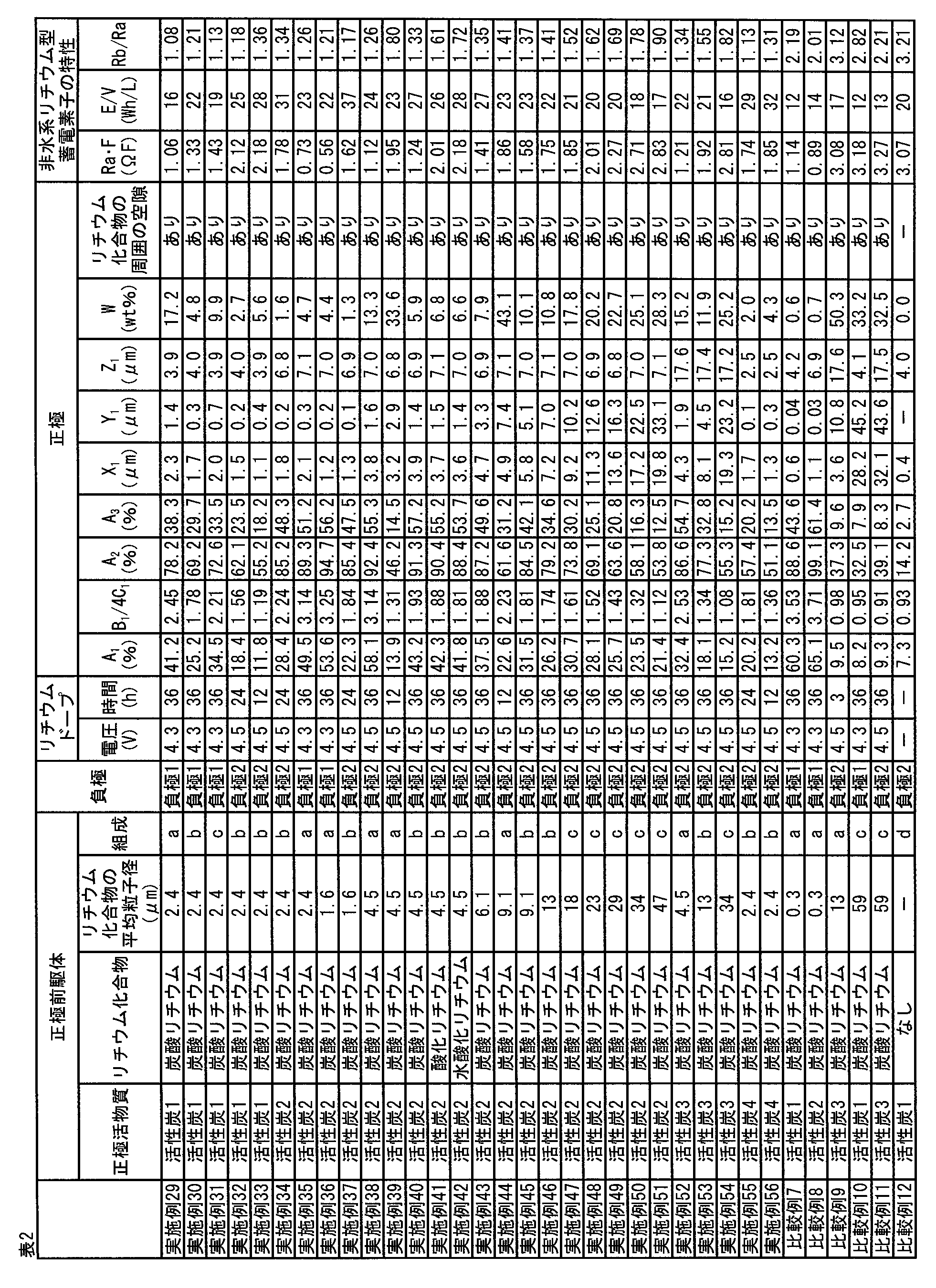
<正極活物質の調製>
[活性炭5の調製]
破砕したヤシ殻炭化物を、小型炭化炉内で、窒素雰囲気下、550℃で3時間炭化処理して炭化物を得た。得られた炭化物を賦活炉内へ入れ、1kg/hの水蒸気を予熱炉で加温した状態で上記賦活炉内へ導入し、800℃まで6時間かけて昇温して賦活した。賦活後の炭化物を取り出し、窒素雰囲気下で冷却して、賦活された活性炭を得た。得られた活性炭を10時間通水洗浄した後に水切りし、115℃に保持された電気乾燥機内で10時間乾燥した後に、ボールミルで1時間粉砕を行うことにより、活性炭5を得た。
フェノール樹脂を、窒素雰囲気下、焼成炉中600℃で2時間炭化処理した後、ボールミルにて粉砕し、分級を行って平均粒子径3.5μmの炭化物を得た。この炭化物とKOHとを、質量比1:4で混合し、窒素雰囲下、焼成炉中800℃において1時間加熱して賦活化を行い、賦活された活性炭を得た。得られた活性炭を、濃度2mol/Lに調整した希塩酸中で1時間撹拌洗浄した後、蒸留水でpH5~6の間で安定するまで煮沸洗浄した後に乾燥を行うことにより、活性炭6を得た。
フェノール樹脂を、窒素雰囲気下、焼成炉中580℃で2時間炭化処理した後、ボールミルにて粉砕し、分級を行って平均粒子径6.8μmの炭化物を得た。この炭化物とKOHとを、質量比1:5で混合し、窒素雰囲下、焼成炉中800℃において1時間加熱して賦活化を行い、賦活された活性炭を得た。得られた活性炭を、濃度2mol/Lに調整した希塩酸中で1時間撹拌洗浄を行った後、蒸留水でpH5~6の間で安定するまで煮沸洗浄した後に乾燥を行うことにより、活性炭7を得た。
フェノール樹脂を、窒素雰囲気下、焼成炉中600℃で2時間炭化処理した後、ボールミルにて粉砕し、分級を行って平均粒子径2.0μmの炭化物を得た。この炭化物とKOHとを、質量比1:4で混合し、窒素雰囲下、焼成炉中800℃において1時間加熱して賦活化を行い、賦活された活性炭を得た。得られた活性炭を、濃度2mol/Lに調整した希塩酸中で1時間撹拌洗浄した後、蒸留水でpH5~6の間で安定するまで煮沸洗浄した後に乾燥を行うことにより、活性炭8を得た。
[正極前駆体(組成b)の製造]
上記で得た活性炭1及び5~8のいずれか1つを正極活物質として用いて、下記方法で正極前駆体(組成b)を製造した。
上記で得た活性炭1及び5~7のいずれか1つを正極活物質として用いて、下記方法で正極前駆体(組成e)を製造した。
[負極3の調製]
上記で得た複合炭素材料1を負極活物質として用いて、以下のように負極3を製造した。
複合炭素材料1を85質量部、アセチレンブラックを10質量部、及びPVdF(ポリフッ化ビニリデン)を5質量部、並びにNMP(N-メチルピロリドン)を混合し、その混合物をPRIMIX社製の薄膜旋回型高速ミキサー「フィルミックス(登録商標)」を用いて、周速15m/sの条件で分散して塗工液を得た。得られた塗工液の粘度(ηb)及びTI値を東機産業社のE型粘度計TVE-35Hを用いて測定した。その結果、粘度(ηb)は2,789mPa・s、TI値は4.3であった。上記塗工液を東レエンジニアリング社製のダイコーターを用いて、厚み10μmの電解銅箔の両面に塗工速度1m/sの条件で塗工し、乾燥温度85℃で乾燥して負極3を得た。得られた負極3を、ロールプレス機を用いて圧力4kN/cm、プレス部の表面温度25℃の条件でプレスした。上記で得られた負極3の負極活物質層の厚みを、小野計器社製膜厚計Linear Gauge Sensor GS-551を用いて、負極3の任意の10か所で測定した厚みの平均値から、銅箔の厚みを引いて求めた。その結果、負極3の負極活物質層の厚みは、片面あたり100μmであった。
上記で得た複合炭素材料2を負極活物質として用いて、以下のように負極4を製造した。
複合炭素材料2を80質量部、アセチレンブラックを8質量部、及びPVdF(ポリフッ化ビニリデン)を12質量部、並びにNMP(N-メチルピロリドン)を混合し、その混合物をPRIMIX社製の薄膜旋回型高速ミキサー「フィルミックス(登録商標)」を用いて、周速15m/sの条件で分散して塗工液を得た。得られた塗工液の粘度(ηb)及びTI値を東機産業社のE型粘度計TVE-35Hを用いて測定した。その結果、粘度(ηb)は2,798mPa・s、TI値は2.7であった。上記塗工液を東レエンジニアリング社製のダイコーターを用いて、厚み10μmの電解銅箔の両面に塗工速度1m/sの条件で塗工し、乾燥温度85℃で乾燥して負極4を得た。得られた負極4を、ロールプレス機を用いて圧力4kN/cm、プレス部の表面温度25℃の条件でプレスした。上記で得られた負極4の負極活物質層の厚みを、小野計器社製膜厚計Linear Gauge Sensor GS-551を用いて、負極4の任意の10か所で測定した厚みの平均値から、銅箔の厚みを引いて求めた。その結果、負極4の負極活物質層の厚みは、片面あたり35μmであった。
<非水系リチウム型蓄電素子の作製>
[蓄電素子の組立、乾燥]
得られた両面正極前駆体(活性炭1、組成b、正極活物質層の厚みが片面あたり25μm)、両面負極4、及び片面正極前駆体(活性炭1、組成b、正極活物質層の厚みが片面あたり25μm)を10cm×10cm(100cm2)にカットした。最上面と最下面は片面正極前駆体を用い、更に両面負極4を21枚と両面正極前駆体を20枚とを用い、負極と正極前駆体との間に、厚み15μmの微多孔膜セパレータを挟んで積層した。負極と正極前駆体とに、それぞれ負極端子と正極端子を超音波溶接にて接続して電極積層体を得た。この電極積層体を、温度80℃、圧力50Paで、乾燥時間60hrの条件で真空乾燥した。乾燥した電極積層体を露点-45℃のドライ環境下にて、アルミラミネート包材から構成される外装体内に収納し、電極端子部およびボトム部の外装体3方を、温度180℃、シール時間20sec、シール圧1.0MPaの条件でヒートシールした。
アルミラミネート包材の中に収納された電極積層体に、温度25℃、露点-40℃以下のドライエアー環境下にて、実施例1と同様の非水系電解液約80gを大気圧下で注入して、リチウムドープ処理前の非水系リチウム型蓄電素子を形成した。続いて、減圧チャンバーの中に上記非水系リチウム型蓄電素子を入れ、常圧から-87kPaまで減圧した後、大気圧に戻し、5分間静置した。常圧から-87kPaまで減圧した後、大気圧に戻す操作を4回繰り返した後、蓄電素子を15分間静置した。常圧から-91kPaまで減圧した後、大気圧に戻した。同様に減圧し、大気圧に戻す操作を合計7回繰り返した(常圧から、それぞれ-95、-96、-97、-81、-97、-97、及び-97kPaまで減圧した)。以上の手順により、非水系電解液を電極積層体に含浸させた。
得られた非水系リチウム型蓄電素子に対して、東洋システム社製の充放電装置(TOSCAT-3100U)を用いて、55℃環境下、電流値0.5Aで電圧4.5Vに到達するまで定電流充電を行った後、続けて4.5V定電圧充電を1時間継続する手法により初期充電を行い、負極にリチウムドープを行った。
リチウムドープ後の非水系リチウム型蓄電素子を25℃環境下、0.5Aで電圧3.0Vに到達するまで定電流放電を行った後、3.0V定電流放電を1時間行うことにより電圧を3.0Vに調整した。続いて、非水系リチウム型蓄電素子を60℃の恒温槽に12時間保管した。
温度25℃、露点-40℃のドライエアー環境下で、エージング後の非水系リチウム型蓄電素子のアルミラミネート包材の一部を開封した。続いて、減圧チャンバーの中に上記非水系リチウム型蓄電素子を入れ、KNF社製のダイヤフラムポンプ(N816.3KT.45.18)を用いて大気圧から-80kPaまで3分間かけて減圧した後、3分間かけて大気圧に戻す操作を合計3回繰り返した。減圧シール機に非水系リチウム型蓄電素子を入れ、-90kPaに減圧した後、200℃で10秒間、0.1MPaの圧力でシールすることによりアルミラミネート包材を封止した。
上記で得た非水系リチウム型蓄電素子の内、1つは後述する静電容量、Ra・Fの測定及び高負荷充放電サイクル試験を実施した。もう1つは後述する正極のガス吸着法による細孔分布測定、正極の水銀圧入法による細孔分布測定、正極断面SEM-EDX測定及びリチウム化合物の定量を実施した。
得られた非水系リチウム型蓄電素子について、25℃に設定した恒温槽内で、富士通テレコムネットワークス株式会社製の充放電装置(5V,360A)を用いて、上述した方法により、静電容量Fと25℃における内部抵抗Raを算出し、Ra・Fとエネルギー密度E/Vとを得た。得られた結果を表4に示す。
得られた非水系リチウム型蓄電素子について、25℃に設定した恒温槽内で、富士通テレコムネットワークス株式会社製の充放電装置(5V,360A)を用いて、上述した方法により、高負荷充放電サイクル試験を実施し、高負荷充放電サイクル試験後の常温内部抵抗Rbを算出し、Rb/Raを得た。得られた結果を表4に示す。
得られた非水系リチウム型蓄電素子を露点温度-72℃のアルゴンボックス中で解体し、両面に正極活物質層が塗工された正極を10cm×5cmの大きさに切り出した。切り出した正極を、30gのジエチルカーボネート溶媒に浸し、時折ピンセットで正極を動かし、10分間洗浄した。洗浄した正極を取り出し、アルゴンボックス中で5分間風乾させ、新たに用意した30gのジエチルカーボネート溶媒に正極を浸し、上記と同様の方法にて10分間洗浄した。正極をアルゴンボックスから取り出し、真空乾燥機(ヤマト科学製、DP33)を用いて、温度25℃、圧力1kPaの条件にて20時間乾燥し、正極試料を得た。
(窒素ガス吸着測定)
上記正極試料から大きさ2cm×2cmの小片を切り出し、0.5cm×0.5cmの大きさに等分し、以下に示す条件にて細孔分布を測定した。
・測定装置:ユアサアイオニクス社製細孔分布測定装置(AUTOSORB-1 AS-1-MP)
・前処理:200℃ 20時間脱気(真空下)
・吸着ガス:窒素
・測定温度:77K
測定した細孔分布データから上述した方法により、A、B、D及びA/Bを算出した。得られた結果を表4に示す。
上記正極試料から大きさ5cm×5cmの小片を切り出し、0.5cm×0.5cmの大きさに等分し、以下に示す条件にて細孔分布を測定した。
・測定装置:カンタクローム社製細孔分布測定装置(AUTOSORB-iQ-MP)
・前処理:200℃ 20時間脱気(真空下)
・吸着ガス:二酸化炭素
・測定温度:273K
・マイクロ孔解析:NLDFT法のスリット細孔解析モデルを使用
測定した細孔分布データから上述した方法により、Cを算出した。得られた結果を表4に示す。
上記正極試料から大きさ4cm×5cmの小片を切り出し、水銀ポロシメーター(マイクロメリティクス社製オートポアIV9510型)を使用し、細孔径400μm~0.01μmの測定範囲にて、水銀圧入法による細孔分布測定を実施した。上述した方法により、Vpを算出した。細孔径0.1μm以上100μm以下の範囲に存在するLog微分細孔容積0.3mL/g以上のピーク値を有するピークを、細孔径が小さい方から順にP1、P2として、ピークトップ位置の細孔径及びLog微分細孔容積を求めた。得られた結果を表4に示す。
正極試料から1cm×1cmの小片を切り出し、日本電子製のSM-09020CPを用い、アルゴンガスを使用し、加速電圧4kV、ビーム径500μmの条件にて正極試料の面方向に垂直な断面を作製した。10Paの真空中にてスパッタリングにより表面に金をコーティングした。続いて以下に示す条件にて、大気暴露下で、切り出された正極表面のSEM、及びEDXを測定した。
・測定装置:日立ハイテクノロジー製、電解放出型走査型電子顕微鏡 FE-SEM S-4700
・加速電圧:10kV
・エミッション電流:10μA
・測定倍率:2000倍
・電子線入射角度:90°
・X線取出角度:30°
・デッドタイム:15%
・マッピング元素:C,O,F
・測定画素数:256×256ピクセル
・測定時間:60sec.
・積算回数:50回
・明るさは最大輝度に達する画素がなく、明るさの平均値が輝度40%~60%の範囲に入るように輝度及びコントラストを調整した。
上記測定した正極断面SEM及びEDXから得られた画像を、画像解析ソフト(ImageJ)を用いて上述した方法で画像解析することでY1及びZ1を算出した。その結果を表4に示す。
5cm×5cmの大きさに切り出した正極試料を、メタノールに浸し、容器に蓋をして25℃環境下、3日間静置した。その後正極を取り出し、120℃、5kPaの条件にて10時間真空乾燥した。洗浄後のメタノール溶液について、予め検量線を作成した条件にてGC/MSを測定し、ジエチルカーボネートの存在量が1%未満であることを確認した。続いて、正極重量M0を測定した後に、蒸留水に正極試料を含浸させ、容器に蓋をして45℃環境下、3日間静置した。その後正極試料を取り出し、150℃、3kPaの条件にて12時間真空乾燥した。洗浄後の蒸留水について、予め検量線を作成した条件にてGC/MSを測定し、メタノールの存在量が1%未満であることを確認した。正極重量M1を測定し、次いでスパチュラ、ブラシ、又は刷毛を用いて正極集電体上の活物質層を取り除き、正極集電体の重量M2を測定した。上述した方法に従い正極中のリチウム化合物量Wを定量した。その結果を表4に示す。
正極前駆体の正極活物質、リチウム化合物の種類及びその平均粒子径、組成、正極活物質層の厚み、負極、並びにリチウムドープの電圧と時間を、それぞれ表3に示すとおりとした他は実施例57と同様にして実施例58~78と比較例13~14の非水系リチウム型蓄電素子をそれぞれ作製し、各種の評価を行った。得られた非水系リチウム型蓄電素子の評価結果を表4に示した。
<正極前駆体(組成d)の製造>
活性炭1を87.5質量部、ケッチェンブラックを3.0質量部、PVP(ポリビニルピロリドン)を1.5質量部、及びPVdF(ポリフッ化ビニリデン)を8.0質量部、並びにNMP(N-メチルピロリドン)を混合し、その混合物をPRIMIX社製の薄膜旋回型高速ミキサー「フィルミックス(登録商標)」を用いて、周速17m/sの条件で分散して塗工液を得た。上記塗工液を東レエンジニアリング社製のダイコーターを用いて、厚み15μmのアルミニウム箔の片面又は両面に塗工速度1m/sの条件で塗工し、乾燥温度100℃で乾燥して正極前駆体(組成d)を得た。得られた正極前駆体を、ロールプレス機を用いて圧力4kN/cm、プレス部の表面温度25℃の条件でプレスした。
得られた正極前駆体(組成d)と負極活物質単位質量当たり211mAh/gに相当する金属リチウム箔を負極4の負極活物質層表面に貼り付けた負極を用いた他は実施例57と同様にして非水系リチウム型蓄電素子の組立、注液、含浸及び封止を実施した。
正極前駆体の正極活物質を活性炭5とした他は比較例15と同様にして比較例20の非水系リチウム型蓄電素子を作製し、各種の評価を行った。得られた非水系リチウム型蓄電素子の評価結果を表4に示す。


<正極前駆体の製造>
上記で得た活性炭1を正極活物質として用いて正極前駆体(組成f)を製造した。
[負極5の調製例]
平均粒子径1.1μm、BET比表面積が1,310m2/gの市販のヤシ殻活性炭150gをステンレススチールメッシュ製の籠に入れ、石炭系ピッチ(軟化点:80℃)200gを入れたステンレス製バットの上に置き、両者を電気炉(炉内有効寸法300mm×300mm×300mm)内に設置した。ヤシ殻活性炭及び石炭系ピッチを窒素雰囲気下、680℃まで8時間で昇温し、同温度で4時間保持することにより熱反応させ、複合炭素材料1aを得た。得られた複合炭素材料1aを自然冷却により60℃まで冷却した後、電気炉から取り出した。
次いで、得られた負極5について使用前負極の負極活物質層のVa、Vb、Vc、Sa、Sb、及び平均細孔径を、ユアサアイオニクス社製細孔分布測定装置(AUTOSORB-1 AS-1-MP)を用いて、窒素を吸着質として、上述した方法により測定した。その結果を表6に示す。
表5に示す基材及びその質量部、石炭系ピッチの質量部、並びに熱処理温度となるように調製した他は、負極5の調製例と同様にして、負極活物質の製造及び評価を行った。また、上記で得た負極活物質を用いて、表5に記載の塗工液となるように調製した他は、負極5の調製例と同様にして、負極の製造及び評価を行った。その結果を表5及び表6に示す。

・ヤシ殻活性炭:平均粒子径1.1μm、BET比表面積1,310m2/g
・カーボンナノ粒子1:平均粒子径7.1μm、BET比表面積1,430m2/g、1次粒子径14nm
・カーボンナノ粒子2:平均粒子径4.3μm、BET比表面積721m2/g、1次粒子径18nm
・カーボンナノ粒子3:平均粒子径6.5μm、BET比表面積413m2/g、1次粒子径35nm
・人造黒鉛:平均粒子径3.9μm、BET比表面積6.1m2/g
・天然黒鉛:平均粒子径2.1μm、BET比表面積8.7m2/g
・ピッチ:軟化点80℃の石炭系ピッチ
有機溶媒として、エチレンカーボネート(EC):メチルエチルカーボネート(EMC)=33:67(体積比)の混合溶媒を用い、全非水系電解液に対してLiN(SO2F)2及びLiPF6の濃度比が25:75(モル比)であり、かつLiN(SO2F)2及びLiPF6の濃度の和が1.2mol/Lとなるようにそれぞれの電解質塩を溶解して得た溶液を非水系電解液として使用した。
上記で得た正極前駆体(組成f)と負極5を用いて、後述する条件で複数の非水系リチウム型蓄電素子を製造した。
得られた両面負極5と片面及び両面正極前駆体(組成f)を10cm×10cm(100cm2)にカットした。最上面と最下面は片面正極前駆体を用い、更に両面負極21枚と両面正極前駆体20枚とを用い、負極5と正極前駆体との間に、厚み15μmの微多孔膜セパレータを挟んで積層した。その後、負極5と正極前駆体とに、それぞれ負極端子及び正極端子を超音波溶接にて接続して電極積層体を得た。この電極積層体を、アルミラミネート包材から構成される外装体内に収納し、電極端子部およびボトム部の外装体3方を、温度180℃、シール時間20sec、シール圧1.0MPaの条件でヒートシールし、温度80℃、圧力50Paで、乾燥時間60hrの条件で真空乾燥した。
アルミラミネート包材の中に収納された電極積層体に、大気圧下、温度25℃、露点-40℃以下のドライエアー環境下にて、上記非水系電解液を約80g注入した。続いて、電極積層体及び電解液を含む包材を減圧チャンバーの中に入れ、大気圧から-87kPaまで減圧した後、大気圧に戻し、5分間静置した。その後、大気圧から-87kPaまで減圧した後、大気圧に戻す工程を4回繰り返した後、15分間静置した。さらに、包材を大気圧から-91kPaまで減圧した後、大気圧に戻した。同様に減圧し、大気圧に戻す工程を合計7回繰り返した(大気圧から、それぞれ-95,-96,-97,-81,-97,-97,-97kPaまで減圧した)。以上の工程により、非水系電解液を電極積層体に含浸させた。
得られた非水系リチウム型蓄電素子に対して、東洋システム社製の充放電装置(TOSCAT-3100U)を用いて、25℃環境下、電流値50mAで電圧4.5Vに到達するまで定電流充電を行った後、続けて4.5V定電圧充電を24時間継続する手法により初期充電を行い、負極5にリチウムドープを行った。
リチウムドープ後の非水系リチウム型蓄電素子に対して、45℃環境下、100mAで電圧2.0Vに到達するまで定電流放電を行った後、100mAで電圧4.2Vに到達するまで定電流充電を行い、さらに4.2V定電流充電を10時間行う定電流定電圧充電工程を実施した。
エージング後の非水系リチウム型蓄電素子を、温度25℃、露点-40℃のドライエアー環境下でアルミラミネート包材の一部を開封した。続いて、減圧チャンバーの中に上記非水系リチウム型蓄電素子を入れ、KNF社製のダイヤフラムポンプ(N816.3KT.45.18)を用いて大気圧から-80kPaまで3分間かけて減圧した後、3分間かけて大気圧に戻す工程を合計3回繰り返した。その後、減圧シール機に非水系リチウム型蓄電素子を入れ、-90kPaに減圧した後、200℃で10秒間、0.1MPaの圧力でシールすることによりアルミラミネート包材を封止した。
上記で得た非水系リチウム型蓄電素子の内、1つについては後述する[静電容量、Ra・Fの測定]及び[高負荷充放電サイクル試験]を実施した。残りの非水系リチウム型蓄電素子を用いて後述する[使用後負極の負極活物質層の解析]及び[正極中のリチウム化合物の平均粒子径の測定]をそれぞれ実施した。
得られた非水系リチウム型蓄電素子について、25℃に設定した恒温槽内で、富士通テレコムネットワークス株式会社製の充放電装置(5V,360A)を用いて、上述した方法により、静電容量Fと25℃における内部抵抗Raを算出し、エネルギー密度E/VとRa・Fを得た。得られた結果を表6に示す。
得られた非水系リチウム型蓄電素子について、25℃に設定した恒温槽内で、富士通テレコムネットワークス株式会社製の充放電装置(5V,360A)を用いて、上述した方法により高負荷充放電サイクル試験を実施し、高負荷充放電サイクル試験後の内部抵抗Rbを測定して、Rb/Raを得た。得られた結果を表6に示す。
上記で得た非水系リチウム型蓄電素子の負極5について、使用後負極の負極活物質層のVa、Vb、Vc、Sa、Sb、及び平均細孔径を測定した。
得られた非水系リチウム型蓄電素子を露点温度-72℃のアルゴンボックス中で解体し、両面に正極活物質層が塗工された正極を10cm×5cmの大きさに切り出し、30gのジエチルカーボネート溶媒に浸し、時折ピンセットで正極を動かし、10分間洗浄した。続いて正極を取り出し、アルゴンボックス中で5分間風乾させ、新たに用意した30gのジエチルカーボネート溶媒に正極を浸し、前記と同様の方法にて10分間洗浄した。正極をアルゴンボックスから取り出し、真空乾燥機(ヤマト科学製、DP33)を用いて、温度25℃、圧力1kPaの条件にて20時間乾燥し、正極試料を得た。
正極試料から1cm×1cmの小片を切り出し、日本電子製のSM-09020CPを用い、アルゴンガスを使用し、加速電圧4kV、ビーム径500μmの条件にて正極試料の面方向に垂直な断面を作製した。次いで、10Paの真空中にて金をスパッタリングにより表面にコーティングした。続いて以下に示す条件にて、大気暴露下で正極表面のSEM、及びEDXを測定した。
(SEM-EDX測定条件)
・測定装置:日立ハイテクノロジー製、電解放出型走査型電子顕微鏡 FE-SEM S-4700
・加速電圧:10kV
・エミッション電流:10μA
・測定倍率:2,000倍
・電子線入射角度:90°
・X線取出角度:30°
・デッドタイム:15%
・マッピング元素:C,O,F
・測定画素数:256×256ピクセル
・測定時間:60sec.
・積算回数:50回
・明るさは最大輝度に達する画素がなく、明るさの平均値が輝度40%~60%の範囲に入るように輝度及びコントラストを調整した。
前記測定した正極断面SEM及びEDXから得られた画像を、画像解析ソフト(ImageJ)を用いて上述した方法で画像解析することでリチウム化合物の平均粒子径Y1を算出した。得られた結果を表6に示す。
正極活物質とリチウム化合物を表6に示すとおりとした他は実施例79と同様にして正極前駆体を製造した。これらの正極前駆体を用いて表6に示す負極と組み合わせた他は、実施例79と同様にして非水系リチウム型蓄電素子を製造し、評価を行った。その結果を表6、及び表7に示す。
<非水系電解液の調製>
有機溶媒として、エチレンカーボネート(EC):メチルエチルカーボネート(EMC)=33:67(体積比)の混合溶媒を用い、全非水系電解液に対してLiN(SO2F)2及びLiPF6の濃度比が25:75(モル比)であり、かつLiN(SO2F)2及びLiPF6の濃度の和が1.2mol/Lとなるようにそれぞれの電解質塩を溶解して非水系電解液を調製した。
ここで調製した非水系電解液におけるLiN(SO2F)2及びLiPF6の濃度は、それぞれ、0.3mol/L及び0.9mol/Lであった。
また、添加剤として全非水系電解液に対して1質量%となる量のビニレンカーボネートと1,3-プロパンスルトンをそれぞれ溶解して得た溶液を、非水系電解液として使用した。

実施例85と同様にして非水系リチウム型蓄電素子を製造し、これを用いて以下の方法により[使用後負極の負極活物質層の解析]を行った。
[使用後負極の負極活物質層の解析]
上記で得た非水系リチウム型蓄電素子の負極11について、使用後負極の負極活物質層のVa、Vb、Vc、Sa、Sb、及び平均細孔径を測定した。
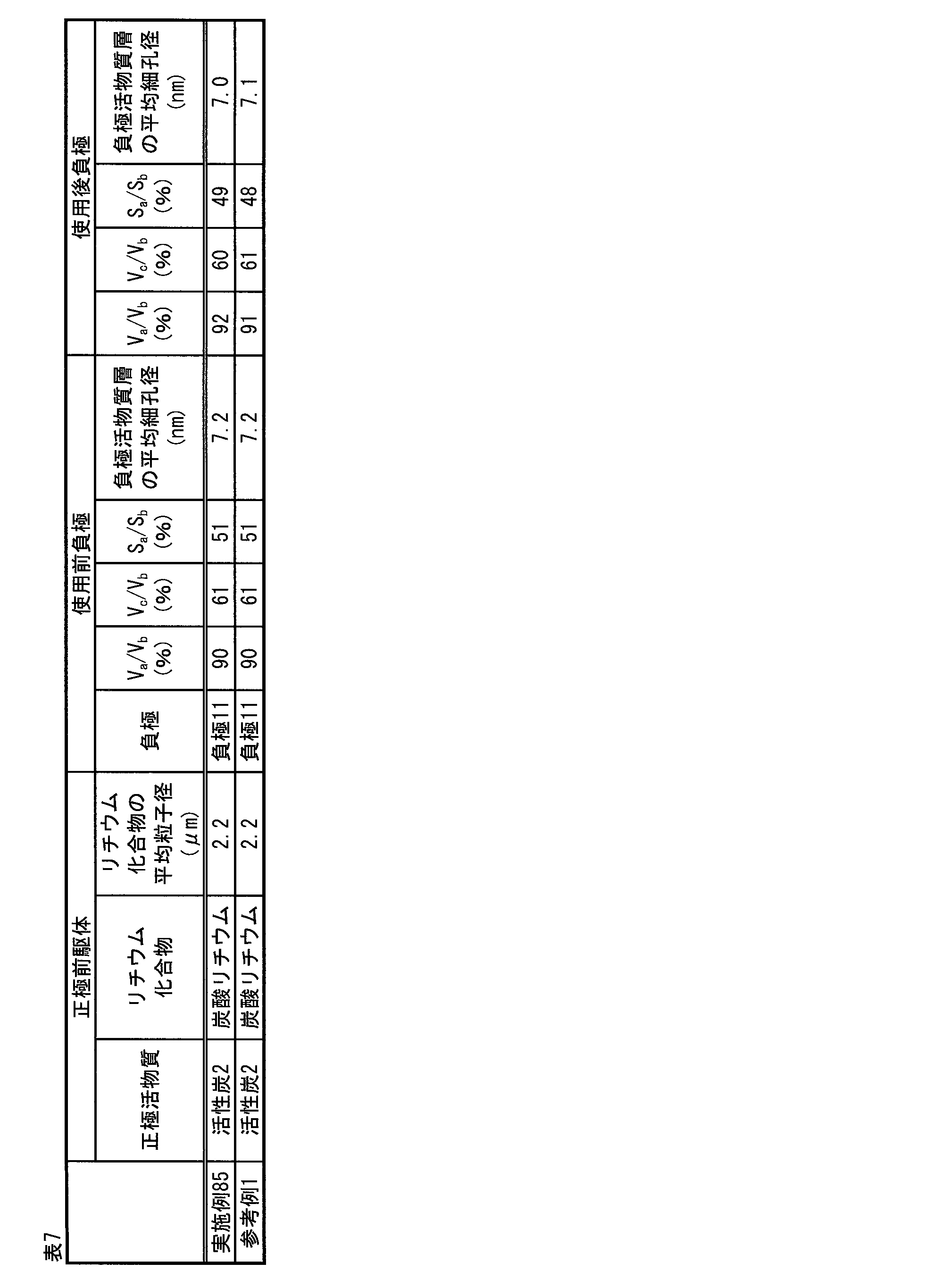
本発明の非水系リチウム型蓄電素子は、例えば、リチウムイオンキャパシタ又はリチウムイオン二次電池として適用したときに、本発明の効果が最大限に発揮されるため好ましい。
Claims (38)
- 正極、負極、セパレータ、及びリチウムイオンを含む非水系電解液を含む非水系リチウム型蓄電素子であって、
該正極は、正極集電体と、該正極集電体の片面又は両面に配置された正極活物質層とを有し、該正極活物質層は、炭素材料を含む正極活物質を含有し、
該負極は、負極集電体と、該負極集電体の片面又は両面に配置された負極活物質層とを有し、該負極活物質層は、リチウムイオンを吸蔵・放出できる負極活物質を含有し、
該正極活物質層の水銀圧入法による細孔分布を測定したとき、細孔径とLog微分細孔容積との関係を示す細孔分布曲線において、Log微分細孔容積1.0mL/g以上5.0mL/g以下のピーク値を有するピークが、細孔径0.1μm以上50μm以下の範囲で1つ以上存在し、かつ該細孔径0.1μm以上50μm以下の範囲における総積算細孔容積Vpが、0.7mL/g以上3.0mL/g以下である、
該非水系リチウム型蓄電素子。 - 前記正極活物質層の前記細孔分布曲線において、Log微分細孔容積0.5mL/g以上5.0mL/g以下のピーク値を有するピークが、前記細孔径0.1μm以上50μm以下の範囲で2つ以上存在する、請求項1に記載の非水系リチウム型蓄電素子。
- 前記正極活物質層の前記細孔分布曲線において、2つ以上のピークが、細孔径0.3μm以上20μm以下の範囲に存在する、請求項2に記載の非水系リチウム型蓄電素子。
- 前記正極は、前記正極活物質以外のリチウム化合物を含む、請求項1~3のいずれか1項に記載の非水系リチウム型蓄電素子。
- 前記リチウム化合物が、炭酸リチウム、酸化リチウム、及び水酸化リチウムからなる群から選択される1種類以上である、請求項4に記載の非水系リチウム型蓄電素子。
- 前記正極に含まれる前記リチウム化合物が、炭酸リチウムである、請求項4又は5に記載の非水系リチウム型蓄電素子。
- 前記正極に含まれる前記リチウム化合物の量が、前記正極活物質層の質量を基準として、1質量%以上50質量%以下である、請求項4~6のいずれか1項に記載の非水系リチウム型蓄電素子。
- 前記リチウム化合物の平均粒子径をY1とするとき、0.1μm≦Y1≦10μmであり、前記正極活物質の平均粒子径をZ1とするとき、2μm≦Z1≦20μmであり、かつY1<Z1である、請求項4~7のいずれか1項に記載の非水系リチウム型蓄電素子。
- 前記正極活物質層の断面SEMにおける面積0.2μm2以上250μm2以下の空隙部の割合A1が、前記正極活物質層の単位面積当たり10%以上60%以下である、請求項4~8のいずれか1項に記載の非水系リチウム型蓄電素子。
- 前記正極活物質層の断面SEMにおける面積0.2μm2以上250μm2以下の空隙部の周囲長の総和をB1、面積0.2μm2以上250μm2以下の空隙部の面積の平方根の総和をC1とするとき、1.0≦B1/4C1≦3.5を満たす、請求項9に記載の非水系リチウム型蓄電素子。
- 前記正極活物質層の断面SEMにおいて、前記正極活物質層中に含まれる前記リチウム化合物の周囲に空隙が存在し、前記空隙の平均サイズをX1とするとき、X1>Y1を満たす、請求項9又は10に記載の非水系リチウム型蓄電素子。
- 前記正極の片面当たりの窒素ガス吸着測定においてBJH法により算出した直径20Å以上500Å以下の細孔に由来する単位面積当たりのメソ孔量をA(μL/cm2)、前記窒素ガス吸着測定においてMP法により算出した直径20Å未満の細孔に由来する単位面積当たりのマイクロ孔量をB(μL/cm2)、前記正極の片面当たりの二酸化炭素ガス吸着測定においてDFT法により算出した直径7Å未満の細孔に由来する単位面積当たりのウルトラマイクロ孔量をC(μL/cm2)とするとき、0.3≦A≦5.0、0.5≦B≦10、0.05≦C≦3.0、及び0.4≦A/B≦1.5を満たす、請求項4~11のいずれか1項に記載の非水系リチウム型蓄電素子。
- 前記正極の片面当たりの窒素ガス吸着測定においてBET法により算出した単位面積当たりの比表面積をD(m2/cm2)とするとき、1≦D≦20である、請求項12に記載の非水系リチウム型蓄電素子。
- 前記正極表面のSEM-EDXにより得られる元素マッピングにおいて、明るさの平均値を基準に二値化した酸素マッピングに対するフッ素マッピングの面積重複率A2が、40%以上99%以下である、請求項1~13のいずれか1項に記載の非水系リチウム型蓄電素子。
- ブロードイオンビーム(BIB)加工した前記正極断面のSEM-EDXにより得られる元素マッピングにおいて、明るさの平均値を基準に二値化した酸素マッピングに対するフッ素マッピングの面積重複率A3が10%以上60%以下である、請求項1~14のいずれか1項に記載の非水系リチウム型蓄電素子。
- 前記負極活物質層について、QSDFT(急冷固体密度汎関数理論)により算出した20Å以上350Å以下の細孔容積が、QSDFTにより算出した0Å以上350Å以下の細孔容積の50%以上100%以下である、請求項1~15のいずれか1項に記載の非水系リチウム型蓄電素子。
- 前記負極活物質層について、QSDFTにより算出した20Å以上250Å以下の細孔容積が、QSDFTにより算出した0Å以上350Å以下の細孔容積の40%以上90%以下である、請求項16に記載の非水系リチウム型蓄電素子。
- 前記負極活物質層について、QSDFTにより算出した20Å以上350Å以下の比表面積が、QSDFTにより算出した0Å以上350Å以下の比表面積の20%以上100%以下である、請求項16又は17に記載の非水系リチウム型蓄電素子。
- 前記負極活物質層の平均細孔径が、2nm以上20nm以下である、請求項16~18のいずれか1項に記載の非水系リチウム型蓄電素子。
- 前記正極活物質は、前記炭素材料として活性炭を含有する、請求項1~19のいずれか1項に記載の非水系リチウム型蓄電素子。
- 前記活性炭は、BJH法により算出した直径20Å以上500Å以下の細孔に由来するメソ孔量をV1(cc/g)、MP法により算出した直径20Å未満の細孔に由来するマイクロ孔量をV2(cc/g)とするとき、0.3<V1≦0.8、及び0.5≦V2≦1.0を満たし、かつBET法により測定される比表面積が1,500m2/g以上3,000m2/g以下を示す、請求項20に記載の非水系リチウム型蓄電素子。
- 前記活性炭は、BJH法により算出した直径20Å以上500Å以下の細孔に由来するメソ孔量V1(cc/g)が0.8<V1≦2.5を満たし、MP法により算出した直径20Å未満の細孔に由来するマイクロ孔量V2(cc/g)が0.8<V2≦3.0を満たし、かつBET法により測定される比表面積が2,300m2/g以上4,000m2/g以下を示す、請求項20に記載の非水系リチウム型蓄電素子。
- 前記正極活物質の平均粒子径が1μm以上10μm以下である、請求項1~22のいずれか1項に記載の非水系リチウム型蓄電素子。
- 前記負極活物質のリチウムイオンのドープ量が、単位質量当たり530mAh/g以上2,500mAh/g以下である、請求項1~23のいずれか1項に記載の非水系リチウム型蓄電素子。
- 前記負極活物質のBET比表面積が100m2/g以上1,500m2/g以下である、請求項1~24のいずれか1項に記載の非水系リチウム型蓄電素子。
- 前記負極活物質のリチウムイオンのドープ量が、単位質量当たり50mAh/g以上700mAh/g以下である、請求項1~23のいずれか1項に記載の非水系リチウム型蓄電素子。
- 前記負極活物質のBET比表面積が1m2/g以上50m2/g以下である、請求項1~23及び26のいずれか1項に記載の非水系リチウム型蓄電素子。
- 前記負極活物質の平均粒子径が1μm以上10μm以下である、請求項1~23、26及び27のいずれか1項に記載の非水系リチウム型蓄電素子。
- 前記正極集電体及び前記負極集電体が、貫通孔を持たない金属箔である、請求項1~28のいずれか1項に記載の非水系リチウム型蓄電素子。
- 前記非水系リチウム型蓄電素子において、セル電圧4Vでの初期の内部抵抗をRa(Ω)、静電容量をF(F)、電力量をE(Wh)、蓄電素子の体積をV(L)とした時、以下の(a)および(b):
(a)RaとFの積Ra・Fが0.3以上3.0以下である、
(b)E/Vが15以上50以下である、
を同時に満たす、請求項1~29のいずれか1項に記載の非水系リチウム型蓄電素子。 - 前記非水系リチウム型蓄電素子において、環境温度25℃で、セル電圧を2.2Vから3.8Vまでの範囲として、300Cのレートでの充放電サイクル試験を60,000回行った後の内部抵抗をRb(Ω)、該充放電サイクル試験前の内部抵抗をRa(Ω)とした時、Rb/Raが0.90以上2.0以下である、請求項1~29のいずれか1項に記載の非水系リチウム型蓄電素子。
- 請求項1~31のいずれか1項に記載の非水系リチウム型蓄電素子を含む蓄電モジュール。
- 請求項1~31のいずれか1項に記載の非水系リチウム型蓄電素子を含む電力回生システム。
- 請求項1~31のいずれか1項に記載の非水系リチウム型蓄電素子を含む電力負荷平準化システム。
- 請求項1~31のいずれか1項に記載の非水系リチウム型蓄電素子を含む無停電電源システム。
- 請求項1~31のいずれか1項に記載の非水系リチウム型蓄電素子を含む非接触給電システム。
- 請求項1~31のいずれか1項に記載の非水系リチウム型蓄電素子を含むエナジーハーベストシステム。
- 請求項1~31のいずれか1項に記載の非水系リチウム型蓄電素子を含む蓄電システム。
Priority Applications (5)
| Application Number | Priority Date | Filing Date | Title |
|---|---|---|---|
| US16/070,422 US10468199B2 (en) | 2016-01-22 | 2017-01-20 | Nonaqueous lithium power storage element |
| EP17741575.9A EP3392895B1 (en) | 2016-01-22 | 2017-01-20 | Nonaqueous lithium power storage element |
| JP2017509053A JP6227837B1 (ja) | 2016-01-22 | 2017-01-20 | 非水系リチウム型蓄電素子 |
| KR1020187020016A KR102007130B1 (ko) | 2016-01-22 | 2017-01-20 | 비수계 리튬형 축전 소자 |
| CN201780007102.8A CN108475587B (zh) | 2016-01-22 | 2017-01-20 | 非水系锂型蓄电元件 |
Applications Claiming Priority (10)
| Application Number | Priority Date | Filing Date | Title |
|---|---|---|---|
| JP2016010895 | 2016-01-22 | ||
| JP2016-010895 | 2016-01-22 | ||
| JP2016155797 | 2016-08-08 | ||
| JP2016-155797 | 2016-08-08 | ||
| JP2016192662 | 2016-09-30 | ||
| JP2016-192662 | 2016-09-30 | ||
| JP2016192651 | 2016-09-30 | ||
| JP2016-192651 | 2016-09-30 | ||
| JP2016-192566 | 2016-09-30 | ||
| JP2016192566 | 2016-09-30 |
Publications (1)
| Publication Number | Publication Date |
|---|---|
| WO2017126698A1 true WO2017126698A1 (ja) | 2017-07-27 |
Family
ID=59362386
Family Applications (1)
| Application Number | Title | Priority Date | Filing Date |
|---|---|---|---|
| PCT/JP2017/002033 Ceased WO2017126698A1 (ja) | 2016-01-22 | 2017-01-20 | 非水系リチウム型蓄電素子 |
Country Status (7)
| Country | Link |
|---|---|
| US (1) | US10468199B2 (ja) |
| EP (1) | EP3392895B1 (ja) |
| JP (2) | JP6227837B1 (ja) |
| KR (1) | KR102007130B1 (ja) |
| CN (1) | CN108475587B (ja) |
| TW (1) | TWI628680B (ja) |
| WO (1) | WO2017126698A1 (ja) |
Cited By (6)
| Publication number | Priority date | Publication date | Assignee | Title |
|---|---|---|---|---|
| WO2019098200A1 (ja) | 2017-11-14 | 2019-05-23 | 旭化成株式会社 | 非水系リチウム型蓄電素子 |
| JP2019091792A (ja) * | 2017-11-14 | 2019-06-13 | 旭化成株式会社 | 非水系リチウム型蓄電素子 |
| EP3761418A4 (en) * | 2018-09-19 | 2021-06-16 | Lg Chem, Ltd. | LITHIUM SECONDARY BATTERY ELECTRODE WITH LIOH, METHOD FOR MANUFACTURING IT AND LITHIUM SECONDARY BATTERY WITH ELECTRODE |
| CN114094109A (zh) * | 2022-01-19 | 2022-02-25 | 深圳新宙邦科技股份有限公司 | 锂离子电池 |
| US20230197360A1 (en) * | 2020-05-26 | 2023-06-22 | Panasonic Intellectual Property Management Co., Ltd. | Electrode for electrochemical devices, and electrochemical device |
| US12051782B2 (en) | 2019-03-29 | 2024-07-30 | Asahi Kasei Kabushiki Kaisha | Method for producing non-aqueous alkali metal electricity storage element |
Families Citing this family (11)
| Publication number | Priority date | Publication date | Assignee | Title |
|---|---|---|---|---|
| US10646813B2 (en) * | 2016-09-23 | 2020-05-12 | Lehigh University | Gas separation apparatus and methods using same |
| US11521804B2 (en) * | 2018-03-14 | 2022-12-06 | Spel Technologies Private Limited | Ultra-thin lithium-ion capacitor with ultra-high power performance |
| JP2020068192A (ja) * | 2018-10-19 | 2020-04-30 | 株式会社リコー | 蓄電素子 |
| KR102328126B1 (ko) * | 2018-11-06 | 2021-11-17 | 주식회사 포스코 | 리튬 화합물, 니켈계 양극 활물질, 산화 리튬의 제조 방법, 니켈계 양극 활물질의 제조 방법, 및 이를 이용한 이차 전지 |
| KR20200051931A (ko) * | 2018-11-06 | 2020-05-14 | 주식회사 포스코 | 리튬 화합물, 니켈계 양극 활물질, 산화 리튬의 제조 방법, 니켈계 양극 활물질의 제조 방법, 및 이를 이용한 이차 전지 |
| JP7588594B2 (ja) * | 2019-09-19 | 2024-11-22 | 住友金属鉱山株式会社 | リチウムイオン二次電池用正極活物質およびリチウムイオン二次電池 |
| CN111539925B (zh) * | 2020-04-20 | 2023-08-01 | 中国科学院物理研究所 | 一种基于像素分析的锂电池负极析锂定量测试方法 |
| WO2021241334A1 (ja) * | 2020-05-29 | 2021-12-02 | パナソニックIpマネジメント株式会社 | 電気化学デバイス |
| US20250219072A1 (en) * | 2022-03-30 | 2025-07-03 | Gs Yuasa International Ltd. | Positive electrode for energy storage device, energy storage device, and energy storage apparatus |
| CN115763703B (zh) * | 2023-01-09 | 2023-06-06 | 欣旺达电动汽车电池有限公司 | 二次电池及电池包 |
| CN116297104A (zh) * | 2023-03-27 | 2023-06-23 | 郑州比克电池有限公司 | 一种锂离子电池原材料比表面积的测试方法 |
Citations (6)
| Publication number | Priority date | Publication date | Assignee | Title |
|---|---|---|---|---|
| JP2008171593A (ja) * | 2007-01-09 | 2008-07-24 | Shoei Electronics Kk | 有機電解質電池およびその製造方法 |
| JP2008181830A (ja) * | 2007-01-26 | 2008-08-07 | Sanyo Electric Co Ltd | 非水電解質二次電池 |
| JP2012006826A (ja) * | 2010-05-28 | 2012-01-12 | Saga Univ | 塊状グラフェンオキサイド、塊状グラフェン、およびこれらの製造方法 |
| JP2013201170A (ja) * | 2012-03-23 | 2013-10-03 | Aion Kk | 蓄電デバイスの電極用活性炭及び蓄電デバイスの電極用活性炭の製造方法 |
| JP2015061053A (ja) * | 2013-09-20 | 2015-03-30 | アイオン株式会社 | 蓄電デバイスの電極用活性炭及びその製造方法 |
| WO2016006632A1 (ja) * | 2014-07-09 | 2016-01-14 | 旭化成株式会社 | 非水系リチウム型蓄電素子 |
Family Cites Families (45)
| Publication number | Priority date | Publication date | Assignee | Title |
|---|---|---|---|---|
| JPS5278467A (en) | 1975-12-25 | 1977-07-01 | Agency Of Ind Science & Technol | Method of determining reference points for measurement of configuratio n |
| DE69205542T3 (de) | 1991-04-26 | 2001-06-07 | Sony Corp., Tokio/Tokyo | Sekundärbatterie mit nichtwässrigem elektrolyt. |
| JP3010781B2 (ja) | 1991-04-26 | 2000-02-21 | ソニー株式会社 | 非水電解質二次電池 |
| US5702843A (en) | 1995-05-24 | 1997-12-30 | Sharp Kabushiki Kaisha | Nonaqueous secondary battery |
| US5928812A (en) * | 1996-11-18 | 1999-07-27 | Ultralife Batteries, Inc. | High performance lithium ion polymer cells and batteries |
| JP2001167767A (ja) | 1999-12-07 | 2001-06-22 | Sony Corp | 非水電解液2次電池 |
| US6850263B2 (en) * | 2000-08-02 | 2005-02-01 | Sony Chemicals Corporation Of America | Methods of thermal transfer printing and thermal transfer printers |
| JP2004014300A (ja) | 2002-06-06 | 2004-01-15 | Sony Corp | 非水電解質電池及びその製造方法 |
| JP3960167B2 (ja) | 2002-08-29 | 2007-08-15 | 株式会社ジーエス・ユアサコーポレーション | リチウム二次電池用電極の製造方法及びリチウム二次電池の製造方法、並びに、これらを用いたリチウム二次電池用電極及びリチウム二次電池 |
| EP1576678A2 (en) * | 2002-09-10 | 2005-09-21 | California Institute Of Technology | High-capacity nanostructured silicon and lithium alloys thereof |
| JP2004362859A (ja) | 2003-06-03 | 2004-12-24 | Nissan Motor Co Ltd | リチウムイオン二次電池 |
| US20050130043A1 (en) | 2003-07-29 | 2005-06-16 | Yuan Gao | Lithium metal dispersion in electrodes |
| JP4087343B2 (ja) | 2004-02-25 | 2008-05-21 | Tdk株式会社 | リチウムイオン二次電池、及び、リチウムイオン二次電池の充電方法 |
| DE102004016766A1 (de) | 2004-04-01 | 2005-10-20 | Degussa | Nanoskalige Siliziumpartikel in negativen Elektrodenmaterialien für Lithium-Ionen-Batterien |
| US7183462B2 (en) * | 2004-07-08 | 2007-02-27 | Stine Seed Farm, Inc. | Soybean cultivar 02912951 |
| US7264206B2 (en) * | 2004-09-30 | 2007-09-04 | The Boeing Company | Leading edge flap apparatuses and associated methods |
| US7635540B2 (en) * | 2004-11-15 | 2009-12-22 | Panasonic Corporation | Negative electrode for non-aqueous electrolyte secondary battery and non-aqueous electrolyte secondary battery comprising the same |
| JP5147170B2 (ja) | 2004-12-17 | 2013-02-20 | 三洋電機株式会社 | リチウム二次電池 |
| JP4597727B2 (ja) | 2005-03-18 | 2010-12-15 | 本田技研工業株式会社 | 電気二重層キャパシタ |
| JP4971729B2 (ja) | 2006-09-04 | 2012-07-11 | 富士重工業株式会社 | リチウムイオンキャパシタ |
| JP2008177263A (ja) | 2007-01-17 | 2008-07-31 | Sanyo Electric Co Ltd | 活性炭電極及びその製造方法並びに電気二重層キャパシタ及びハイブリッドキャパシタ |
| JP5152276B2 (ja) | 2007-04-04 | 2013-02-27 | ソニー株式会社 | 多孔質炭素材料、吸着剤、充填剤、マスク、吸着シート及び担持体 |
| US8273267B2 (en) | 2007-04-09 | 2012-09-25 | Kao Corporation | Method for producing positive electrode active material for battery |
| EP2157638B1 (en) * | 2007-04-09 | 2014-01-15 | Kao Corporation | Positive electrode active material sintered body for a lithium ion secondary battery |
| US8248757B2 (en) * | 2007-11-16 | 2012-08-21 | Asahi Kasei Kabushiki Kaisha | Nonaqueous lithium-type storage element |
| JP5430849B2 (ja) * | 2007-12-27 | 2014-03-05 | 株式会社東芝 | 非水電解質電池 |
| JP2009231234A (ja) | 2008-03-25 | 2009-10-08 | Fuji Heavy Ind Ltd | 負極用炭素材料、蓄電デバイス、及び蓄電デバイス搭載品 |
| JP4998358B2 (ja) | 2008-04-08 | 2012-08-15 | ソニー株式会社 | リチウムイオン二次電池用負極およびリチウムイオン二次電池 |
| EP2355212A4 (en) * | 2008-10-27 | 2016-01-20 | Kao Corp | SINTERED LITHIUM COMPLEX OXIDE |
| KR101094937B1 (ko) | 2009-02-16 | 2011-12-15 | 삼성에스디아이 주식회사 | 원통형 이차전지 |
| US20110159382A1 (en) | 2009-05-08 | 2011-06-30 | Toru Matsui | Nonaqueous solvent, and nonaqueous electrolyte solution and nonaqueous secondary battery using the same |
| KR101767304B1 (ko) * | 2010-01-21 | 2017-08-10 | 도요타지도샤가부시키가이샤 | 리튬 2차 전지, 리튬 2차 전지의 제조 방법, 및 리튬 2차 전지를 구비하는 차량 |
| US8658312B2 (en) | 2010-03-31 | 2014-02-25 | Panasonic Corporation | Positive electrode for lithium ion battery, fabrication method thereof, and lithium ion battery using the same |
| KR101138594B1 (ko) | 2010-08-31 | 2012-05-10 | 삼성전기주식회사 | 리튬 이온 커패시터 |
| JP5278467B2 (ja) | 2011-02-21 | 2013-09-04 | 株式会社デンソー | リチウム二次電池の充電装置及び充電方法 |
| JP2012209161A (ja) | 2011-03-30 | 2012-10-25 | Toyota Central R&D Labs Inc | リチウム二次電池 |
| JP2012212629A (ja) | 2011-03-31 | 2012-11-01 | Fuji Heavy Ind Ltd | リチウムイオン蓄電デバイスの製造方法 |
| JP6006325B2 (ja) * | 2012-10-01 | 2016-10-12 | 旭化成株式会社 | 蓄電素子用電極、及び非水系リチウム型蓄電素子 |
| JP6016018B2 (ja) * | 2012-10-26 | 2016-10-26 | トヨタ自動車株式会社 | 非水電解液二次電池 |
| KR101676214B1 (ko) * | 2012-12-06 | 2016-11-29 | 아사히 가세이 가부시키가이샤 | 비수계 리튬형 축전 소자 |
| JP6218413B2 (ja) | 2013-03-29 | 2017-10-25 | 株式会社Subaru | プレドープ剤、これを用いた蓄電デバイス及びその製造方法 |
| WO2015076261A1 (ja) | 2013-11-19 | 2015-05-28 | 旭化成株式会社 | 非水系リチウム型蓄電素子 |
| EP3142173B1 (en) * | 2014-05-07 | 2019-01-02 | Eliiy Power Co., Ltd. | Positive electrode for nonaqueous electrolyte secondary batteries, and nonaqueous electrolyte secondary battery |
| JP2016012620A (ja) | 2014-06-27 | 2016-01-21 | 株式会社豊田自動織機 | プリドープ剤、リチウムイオンキャパシタ用正極、並びにリチウムイオンキャパシタ及びその製造方法 |
| EP3420607A1 (en) | 2016-02-23 | 2019-01-02 | Maxwell Technologies, Inc. | Elemental metal and carbon mixtures for energy storage devices |
-
2017
- 2017-01-20 TW TW106102070A patent/TWI628680B/zh active
- 2017-01-20 WO PCT/JP2017/002033 patent/WO2017126698A1/ja not_active Ceased
- 2017-01-20 CN CN201780007102.8A patent/CN108475587B/zh active Active
- 2017-01-20 US US16/070,422 patent/US10468199B2/en active Active
- 2017-01-20 JP JP2017509053A patent/JP6227837B1/ja active Active
- 2017-01-20 EP EP17741575.9A patent/EP3392895B1/en active Active
- 2017-01-20 KR KR1020187020016A patent/KR102007130B1/ko active Active
- 2017-10-11 JP JP2017197995A patent/JP2018061037A/ja active Pending
Patent Citations (6)
| Publication number | Priority date | Publication date | Assignee | Title |
|---|---|---|---|---|
| JP2008171593A (ja) * | 2007-01-09 | 2008-07-24 | Shoei Electronics Kk | 有機電解質電池およびその製造方法 |
| JP2008181830A (ja) * | 2007-01-26 | 2008-08-07 | Sanyo Electric Co Ltd | 非水電解質二次電池 |
| JP2012006826A (ja) * | 2010-05-28 | 2012-01-12 | Saga Univ | 塊状グラフェンオキサイド、塊状グラフェン、およびこれらの製造方法 |
| JP2013201170A (ja) * | 2012-03-23 | 2013-10-03 | Aion Kk | 蓄電デバイスの電極用活性炭及び蓄電デバイスの電極用活性炭の製造方法 |
| JP2015061053A (ja) * | 2013-09-20 | 2015-03-30 | アイオン株式会社 | 蓄電デバイスの電極用活性炭及びその製造方法 |
| WO2016006632A1 (ja) * | 2014-07-09 | 2016-01-14 | 旭化成株式会社 | 非水系リチウム型蓄電素子 |
Cited By (11)
| Publication number | Priority date | Publication date | Assignee | Title |
|---|---|---|---|---|
| WO2019098200A1 (ja) | 2017-11-14 | 2019-05-23 | 旭化成株式会社 | 非水系リチウム型蓄電素子 |
| JP2019091792A (ja) * | 2017-11-14 | 2019-06-13 | 旭化成株式会社 | 非水系リチウム型蓄電素子 |
| KR20200035453A (ko) | 2017-11-14 | 2020-04-03 | 아사히 가세이 가부시키가이샤 | 비수계 리튬형 축전 소자 |
| US11824203B2 (en) | 2017-11-14 | 2023-11-21 | Asahi Kasei Kabushiki Kaisha | Non-aqueous lithium-type electricity storage element |
| EP3761418A4 (en) * | 2018-09-19 | 2021-06-16 | Lg Chem, Ltd. | LITHIUM SECONDARY BATTERY ELECTRODE WITH LIOH, METHOD FOR MANUFACTURING IT AND LITHIUM SECONDARY BATTERY WITH ELECTRODE |
| US12278375B2 (en) | 2018-09-19 | 2025-04-15 | Lg Energy Solution, Ltd. | Lithium secondary battery electrode comprising LiOH, manufacturing method therefor, and lithium secondary battery comprising electrode |
| US12051782B2 (en) | 2019-03-29 | 2024-07-30 | Asahi Kasei Kabushiki Kaisha | Method for producing non-aqueous alkali metal electricity storage element |
| US20230197360A1 (en) * | 2020-05-26 | 2023-06-22 | Panasonic Intellectual Property Management Co., Ltd. | Electrode for electrochemical devices, and electrochemical device |
| US12051542B2 (en) * | 2020-05-26 | 2024-07-30 | Panasonic Intellectual Property Management Co., Ltd. | Electrode for electrochemical devices, and electrochemical device |
| CN114094109A (zh) * | 2022-01-19 | 2022-02-25 | 深圳新宙邦科技股份有限公司 | 锂离子电池 |
| CN114094109B (zh) * | 2022-01-19 | 2022-05-03 | 深圳新宙邦科技股份有限公司 | 锂离子电池 |
Also Published As
| Publication number | Publication date |
|---|---|
| TWI628680B (zh) | 2018-07-01 |
| EP3392895A4 (en) | 2019-03-06 |
| US20190027321A1 (en) | 2019-01-24 |
| JP2018061037A (ja) | 2018-04-12 |
| KR20180085046A (ko) | 2018-07-25 |
| US10468199B2 (en) | 2019-11-05 |
| TW201740404A (zh) | 2017-11-16 |
| EP3392895B1 (en) | 2020-03-11 |
| EP3392895A1 (en) | 2018-10-24 |
| JPWO2017126698A1 (ja) | 2018-01-25 |
| CN108475587B (zh) | 2019-07-09 |
| JP6227837B1 (ja) | 2017-11-08 |
| CN108475587A (zh) | 2018-08-31 |
| KR102007130B1 (ko) | 2019-10-01 |
Similar Documents
| Publication | Publication Date | Title |
|---|---|---|
| JP6227837B1 (ja) | 非水系リチウム型蓄電素子 | |
| JP6280288B2 (ja) | 非水系リチウム型蓄電素子 | |
| JP6774396B2 (ja) | 非水系リチウム型蓄電素子の製造方法 | |
| JP6957250B2 (ja) | 非水系リチウム型蓄電素子 | |
| JP2018056425A (ja) | 非水系リチウム型蓄電素子 | |
| WO2018030280A1 (ja) | 非水系アルカリ金属イオンキャパシタ | |
| JP6754260B2 (ja) | 非水系リチウム型蓄電素子 | |
| JP6754659B2 (ja) | 非水系リチウム型蓄電素子 | |
| JP6815150B2 (ja) | 非水系リチウム型蓄電素子 | |
| JP6792978B2 (ja) | 非水系アルカリ金属型蓄電素子 | |
| JP2018056428A (ja) | 非水系リチウム型蓄電素子用の負極 | |
| JP2019021783A (ja) | 正極前駆体、及びそれを用いた非水系リチウム型蓄電素子 | |
| JP2018056419A (ja) | 非水系リチウム型蓄電素子 | |
| JP2018056401A (ja) | 非水系リチウム型蓄電素子 | |
| JP6815148B2 (ja) | 非水系リチウム型蓄電素子 | |
| JP6829572B2 (ja) | 捲回式非水系リチウム型蓄電素子 | |
| JP2018056430A (ja) | 非水系リチウム型蓄電素子 | |
| JP6815151B2 (ja) | 非水系リチウム型蓄電素子 | |
| JP2018026391A (ja) | 非水系リチウム型蓄電素子 | |
| JP6815147B2 (ja) | 非水系リチウム型蓄電素子 | |
| JP6754655B2 (ja) | 非水系リチウム型蓄電素子 | |
| JP2018056409A (ja) | 非水系リチウム型蓄電素子 | |
| JP2018026408A (ja) | 非水系アルカリ土類金属型蓄電素子 | |
| JP6815146B2 (ja) | 非水系リチウム型蓄電素子 | |
| JP2018056431A (ja) | 非水系リチウム型蓄電素子 |
Legal Events
| Date | Code | Title | Description |
|---|---|---|---|
| ENP | Entry into the national phase |
Ref document number: 2017509053 Country of ref document: JP Kind code of ref document: A |
|
| 121 | Ep: the epo has been informed by wipo that ep was designated in this application |
Ref document number: 17741575 Country of ref document: EP Kind code of ref document: A1 |
|
| ENP | Entry into the national phase |
Ref document number: 20187020016 Country of ref document: KR Kind code of ref document: A |
|
| WWE | Wipo information: entry into national phase |
Ref document number: 1020187020016 Country of ref document: KR |
|
| WWE | Wipo information: entry into national phase |
Ref document number: 2017741575 Country of ref document: EP |
|
| NENP | Non-entry into the national phase |
Ref country code: DE |
|
| ENP | Entry into the national phase |
Ref document number: 2017741575 Country of ref document: EP Effective date: 20180719 |