WO2017126902A1 - 차량 보안 네트워크 장치 및 그 관리 방법 - Google Patents
차량 보안 네트워크 장치 및 그 관리 방법 Download PDFInfo
- Publication number
- WO2017126902A1 WO2017126902A1 PCT/KR2017/000652 KR2017000652W WO2017126902A1 WO 2017126902 A1 WO2017126902 A1 WO 2017126902A1 KR 2017000652 W KR2017000652 W KR 2017000652W WO 2017126902 A1 WO2017126902 A1 WO 2017126902A1
- Authority
- WO
- WIPO (PCT)
- Prior art keywords
- vertex
- functional elements
- asil
- edge
- vehicle
- Prior art date
- Legal status (The legal status is an assumption and is not a legal conclusion. Google has not performed a legal analysis and makes no representation as to the accuracy of the status listed.)
- Ceased
Links
Images


Classifications
-
- H—ELECTRICITY
- H04—ELECTRIC COMMUNICATION TECHNIQUE
- H04L—TRANSMISSION OF DIGITAL INFORMATION, e.g. TELEGRAPHIC COMMUNICATION
- H04L63/00—Network architectures or network communication protocols for network security
- H04L63/14—Network architectures or network communication protocols for network security for detecting or protecting against malicious traffic
- H04L63/1433—Vulnerability analysis
-
- G—PHYSICS
- G06—COMPUTING OR CALCULATING; COUNTING
- G06F—ELECTRIC DIGITAL DATA PROCESSING
- G06F21/00—Security arrangements for protecting computers, components thereof, programs or data against unauthorised activity
- G06F21/50—Monitoring users, programs or devices to maintain the integrity of platforms, e.g. of processors, firmware or operating systems
- G06F21/57—Certifying or maintaining trusted computer platforms, e.g. secure boots or power-downs, version controls, system software checks, secure updates or assessing vulnerabilities
- G06F21/577—Assessing vulnerabilities and evaluating computer system security
-
- B—PERFORMING OPERATIONS; TRANSPORTING
- B60—VEHICLES IN GENERAL
- B60R—VEHICLES, VEHICLE FITTINGS, OR VEHICLE PARTS, NOT OTHERWISE PROVIDED FOR
- B60R25/00—Fittings or systems for preventing or indicating unauthorised use or theft of vehicles
- B60R25/10—Fittings or systems for preventing or indicating unauthorised use or theft of vehicles actuating a signalling device
-
- G—PHYSICS
- G01—MEASURING; TESTING
- G01M—TESTING STATIC OR DYNAMIC BALANCE OF MACHINES OR STRUCTURES; TESTING OF STRUCTURES OR APPARATUS, NOT OTHERWISE PROVIDED FOR
- G01M17/00—Testing of vehicles
- G01M17/007—Wheeled or endless-tracked vehicles
-
- G—PHYSICS
- G07—CHECKING-DEVICES
- G07C—TIME OR ATTENDANCE REGISTERS; REGISTERING OR INDICATING THE WORKING OF MACHINES; GENERATING RANDOM NUMBERS; VOTING OR LOTTERY APPARATUS; ARRANGEMENTS, SYSTEMS OR APPARATUS FOR CHECKING NOT PROVIDED FOR ELSEWHERE
- G07C5/00—Registering or indicating the working of vehicles
- G07C5/008—Registering or indicating the working of vehicles communicating information to a remotely located station
-
- G—PHYSICS
- G07—CHECKING-DEVICES
- G07C—TIME OR ATTENDANCE REGISTERS; REGISTERING OR INDICATING THE WORKING OF MACHINES; GENERATING RANDOM NUMBERS; VOTING OR LOTTERY APPARATUS; ARRANGEMENTS, SYSTEMS OR APPARATUS FOR CHECKING NOT PROVIDED FOR ELSEWHERE
- G07C5/00—Registering or indicating the working of vehicles
- G07C5/02—Registering or indicating driving, working, idle, or waiting time only
-
- G—PHYSICS
- G07—CHECKING-DEVICES
- G07C—TIME OR ATTENDANCE REGISTERS; REGISTERING OR INDICATING THE WORKING OF MACHINES; GENERATING RANDOM NUMBERS; VOTING OR LOTTERY APPARATUS; ARRANGEMENTS, SYSTEMS OR APPARATUS FOR CHECKING NOT PROVIDED FOR ELSEWHERE
- G07C5/00—Registering or indicating the working of vehicles
- G07C5/08—Registering or indicating performance data other than driving, working, idle, or waiting time, with or without registering driving, working, idle or waiting time
-
- G—PHYSICS
- G08—SIGNALLING
- G08B—SIGNALLING SYSTEMS, e.g. PERSONAL CALLING SYSTEMS; ORDER TELEGRAPHS; ALARM SYSTEMS
- G08B21/00—Alarms responsive to a single specified undesired or abnormal condition and not otherwise provided for
- G08B21/18—Status alarms
-
- H—ELECTRICITY
- H04—ELECTRIC COMMUNICATION TECHNIQUE
- H04W—WIRELESS COMMUNICATION NETWORKS
- H04W4/00—Services specially adapted for wireless communication networks; Facilities therefor
- H04W4/30—Services specially adapted for particular environments, situations or purposes
- H04W4/40—Services specially adapted for particular environments, situations or purposes for vehicles, e.g. vehicle-to-pedestrians [V2P]
- H04W4/44—Services specially adapted for particular environments, situations or purposes for vehicles, e.g. vehicle-to-pedestrians [V2P] for communication between vehicles and infrastructures, e.g. vehicle-to-cloud [V2C] or vehicle-to-home [V2H]
-
- H—ELECTRICITY
- H04—ELECTRIC COMMUNICATION TECHNIQUE
- H04L—TRANSMISSION OF DIGITAL INFORMATION, e.g. TELEGRAPHIC COMMUNICATION
- H04L2209/00—Additional information or applications relating to cryptographic mechanisms or cryptographic arrangements for secret or secure communication H04L9/00
- H04L2209/84—Vehicles
Definitions
- the present invention relates to the field of vehicle system security, and more particularly, to a method for evaluating and managing a security level for functional elements included in a vehicle and a device for performing the same.
- the ISO 26262 standard was established to determine the risk level reasonably for each part and is provided as a risk analysis method and a countermeasure method for functional safety.
- IEC 62443 an industrial security standard, considers the feasibility of security threats but does not consider the characteristics of the vehicle environment.
- a vehicle security network design device implemented by a processor.
- the vehicle security network design apparatus is a level allocator for assigning an ASIL (Automobile Safety Integrity Level) that provides a risk management criterion for each of a plurality of functional elements in a vehicle that are at least temporarily implemented by a processor, the plurality of functional elements.
- a calculation unit that calculates device's controllability for each of the plurality of functional elements based on the connection structure between the two and the ASIL difference value and the risk of the plurality of functional elements according to the ASIL and the controllability. It may include a management unit for generating an analysis model.
- the calculator may generate a graph including a vertex corresponding to each of the plurality of functional elements and an edge indicating whether data is transmitted or received between the plurality of functional elements. . More specifically, the calculator may generate the graph including one of a one way edge and a two way edge according to a data transmission and reception direction between two functional elements connected to each other. .
- the calculator may generate an edge weight matrix representing the ASIL difference value between two functional elements included in each edge.
- the calculator may generate a weighted directed graph in which a difference value of the ASIL corresponding to each edge is displayed on a path of the edge.
- the calculator may generate a transitive closure matrix representing a sum of weight values of at least one edge included in a path between any two vertices.
- the calculation unit may correspond to a difference between the second vertex and the ASIL of the first vertex such that the difference value of the ASIL is the maximum among at least one vertex in which a path connected from the first vertex exists. It can be calculated by the controllability of the functional elements.
- the calculation unit may calculate the maximum value of the values of the first row of the transitional closed matrix corresponding to the first vertex as the controllability of the functional element corresponding to the first vertex.
- the level assigning unit assigns a likelihood of occurrence of risk to each of a plurality of functional elements in the vehicle, and the management unit assigns the plurality according to the possibility, the ASIL and the maneuverability. Create a risk analysis model of the functional elements of.
- the level assigning unit assigns the possibility according to IEC 62443 based on a threat vulnerability and a security vulnerability of each of the plurality of functional elements, and assigns the severity of the accident to each of the plurality of functional elements,
- the ASIL can be assigned in accordance with ISO 26262 based on exposure probability and controllability.
- an edge weight matrix indicating a connection state of a plurality of functional elements is calculated based on a difference between an ASIL and a connection structure between a plurality of functional elements in a vehicle, using the edge weight matrix.
- a method of calculating the steerability of a functional element in a vehicle comprising calculating the steerability of the functional element corresponding to the one vertex.
- the calculating of the edge weight matrix may include generating a vertex corresponding to the plurality of functional elements and generating a graph including an edge indicating whether data is transmitted or received between any two vertices. It may further comprise a step.
- generating the graph including the edge includes generating the graph including any one of a unidirectional edge and a bidirectional edge according to a data transmission / reception direction of the two vertices. can do.
- the generating the graph including the edges may further include generating a weighted directed graph in which ASIL difference values of two vertices corresponding to each edge are displayed on the path of each edge. Can be.
- the calculating of the manipulation possibility comprises: controlling a maximum of values of a first row of the transitional closing matrix corresponding to the first vertex to manipulate the functional element corresponding to the first vertex. Calculating the likelihood.
- the calculating of the manipulation possibility may include: calculating a difference value between a second vertex of the at least one vertex in which a path connected from the first vertex exists and the ASIL of the first vertex;
- the second vertex may be calculated based on a controllability of a functional element corresponding to a vertex, and the second vertex may represent a vertex such that a difference value between the ASIL and the first vertex is maximized.
- a program stored in a computer-readable medium may include a set of instructions for performing a vehicle security network design method. More specifically, the instruction set is a set of instructions for assigning a probability of occurrence of risk to each of a plurality of functional elements in a vehicle, and a set of instructions for assigning ASIL for risk management criteria for each of a plurality of functional elements in the vehicle. And a set of instructions for calculating a maneuverability for each of the plurality of functional elements based on a connection structure between the plurality of functional elements and the difference value of the ASIL and the plurality according to the possibility, the ASIL and the maneuverability. It may include a set of instructions for generating a risk analysis model of the functional elements of.
- FIG. 1 is a block diagram illustrating an apparatus for designing a vehicle security network, according to an exemplary embodiment.
- FIG. 2 is a flowchart illustrating a method of calculating a steerability of a functional element in a vehicle according to an exemplary embodiment.
- FIG. 3 is an exemplary diagram illustrating a graph model of in-vehicle functional elements generated by a vehicle security network design apparatus according to an exemplary embodiment.
- FIG. 4 is an exemplary diagram of a weighted directed graph generated using an edge weight matrix generated according to an embodiment.
- FIG. 5 is an exemplary diagram of a directed graph reflecting steering possibilities according to an embodiment.
- FIG. 6 is an exemplary diagram illustrating a connection relationship between functional elements included in a vehicle, according to an exemplary embodiment.
- FIG. 7A illustrates a directed graph model generated by the vehicle security network design apparatus, according to an exemplary embodiment.
- FIG. 7B may represent a graph model in which steering possibility is reflected from the directed graph model generated in FIG. 7A.
- first or second may be used to describe various components, but such terms should be interpreted only for the purpose of distinguishing one component from another component.
- first component may be referred to as a second component
- second component may also be referred to as a first component.
- the vehicle security network design apparatus 100 may include a processor.
- the vehicle security network design apparatus 110 may include a level allocator 110, a calculator 120, and a manager 130 that are at least temporarily implemented by the processor.
- the level allocator 110 may allocate an ASIL (Automobile Safety Integrity Level) that provides a risk management standard for each of a plurality of functional elements in the vehicle. More specifically, the level allocating unit 110 may allocate ASIL of each of a plurality of functional elements connected to a controller area network (CAN) of the vehicle based on Equation 1 below.
- CAN is merely an example of an intra vehicle network (IVN) managed according to embodiments, and description of CAN as an example should not be construed as limiting the scope of the present application to a specific application.
- the level assigning unit 110 may be configured to expose the exposure level reflecting the severity level of the accident and the operational situation of the vehicle according to the hazards caused by the fault or the failure of the device. Since the accident can be prevented by the driver's control even when a probability of exposure level and a mechanical malfunction occur, the ASIL level can be allocated by combining the driver's controllability. In one embodiment, the ISO 26262 standard may be used for ASIL level assignment of the level assignment unit 110.
- the level allocating unit 110 may determine the severity level of the accident as follows to allocate an ASIL grade regarding risk management criteria.
- An exemplary evaluation matrix is introduced as shown in Table 1 below.
- the level allocator 110 may determine an exposure possibility level related to a risk factor as follows.
- An exemplary evaluation matrix is introduced as shown in Table 2 below.
- the level allocating unit 110 may determine a controllability level that may escape from a risk due to the driver's control in a situation where an accident may occur as follows.
- An exemplary evaluation matrix is introduced as shown in Table 3 below.
- the level assigning unit 110 may assign them to ASIL grades in combination.
- An exemplary matrix is introduced as shown in Table 4 below.
- quality management may indicate basic quality without special requirements. From ASIL A to ASIL D, the higher the criteria required for risk management, the higher the rating.
- each of the evaluation levels described above may be represented as a graded result as shown in Table 4 above, in another embodiment, each of the evaluation levels is represented by a risk level vector having each evaluation level as an element. It will also be possible.
- the level allocator 110 may allocate a likelihood of occurrence of risk according to a predetermined criterion for each of the plurality of functional elements in the vehicle. More specifically, the level allocating unit 110 may allocate the possibility of risk generation based on Equation 2 below.
- the level allocator 110 may allocate the possibility of risk occurrence according to a combination of a likelihood of exploited vulnerability and a likelihood of realized threat as shown in Equation 2 above. More specifically, the level allocator 110 may evaluate the feasibility level of the threat as a potential possibility for the security attack, and may be determined in consideration of the human resource, the physical resource, the time required, etc. of the attacker. For example, the lower the level of knowledge and experience required for an attack, the lower the level of equipment required for an attack, and the smaller the time it takes to attack, the higher the level of feasibility of the threat. Exemplary evaluation matrices are introduced in Tables 5-6 below.
- the level allocator 110 evaluates the security vulnerability exposure level according to the openness of the target system, which can be evaluated according to how the information of the target is disclosed to the outside, how often it is used, and how to access it. have. For example, the higher the frequency of use of the target system, the more open the information, and the more open the access level, the higher the vulnerability exposure level.
- Exemplary evaluation matrices are introduced in Tables 7-8 below.
- the level allocating unit 110 may allocate a possibility of risk occurrence as shown in Table 9 below according to a combination of the assigned threat realization level and the security vulnerability exposure level.
- the calculator 120 may calculate device's controllability for each of the plurality of functional elements based on a difference between the connection structure and the ASIL class of the plurality of functional elements in the vehicle.
- the controllability calculated in this embodiment is a concept that is distinct from the controllability by the user defined in the ISO 26262 standard, and is newly defined here to take into account the controllability between the respective functional elements and the controllability of each other on the network in the vehicle. Is a factor.
- the calculator 120 generates a graph including vertices corresponding to each of the plurality of functional elements and an edge indicating whether data is transmitted or received between the plurality of functional elements.
- the edge may be any one of a one-way edge and a two-way edge according to a data transmission and reception direction between two functional elements (vertexes) connected to each other.
- the calculation unit 120 generates an edge weight matrix representing an ASIL difference value between two functional elements included in each edge.
- the calculator 120 calculates a transitive closure matrix representing a sum of weight values of at least one edge included in a path between two vertices.
- the calculation unit 120 for each vertex, for the vertex vj (0 ⁇ j ⁇ k) that can receive data from the vertex vi, that is, the vertex vi can reach, the vi and ASIL Find the grade difference from the car with the largest vj. This can be calculated by finding and taking the largest of all the values of the (i + 1) th row in the transitive closure matrix T.
- the calculation unit 120 derives the device controllability (DC) of the vertex.
- the management unit 130 may newly generate and manage a risk analysis model of the plurality of functional elements according to the ASIL, the likelihood, and the maneuverability.
- ASIL according to this embodiment may represent a grade calculated according to the ISO 26262 standard. As such, ASIL can take into account factors such as the driving situation of the vehicle and the driver's controllability that affect when a potential threat leads to an accident.
- the vehicle security network design apparatus can expect the effect of compensating the accuracy of the risk analysis for each functional element by covering the risk analysis factors that can be considered by the two standards ISO 26262 and IEC 62443.
- the management unit 130 may manage the newly analyzed vehicle security management grade as S-ASIL (Security-ASIL). Details thereof will be described later with reference to FIG. 7 and the like. In the following description, a method for calculating steering possibilities for each of the plurality of functional elements is described in detail.
- the method for calculating a maneuverability of functional components in a vehicle may include calculating an edge weight matrix according to a connection state between devices in the vehicle (210), and calculating a transitional closure matrix using the edge weight matrix. Step 220 and calculating 230 the controllability of the device using the transitional closure matrix.
- ECUs Electronic control units
- sensors and actuators in today's vehicles are networked and can send and receive various data to and from each other.
- the organic connection relationship of the plurality of devices enables a user-centered interface to the vehicle, but there is a risk of being an attack path of an external intruder. An attacker could also indirectly attack an existing well-equipped device by bypassing a vulnerability on another device.
- the vehicle security network design apparatus may generate a risk analysis model in consideration of controllability and connection between functional elements corresponding to independent devices on a network in a vehicle.
- the vehicle security network design apparatus may generate a graph model based on a connection structure between a plurality of functional elements in a vehicle.
- the functional element may represent a functional unit that is executed by one electronic component as a minimum unit of each of a plurality of functions associated with the vehicle.
- the vertex may be defined as v i ⁇ V (0 ⁇ i ⁇ k) defined as each functional element when there are k functional elements in the vehicle.
- the edge indicates a connection relationship between the plurality of functional elements and whether data is transmitted or received, and may be defined as (v i , v j ) ⁇ E (i ⁇ j, 0 ⁇ i, j ⁇ k).
- the vehicle security network design apparatus may generate a graph model including one of one way edge and two way edge according to data transmission and reception directions of two functional elements connected to each other. have.
- the vehicle security network design device implements a one way uploading system to prevent the direction of data transmission and reception between functional elements according to security threats such as hacking, and the two devices.
- the direction of communication between them can be physically fixed in a specific direction.
- such a unidirectional uploading system may be a physical and / or software function installed in a gateway or the like for routing each functional element to be connected to a network.
- a gateway or the like for routing each functional element to be connected to a network.
- the one-way uploading system is a means to maintain this directionality irreversibly.
- This one-way uploading system ensures the security level evaluated for the functional elements and the validity of its management model. Thus, while the security level is set and managed according to embodiments, the security attacker cannot access or modify the one-way uploading system.
- the unidirectional uploading system may be physically disposed between vertices vi and vertex vj, and may be a means for preventing a change in data transmission direction.
- this one-way uploading system ensures the evaluation, configuration and management effectiveness of the security level by embodiments by maintaining the edge direction in the original connection topology.
- the unidirectional uploading system may be implemented by other applications applicable to the network and communication fields, and the structure and operation of the unidirectional uploading system that can be derived by those skilled in the art without detailed description are employed in the embodiments. It should be understood as possible.
- the vehicle security network design apparatus uses the generated directed graph model to calculate an edge weight matrix W based on a difference value of the ASIL class and the connection structure between the plurality of functional elements. Can be calculated.
- the vehicle security network design device may use an undirected graph model.
- the vehicle security network design apparatus of this embodiment may generate a more accurate risk analysis model using a directed graph model reflecting the flow of data.
- the vehicle security network design apparatus may calculate the edge weight matrix W using Equations 3 and 4 below.
- the calculator in the vehicular security network design device may define a representative value A (v i ) based on the ASIL class corresponding to each functional element.
- the representative value A (v i ) is 0 if the ASIL class of vertex v i corresponding to the functional element is QM, and returns a value of 1 to 4, respectively, from ASIL A to ASIL D class.
- w i, j (0 ⁇ i, j ⁇ k) means a difference value between A (v i ) and A (v j ) with respect to the edges v i and v j , and may be defined as in Equation 4 above.
- the vehicle security network design apparatus may generate a weighted directed graph in which the difference value of the representative value A (v i ) corresponding to each edge is displayed on the path of the edge. .
- the description of the generated weighted directed graph will be described in more detail with the drawings to be added below.
- the vehicle security network design apparatus may generate a transitive closure matrix using the edge weight matrix calculated in operation 210. More specifically, the calculator in the vehicular security network design device may calculate a transitional closure matrix that represents the total sum of the weight values of all the edges included in the path between any two vertices. For example, the calculator may calculate the transitional closed matrix T as in Equations 5 and 6 below.
- the element t i, j (0 ⁇ i, j ⁇ k) of the transitional closure matrix T calculated by the vehicle security network design device is the sum of the weight values of all edges on the path between two vertices v i and v j. Can represent a sum. More specifically, the element t i, j may be defined as in Equation 6 above. In Equation 6, vertices v x to v y may represent all vertices existing on a path between two vertices v i and v j . If the value of element t i, j is absent (nil), it can indicate that no path exists between the two vertices v i and v j .
- the value of element t i, j may indicate that one or more paths exist between the two vertices v i and v j .
- the value of element t i, j is equal to the difference between A (v i ) and A (v j ), so that even if two or more paths exist, the sum of the weight values of all edges on each path is obtained. Will be the same.
- the vehicle security network design apparatus may calculate a maneuverability of the device corresponding to each of the plurality of functional elements using the transitional closure matrix. More specifically, the calculation unit in the vehicle security network design apparatus may calculate the maximum value of the values in the first row of the transitional closing matrix corresponding to the first vertex as the controllability of the functional element corresponding to the first vertex. In addition, the calculation unit may determine that the largest difference value of the ASIL level between two vertices among vertices v j (0 ⁇ j ⁇ k) in which the first vertex is reachable and a path connected from the first vertex exists. Can be represented. Also, in the case of negative numbers, the vehicle security network design device may regard the controllability as 0 because negative numbers are not meaningful in the controllability.
- FIG. 3 is an exemplary diagram illustrating a graph model of in-vehicle functional elements generated by a vehicle security network design apparatus according to an exemplary embodiment.
- an example diagram of a graph model representing 23 functional elements v 0 to v 22 included in a vehicle and a connection relationship between them is illustrated as a directed edge.
- the respective functional elements may be grouped into different functional areas in the vehicle.
- the first vertex v 0 to the third vertex v 2 may be included in the communication unit.
- the fourth vertex v 3 to the seventh vertex v 6 may be included in the infotainment.
- the eighth vertex v 7 to the fifteenth vertex v 14 may be included in the ADAS.
- the seventeenth vertex v 16 to twentieth vertex v 19 may be included in the engine.
- the brake may include the twenty-first vertices v 20 to twenty- third vertex v 22 .
- the ASIL class represented in each vertex may represent an ASIL class assigned by the level allocator in the vehicle security network design device, as described above in FIG. 1.
- each ASIL grade may be evaluated according to the ISO 26262 standard.
- FIG. 4 is an exemplary diagram of a weighted directed graph generated using an edge weight matrix generated according to an embodiment. 4, a weighted directed graph generated for a plurality of functional elements in a vehicle described in FIG. 3 is shown.
- the vehicle security network design apparatus may generate an edge weight matrix W representing a difference value of an ASIL class between two functional elements included in each edge according to Equation 3 and Equation 4.
- the edge weight matrix W for the plurality of functional elements in the vehicle of the embodiment described in FIG. 3 may be calculated as shown in Table 10 below.
- ASIL grades of the tenth vertex v 9 and the eleventh vertex v 10 may be allocated to ASIL B and ASIL D, respectively.
- the representative value A (v i ) corresponding to the ASIL grade may be determined as A (v 9 ) is 2 and A (v 10 ) is 4.
- the vehicular security network design apparatus can calculate the value of each element of the edge weight matrix W. In Table 10, the value of nil is not indicated because it does not exist.
- the weighted directed graph of FIG. 4 may include 23 vertices. In addition, it may include an edge indicating a data transmission and reception relationship of the functional elements corresponding to each of the 23 vertices.
- the edge may represent any one of a unidirectional edge and a bidirectional edge.
- the weighted directed graph may display the difference value of the representative value A (v i ) corresponding to the ASIL class of the two vertices connected along the edge on the path of each edge.
- the vehicle security network design apparatus may calculate the transitional closure matrix T using the weighted directed graph described in FIG.
- the first path p 1 may represent a path through the vertices v 9 , v 10, and v 13 .
- the second path p 2 may represent a path through the vertices v 9 , v 12, and v 13 .
- the resultant elements t i, j will be calculated by A (v j ) -A (v i ) and the result will be the same.
- the transitional closed matrix T calculated using the weighted directed graph described in FIG. 4 may be calculated as shown in Table 11 below.
- the vehicle security network design apparatus may calculate the device's controllability (DC) for each functional element by using the transitional closure matrix calculated as shown in Table 11.
- the vehicle security network design device may define the controllability of the vertex v i as DC i .
- the vehicle security network design apparatus may calculate the largest value among the data values of the tenth row as the steerability of the tenth vertex v 9 . More specifically, t 9, j described in the tenth row of the transitional closure matrix of Table 11 is 0,0,1, -1, -2, ..., 2 and the vehicle security network design device is the largest of these. You can assign the value 2 to DC 9 .
- the above description of the class of maneuverability is merely illustrative for the purpose of understanding the invention and should not be construed as limiting or limiting the scope of other embodiments.
- a more detailed maneuverability grade may be given according to the designer's needs, and an embodiment to which a simpler maneuverability grade is given will also be within the scope apparent to those skilled in the art.
- 5 shows a graph model in which the vehicle security network design apparatus calculates and reflects the controllability of all functional elements in the vehicle.
- the apparatus for designing a vehicle security network may receive data input and transfer information of Table 12 below from each module included in a predetermined vehicle.
- FIG. 6 an exemplary diagram illustrating in-vehicle wired and wireless networking defined as shown in Table 12 is shown.
- FIG. 7A illustrates a directed graph model generated by the vehicle security network design apparatus, according to an exemplary embodiment.
- a directed graph model showing connection relations and ASIL ratings among a plurality of functional elements in a wired / wireless network in a vehicle defined as shown in Table 12 and FIG. 6 is illustrated.
- FIG. 7B may represent a graph model in which steering possibility is reflected from the directed graph model generated in FIG. 7A.
- the vehicular security network design apparatus may calculate the edge weight matrix W and the transitional closure matrix T from the directed graph model described in FIG. 7A.
- the vehicle security network design apparatus may calculate the steerability DC i corresponding to each functional element using the transitional closure matrix T.
- FIG. Since the above description may be applied to the process of calculating the steering possibility, duplicate description will be omitted.
- the tire pressure sensor s 2 (DC3), radar s 3 (DC1), ultrasonic sensor s 4 (DC1), vision detection module s 5 (DC1) and anti-lock braking system c 1 (DC1) Except for the remaining functional elements, the controllability can be calculated as DC i is zero.
- the modeling algorithm for the risk analysis model described in this embodiment can be used not only to evaluate the controllability of ECUs in a vehicle, but also to selectively detect the affected device in the event of a security threat to a specific device on the network.
- the vehicle security network design device selects a functional element having a higher ASIL level among the functional elements present in a range reachable from the node in the event of a security threat at a specific node (s 2 , s 3 ), and the corresponding function.
- the elements can be displayed on the user's display to highlight them. In the case of IVN-heavy systems, manual analysis of security vulnerable functional elements will not be easy.
- the vehicle security network design apparatus of the present embodiment may expect an effect of increasing safety by checking in advance security functional elements by using a simulator to which a modeling algorithm for a risk analysis model is applied.
- the vehicle security network design apparatus is capable of generating a risk for each of a plurality of functional elements in a vehicle, an ASIL providing a risk management criterion for each of the plurality of functional elements, and a controllability for each of the plurality of functional elements ( device's controllability) can be calculated.
- the manager in the vehicle security network design device may generate a risk analysis model of the plurality of functional elements according to the likelihood, the ASIL and the maneuverability. For example, for the proposed IVN as shown in Table 12, the vehicle security network design apparatus may generate a risk analysis model as shown in Table 13 below.
- the QM may represent basic quality without special requirements. From S-ASIL A to S-ASIL D, the higher the criteria required for risk management of security threats, the higher the rating.
- Secure-ASIL is a risk analysis grade assigned by the vehicle security network design apparatus according to the present embodiment, and the risk analysis grade of each of the plurality of functional elements calculated according to the likelihood, the ASIL, and the maneuverability. Can be represented. According to the present embodiment, even in a complex in-vehicle networking system can be expected to increase the safety of the security in that the functional elements vulnerable to security threats can be evaluated based on the controllability.
- the embodiments described above may be implemented as hardware components, software components, and / or combinations of hardware components and software components.
- the devices, methods, and components described in the embodiments may include, for example, processors, controllers, arithmetic logic units (ALUs), digital signal processors, microcomputers, field programmable gates (FPGAs). It may be implemented using one or more general purpose or special purpose computers, such as an array, a programmable logic unit (PLU), a microprocessor, or any other device capable of executing and responding to instructions.
- the processing device may execute an operating system (OS) and one or more software applications running on the operating system.
- the processing device may also access, store, manipulate, process, and generate data in response to the execution of the software.
- OS operating system
- the processing device may also access, store, manipulate, process, and generate data in response to the execution of the software.
- processing device includes a plurality of processing elements and / or a plurality of types of processing elements. It can be seen that it may include.
- the processing device may include a plurality of processors or one processor and one controller.
- other processing configurations are possible, such as parallel processors.
- the software may include a computer program, code, instructions, or a combination of one or more of the above, and configure the processing device to operate as desired, or process it independently or collectively. You can command the device.
- Software and / or data may be any type of machine, component, physical device, virtual equipment, computer storage medium or device in order to be interpreted by or to provide instructions or data to the processing device. Or may be permanently or temporarily embodied in a signal wave to be transmitted.
- the software may be distributed over networked computer systems so that they may be stored or executed in a distributed manner.
- Software and data may be stored on one or more computer readable recording media.
- the method according to the embodiment may be embodied in the form of program instructions that can be executed by various computer means and recorded in a computer readable medium.
- Computer-readable media may include, alone or in combination with the program instructions, data files, data structures, and the like.
- Program instructions recorded on the computer readable medium may be those specially designed and constructed for the purposes of the embodiments, or they may be of the kind well-known and available to those having skill in the computer software arts. Examples of computer-readable recording media include magnetic media such as hard disks, floppy disks, and magnetic tape, optical media such as CD-ROMs, DVDs, and magnetic disks, such as floppy disks.
- Examples of program instructions include not only machine code generated by a compiler, but also high-level language code that can be executed by a computer using an interpreter or the like.
- the hardware device described above may be configured to operate as one or more software modules to perform the operations of the embodiments, and vice versa.
Landscapes
- Engineering & Computer Science (AREA)
- Physics & Mathematics (AREA)
- General Physics & Mathematics (AREA)
- Computer Security & Cryptography (AREA)
- General Engineering & Computer Science (AREA)
- Computer Hardware Design (AREA)
- Computing Systems (AREA)
- Computer Networks & Wireless Communication (AREA)
- Signal Processing (AREA)
- Business, Economics & Management (AREA)
- Emergency Management (AREA)
- Mechanical Engineering (AREA)
- Software Systems (AREA)
- Theoretical Computer Science (AREA)
- Small-Scale Networks (AREA)
- Traffic Control Systems (AREA)
Abstract
차량 보안 네트워크 디자인 장치는 프로세서에 의해 적어도 일시적으로 구현되는 차량 내 복수의 기능 요소들 각각에 대한 리스크 관리 기준을 제공하는 ASIL(Automobile Safety Integrity Level)을 할당하는 레벨 할당부, 상기 복수의 기능 요소들 사이의 연결 구조 및 상기 ASIL의 차이값에 기초하여 상기 복수의 기능 요소들 각각에 관한 조종 가능성(device's controllability)을 계산하는 계산부 및 상기 ASIL 및 상기 조종 가능성에 따라 상기 복수의 기능 요소들의 리스크 분석 모델을 생성하는 관리부를 포함할 수 있다.
Description
차량 시스템 보안(vehicle system security) 분야에 연관되며, 보다 구체적으로 차량에 포함되는 기능 요소(functional elements)에 대한 보안 등급의 평가 및 관리 방법 및 이를 수행하는 장치에 연관된다.
초기 자동차는 기계 기술의 집합체였으나 점차 전자 부품이 결합되면서 자동 변속에서부터 원격 제어, 네비게이션과 같은 다양한 기능 및 서비스가 가능해졌으며, 자율 운전과 같은 첨단 기술을 지원하는데 까지 발전하고 있다. 일반적인 전자제품의 부품과 달리 자동차 전자 부품의 오동작은 경우에 따라 큰 사고로 이어질 수도 있다. 차량 내 전자 부품의 비중이 늘어나면서 "기능 안전"의 중요성이 강조되고 있다. "기능 안전"이란 비합리적인 리스크(risk)가 존재하지 않는다는 의미로서, 리스크 수준이 합리적이라는 것을 의미한다. 합리적인 리스크라는 것은 오동작이 발생할 확률을 전자 부품의 등급에 따라 합리적인 수준으로 낮추어 관리한다는 의미를 나타낼 수 있다.
전자 부품 등 자동차각 부품에 따라 오동작에 따른 심각성이 다르므로 각 부품에 맞게 합리적으로 리스크 등급을 결정하는 ISO 26262 표준이 제정되어 기능 안전을 위한 리스크 분석 방법과 대응 방법으로서 제공되고 있다. 다만, 오늘날 차량 내 전자 부품의 수가 늘어남에 따라 차량 내 다른 부품 또는 다른 차량과의 네트워크로 연결이 이뤄지고 있으며, 결합으로 인한 오동작뿐만 아니라 보안 위협으로 인한 의도적인 오동작이라는 위험 요소를 고려한 리스크 분석 방법이 필요하다. 또한, 산업 보안 표준인 IEC 62443은 보안 위협의 실현 가능성을 고려하지만 차량 환경의 특성을 고려하지 못하는 실정이다.
일측에 따르면, 프로세서로 구현되는 차량 보안 네트워크 디자인 장치가 제공된다. 상기 차량 보안 네트워크 디자인 장치는 프로세서에 의해 적어도 일시적으로 구현되는 차량 내 복수의 기능 요소들 각각에 대한 리스크 관리 기준을 제공하는 ASIL(Automobile Safety Integrity Level)을 할당하는 레벨 할당부, 상기 복수의 기능 요소들 사이의 연결 구조 및 상기 ASIL의 차이값에 기초하여 상기 복수의 기능 요소들 각각에 관한 조종 가능성(device's controllability)을 계산하는 계산부 및 상기 ASIL 및 상기 조종 가능성에 따라 상기 복수의 기능 요소들의 리스크 분석 모델을 생성하는 관리부를 포함할 수 있다.
일실시예에 따르면, 상기 계산부는 상기 복수의 기능 요소들 각각에 대응하는 버텍스(vertex) 및 상기 복수의 기능 요소들 사이의 데이터 송수신 여부를 나타내는 엣지(edge)를 포함하는 그래프를 생성할 수 있다. 보다 구체적으로, 상기 계산부는 서로 연결되는 두 개의 기능 요소들 사이의 데이터 송수신 방향에 따라 단방향 엣지(one way edge) 및 양방향 엣지(two way edge) 중 어느 하나를 포함하는 상기 그래프를 생성할 수 있다.
다른 일실시예에 따르면, 상기 계산부는 각각의 엣지에 포함되는 두 개의 기능 요소들 사이의 상기 ASIL 차이값을 나타내는 엣지 웨이트 행렬을 생성할 수 있다. 또한, 상기 계산부는 상기 각각의 엣지에 대응하는 상기 ASIL의 차이값이 상기 엣지의 경로에 표시되는 웨이티드 다이렉티드 그래프(weighted, directed graph)를 생성할 수 있다.
또 다른 일실시예에 따르면, 상기 계산부는 상기 계산부는 임의의 두 버텍스 사이의 경로에 포함되는 적어도 하나의 엣지의 웨이트 값의 합을 나타내는 이행적 폐쇄 행렬(transitive closure matrix)을 생성할 수 있다. 또한, 상기 계산부는 제1 버텍스로부터 연결된 경로가 존재하는 적어도 하나의 버텍스 중 상기 ASIL의 차이값이 최대가 되도록 하는 제2 버텍스와 상기 제1 버텍스의 상기 ASIL의 차이값을 상기 제1 버텍스에 대응하는 기능 요소의 조종 가능성으로 계산할 수 있다.
또 다른 일실시예에 따르면, 상기 계산부는 상기 제1 버텍스에 대응하는 상기 이행적 폐쇄 행렬의 제1행의 값들 중 최대값을 상기 제1 버텍스에 대응하는 기능 요소의 조종 가능성으로 계산할 수 있다.
또 다른 일실시예에 따르면, 상기 레벨 할당부는 상기 차량 내 복수의 기능 요소들 각각에 대해 리스크 발생의 가능성(likelihood)을 할당하고, 상기 관리부는 상기 가능성, 상기 ASIL 및 상기 조종 가능성에 따라 상기 복수의 기능 요소들의 리스크 분석 모델을 생성할 수 있다. 상기 레벨 할당부는 상기 복수의 기능 요소들 각각에 대한 위협의 실현성 및 보안 취약점에 기초하여 IEC 62443에 따라 상기 가능성을 할당하고, 상기 복수의 기능 요소들 각각에 대한 사고의 심각도(severity), 사고의 노출 확률(probability) 및 통제 가능성에 기초하여 ISO 26262에 따라 상기 ASIL를 할당할 수 있다.
다른 일측에 따르면, 차량 내 복수의 기능 요소들 사이의 연결 구조 및 ASIL의 차이값에 기초하여 복수의 기능 요소들의 연결 상태를 나타내는 엣지 웨이트 행렬을 계산하는 단계, 상기 엣지 웨이트 행렬을 이용하여 임의의 두 버텍스 사이의 경로에 포함되는 적어도 하나의 엣지의 웨이트 값의 합을 나타내는 이행적 폐쇄 행렬을 계산하는 단계 및 제1 버텍스로부터 연결된 경로가 존재하는 적어도 하나의 버텍스 각각의 상기 ASIL을 이용하여 상기 제1 버텍스에 대응하는 기능 요소의 조종 가능성을 계산하는 단계를 포함하는 차량 내 기능 요소의 조종 가능성 계산 방법이 제공된다.
일실시예에 따르면, 상기 엣지 웨이트 행렬을 계산하는 단계는, 상기 복수의 기능 요소들에 대응하는 버텍스를 생성하고, 임의의 두 개의 버텍스 사이의 데이터 송수신 여부를 나타내는 엣지를 포함하는 그래프를 생성하는 단계를 더 포함할 수 있다.
다른 일실시예에 따르면, 상기 엣지를 포함하는 그래프를 생성하는 단계는, 상기 임의의 두 개의 버텍스의 데이터 송수신 방향에 따라 단방향 엣지 및 양방향 엣지 중 어느 하나를 포함하는 상기 그래프를 생성하는 단계를 포함할 수 있다. 또한, 상기 엣지를 포함하는 그래프를 생성하는 단계는, 각각의 엣지에 대응하는 두 버텍스의 ASIL 차이값이 상기 각각의 엣지의 경로에 표시되는 웨이티드 다이렉티드 그래프를 생성하는 단계를 더 포함할 수 있다.
또 다른 일실시예에 따르면, 상기 조종 가능성을 계산하는 단계는, 상기 제1 버텍스에 대응하는 상기 이행적 폐쇄 행렬의 제1행의 값들 중 최대값을 상기 제1 버텍스에 대응하는 기능 요소의 조종 가능성으로 계산하는 단계를 포함할 수 있다.
또 다른 일실시예에 따르면, 상기 조종 가능성을 계산하는 단계는, 상기 제1 버텍스로부터 연결된 경로가 존재하는 적어도 하나의 버텍스 중 제2 버텍스와 상기 제1 버텍스의 상기 ASIL의 차이값을 상기 제1 버텍스에 대응하는 기능 요소의 조종 가능성으로 계산하고, 상기 제2 버텍스는 상기 제1 버텍스와의 상기 ASIL의 차이값이 최대가 되도록 하는 버텍스를 나타낼 수 있다.
또 다른 일측에 따르면, 컴퓨터 판독 가능 매체에 저장된 프로그램으로서, 상기 프로그램은 차량 보안 네트워크 디자인 방법을 수행하는 명령어 세트를 포함할 수 있다. 보다 구체적으로, 상기 명령어 세트는 차량 내 복수의 기능 요소들 각각에 대해 리스크 발생의 가능성을 할당하는 명령어 세트, 상기 차량 내 복수의 기능 요소들 각각에 대해 리스크 관리 기준에 관한 ASIL을 할당하는 명령어 세트, 상기 복수의 기능 요소들 사이의 연결 구조 및 상기 ASIL의 차이값에 기초하여 상기 복수의 기능 요소들 각각에 관한 조종 가능성을 계산하는 명령어 세트 및 상기 가능성, 상기 ASIL 및 상기 조종 가능성에 따라 상기 복수의 기능 요소들의 리스크 분석 모델을 생성하는 명령어 세트를 포함할 수 있다.
도 1은 일실시예에 따른 차량 보안 네트워크 디자인 장치를 나타내는 블록도이다.
도 2는 일실시예에 따른 차량 내 기능 요소의 조종 가능성 계산 방법을 나타내는 흐름도이다.
도 3은 일실시예에 따라 차량 보안 네트워크 디자인 장치가 생성하는 차량 내 기능 요소들의 그래프 모델 예시도이다.
도 4는 일실시예에 따라 생성된 엣지 웨이트 행렬을 이용하여 생성된 웨이티드 다이렉티드 그래프의 예시도이다.
도 5는 일실시예에 따라 조종 가능성이 반영된 다이렉티드 그래프의 예시도이다.
도 6은 일실시예에 따라 차량 내 포함되는 기능 요소들의 연결 관계를 나타내는 예시도이다.
도 7a는 일실시예에 따라 차량 보안 네트워크 디자인 장치가 생성하는 다이렉티드 그래프 모델을 나타낼 수 있다.
도 7b는 상기 도 7a에서 생성된 다이렉티드 그래프 모델로부터 조종 가능성이 반영된 그래프 모델을 나타낼 수 있다.
실시예들에 대한 특정한 구조적 또는 기능적 설명들은 단지 예시를 위한 목적으로 개시된 것으로서, 다양한 형태로 변경되어 실시될 수 있다. 따라서, 실시예들은 특정한 개시형태로 한정되는 것이 아니며, 본 명세서의 범위는 기술적 사상에 포함되는 변경, 균등물, 또는 대체물을 포함한다.
제1 또는 제2 등의 용어를 다양한 구성요소들을 설명하는데 사용될 수 있지만, 이런 용어들은 하나의 구성요소를 다른 구성요소로부터 구별하는 목적으로만 해석되어야 한다. 예를 들어, 제1 구성요소는 제2 구성요소로 명명될 수 있고, 유사하게 제2 구성요소는 제1 구성요소로도 명명될 수 있다.
어떤 구성요소가 다른 구성요소에 "연결되어" 있다고 언급된 때에는, 그 다른 구성요소에 직접적으로 연결되어 있거나 또는 접속되어 있을 수도 있지만, 중간에 다른 구성요소가 존재할 수도 있다고 이해되어야 할 것이다.
단수의 표현은 문맥상 명백하게 다르게 뜻하지 않는 한, 복수의 표현을 포함한다. 본 명세서에서, "포함하다" 또는 "가지다" 등의 용어는 설시된 특징, 숫자, 단계, 동작, 구성요소, 부분품 또는 이들을 조합한 것이 존재함으로 지정하려는 것이지, 하나 또는 그 이상의 다른 특징들이나 숫자, 단계, 동작, 구성요소, 부분품 또는 이들을 조합한 것들의 존재 또는 부가 가능성을 미리 배제하지 않는 것으로 이해되어야 한다.
다르게 정의되지 않는 한, 기술적이거나 과학적인 용어를 포함해서 여기서 사용되는 모든 용어들은 해당 기술 분야에서 통상의 지식을 가진 자에 의해 일반적으로 이해되는 것과 동일한 의미를 가진다. 일반적으로 사용되는 사전에 정의되어 있는 것과 같은 용어들은 관련 기술의 문맥상 가지는 의미와 일치하는 의미를 갖는 것으로 해석되어야 하며, 본 명세서에서 명백하게 정의하지 않는 한, 이상적이거나 과도하게 형식적인 의미로 해석되지 않는다.
이하, 실시예들을 첨부된 도면들을 참조하여 상세하게 설명한다. 첨부 도면을 참조하여 설명함에 있어, 도면 부호에 관계없이 동일한 구성 요소는 동일한 참조 부호를 부여하고, 이에 대한 중복되는 설명은 생략하기로 한다.
도 1은 일실시예에 따른 차량 보안 네트워크 디자인 장치를 나타내는 블록도이다. 일실시예에 따른 차량 보안 네트워크 디자인 장치(100)는 프로세서를 포함할 수 있다. 도 1을 참조하면, 차량 보안 네트워크 디자인 장치(110)는 상기 프로세서에 의해 적어도 일시적으로 구현되는 레벨 할당부(110), 계산부(120) 및 관리부(130)를 포함할 수 있다. 레벨 할당부(110)는 차량 내 복수의 기능 요소들 각각에 대한 리스크 관리 기준을 제공하는 ASIL(Automobile Safety Integrity Level)을 할당할 수 있다. 보다 구체적으로, 레벨 할당부(110)는 아래의 수학식 1에 기초하여 차량의 CAN(Controller Area Network)에 연결되는 복수의 기능 요소들 각각의 ASIL을 할당할 수 있다. 다만, CAN은 실시예들에 따라 관리되는 차량 내부 네트워크(Intra Vehicle Network: IVN)의 예시에 불과하며, CAN을 예로 들어 설명하는 것이 본원의 범위를 특정한 응용으로 한정시키는 것으로 해석되어서는 안 된다.

레벨 할당부(110)는 기기의 오류(fault) 또는 기능 실패(failure)에 의해 발생된 위험(hazard)에 따른 사고의 심각성(severity) 레벨, 차량의 운전 상황(operational situation)을 반영한 노출 가능성(probability of exposure) 레벨 및 기계적인 오동작이 발생한 경우에도 운전자의 제어에 의해 사고가 방지될 수 있으므로, 이러한 운전자의 통제 가능성(controllability)을 조합하여 ASIL 레벨을 할당할 수 있다. 일실시예로서, 레벨 할당부(110)의 ASIL 레벨 할당에는 ISO 26262 표준이 이용될 수 있다.
레벨 할당부(110)는 리스크 관리 기준에 관한 ASIL 등급을 할당하기 위해 사고의 심각성 레벨을 아래와 같이 판단할 수 있다. 예시적인 평가 매트릭스가 아래의 표 1과 같이 소개된다.

그리고, 레벨 할당부(110)는 위험 요소에 관한 노출 가능성 레벨을 아래와 같이 판단할 수 있다. 예시적인 평가 매트릭스가 아래의 표 2와 같이 소개된다.

또한, 레벨 할당부(110)는 사고가 발생할 수 있는 상황에서 운전자의 통제로 인해 위험으로부터 벗어날 수 있는 통제가능성 레벨을 아래와 같이 판단할 수 있다. 예시적인 평가 매트릭스가 아래의 표 3과 같이 소개된다.

위와 같이, 위험에 따른 사고의 심각성 레벨, 차량의 운전 상황을 반영한 노출 가능성 레벨 및 운전자의 통제 가능성이 판단되며, 레벨 할당부(110)는 이들을 조합하여 ASIL 등급을 할당할 수 있다. 예시적인 매트릭스가 아래의 표 4와 같이 소개된다.
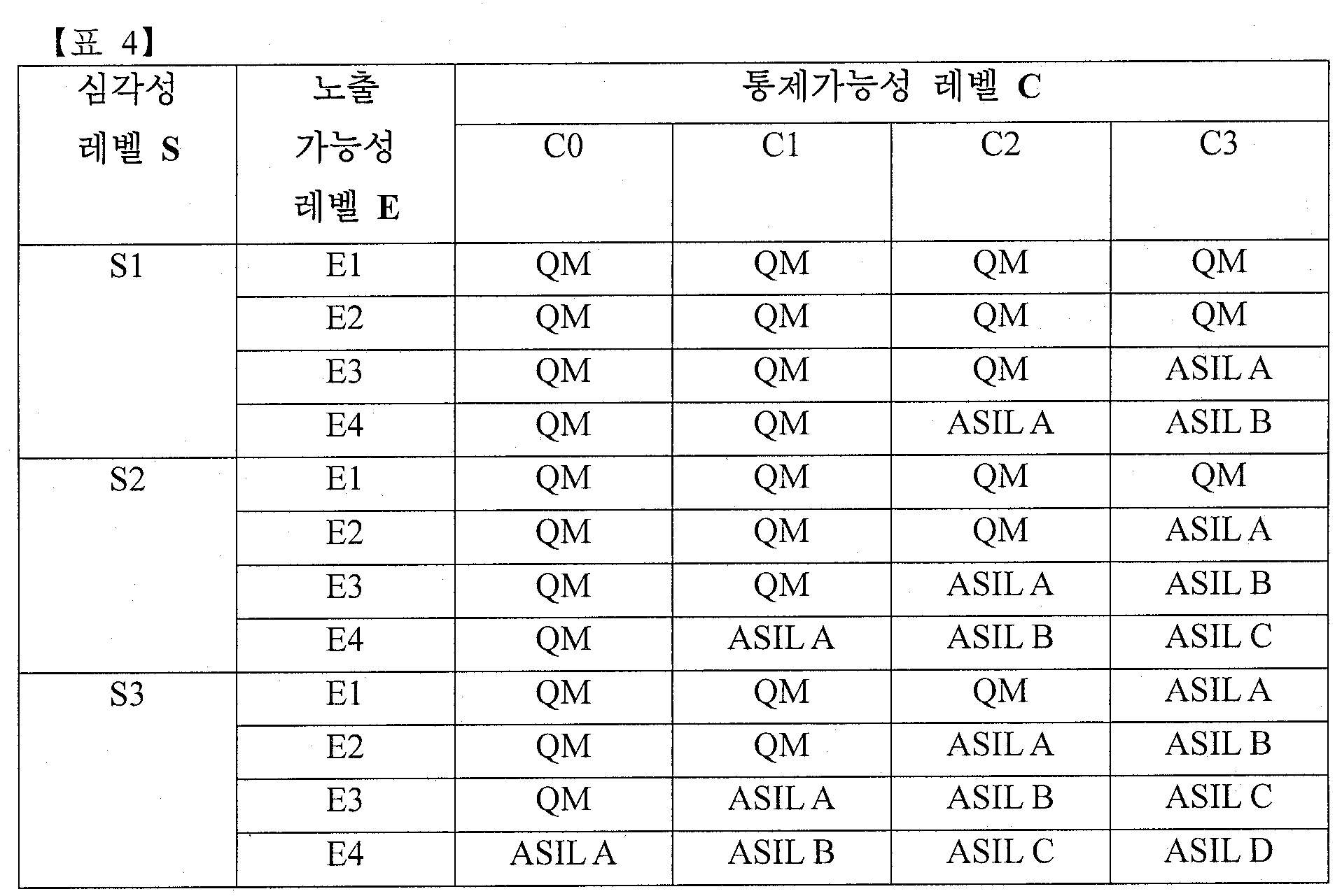
상기 표 4에서 QM(Quality Management)은 특별 요구사항이 없는 기본적인 품질을 나타낼 수 있다. ASIL A에서 ASIL D로 갈수록 리스크 관리를 위해 요구되는 기준이 높아지는 등급을 나타낼 수 있다. 위에서 설명된 각각의 평가 레벨들이 상기 표 4와 같이 등급화된 결과로 표현될 수도 있겠지만, 다른 실시예에서는 각각의 평가 레벨을 요소(element)로 하는 리스크 레벨 벡터(risk level vector)로 표현되는 것 또한 가능할 것이다.
또한, 일실시예에 따르면 레벨 할당부(110)는 차량 내 복수의 기능 요소들 각각에 대해 미리 지정된 기준에 따라 리스크 발생의 가능성(likelihood)를 할당할 수 있다. 보다 구체적으로, 레벨 할당부(110)는 아래의 수학식 2에 기초하여 리스크 발생의 가능성을 할당할 수 있다.

레벨 할당부(110)는 상기 수학식 2와 같이 보안 상의 취약점(likelihood of exploited vulnerability) 및 위협의 실현성(likelihood of realized threat)의 조합에 따라 리스크 발생의 가능성을 할당할 수 있다. 보다 구체적으로, 레벨 할당부(110)는 위협의 실현성 레벨을 보안 공격에 대한 잠재적인 가능성으로서 평가할 수 있고, 구체적으로 공격자의 인적 자원, 물적 자원, 소요 시간 등을 고려하여 정해질 수 있다. 이를테면, 공격에 요구되는 관련지식 및 경험의 수준이 낮을수록, 공격에 필요한 장비 수준이 낮을수록, 공격에 걸리는 시간이 작을수록 위협의 실현성 레벨은 높게 평가된다. 아래의 표 5 내지 표 6에서 예시적인 평가 매트릭스가 소개되었다.


또한, 레벨 할당부(110)는 보안 취약점 노출 레벨을 대상 시스템의 개방성에 따라 평가하고, 이는 공격 대상의 정보가 외부에 어떻게 공개되는지, 얼마나 자주 사용되는지, 접근하는 방법이 무엇인지에 따라 평가할 수 있다. 이를테면, 대상 시스템의 사용 빈도가 높을수록, 정보가 많이 공개되어 있을수록, 그리고 접근 수준이 개방적일수록 보안 취약점 노출 레벨은 높게 평가될 수 있다. 아래의 표 7 내지 표 8에서 예시적인 평가 매트릭스가 소개되었다.


레벨 할당부(110)는 할당된 위협의 실현성 레벨 및 보안 취약점 노출 레벨의 조합에 따라 리스크 발생의 가능성을 아래의 표 9와 같이 할당할 수 있다.

계산부(120)는 상기 차량 내 복수의 기능 요소들 사이의 연결 구조 및 상기 ASIL 등급의 차이값에 기초하여 상기 복수의 기능 요소들 각각에 관한 조종 가능성(device's controllability)를 계산할 수 있다. 본 실시예에서 계산되는 조종 가능성은 ISO 26262 표준에서 정의되는 사용자에 의한 통제 가능성과는 구분되는 개념으로서 차량 내의 네트워크 상에서 각각의 기능 요소들 사이의 연결과 서로 간의 제어 가능성을 고려하기 위해 여기서 새로이 정의되는 팩터(factor)이다.
일실시예에 따르면 계산부(120)는 복수의 기능 요소들 각각에 대응하는 버텍스(vertex) 및 상기 복수의 기능 요소들 사이의 데이터 송수신 여부를 나타내는 엣지(edge)를 포함하는 그래프를 생성한다. 여기서 엣지는 서로 연결되는 두 개의 기능 요소들(버텍스들) 사이의 데이터 송수신 방향에 따라 단방향 엣지(one way edge) 및 양방향 엣지(two way edge) 중 어느 하나일 수 있다. 그리고 계산부(120)는 각각의 엣지에 포함되는 두 개의 기능 요소들 사이의 ASIL 차이 값을 나타내는 엣지 웨이트 행렬을 생성한다. 그리고 계산부(120)는 임의의 두 버텍스 사이의 경로에 포함되는 적어도 하나의 엣지의 웨이트 값의 합을 나타내는 이행적 폐쇄 행렬(transitive closure matrix)을 계산하여 낸다. 그리고 계산부(120)는 각 버텍스에 대해, 버텍스 vi로부터 데이터를 받을 수 있는, 다시 말해 버텍스 vi가 도달할 수 있는 (reachable) 버텍스 vj (0 ≤ j < k)에 대해, vi와 ASIL 등급의 차가 가장 큰 vj와의 등급 차이를 찾는다. 이는 이행적 폐쇄 행렬(transitive closure matrix) T에서 (i+1)번째 행의 모든 값들 중 가장 큰 값 찾아 취함으로써 계산할 수 있다. 이를 계산부(120)는 버텍스에 대한 디바이스 조종 가능성(Device's controllability: DC)로 도출한다. 자세한 예는 후속하는 도면을 참고하여 설명한다.
관리부(130)는 상기 ASIL, 상기 가능성 및 상기 조종 가능성에 따라 상기 복수의 기능 요소들의 리스크 분석 모델을 새롭게 생성하여 관리할 수 있다. 본 실시예에 따른 ASIL은 ISO 26262 표준에 따라 계산된 등급을 나타낼 수 있다. 그에 따라 ASIL은 잠재적인 위협이 사고로 이어질 때 영향을 미치는 차량의 운전 상황 및 운전자의 통제 가능성과 같은 요인들까지 고려될 수 있다.
다만, ISO 26262 표준의 경우에 위협 발생에 원인이 되는 오류(fault or error) 및 기능 실패 등이 확률적으로 발생하는 것으로 가정된다. 그러나, 보안 위협은 단순한 기계적 고장과는 다르게 지능을 가진 공격자가 의도적으로 발생시킬 수 있다. 따라서, 본 실시예에 따른 리스크 발생의 가능성은 IEC 62443과 같이 보안 위협에 대한 가능성과 같은 요인들까지 고려될 수 있다. 본 실시예에 따른 차량 보안 네트워크 디자인 장치는 두 개의 표준 ISO 26262 및 IEC 62443들이 고려할 수 있는 리스크 분석 인자를 커버하여 각각의 기능 요소들에 관한 리스크 분석의 정확성을 보완하는 효과를 기대할 수 있다. 관리부(130)는 이렇게 새로이 분석되는 차량 보안 관리 등급을 S-ASIL (Security-ASIL)으로 관리할 수 있다. 자세한 내용은 도 7 등을 참조하여 예를 들어 후술한다. 이하에서 추가되는 설명에서는 복수의 기능 요소들 각각에 관한 조종 가능성을 계산하는 방법에 대해 구체적으로 기재한다.
도 2는 일실시예에 따른 차량 내 기능 요소의 조종 가능성 계산 방법을 나타내는 흐름도이다. 도 2를 참조하면, 차량 내 기능 요소의 조종 가능성 계산 방법은 차량 내 기기 사이의 연결 상태에 따라 엣지 웨이트 행렬을 계산하는 단계(210), 상기 엣지 웨이트 행렬을 이용하여 이행적 폐쇄 행렬을 계산하는 단계(220) 및 상기 이행적 폐쇄 행렬을 이용하여 기기의 조종 가능성을 계산하는 단계(230)를 포함할 수 있다.
오늘날 차량 내에 포함되는 ECU(Electronic Control Unit), 각종 센서, 액츄에이터(actuator)들은 네트워크로 연결되고, 다양한 데이터들을 서로 간에 주고 받을 수 있다. 위와 같은, 복수의 기기들의 유기적인 연결 관계는 차량에 대해 사용자 중심의 인터페이스를 구현할 수 있도록 하지만 외부 침입자의 공격 경로가 되는 위험성 또한 존재한다. 침입자는 다른 기기의 취약점을 통해 우회하여 기존의 보안이 잘 갖춰진 기기를 간접적으로 공격할 수도 있다. 위와 같은 가능성까지 고려하기 위해, 차량 보안 네트워크 디자인 장치는 차량 내의 네트워크 상에서 독립된 기기에 대응하는 기능 요소들 사이의 연결과 서로 간의 제어 가능성을 고려하여 리스크 분석 모델을 생성할 수 있다.
단계(210)에서 차량 보안 네트워크 디자인 장치는 차량 내의 복수의 기능 요소들 사이의 연결 구조에 기초하여 그래프 모델을 생성할 수 있다. 이하의 설명에서 기능 요소는 차량에 연관되는 복수의 기능 각각의 최소 단위로서, 하나의 전자 부품으로 실행되는 기능 단위를 나타낼 수 있다. 차량 보안 네트워크 디자인 장치는 복수의 기능 요소들 각각에 대응하는 버텍스(vertex) 및 상기 복수의 기능 요소들 사이의 연결 관계를 나타내는 엣지(edge)를 포함하는 그래프 모델 G=(V, E)을 생성할 수 있다.
예시적으로, 버텍스는 차량 내에 k 개의 기능 요소가 존재하는 경우에 각각의 기능 요소로서 정의되는 vi∈V(0≤i<k)로 정의될 수 있다. 또한, 엣지는 복수의 기능 요소들 사이의 연결 관계 및 데이터 송수신 여부를 나타내고, (vi, vj)∈E(i≠j, 0≤i, j<k)로 정의될 수 있다. 보다 구체적으로, 차량 보안 네트워크 디자인 장치는 서로 연결되는 두 개의 기능 요소들의 데이터 송수신 방향에 따라 단방향 엣지(one way edge) 및 양방향 엣지(two way edge) 중 어느 하나를 포함하는 그래프 모델을 생성할 수 있다.
다른 일실시예로서, 차량 보안 네트워크 디자인 장치는 해킹 등의 보안 위협에 따라 기능 요소들 사이의 데이터 송수신의 방향성이 변경되는 것을 방지하기 위해 단방향 업로딩 시스템(one way uploading system)을 구현하고, 두 기기 사이의 통신 방향을 특정 방향으로 물리적으로 고정할 수 있다.
일실시예에 따르면 이러한 단방향 업로딩 시스템은 각 기능 요소들이 네트워크로 연결되도록 라우팅 하는 게이트웨이(gateway) 등에 설치되는 물리적 및/또는 소프트웨어적 기능일 수 있다. 이를테면 버텍스 vi와 버텍스 vj로 데이터를 보낼 수 있는 단방향 연결 엣지를 갖고, 반대로 vj는 vi로 데이터를 보낼 수 없다고 하면, 상기 단방향 업로딩 시스템은 이 방향성을 비가역적으로 유지하는 수단이 된다. 이러한 단방향 업로딩 시스템은 기능 요소들에 대해 평가되는 보안 등급과, 이의 관리 모델의 유효성을 보장한다. 따라서 실시예들에 따라 보안 등급이 설정되고 관리되는 중에, 보안 공격자는 단방향 업로딩 시스템에는 접근이나 수정을 할 수 없다.
한편, 다른 일실시예에 따르면 상기 단방향 업로딩 시스템은 물리적으로 버텍스 vi와 버텍스 vj 사이에 배치되어, 데이터 전송 방향의 변경을 방지하는 수단이 될 수 있다. 네트워크 요소로서 이러한 단방향 업로딩 시스템은 원래의 연결 토폴로지에서의 엣지 디렉션을 유지함으로써 실시예들에 의한 보안 등급의 평가, 설정과 관리 유효성을 보장한다.
그 밖에도 단방향 업로딩 시스템은 네트워크 및 통신 분야에서 적용 가능한 다른 응용들에 의해 구현될 수 있으며, 자세한 설명을 하지 않더라도 해당 분야의 기술자가 도출할 수 있는 단방향 업로딩 시스템의 구조와 동작은 실시예들에서 채용될 수 있는 것으로 이해되어야 한다.
또한, 단계(210)에서 차량 보안 네트워크 디자인 장치는 생성된 다이렉티드 그래프 모델을 이용하여 복수의 기능 요소들 사이의 연결 구조 및 ASIL 등급의 차이값에 기초하여 엣지 웨이트 행렬(edge weight matrix) W를 계산할 수 있다. 차량 내 네트워크에 존재하는 복수의 기능 요소들이 ECU(Electronic Control Unit)를 통해 연결되는 구성을 이용하는 경우에, 차량 보안 네트워크 디자인 장치는 언다이렉티드(undirected) 그래프 모델을 이용할 수 있을 것이다. 그러나, 실제 차량에서는 센서에서 콘트롤러로의 데이터 송수신 또는 상기 콘트롤러에서 액추에이어터로의 데이터 송수신과 같이 단순한 연결 관계가 아닌 데이터가 송수신되는 방향이 존재할 것이다. 본 실시예의 차량 보안 네트워크 디자인 장치는 이러한 데이터의 흐름을 반영한 다이렉티드 그래프 모델을 이용하여 보다 정확한 리스크 분석 모델을 생성할 수 있다.
보다 구체적으로, 차량 보안 네트워크 디자인 장치는 아래의 수학식 3 및 수학식 4를 이용하여 엣지 웨이트 행렬 W를 계산할 수 있다.

차량 보안 네트워크 디자인 장치 내의 계산부는 각각의 기능 요소들에 대응하는 ASIL 등급에 기초하여 대표값 A(vi)를 정의할 수 있다. 예시적으로, 그러나 한정되지 않게, 대표값 A(vi)는 기능 요소에 대응하는 버텍스 vi의 ASIL 등급이 QM이면 0이고, ASIL A 내지 ASIL D 등급이면 각각 1 내지 4의 값을 반환하도록 정의될 수 있다. 또한, wi,j
(0≤i,j<k)는 엣지(vi,vj)에 대한 A(vi)와 A(vj)의 차이값을 의미하고, 상기 수학식 4와 같이 정의될 수 있다.
또한, 차량 보안 네트워크 디자인 장치는 각각의 엣지에 대응하는 대표값 A(vi)의 차이값이 상기 엣지의 경로 상에 표시되는 웨이티드 다이렉티드 그래프(weighted, directed graph)를 생성할 수 있다. 생성된 웨이티드 다이렉티드 그래프에 관한 설명은 이하에서 추가될 도면과 함께 보다 자세하게 설명될 것이다.
단계(220)에서 차량 보안 네트워크 디자인 장치는 단계(210)에서 계산된 엣지 웨이트 행렬을 이용하여 이행적 폐쇄 행렬(transitive closure matrix)을 생성할 수 있다. 보다 구체적으로, 차량 보안 네트워크 디자인 장치 내의 계산부는 임의의 두 버텍스 사이의 경로에 포함되는 모든 엣지의 웨이트 값의 총 합(total sum)을 나타내는 이행적 폐쇄 행렬을 계산할 수 있다. 예시적으로, 계산부는 아래의 수학식 5 및 수학식 6과 같이 이행적 폐쇄 행렬 T를 계산할 수 있다.

차량 보안 네트워크 디자인 장치에 의해 계산되는 이행적 폐쇄 행렬 T의 원소 ti,j(0≤i,j<k)는 두 버텍스 vi 및 vj 사이의 경로 상에 있는 모든 엣지의 웨이트 값의 총 합을 나타낼 수 있다. 보다 구체적으로, 원소 ti,j는 상기 수학식 6과 같이 정의될 수 있다. 상기 수학식 6에서 버텍스 vx 내지 vy는 두 개의 버텍스 vi 및 vj 사이의 경로 상에 존재하는 모든 버텍스들을 나타낼 수 있다. 만약 원소 ti,j의 값이 없다면(nil), 두 버텍스 vi 및 vj 사이에는 경로가 존재하지 않는다는 것을 나타낼 수 있다. 그렇지 않고 원소 ti,j의 값이 존재한다면, 두 버텍스 vi 및 vj 사이에는 하나 이상의 경로가 존재한다는 것을 나타낼 수 있다. 결과적으로, 원소 ti,j의 값은 A(vi) 및 A(vj)의 차이값과 동일하기 때문에 두 개 이상의 경로가 존재하는 경우에도 각각의 경로 상의 모든 엣지들의 웨이트 값의 총합을 동일할 것이다.
단계(230)에서 차량 보안 네트워크 디자인 장치는 상기 이행적 폐쇄 행렬을 이용하여 복수의 기능 요소 각각에 대응하는 기기의 조종 가능성을 계산할 수 있다. 보다 구체적으로, 차량 보안 네트워크 디자인 장치 내의 계산부는 제1 버텍스에 대응하는 상기 이행적 폐쇄 행렬의 제1행의 값들 중 최대값을 상기 제1 버텍스에 대응하는 기능 요소의 조종 가능성으로 계산할 수 있다. 또한, 계산부는 상기 제1 버텍스가 도달할 수 있는(reachable), 제1 버텍스로부터 연결된 경로가 존재하는 버텍스 vj(0≤j<k) 중 두 버텍스 사이의 ASIL 등급의 차이값이 가장 큰 것을 나타낼 수 있다. 또한, 조종 가능성에서 음수는 의미가 없기 때문에 음수의 경우, 차량 보안 네트워크 디자인 장치는 조종 가능성을 0으로 간주할 수 있다.
위의 설명에서 차량 보안 네트워크 디자인 장치가 리스트 분석 모델을 생성하는데 이용하는 그래프 모델 및 모델링 알고리즘이 제공되었다. 이하에서는 예시적인 차량 내 유무선 네트워킹(IVN: In-Vehicle Networking) 환경에서 리스크 분석 모델이 생성되는 과정에 대해 보다 구체적으로 설명될 것이다.
도 3은 일실시예에 따라 차량 보안 네트워크 디자인 장치가 생성하는 차량 내 기능 요소들의 그래프 모델 예시도이다. 도 3를 참조하면, 차량 내 포함되는 23개의 기능 요소 v0 내지 v22와 그들 사이의 연결 관계를 다이렉티드 엣지로 표현한 그래프 모델의 예시도가 도시된다. 예시적으로, 각각의 기능 요소들은 차량 내의 서로 다른 기능 영역 내로 그룹핑될 수 있다. 일실시예로서, 통신 유닛 내에는 제1 버텍스 v0로부터 제3 버텍스 v2가 포함될 수 있다. 다른 일실시예로서, 인포테인먼트 내에는 제4 버텍스 v3 내지 제7 버텍스 v6가 포함될 수 있다. 마찬가지로, ADAS 내에는 제8 버텍스 v7 내지 제15 버텍스 v14가 포함될 수 있다. 또한, 엔진 내에는 제17 버텍스 v16 내지 제20 버텍스 v19가 포함될 수 있다. 또한, 브레이크 내에는 제21 버텍스 v20 내지 제23 버텍스 v22가 포함될 수 있다.
각각의 버텍스 내에 표시되는 ASIL 등급은 앞서 도 1에서 설명된 바와 같이, 차량 보안 네트워크 디자인 장치 내의 레벨 할당부에 의해 할당된 ASIL 등급을 나타낼 수 있다. 예시적으로, 그러나 한정되지 않게, 각각의 ASIL 등급은 ISO 26262 표준에 따라 평가될 수 있다.
도 4는 일실시예에 따라 생성된 엣지 웨이트 행렬을 이용하여 생성된 웨이티드 다이렉티드 그래프의 예시도이다. 도 4를 참조하면, 도 3에서 설명된 차량 내의 복수의 기능 요소들에 대해 생성된 웨이티드 다이렉티드 그래프가 도시된다. 차량 보안 네트워크 디자인 장치는 상기 수학식 3 및 상기 수학식 4에 따라 각각의 엣지에 포함되는 두 개의 기능 요소들 사이의 ASIL 등급의 차이값을 나타내는 엣지 웨이트 행렬 W를 생성할 수 있다.
도 3에서 설명된 실시예의 차량 내의 복수의 기능 요소들에 관한 엣지 웨이트 행렬 W은 아래의 표 10과 같이 계산될 수 있다.

예시적으로, 제10 버텍스 v9 및 제11 버텍스 v10의 ASIL 등급은 각각 ASIL B 및 ASIL D으로 할당될 수 있다. 이 경우에, ASIL 등급에 상응하는 대표값 A(vi)는 A(v9)는 2가 되고, A(v10)는 4로 결정될 수 있다. 그에 따라, 차량 보안 네트워크 디자인 장치는 엣지 웨이트 행렬 W의 원소 w9,10=A(v10)- A(v9)를 2로서 계산할 수 있다. 마찬가지로, 차량 보안 네트워크 디자인 장치는 엣지 웨이트 행렬 W의 각각의 원소의 값을 계산해낼 수 있다. 상기 표 10에서 nil의 값은 존재하지 않는 값이므로 표시되어 있지 않다.
도 4의 웨이티드 다이렉티드 그래프는 23개의 버텍스를 포함할 수 있다. 또한, 23개의 버텍스 각각에 대응하는 기능 요소들의 데이터 송수신 관계를 나타내는 엣지를 포함할 수 있다. 상기 엣지는 단방향 엣지 및 양방향 엣지 중 어느 하나를 나타낼 수 있다. 또한, 웨이티드 다이렉티드 그래프는 엣지에 따라 연결되는 두 개의 버텍스의 ASIL 등급에 대응하는 대표값 A(vi)의 차이값을 각각의 엣지의 경로에 표시할 수 있다.
도 5는 일실시예에 따라 조종 가능성이 반영된 다이렉티드 그래프의 예시도이다. 상기 수학식 5 및 상기 수학식 6에 따라, 차량 보안 네트워크 디자인 장치는 도 4에서 설명된 웨이티드 다이렉티드 그래프를 이용하여 이행적 폐쇄 행렬 T를 계산할 수 있다. 예시적으로, 도 4에서 도시된 그래프를 참조하면, 제10 버텍스 v9로부터 제14 버텍스 v13으로 연결되는 최단 경로는 두 개가 존재할 수 있다. 보다 구체적으로, 제1 경로 p1은 버텍스 v9, v10 및 v13을 거치는 경로를 나타낼 수 있다. 또한, 제2 경로 p2는 버텍스 v9, v12 및 v13을 거치는 경로를 나타낼 수 있다.
그에 따라, 차량 보안 네트워크 디자인 장치 내의 계산부는 이행적 폐쇄 행렬 T의 원소 t9,13=w9,10 +w10,13= w9,12 +w12,
13를 2로서 계산해낼 수 있다. 앞서 기재한 바와 같이, 어떠한 경로를 따르는 경우에도 결과적으로는 원소 ti,j는 A(vj)- A(vi)에 의해 계산되어 그 결과 값은 동일할 것이다. 예시적으로, 도 4에서 설명된 웨이티드 다이렉티드 그래프를 이용하여 계산된 이행적 폐쇄 행렬 T은 아래와 표 11과 같이 계산될 수 있다.

또한, 차량 보안 네트워크 디자인 장치는 표 11과 같이 계산된 이행적 폐쇄 행렬을 이용하여 각각의 기능 요소들에 관한 조종 가능성(DC: Device's Controllability)을 계산해낼 수 있다. 차량 보안 네트워크 디자인 장치는 버텍스 vi의 조종 가능성을 DCi라고 정의할 수 있다. 예시적으로, 제10 버텍스 v9의 조종 가능성을 계산하는 경우에, 차량 보안 네트워크 디자인 장치는 제10행의 데이터 값 중 가장 큰 값을 제10 버텍스 v9의 조종 가능성으로 계산할 수 있다. 보다 구체적으로, 표 11의 이행적 폐쇄 행렬의 제10행에 기재된 t9,j는 0,0,1,-1,-2, ... ,2이며 차량 보안 네트워크 디자인 장치는 이 중 가장 큰 값인 2를 DC9으로 할당할 수 있다. 본 실시예에서, 조종 가능성은 ASIL 등급의 차이가 가장 작은 DCi=0에서부터 ASIL 등급의 차이가 가장 큰 DCi=4까지 5 가지의 등급으로 정의될 수 있다. 다만, 위와 같은 조종 가능성의 등급에 관한 설명은 발명의 이해를 돕기 위한 예시적 기재일 뿐 다른 실시예의 범위를 제한하거나 한정하는 것으로 해석되어서는 안될 것이다. 이를테면, 설계자의 필요에 따라 보다 세밀한 조종 가능성 등급이 부여될 수 있고, 보다 간편한 조종 가능성 등급이 부여되는 실시예 또한 통상의 기술자에게 자명한 범위 내에 있다고 할 것이다. 도 5에는 차량 보안 네트워크 디자인 장치가 차량 내의 모든 기능 요소들의 조종 가능성을 계산하여 반영한 그래프 모델이 도시된다.
도 6은 일실시예에 따라 차량 내 포함되는 기능 요소들의 연결 관계를 나타내는 예시도이다. 차량 보안 네트워크 디자인 장치는 미리 지정된 차량 내에 포함되는 각각의 모듈들이 서로 간에 주고 받는 데이터 정보를 아래의 표 12와 전달 입력 받을 수 있다.


도 6을 참고하면, 표 12와 같이 정의되는 차량 내 유무선 네트워킹을 도식화하는 예시도가 도시된다.
도 7a는 일실시예에 따라 차량 보안 네트워크 디자인 장치가 생성하는 다이렉티드 그래프 모델을 나타낼 수 있다. 도 7a를 참조하면, 표 12 및 도 6과 같이 정의되는 차량 내 유무선 네트워크 내의 복수의 기능 요소들 사이의 연결 관계 및 ASIL 등급이 표시되는 다이렉티드 그래프 모델이 도시된다.
도 7b는 상기 도 7a에서 생성된 다이렉티드 그래프 모델로부터 조종 가능성이 반영된 그래프 모델을 나타낼 수 있다. 본 실시예에 따른 차량 보안 네트워크 디자인 장치는 도 7a에서 설명되는 다이렉티드 그래프 모델로부터 엣지 웨이트 행렬 W 및 이행적 폐쇄 행렬 T를 계산해낼 수 있다. 또한, 차량 보안 네트워크 디자인 장치는 이행적 폐쇄 행렬 T를 이용하여 각각의 기능 요소들에 대응하는 조종 가능성 DCi를 계산해낼 수 있다. 조종 가능성을 계산하는 과정에 대해서는 앞서 기재된 설명이 그대로 적용될 수 있기 때문에 중복되는 설명은 생략하기로 한다.
도 7b를 참조하면, 타이어 압력 센서 s2(DC3), 레이더 s3(DC1), 초음파 센서 s4(DC1), 비전 감지 모듈 s5(DC1) 및 안티-락 브레이킹 시스템 c1(DC1)을 제외하고 나머지 기능 요소들에 대해서는 조종 가능성이 DCi가 0으로 계산될 수 있다.
본 실시예에서 설명되는 리스크 분석 모델에 관한 모델링 알고리즘은 차량 내의 ECU들의 조종 가능성을 평가하는 것뿐만 아니라 네트워크 상에서 특정 기기에 대한 보안 위협 발생 시 영향을 받는 기기를 선택적으로 찾아내는데 이용될 수 있다. 이를테면, 차량 보안 네트워크 디자인 장치는 특정 노드(s2, s3)에서 보안 위협이 발생하는 경우에 해당 노드로부터 도달 가능한 범위에 존재하는 기능 요소 중 ASIL 등급이 더 높은 기능 요소를 선택하고, 해당 기능 요소가 부각되도록 사용자의 디스플레이 상으로 표시할 수 있다. IVN이 방대한 시스템의 경우에는, 보안 상 취약한 기능 요소들을 하나 하나 씩 수동으로 분석하는 것은 쉽지 않을 것이다. 본 실시예의 차량 보안 네트워크 디자인 장치는 리스크 분석 모델에 관한 모델링 알고리즘이 적용된 시뮬레이터를 이용하여 보안 상 취약한 기능 요소들을 사전에 점검하여 안전성을 높이는 효과를 기대할 수 있다.
차량 보안 네트워크 디자인 장치는 차량 내 복수의 기능 요소들 각각에 대해 리스크 발생의 가능성, 상기 복수의 기능 요소들 각각에 대한 리스크 관리 기준을 제공하는 ASIL 및 상기 복수의 기능 요소들 각각에 관한 조종 가능성(device's controllability)을 계산할 수 있다. 또한, 차량 보안 네트워크 디자인 장치 내의 관리부는 상기 가능성, 상기 ASIL 및 상기 조종 가능성에 따라 상기 복수의 기능 요소들의 리스크 분석 모델을 생성할 수 있다. 예시적으로, 표 12와 같이 제안된 IVN에 대해 차량 보안 네트워크 디자인 장치는 아래의 표 13과 같이 리스크 분석 모델을 생성할 수 있다.

상기 표 13에서 QM은 특별 요구사항이 없는 기본적인 품질을 나타낼 수 있다. S-ASIL A에서 S-ASIL D로 갈수록 보안 위협에 대한 리스크 관리를 위해 요구되는 기준이 높아지는 등급을 나타낼 수 있다.
S-ASIL(Secure-ASIL)는 본 실시예에 따른 차량 보안 네트워크 디자인 장치가 할당하는 리스크 분석 등급으로서 상기 가능성, 상기 ASIL 및 상기 조종 가능성에 따라 계산된 상기 복수의 기능 요소들 각각의 리스크 분석 등급을 나타낼 수 있다. 본 실시예에 따른 은 복잡한 차량 내 네트워킹 시스템에 대해서도 조종 가능성에 기반하여 보안 위협에 취약한 기능 요소들을 평가할 수 있다는 점에서 보안의 안전성을 높이는 효과를 기대할 수 있다.
이상에서 설명된 실시예들은 하드웨어 구성요소, 소프트웨어 구성요소, 및/또는 하드웨어 구성요소 및 소프트웨어 구성요소의 조합으로 구현될 수 있다. 예를 들어, 실시예들에서 설명된 장치, 방법 및 구성요소는, 예를 들어, 프로세서, 콘트롤러, ALU(arithmetic logic unit), 디지털 신호 프로세서(digital signal processor), 마이크로컴퓨터, FPGA(field programmable gate array), PLU(programmable logic unit), 마이크로프로세서, 또는 명령(instruction)을 실행하고 응답할 수 있는 다른 어떠한 장치와 같이, 하나 이상의 범용 컴퓨터 또는 특수 목적 컴퓨터를 이용하여 구현될 수 있다. 처리 장치는 운영 체제(OS) 및 상기 운영 체제 상에서 수행되는 하나 이상의 소프트웨어 애플리케이션을 수행할 수 있다. 또한, 처리 장치는 소프트웨어의 실행에 응답하여, 데이터를 접근, 저장, 조작, 처리 및 생성할 수도 있다. 이해의 편의를 위하여, 처리 장치는 하나가 사용되는 것으로 설명된 경우도 있지만, 해당 기술분야에서 통상의 지식을 가진 자는, 처리 장치가 복수 개의 처리 요소(processing element) 및/또는 복수 유형의 처리 요소를 포함할 수 있음을 알 수 있다. 예를 들어, 처리 장치는 복수 개의 프로세서 또는 하나의 프로세서 및 하나의 콘트롤러를 포함할 수 있다. 또한, 병렬 프로세서(parallel processor)와 같은, 다른 처리 구성(processing configuration)도 가능하다.
소프트웨어는 컴퓨터 프로그램(computer program), 코드(code), 명령(instruction), 또는 이들 중 하나 이상의 조합을 포함할 수 있으며, 원하는 대로 동작하도록 처리 장치를 구성하거나 독립적으로 또는 결합적으로(collectively) 처리 장치를 명령할 수 있다. 소프트웨어 및/또는 데이터는, 처리 장치에 의하여 해석되거나 처리 장치에 명령 또는 데이터를 제공하기 위하여, 어떤 유형의 기계, 구성요소(component), 물리적 장치, 가상 장치(virtual equipment), 컴퓨터 저장 매체 또는 장치, 또는 전송되는 신호 파(signal wave)에 영구적으로, 또는 일시적으로 구체화(embody)될 수 있다. 소프트웨어는 네트워크로 연결된 컴퓨터 시스템 상에 분산되어서, 분산된 방법으로 저장되거나 실행될 수도 있다. 소프트웨어 및 데이터는 하나 이상의 컴퓨터 판독 가능 기록 매체에 저장될 수 있다.
실시예에 따른 방법은 다양한 컴퓨터 수단을 통하여 수행될 수 있는 프로그램 명령 형태로 구현되어 컴퓨터 판독 가능 매체에 기록될 수 있다. 컴퓨터 판독 가능 매체는 프로그램 명령, 데이터 파일, 데이터 구조 등을 단독으로 또는 조합하여 포함할 수 있다. 컴퓨터 판독 가능 매체에 기록되는 프로그램 명령은 실시예를 위하여 특별히 설계되고 구성된 것들이거나 컴퓨터 소프트웨어 당업자에게 공지되어 사용 가능한 것일 수도 있다. 컴퓨터 판독 가능 기록 매체의 예에는 하드 디스크, 플로피 디스크 및 자기 테이프와 같은 자기 매체(magnetic media), CD-ROM, DVD와 같은 광기록 매체(optical media), 플롭티컬 디스크(floptical disk)와 같은 자기-광 매체(magneto-optical media), 및 롬(ROM), 램(RAM), 플래시 메모리 등과 같은 프로그램 명령을 저장하고 수행하도록 특별히 구성된 하드웨어 장치가 포함된다. 프로그램 명령의 예에는 컴파일러에 의해 만들어지는 것과 같은 기계어 코드뿐만 아니라 인터프리터 등을 사용해서 컴퓨터에 의해서 실행될 수 있는 고급 언어 코드를 포함한다. 상기된 하드웨어 장치는 실시예의 동작을 수행하기 위해 하나 이상의 소프트웨어 모듈로서 작동하도록 구성될 수 있으며, 그 역도 마찬가지이다.
이상과 같이 실시예들이 비록 한정된 도면에 의해 설명되었으나, 해당 기술분야에서 통상의 지식을 가진 자라면 상기를 기초로 다양한 기술적 수정 및 변형을 적용할 수 있다. 예를 들어, 설명된 기술들이 설명된 방법과 다른 순서로 수행되거나, 및/또는 설명된 시스템, 구조, 장치, 회로 등의 구성요소들이 설명된 방법과 다른 형태로 결합 또는 조합되거나, 다른 구성요소 또는 균등물에 의하여 대치되거나 치환되더라도 적절한 결과가 달성될 수 있다.
Claims (17)
- 프로세서로 구현되는:차량 내 복수의 기능 요소들 각각에 대한 리스크 관리 기준을 제공하는 ASIL(Automobile Safety Integrity Level)을 할당하는 레벨 할당부;상기 복수의 기능 요소들 사이의 연결 구조 및 상기 ASIL의 차이값에 기초하여 상기 복수의 기능 요소들 각각에 관한 조종 가능성(device's controllability)을 계산하는 계산부; 및상기 ASIL 및 상기 조종 가능성에 따라 상기 복수의 기능 요소들의 리스크 분석 모델을 설립하여 관리하는 관리부를 포함하는 차량 보안 네트워크 디자인 장치.
- 제1항에 있어서,상기 계산부는 상기 복수의 기능 요소들 각각에 대응하는 버텍스(vertex) 및 상기 복수의 기능 요소들 사이의 데이터 송수신 여부를 나타내는 엣지(edge)를 포함하는 그래프를 생성하는 차량 보안 네트워크 디자인 장치.
- 제2항에 있어서,상기 계산부는 서로 연결되는 두 개의 기능 요소들 사이의 데이터 송수신 방향에 따라 단방향 엣지(one way edge) 및 양방향 엣지(two way edge) 중 어느 하나를 포함하는 상기 그래프를 생성하는 차량 보안 네트워크 디자인 장치.
- 제2항에 있어서,상기 계산부는 각각의 엣지에 포함되는 두 개의 기능 요소들 사이의 상기 ASIL 차이값을 나타내는 엣지 웨이트 행렬을 생성하는 차량 보안 네트워크 디자인 장치.
- 제4항에 있어서,상기 계산부는 상기 각각의 엣지에 대응하는 상기 ASIL의 차이값이 상기 엣지의 경로에 표시되는 웨이티드 다이렉티드 그래프(weighted, directed graph)를 생성하는 차량 보안 네트워크 디자인 장치.
- 제2항에 있어서,상기 계산부는 임의의 두 버텍스 사이의 경로에 포함되는 적어도 하나의 엣지의 웨이트 값의 합을 나타내는 이행적 폐쇄 행렬(transitive closure matrix)을 생성하는 차량 보안 네트워크 디자인 장치.
- 제6항에 있어서,상기 계산부는 제1 버텍스로부터 연결된 경로가 존재하는 적어도 하나의 버텍스 중 상기 ASIL의 차이값이 최대가 되도록 하는 제2 버텍스와 상기 제1 버텍스의 상기 ASIL의 차이값을 상기 제1 버텍스에 대응하는 기능 요소의 조종 가능성으로 계산하는 차량 보안 네트워크 디자인 장치.
- 제7항에 있어서,상기 계산부는 상기 제1 버텍스에 대응하는 상기 이행적 폐쇄 행렬의 제1행의 값들 중 최대값을 상기 제1 버텍스에 대응하는 기능 요소의 조종 가능성으로 계산하는 차량 보안 네트워크 디자인 장치.
- 제1항에 있어서,상기 레벨 할당부는 상기 차량 내 복수의 기능 요소들 각각에 대해 리스크 발생의 가능성(likelihood)을 할당하고, 상기 관리부는 상기 가능성, 상기 ASIL 및 상기 조종 가능성에 따라 상기 복수의 기능 요소들의 리스크 분석 모델을 생성하는 차량 보안 네트워크 디자인 장치.
- 제9항에 있어서,상기 레벨 할당부는 상기 복수의 기능 요소들 각각에 대한 위협의 실현성 및 보안 취약점에 기초하여 IEC 62443에 따라 상기 가능성을 할당하고, 상기 복수의 기능 요소들 각각에 대한 사고의 심각도(severity), 사고의 노출 확률(probability) 및 통제 가능성에 기초하여 ISO 26262에 따라 상기 ASIL를 할당하는 차량 보안 네트워크 디자인 장치.
- 차량 내 복수의 기능 요소들 사이의 연결 구조 및 ASIL의 차이값에 기초하여 복수의 기능 요소들의 연결 상태를 나타내는 엣지 웨이트 행렬을 계산하는 단계;상기 엣지 웨이트 행렬을 이용하여 임의의 두 버텍스 사이의 경로에 포함되는 적어도 하나의 엣지의 웨이트 값의 합을 나타내는 이행적 폐쇄 행렬을 계산하는 단계; 및제1 버텍스로부터 연결된 경로가 존재하는 적어도 하나의 버텍스 각각의 상기 ASIL을 이용하여 상기 제1 버텍스에 대응하는 기능 요소의 조종 가능성을 계산하는 단계를 포함하는 차량 내 기능 요소의 조종 가능성 계산 방법.
- 제11항에 있어서,상기 엣지 웨이트 행렬을 계산하는 단계는,상기 복수의 기능 요소들에 대응하는 버텍스를 생성하고, 임의의 두 개의 버텍스 사이의 데이터 송수신 여부를 나타내는 엣지를 포함하는 그래프를 생성하는 단계를 더 포함하는 차량 내 기능 요소의 조종 가능성 계산 방법.
- 제12항에 있어서,상기 엣지를 포함하는 그래프를 생성하는 단계는,상기 임의의 두 개의 버텍스의 데이터 송수신 방향에 따라 단방향 엣지 및 양방향 엣지 중 어느 하나를 포함하는 상기 그래프를 생성하는 차량 내 기능 요소의 조종 가능성 계산 방법.
- 제13항에 있어서,상기 엣지를 포함하는 그래프를 생성하는 단계는,각각의 엣지에 대응하는 두 버텍스의 ASIL 차이값이 상기 각각의 엣지의 경로에 표시되는 웨이티드 다이렉티드 그래프를 생성하는 단계를 포함하는 차량 내 기능 요소의 조종 가능성 계산 방법.
- 제11항에 있어서,상기 조종 가능성을 계산하는 단계는,상기 제1 버텍스에 대응하는 상기 이행적 폐쇄 행렬의 제1행의 값들 중 최대값을 상기 제1 버텍스에 대응하는 기능 요소의 조종 가능성으로 계산하는 단계를 포함하는 차량 내 기능 요소의 조종 가능성 계산 방법.
- 제11항에 있어서,상기 조종 가능성을 계산하는 단계는,상기 제1 버텍스로부터 연결된 경로가 존재하는 적어도 하나의 버텍스 중 제2 버텍스와 상기 제1 버텍스의 상기 ASIL의 차이값을 상기 제1 버텍스에 대응하는 기능 요소의 조종 가능성으로 계산하고,상기 제2 버텍스는 상기 제1 버텍스와의 상기 ASIL의 차이값이 최대가 되도록 하는 버텍스를 나타내는 차량 내 기능 요소의 조종 가능성 계산 방법.
- 컴퓨터 판독 가능 매체에 저장된 프로그램으로서, 상기 프로그램은 차량 보안 네트워크 디자인 방법을 수행하는 명령어 세트를 포함하고, 상기 명령어 세트는:차량 내 복수의 기능 요소들 각각에 대해 리스크 발생의 가능성을 할당하는 명령어 세트;상기 차량 내 복수의 기능 요소들 각각에 대해 리스크 관리 기준에 관한 ASIL을 할당하는 명령어 세트;상기 복수의 기능 요소들 사이의 연결 구조 및 상기 ASIL의 차이값에 기초하여 상기 복수의 기능 요소들 각각에 관한 조종 가능성을 계산하는 명령어 세트; 및상기 가능성, 상기 ASIL 및 상기 조종 가능성에 따라 상기 복수의 기능 요소들의 리스크 분석 모델을 생성하는 명령어 세트를 포함하는 컴퓨터 판독 가능 매체에 저장된 프로그램.
Priority Applications (4)
| Application Number | Priority Date | Filing Date | Title |
|---|---|---|---|
| US16/071,002 US10824735B2 (en) | 2016-01-19 | 2017-01-19 | Vehicle security network device and method for controlling same |
| EP17741668.2A EP3407050A4 (en) | 2016-01-19 | 2017-01-19 | NETWORK DEVICE FOR VEHICLE SAFETY AND METHOD FOR CONTROLLING THEREOF |
| CN201780018457.7A CN108883743B (zh) | 2016-01-19 | 2017-01-19 | 车辆保安网络装置及其管理方法 |
| US17/033,179 US11989306B2 (en) | 2016-01-19 | 2020-09-25 | Vehicle security network device and method for controlling same |
Applications Claiming Priority (2)
| Application Number | Priority Date | Filing Date | Title |
|---|---|---|---|
| KR10-2016-0006534 | 2016-01-19 | ||
| KR20160006534 | 2016-01-19 |
Related Child Applications (2)
| Application Number | Title | Priority Date | Filing Date |
|---|---|---|---|
| US16/071,002 A-371-Of-International US10824735B2 (en) | 2016-01-19 | 2017-01-19 | Vehicle security network device and method for controlling same |
| US17/033,179 Division US11989306B2 (en) | 2016-01-19 | 2020-09-25 | Vehicle security network device and method for controlling same |
Publications (1)
| Publication Number | Publication Date |
|---|---|
| WO2017126902A1 true WO2017126902A1 (ko) | 2017-07-27 |
Family
ID=59362770
Family Applications (1)
| Application Number | Title | Priority Date | Filing Date |
|---|---|---|---|
| PCT/KR2017/000652 Ceased WO2017126902A1 (ko) | 2016-01-19 | 2017-01-19 | 차량 보안 네트워크 장치 및 그 관리 방법 |
Country Status (5)
| Country | Link |
|---|---|
| US (2) | US10824735B2 (ko) |
| EP (1) | EP3407050A4 (ko) |
| KR (1) | KR102659465B1 (ko) |
| CN (1) | CN108883743B (ko) |
| WO (1) | WO2017126902A1 (ko) |
Cited By (2)
| Publication number | Priority date | Publication date | Assignee | Title |
|---|---|---|---|---|
| EP3629207A1 (en) * | 2018-09-26 | 2020-04-01 | Clarion Co., Ltd. | Vulnerability evaluation apparatus, vulnerability evaluation system, and vulnerability evaluation method |
| KR20220080562A (ko) * | 2020-12-07 | 2022-06-14 | 현대오토에버 주식회사 | 복수의 차량 제어기용 보안 장치 및 그것의 외부 침입 검출 방법 |
Families Citing this family (12)
| Publication number | Priority date | Publication date | Assignee | Title |
|---|---|---|---|---|
| JP6552674B1 (ja) * | 2018-04-27 | 2019-07-31 | 三菱電機株式会社 | 検査システム |
| CN113792298B (zh) * | 2019-06-10 | 2023-12-26 | 百度在线网络技术(北京)有限公司 | 车辆安全风险检测的方法及装置 |
| US12250240B2 (en) * | 2019-06-24 | 2025-03-11 | Cymotive Technologies Ltd. | Systems and methods for assessing risk in networked vehicle components |
| US11570186B2 (en) * | 2019-12-12 | 2023-01-31 | Intel Corporation | Security reporting via message tagging |
| CN112637003B (zh) * | 2020-12-04 | 2022-03-29 | 重庆邮电大学 | 一种用于汽车can网络的报文传输时间预估方法 |
| TWI768991B (zh) * | 2021-06-29 | 2022-06-21 | 微馳智電股份有限公司 | 適應性車身資訊處理方法及系統 |
| DE102022203086A1 (de) * | 2022-03-29 | 2023-10-05 | Volkswagen Aktiengesellschaft | Risikoanalyse eines verteilten Untersuchungsgegenstands |
| DE102022121670A1 (de) | 2022-08-26 | 2024-02-29 | Connaught Electronics Ltd. | Fahrspurerkennung und Führen eines Fahrzeugs |
| CN116070382B (zh) * | 2022-12-30 | 2025-05-16 | 中国电信股份有限公司 | 网络的风险预测方法及装置、处理器和电子设备 |
| CN116605243A (zh) * | 2023-05-23 | 2023-08-18 | 浙江吉利控股集团有限公司 | 一种车辆的功能安全目标确定方法、装置及电子设备 |
| US20250037516A1 (en) * | 2023-07-28 | 2025-01-30 | International Engine Intellectual Property Company, Llc | Systems for prognosing remaining useful life |
| CN117254945B (zh) * | 2023-09-08 | 2025-01-24 | 木卫四(北京)科技有限公司 | 基于汽车攻击链路的漏洞溯源方法及装置 |
Citations (5)
| Publication number | Priority date | Publication date | Assignee | Title |
|---|---|---|---|---|
| EP2570309A1 (en) * | 2011-09-16 | 2013-03-20 | Gemalto SA | Vehicle providing a secured access to security data |
| KR101296229B1 (ko) * | 2011-09-06 | 2013-09-16 | 건국대학교 산학협력단 | 인증된 부트와 개선된 티피엠을 활용한 차량 애드 혹 네트워크의 보안 시스템 및 그 방법 |
| KR20150041598A (ko) * | 2013-10-08 | 2015-04-16 | (주) 아이씨티케이 | 차량 보안 네트워크 장치 및 그 설계 방법 |
| KR101521412B1 (ko) * | 2013-07-11 | 2015-05-19 | 가톨릭관동대학교산학협력단 | 인증기반 메시지 집계 프로토콜 관리시스템 |
| KR20150073176A (ko) * | 2012-10-17 | 2015-06-30 | 타워-섹 리미티드 | 차량에 대한 공격의 검출 및 예방을 위한 디바이스 |
Family Cites Families (5)
| Publication number | Priority date | Publication date | Assignee | Title |
|---|---|---|---|---|
| DE19608694C1 (de) | 1996-03-06 | 1997-03-13 | G Uwe Hahn | Sicherungssystem für Fahrzeuge, insbesondere Kraftfahrzeuge |
| EP2441229B1 (en) | 2009-06-11 | 2020-05-06 | Panasonic Avionics Corporation | System and method for providing security aboard a moving platform |
| US9182473B2 (en) | 2012-05-10 | 2015-11-10 | Lear Corporation | System, method and product for locating vehicle key using neural networks |
| AU2013370495B2 (en) * | 2012-12-26 | 2019-05-09 | Cambridge Mobile Telematics Inc | Methods and systems for driver identification |
| US9767627B2 (en) * | 2014-07-11 | 2017-09-19 | Entrust, Inc. | Method and apparatus for providing vehicle security |
-
2017
- 2017-01-19 EP EP17741668.2A patent/EP3407050A4/en not_active Withdrawn
- 2017-01-19 KR KR1020170009026A patent/KR102659465B1/ko active Active
- 2017-01-19 US US16/071,002 patent/US10824735B2/en active Active
- 2017-01-19 WO PCT/KR2017/000652 patent/WO2017126902A1/ko not_active Ceased
- 2017-01-19 CN CN201780018457.7A patent/CN108883743B/zh active Active
-
2020
- 2020-09-25 US US17/033,179 patent/US11989306B2/en active Active
Patent Citations (5)
| Publication number | Priority date | Publication date | Assignee | Title |
|---|---|---|---|---|
| KR101296229B1 (ko) * | 2011-09-06 | 2013-09-16 | 건국대학교 산학협력단 | 인증된 부트와 개선된 티피엠을 활용한 차량 애드 혹 네트워크의 보안 시스템 및 그 방법 |
| EP2570309A1 (en) * | 2011-09-16 | 2013-03-20 | Gemalto SA | Vehicle providing a secured access to security data |
| KR20150073176A (ko) * | 2012-10-17 | 2015-06-30 | 타워-섹 리미티드 | 차량에 대한 공격의 검출 및 예방을 위한 디바이스 |
| KR101521412B1 (ko) * | 2013-07-11 | 2015-05-19 | 가톨릭관동대학교산학협력단 | 인증기반 메시지 집계 프로토콜 관리시스템 |
| KR20150041598A (ko) * | 2013-10-08 | 2015-04-16 | (주) 아이씨티케이 | 차량 보안 네트워크 장치 및 그 설계 방법 |
Non-Patent Citations (1)
| Title |
|---|
| KIM, DONG GYU ET AL.: "Analysis Model for Automotive Security Systems with regard to Functional Safety", PROCEEDINGS OF 4TH KOREA - JAPAN JOINT WORKSHOP ON COMPLEX COMMUNICATION SCIENCES PRESENTATION MATERIAL, 12 January 2016 (2016-01-12) * |
Cited By (3)
| Publication number | Priority date | Publication date | Assignee | Title |
|---|---|---|---|---|
| EP3629207A1 (en) * | 2018-09-26 | 2020-04-01 | Clarion Co., Ltd. | Vulnerability evaluation apparatus, vulnerability evaluation system, and vulnerability evaluation method |
| KR20220080562A (ko) * | 2020-12-07 | 2022-06-14 | 현대오토에버 주식회사 | 복수의 차량 제어기용 보안 장치 및 그것의 외부 침입 검출 방법 |
| KR102430075B1 (ko) | 2020-12-07 | 2022-08-04 | 현대오토에버 주식회사 | 복수의 차량 제어기용 보안 장치 및 그것의 외부 침입 검출 방법 |
Also Published As
| Publication number | Publication date |
|---|---|
| CN108883743B (zh) | 2021-06-18 |
| KR102659465B1 (ko) | 2024-04-23 |
| US10824735B2 (en) | 2020-11-03 |
| US11989306B2 (en) | 2024-05-21 |
| US20210012015A1 (en) | 2021-01-14 |
| EP3407050A1 (en) | 2018-11-28 |
| CN108883743A (zh) | 2018-11-23 |
| EP3407050A4 (en) | 2019-08-21 |
| KR20170087047A (ko) | 2017-07-27 |
| US20190114437A1 (en) | 2019-04-18 |
Similar Documents
| Publication | Publication Date | Title |
|---|---|---|
| EP3939231B1 (en) | Intent-based governance service | |
| CN109417496B (zh) | 虚拟网络环境中的自动服务功能验证 | |
| CN108883743A (zh) | 车辆保安网络装置及其管理方法 | |
| CN104901874B (zh) | 互连不同域的高保障安全网关 | |
| US20240106855A1 (en) | Security telemetry from non-enterprise providers to shutdown compromised software defined wide area network sites | |
| WO2020208639A2 (en) | A system and method for detection of anomalous controller area network (can) messages | |
| US11068295B2 (en) | Device operation across multiple operating system modalities | |
| AU2015201564A1 (en) | Method and system for testing cloud based applications and services in a production environment using segregated backend systems | |
| CN118541673A (zh) | 分层硬件-软件划分和配置 | |
| Zhan et al. | CIADL: cloud insider attack detector and locator on multi-tenant network isolation: an OpenStack case study | |
| Häckel et al. | A Multilayered Security Infrastructure for Connected Vehicles--First Lessons from the Field | |
| CN118199909A (zh) | 检测异常通信 | |
| CN117520726A (zh) | 处理传感器数据的方法 | |
| CN118945033B (zh) | 一种通信传输平台的管理方法、系统及终端设备 | |
| US20180198704A1 (en) | Pre-processing of data packets with network switch application -specific integrated circuit | |
| WO2020171273A1 (ko) | 공개 원장 기반 크리덴셜 자율적 운영 시스템 및 방법 | |
| US11657159B2 (en) | Identifying security vulnerabilities using modeled attribute propagation | |
| US20240396945A1 (en) | Security policy enforcement for resources in bridge mode | |
| US11899799B2 (en) | Security risk reduction method and security risk reduction system | |
| Stammler et al. | Mitigating masking in automotive communication systems: Modeling and hardware generation | |
| Karamatovich et al. | Verification of the pocket filtering based on method of verification on the model | |
| Naqash et al. | Statistical analysis-based intrusion detection for software defined network | |
| WO2015167151A1 (ko) | Ip 주소 및 url를 이용한 인터넷 접속 차단 방법 | |
| CN103118021B (zh) | 应用级容侵系统和方法 | |
| US20250390598A1 (en) | Technologies for controlling access to artificial intelligence (ai) data in shared memory |
Legal Events
| Date | Code | Title | Description |
|---|---|---|---|
| 121 | Ep: the epo has been informed by wipo that ep was designated in this application |
Ref document number: 17741668 Country of ref document: EP Kind code of ref document: A1 |
|
| NENP | Non-entry into the national phase |
Ref country code: DE |
|
| WWE | Wipo information: entry into national phase |
Ref document number: 2017741668 Country of ref document: EP |
|
| ENP | Entry into the national phase |
Ref document number: 2017741668 Country of ref document: EP Effective date: 20180820 |