WO2017130436A1 - Ptp包装機 - Google Patents
Ptp包装機 Download PDFInfo
- Publication number
- WO2017130436A1 WO2017130436A1 PCT/JP2016/069597 JP2016069597W WO2017130436A1 WO 2017130436 A1 WO2017130436 A1 WO 2017130436A1 JP 2016069597 W JP2016069597 W JP 2016069597W WO 2017130436 A1 WO2017130436 A1 WO 2017130436A1
- Authority
- WO
- WIPO (PCT)
- Prior art keywords
- supply
- contents
- suction
- upstream
- downstream
- Prior art date
- Legal status (The legal status is an assumption and is not a legal conclusion. Google has not performed a legal analysis and makes no representation as to the accuracy of the status listed.)
- Ceased
Links
Images








Classifications
-
- B—PERFORMING OPERATIONS; TRANSPORTING
- B65—CONVEYING; PACKING; STORING; HANDLING THIN OR FILAMENTARY MATERIAL
- B65B—MACHINES, APPARATUS OR DEVICES FOR, OR METHODS OF, PACKAGING ARTICLES OR MATERIALS; UNPACKING
- B65B57/00—Automatic control, checking, warning, or safety devices
- B65B57/10—Automatic control, checking, warning, or safety devices responsive to absence, presence, abnormal feed, or misplacement of articles or materials to be packaged
- B65B57/14—Automatic control, checking, warning, or safety devices responsive to absence, presence, abnormal feed, or misplacement of articles or materials to be packaged and operating to control, or stop, the feed of articles or material to be packaged
- B65B57/145—Automatic control, checking, warning, or safety devices responsive to absence, presence, abnormal feed, or misplacement of articles or materials to be packaged and operating to control, or stop, the feed of articles or material to be packaged for fluent material
-
- B—PERFORMING OPERATIONS; TRANSPORTING
- B65—CONVEYING; PACKING; STORING; HANDLING THIN OR FILAMENTARY MATERIAL
- B65B—MACHINES, APPARATUS OR DEVICES FOR, OR METHODS OF, PACKAGING ARTICLES OR MATERIALS; UNPACKING
- B65B57/00—Automatic control, checking, warning, or safety devices
- B65B57/10—Automatic control, checking, warning, or safety devices responsive to absence, presence, abnormal feed, or misplacement of articles or materials to be packaged
- B65B57/14—Automatic control, checking, warning, or safety devices responsive to absence, presence, abnormal feed, or misplacement of articles or materials to be packaged and operating to control, or stop, the feed of articles or material to be packaged
-
- A—HUMAN NECESSITIES
- A61—MEDICAL OR VETERINARY SCIENCE; HYGIENE
- A61J—CONTAINERS SPECIALLY ADAPTED FOR MEDICAL OR PHARMACEUTICAL PURPOSES; DEVICES OR METHODS SPECIALLY ADAPTED FOR BRINGING PHARMACEUTICAL PRODUCTS INTO PARTICULAR PHYSICAL OR ADMINISTERING FORMS; DEVICES FOR ADMINISTERING FOOD OR MEDICINES ORALLY; BABY COMFORTERS; DEVICES FOR RECEIVING SPITTLE
- A61J1/00—Containers specially adapted for medical or pharmaceutical purposes
- A61J1/03—Containers specially adapted for medical or pharmaceutical purposes for pills or tablets
- A61J1/035—Blister-type containers
-
- B—PERFORMING OPERATIONS; TRANSPORTING
- B65—CONVEYING; PACKING; STORING; HANDLING THIN OR FILAMENTARY MATERIAL
- B65B—MACHINES, APPARATUS OR DEVICES FOR, OR METHODS OF, PACKAGING ARTICLES OR MATERIALS; UNPACKING
- B65B35/00—Supplying, feeding, arranging or orientating articles to be packaged
- B65B35/06—Separating single articles from loose masses of articles
- B65B35/08—Separating single articles from loose masses of articles using pocketed conveyors
-
- B—PERFORMING OPERATIONS; TRANSPORTING
- B65—CONVEYING; PACKING; STORING; HANDLING THIN OR FILAMENTARY MATERIAL
- B65B—MACHINES, APPARATUS OR DEVICES FOR, OR METHODS OF, PACKAGING ARTICLES OR MATERIALS; UNPACKING
- B65B35/00—Supplying, feeding, arranging or orientating articles to be packaged
- B65B35/10—Feeding, e.g. conveying, single articles
- B65B35/26—Feeding, e.g. conveying, single articles by rotary conveyors
-
- B—PERFORMING OPERATIONS; TRANSPORTING
- B65—CONVEYING; PACKING; STORING; HANDLING THIN OR FILAMENTARY MATERIAL
- B65B—MACHINES, APPARATUS OR DEVICES FOR, OR METHODS OF, PACKAGING ARTICLES OR MATERIALS; UNPACKING
- B65B57/00—Automatic control, checking, warning, or safety devices
- B65B57/10—Automatic control, checking, warning, or safety devices responsive to absence, presence, abnormal feed, or misplacement of articles or materials to be packaged
-
- B—PERFORMING OPERATIONS; TRANSPORTING
- B65—CONVEYING; PACKING; STORING; HANDLING THIN OR FILAMENTARY MATERIAL
- B65B—MACHINES, APPARATUS OR DEVICES FOR, OR METHODS OF, PACKAGING ARTICLES OR MATERIALS; UNPACKING
- B65B57/00—Automatic control, checking, warning, or safety devices
- B65B57/10—Automatic control, checking, warning, or safety devices responsive to absence, presence, abnormal feed, or misplacement of articles or materials to be packaged
- B65B57/12—Automatic control, checking, warning, or safety devices responsive to absence, presence, abnormal feed, or misplacement of articles or materials to be packaged and operating to control, or stop, the feed of wrapping materials, containers, or packages
-
- B—PERFORMING OPERATIONS; TRANSPORTING
- B65—CONVEYING; PACKING; STORING; HANDLING THIN OR FILAMENTARY MATERIAL
- B65B—MACHINES, APPARATUS OR DEVICES FOR, OR METHODS OF, PACKAGING ARTICLES OR MATERIALS; UNPACKING
- B65B57/00—Automatic control, checking, warning, or safety devices
- B65B57/10—Automatic control, checking, warning, or safety devices responsive to absence, presence, abnormal feed, or misplacement of articles or materials to be packaged
- B65B57/16—Automatic control, checking, warning, or safety devices responsive to absence, presence, abnormal feed, or misplacement of articles or materials to be packaged and operating to stop, or to control the speed of, the machine as a whole
-
- B—PERFORMING OPERATIONS; TRANSPORTING
- B65—CONVEYING; PACKING; STORING; HANDLING THIN OR FILAMENTARY MATERIAL
- B65B—MACHINES, APPARATUS OR DEVICES FOR, OR METHODS OF, PACKAGING ARTICLES OR MATERIALS; UNPACKING
- B65B9/00—Enclosing successive articles, or quantities of material, e.g. liquids or semiliquids, in flat, folded, or tubular webs of flexible sheet material; Subdividing filled flexible tubes to form packages
- B65B9/02—Enclosing successive articles, or quantities of material between opposed webs
- B65B9/04—Enclosing successive articles, or quantities of material between opposed webs one or both webs being formed with pockets for the reception of the articles, or of the quantities of material
- B65B9/045—Enclosing successive articles, or quantities of material between opposed webs one or both webs being formed with pockets for the reception of the articles, or of the quantities of material for single articles, e.g. tablets
-
- B—PERFORMING OPERATIONS; TRANSPORTING
- B65—CONVEYING; PACKING; STORING; HANDLING THIN OR FILAMENTARY MATERIAL
- B65D—CONTAINERS FOR STORAGE OR TRANSPORT OF ARTICLES OR MATERIALS, e.g. BAGS, BARRELS, BOTTLES, BOXES, CANS, CARTONS, CRATES, DRUMS, JARS, TANKS, HOPPERS, FORWARDING CONTAINERS; ACCESSORIES, CLOSURES, OR FITTINGS THEREFOR; PACKAGING ELEMENTS; PACKAGES
- B65D75/00—Packages comprising articles or materials partially or wholly enclosed in strips, sheets, blanks, tubes or webs of flexible sheet material, e.g. in folded wrappers
- B65D75/28—Articles or materials wholly enclosed in composite wrappers, i.e. wrappers formed by associating or interconnecting two or more sheets or blanks
- B65D75/30—Articles or materials enclosed between two opposed sheets or blanks having their margins united, e.g. by pressure-sensitive adhesive, crimping, heat-sealing, or welding
- B65D75/32—Articles or materials enclosed between two opposed sheets or blanks having their margins united, e.g. by pressure-sensitive adhesive, crimping, heat-sealing, or welding one or both sheets or blanks being recessed to accommodate contents
- B65D75/36—Articles or materials enclosed between two opposed sheets or blanks having their margins united, e.g. by pressure-sensitive adhesive, crimping, heat-sealing, or welding one or both sheets or blanks being recessed to accommodate contents one sheet or blank being recessed and the other formed of relatively stiff flat sheet material, e.g. blister packages, the recess or recesses being preformed
- B65D75/367—Articles or materials enclosed between two opposed sheets or blanks having their margins united, e.g. by pressure-sensitive adhesive, crimping, heat-sealing, or welding one or both sheets or blanks being recessed to accommodate contents one sheet or blank being recessed and the other formed of relatively stiff flat sheet material, e.g. blister packages, the recess or recesses being preformed and forming several compartments
-
- B—PERFORMING OPERATIONS; TRANSPORTING
- B65—CONVEYING; PACKING; STORING; HANDLING THIN OR FILAMENTARY MATERIAL
- B65G—TRANSPORT OR STORAGE DEVICES, e.g. CONVEYORS FOR LOADING OR TIPPING, SHOP CONVEYOR SYSTEMS OR PNEUMATIC TUBE CONVEYORS
- B65G29/00—Rotary conveyors, e.g. rotating discs, arms, star-wheels or cones
- B65G29/02—Rotary conveyors, e.g. rotating discs, arms, star-wheels or cones for inclined or vertical transit
-
- B—PERFORMING OPERATIONS; TRANSPORTING
- B65—CONVEYING; PACKING; STORING; HANDLING THIN OR FILAMENTARY MATERIAL
- B65G—TRANSPORT OR STORAGE DEVICES, e.g. CONVEYORS FOR LOADING OR TIPPING, SHOP CONVEYOR SYSTEMS OR PNEUMATIC TUBE CONVEYORS
- B65G43/00—Control devices, e.g. for safety, warning or fault-correcting
- B65G43/08—Control devices operated by article or material being fed, conveyed or discharged
-
- A—HUMAN NECESSITIES
- A61—MEDICAL OR VETERINARY SCIENCE; HYGIENE
- A61J—CONTAINERS SPECIALLY ADAPTED FOR MEDICAL OR PHARMACEUTICAL PURPOSES; DEVICES OR METHODS SPECIALLY ADAPTED FOR BRINGING PHARMACEUTICAL PRODUCTS INTO PARTICULAR PHYSICAL OR ADMINISTERING FORMS; DEVICES FOR ADMINISTERING FOOD OR MEDICINES ORALLY; BABY COMFORTERS; DEVICES FOR RECEIVING SPITTLE
- A61J2200/00—General characteristics or adaptations
- A61J2200/70—Device provided with specific sensor or indicating means
-
- B—PERFORMING OPERATIONS; TRANSPORTING
- B65—CONVEYING; PACKING; STORING; HANDLING THIN OR FILAMENTARY MATERIAL
- B65B—MACHINES, APPARATUS OR DEVICES FOR, OR METHODS OF, PACKAGING ARTICLES OR MATERIALS; UNPACKING
- B65B5/00—Packaging individual articles in containers or receptacles, e.g. bags, sacks, boxes, cartons, cans, jars
- B65B5/10—Filling containers or receptacles progressively or in stages by introducing successive articles, or layers of articles
- B65B5/101—Filling containers or receptacles progressively or in stages by introducing successive articles, or layers of articles by gravity
- B65B5/103—Filling containers or receptacles progressively or in stages by introducing successive articles, or layers of articles by gravity for packaging pills or tablets
-
- B—PERFORMING OPERATIONS; TRANSPORTING
- B65—CONVEYING; PACKING; STORING; HANDLING THIN OR FILAMENTARY MATERIAL
- B65G—TRANSPORT OR STORAGE DEVICES, e.g. CONVEYORS FOR LOADING OR TIPPING, SHOP CONVEYOR SYSTEMS OR PNEUMATIC TUBE CONVEYORS
- B65G2201/00—Indexing codes relating to handling devices, e.g. conveyors, characterised by the type of product or load being conveyed or handled
- B65G2201/02—Articles
- B65G2201/027—Tablets, capsules, pills or the like
-
- B—PERFORMING OPERATIONS; TRANSPORTING
- B65—CONVEYING; PACKING; STORING; HANDLING THIN OR FILAMENTARY MATERIAL
- B65G—TRANSPORT OR STORAGE DEVICES, e.g. CONVEYORS FOR LOADING OR TIPPING, SHOP CONVEYOR SYSTEMS OR PNEUMATIC TUBE CONVEYORS
- B65G2203/00—Indexing code relating to control or detection of the articles or the load carriers during conveying
- B65G2203/02—Control or detection
- B65G2203/0208—Control or detection relating to the transported articles
-
- B—PERFORMING OPERATIONS; TRANSPORTING
- B65—CONVEYING; PACKING; STORING; HANDLING THIN OR FILAMENTARY MATERIAL
- B65G—TRANSPORT OR STORAGE DEVICES, e.g. CONVEYORS FOR LOADING OR TIPPING, SHOP CONVEYOR SYSTEMS OR PNEUMATIC TUBE CONVEYORS
- B65G2203/00—Indexing code relating to control or detection of the articles or the load carriers during conveying
- B65G2203/04—Detection means
- B65G2203/041—Camera
-
- G—PHYSICS
- G16—INFORMATION AND COMMUNICATION TECHNOLOGY [ICT] SPECIALLY ADAPTED FOR SPECIFIC APPLICATION FIELDS
- G16H—HEALTHCARE INFORMATICS, i.e. INFORMATION AND COMMUNICATION TECHNOLOGY [ICT] SPECIALLY ADAPTED FOR THE HANDLING OR PROCESSING OF MEDICAL OR HEALTHCARE DATA
- G16H20/00—ICT specially adapted for therapies or health-improving plans, e.g. for handling prescriptions, for steering therapy or for monitoring patient compliance
- G16H20/10—ICT specially adapted for therapies or health-improving plans, e.g. for handling prescriptions, for steering therapy or for monitoring patient compliance relating to drugs or medications, e.g. for ensuring correct administration to patients
- G16H20/13—ICT specially adapted for therapies or health-improving plans, e.g. for handling prescriptions, for steering therapy or for monitoring patient compliance relating to drugs or medications, e.g. for ensuring correct administration to patients delivered from dispensers
Definitions
- the present invention relates to a PTP packaging machine for manufacturing a PTP sheet.
- the PTP sheet is composed of a container film having a pocket portion filled with contents such as tablets and a cover film attached to the container film so as to seal the opening side of the pocket portion.
- the container film is formed of a transparent resin or the like
- the cover film is formed of a metal foil such as aluminum.
- the PTP packaging machine for manufacturing the PTP sheet has a pocket portion forming means for forming a concave pocket portion with respect to a belt-like container film to be conveyed, a filling means for filling the pocket portion with contents, and a container film. Sealing means for attaching the cover film, and punching means for punching a strip-shaped PTP film made of a container film and a cover film in units of PTP sheets are provided.
- inspection means are provided along the moving path of the contents such as the transport path of the container film.
- inspection means for example, inspection regarding the presence or absence of filling of the contents in the pocket portion and appearance abnormality such as cracking or chipping of the contents is performed.
- an inspection unit that determines whether or not the pocket portion is filled with contents is provided upstream of the sealing unit, and when the inspection unit determines that there is a defect, the pocket unit of the scheduled sheet portion related to the defect determination
- a method has been proposed in which the filled contents are sucked out and collected, and the collected contents are reused (see, for example, Patent Document 2).
- a non-defective product may be filled in a PTP sheet (defective sheet) discharged as a defective product. If such a defective sheet containing the non-defective contents is discarded as it is, the non-defective contents may be wasted and the production cost may be increased. On the other hand, it is conceivable that the contents of the non-defective product are taken out and collected from the defective sheet, but in this case, it takes time to collect and there is a concern that the contents may be damaged at the time of taking out. .
- the present invention has been made in view of the above circumstances, and its purpose is to prevent the content from being damaged more reliably and to use the non-defective content without waste. And it is providing the PTP packaging machine which can aim at simplification of an apparatus and suppression of various costs.
- Means Filling means for filling a predetermined portion into a pocket formed in a belt-like container film to be conveyed; A sealing means for obtaining a belt-like PTP film in which the cover film is attached to the container film by attaching the belt-like cover film to the container film so as to close the pocket portion downstream of the filling means.
- the filling means includes A rotating drum having a plurality of adsorbing portions on the outer periphery capable of adsorbing the contents, and configured so that the adsorbing portions return from the predetermined supply position to the supply position through a predetermined filling position with rotation thereof.
- a supply means having a supply switching means capable of switching between supply and non-supply of the contents to the adsorbing portion arranged at the supply position;
- Each suction part can be individually switched to an adsorption state or a non-adsorption state, and the contents are filled from the adsorption part to the pocket part by bringing the adsorption part into a non-adsorption state at the filling position.
- an adsorption state switching means capable of preventing the contents from being filled in the pocket portion by maintaining the adsorption portion in the adsorption state at the filling position;
- Imaging means for imaging the contents that have been adsorbed by the adsorption unit or will be adsorbed by the adsorption unit at a stage before the adsorption unit reaches the filling position;
- the quality determination means Based on the image data obtained by the imaging means, the quality determination means for determining the quality of the appearance of the contents;
- An adsorption state control means for controlling the adsorption state switching means based on a determination result by the pass / fail determination means;
- Supply control means for controlling the supply switching means based on the determination result by the pass / fail determination means,
- the suction state control means sucks at least the suction portion corresponding to the contents determined to be non-defective by the quality determination means among the contents intended for
- the supply control means is configured to control the supply switching means so as not to supply the contents to the suction portion corresponding to the contents determined to be non-defective at the supply position.
- the non-defective content is compared with the planned sheet portion (defective sheet portion) to which the content related to the defect determination is to be supplied in the filling position. Is not supplied and is maintained in the state of being adsorbed by the adsorbing portion. Therefore, the defective sheet after punching has no non-defective contents. As a result, it is not necessary to take out the non-defective contents from the defective sheet in order to reuse the non-defective contents, and even if the defective sheet is discarded as it is, the non-defective contents are not wasted. .
- the suction part that sucks and holds the non-defective contents moves again to the supply position and the filling position with the rotation of the rotating drum. Without being supplied with the correct contents, the suction section moves to the filling position while holding the non-defective contents by suction.
- the non-defective contents are filled into the pocket portion at the filling position.
- the non-defective contents related to the defective sheet portion are sucked and held as they are at the filling position without being filled into the pocket portion or collected from the pocket portion, and used for the next and subsequent filling.
- the above-described means 1 it is possible to use the non-defective contents without wasting it while preventing the damage of the contents more reliably and without taking time and effort.
- the device since it is not necessary to separately provide a device for collecting the contents, the device can be simplified and various costs can be reduced.
- the suction state control means is configured to set the suction part corresponding to the contents determined to be defective by the quality determination means among the contents intended for filling the pocket part of the defective sheet part at least at the filling position.
- the PTP packaging machine according to means 1, characterized in that the adsorption state switching means is controlled so as to be in an adsorption state.
- the non-defective content is not supplied to the defective sheet portion, but only the defective content is supplied. Therefore, the defective sheet is filled with only the defective contents. Thereby, the abnormality which occurred can be identified easily by seeing the filled contents. As a result, it is possible to easily identify an inspection item or the like in which a defect has occurred, and to perform appropriate measures at an early stage.
- the supply means has a plurality of upstream suction portions capable of sucking the contents on the outer periphery, and delivers the contents sucked by the upstream suction portions at the supply position to the suction portion.
- the imaging means includes First imaging means for imaging at least a surface opposite to the surface to be adsorbed in the contents adsorbed by the adsorption unit; A second imaging means for imaging at least a surface opposite to the attracted surface in the contents adsorbed by the upstream adsorption unit;
- the PTP packaging according to means 1 or 2, characterized in that the surface to be adsorbed of the content is reversed upside down with the delivery of the content from the upstream adsorption unit to the adsorption unit. Machine.
- the supply means has a supply chute for supplying the contents to the upstream suction portion disposed at a predetermined chute corresponding position,
- the supply switching means switches supply and non-supply of the contents to the suction portion arranged at the supply position by switching supply and non-supply of the contents from the supply chute to the upstream suction portion.
- the first imaging means captures the contents when the suction unit reaches a predetermined imaging position, Until all of the suction portions corresponding to one scheduled sheet portion reach the imaging position until at least one of the suction portions corresponding to the one scheduled sheet portion reaches the supply position.
- the time required for the PTP according to claim 3, wherein the time required for the upstream suction portion to be longer than the time required for the upstream suction portion to reach the supply position from the chute corresponding position is configured. Packaging machine.
- the supply switching means switches the supply and non-supply of the contents to the suction portion arranged at the supply position by switching the supply and non-supply of the contents from the supply chute to the upstream suction portion. It is configured as follows. Therefore, supply and non-supply of the contents to the adsorption unit can be easily switched while satisfying the means 3.
- the predetermined upstream suction portion that will deliver the contents to the predetermined suction portion is attracted to the predetermined suction portion at the filling position before reaching the chute corresponding position. It is possible to more reliably determine the maintenance or release of the adsorbed content. Thereby, before the said predetermined
- Each of the first imaging unit and the second imaging unit is configured to capture an image of a side surface located between a surface to be adsorbed by the adsorption unit and a surface to be adsorbed by the upstream side adsorption unit in the contents.
- the PTP packaging machine according to means 3 or 4, characterized in that
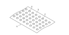
- the PTP sheet 1 As shown in FIGS. 1 and 2, the PTP sheet 1 includes a container film 3 having a plurality of pocket portions 2 and a cover film 4 attached to the container film 3 so as to close the pocket portions 2. is doing.
- the container film 3 is made of, for example, a transparent or translucent thermoplastic resin material that is relatively hard and has a predetermined rigidity, such as PP (polypropylene) or PVC (polyvinyl chloride).
- the cover film 4 is made of an opaque material (for example, an aluminum foil or the like) having a sealant made of, for example, a polyester resin applied on the surface.
- the PTP sheet 1 is formed in a substantially rectangular shape in plan view, and two rows of pockets formed of five pocket portions 2 arranged along the longitudinal direction of the sheet are formed in the lateral direction of the sheet. That is, a total of 10 pocket portions 2 are formed.
- Each pocket 2 stores one tablet 5 as a content.
- the tablet 5 has a circular disk shape in plan view, and includes a side surface 5A, and a flat surface 5B and a back surface 5C sandwiching the side surface 5A.
- the PTP sheet 1 is manufactured into a sheet shape by punching a strip-shaped PTP film 6 (see FIG. 3) formed from the strip-shaped container film 3 and the cover film 4.
- the raw material of the strip-shaped container film 3 is wound into a roll.
- the drawing end side of the container film 3 wound in a roll shape is guided by a guide roll 13.
- the container film 3 is hooked on the intermittent feed roll 14 on the downstream side of the guide roll 13.
- the intermittent feed roll 14 is connected to a motor that rotates intermittently and transports the container film 3 intermittently.
- a heating device 15 and a pocket portion forming device 16 are arranged in this order along the conveyance path of the container film 3. Then, in a state where the container film 3 is heated by the heating device 15 and the container film 3 becomes relatively flexible, the pocket portion forming device 16 forms a plurality of pocket portions 2 at predetermined positions of the container film 3. The pocket portion 2 is formed at an interval between the transport operations of the container film 3 by the intermittent feed roll 14.
- the container film 3 fed from the intermittent feed roll 14 is hung in the order of a tension roll 18, a guide roll 19, and a film receiving roll 20. Since the film receiving roll 20 is connected to a motor that rotates at a constant speed, the container film 3 is transported continuously and at a constant speed.
- the tension roll 18 is in a state where the container film 3 is pulled toward the side where the container film 3 is tensioned by an elastic force, and prevents the container film 3 from slackening due to the difference in the transport operation between the intermittent feed roll 14 and the film receiving roll 20.
- the container film 3 is always kept in a tension state. Thereby, the container film 3 is continuously conveyed between the tension roll 18 and the film receiving roll 20 without stopping.
- a filling device 21 as a filling means and a pre-seal inspection device 22 are arranged in this order along the conveyance path of the container film 3.
- the filling device 21 has a function of automatically filling the tablet 5 with the tablet 2.
- the configuration of the filling device 21 will be described in detail later.
- the pre-seal inspection device 22 mainly inspects for tablet defects such as whether or not the tablets 5 are reliably filled in the pockets 2, whether or not the tablets 5 are abnormal, and whether or not foreign matter is mixed into the pockets 2. Is for.
- the raw material of the cover film 4 formed in a belt shape is wound in a roll shape on the most upstream side.
- the drawn end of the cover film 4 wound in a roll shape is guided toward the heating roll 26 by the guide roll 25.
- the heating roll 26 can be pressed against the film receiving roll 20, and the container film 3 and the cover film 4 are fed between the rolls 20 and 26. And when the container film 3 and the cover film 4 pass between both rolls 20 and 26 in a heating-pressing state, the cover film 4 is stuck to the container film 3, and the pocket part 2 is block
- the film receiving roll 20 and the heating roll 26 constitute a sealing means.
- the PTP film 6 sent out from the film receiving roll 20 is hung in the order of the tension roll 27 and the intermittent feed roll 28. Since the intermittent feed roll 28 is connected to a motor that rotates intermittently, the PTP film 6 is intermittently conveyed.
- the tension roll 27 is in a state in which the PTP film 6 is pulled toward the side to be tensioned by an elastic force, and prevents the PTP film 6 from slacking due to the difference in transport operation between the film receiving roll 20 and the intermittent feed roll 28.
- the PTP film 6 is always kept in tension.
- a post-seal inspection device 29 is disposed between the film receiving roll 20 and the tension roll 27 along the transport path of the PTP film 6.
- the post-seal inspection device 29 mainly inspects the cover film 4 for damage such as cracks and breaks.
- the PTP film 6 sent out from the intermittent feed roll 28 is hooked in the order of the tension roll 31 and the intermittent feed roll 32. Since the intermittent feed roll 32 is connected to an intermittently rotating motor, the PTP film 6 is intermittently conveyed.
- the tension roll 31 is in a state in which the PTP film 6 is pulled to the side where the PTP film 6 is tensioned by an elastic force, and prevents the PTP film 6 from loosening between the intermittent feed rolls 28 and 32.
- a slit forming device 33 and a marking device 34 are disposed along the transport path of the PTP film 6.
- the slit forming device 33 has a function of forming a slit for separation at a predetermined position of the PTP film 6.
- the marking device 34 has a function of marking a predetermined position (for example, a tag portion) of the PTP film 6.
- the PTP film 6 fed from the intermittent feed roll 32 is hooked in the order of the tension roll 35 and the continuous feed roll 36 on the downstream side.
- a sheet punching device 37 as a punching unit is disposed along the transport path of the PTP film 6.
- the sheet punching device 37 has a function of punching the outer edge of the planned sheet portion 7 (see FIG. 15), which is a part that finally becomes the PTP sheet 1 in the PTP film 6.
- the PTP sheet 1 punched by the sheet punching device 37 is transported by the take-out conveyor 38 and temporarily stored in the finished product hopper 39.
- the PTP sheet 1 (defective sheet) determined to be defective by the inspection devices 22 and 29 is separately discharged by a defective sheet discharge mechanism (not shown).
- a cutting device 41 is disposed downstream of the continuous feed roll 36. Then, the unnecessary film portion 42 constituting the remaining material portion (scrap portion) remaining in a strip shape after being punched by the sheet punching device 37 is guided to the tension roll 35 and the continuous feed roll 36 and then guided to the cutting device 41. It is burned.
- the continuous feed roll 36 is in pressure contact with a driven roll, and performs a conveying operation while sandwiching the unnecessary film portion 42.
- the cutting device 41 has a function of cutting the unnecessary film portion 42 into a predetermined size and scrapping. The scrap is stored in the scrap hopper 43 and then disposed of separately.
- Each of the rolls 14, 19, 20, 28, 31, 32 and the like has a positional relationship in which the roll surface and the pocket portion 2 face each other. Since the recessed part which accommodates is formed, the pocket part 2 is not crushed fundamentally. Further, the feeding operation is performed while the pocket portion 2 is accommodated in the recesses such as the rolls 14, so that the intermittent feeding operation and the continuous feeding operation are performed reliably.
- the filling device 21 includes a main body device 51, an appearance inspection device 71, and a control device 81.
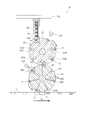
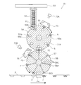
- the main body device 51 includes a storage portion 52, a supply chute 53, an upstream drum 54, and a downstream drum 57, which are provided in this order from the top to the bottom.
- the storage unit 52 has a function of storing the tablets 5, and the tablets 5 are sequentially supplied from here to the supply chute 53.
- the supply chute 53 has a cylindrical shape, and a plurality (five in this embodiment) of the supply chutes 53 are arranged along the axial direction of the drums 55 and 58 (the depth direction in FIG. 5).
- Each supply chute 53 has a lower opening located immediately above the upstream drum 54, and a shutter 53A capable of opening and closing the lower opening is provided in the vicinity of the lower opening.
- the opening / closing operation of the shutter 53A is controlled by the control device 81.
- the shutter 53A corresponds to the supply switching unit.
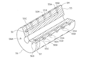
- the upstream drum 54 includes a cylindrical upstream rotary drum 55 and a disk-shaped upstream fixed valve 56 arranged coaxially therewith.
- the upstream rotating drum 55 is continuously rotated by a driving means (not shown) according to the speed of the downstream rotating drum 58 described later.
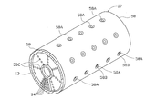
- the upstream rotary drum 55 includes a plurality of upstream suction portions 55A and a plurality of upstream vent holes 55C.
- the upstream suction portion 55A includes a hollow portion provided on the outer peripheral surface of the upstream rotary drum 55, and an upstream suction hole 55B that opens at the center of the hollow portion, and the upstream suction hole.
- the upstream suction portions 55A are provided in the same number as the number of pocket portions 2 along the width direction of the container film 3 along the axial direction of the upstream rotating drum 55 (five in this embodiment). A plurality (seven in this embodiment) are provided at equal intervals along the circumferential direction of the upstream rotating drum 55.
- the upstream suction portion 55A may be individually indicated by using symbols Y1 to Y35 (see FIG. 8).
- the upstream suction portion 55A sequentially moves with respect to the chute corresponding position P1 and the supply position P2 as the upstream rotary drum 55 rotates (see FIG. 5).
- the chute corresponding position P1 is a position corresponding to the drop position of the tablet 5 from the supply chute 53, and the tablet 5 is supplied from the supply chute 53 to the upstream suction portion 55A arranged at this position.
- the supply position P2 is a position positioned vertically below the axis of the upstream rotary drum 55, and at this position, the tablet 5 is delivered from the upstream suction portion 55A to the downstream suction portion 58A described later.
- the upstream vent hole 55C is provided in the upstream rotary drum 55, extends in the axial direction of the upstream rotary drum 55, and opens at one end surface of the upstream rotary drum 55 (the surface on the upstream fixed valve 56 side). is doing.
- a plurality of upstream side vent holes 55C are provided at equal intervals along the rotation direction of the upstream side rotary drum 55, and the upstream side vent holes 55C are upstream of one upstream side vent hole 55C.
- a plurality of upstream suction holes 55B arranged in the axial direction of the side rotating drum 55 are in communication with each other.
- the upstream rotary drum 55 is provided with an encoder (not shown), and a signal related to the rotation angle of the upstream rotary drum 55 is output from the encoder to the control device 81 and the appearance inspection device 71 at regular intervals. Yes.
- the upstream side fixed valve 56 is provided so as to cover one end face of the upstream side rotating drum 55, and unlike the upstream side rotating drum 55, the upstream side fixed valve 56 is immovable.
- the upstream fixed valve 56 includes an upstream negative pressure space S1 and an air release space S2 that are open to one end surface of the upstream rotating drum 55. Both the space portions S1 and S2 are curved around the axis of the upstream fixed valve 56, respectively.
- the upstream negative pressure space S1 corresponds to the upstream suction hole 55B of the upstream suction portion 55A when the upstream suction portion 55A is disposed in a region from the chute corresponding position P1 to the front of the supply position P2. This is a space communicating with the upstream side vent hole 55C.
- the upstream negative pressure space S1 is constantly supplied with negative pressure from a predetermined vacuum pump 61 via a through hole 56A formed in the upstream fixed valve 56 and a predetermined vent pipe 62 communicating with the through hole 56A. It is in the state (the state evacuated) (refer FIG. 12).
- the upstream open space portion S2 is connected to the upstream suction hole 55B corresponding to the upstream suction hole 55B of the upstream suction portion 55A. It is a space communicating with the pore 55C.
- the atmosphere opening space S2 is always open to the atmosphere via a through hole 56B formed in the upstream side fixed valve 56 (see FIG. 12).
- the upstream suction portion 55A arranged at the chute corresponding position P1 is in a suckable state, and holds the tablet 5 that has fallen from the supply chute 53 by suction.
- the upstream suction portion 55A that sucks and holds the tablet 5 reaches the supply position P2 as the upstream rotation drum 55 rotates, the suction holding of the tablet 5 by the upstream suction portion 55A is released, and the downstream suction is performed.
- the tablet 5 is delivered to the part 58A.
- the upstream drum 54 and the supply chute 53 correspond to supply means.
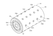
- the downstream drum 57 includes a cylindrical downstream rotary drum 58 and a disk-shaped downstream fixed valve 59 arranged coaxially therewith.
- the downstream rotary drum 58 corresponds to the rotary drum.
- the downstream rotary drum 58 is continuously rotated by a driving means (not shown) according to the speed of the container film 3 being conveyed.
- the downstream rotary drum 58 has the same diameter as the upstream rotary drum 55 and rotates at the same rotational speed as the upstream rotary drum 55.
- the downstream rotary drum 58 includes a plurality of downstream suction portions 58A and a plurality of downstream vent holes 58C.
- the downstream suction portion 58A includes a hollow portion provided on the outer peripheral surface of the downstream rotary drum 58, and a downstream suction hole 58B that opens at the center of the hollow portion, and the downstream suction hole.
- the tablet 5 delivered from the upstream suction portion 55A is sucked and held.
- the same number of downstream suction portions 58 ⁇ / b> A as the upstream suction portions 55 ⁇ / b> A are provided, and the arrangement positions of the downstream suction portions 58 ⁇ / b> A on the outer peripheral surface of the downstream rotary drum 58 are on the outer peripheral surface of the upstream rotary drum 55. It is the same as the arrangement position of the upstream suction portion 55A.
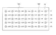
- the downstream-side adsorbing portion 58A may be individually indicated by reference numerals X1 to X35 (see FIG. 11).
- the tablets 5 are delivered between the two adsorbing portions 55A and 58A having the same numerical values in the symbols X1 to X35 and Y1 to Y35.
- the tablet 5 is delivered from the upstream suction portion 55A indicated by the reference symbol Y1 to the downstream suction portion 58A indicated by the reference symbol X1.
- downstream suction unit 58A sequentially moves with respect to the supply position P2, the imaging position P3, and the filling position P4 as the downstream rotary drum 58 rotates (see FIG. 5).
- the imaging position P3 is a position corresponding to a downstream camera 73B, which will be described later.
- the downstream suction unit 58A is disposed at this position, the tablet 5 sucked by the downstream suction unit 58A by the downstream camera 73B. Imaging is performed.
- the filling position P4 is a position corresponding to a position vertically below the axis of the downstream rotary drum 58, and the tablet 5 that has been sucked and held at the downstream suction portion 58A at this position is filled into the pocket portion 2.
- two rows of the downstream suction portions 58A arranged along the rotation direction of the downstream rotary drum 58 are used.
- the two rows downstream of the suction portions 58A is changed from the chute corresponding position P1 to the supply position P2.
- the downstream vent 58C is provided in the downstream rotary drum 58, extends in the axial direction of the downstream rotary drum 58, and opens at one end surface of the downstream rotary drum 58 (the surface on the downstream fixed valve 59 side). is doing.
- a plurality of downstream side vent holes 58C are provided side by side along the radial direction of the downstream side rotary drum 58 (five in this embodiment), and a row of downstream side vent holes 58C aligned in the radial direction is provided.
- a plurality (seven in this embodiment) are provided at equal intervals along the rotation direction of the downstream rotary drum 58.
- Each downstream side vent hole 58C is in communication with one downstream suction hole 58B, and the shaft of the downstream rotary drum 58 is connected to one row of downstream side vent holes 58C arranged in the radial direction.
- One row of downstream suction holes 58B aligned in the direction is in a corresponding state.
- the downstream rotary drum 58 is provided with an encoder (not shown), and a signal related to the rotation angle of the downstream rotary drum 58 is output from the encoder to the control device 81 and the appearance inspection device 71 at regular intervals. Yes.
- the downstream side fixed valve 59 is provided so as to cover one end surface of the downstream side rotating drum 58, and unlike the downstream side rotating drum 58, the downstream side fixed valve 59 is immovable.
- the downstream fixed valve 59 includes a downstream negative pressure space portion S3 and a switching space portion S4 that are open to one end surface side of the downstream rotation drum 58. Both the space portions S3 and S4 are curved with the axis of the downstream fixed valve 59 as the center.
- the downstream negative pressure space portion S3 is located downstream when the downstream suction portion 58A is disposed in a range including the supply position P2 from a position slightly past the filling position P4 to a position before the filling position P4. This is a space communicating with the downstream vent hole 58C corresponding to the downstream suction hole 58B of the side suction portion 58A.
- the downstream negative pressure space S3 is always supplied with negative pressure from the vacuum pump 61 via a through hole 59A formed in the downstream fixed valve 59 and a predetermined vent pipe 63 communicating with the through hole 59A. It is in a state (a state evacuated) (see FIG. 12). Further, the downstream negative pressure space S3 has a relatively large width along the radial direction of the downstream fixed valve 59. Therefore, the downstream negative pressure space S3 can communicate with the downstream vent holes 58C arranged in a line along the radial direction at a time.
- the switching space portion S4 is arranged in the downstream suction portion. This is a space communicating with the downstream side vent hole 58C corresponding to the downstream side suction hole 58B of 58A.
- a plurality of switching spaces S4 are provided at equal intervals along the radial direction of the downstream fixed valve 59, and each has a circular arc shape. Each switching space portion S4 is individually communicated with one of the downstream air holes arranged in a line along the radial direction as the downstream rotating drum 58 rotates.
- the length of the switching space S4 along the circumferential direction of the downstream fixed valve 59 is shorter than the interval between the downstream vent holes 58C along the rotation direction of the downstream rotating drum 58, and one switching is performed.
- Two or more downstream vent holes 58C are configured not to communicate with the space S4 at the same time.
- Each switching space S4 is connected to the vacuum pump 61 via a through hole 59B formed in the downstream fixed valve 59 and a predetermined vent pipe 64 communicating with the through hole 59B.
- the vent pipe 64 is provided with an electromagnetic switching valve 65 as an adsorption state switching means.
- the electromagnetic switching valve 65 switches between a state in which negative pressure is supplied from the vacuum pump 61 to the switching space portion S4 and a state in which the switching space portion S4 is open to the atmosphere. .
- the electromagnetic switching valve 65 is electrically connected to the control device 81, and the operation of the electromagnetic switching valve 65 is controlled by the control device 81.
- the downstream suction portion 58A disposed at the supply position P2 is in a suckable state, and sucks and holds the tablet 5 delivered from the upstream suction portion 55A. .
- the surface to be adsorbed in the tablet 5 is reversed.
- the downstream suction portion 58A that sucks and holds the tablet 5 reaches the filling position P4 as the downstream rotary drum 58 rotates, the corresponding switching space portion S4 is opened to the atmosphere.
- the adsorption of the tablet 5 by the downstream-side adsorption portion 58A is released, and the tablet 5 is filled into the pocket portion 2.
- the adsorption of the tablet 5 by the downstream side adsorption portion 58A is maintained, and the tablet 5 is not filled into the pocket portion 2.
- the downstream suction portion 58A that maintains the suction of the tablet 5 returns to the supply position P2 in that state.
- the appearance inspection apparatus 71 includes an upstream illumination device 72A, a downstream illumination device 72B, an upstream camera 73A as second imaging means, a downstream camera 73B as first imaging means, and pass / fail judgment means. As a pass / fail judgment device 74.
- both cameras 73A and 73B correspond to the imaging means.
- the upstream illumination device 72A corresponds to the upstream drum 54, and has a predetermined light (for example, near infrared light or visible light) with respect to the tablet 5 disposed at a predetermined position between the chute corresponding position P1 and the supply position P2. ).
- a predetermined light for example, near infrared light or visible light
- the downstream illumination device 72B corresponds to the downstream drum 57, and irradiates predetermined light (for example, near infrared light or visible light) to the downstream suction unit 58A disposed at the imaging position P3. Illuminate the tablet 5 adsorbed on the downstream adsorption portion 58A.
- predetermined light for example, near infrared light or visible light
- the upstream camera 73A and the downstream camera 73B take an image of the tablet 5 irradiated with light by the illumination devices 72A and 72B.
- a CCD camera having a convex lens and having sensitivity in the wavelength region of light emitted from the illumination devices 72A and 72B is employed as the cameras 73A and 73B.
- a CMOS camera may be employed.
- a plurality of cameras 73A and 73B are provided corresponding to the number of suction portions 55A and 58A along the axial direction of the rotating drums 55 and 58, and one camera 5 is imaged by each of the cameras 73A and 73B. It is comprised so that. Note that a relatively small number of cameras 73A and 73B (for example, one each) may be provided, and a predetermined mirror may be used so that the plurality of tablets 5 are imaged at a time by the cameras 73A and 73B.
- the upstream camera 73 ⁇ / b> A corresponds to the upstream drum 54 and images the tablet 5 conveyed by the upstream rotating drum 55.
- the upstream camera 73A is configured such that the distance from the convex lens to its focal point (focal distance) is larger than the distance from the convex lens to the tablet 5 to be imaged. Thereby, the upstream camera 73A can image the side surface 5A as well as the surface (one of the front surface 5B and the back surface 5C) opposite to the surface to be adsorbed in the tablet 5.
- the downstream camera 73B corresponds to the downstream drum 57 and images the tablet 5 conveyed to the imaging position P3 by the downstream rotating drum 58.
- the downstream camera 73B is configured such that the focal distance is larger than the distance from the convex lens to the tablet 5 to be imaged, similarly to the upstream camera 73A. Therefore, the downstream side camera 73B can image the side surface 5A as well as the surface (the other of the front surface 5B and the back surface 5C) opposite to the surface to be adsorbed in the tablet 5. That is, in this embodiment, the whole area of the outer surface of the tablet 5 can be imaged by both cameras 73A and 73B.
- the image data (luminance image data or color image data) captured by the cameras 73A and 73B is converted into digital signals inside the cameras 73A and 73B, and then input to the pass / fail judgment device 74 in the form of digital signals.
- the pass / fail judgment device 74 is configured as a so-called computer system including a CPU as a calculation means, a ROM for storing various programs, a RAM for temporarily storing various data such as calculation data and input / output data, and the like. Various processes such as image processing can be executed.
- the pass / fail determination device 74 includes an image memory 75A, an inspection result storage device 75B, a determination memory 75C, a data memory 75D, a camera timing control device 76, and a CPU and an input / output interface 77.
- image processing such as processing, defect determination processing (inspection processing), and the like can be performed.
- the image memory 75A stores two-dimensional image data (image data) of captured images output from the cameras 73A and 73B.
- An inspection is executed based on the image data stored in the image memory 75A.
- the image data may be processed.
- processing such as masking processing or shading correction.
- the shading correction is for correcting variations in light brightness caused by a difference in position because there is a technical limit to uniformly illuminating the entire imaging range of the tablet 5 with light from the illumination devices 72A and 72B. is there.
- binarized image data obtained by performing binarization processing on image data at the time of inspection, masking image data subjected to masking processing, and the like are also stored in the image memory 75A.
- the inspection result storage device 75B stores data such as coordinates relating to image data, data of pass / fail judgment results for the inspection object, statistical data obtained by probabilistically processing the data, and the like.
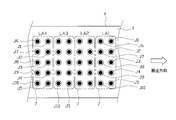
- information indicating the pass / fail judgment result for each tablet 5 indicated by predetermined tablet numbers J1 to J10 is stored in the scheduled sheet portion 7 to which these tablets 5 are to be supplied. It is stored together with serial numbers LA1, LA2, LA3, LA4... (See FIG. 15) for identification (see FIG. 14. In FIG. 14, non-defective products are indicated by “ ⁇ ”, and defects are indicated by “x”. Show).
- the quality of the tablet 5 is determined based on a plurality of inspection items. If all the inspection items are determined to be good, the tablet 5 is determined to be non-defective, and at least one inspection item is determined to be defective. If it is determined that the tablet 5 is defective. As inspection items, for example, an item related to whether or not the tablet 5 is cracked (item related to so-called “tablet cracking”), an item related to whether or not the tablet 5 is chipped (so-called “tablet missing”).
- the determination memory 75C stores determination values (threshold values, etc.) used for inspection.
- the determination value is set for each inspection item.
- the determination values used for the inspection include, for example, the dimensions of the tablet 5 and the like, the shapes and dimensions of various window frames for defining various inspection regions, the threshold value for binarization processing, the determination value for area determination, the color identification inspection
- the color reference value related to is included.
- the data memory 75D is composed of, for example, a hard disk device, and stores the date and time of defect determination, the inspection conditions used for the inspection, and the like in the data memory 75D.
- the camera timing control device 76 controls the imaging timing of both cameras 73A and 73B.
- the imaging timing is controlled based on signals from the encoders of both rotary drums 55 and 58, and imaging is performed by the cameras 73A and 73B every time the rotary drums 55 and 58 rotate by a predetermined amount.
- the CPU and input / output interface 77 are responsible for various controls in the appearance inspection apparatus 71. For example, various processing programs are executed, and the quality of the tablet 5 is determined based on the obtained image data.
- the CPU and input / output interface 77 has a function of transmitting and receiving various signals to and from the control device 81. Further, the CPU and the input / output interface 77 increment the serial number of the scheduled sheet portion 7 one by one every time the downstream-side rotary drum 58 rotates by a certain amount, and is indicated by the serial number and the serial number. The correspondence relationship with the tablet 5 scheduled to be supplied to the scheduled sheet portion 7 can be grasped.
- the information indicating the pass / fail judgment result for each tablet 5 indicated by the tablet numbers J1 to J10 and the serial number for specifying the scheduled sheet portion 7 to which these tablets 5 are to be supplied are associated with each other.
- the inspection result storage device 75B it is stored in the inspection result storage device 75B.
- the pass / fail determination result of the tablet 5 is derived without any delay after the image data is acquired by the cameras 73A and 73B, and information regarding the derived pass / fail determination result is immediately transmitted to the control device 81. Configured to be sent to.
- the pass / fail judgment result of each tablet 5 scheduled to be supplied to one sheet planned portion 7 is the upstream side that delivers the tablet 5 to the downstream suction portion 55A that is sucking each tablet 5.
- the suction portion 58A is derived before reaching the chute corresponding position P1.
- the control device 81 is configured as a so-called computer system, similar to the quality determination device 74.
- the control device 81 corresponds to an adsorption state control unit and a supply control unit.
- the control device 81 is electrically connected to the main body device 51 and the appearance inspection device 71, can receive information on the rotation amount of the rotary drums 55 and 58 from the main body device 51, and determines whether the appearance inspection device 71 is good or bad. Information about the result is configured to be received.
- the control device 81 can grasp the positions of the suction portions 55A and 58A based on information from the rotary drums 55 and 58. Further, the control device 81 can grasp the quality of each tablet 5 for each scheduled sheet portion 7 based on information from the appearance inspection device 71.
- control device 81 provides other non-defective products scheduled to be supplied to the scheduled sheet portion 7 to the scheduled sheet portion 7 to which the tablet 5 determined to be defective is scheduled to be supplied based on the quality determination result of the tablet 5.
- the main body device 51 is controlled so as not to supply the tablet 5.
- control device 81 first performs a process (operation schedule setting process) for setting the switching schedule of the electromagnetic switching valve 65 and the supply schedule of the supply chute 53 based on the quality determination result of the tablet 5.
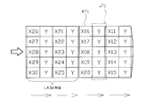
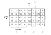
- the set switching schedule related to the electromagnetic switching valve 65 is additionally stored in the adsorption switching schedule table KT1 (see FIGS. 16 and 18) of the RAM in the control device 81.
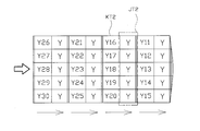
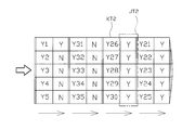
- the set supply schedule of the supply chute 53 is additionally stored in the RAM supply switching schedule table KT2 (see FIGS. 17 and 19).
- “Y” indicates that the electromagnetic switching valve 65 is operated so that the switching space portion S4 is opened to the atmosphere, and electromagnetic switching is performed so that a negative pressure is supplied to the switching space portion S4.
- the operation of the valve 65 is indicated by “N”.
- “Y” indicates that the supply chute 53 is opened so that the tablet 5 is supplied to the upstream suction portion 55 ⁇ / b> A, and the tablet 5 is not supplied to the upstream suction portion 55 ⁇ / b> A.
- “N” indicates that the supply chute 53 is closed.
- the symbols X1 to X35 and Y1 to Y35 of the suction portions 55A and 58A corresponding to the electromagnetic switching valve 65 to be operated are also shown for easy explanation.
- the control device 81 shifts the data of the suction switching scheduled table KT1 at every predetermined timing (for example, every time the downstream suction portion 58A reaches the imaging position P3).
- Data relating to the switching schedule of the electromagnetic switching valve 65 corresponding to the downstream suction portions 58A arranged in a line in the axial direction is sequentially shifted to a predetermined implementation table JT1 (see FIGS. 16 and 18).
- the control device 81 operates the electromagnetic switching valve 65 based on the data of the implementation table JT1 at the timing immediately before each downstream suction portion 58A corresponding to the data of the implementation table JT1 reaches the filling position P4.
- the execution timing of the operation control of the electromagnetic switching valve 65 is determined based on the signal from the encoder of the downstream rotary drum 58.
- control device 81 shifts the data of the supply switching scheduled table KT2 at every predetermined timing (for example, every time the upstream suction portion 55A reaches the chute corresponding position P1), so that the upstream rotary drum 55 Data relating to the supply schedule of the supply chute 53 corresponding to the upstream suction portions 55A arranged in a line in the axial direction is sequentially shifted to a predetermined implementation table JT2 (see FIGS. 17 and 19). Then, the control device 81 operates the supply chute 53 based on the data of the implementation table JT2 at a timing immediately before each upstream suction portion 55A corresponding to the data of the implementation table JT2 reaches the chute corresponding position P1. To control. The execution timing of the operation control of the supply chute 53 is determined based on the signal from the encoder of the upstream rotary drum 55.
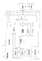
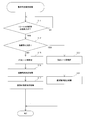
- step S11 information related to the pass / fail judgment result of the tablet 5 (tablet 5 for one sheet) scheduled to be supplied to one scheduled sheet section 7 is obtained from the control device. A determination is made as to whether or not the input has been made to 81. In the present embodiment, it is determined whether or not information related to the pass / fail determination result of 10 tablets 5 corresponding to one scheduled sheet portion 7 has been input. And the process of step S11 is repeated until the information regarding the quality determination result of the tablet 5 for 1 sheet is input, When the information regarding the quality determination result of the tablet 5 for 1 sheet is input (step S11: YES), The process proceeds to step S12.
- step S12 it is determined whether or not all the tablets 5 for one sheet are non-defective products. When all the tablets 5 are non-defective products (step S12: YES), the process proceeds to step S13.
- step S13 the scheduled sheet portion 7 to which the tablet 5 to be determined is to be supplied is specified as a non-defective sheet portion, and the process proceeds to step S14.
- step S14 a normal operation setting process is performed, and the process returns to the step S11.
- the tablet 5 is supplied to the non-defective sheet portion, and a new tablet 5 is supplied to the downstream suction portion 58A after the tablet 5 is supplied to the non-defective sheet portion.
- 51 operation schedules are set.
- the switching schedule of the electromagnetic switching valve 65 is set so that the downstream suction holes 58B of the respective downstream suction portions 58A corresponding to the non-defective sheet portions are opened to the atmosphere.
- the set switching schedule is added to the operation schedule table KT1 and stored. For example, when the scheduled sheet portion 7 indicated by the serial number LA3 is a non-defective sheet portion, the downstream side adsorption portion 58A indicated by reference numerals X21 to X30 corresponding to the tablet 5 scheduled to be supplied to the non-defective sheet portion.
- the switching schedule of the corresponding electromagnetic switching valve 65 is set so that the downstream suction hole 58B is opened to the atmosphere (see FIG. 16). After that, the set switching schedule is added and stored in the suction switching schedule table KT1.
- the supply chute 53 is scheduled to be supplied so that a new tablet 5 is supplied to each downstream suction portion 58A corresponding to each tablet 5 to be supplied to the non-defective sheet portion.
- the set supply schedule is stored in the supply switching schedule table KT2. For example, when the scheduled sheet portion 7 indicated by the serial number LA3 is a non-defective sheet portion, the upstream suction portion 55A indicated by reference symbols Y21 to Y30 corresponding to the downstream suction portion 58A indicated by reference symbols X21 to X30 is entered. The supply schedule of the supply chute 53 is set so that the tablet 5 is supplied at the supply position P2 (see FIG. 17). After that, the set supply schedule is added and stored in the supply switching schedule table KT2.
- step S12 when at least one of the tablets 5 for one sheet is defective (step S12: NO), the process proceeds to step S15, and the scheduled sheet portion 7 where the defective tablet 5 is supplied is designated as a defective sheet. Specify as a part. For example, when at least one of the tablets 5 scheduled to be supplied to the scheduled sheet portion 7 indicated by the serial number LA4 is determined to be defective, the planned sheet portion 7 is specified as a defective sheet portion.
- step S16 following step S15, an adsorption maintenance determination process is performed.
- the negative pressure is supplied to the one corresponding to the non-defective tablet 5 among the downstream suction holes 58B of each downstream suction portion 58A corresponding to the defective sheet portion
- the switching schedule of the electromagnetic switching valve 65 is set so that the one corresponding to the defective tablet 5 is opened to the atmosphere. After that, the set switching schedule is added and stored in the suction switching schedule table KT1. For example, assume that the scheduled sheet portion 7 indicated by the serial number LA4 is a defective sheet portion (see FIG. 14).
- the downstream suction unit 58A indicated by reference numerals X2 to X5 and X31 to X35 corresponding to the non-defective tablet 5 among the tablets 5 scheduled to be supplied to the defective sheet portion corresponds.
- the switching schedule of the electromagnetic switching valve 65 is set so that negative pressure is supplied to the downstream suction hole 58B (see FIG. 18).
- the electromagnetic switching valve 65 is scheduled to be switched so that the corresponding downstream suction hole 58B is opened to the atmosphere. Is set (see FIG. 18). After that, the set switching schedule is added to and stored in the suction switching schedule table KT1.
- step S17 a tablet non-supply determination process is performed, and the process returns to step S11.
- the new tablet 5 is prevented from being supplied to the downstream suction portion 58A corresponding to the non-defective tablet 5, while the defective
- the supply schedule of the supply chute 53 is set so that the new tablet 5 is supplied to the downstream side adsorption portion 58A corresponding to the tablet 5 of the first tablet 5.
- the set supply schedule is added to the supply switching schedule table KT2. For example, assume that the scheduled sheet portion 7 indicated by the serial number LA4 is a defective sheet portion (see FIG. 14).
- the supply chute is provided so that the tablet 5 is not supplied to the upstream suction portion 55A indicated by reference numerals Y2 to Y5 and Y31 to Y35 corresponding to the downstream suction portion 58A indicated by reference numerals X2 to X5 and X31 to 35.
- the supply schedule of 53 is set (see FIG. 19).
- the supply schedule of the supply chute 53 is set so that the tablet 5 is supplied to the upstream suction portion 55A indicated by the reference symbol Y1 corresponding to the downstream suction portion 58A indicated by the reference symbol X1 (see FIG. 19). .
- the set supply schedule is added to the supply switching schedule table KT2 and stored.
- the sheet scheduled portion 7 (defects) to which the tablets 5 related to the defect determination are to be supplied at the filling position P4.
- the non-defective tablet 5 is not supplied to the sheet portion) and is maintained in the state of being adsorbed by the downstream-side adsorption portion 58A. Therefore, the non-defective tablet 5 does not exist in the defective sheet after punching. Thereby, there is no need to take out the non-defective tablet 5 from the defective sheet in order to reuse the non-defective tablet 5, and the non-defective tablet 5 is not wasted even if the defective sheet is discarded as it is. .
- downstream suction portion 58A that sucks and holds the non-defective tablet 5 moves again to the supply position P2 and the filling position P4 with the rotation of the downstream rotary drum 58, but with respect to the downstream suction portion 58A. Without the new tablet 5 being supplied at the supply position P2, the downstream suction portion 58A moves to the filling position P4 while holding the non-defective tablet 5 by suction.
- the non-defective tablet 5 is filled into the pocket portion 2 at the filling position P4. . That is, the non-defective tablet 5 relating to the defective sheet portion is sucked and held as it is at the filling position P4 without being filled into the pocket portion 2 or collected from the pocket portion 2, and used at the next and subsequent fillings. .
- the non-defective tablet 5 can be used without wasting it while preventing the breakage of the tablet 5 more reliably and without taking time and effort.
- the device since it is not necessary to provide a separate device for collecting the tablets 5, the device can be simplified and various costs can be reduced.
- the non-defective tablet 5 is not supplied to the defective sheet portion, and only the defective tablet 5 is supplied. Accordingly, as shown in FIG. 21, in the PTP sheet 1 related to the finally obtained defective sheet portion, only the defective tablet 5 is filled in the pocket portion 2. Thereby, the abnormalities which have occurred can be easily identified by looking at the filled tablets 5. As a result, it is possible to easily identify an inspection item or the like in which a defect has occurred, and to perform appropriate measures at an early stage.
- the defective tablet 5 is supplied to the defective sheet portion, an apparatus for separately discharging the defective tablet 5 becomes unnecessary. Therefore, simplification of the apparatus and reduction of various costs can be achieved more effectively.
- the surface to be adsorbed of the tablet 5 by the adsorbing portions 55A and 58A is reversed so that the side surfaces of the tablet 5 are obtained by the cameras 73A and 73B.
- 5A, the front surface 5B, and the back surface 5C can be imaged. Therefore, the quality determination can be performed on the entire outer surface of the tablet 5, and the quality determination can be performed with higher accuracy.
- pass / fail judgment is performed based on the imaging data including the data related to the side surface 5A. Therefore, it is not necessary to perform the pass / fail determination of the side surface 5A separately from the front surface 5B and the back surface 5C. As a result, the time required for pass / fail judgment can be shortened, and the inspection efficiency can be improved.
- the supply and non-supply of the tablet 5 to the downstream suction portion 58A disposed at the supply position P2 can be switched by switching the supply and non-supply of the tablet 5 from the supply chute 53 to the upstream suction portion 55A.
- suction part 58A can be switched easily, improving the precision of quality determination by using the two rotating drums 55 and 58.
- the supply unit is configured by the upstream drum 54 and the supply chute 53, but the supply unit may be configured by only the supply chute 53 as shown in FIG. . That is, the tablet 5 may be directly supplied to the downstream rotating drum 58 without passing through the upstream drum 54.
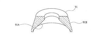
- the side surface 5A of the tablet 5 is imaged by the cameras 73A and 73B by using a convex lens and adjusting the focal length, but as shown in FIGS.
- the side surface 5 ⁇ / b> A may be imaged using the prism 91.
- the prism 91 includes, for example, a truncated cone-shaped inner peripheral surface 91A and an outer peripheral surface 91B, and is disposed between the cameras 73A and 73B and the tablet 5 to be imaged.
- the reflected light from the side surface 5A that has passed through the inner peripheral surface 91A is reflected by the outer peripheral surface 91B, and the reflected light is reflected by the inner peripheral surface 91A and enters the cameras 73A and 73B. Is imaged.
- the distortion of the side surface 5A in the obtained image data can be further suppressed, and the accuracy of the quality determination can be further improved.
- the tablet 5 determined to be defective is configured to be supplied to the defective sheet portion.
- the tablet 5 determined to be defective is transferred to a predetermined defective product discharge unit (for example, a defective tablet). It is good also as discharging to the container for accommodating 5 etc.).
- a predetermined defective product discharge unit for example, a defective tablet. It is good also as discharging to the container for accommodating 5 etc.).
- the tablet 5 may be removed by bringing a predetermined nail-shaped member into contact with the tablet 5, or the downstream suction hole 58B may be removed. You may remove the tablet 5 by supplying air.
- the content is the tablet 5
- the type, shape, and the like of the content are not particularly limited.
- the content such as a capsule, an electronic component, food, etc.
- the product may be different from the tablet 5.
- the container film 3 is formed of a transparent or translucent thermoplastic resin material such as PP or PVC, and the cover film 4 is formed using an aluminum foil or the like as a base material.
- PP transparent or translucent thermoplastic resin material
- the cover film 4 is formed using an aluminum foil or the like as a base material. , 4 are not limited to these, and other materials may be employed.
- the configuration of the appearance inspection apparatus 71 is not limited to the above embodiment.
- the inspection items in the above embodiment are merely examples, and can be changed as appropriate.
- the tablet 5 adsorbed by the adsorbing portions 55A and 58A after being supplied to the rotating drums 55 and 58 is configured to make a pass / fail judgment, but is supplied to the rotating drums 55 and 58. You may comprise so that the quality determination may be performed with respect to the previous tablet 5.
- the arrangement and the number of pocket portions 2 in the PTP sheet 1 are not limited to the above embodiment (2 rows, 10 pieces), and for example, a type having 12 pocket portions in 3 rows, PTP sheets having various arrangements and numbers can be used.
- the PTP film 6 has a configuration in which the number of pocket portions 2 corresponding to one sheet is arranged along the width direction, but is not limited thereto.
- a configuration in which the number of pocket portions 2 corresponding to a plurality of sheets is arranged along the width direction may be employed.
- the configuration of the filling device 21 may be appropriately changed according to the arrangement of the pocket portions 2 in the PTP film 6 and the like.
- Electromagnetic switching valve suction state switching means
- 73A Upstream camera (second imaging) Means)
- 73B downstream camera (first imaging means)
- 74 ... pass / fail judgment device pass / fail judgment means
- 81 ... control device absorption state control means, supply control means
Landscapes
- Engineering & Computer Science (AREA)
- Mechanical Engineering (AREA)
- Health & Medical Sciences (AREA)
- Pharmacology & Pharmacy (AREA)
- Life Sciences & Earth Sciences (AREA)
- Animal Behavior & Ethology (AREA)
- General Health & Medical Sciences (AREA)
- Public Health (AREA)
- Veterinary Medicine (AREA)
- Chemical & Material Sciences (AREA)
- Composite Materials (AREA)
- Containers And Plastic Fillers For Packaging (AREA)
- Medical Preparation Storing Or Oral Administration Devices (AREA)
- Investigating Materials By The Use Of Optical Means Adapted For Particular Applications (AREA)
Abstract
Description
当該充填手段の下流において前記ポケット部を塞ぐように前記容器フィルムに対し帯状のカバーフィルムを取着することで、前記容器フィルムに前記カバーフィルムが取着されてなる帯状のPTPフィルムを得るシール手段と、
当該シール手段の下流において前記PTPフィルムにおける最終的に所定のPTPシートとなる部位であるシート予定部を打抜くことで、前記PTPシートを得る打抜手段とを備えたPTP包装機であって、
前記充填手段は、
前記内容物を吸着可能な複数の吸着部を外周に有するとともに、自身の回転に伴い前記吸着部が所定の供給ポジションから所定の充填ポジションを経て前記供給ポジションへと戻るように構成された回転ドラムと、
前記供給ポジションに配置された前記吸着部に対する前記内容物の供給及び非供給を切換可能な供給切換手段を有してなる供給手段と、
前記各吸着部を個別に吸着状態又は非吸着状態に切換可能であり、前記充填ポジションにて前記吸着部を非吸着状態とすることにより前記吸着部から前記ポケット部に対し前記内容物が充填される一方、前記充填ポジションにて前記吸着部を吸着状態で維持することにより前記ポケット部に対し前記内容物が充填されないようにすることが可能な吸着状態切換手段と、
前記吸着部が前記充填ポジションへと至る前の段階で、当該吸着部に吸着された、又は、当該吸着部に吸着される予定の前記内容物を撮像する撮像手段と、
当該撮像手段により得られた画像データに基づき、前記内容物における外観の良否を判定する良否判定手段と、
当該良否判定手段による判定結果に基づき前記吸着状態切換手段を制御する吸着状態制御手段と、
前記良否判定手段による判定結果に基づき前記供給切換手段を制御する供給制御手段とを備え、
前記良否判定手段により不良判定のなされた前記内容物の充填対象となる前記ポケット部を有する前記シート予定部を、不良シート部としたとき、
前記吸着状態制御手段は、前記不良シート部の前記ポケット部を充填対象とする前記内容物のうち前記良否判定手段により良品判定されたものに対応する前記吸着部を、少なくとも前記充填ポジションにて吸着状態で維持するように前記吸着状態切換手段を制御し、
前記供給制御手段は、前記供給ポジションにて、前記良品判定された前記内容物に対応する前記吸着部に対し前記内容物を供給しないように前記供給切換手段を制御するように構成されていることを特徴とするPTP包装機。
前記撮像手段は、
前記吸着部に吸着された前記内容物における少なくとも被吸着面とは反対側の面を撮像する第一撮像手段と、
前記上流側吸着部に吸着された前記内容物における少なくとも被吸着面とは反対側の面を撮像する第二撮像手段とを有し、
前記上流側吸着部から前記吸着部への前記内容物の受け渡しに伴い、前記内容物の被吸着面が裏表反転するように構成されていることを特徴とする手段1又は2に記載のPTP包装機。
前記供給切換手段は、前記供給シュートから前記上流側吸着部に対する前記内容物の供給及び非供給を切換えることで、前記供給ポジションに配置された前記吸着部に対する前記内容物の供給及び非供給を切換えるように構成されており、
前記第一撮像手段は、前記吸着部が所定の撮像ポジションへと到達したときに、前記内容物を撮像し、
1の前記シート予定部に対応する前記吸着部の全てが前記撮像ポジションに到達してから前記1の前記シート予定部に対応する前記吸着部のうちの少なくとも1つが前記供給ポジションへと到達するまでに要する時間は、前記上流側吸着部が前記シュート対応ポジションから前記供給ポジションへと到達するまでに要する時間よりも大きなものとなるように構成されていることを特徴とする手段3に記載のPTP包装機。
Claims (5)
- 搬送される帯状の容器フィルムに形成されたポケット部へと所定の内容物を充填する充填手段と、
当該充填手段の下流において前記ポケット部を塞ぐように前記容器フィルムに対し帯状のカバーフィルムを取着することで、前記容器フィルムに前記カバーフィルムが取着されてなる帯状のPTPフィルムを得るシール手段と、
当該シール手段の下流において前記PTPフィルムにおける最終的に所定のPTPシートとなる部位であるシート予定部を打抜くことで、前記PTPシートを得る打抜手段とを備えたPTP包装機であって、
前記充填手段は、
前記内容物を吸着可能な複数の吸着部を外周に有するとともに、自身の回転に伴い前記吸着部が所定の供給ポジションから所定の充填ポジションを経て前記供給ポジションへと戻るように構成された回転ドラムと、
前記供給ポジションに配置された前記吸着部に対する前記内容物の供給及び非供給を切換可能な供給切換手段を有してなる供給手段と、
前記各吸着部を個別に吸着状態又は非吸着状態に切換可能であり、前記充填ポジションにて前記吸着部を非吸着状態とすることにより前記吸着部から前記ポケット部に対し前記内容物が充填される一方、前記充填ポジションにて前記吸着部を吸着状態で維持することにより前記ポケット部に対し前記内容物が充填されないようにすることが可能な吸着状態切換手段と、
前記吸着部が前記充填ポジションへと至る前の段階で、当該吸着部に吸着された、又は、当該吸着部に吸着される予定の前記内容物を撮像する撮像手段と、
当該撮像手段により得られた画像データに基づき、前記内容物における外観の良否を判定する良否判定手段と、
当該良否判定手段による判定結果に基づき前記吸着状態切換手段を制御する吸着状態制御手段と、
前記良否判定手段による判定結果に基づき前記供給切換手段を制御する供給制御手段とを備え、
前記良否判定手段により不良判定のなされた前記内容物の充填対象となる前記ポケット部を有する前記シート予定部を、不良シート部としたとき、
前記吸着状態制御手段は、前記不良シート部の前記ポケット部を充填対象とする前記内容物のうち前記良否判定手段により良品判定されたものに対応する前記吸着部を、少なくとも前記充填ポジションにて吸着状態で維持するように前記吸着状態切換手段を制御し、
前記供給制御手段は、前記供給ポジションにて、前記良品判定された前記内容物に対応する前記吸着部に対し前記内容物を供給しないように前記供給切換手段を制御するように構成されていることを特徴とするPTP包装機。 - 前記吸着状態制御手段は、前記不良シート部の前記ポケット部を充填対象とする前記内容物のうち前記良否判定手段により不良判定されたものに対応する前記吸着部を、少なくとも前記充填ポジションにて非吸着状態とするように前記吸着状態切換手段を制御するように構成されていることを特徴とする請求項1に記載のPTP包装機。
- 前記供給手段は、前記内容物を吸着可能な複数の上流側吸着部を外周に有し、前記供給ポジションにおいて前記上流側吸着部に吸着された前記内容物を前記吸着部に対し受け渡すように構成された上流側回転ドラムを有し、
前記撮像手段は、
前記吸着部に吸着された前記内容物における少なくとも被吸着面とは反対側の面を撮像する第一撮像手段と、
前記上流側吸着部に吸着された前記内容物における少なくとも被吸着面とは反対側の面を撮像する第二撮像手段とを有し、
前記上流側吸着部から前記吸着部への前記内容物の受け渡しに伴い、前記内容物の被吸着面が裏表反転するように構成されていることを特徴とする請求項1又は2に記載のPTP包装機。 - 前記供給手段は、所定のシュート対応ポジションに配置された前記上流側吸着部に対し前記内容物を供給する供給シュートを有し、
前記供給切換手段は、前記供給シュートから前記上流側吸着部に対する前記内容物の供給及び非供給を切換えることで、前記供給ポジションに配置された前記吸着部に対する前記内容物の供給及び非供給を切換えるように構成されており、
前記第一撮像手段は、前記吸着部が所定の撮像ポジションへと到達したときに、前記内容物を撮像し、
1の前記シート予定部に対応する前記吸着部の全てが前記撮像ポジションに到達してから前記1の前記シート予定部に対応する前記吸着部のうちの少なくとも1つが前記供給ポジションへと到達するまでに要する時間は、前記上流側吸着部が前記シュート対応ポジションから前記供給ポジションへと到達するまでに要する時間よりも大きなものとなるように構成されていることを特徴とする請求項3に記載のPTP包装機。 - 前記第一撮像手段及び前記第二撮像手段は、それぞれ前記内容物における前記吸着部による被吸着面と前記上流側吸着部による被吸着面との間に位置する側面を撮像するように構成されていることを特徴とする請求項3又は4に記載のPTP包装機。
Priority Applications (4)
| Application Number | Priority Date | Filing Date | Title |
|---|---|---|---|
| KR1020187007780A KR101994830B1 (ko) | 2016-01-26 | 2016-07-01 | Ptp 포장기 |
| CN201680063161.2A CN108349613B (zh) | 2016-01-26 | 2016-07-01 | Ptp包装机 |
| EP16888022.7A EP3409601B1 (en) | 2016-01-26 | 2016-07-01 | Ptp packaging machine |
| US16/025,108 US10926907B2 (en) | 2016-01-26 | 2018-07-02 | PTP packaging machine |
Applications Claiming Priority (2)
| Application Number | Priority Date | Filing Date | Title |
|---|---|---|---|
| JP2016-012170 | 2016-01-26 | ||
| JP2016012170A JP6062584B1 (ja) | 2016-01-26 | 2016-01-26 | Ptp包装機 |
Related Child Applications (1)
| Application Number | Title | Priority Date | Filing Date |
|---|---|---|---|
| US16/025,108 Continuation US10926907B2 (en) | 2016-01-26 | 2018-07-02 | PTP packaging machine |
Publications (1)
| Publication Number | Publication Date |
|---|---|
| WO2017130436A1 true WO2017130436A1 (ja) | 2017-08-03 |
Family
ID=57800008
Family Applications (1)
| Application Number | Title | Priority Date | Filing Date |
|---|---|---|---|
| PCT/JP2016/069597 Ceased WO2017130436A1 (ja) | 2016-01-26 | 2016-07-01 | Ptp包装機 |
Country Status (6)
| Country | Link |
|---|---|
| US (1) | US10926907B2 (ja) |
| EP (1) | EP3409601B1 (ja) |
| JP (1) | JP6062584B1 (ja) |
| KR (1) | KR101994830B1 (ja) |
| CN (1) | CN108349613B (ja) |
| WO (1) | WO2017130436A1 (ja) |
Cited By (1)
| Publication number | Priority date | Publication date | Assignee | Title |
|---|---|---|---|---|
| EP3480004A1 (de) * | 2017-11-07 | 2019-05-08 | Theegarten-Pactec GmbH & Co. KG | Verfahren und einrichtung zum transport von komprimaten |
Families Citing this family (22)
| Publication number | Priority date | Publication date | Assignee | Title |
|---|---|---|---|---|
| EP1508519A1 (en) * | 2003-08-20 | 2005-02-23 | Mars Incorporated | Method and device for packaging products and array of packaged products |
| US10913559B2 (en) * | 2015-10-16 | 2021-02-09 | O&M Halyard, Inc. | Method and system for automated stacking and loading wrapped facemasks into a carton in a manufacturing line |
| US11595595B2 (en) | 2016-09-27 | 2023-02-28 | Rxsafe Llc | Verification system for a pharmacy packaging system |
| US10187593B2 (en) | 2016-09-27 | 2019-01-22 | Rxsafe Llc | Verification system for a pharmacy packaging system |
| WO2019136243A1 (en) * | 2018-01-05 | 2019-07-11 | Intercontinental Great Brands Llc | Packaging a comestible without conditioning |
| JP7191455B2 (ja) * | 2018-06-19 | 2022-12-19 | Ckd株式会社 | 錠剤充填装置、及び、ptp包装機 |
| JP6865714B2 (ja) * | 2018-07-03 | 2021-04-28 | Ckd株式会社 | Ptpシートの製造方法 |
| JP6924730B2 (ja) * | 2018-07-25 | 2021-08-25 | Ckd株式会社 | Ptpシートの製造方法 |
| JP7083719B2 (ja) * | 2018-07-25 | 2022-06-13 | Ckd株式会社 | Ptpシートの製造方法 |
| JP7322252B2 (ja) * | 2018-09-03 | 2023-08-07 | Ckd株式会社 | Ptp包装機 |
| JP7142521B2 (ja) * | 2018-09-03 | 2022-09-27 | Ckd株式会社 | Ptp包装機 |
| CN109625389B (zh) * | 2019-02-13 | 2023-09-22 | 云南恩典科技产业发展有限公司 | 一种卷烟泡罩包装机 |
| JP6763059B1 (ja) * | 2019-05-16 | 2020-09-30 | Ckd株式会社 | 検査装置、包装機及び包装体の検査方法 |
| JP2021058339A (ja) * | 2019-10-04 | 2021-04-15 | 株式会社Screenホールディングス | 錠剤処理装置および錠剤処理方法 |
| CN112499177A (zh) * | 2020-11-26 | 2021-03-16 | 林雨航 | 一种胶囊检测自运输检测台 |
| JP7066026B1 (ja) * | 2021-04-07 | 2022-05-12 | Ckd株式会社 | 検査装置、ブリスター包装機及びブリスターパックの製造方法 |
| US12134494B2 (en) * | 2022-01-03 | 2024-11-05 | Rxsafe, Llc | Verification system for a pharmacy packaging system |
| CN114394296B (zh) * | 2022-02-23 | 2025-10-28 | 中核立信(北京)科技有限公司 | 多通道籽源自动落料高速计数装置 |
| JP7542022B2 (ja) * | 2022-03-01 | 2024-08-29 | Ckd株式会社 | ブリスタ包装機 |
| EP4293305B1 (en) * | 2022-06-15 | 2026-04-29 | Owens Design, Inc. | Method and apparatus for singulating and dispensing beads |
| KR102835893B1 (ko) * | 2023-01-04 | 2025-07-17 | 양현정 | 물류 이송장치 |
| US12686569B2 (en) * | 2023-08-10 | 2026-07-21 | Air Industrial Robotics, Inc. | Method and apparatus for singulating and dispensing beads |
Citations (5)
| Publication number | Priority date | Publication date | Assignee | Title |
|---|---|---|---|---|
| JPH10510785A (ja) * | 1994-12-16 | 1998-10-20 | イ.エンメ.ア. インドゥストリア マッキーネ アウトマティケ ソチエタ ペル アツィオニ | 物品をブリスタバンドのブリスタに供給するためのシステム |
| JP2004028604A (ja) * | 2002-06-21 | 2004-01-29 | Ckd Corp | 錠剤の外観検査装置及びptp包装機 |
| JP2004059036A (ja) * | 2002-07-26 | 2004-02-26 | Shionogi Qualicaps Co Ltd | 搬送ドラムへの被搬送物の供給装置、及び被搬送物の供給方法 |
| JP2004196422A (ja) * | 2003-08-05 | 2004-07-15 | Ckd Corp | 充填装置及びptp包装機 |
| US20100303738A1 (en) * | 2006-10-19 | 2010-12-02 | Wm. Wrigley Jr. Company | Non-contact printed comestible products and apparatus and method for producing same |
Family Cites Families (15)
| Publication number | Priority date | Publication date | Assignee | Title |
|---|---|---|---|---|
| US4266477A (en) * | 1978-10-24 | 1981-05-12 | Michael Ackley | Material orientation apparatus and method |
| AU534332B2 (en) * | 1979-04-27 | 1984-01-19 | Nippon Elanco K.K. | Capsule orientation |
| US4819406A (en) * | 1987-09-25 | 1989-04-11 | Sanford Redmond Inc. | Compact form-fill-seal machine for automatic production of sealed packages |
| US5040353A (en) | 1990-07-26 | 1991-08-20 | Glaxo Inc. | System for inspecting and recycling goods from defective packages on a blister packaging machine |
| JP2897801B2 (ja) * | 1993-03-18 | 1999-05-31 | シオノギクオリカプス株式会社 | 直径に比べて小さい厚みをもつ円板状固形製剤の搬送装置 |
| JP3105752B2 (ja) * | 1994-11-29 | 2000-11-06 | シオノギクオリカプス株式会社 | 偏平物品の側面検査装置、偏平物品の搬送装置及びそれらを用いた偏平物品の外観検査装置 |
| JPH08217027A (ja) | 1995-02-17 | 1996-08-27 | Ckd Corp | 包装フィルムの送り制御方法 |
| JP2001219908A (ja) * | 2000-02-09 | 2001-08-14 | Ckd Corp | 充填装置及びptp包装機 |
| ITBO20010650A1 (it) * | 2001-10-26 | 2003-04-26 | Ima Spa | Metodo e macchina per la realizzazione di confezioni blister |
| JP3935105B2 (ja) * | 2003-05-13 | 2007-06-20 | シーケーディ株式会社 | 錠剤充填装置及びptp包装機 |
| DE602007009196D1 (de) * | 2007-05-04 | 2010-10-28 | Cfs Buehl Gmbh | Verpackungsmaschine mit Fremdkörperdetektion |
| JP4596193B2 (ja) * | 2008-08-08 | 2010-12-08 | セイコーエプソン株式会社 | プロジェクタ、プログラム、情報記憶媒体およびデータ更新方法 |
| JP5504976B2 (ja) * | 2010-03-02 | 2014-05-28 | セイコーエプソン株式会社 | プロジェクター、およびプロジェクターの制御方法 |
| JP5721278B2 (ja) * | 2013-04-24 | 2015-05-20 | Ckd株式会社 | Ptpシート検査システム |
| JP2014223946A (ja) * | 2013-04-25 | 2014-12-04 | シミックCmo株式会社 | Ptpシートの製造システムおよび製造方法 |
-
2016
- 2016-01-26 JP JP2016012170A patent/JP6062584B1/ja active Active
- 2016-07-01 CN CN201680063161.2A patent/CN108349613B/zh not_active Expired - Fee Related
- 2016-07-01 EP EP16888022.7A patent/EP3409601B1/en active Active
- 2016-07-01 KR KR1020187007780A patent/KR101994830B1/ko not_active Expired - Fee Related
- 2016-07-01 WO PCT/JP2016/069597 patent/WO2017130436A1/ja not_active Ceased
-
2018
- 2018-07-02 US US16/025,108 patent/US10926907B2/en active Active
Patent Citations (5)
| Publication number | Priority date | Publication date | Assignee | Title |
|---|---|---|---|---|
| JPH10510785A (ja) * | 1994-12-16 | 1998-10-20 | イ.エンメ.ア. インドゥストリア マッキーネ アウトマティケ ソチエタ ペル アツィオニ | 物品をブリスタバンドのブリスタに供給するためのシステム |
| JP2004028604A (ja) * | 2002-06-21 | 2004-01-29 | Ckd Corp | 錠剤の外観検査装置及びptp包装機 |
| JP2004059036A (ja) * | 2002-07-26 | 2004-02-26 | Shionogi Qualicaps Co Ltd | 搬送ドラムへの被搬送物の供給装置、及び被搬送物の供給方法 |
| JP2004196422A (ja) * | 2003-08-05 | 2004-07-15 | Ckd Corp | 充填装置及びptp包装機 |
| US20100303738A1 (en) * | 2006-10-19 | 2010-12-02 | Wm. Wrigley Jr. Company | Non-contact printed comestible products and apparatus and method for producing same |
Cited By (1)
| Publication number | Priority date | Publication date | Assignee | Title |
|---|---|---|---|---|
| EP3480004A1 (de) * | 2017-11-07 | 2019-05-08 | Theegarten-Pactec GmbH & Co. KG | Verfahren und einrichtung zum transport von komprimaten |
Also Published As
| Publication number | Publication date |
|---|---|
| EP3409601A4 (en) | 2019-08-28 |
| KR101994830B1 (ko) | 2019-07-01 |
| US10926907B2 (en) | 2021-02-23 |
| EP3409601A1 (en) | 2018-12-05 |
| JP6062584B1 (ja) | 2017-01-18 |
| KR20180041221A (ko) | 2018-04-23 |
| CN108349613A (zh) | 2018-07-31 |
| CN108349613B (zh) | 2020-07-07 |
| JP2017132490A (ja) | 2017-08-03 |
| EP3409601B1 (en) | 2020-07-01 |
| US20180305058A1 (en) | 2018-10-25 |
Similar Documents
| Publication | Publication Date | Title |
|---|---|---|
| JP6062584B1 (ja) | Ptp包装機 | |
| JP6316774B2 (ja) | ピックアップ装置及びブリスタ包装機 | |
| CN111033241B (zh) | 外观检查装置和泡罩包装机 | |
| JP6254055B2 (ja) | Ptp包装機 | |
| CN110023742B (zh) | 检查装置及ptp包装机 | |
| JP6397836B2 (ja) | ピックアップ装置及びブリスタ包装機 | |
| CN106802304B (zh) | 外观检查装置 | |
| CN105292620B (zh) | 检查装置和ptp包装机 | |
| CN111033242A (zh) | 外观检查装置和泡罩包装机 | |
| JP2009208963A (ja) | コンベア反転装置及びそれを用いた検査装置 | |
| JP5993358B2 (ja) | 検査装置及びptp包装機 | |
| CN112585452B (zh) | 外观检查装置和ptp包装机 | |
| JP7542022B2 (ja) | ブリスタ包装機 | |
| JP2020060518A (ja) | 検査装置遠隔対応システム | |
| JP2021021564A (ja) | 外観検査装置及び包装シート製造装置並びに外観検査方法 |
Legal Events
| Date | Code | Title | Description |
|---|---|---|---|
| 121 | Ep: the epo has been informed by wipo that ep was designated in this application |
Ref document number: 16888022 Country of ref document: EP Kind code of ref document: A1 |
|
| ENP | Entry into the national phase |
Ref document number: 20187007780 Country of ref document: KR Kind code of ref document: A |
|
| NENP | Non-entry into the national phase |
Ref country code: DE |
|
| WWE | Wipo information: entry into national phase |
Ref document number: 2016888022 Country of ref document: EP |
|
| ENP | Entry into the national phase |
Ref document number: 2016888022 Country of ref document: EP Effective date: 20180827 |