WO2017130465A1 - 内視鏡用線状部材送り出し装置 - Google Patents
内視鏡用線状部材送り出し装置 Download PDFInfo
- Publication number
- WO2017130465A1 WO2017130465A1 PCT/JP2016/079091 JP2016079091W WO2017130465A1 WO 2017130465 A1 WO2017130465 A1 WO 2017130465A1 JP 2016079091 W JP2016079091 W JP 2016079091W WO 2017130465 A1 WO2017130465 A1 WO 2017130465A1
- Authority
- WO
- WIPO (PCT)
- Prior art keywords
- endoscope
- linear member
- nozzle
- cleaning brush
- fitting portion
- Prior art date
- Legal status (The legal status is an assumption and is not a legal conclusion. Google has not performed a legal analysis and makes no representation as to the accuracy of the status listed.)
- Ceased
Links
Images


Classifications
-
- A—HUMAN NECESSITIES
- A61—MEDICAL OR VETERINARY SCIENCE; HYGIENE
- A61B—DIAGNOSIS; SURGERY; IDENTIFICATION
- A61B1/00—Instruments for performing medical examinations of the interior of cavities or tubes of the body by visual or photographical inspection, e.g. endoscopes; Illuminating arrangements therefor
- A61B1/00064—Constructional details of the endoscope body
- A61B1/00071—Insertion part of the endoscope body
-
- A—HUMAN NECESSITIES
- A61—MEDICAL OR VETERINARY SCIENCE; HYGIENE
- A61B—DIAGNOSIS; SURGERY; IDENTIFICATION
- A61B1/00—Instruments for performing medical examinations of the interior of cavities or tubes of the body by visual or photographical inspection, e.g. endoscopes; Illuminating arrangements therefor
- A61B1/00064—Constructional details of the endoscope body
- A61B1/00066—Proximal part of endoscope body, e.g. handles
- A61B1/00068—Valve switch arrangements
-
- A—HUMAN NECESSITIES
- A61—MEDICAL OR VETERINARY SCIENCE; HYGIENE
- A61B—DIAGNOSIS; SURGERY; IDENTIFICATION
- A61B1/00—Instruments for performing medical examinations of the interior of cavities or tubes of the body by visual or photographical inspection, e.g. endoscopes; Illuminating arrangements therefor
- A61B1/00064—Constructional details of the endoscope body
- A61B1/00071—Insertion part of the endoscope body
- A61B1/0008—Insertion part of the endoscope body characterised by distal tip features
- A61B1/00091—Nozzles
-
- A—HUMAN NECESSITIES
- A61—MEDICAL OR VETERINARY SCIENCE; HYGIENE
- A61B—DIAGNOSIS; SURGERY; IDENTIFICATION
- A61B1/00—Instruments for performing medical examinations of the interior of cavities or tubes of the body by visual or photographical inspection, e.g. endoscopes; Illuminating arrangements therefor
- A61B1/00112—Connection or coupling means
- A61B1/00121—Connectors, fasteners and adapters, e.g. on the endoscope handle
-
- A—HUMAN NECESSITIES
- A61—MEDICAL OR VETERINARY SCIENCE; HYGIENE
- A61B—DIAGNOSIS; SURGERY; IDENTIFICATION
- A61B1/00—Instruments for performing medical examinations of the interior of cavities or tubes of the body by visual or photographical inspection, e.g. endoscopes; Illuminating arrangements therefor
- A61B1/00131—Accessories for endoscopes
- A61B1/00133—Drive units for endoscopic tools inserted through or with the endoscope
-
- A—HUMAN NECESSITIES
- A61—MEDICAL OR VETERINARY SCIENCE; HYGIENE
- A61B—DIAGNOSIS; SURGERY; IDENTIFICATION
- A61B1/00—Instruments for performing medical examinations of the interior of cavities or tubes of the body by visual or photographical inspection, e.g. endoscopes; Illuminating arrangements therefor
- A61B1/12—Instruments for performing medical examinations of the interior of cavities or tubes of the body by visual or photographical inspection, e.g. endoscopes; Illuminating arrangements therefor with cooling or rinsing arrangements
- A61B1/121—Instruments for performing medical examinations of the interior of cavities or tubes of the body by visual or photographical inspection, e.g. endoscopes; Illuminating arrangements therefor with cooling or rinsing arrangements provided with means for cleaning post-use
- A61B1/122—Instruments for performing medical examinations of the interior of cavities or tubes of the body by visual or photographical inspection, e.g. endoscopes; Illuminating arrangements therefor with cooling or rinsing arrangements provided with means for cleaning post-use using cleaning tools, e.g. brushes
-
- A—HUMAN NECESSITIES
- A61—MEDICAL OR VETERINARY SCIENCE; HYGIENE
- A61B—DIAGNOSIS; SURGERY; IDENTIFICATION
- A61B1/00—Instruments for performing medical examinations of the interior of cavities or tubes of the body by visual or photographical inspection, e.g. endoscopes; Illuminating arrangements therefor
- A61B1/00112—Connection or coupling means
-
- A—HUMAN NECESSITIES
- A61—MEDICAL OR VETERINARY SCIENCE; HYGIENE
- A61B—DIAGNOSIS; SURGERY; IDENTIFICATION
- A61B90/00—Instruments, implements or accessories specially adapted for surgery or diagnosis and not covered by any of the groups A61B1/00 - A61B50/00, e.g. for luxation treatment or for protecting wound edges
- A61B90/70—Cleaning devices specially adapted for surgical instruments
- A61B2090/701—Cleaning devices specially adapted for surgical instruments for flexible tubular instruments, e.g. endoscopes
Definitions
- the present invention relates to a linear member feeding device for an endoscope.
- an adapter for leading a cleaning brush constituted by a linear member to an endoscope conduit so that the endoscope conduit can be cleaned For example, an air / water supply pipe cleaning adapter disclosed in Japanese Patent Laid-Open No. 5-228107 is inserted into an endoscope cylinder and slid in the cylinder to open an air supply pipe in the cylinder. Alternatively, the cleaning brush is aligned with the water supply conduit and the cleaning brush is derived.
- the conventional air / water supply pipe cleaning adapter has a problem that requires careful operation so as not to damage the inner wall of the cylinder when inserted into the cylinder.
- an object of the present invention is to provide an endoscope linear member delivery device that can easily deliver a linear member to a plurality of pipelines opened in a cylinder without damaging the inner wall of the cylinder.
- An endoscope linear member feeding device includes an introduction port for introducing a linear member, a discharge port for deriving the linear member, and an insertion path connecting the introduction port and the discharge port.
- a nozzle provided, a fitting portion that fits into the endoscope so that the outlet port faces an opening of the endoscope, an axis of the linear member led out from the outlet port, and the nozzle
- a holding portion that holds the linear member such that an intersection angle with the central axis of the endoscope is within a predetermined range, and an opening of the endoscope in a state where the fitting portion is fitted to the endoscope.
- a switching portion that connects the fitting portion and the nozzle so that an intersection angle with the central axis of the nozzle can be switched to a plurality of angles.
- FIG. 1 It is a perspective view which shows the external appearance structure of the linear member sending-out apparatus for endoscopes concerning embodiment of this invention. It is sectional drawing which shows the structure of the linear member sending-out apparatus for endoscopes concerning embodiment of this invention. It is an expanded sectional view showing composition of a nozzle, a fitting part, and a change part of a linear member feeding device for endoscopes concerning an embodiment of the present invention. It is an expansion perspective view which shows the external appearance structure of the nozzle, fitting part, and switching part of the linear member delivery apparatus for endoscopes concerning embodiment of this invention. It is a back perspective view showing the appearance composition of the linear member feeding device for endoscopes concerning the embodiment of the present invention.
- FIG. 1 It is a perspective view which shows the external appearance structure of the state which removed the cover of the linear member delivery apparatus for endoscopes concerning embodiment of this invention. It is explanatory drawing explaining the structure of the drive part and operation part of the linear member sending-out apparatus for endoscopes concerning embodiment of this invention. It is a figure which shows the example of the washing
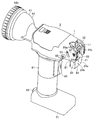
- FIG. 1 is a perspective view showing an external configuration of an endoscope linear member feeding device 1 according to an embodiment of the present invention.
- FIG. 2 is a cross-sectional view showing a configuration of the endoscope linear member feeding device 1 according to the embodiment of the present invention.
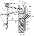
- FIG. 3 is an enlarged cross-sectional view illustrating the configuration of the nozzle 11, the fitting portion 21, and the switching portion 31 of the endoscope linear member feeding device 1 according to the embodiment of the present invention.
- FIG. 4 is an enlarged perspective view showing the external configuration of the nozzle 11, the fitting portion 21, and the switching portion 31 of the endoscope linear member delivery device 1 according to the embodiment of the present invention.
- FIG. 1 is a perspective view showing an external configuration of an endoscope linear member feeding device 1 according to an embodiment of the present invention.
- FIG. 2 is a cross-sectional view showing a configuration of the endoscope linear member feeding device 1 according to the embodiment of the present invention.
- FIG. 3 is an enlarged cross-sectional view illustrating the configuration of
- FIG. 5 is a rear perspective view showing the external configuration of the endoscope linear member delivery device 1 according to the embodiment of the present invention.
- FIG. 6 is a perspective view showing an external configuration of the endoscope linear member delivery device 1 according to the embodiment of the present invention with the cover 2 removed. In FIG. 2, the electrical connection lines are omitted.
- the endoscope linear member delivery device 1 includes a nozzle 11, a fitting unit 21, a switching unit 31, a holding unit 41, a driving unit 51, a gripping unit 61, a pedestal unit 71, and an operation unit 81. And is configured.
- the nozzle 11 is configured so that a cleaning brush B described later can be sent out to the suction cylinder side opening E1 (FIG. 9) of the endoscope E.
- the nozzle 11 is made of, for example, plastic.
- the nozzle 11 includes an introduction port 12 for introducing the cleaning brush B, a discharge port 13 for deriving the cleaning brush B, and an insertion passage 14 connecting the introduction port 12 and the discharge port 13.
- the insertion passage 14 is formed in a cylindrical shape that narrows from the inlet 12 toward the outlet 13.
- the outlet port 13 has at least a part of the end surface with respect to a direction perpendicular to the central axis of the nozzle. Inclined. In the present embodiment, one side 15 of the edge of the outlet 13 is formed to be inclined with respect to the direction orthogonal to the central axis of the nozzle.
- the fitting portion 21 has a fitting slit 24c described later, and can be fitted to the outward flange-shaped base E11 of the endoscope E.
- the outlet 13 is opposed to face the base E11. That is, the fitting portion 21 is fitted to the endoscope E so that the outlet 13 is opposed to the opening of the endoscope E.
- the fitting portion 21 includes a connection guide 22, a slide piece 23, a case body 24, and an extension plate 25.
- connection guide 22 is made of, for example, plastic.
- the body 22 a is formed in a columnar shape, the tip is formed so as to be narrowed, and the shoulder 22 b and the base 22 c are formed in a bowl shape.
- a compression spring 23a is fitted on the trunk portion 22a.
- the slide piece 23 is made of, for example, plastic.
- the slide piece 23 is slidably fitted in the case body 24.
- the slide piece 23 is provided with a turn portion 23 b for attaching the connection guide 22.
- the slide piece 23 has a ball plunger 23d with a built-in ball 23c that is urged in the pushing direction by the compression spring 23a.
- the case body 24 is made of, for example, metal.
- the case body 24 is fitted on the slide piece 23.
- the case body 24 has positioning holes 24a and 24b into which the balls 23c of the ball plunger 23d are fitted so that the position of the slide piece 23 in the sliding direction can be switched in two stages.
- the case body 24 has a fitting slit 24c so that the base E11 of the endoscope E can be slidably fitted.
- the fitting slit 24c is formed so that the nozzle 11 and the connection guide 22 are exposed.
- the case body 24 has a rotating shaft 24 d that is pivotally supported by the switching unit 31.
- the fitting portion 21 is rotatable about a rotation shaft 24d.
- the extending plate 25 extends from both sides of the case body 24 so as to be connected to the switching unit 31.
- Each of the extension plates 25 is provided with a pin 25a that is loosely fitted into the curved long hole 33 of the switching portion 31 so that the rotation range of the fitting portion 21 can be regulated.
- a positioning hole 25b (see FIG. 12) into which a ball (not shown) of a ball plunger 35 (described later) is fitted in each of the extension plates 25 so that the position of the fitting portion 21 in the rotational direction can be switched in two stages. ), 25c.
- the switching unit 31 is configured so that the intersection angle between the suction cylinder side opening E1 and the central axis AN of the nozzle 11 is switched to a plurality of stages in a state where the fitting unit 21 is fitted to the endoscope E.
- the fitting part 21 and the nozzle 11 are connected.
- the switching unit 31 is made of, for example, plastic.
- the switching unit 31 includes two support plates 32 that are opposed to each other so as to sandwich the fitting unit 21 therebetween.
- Each of the two support plates 32 includes a bearing hole 34 that supports the rotation shaft 24 d of the fitting portion 21, a curved long hole 33 that restricts the turning range of the fitting portion 21, and the fitting portion 21.
- a ball plunger 35 that can switch the rotation angle in two stages.
- the switching unit 31 supports the fitting unit 21 and can switch the intersection angle between the suction cylinder side opening E1 and the central axis AN of the nozzle 11 in two stages.
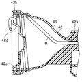
- the holding part 41 is an intersection angle between the axis AB of the cleaning brush derived from the outlet 13 of the nozzle 11 (in FIG. 2, the cleaning brush is omitted and only the axis is shown) and the central axis AN of the nozzle. However, it is comprised so that the washing brush B can be hold
- the holding part 41 is configured to include an accommodation part 42 and a connection part 43.
- the accommodating portion 42 is configured to be accommodated in a state where the cleaning brush B is wound.
- the accommodating part 42 is comprised with a plastics etc., for example.
- the accommodating part 42 has a bottomed cylindrical shape, and has a cylindrical side wall 42b that narrows toward the opening 42a, and a bottom part 42c (FIG. 5) configured by a detachable cap.
- a guide 43a (described later) is attached to the opening 42a.
- the bottom part 42c has a ring drawing hole 42d and a ring hook 42e.
- the ring B4 at the rear end of the cleaning brush B is pulled out from the ring pull-out hole 42d in the bottom portion 42c and hooked on the ring hook 42e.
- the accommodating portion 42 may not have the ring drawing hole 42d and the ring hook 42e.
- the connecting portion 43 is configured to connect the accommodating portion 42 and the inlet 12 of the nozzle 11.
- the connection portion 43 is configured to include a guide 43a and a roller 43b that is a transfer portion.
- a detachable cover 2 is provided above the connection portion 43 so that the connection portion 43 can be exposed by removing the cover 2.
- the guide 43a is provided between the roller 43b and the opening 42a of the accommodating portion 42, and is formed so as to be narrowed from the opening 42a to the roller 43b, in other words, to spread from the roller 43b to the opening 42a. Is done.
- the guide 43a can accommodate the brush B2 of the cleaning brush B, and guides the cleaning brush B fed out to the roller 43b.
- the roller 43b is arranged in the connecting portion 43 and configured to be able to transfer the cleaning brush B from at least the introduction port 12 toward the discharge port 13.
- the roller 43 b is disposed in the connection portion 43.
- the roller 43b may be disposed in the insertion path 14 of the nozzle 11 and the accommodating portion 42.
- the roller 43b is composed of a driving roller 43b1 and a driven roller 43b2 that are arranged to face each other.
- Each of the driving roller 43b1 and the driven roller 43b2 has a non-slip rubber ring 43c on the outer periphery.
- the drive roller 43 b 1 is connected to the drive shaft 52 of the drive unit 51 and is rotationally driven by the drive unit 51.
- Each of the driving roller 43b1 and the driven roller 43b2 has two gears 43d that mesh with each other at the base end.
- the driving roller 43b1 transmits the rotational force to the driven roller 43b2 by the two gears 43d, and rotates the driven roller 43b2 in the direction opposite to the driving roller 43b1.
- the driving roller 43b1 and the driven roller 43b2 can move the cleaning brush B in the direction from the introduction port 12 to the outlet port 13 or from the outlet port 13 to the inlet port 12 by being rotationally driven.
- FIG. 7 is an explanatory diagram illustrating the configuration of the drive unit 51 and the operation unit 81 of the endoscope linear member feeding device 1 according to the embodiment of the present invention.
- the drive unit 51 includes a motor 53, a control board 54, and a battery 55.
- the motor 53 transmits rotational force to a gear 53a connected to the motor shaft, a gear 53b meshing with the gear 53a, a drive shaft 52 connected to the gear 53b, and a drive roller 43b1 connected to the drive shaft 52. .
- the motor 53 is provided in the grip portion 61.
- the motor 53 is connected to the control board 54.
- the motor 53 rotationally drives the roller 43 b under the control of the control board 54.
- the control board 54 includes a circuit that controls the rotation of the motor 53.
- the control board 54 is provided in the pedestal portion 71.
- the control board 54 is connected to the battery 55 and the operation unit 81.
- the control board 54 supplies the electric power of the battery 55 to the motor 53 in accordance with an instruction input input via the operation unit 81 and rotates the motor 53.
- the battery 55 supplies power to the motor 53 under the control of the control board 54.
- the operation unit 81 includes a power switch 82 and an advance / retreat switch 83.
- the operation unit 81 is connected to the control board 54. When there is an instruction input to the operation unit 81, the instruction input is output to the control board 54.
- the power switch 82 is configured so that a power ON / OFF switching instruction can be input.
- the advance / retreat switch 83 is configured to allow the instruction of the advance / retreat of the cleaning brush B, that is, the delivery / retraction of the cleaning brush B.
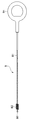
- FIG. 8 is a diagram showing an example of the cleaning brush B of the endoscope linear member feeding device 1 according to the embodiment of the present invention.
- the cleaning brush B includes a shaft B1, a brush B2, a tip end B3, and a ring B4.
- the shaft B1 is formed in an elongated shape by tightly winding a thin metal wire in a coil shape.
- the shaft B1 is inserted into the endoscope E conduit and has a length sufficient to clean the endoscope E conduit with the brush B2 provided at the tip.
- the shaft B1 is configured to have a restoring force to return to a straight line.
- Brush B2 is provided at the tip of shaft B1.
- the brush B2 is formed with a size that can pass through the endoscope E duct while being abraded. In addition, it may replace with brush B2 and may have other members which can pass through the endoscope E pipe line, such as sponge or rubber.
- the tip tip B3 is provided at the tip of the shaft B1 so that the roller 43b can easily draw the cleaning brush B.
- the ring B4 is provided at the rear end of the shaft B1 and can be hooked on the ring hook 42e of the holding portion 41.
- the ring B4 may not be provided.
- the shaft B1 is sequentially curved along the side wall 42b of the accommodating portion 42 and is accommodated in the accommodating portion 42 in a wound state.
- the cleaning brush B housed in the housing part 42 in a wound state generates a feeding force for feeding the cleaning brush B from the opening 42a of the housing part 42 by a restoring force to return to the linear shape.
- the tip B3 is pressed against the roller 43b by the feeding force of the cleaning brush B, and the brush B2 is disposed in the guide 43a.
- FIG. 9 is a diagram showing an example of an external configuration of an endoscope E to which the endoscope linear member feeding device 1 according to the embodiment of the present invention is attached.
- FIG. 10 is an explanatory diagram for explaining a state in which the nozzle 11 of the endoscope linear member delivery device 1 according to the embodiment of the present invention is directed toward the universal cord side conduit E12c.
- FIG. 11 is an explanatory view illustrating a state where the cleaning brush B of the linear member feeding device 1 for an endoscope according to the embodiment of the present invention is housed in the housing portion 42.
- FIG. 12 is an explanatory diagram illustrating a state in which the nozzle 11 of the endoscope linear member delivery device 1 according to the embodiment of the present invention is directed toward the insertion portion side pipe E12d.
- the endoscope E is configured to include a suction cylinder side opening E1 and an air / water supply cylinder side opening E2.
- the suction cylinder E12 is formed in a cylindrical shape, and has a universal cord side opening E12a and an insertion portion side opening E12b therein.
- the air / water supply cylinder E22 is formed in a cylindrical shape.
- connection guide 22 when the connection guide 22 is inserted into the air / water supply cylinder E22, the air / water supply cylinder side opening E2 is pressed against the shoulder 22b of the connection guide 22. Then, the shoulder 22b of the connection guide 22 is pushed down against the urging force of the compression spring 23a, and the base E11 of the suction cylinder E12 enters the inside of the case body 24 of the fitting portion 21 through the fitting slit 24c.
- the instruction input is input to the control board 54.
- the roller 43b is rotated by rotating the roller 43b. Then, the roller 43b pulls the tip B3 of the cleaning brush B that presses against the roller 43b, transfers the shaft B1 of the cleaning brush B to the nozzle 11, and sends the cleaning brush B from the nozzle 11 to the suction cylinder E12.
- the sent out cleaning brush B enters the universal cord side pipe line E12c from the universal cord side opening E12a, and rubs the inside of the universal cord side pipe line E12c for cleaning.
- the control board 54 rotates the motor 53 in the direction opposite to the delivery.
- the roller 43b pulls the shaft B1 of the cleaning brush B.
- the shaft B ⁇ b> 1 of the drawn cleaning brush B is curved along the side wall 42 b of the housing portion 42 and is housed in the housing portion 42 in a state of being wound in order.
- the fitting portion 21 when the fitting portion 21 is turned around the turning shaft 24 d, a ball (not shown) of the ball plunger 35 of the switching portion 31 is positioned in the positioning hole of the extension plate 25 of the fitting portion 21.
- the nozzle 11 is directed to the insertion portion side opening E12b in the suction cylinder E12.
- the cleaning brush B enters the insertion portion side conduit E12d from the insertion portion side opening E12b and cleans the inside of the insertion portion side conduit E12d.
- the cleaning brush B can be easily sent out to the universal cord side pipe line E12c and the insertion part side pipe line E12d opened in the suction cylinder E12 without damaging the cylinder inner wall.
- the cleaning brush B passes through the inside of the suction cylinder E12, the inside of the suction cylinder E12 can be cleaned together with the cleaning of the universal cord side pipe line E12c or the insertion part side pipe line E12d.
- the linear member delivery device 1 for endoscope sends out the cleaning brush B from the outside of the suction cylinder side opening E1 of the endoscope E has been described. You may comprise so that a linear member may be sent out from the outer side.
- the linear member is the cleaning brush B
- the linear member is not limited to the cleaning brush B, and for example, a treatment such as a cytodiagnosis brush, grasping forceps, or cannula It may be a tool.
- the linear member delivery apparatus for endoscopes which can send out a linear member simply without damaging a cylinder inner wall with respect to the several pipe line opened in a cylinder can be provided. .
Landscapes
- Health & Medical Sciences (AREA)
- Life Sciences & Earth Sciences (AREA)
- Surgery (AREA)
- Biomedical Technology (AREA)
- Medical Informatics (AREA)
- Optics & Photonics (AREA)
- Pathology (AREA)
- Radiology & Medical Imaging (AREA)
- Biophysics (AREA)
- Engineering & Computer Science (AREA)
- Physics & Mathematics (AREA)
- Heart & Thoracic Surgery (AREA)
- Nuclear Medicine, Radiotherapy & Molecular Imaging (AREA)
- Molecular Biology (AREA)
- Animal Behavior & Ethology (AREA)
- General Health & Medical Sciences (AREA)
- Public Health (AREA)
- Veterinary Medicine (AREA)
- Endoscopes (AREA)
- Instruments For Viewing The Inside Of Hollow Bodies (AREA)
Abstract
内視鏡用線状部材送り出し装置1は、導入口12、導出口13、および挿通路14を備えたノズル11と、内視鏡Eに嵌合する嵌合部21と、線状部材を保持する保持部41と、嵌合部21が内視鏡Eに嵌合された状態で内視鏡Eの開口とノズルの中心軸ANとの交差角度が複数の角度に切替可能に、嵌合部21とノズル11とを接続する切替部31と、を含む。
Description
本発明は、内視鏡用線状部材送り出し装置に関する。
従来、内視鏡管路を洗浄できるように、線状部材によって構成される洗浄ブラシを内視鏡管路に導出するアダプタがある。例えば、日本国特開平5-228107号公報に開示される送気送水管路掃除アダプタは、内視鏡のシリンダ内に挿入され、シリンダ内をスライドさせることにより、シリンダ内に開口する送気管路又は送水管路に洗浄ブラシの導出位置を合わせ、洗浄ブラシを導出する。
しかし、従来の送気送水管路掃除アダプタは、シリンダに挿入される際、シリンダ内壁を傷つけないように、慎重な操作を要する問題がある。
そこで、本発明は、シリンダ内に開口する複数の管路に対し、シリンダ内壁を傷つけることなく、簡便に線状部材を送り出すことができる内視鏡用線状部材送り出し装置を提供することを目的とする。
本発明の一態様の内視鏡用線状部材送り出し装置は、線状部材を導入する導入口、前記線状部材を導出する導出口、および前記導入口と前記導出口とをつなぐ挿通路を備えたノズルと、前記導出口が内視鏡の開口に対向するように、前記内視鏡に嵌合する嵌合部と、前記導出口から導出される前記線状部材の軸と、前記ノズルの中心軸との交差角度が、所定の範囲となるように前記線状部材を保持する保持部と、前記嵌合部が前記内視鏡に嵌合された状態で前記内視鏡の開口と前記ノズルの中心軸との交差角度が複数の角度に切替可能に、前記嵌合部と前記ノズルとを接続する切替部と、を含む。
以下、図面を参照しながら、本発明の実施の形態を説明する。
(構成)
図1は、本発明の実施形態に係わる、内視鏡用線状部材送り出し装置1の外観構成を示す斜視図である。図2は、本発明の実施形態に係わる、内視鏡用線状部材送り出し装置1の構成を示す断面図である。図3は、本発明の実施形態に係わる、内視鏡用線状部材送り出し装置1のノズル11、嵌合部21及び切替部31の構成を示す拡大断面図である。図4は、本発明の実施形態に係わる、内視鏡用線状部材送り出し装置1のノズル11、嵌合部21及び切替部31の外観構成を示す拡大斜視図である。図5は、本発明の実施形態に係わる、内視鏡用線状部材送り出し装置1の外観構成を示す後方斜視図である。図6は、本発明の実施形態に係わる、内視鏡用線状部材送り出し装置1のカバー2を外した状態の外観構成を示す斜視図である。図2では、電気接続線は、省略する。
図1は、本発明の実施形態に係わる、内視鏡用線状部材送り出し装置1の外観構成を示す斜視図である。図2は、本発明の実施形態に係わる、内視鏡用線状部材送り出し装置1の構成を示す断面図である。図3は、本発明の実施形態に係わる、内視鏡用線状部材送り出し装置1のノズル11、嵌合部21及び切替部31の構成を示す拡大断面図である。図4は、本発明の実施形態に係わる、内視鏡用線状部材送り出し装置1のノズル11、嵌合部21及び切替部31の外観構成を示す拡大斜視図である。図5は、本発明の実施形態に係わる、内視鏡用線状部材送り出し装置1の外観構成を示す後方斜視図である。図6は、本発明の実施形態に係わる、内視鏡用線状部材送り出し装置1のカバー2を外した状態の外観構成を示す斜視図である。図2では、電気接続線は、省略する。
内視鏡用線状部材送り出し装置1は、ノズル11と、嵌合部21と、切替部31と、保持部41と、駆動部51と、把持部61と、台座部71と、操作部81と、を有して構成される。
ノズル11は、後述する洗浄ブラシBを内視鏡Eの吸引シリンダ側開口E1(図9)に送り出すことができるように構成される。ノズル11は、例えば、プラスチック等によって構成される。ノズル11は、洗浄ブラシBを導入する導入口12、洗浄ブラシBを導出する導出口13、および導入口12及び導出口13をつなぐ挿通路14と、を備える。挿通路14は、導入口12から導出口13に向けて窄まる筒状に形成される。ノズル11の角度が切り替えられた際に、ノズル11が吸引シリンダ側開口E1の口金E11に当たらないように、導出口13は、端面の少なくとも一部をノズルの中心軸に直交する方向に対して傾斜して形成される。本実施形態では、導出口13の縁の片側15が、ノズルの中心軸に直交する方向に対して傾斜して形成される。
嵌合部21は、後述する嵌合スリット24cを有し、内視鏡Eの外向フランジ状の口金E11に嵌合可能である。嵌合部21が口金E11に嵌合すると、導出口13は、口金E11に臨むように対向する。すなわち、導出口13が内視鏡Eの開口に対向するように、嵌合部21は、内視鏡Eに嵌合する。嵌合部21は、接続ガイド22と、スライド片23と、ケース体24と、延出板25と、を有して構成される。
接続ガイド22は、例えば、プラスチック等によって構成される。接続ガイド22では、胴部22aが柱状に形成され、先端が窄まるように形成され、肩部22b及び基部22cが鍔状に形成される。接続ガイド22では、圧縮バネ23aが胴部22aに外嵌めされる。接続ガイド22がスライド片23に設けられた抉り部23bに取り付けられると、圧縮バネ23aが肩部22bに押し当たり、接続ガイド22は、接続ガイド22の先端方向に付勢される。先端方向に付勢された接続ガイド22は、基部22cがケース体24に押し当たることによって飛び出しが規制される。
スライド片23は、例えば、プラスチック等によって構成される。スライド片23は、ケース体24にスライド自在に内嵌めされる。スライド片23には、接続ガイド22を取り付けるための抉り部23bが設けられる。スライド片23は、圧縮バネ23aによって押し出す方向へ付勢されるボール23cを内蔵したボールプランジャー23dを有する。
ケース体24は、例えば、金属等によって構成される。ケース体24は、スライド片23に外嵌めされる。ケース体24は、スライド片23のスライド方向の位置を2段階に切替えできるように、ボールプランジャー23dのボール23cが嵌まる位置決め孔24a、24bを有する。ケース体24は、内視鏡Eの口金E11をスライド嵌合できるように、嵌合スリット24cを有する。嵌合スリット24cは、ノズル11及び接続ガイド22が露出するように形成される。ケース体24は、切替部31に軸支される回動軸24dを有する。嵌合部21は、回動軸24dを中心に回動自在である。
延出板25は、切替部31に接続されるように、ケース体24の両側部からそれぞれ延出する。延出板25の各々には、嵌合部21の回動範囲を規制できるように、切替部31の湾曲長孔33に遊嵌されるピン25aが設けられる。延出板25の各々には、嵌合部21の回動方向の位置を2段階に切替えることができるように、ボールプランジャー35(後述)の図示しないボールが嵌まる位置決め孔25b(図12)、25cを有する。
切替部31は、嵌合部21が内視鏡Eに嵌合された状態で吸引シリンダ側開口E1とノズル11の中心軸ANとの交差角度が複数の角度に、複数段階に切替わるように、嵌合部21及びノズル11を接続する。
切替部31は、例えば、プラスチック等によって構成される。切替部31は、嵌合部21を互いに挟むように対向配置される2つの支持板32を有する。2つの支持板32の各々には、嵌合部21の回動軸24dを軸支する軸受け孔34と、嵌合部21の回動範囲を規制する湾曲長孔33と、嵌合部21の回動角度を2段階に切替え可能であるボールプランジャー35とを有する。これにより、切替部31は、嵌合部21を軸支し、吸引シリンダ側開口E1とノズル11の中心軸ANとの交差角度を2段階に切替え可能である。
保持部41は、ノズル11の導出口13から導出される洗浄ブラシの軸AB(図2では、洗浄ブラシを省略し、軸線のみを図示している)と、ノズルの中心軸ANとの交差角度が、所定の範囲となるように洗浄ブラシBを保持することができるように構成される。保持部41は、収容部42と、接続部43とを有して構成される。
収容部42は、洗浄ブラシBが巻かれた状態で収容できるように構成される。収容部42は、例えば、プラスチック等によって構成される。収容部42は、有底筒状であり、開口42aに向けて窄まる筒状の側壁42bと、着脱自在なキャップによって構成される底部42c(図5)とを有する。
開口42aには、ガイド43a(後述)が取り付けられる。
底部42cは、リング引出し孔42d及びリング用フック42eを有する。洗浄ブラシB後端のリングB4は、底部42cのリング引出し孔42dから引き出されてリング用フック42eに掛けられる。なお、収容部42は、リング引出し孔42d及びリング用フック42eを有さなくとも構わない。
接続部43は、収容部42と、ノズル11の導入口12とをつなぐように構成される。接続部43は、ガイド43a及び移送部であるローラ43bを有して構成される。図6に示すように、接続部43の上方には、着脱自在のカバー2が覆うように設けられ、カバー2を外すことにより、接続部43を露出させることができる。
ガイド43aは、ローラ43bと、収容部42の開口42aとの間に設けられ、開口42aからローラ43bへ向けて窄まるように、言い換えれば、ローラ43bから開口42aへ向けて広がるように、形成される。ガイド43aは、洗浄ブラシBのブラシB2を収容可能であり、ローラ43bに対して繰り出される洗浄ブラシBをガイドする。
ローラ43bは、接続部43に配置され、洗浄ブラシBを少なくとも導入口12から導出口13に向けて移送することができるように構成される。図2及び図6では、接続部43にローラ43bを配置している。なお、ローラ43bは、ノズル11の挿通路14、収容部42内に配置しても構わない。
ローラ43bは、互いに対向配置される駆動ローラ43b1及び従動ローラ43b2によって構成される。駆動ローラ43b1及び従動ローラ43b2の各々は、外周に、滑り止めのゴムリング43cを有する。駆動ローラ43b1は、駆動部51の駆動軸52に連結され、駆動部51によって回転駆動される。駆動ローラ43b1及び従動ローラ43b2の各々は、基端に、互いに噛み合う2つのギア43dを有する。駆動ローラ43b1は、2つのギア43dによって回転力を従動ローラ43b2に伝達し、駆動ローラ43b1とは逆方向へ従動ローラ43b2を回転させる。駆動ローラ43b1及び従動ローラ43b2は、回転駆動することによって、導入口12から導出口13の方向へ、または、導出口13から導入口12の方向へ、洗浄ブラシBを移送可能である。
図7は、本発明の実施形態に係わる、内視鏡用線状部材送り出し装置1の駆動部51及び操作部81の構成を説明する説明図である。
図7に示すように、駆動部51は、モータ53と、制御基板54と、バッテリー55と、を有して構成される。
モータ53は、モータ軸に連結されたギア53aと、ギア53aに噛み合うギア53bと、ギア53bに連結された駆動軸52と、駆動軸52に連結された駆動ローラ43b1とに回転力を伝達させる。モータ53は、把持部61内に設けられる。モータ53は、制御基板54に接続される。モータ53は、制御基板54の制御の下、ローラ43bを回転駆動する。
制御基板54は、モータ53の回転を制御する回路を有して構成される。制御基板54は、台座部71内に設けられる。制御基板54は、バッテリー55及び操作部81に接続される。制御基板54は、操作部81を介して入力される指示入力に応じ、バッテリー55の電力をモータ53に供給し、モータ53を回転させる。
バッテリー55は、制御基板54の制御の下、モータ53に電力を供給する。
操作部81は、電源スイッチ82及び進退スイッチ83を有して構成される。操作部81は、制御基板54に接続される。操作部81に対して指示入力があると、指示入力は、制御基板54に出力される。
電源スイッチ82は、電源のON/OFF切替えの指示入力ができるように構成される。
進退スイッチ83は、洗浄ブラシBの進退、すなわち、洗浄ブラシBの送り出し、引き込みの指示入力ができるように構成される。
続いて、内視鏡用線状部材送り出し装置1に収容され、内視鏡用線状部材送り出し装置1から送り出される洗浄ブラシBについて説明をする。
図8は、本発明の実施形態に係わる、内視鏡用線状部材送り出し装置1の洗浄ブラシBの例を示す図である。
洗浄ブラシBは、シャフトB1、ブラシB2、先端チップB3、リングB4を有して構成される。
シャフトB1は、細い金属線をコイル状に密着巻きさせ、細長状に形成される。シャフトB1は、内視鏡E管路に挿入され、先端に設けられたブラシB2によって内視鏡E管路を洗浄できる十分な長さを有する。シャフトB1は、直線状に戻ろうとする復元力を有して構成される。
ブラシB2は、シャフトB1の先端に設けられる。ブラシB2は、内視鏡E管路を擦過しながら通過できる大きさによって形成される。なお、ブラシB2に代え、スポンジ又はゴム等、内視鏡E管路を擦過しながら通過できる他の部材を有しても構わない。
先端チップB3は、洗浄ブラシBをローラ43bが引き込みやすくするように、シャフトB1の先端に設けられる。
リングB4は、シャフトB1の後端に設けられ、保持部41のリング用フック42eに掛けることができる。なお、リングB4は、設けなくても構わない。
洗浄ブラシBがローラ43bの回転によって収容部42に引き込まれると、シャフトB1は、収容部42の側壁42bに沿って順次湾曲し、巻かれた状態で収容部42に収容される。
巻かれた状態で収容部42に収容された洗浄ブラシBは、直線状に戻ろうとする復元力によって収容部42の開口42aから洗浄ブラシBを繰り出すための繰出し力を生じさせる。洗浄ブラシBの繰出し力によって先端チップB3がローラ43bに押し当たり、ブラシB2は、ガイド43a内に配置される。
(作用)
続いて、内視鏡用線状部材送り出し装置1の作用について説明をする。
続いて、内視鏡用線状部材送り出し装置1の作用について説明をする。
図9は、本発明の実施形態に係わる、内視鏡用線状部材送り出し装置1が取り付けられる内視鏡Eの外観構成の例を示す図である。図10は、本発明の実施形態に係わる、内視鏡用線状部材送り出し装置1のノズル11をユニバーサルコード側管路E12cに向けた状態を説明する説明図である。図11は、本発明の実施形態に係わる、内視鏡用線状部材送り出し装置1の洗浄ブラシBを収容部42に収容させた状態を説明する説明図である。図12は、本発明の実施形態に係わる、内視鏡用線状部材送り出し装置1のノズル11を挿入部側管路E12dに向けた状態を説明する説明図である。
図9に示すように、内視鏡Eは、吸引シリンダ側開口E1と、送気送水シリンダ側開口E2とを有して構成される。吸引シリンダE12は、筒状に形成され、内部に、ユニバーサルコード側開口E12aと、挿入部側開口E12bと、を有する。送気送水シリンダE22は、筒状に形成される。
図10に示すように、接続ガイド22が送気送水シリンダE22に挿入されると、送気送水シリンダ側開口E2は、接続ガイド22の肩部22bに押し当たる。すると、接続ガイド22の肩部22bが、圧縮バネ23aの付勢力に抗して押し下がり、吸引シリンダE12の口金E11が、嵌合スリット24cから嵌合部21のケース体24の内側に入り込む。続いて、吸引シリンダE12から送気送水シリンダE22に向かう方向へ内視鏡Eがスライドされると、内視鏡Eに挿入された接続ガイド22とともにスライド片23がスライドし、ボールプランジャー23dのボール23cがケース体24の位置決め孔24bに嵌まって位置決めされる。これにより、吸引シリンダE12の口金E11がケース体24にスライドして嵌合され、ノズル11は、吸引シリンダE12内のユニバーサルコード側開口E12aに向けられる。
電源スイッチ82によって電源をON状態にし、進退スイッチ83によって洗浄ブラシBの送り出しの指示入力をすると、指示入力が制御基板54に入力され、制御基板54は、モータ53に電流を流し、モータ53を回転させ、ローラ43bを回転させる。すると、ローラ43bは、ローラ43bに押し当たる洗浄ブラシBの先端チップB3を引き込み、洗浄ブラシBのシャフトB1をノズル11に移送し、ノズル11から吸引シリンダE12に洗浄ブラシBを送り出す。送り出された洗浄ブラシBは、ユニバーサルコード側開口E12aからユニバーサルコード側管路E12cに入り、ユニバーサルコード側管路E12c内を擦過して洗浄する。
進退スイッチ83によって洗浄ブラシBの引き込みの指示入力をすると、制御基板54は、送り出しとは逆方向に、モータ53を回転させる。モータ53が回転すると、ローラ43bは、洗浄ブラシBのシャフトB1を引き込む。図11に示すように、引き込まれた洗浄ブラシBのシャフトB1は、収容部42の側壁42bに沿って湾曲し、順次巻かれた状態で収容部42に収容される。洗浄ブラシBの先端の先端チップB3がローラ43bを通過すると、洗浄ブラシBの引き込みは完了する。
図12に示すように、回動軸24dを中心に嵌合部21を回動させると、切替部31のボールプランジャー35の図示しないボールが、嵌合部21の延出板25の位置決め孔25bに嵌まり、ノズル11は、吸引シリンダE12内の挿入部側開口E12bに向けられる。進退スイッチ83による洗浄ブラシBの送り出しをするための指示入力があると、洗浄ブラシBは、挿入部側開口E12bから挿入部側管路E12dに入り、挿入部側管路E12d内を洗浄する。
実施形態によれば、吸引シリンダE12内に開口するユニバーサルコード側管路E12c及び挿入部側管路E12dに対し、シリンダ内壁を傷つけることなく、簡便に洗浄ブラシBを送り出すことができる
実施形態によれば、洗浄ブラシBは、吸引シリンダE12内を通過するため、ユニバーサルコード側管路E12c又は挿入部側管路E12dの洗浄とともに、吸引シリンダE12内も洗浄可能である。
実施形態によれば、洗浄ブラシBは、吸引シリンダE12内を通過するため、ユニバーサルコード側管路E12c又は挿入部側管路E12dの洗浄とともに、吸引シリンダE12内も洗浄可能である。
なお、実施形態では、内視鏡用線状部材送り出し装置1は、内視鏡Eの吸引シリンダ側開口E1の外側から洗浄ブラシBを送り出す例を説明したが、内視鏡の他の開口の外側から線状部材を送り出すように構成されても構わない。
なお、実施形態では、線状部材が洗浄ブラシBである例を説明しているが、線状部材は、洗浄ブラシBに限られず、例えば、細胞診ブラシ、把持鉗子、又は、カニューラ等の処置具であっても構わない。
本発明は、上述した実施の形態に限定されるものではなく、本発明の要旨を変えない範囲において、種々の変更、改変等が可能である。
本発明によれば、シリンダ内に開口する複数の管路に対し、シリンダ内壁を傷つけることなく、簡便に線状部材を送り出すことができる内視鏡用線状部材送り出し装置を提供することができる。
本出願は、2016年1月28日に日本国に出願された特願2016-014472号を優先権主張の基礎として出願するものであり、上記の開示内容は、本願明細書、請求の範囲に引用されるものとする。
Claims (5)
- 線状部材を導入する導入口、前記線状部材を導出する導出口、および前記導入口と前記導出口とをつなぐ挿通路を備えたノズルと、
前記導出口が内視鏡の開口に対向するように、前記内視鏡に嵌合する嵌合部と、
前記導出口から導出される前記線状部材の軸と、前記ノズルの中心軸との交差角度が、所定の範囲となるように前記線状部材を保持する保持部と、
前記嵌合部が前記内視鏡に嵌合された状態で前記内視鏡の開口と前記ノズルの中心軸との交差角度が複数の角度に切替可能に、前記嵌合部と前記ノズルとを接続する切替部と、を含むことを特徴とする内視鏡用線状部材送り出し装置。 - 前記切替部は、前記内視鏡の開口と前記ノズルの中心軸との交差角度を複数段階に切替え、
前記導出口は、端面の少なくとも一部を前記ノズルの中心軸に直交する方向に対して傾斜して形成されることを特徴とする請求項1に記載の内視鏡用線状部材送り出し装置。 - 前記保持部は、
前記線状部材が巻かれた状態で収容される収容部と、
前記収容部と前記導入口とをつなぐ接続部と、を含むことを特徴とする請求項1に記載の内視鏡用線状部材送り出し装置。 - 前記挿通路または前記保持部に配置され、前記線状部材を少なくとも前記導入口から前記導出口に向けて移送する移送部を含むことを特徴とする請求項1に記載の内視鏡用線状部材送り出し装置。
- 前記嵌合部は、前記内視鏡の吸引シリンダに嵌合することを特徴とする請求項1に記載の内視鏡用線状部材送り出し装置。
Priority Applications (4)
| Application Number | Priority Date | Filing Date | Title |
|---|---|---|---|
| CN201680004155.XA CN107405065B (zh) | 2016-01-28 | 2016-09-30 | 内窥镜用线状构件送出装置 |
| JP2017502280A JP6113390B1 (ja) | 2016-01-28 | 2016-09-30 | 内視鏡用線状部材送り出し装置 |
| EP16869375.2A EP3241486A4 (en) | 2016-01-28 | 2016-09-30 | Linear member delivering device for endoscope |
| US15/619,603 US10194784B2 (en) | 2016-01-28 | 2017-06-12 | Linear member delivery device for endoscope |
Applications Claiming Priority (2)
| Application Number | Priority Date | Filing Date | Title |
|---|---|---|---|
| JP2016014472 | 2016-01-28 | ||
| JP2016-014472 | 2016-01-28 |
Related Child Applications (1)
| Application Number | Title | Priority Date | Filing Date |
|---|---|---|---|
| US15/619,603 Continuation US10194784B2 (en) | 2016-01-28 | 2017-06-12 | Linear member delivery device for endoscope |
Publications (1)
| Publication Number | Publication Date |
|---|---|
| WO2017130465A1 true WO2017130465A1 (ja) | 2017-08-03 |
Family
ID=59397558
Family Applications (1)
| Application Number | Title | Priority Date | Filing Date |
|---|---|---|---|
| PCT/JP2016/079091 Ceased WO2017130465A1 (ja) | 2016-01-28 | 2016-09-30 | 内視鏡用線状部材送り出し装置 |
Country Status (5)
| Country | Link |
|---|---|
| US (1) | US10194784B2 (ja) |
| EP (1) | EP3241486A4 (ja) |
| JP (1) | JP6113390B1 (ja) |
| CN (1) | CN107405065B (ja) |
| WO (1) | WO2017130465A1 (ja) |
Cited By (1)
| Publication number | Priority date | Publication date | Assignee | Title |
|---|---|---|---|---|
| JP2019130086A (ja) * | 2018-01-31 | 2019-08-08 | 興研株式会社 | 内視鏡洗浄装置 |
Families Citing this family (3)
| Publication number | Priority date | Publication date | Assignee | Title |
|---|---|---|---|---|
| US10716623B2 (en) * | 2016-05-05 | 2020-07-21 | Covidien Lp | Bronchoscope coupler |
| US20200178783A1 (en) * | 2018-12-05 | 2020-06-11 | Asp Global Manufacturing Gmbh | Apparatus and system for guiding a cleaning implement and a method of use thereof |
| USD989299S1 (en) * | 2021-07-23 | 2023-06-13 | Intuitive Surgical Operations, Inc. | Connector assembly for a surgical instrument |
Citations (7)
| Publication number | Priority date | Publication date | Assignee | Title |
|---|---|---|---|---|
| JPS5846933A (ja) * | 1981-09-17 | 1983-03-18 | オリンパス光学工業株式会社 | 内視鏡の吸引管路洗浄装置 |
| JPH05228107A (ja) | 1992-02-19 | 1993-09-07 | Asahi Optical Co Ltd | 内視鏡の送気送水管路掃除具 |
| JP2004208961A (ja) * | 2002-12-27 | 2004-07-29 | Olympus Corp | 内視鏡管路洗滌装置 |
| JP2005058258A (ja) * | 2003-08-11 | 2005-03-10 | Koken Ltd | 内視鏡洗滌用ブラシの挿入案内具およびその使用方法 |
| JP2011120788A (ja) * | 2009-12-11 | 2011-06-23 | Koken Ltd | 内視鏡洗滌用ブラシの案内具 |
| JP2016014472A (ja) | 2014-06-13 | 2016-01-28 | 日本精工株式会社 | スナップリング |
| KR20160097681A (ko) * | 2015-02-09 | 2016-08-18 | 이동규 | 내시경 청소기, 카세트 교체형 내시경 청소기 및 내시경 청소용 브러시 카세트 |
Family Cites Families (6)
| Publication number | Priority date | Publication date | Assignee | Title |
|---|---|---|---|---|
| EP0075188B1 (en) | 1981-09-17 | 1987-11-19 | Olympus Optical Co., Ltd. | A suction device for an endoscope |
| JP2008161383A (ja) * | 2006-12-27 | 2008-07-17 | Olympus Medical Systems Corp | 内視鏡洗浄消毒装置 |
| JP5032272B2 (ja) * | 2007-11-12 | 2012-09-26 | オリンパスメディカルシステムズ株式会社 | 内視鏡洗浄消毒装置 |
| JP5220435B2 (ja) * | 2008-02-20 | 2013-06-26 | オリンパスメディカルシステムズ株式会社 | 洗浄チューブ、及び内視鏡洗浄消毒装置 |
| US9126241B2 (en) * | 2009-11-20 | 2015-09-08 | Ali Waqar Majeed | Cleaning apparatus |
| EP2962619A4 (en) * | 2013-02-27 | 2017-01-11 | Olympus Corporation | Insertion/removal-support tool for endoscopic instrument |
-
2016
- 2016-09-30 EP EP16869375.2A patent/EP3241486A4/en not_active Withdrawn
- 2016-09-30 CN CN201680004155.XA patent/CN107405065B/zh active Active
- 2016-09-30 JP JP2017502280A patent/JP6113390B1/ja active Active
- 2016-09-30 WO PCT/JP2016/079091 patent/WO2017130465A1/ja not_active Ceased
-
2017
- 2017-06-12 US US15/619,603 patent/US10194784B2/en active Active
Patent Citations (7)
| Publication number | Priority date | Publication date | Assignee | Title |
|---|---|---|---|---|
| JPS5846933A (ja) * | 1981-09-17 | 1983-03-18 | オリンパス光学工業株式会社 | 内視鏡の吸引管路洗浄装置 |
| JPH05228107A (ja) | 1992-02-19 | 1993-09-07 | Asahi Optical Co Ltd | 内視鏡の送気送水管路掃除具 |
| JP2004208961A (ja) * | 2002-12-27 | 2004-07-29 | Olympus Corp | 内視鏡管路洗滌装置 |
| JP2005058258A (ja) * | 2003-08-11 | 2005-03-10 | Koken Ltd | 内視鏡洗滌用ブラシの挿入案内具およびその使用方法 |
| JP2011120788A (ja) * | 2009-12-11 | 2011-06-23 | Koken Ltd | 内視鏡洗滌用ブラシの案内具 |
| JP2016014472A (ja) | 2014-06-13 | 2016-01-28 | 日本精工株式会社 | スナップリング |
| KR20160097681A (ko) * | 2015-02-09 | 2016-08-18 | 이동규 | 내시경 청소기, 카세트 교체형 내시경 청소기 및 내시경 청소용 브러시 카세트 |
Non-Patent Citations (1)
| Title |
|---|
| See also references of EP3241486A4 |
Cited By (1)
| Publication number | Priority date | Publication date | Assignee | Title |
|---|---|---|---|---|
| JP2019130086A (ja) * | 2018-01-31 | 2019-08-08 | 興研株式会社 | 内視鏡洗浄装置 |
Also Published As
| Publication number | Publication date |
|---|---|
| US10194784B2 (en) | 2019-02-05 |
| CN107405065A (zh) | 2017-11-28 |
| CN107405065B (zh) | 2019-08-20 |
| JP6113390B1 (ja) | 2017-04-12 |
| JPWO2017130465A1 (ja) | 2018-02-01 |
| EP3241486A1 (en) | 2017-11-08 |
| US20170273544A1 (en) | 2017-09-28 |
| EP3241486A4 (en) | 2018-11-21 |
Similar Documents
| Publication | Publication Date | Title |
|---|---|---|
| JP6113390B1 (ja) | 内視鏡用線状部材送り出し装置 | |
| JP5097931B2 (ja) | 内視鏡用自動復帰式シリンジ | |
| JP6723942B2 (ja) | 内視鏡 | |
| EP1839565A2 (en) | Endoscope washing and disinfecting apparatus and endoscope conduit washing brush cassette | |
| CN109922705B (zh) | 内窥镜、内窥镜的线材安装方法以及内窥镜的线材拆卸方法 | |
| EP2016914A3 (en) | Insertion assisting device and endoscope apparatus | |
| EP1844699A3 (en) | Apparatus for washing and disinfecting endoscope and brush unit for washing ducts of endoscope | |
| JP5284197B2 (ja) | 掃除用具及びこれを備えた電気掃除機 | |
| US8016753B2 (en) | Endoscope | |
| JPH10272097A (ja) | 内視鏡の管路洗浄装置 | |
| JP2006247289A5 (ja) | ||
| JP6099858B1 (ja) | 線状部材移送装置 | |
| CN211270634U (zh) | 一种内镜用清洗管 | |
| JPWO2015163096A1 (ja) | 内視鏡用ガイド部材のための保持機構と内視鏡用ガイド部材と内視鏡 | |
| JP5696611B2 (ja) | 床面吸込具、及び、この床面吸込具を用いた電気掃除機 | |
| JP6805104B2 (ja) | 洗浄用の内視鏡保持具、洗浄装置、及び内視鏡の洗浄方法 | |
| CN108882830A (zh) | 内窥镜 | |
| JP5695545B2 (ja) | 内視鏡 | |
| CN218605534U (zh) | 一种胃肠镜自动洗刷器 | |
| JP5854730B2 (ja) | 電気掃除機 | |
| KR20190035344A (ko) | 관 내부 청소 장치 | |
| JP2004141285A (ja) | 内視鏡の流体噴出装置 | |
| JP4303000B2 (ja) | 内視鏡の管路洗浄装置及び管路洗浄方法 | |
| RU87886U1 (ru) | Беспроводной пылесос | |
| JP2002000563A (ja) | 内視鏡の管路内清掃用ブラシ及びその使用方法 |
Legal Events
| Date | Code | Title | Description |
|---|---|---|---|
| ENP | Entry into the national phase |
Ref document number: 2017502280 Country of ref document: JP Kind code of ref document: A |
|
| REEP | Request for entry into the european phase |
Ref document number: 2016869375 Country of ref document: EP |
|
| 121 | Ep: the epo has been informed by wipo that ep was designated in this application |
Ref document number: 16869375 Country of ref document: EP Kind code of ref document: A1 |
|
| NENP | Non-entry into the national phase |
Ref country code: DE |