WO2017130862A1 - 生体試料撮像装置及び生体試料撮像方法 - Google Patents
生体試料撮像装置及び生体試料撮像方法 Download PDFInfo
- Publication number
- WO2017130862A1 WO2017130862A1 PCT/JP2017/001955 JP2017001955W WO2017130862A1 WO 2017130862 A1 WO2017130862 A1 WO 2017130862A1 JP 2017001955 W JP2017001955 W JP 2017001955W WO 2017130862 A1 WO2017130862 A1 WO 2017130862A1
- Authority
- WO
- WIPO (PCT)
- Prior art keywords
- biological sample
- imaging
- imaging device
- liquid
- downstream end
- Prior art date
- Legal status (The legal status is an assumption and is not a legal conclusion. Google has not performed a legal analysis and makes no representation as to the accuracy of the status listed.)
- Ceased
Links
Images








Classifications
-
- G—PHYSICS
- G01—MEASURING; TESTING
- G01N—INVESTIGATING OR ANALYSING MATERIALS BY DETERMINING THEIR CHEMICAL OR PHYSICAL PROPERTIES
- G01N15/00—Investigating characteristics of particles; Investigating permeability, pore-volume or surface-area of porous materials
- G01N15/10—Investigating individual particles
- G01N15/14—Optical investigation techniques, e.g. flow cytometry
- G01N15/1404—Handling flow, e.g. hydrodynamic focusing
-
- G—PHYSICS
- G01—MEASURING; TESTING
- G01N—INVESTIGATING OR ANALYSING MATERIALS BY DETERMINING THEIR CHEMICAL OR PHYSICAL PROPERTIES
- G01N15/00—Investigating characteristics of particles; Investigating permeability, pore-volume or surface-area of porous materials
-
- G—PHYSICS
- G01—MEASURING; TESTING
- G01N—INVESTIGATING OR ANALYSING MATERIALS BY DETERMINING THEIR CHEMICAL OR PHYSICAL PROPERTIES
- G01N15/00—Investigating characteristics of particles; Investigating permeability, pore-volume or surface-area of porous materials
- G01N15/10—Investigating individual particles
- G01N15/14—Optical investigation techniques, e.g. flow cytometry
- G01N15/1456—Optical investigation techniques, e.g. flow cytometry without spatial resolution of the texture or inner structure of the particle, e.g. processing of pulse signals
- G01N15/1459—Optical investigation techniques, e.g. flow cytometry without spatial resolution of the texture or inner structure of the particle, e.g. processing of pulse signals the analysis being performed on a sample stream
-
- G—PHYSICS
- G01—MEASURING; TESTING
- G01N—INVESTIGATING OR ANALYSING MATERIALS BY DETERMINING THEIR CHEMICAL OR PHYSICAL PROPERTIES
- G01N33/00—Investigating or analysing materials by specific methods not covered by groups G01N1/00 - G01N31/00
- G01N33/48—Biological material, e.g. blood, urine; Haemocytometers
- G01N33/483—Physical analysis of biological material
- G01N33/487—Physical analysis of biological material of liquid biological material
- G01N33/493—Physical analysis of biological material of liquid biological material urine
-
- G—PHYSICS
- G01—MEASURING; TESTING
- G01N—INVESTIGATING OR ANALYSING MATERIALS BY DETERMINING THEIR CHEMICAL OR PHYSICAL PROPERTIES
- G01N35/00—Automatic analysis not limited to methods or materials provided for in any single one of groups G01N1/00 - G01N33/00; Handling materials therefor
- G01N35/08—Automatic analysis not limited to methods or materials provided for in any single one of groups G01N1/00 - G01N33/00; Handling materials therefor using a stream of discrete samples flowing along a tube system, e.g. flow injection analysis
-
- G—PHYSICS
- G01—MEASURING; TESTING
- G01N—INVESTIGATING OR ANALYSING MATERIALS BY DETERMINING THEIR CHEMICAL OR PHYSICAL PROPERTIES
- G01N15/00—Investigating characteristics of particles; Investigating permeability, pore-volume or surface-area of porous materials
- G01N15/06—Investigating concentration of particle suspensions
-
- G—PHYSICS
- G01—MEASURING; TESTING
- G01N—INVESTIGATING OR ANALYSING MATERIALS BY DETERMINING THEIR CHEMICAL OR PHYSICAL PROPERTIES
- G01N15/00—Investigating characteristics of particles; Investigating permeability, pore-volume or surface-area of porous materials
- G01N15/10—Investigating individual particles
- G01N15/14—Optical investigation techniques, e.g. flow cytometry
- G01N15/1404—Handling flow, e.g. hydrodynamic focusing
- G01N15/1409—Handling samples, e.g. injecting samples
-
- G—PHYSICS
- G01—MEASURING; TESTING
- G01N—INVESTIGATING OR ANALYSING MATERIALS BY DETERMINING THEIR CHEMICAL OR PHYSICAL PROPERTIES
- G01N15/00—Investigating characteristics of particles; Investigating permeability, pore-volume or surface-area of porous materials
- G01N15/04—Investigating sedimentation of particle suspensions
- G01N15/042—Investigating sedimentation of particle suspensions by centrifuging and investigating centrifugates
- G01N2015/045—Investigating sedimentation of particle suspensions by centrifuging and investigating centrifugates by optical analysis
-
- H—ELECTRICITY
- H04—ELECTRIC COMMUNICATION TECHNIQUE
- H04N—PICTORIAL COMMUNICATION, e.g. TELEVISION
- H04N23/00—Cameras or camera modules comprising electronic image sensors; Control thereof
Definitions
- the present invention relates to a biological sample imaging apparatus and a biological sample imaging method, and more particularly to imaging of a liquid biological sample containing particles such as urine and blood.
- the urine sample contains particles such as red blood cells, white blood cells, epithelial cells, and urine casts, and observing these particles in the urine sample is effective for diagnosing kidney and urinary tract diseases.
- the following prior art documents disclose an apparatus for imaging particles contained in a biological sample such as a urine sample.
- a concentrating effect is exerted on the particles in the biological sample. That is, according to fluid dynamics, the flow rate of the biological sample increases as it approaches the central axis, and particles in the biological sample gather near the central axis of the liquid flow channel, which has the highest flow rate.
- This concentrating effect works greatly for large-sized particles. As a result, the large-sized particles are caused to flow downstream at a high flow rate, and the concentration of the large-sized particles increases near the downstream end of the biological sample flowing through the liquid flow path (at the top of the biological sample). .
- one of the objects of the present invention is to provide a biological sample imaging apparatus and biological sample imaging method capable of arranging a large number of large-sized particles in a biological sample in a sufficiently large number within an imaging range. There is.
- a biological sample imaging device includes a liquid flow path in which a liquid biological sample containing particles circulates, a liquid channel having an imaging range for imaging particles included in the biological sample at a predetermined position, and a container
- a pump that circulates the biological sample introduced into the liquid channel in the forward direction from the upstream side to the downstream side, or the opposite direction, and the biological sample introduced into the liquid channel in the forward direction
- a pump control unit for causing the pump to sequentially perform a first operation to be performed and a second operation for circulating the biological sample in the reverse direction; and the biological sample remaining in the liquid channel after the second operation.
- An imaging unit that images the contained particles in the imaging range.
- the biological sample imaging method includes a first step of introducing a biological sample containing particles into a liquid channel, and the biological sample introduced into the liquid channel from an upstream side to a downstream side.
- a second step for flowing in the forward direction toward the first a third step for flowing the biological sample in the reverse direction after the second step, and the biological sample remaining in the liquid channel after the third step.
- a biological sample imaging apparatus and a biological sample imaging method capable of arranging a large number of large-sized particles in a biological sample in a sufficient number and appropriately dispersed in the imaging range.
- FIG. 1 is a configuration diagram of a biological sample imaging apparatus according to an embodiment of the present invention.
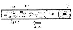
- FIG. 2A is a diagram schematically showing the inside of the liquid flow path when the pump is driven in the forward direction.
- FIG. 2B is a diagram schematically showing the inside of the liquid channel when the pump is driven in the reverse direction.
- FIG. 3 is a distribution diagram of large particles and small particles in a biological sample immediately after the pump is driven in the forward direction.
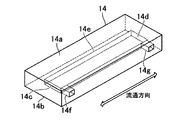
- FIG. 4A is a perspective view showing an imaging cell.
- FIG. 4B is a diagram schematically showing a cross section of the imaging cell immediately after the biological sample is filled.
- FIG. 4C is a diagram schematically showing a cross section of the imaging cell after a predetermined time has elapsed since the biological sample was filled.
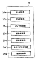
- FIG. 5 is a functional block diagram of the data processing apparatus.
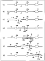
- FIG. 6 is a diagram showing, in time series, a state in which a substance such as a biological sample flows through the liquid channel.
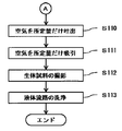
- FIG. 7A is an operation flowchart of the biological sample imaging device according to the embodiment of the present invention.
- FIG. 7B is an operation flowchart of the biological sample imaging device according to the embodiment of the present invention.
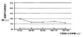
- FIG. 8A is a distribution diagram of large particles after the biological sample is circulated in the liquid channel by the biological sample imaging device according to the embodiment of the present invention.
- FIG. 8B is a distribution diagram of small particles after the biological sample is circulated in the liquid channel by the biological sample imaging device according to the embodiment of the present invention.
- FIG. 9 is a diagram illustrating another example of pump control by the biological sample imaging device according to the embodiment of the present invention.
- FIG. 1 is a configuration diagram of a biological sample imaging apparatus according to an embodiment of the present invention.
- a biological sample imaging apparatus 10 shown in the figure is an apparatus for imaging particles in a liquid biological sample containing particles.
- a urine sample is used as such a biological sample, and particles such as red blood cells, white blood cells, epithelial cells, and urine columns in the urine sample are photographed by the biological sample imaging device 10.
- the epithelial cells are squamous epithelial cells, transitional epithelial cells, tubular epithelial cells and the like.
- the urine column is a glass column, epithelial column, erythrocyte column, leukocyte column, fat column, granule column, waxy column or the like.
- the biological sample may be blood, body cavity fluid or the like in addition to urine.
- the biological sample may be a liquid itself collected from a living body or may be diluted with another liquid.
- the biological sample may be obtained by dissolving particles collected from a living body in a liquid.
- particles having a particle diameter of around 7 ⁇ m such as red blood cells and white blood cells
- particles having a particle diameter of 20 to 40 ⁇ m such as epithelial cells and urine columns, are referred to as large particles.
- the biological sample imaging device 10 includes a liquid flow path 40, a light source 12, an objective lens 16, a camera 18, a data processing device 20, a display device 22, a syringe pump 24, and a cleaning liquid container 26. , A suction nozzle actuator 30, a cleaning tank 36, and a waste liquid container 38.
- the liquid flow path 40 includes a hollow rod-like suction nozzle 32, a liquid flow path in the second sensor 28b, a liquid flow path in the first sensor 28a, and the imaging cell 14, which are arranged in this order from the upstream side. Furthermore, a silicon tube or other tube 41 connected to them is also included.
- the imaging cell 14 is formed in a flat plate shape with a light-transmitting material, and a urine sample flows through an inner space provided in a flattened rectangular parallelepiped shape, and the urine sample is held in the inner space. A urine sample can be observed from the outside in a state.
- the upstream end of the liquid channel 40 is the tip of the suction nozzle 32, and the downstream end is the suction / discharge port of the syringe pump 24.
- the internal space of the liquid flow path 40 has a circular cross section except for the portion of the imaging cell 14.
- a first position A is set on the liquid flow path 40 on the upstream side of the imaging cell 14, and a second position B is set on the further upstream side of the first position A. The first position A and the second position B will be described in detail later.
- the light source 12 includes an LED or other light emitting element and a convex lens, and is disposed immediately below the imaging cell 14.
- the light emitted from the light emitting element is converted into parallel light by the convex lens, and enters the imaging cell 14 formed of a material having translucency from below.
- the camera 18 is a CCD image sensor or a CMOS image sensor, and is disposed directly above the imaging cell 14 together with the objective lens 16.
- the objective lens 16 and the camera 18 constitute a microscopic camera, and the captured image data of the urine sample filled in the imaging cell 14 is generated.
- the display device 22 is a display panel such as an LCD or an OLED, and displays image data generated by the camera 18 and other information.
- the data processing device 20 is a computer system mainly composed of a CPU and a memory, and a camera 18 and a display device 22 are connected to the data processing device 20.
- the data processing device 20 includes a light source 12, a piston actuator 24a of the syringe pump 24, an electromagnetic valve provided in a tube between the syringe pump 24 and the cleaning liquid container 26, a first sensor 28a, and a second sensor.
- the solenoid valve provided in the drain tube of 28b, the suction nozzle actuator 30, and the washing tank 36 is also connected.
- An image analysis program and various control programs are installed in the data processing device 20, and image data generated by the camera 18 is displayed on the display unit 22.
- the image data generated by the camera 18 is analyzed, and the particles projected there are detected.
- the data processing device 20 controls the piston actuator 24a, the suction nozzle actuator 30, and each electromagnetic valve. Note that some or all of the various functions performed by the data processing apparatus 20 may be realized by other types of hardware such as an ASIC and an FPGA.
- the syringe pump 24 generates a negative pressure or a positive pressure with respect to the liquid channel 40, and causes the liquid or gas to flow in the forward direction from the upstream end to the downstream end or in the opposite direction in the liquid channel 40. Specifically, the syringe pump 24 sucks a urine sample from a sample container 34 such as a test tube to fill the urine sample into the internal space of the imaging cell 14 or fills the liquid or gas in the liquid flow path 40 with the urine sample. Or backflow.
- the syringe pump 24 includes a cylinder and a piston inserted into the cylinder, and a piston actuator 24a is attached to the piston.
- the piston actuator 24a which is a motor or other electric drive means, pulls out the piston from the cylinder (forward driving) or conversely pushes the piston into the cylinder (reverse driving) in accordance with a command from the data processing device 20.
- An opening is provided in the side surface of the cylinder, and a tube that connects the inside of the cleaning liquid container 26 and the inside of the syringe pump 24 is connected to the opening.
- the suction nozzle actuator 30 moves the suction nozzle 32 up, down, left and right in accordance with instructions from the data processing device 20. Specifically, a plurality of sample containers 34 held in a rack are transported to a suction position of the biological sample imaging device 10 by a transport means such as a belt conveyor. The suction nozzle 32 is inserted into one of the sample containers 34 that is sequentially selected by the data processing device 20, or conversely, the suction nozzle 32 is pulled out from the sample container 34. Further, when the suction nozzle 32 and the liquid flow path 40 are cleaned, the suction nozzle 32 is inserted into the cleaning tank 36.
- Both the first sensor 28a and the second sensor 28b output data corresponding to the type of the object (liquid or gas) flowing through the sensor position in the liquid flow path 40.
- conductivity sensors may be used as the first sensor 28a and the second sensor 28b.
- the conductivity sensor is provided in contact with a biological sample passing through the liquid flow path 40.
- the conductivity sensor includes two tubular electrodes spaced apart on the upstream side and the downstream side, and outputs the conductivity of an object flowing between these electrodes.
- an optical sensor may be used as the first sensor 28a and the second sensor 28b.
- the optical sensor includes a light emitting part and a light receiving part arranged so as to face each other through a tube through which a biological sample flows, and irradiates light from the light emitting part to an object flowing through the tube and reflects the intensity of light transmitted through the object.
- the received signal is output from the light receiving unit.
- FIG. 2A is a diagram schematically showing the inside of the tube 41 being driven forward by the syringe pump 24.
- the liquid flow path 40 such as the tube 41 is initially filled with the cleaning liquid 102.
- the biological sample 104 is filled in the imaging cell 14, a small amount of air 100 is first aspirated. Thereafter, the biological sample 104 is sucked from the sample container 34 by a predetermined amount. Therefore, as shown in FIG. 2A, the air 100 (air gap) is positioned upstream of the cleaning liquid 102, and the biological sample 104 is positioned further upstream.
- the flow velocity becomes faster as it approaches the central axis. Then, the particles in the biological sample gather near the central axis of the liquid channel 40 having the highest flow velocity.
- This concentrating effect works greatly on large particles such as epithelial cells 114 and urine cylinders 116. As a result, the epithelial cells 114 and the urine column 116 are caused to flow downstream at a high flow rate. As shown in FIG. 2A, in the vicinity of the downstream end 104a of the biological sample 104 flowing through the liquid flow path 40, epithelial cells. The density of 114 and the urine column 116 is increased. Note that the red blood cell 112 and the white blood cell 110 have a sufficiently small particle size as compared with the flow velocity profile of the liquid flow path 40, so that the concentrating effect can be ignored.
- FIG. 3 is a distribution diagram of large particles and small particles in the biological sample 104 immediately after the syringe pump 24 is driven in the forward direction.
- the vertical axis represents the value obtained by dividing the particle density (number of particles per unit volume) in the liquid channel 40 by the particle density in the sample container 34.
- the horizontal axis indicates the volume from the downstream end 104a of the biological sample 104.
- the particle density of large particles such as epithelial cells 114 and urine column 116 increases. That is, the particle density ratio of large particles reaches nearly 300% in the vicinity of the downstream end 104a of the biological sample 104.
- the effect of concentrating large particles can be obtained by circulating the biological sample 104 through the liquid channel 40. For this reason, by photographing the vicinity of the downstream end 104a of the biological sample 104 after flowing through the liquid flow path 40, large particles such as the epithelial cells 114 and the urine column 116 can be efficiently photographed.
- the particle density ratio of small particles such as red blood cells 112 and white blood cells 110 decreases as they move from the upstream end to the downstream side of the biological sample 104.
- the particle density ratio of the small particles is less than 100%. This is because, as described above, the concentrating effect hardly acts on the small particles, and the biological sample 104 is diluted as it moves downstream by the cleaning liquid 102 adhering to the inner wall surface of the liquid channel 40. , Is considered as the reason.
- the density of large particles such as the epithelial cells 114 and the urine column 116 can be increased in the vicinity of the downstream end 104 a of the biological sample 104.
- the imaging cell 14 has an internal space that expands in the horizontal direction as will be described in detail later, and all or a part of this internal space is set as an imaging range by the camera 18. If the downstream end 104a of the biological sample 104 is positioned within the imaging range, large particles concentrate on a part of the imaging range and overlap each other, making it difficult to project individual particles on the image. .
- pump control is performed in which large particles concentrated near the downstream end 104a of the biological sample 104 are dispersed again. That is, in the present embodiment, the forward drive of the syringe pump 24 is temporarily stopped immediately before the biological sample 104 enters the internal space of the imaging cell 14. That is, when the downstream end 104a of the biological sample 104 reaches the first position A (see FIG. 1) set on the upstream side of the imaging cell 14, the operation of the syringe pump 24 is stopped. Next, the syringe pump 24 is driven in the reverse direction until the downstream end 104a of the biological sample 104 reaches the second position B. The second position B is set further upstream than the first position A. That is, the biological sample 104 is pushed back upstream.
- FIG. 2B is a diagram schematically showing the inside of the liquid flow path 40 while the syringe pump 24 is driven in the reverse direction.
- the biological sample 104 moves this time toward the upstream side, that is, the suction nozzle 32 side.
- the concentrating effect acts greatly on large particles such as epithelial cells 114 and urine column 116.
- the large particles concentrated near the downstream end 104a move in the upstream direction relative to the small particles, as shown in FIG. 2B.
- the syringe pump 24 is driven in the reverse direction by a fixed volume, the large particles concentrated on the downstream end 104a can be suitably dispersed to a portion away from the downstream end 104a.
- the syringe pump 24 When the downstream end 104a of the biological sample 104 reaches the second position B, the syringe pump 24 is temporarily stopped, and this time, the syringe pump 24 is driven forward until the downstream end 104a of the biological sample 104 reaches the third position C. .
- the third position C is set on the downstream side of the imaging cell 14 in the liquid flow path 40. By doing so, the biological sample 104 can be filled into the internal space of the imaging cell 14.
- FIG. 4A is a perspective view of the imaging cell 14.
- the imaging cell 14 has an internal space 14e for holding a urine sample, and an inflow path 14f and an outflow path 14g that connect the internal space 14e and the outside.
- the imaging cell 14 is flat and has a rectangular parallelepiped outer shape extending in one direction.
- the internal space 14 e also has a rectangular parallelepiped shape that extends flat in one direction, and is provided along the outer shape of the imaging cell 14.
- the imaging cell 14 is installed so that the bottom surface of the internal space 14e is horizontal.
- the internal space 14e is provided in parallel with each other, and is sandwiched between the thin plate portion 14a and the thin plate portion 14b arranged to face each other.
- at least the thin plate portion 14a and the thin plate portion 14b of the imaging cell 14 are made of a light-transmitting material such as glass or resin.
- the internal space 14e has a rectangular parallelepiped shape extending in one direction as described above, and one end side surface in the longitudinal direction is the upstream end 14c, and the other end side surface is the downstream end 14d.
- an inflow path 14 f connected to the opening on the side surface of the imaging cell 14 is formed in a portion immediately next to the upstream end 14 c of the internal space 14 e.
- an outflow path 14g connected to the opening on the side surface of the imaging cell 14 is formed in a portion of the side wall of the imaging cell 14 immediately next to the downstream end 14d of the internal space 14e.
- a tube 41 communicating with the first sensor 28a is connected to the inflow passage 14f, and a tube 41 communicating with the syringe pump 24 is connected to the outflow passage 14g.
- the light source 12 is installed below the imaging cell 14, and parallel light enters from the thin plate portion 14b side.
- a microscope camera including an objective lens 16 and a camera 18 is installed above the imaging cell 14, and the microscope camera photographs a urine sample filled in the internal space 14e through the thin plate portion 14a.
- the imaging range of the microscope camera (referring to a range used for display and image analysis) is preferably the entire rectangular parallelepiped internal space 14e, but may of course be a part thereof.
- FIG. 4B is a diagram schematically illustrating a cross section of the imaging cell 14 immediately after the biological sample 104 is filled
- FIG. 4C is a crossing of the imaging cell 14 after a predetermined time has elapsed since the biological sample 104 was filled. It is a figure which shows a surface typically.
- the particles are floating in the space between the thin plate portion 14a and the thin plate portion 14b. As shown, the particles will settle to the bottom.
- a microscopic camera including the objective lens 16 and the camera 18 focuses on the vicinity of the surface of particles precipitated on the bottom and takes an enlarged photograph.
- a sufficient number of large particles are present between the thin plate portion 14a and the thin plate portion 14b, and they are preferably dispersed. Very little overlap. For this reason, it becomes possible to photograph each large particle clearly.
- the height of the internal space 14e is smaller than the size of any portion other than the imaging cell 14 in the liquid flow path 40, In particular, it is smaller than the inner diameter of the suction nozzle 32 and the tube 41 provided on the upstream side of the imaging cell 14.
- FIG. 5 is a functional block diagram of the data processing device 20.
- the data processing device 20 is configured by a computer system, and various functions are realized by executing programs.
- the first determination unit 20a, the second determination unit 20b, the pump control unit 20c, the imaging control unit 20d, the abnormality determination unit 20e, the suction nozzle control unit 20f, A stirring control unit 20g is included.
- the first determination unit 20 a determines that the downstream end 104 a of the biological sample 104 has reached the first position A provided in the liquid flow path 40. For example, the first determination unit 20a may determine that the downstream end 104a of the biological sample 104 has reached the first position A based on the suction amount or the discharge amount of the syringe pump 24. The suction amount or discharge amount of the syringe pump 24 can be determined from the operation amount of the piston actuator 24a. Further, the cross-sectional area of the liquid channel 40 is known, and the internal volume from the upstream end of the liquid channel 40 to the first position A is also known. Therefore, when the suction amount of the syringe pump 24 reaches the known internal volume, the first determination unit 20a determines that the downstream end 104a of the biological sample 104 has reached the first position A provided in the liquid channel 40. I can judge.
- the first determination unit 20a may determine that the downstream end 104a of the biological sample 104 has reached the first position A based on the output of the sensor provided on the liquid channel 40.
- a conductivity sensor may be disposed at the first position A, and it may be determined that the downstream end 104a of the biological sample 104 has reached the first position A based on the conductivity output from the conductivity sensor.
- the air 100 is adjacent to the downstream side of the biological sample 104, if the conductivity of the biological sample 104 is detected while the conductivity of the air 100 is detected, It can be determined that the downstream end 104a of the biological sample 104 has reached the position of the conductivity sensor, that is, the first position A at the timing.
- the lower end portion 104a of the biological sample 104 has reached the first position A based on both the output of the sensor and the suction amount or discharge amount of the syringe pump 24.
- the first sensor 28a is attached upstream from the first position A, and the internal volume of the liquid flow path 40 from the detection position of the first sensor 28a to the first position A is known. Therefore, if the suction amount of the syringe pump 24 after the timing at which the first sensor 28a determines that the downstream end 104a of the biological sample 104 has reached the detection position of the first sensor 28a reaches the known internal volume, The 1 determination unit 20a can determine that the downstream end 104a of the biological sample 104 has reached the first position A.
- the second determination unit 20b determines that the downstream end 104a of the biological sample 104 has reached the second position B provided in the liquid channel 40. This determination can be made in the same manner as the first determination unit 20a. For example, the internal volume of the liquid channel 40 from the first position A to the second position B is known. For this reason, when the syringe pump 24 is driven in the reverse direction from the state where the downstream end 104a of the biological sample 104 is located at the first position A and the discharge amount reaches the known internal volume, the downstream end 104a is moved to the first position. It can be determined that the second position B has been reached.
- the second determination unit 20b may determine that the downstream end 104a of the biological sample 104 has reached the second position B based on the output of the sensor provided on the liquid channel 40.
- a conductivity sensor may be disposed at the second position B, and it may be determined that the downstream end 104a of the biological sample 104 has reached the second position B based on the conductivity output from the conductivity sensor.
- the downstream end 104a of the biological sample 104 has reached the position of the conductivity sensor, that is, the second position B at the timing.
- the pump control unit 20c instructs the piston actuator 24a to operate.
- the pump control unit 20c causes the biological sample 104 introduced into the liquid channel 40 to flow in the forward direction, and causes the downstream end 104a to reach the first position A.
- the syringe pump 24 sequentially performs a second operation (reverse drive) that causes the biological sample 104 to flow in the reverse direction and the downstream end 104a to reach the second position B.
- a liquid introduction operation for introducing a predetermined amount of the biological sample 104 from the tip of the suction nozzle 32 into the liquid channel 40, and after the liquid introduction operation, the suction nozzle 32 is pulled up from the sample container 34, and from the tip.
- an air introduction operation for introducing air into the liquid flow path 40. In this way, if air is circulated upstream of the biological sample 104, the amount of the biological sample 104 required for imaging can be reduced.
- the pump control unit 20c performs a third operation for circulating the biological sample 104 in the forward direction again after the second operation. Accordingly, the downstream end 104a of the biological sample 104 reaches the third position C.
- the third position C may be set anywhere as long as it is in the vicinity of the downstream end 14d of the internal space 14e of the imaging cell 14 or the imaging cell 14 on the downstream side thereof.
- the third operation is performed in a state where the tip of the suction nozzle 32 is pulled up from the liquid level of the sample container 34.
- the downstream end 104a of the biological sample 104 can be prevented from entering the imaging range. In the vicinity of the downstream end 104a of the biological sample 104, there is a possibility that the cleaning liquid 102 or the like adhering to the inner wall surface of the liquid channel 40 is mixed. If the third position C is set downstream of the internal space 14e of the imaging cell 14, the biological sample 104 can be imaged while avoiding such a portion.
- the second operation described above since the second operation described above is performed, the large particles concentrated in the vicinity of the downstream end 104a of the biological sample 104 are pushed back to the downstream side by the first operation, and the large particles are captured in the imaging range. A sufficient number can be secured. Further, the second operation can favorably disperse large particles in the imaging range.
- the first position A is provided on the upstream side of the internal space 14e of the imaging cell 14 that is the imaging range.
- large particles such as epithelial cells 114 and urine columns 116 can be filled in the imaging cell 14 because large particles can be dispersed in the liquid flow path 40 upstream of the imaging cell 14 and then the biological sample 104 can be filled in the imaging cell 14.
- the internal volume from the second position B to the tip of the suction nozzle 32 is at least larger than the internal volume of the liquid flow path 40 in the imaging range (here, the internal volume of the internal space 14e of the imaging cell 14). Otherwise, the biological sample 104 that has already been inhaled is discharged from the tip of the suction nozzle 32 by the second operation.
- the internal volume of the liquid flow path 40 from the second position B to the upstream end 14 c of the imaging cell 14 is 10 times the internal volume of the liquid flow path 40 in the imaging range, that is, the internal volume of the internal space 14 e of the imaging cell 14. The following is desirable. In this way, the amount of movement of the biological sample 104 in the third operation can be suppressed, and large particles can be prevented from being concentrated again in the vicinity of the downstream end 104a of the biological sample 104 by the third operation.
- the second operation is performed in a state where the tip of the suction nozzle 32 is pulled up from the liquid level of the sample container 34. In this way, air is not supplied into the sample container 34.
- the internal volume of the liquid flow path 40 from the first position A to the second position B is 1/10 or less of the internal volume from the tip of the suction nozzle 32 to the first position A.
- the imaging control unit 20d waits for the elapse of a predetermined time necessary for the precipitation of particles, and then the imaging range, that is, the inside of the imaging cell 14
- the particles in the biological sample 104 in the space 14e are imaged by the camera 18.
- the image of the biological sample 104 thus captured is displayed on the display device 22 or used for image analysis.
- the imaging control unit 20d performs imaging of the biological sample 104 for each of the plurality of sample containers 34 held in the rack.
- the pump control unit 20 c performs the first to third operations described above for each biological sample 104.
- the abnormality determination unit 20e detects an abnormality in which the amount of the biological sample 104 sucked from the sample container 34 is less than a specified amount. Specifically, when air is detected by the second sensor 28b during the short monitoring period provided after the start of the air introduction operation in the first operation, it is determined that the biological sample 104 is insufficient.
- the short monitoring period is a period during which a specified amount of the biological sample 104 should pass through the detection position of the second sensor 28b. When such an abnormality is detected, for example, this is displayed on the display device 22.
- the suction nozzle control unit 20f instructs the suction nozzle actuator 30 to operate.
- the stirring control unit 20g stirs the biological sample 104 in the sample container 34 before the first operation by the pump control unit 20c.
- a stirring nozzle (not shown) is inserted into the sample container 34, a predetermined amount of the biological sample 104 is sucked with a stirring pump (not shown), and then the sucked biological sample 104 is returned to the sample container 34 with a stirring pump.
- the biological sample 104 in 34 may be agitated.
- the biological sample 104 in the sample container 34 may be stirred by discharging air from the stirring nozzle.
- the biological sample 104 may be agitated by the syringe pump 24 and the suction nozzle 32.
- a configuration in which a stirring nozzle (not shown) is formed integrally with the suction nozzle 32 and the biological sample 104 in the sample container 34 is stirred by a stirring pump (not shown) different from the syringe pump 24 is taken as an example.
- the integrated stirring nozzle and suction nozzle 32 can be driven together by a suction nozzle actuator 30.
- FIG. 6 is a diagram showing the state in which the biological sample 104 flows through the liquid channel 40 in time series.
- 7A and 7B are operation flowcharts of the biological sample imaging device 10.
- the plurality of sample containers 34 are transported to the suction position by the rack as described above.
- the liquid channel 40 is entirely filled with the cleaning liquid 102 in the initial state (FIG. 6A).
- the pump control unit 20 c sucks the air 100 by a fixed volume by the syringe pump 24 in a state where the suction nozzle 32 is not inserted into the sample container 34, and introduces the fixed volume of air 100 to the tip of the liquid flow path 40.
- an air gap is formed (S101 in FIG. 7A and FIG. 6B).
- about 25 ⁇ L of air 100 may be sucked into the liquid flow path 40.
- the suction nozzle actuator 30 inserts the suction nozzle 32 into one sample container 34 together with a stirring nozzle (not shown) (S102 in FIG. 7A). Then, the stirring control unit 20g stirs the biological sample 104 held in the sample container 34 (S103 in FIG. 7A).
- the pump control unit 20c drives the piston actuator 24a in the forward direction, and sucks a specified amount of the biological sample 104 from the sample container 34 (S104 in FIG. 7A).
- the biological sample 104 may be sucked into the liquid channel 40 by about 300 ⁇ L.
- the abnormality determination unit 20e monitors the sudden decrease in the conductivity output from the second sensor 28b, that is, the passage of the air gap. If the conductivity does not decrease rapidly, it is determined that the operation of the syringe pump 24 is abnormal, and the process is terminated.
- the abnormality determining unit 20e determines whether or not the conductivity output from the second sensor 28b is equal to or greater than a predetermined threshold (FIG. 7A). S105). If the electrical conductivity is less than the predetermined threshold, it is determined that the biological sample 104 is abnormal, and the process is terminated.
- the suction nozzle controller 20f uses the suction nozzle actuator 30 to pull up the suction nozzle 32 from the sample container 34 (S106 in FIG. 7A).
- the pump control unit 20c sucks air from the suction nozzle 32 (S107 in FIG. 7A).
- a short monitoring period is set, and the abnormality determination unit 20e monitors a sudden decrease in the conductivity output from the second sensor 28b. If the electrical conductivity decreases rapidly, it is determined that the biological sample 104 is less than the specified amount, and the process is terminated.
- the pump control unit 20c performs air suction until the air 100 is detected by the first sensor 28a (S108 in FIG. 7A). By sucking air, the biological sample 104 already introduced into the liquid flow path 40 moves downstream. If the conductivity output from the first sensor 28a decreases rapidly, it can be determined that the object at the detection position of the first sensor 28a has been replaced with the air 100 from the cleaning liquid 102. At this timing, the downstream end of the air 100 (air gap) has reached the detection position of the first sensor 28a (FIG. 6D).
- the pump controller 20c further sucks air by a predetermined amount (S109 in FIG. 7A, FIG. 6 (e)). Specifically, the first determination unit 20a determines whether or not the suction amount of the syringe pump 24 has reached a predetermined amount. If the predetermined amount has been reached, the pump control unit 20c performs the operation of the syringe pump 24. Stop.
- the suction amount of the syringe pump 24 in S109 is a value obtained by adding the internal volume from the detection position of the first sensor 28a to the first position A and the volume of the air 100 (air gap). As a result, the downstream end 104a of the biological sample 104 reaches the first position A.
- the first position A may be provided on the upstream side by, for example, 60 ⁇ L from the upstream end 14 c of the internal space 14 e of the imaging cell 14.
- the operations from S104 to S109 correspond to the first operation of the syringe pump 24.
- the pump control unit 20c instructs the piston actuator 24a to drive in the reverse direction, and discharges a predetermined amount of air from the upstream end of the liquid flow path 40 (S110 in FIG. 7B).
- the second determination unit 20b determines whether or not the discharge amount of the syringe pump 24 has reached a predetermined amount. If the discharge amount has reached the predetermined amount, the pump control unit 20c performs the operation of the syringe pump 24. Stop.
- the discharge amount of the syringe pump 24 here is the same as the internal volume from the first position A to the second position B. For example, the discharge amount may be about 30 ⁇ L.
- the downstream end 104a of the biological sample 104 reaches the second position B (FIG. 6 (f)).
- the operation of S110 corresponds to the second operation of the syringe pump 24.
- the pump control unit 20c instructs the piston actuator 24a to drive in the forward direction, and sucks air by a predetermined amount (S111 in FIG. 7B). Specifically, it is determined whether the suction amount of the syringe pump 24 has reached a predetermined amount. If the suction amount has reached the predetermined amount, the pump control unit 20c stops the operation of the syringe pump 24.
- the suction amount of the syringe pump 24 here is the same as the internal volume of the liquid flow path 40 from the second position B to the third position C. For example, the suction amount may be about 120 ⁇ L. As a result, the downstream end 104a of the biological sample 104 reaches the third position C (FIG. 6 (g)).
- the capacity between the downstream end 14d of the imaging cell 14 that is the imaging range and the third position C may be 20 ⁇ L.
- the capacity of the internal space 14e of the imaging cell 14 is 15 ⁇ L, the internal space 14e of the imaging cell 14 is filled with a portion of 20 ⁇ L to 35 ⁇ L from the downstream end 104a of the biological sample 104.
- the operation of S111 corresponds to the third operation of the syringe pump 24.
- the internal space 14e of the imaging cell 14 is filled with the biological sample 104, and the imaging control unit 20d generates image data of the biological sample 104 (S112 in FIG. 7B).
- the suction nozzle control unit 20 f instructs the suction nozzle actuator 30 to insert the suction nozzle 32 into the cleaning tank 36.
- the piston of the syringe pump 24 is sufficiently pulled out, and the cleaning liquid in the cleaning liquid container 26 flows into the syringe pump 24 by opening the electromagnetic valve between the syringe pump 24 and the cleaning liquid container 26.
- the cleaning liquid reaches the tip of the suction nozzle 32 as it is, and the liquid channel 40 and the syringe pump 24 are all cleaned. Air, urine sample, and cleaning liquid are discharged from the suction nozzle 32 and stored in the waste liquid container 38.
- the cleaning tank 36 may be supplied with a cleaning liquid from the suction nozzle 32 or may be supplied with a cleaning liquid from a dedicated channel.
- the suction nozzle 32 is pulled out of the washing tank 36 and moved to the standby position in order to suck the urine sample from the next sample container 34.
- FIG. 8A is a distribution diagram of large particles after the biological sample 104 is circulated in the liquid flow path 40 by the biological sample imaging device 10.
- FIG. 8B is a distribution diagram of small particles after the biological sample 104 is circulated in the liquid flow path 40 by the biological sample imaging device 10.
- the broken line indicates the number of large particles per unit volume (about 70 particles / ⁇ L) measured by a flow cytometer, and indicates the number of large particles per unit volume in the sample container 34.
- the number of large particles per unit volume is 1.5 times at any position within the range of 165 ⁇ L from the downstream end 104a of the biological sample 104. That's it. Therefore, it can be seen that the number of large particles per unit volume in the imaging range is 1.5 times or more than the original.
- the broken line is the number of small particles per unit volume (about 790 / ⁇ L) measured by a flow cytometer, and it can be seen that 80% or more is secured compared to the original. .
- the pump control unit 20c causes the syringe pump 24 to perform the first operation, so that large cells such as epithelial cells 114 and urine columns 116 are located near the downstream end 104a of the biological sample 104. Can concentrate. Thereafter, the pump control unit 20c causes the syringe pump 24 to perform the second operation, so that the large particles concentrated in the vicinity of the downstream end 104a of the biological sample 104 can be dispersed upstream.
- the internal space 14e of the imaging cell 14 is filled with the biological sample 104 that has undergone both the forward flow and the reverse flow in the liquid flow path 40. Therefore, a sufficient number of large particles are present in the imaging cell 14 and are appropriately dispersed, and each large particle can be displayed on an image by the camera 18. As a result, the accuracy of urinalysis can be improved.
- the epithelial cells 114 appear in the urine due to damage to the kidneys and urinary tract, and the images are the kidneys and urine. This is important information for judging how much obstacles exist on which part of the road.
- the image of the epithelial cell 114 is used for diagnosis of diseases such as cystitis and urethritis.
- the urinary column 116 appears in the urine when the tubular lumen is temporarily occluded and the urine reflows thereafter, and the image is also displayed in any part of the kidney or urinary tract. This is important information for judging whether there is an abnormality.
- the image of the urinary column 116 is used for diagnosis of diseases such as chronic nephritis, glomerulonephritis, pyelonephritis, nephrotic syndrome and the like.
- Large particles such as epithelial cells 114 and urinary cylinders 116 are generally contained in a small number in a urine sample, but as described above, they provide clinically very important findings even in a small number.
- the present biological sample imaging device 10 large particles in a urine sample that give such an important finding are efficiently and not overlapped by the above-described process of concentration and dispersion, It becomes possible to project on the image.
- the reliability of the urine test can be greatly improved.
- the present invention is not limited to the above-described embodiment, and various modifications are possible, and these modifications also belong to the scope of the present invention.
- the first sensor 28 a and the second sensor 28 b are used, but they are not necessarily required for position control of the downstream end 104 a of the biological sample 104.
- the third operation by the pump control unit 20c is not necessarily required. That is, as shown in FIG. 9, if the first position A is provided downstream of the imaging range of the imaging cell 14 and the second position B is provided at the downstream end of the imaging range of the imaging cell 14 or downstream thereof, Immediately after performing the second operation, the internal space 14e of the imaging cell 14 is filled with the biological sample 104. In this way, it is possible to shorten the time from the start of suction of the biological sample 104 to the photographing by the camera 18.
- the biological sample imaging apparatus and biological sample imaging method according to the present invention can be suitably used for imaging a liquid biological sample containing particles such as urine and blood.
- 10 biological sample imaging device 12 light source, 14 imaging cell, 14a, 14b thin plate portion, 14c upstream end, 14d downstream end, 14e internal space, 14f inflow path, 14g outflow path, 16 objective lens, 18 camera, 20 data processing apparatus , 20a 1st judgment part, 20b 2nd judgment part, 20c pump control part, 20d imaging control part, 20e abnormality judgment part, 20f suction nozzle control part, 20g stirring control part, 22 display device, 24 syringe pump, 24a piston actuator , 26 cleaning liquid container, 28a first sensor, 28b second sensor, 30 suction nozzle actuator, 32 suction nozzle, 34 sample container, 36 cleaning tank, 38 waste liquid container, 40 liquid flow path, 41 tube, 100 air (air gap) , 102 Cleaning solution, 1 4 biological samples, 110 white blood cells, 112 red, 114 epithelial cells, 116 urinary cast, A first position, B a second position, C 3 position.
Landscapes
- Health & Medical Sciences (AREA)
- Chemical & Material Sciences (AREA)
- Life Sciences & Earth Sciences (AREA)
- Physics & Mathematics (AREA)
- Pathology (AREA)
- Biochemistry (AREA)
- General Health & Medical Sciences (AREA)
- General Physics & Mathematics (AREA)
- Immunology (AREA)
- Analytical Chemistry (AREA)
- Engineering & Computer Science (AREA)
- Dispersion Chemistry (AREA)
- Biomedical Technology (AREA)
- Urology & Nephrology (AREA)
- Biophysics (AREA)
- Hematology (AREA)
- Molecular Biology (AREA)
- Food Science & Technology (AREA)
- Medicinal Chemistry (AREA)
- Investigating Or Analysing Biological Materials (AREA)
- Sampling And Sample Adjustment (AREA)
- Automatic Analysis And Handling Materials Therefor (AREA)
Abstract
生体試料中のサイズの大きな粒子を、撮像範囲において十分な数、適度に分散して配置させることができる生体試料撮像装置及び生体試料撮像方法を提供する。生体試料撮像方法は、粒子を含む生体試料(104)を液体流路(40)に導入する第1ステップと、液体流路(40)に導入された生体試料(104)を順方向に流通させる第2ステップと、第2ステップの後、生体試料(104)を逆方向に流通させる第3ステップと、第3ステップの後、液体流路(40)に残存する生体試料(104)に含まれる粒子を、撮像セル(14)において撮像する撮像ステップと、を含む。
Description
本発明は生体試料撮像装置及び生体試料撮像方法に関し、特に尿や血液など、粒子を含む液状の生体試料の撮像に関する。
尿試料中には赤血球、白血球、上皮細胞、尿円柱などの粒子が含まれており、尿試料中のこれら粒子を観察することは、腎臓や尿路の疾患の診断に有効である。下記先行技術文献には、尿試料などの生体試料に含まれる粒子を撮像する装置が開示されている。
尿試料のような液状の生体試料の検査において、チューブやパイプなどの液体流路を通じて、生体試料を容器から撮像セル(撮像範囲)に供給する構成を採用すれば、検査の自動化に有利である。この構成を検討する過程において、本願発明者らは以下の知見を得た。
すなわち、上述ように液体流路に生体試料を流通させると、該生体試料中の粒子には集軸効果が働く。すなわち、流体力学によれば、液体流路は中心軸に近づくにつれて生体試料の流速が高くなり、生体試料中の粒子は流速の最も高い、液体流路の中心軸付近に集まる。この集軸効果は、サイズの大きな粒子に対して大きく働く。その結果、サイズの大きな粒子は高い流速で下流側に流されることになり、液体流路を流通する生体試料の下流端付近(生体試料の先頭)においては、サイズの大きな粒子の濃度が高くなる。
ここで、尿試料においては、上皮細胞や尿円柱などのサイズの大きな粒子は一般に濃度が低いが、上述の集軸効果を利用すれば、生体試料の下流端部分において、これら粒子の密度を高めることができる。粒子の密度を高めると粒子を効率よく画像に映し出すことができる。しかし、カメラによる撮像では撮像範囲はある程度、平面的な広がりを持つが、生体試料の下流端部分に粒子の撮像範囲を設定すれば、撮像範囲の下流端部分にサイズの大きな粒子が集中して重なって、個々の粒子を画像に映し出すことが困難になる。また、生体試料の下流端部分より上流側に離間して撮像範囲を設定すれば、当該撮像範囲には大きな粒子が十分な数だけ存在しない可能性がある。この場合、十分な数の大きな粒子を画像に映し出すことができない。
そこで、本発明の目的の一つは、生体試料中のサイズの大きな粒子を、撮像範囲において十分な数、適度に分散して配置させることができる生体試料撮像装置及び生体試料撮像方法を提供することにある。
本発明の一側面に係る生体試料撮像装置は、粒子を含む液状の生体試料が流通し、前記生体試料に含まれる粒子を撮像するための撮像範囲を所定位置に有する液体流路と、容器から前記液体流路に導入された前記生体試料を、上流側から下流側に向かう順方向、又はその逆方向に流通させるポンプと、前記液体流路に導入された前記生体試料を前記順方向に流通させる第1動作、及び、前記生体試料を前記逆方向に流通させる第2動作を、前記ポンプに順に行わせるポンプ制御部と、前記第2動作の後に前記液体流路に残存する前記生体試料に含まれる粒子を、前記撮像範囲において撮像する撮像部と、を含む。
また、本発明の他の側面に係る生体試料撮像方法は、粒子を含む生体試料を液体流路に導入する第1ステップと、前記液体流路に導入された前記生体試料を上流側から下流側に向かう順方向に流通させる第2ステップと、前記第2ステップの後、前記生体試料を逆方向に流通させる第3ステップと、前記第3ステップの後、前記液体流路に残存する前記生体試料に含まれる粒子を、前記液体流路上の撮像範囲において撮像する撮像ステップと、を含む。
本発明によれば、生体試料中のサイズの大きな粒子を、撮像範囲において十分な数、適度に分散して配置させることができる生体試料撮像装置及び生体試料撮像方法を実現できる。
以下、本発明の一実施形態について図面に基づき詳細に説明する。
図1は、本発明の一実施形態に係る生体試料撮像装置の構成図である。同図に示す生体試料撮像装置10は、粒子を含む液状の生体試料中の粒子を撮影する装置である。そのような生体試料として、ここでは尿試料を用い、尿試料中の赤血球、白血球、上皮細胞、尿円柱などの粒子を生体試料撮像装置10により撮影する。上皮細胞は、扁平上皮細胞、移行上皮細胞、尿細管上皮細胞などである。尿円柱は、硝子円柱、上皮円柱、赤血球円柱、白血球円柱、脂肪円柱、顆粒円柱、蝋様円柱などである。
生体試料としては、尿の他、血液や体腔液などであってもよい。また、生体試料は、生体から採取された液体そのものであってもよいし、他の液体により希釈されたものであってもよい。さらに生体試料は、生体から採取された粒子を液体に溶いたものであってもよい。
なお、尿試料に含まれる粒子のうち、赤血球及び白血球など、粒子径が7μm前後の粒子を本実施形態では小型粒子と記す。また、上皮細胞や尿円柱など、粒子径が20~40μmの粒子を本実施形態では大型粒子と記す。
図1に示すように、本実施形態に係る生体試料撮像装置10は、液体流路40、光源12、対物レンズ16、カメラ18、データ処理装置20、表示装置22、シリンジポンプ24、洗浄液容器26、吸引ノズルアクチュエータ30、洗浄槽36、廃液容器38を含んでいる。液体流路40は、この順で上流側から順に配置された、中空棒状の吸引ノズル32、第2センサ28b内の液体流路、第1センサ28a内の液体流路及び撮像セル14を含み、さらに、それらに連結されたシリコンチューブその他のチューブ41も含んでいる。撮像セル14は、透光性を有する材料により平板状に形成されており、扁平した直方体状に設けられた内部空間を尿試料が流通するようになっており、内部空間に尿試料を保持した状態で外部から尿試料を観察できる。液体流路40の上流端は、吸引ノズル32の先端であり、下流端はシリンジポンプ24の吸入吐出口である。なお、液体流路40の内部空間は、撮像セル14の部分を除き、すべて断面円形となっている。液体流路40上、撮像セル14の上流側には第1位置Aが設定されており、第1位置Aよりさらに上流側には第2位置Bが設定されている。第1位置A及び第2位置Bについては後に詳述する。
光源12は、LEDその他の発光素子及び凸レンズを備えており、撮像セル14の直下に配置される。発光素子から出射された光は凸レンズにより平行光になり、透光性を有する材料により形成された撮像セル14に下方から入射する。カメラ18は、CCDイメージセンサ又はCMOSイメージセンサであり、対物レンズ16とともに撮像セル14の直上に配置される。対物レンズ16とカメラ18により顕微カメラを構成し、撮像セル14内に充填された尿試料の撮像画像データを生成する。表示装置22は、LCDやOLEDなどの表示パネルであり、カメラ18により生成された画像データその他の情報を表示する。
データ処理装置20は、CPUやメモリを中心に構成されたコンピュータシステムであり、カメラ18及び表示装置22が接続されている。その他、図示しないが、データ処理装置20には、光源12、シリンジポンプ24のピストンアクチュエータ24a、シリンジポンプ24と洗浄液容器26の間のチューブに設けられた電磁弁、第1センサ28a、第2センサ28b、吸引ノズルアクチュエータ30、洗浄槽36のドレンチューブに設けられた電磁弁も接続されている。データ処理装置20には、画像解析プログラム及び各種の制御プログラムがインストールされており、カメラ18により生成された画像データを表示部22により表示する。また、カメラ18により生成された画像データを解析し、そこに映し出された粒子を検出する。加えて、データ処理装置20は、ピストンアクチュエータ24a、吸引ノズルアクチュエータ30及び各電磁弁を制御する。なお、データ処理装置20が担う各種機能のうち、一部又は全部は、それぞれASICやFPGAなどの他の種類のハードウェアにより実現されてもよい。
シリンジポンプ24は、液体流路40に対して負圧又は正圧を発生させ、液体流路40において液体や気体を上流端から下流端に向かう順方向、またはその逆方向に流通させる。具体的には、シリンジポンプ24は、尿試料を試験管などの試料容器34から吸引して尿試料を撮像セル14の内部空間に充填したり、或は液体流路40内の液体や気体を逆流させたりする。シリンジポンプ24は、シリンダ及びシリンダに挿入されるピストンを含んでおり、ピストンにはピストンアクチュエータ24aが取り付けられている。モータその他の電気駆動手段であるピストンアクチュエータ24aは、データ処理装置20からの命令に従って、シリンダからピストンを引き出したり(順方向駆動)、逆にピストンをシリンダに押し込んだり(逆方向駆動)する。シリンダの側面には開口が設けられており、該開口には、洗浄液容器26の内部とシリンジポンプ24の内部を連通するチューブが接続されている。ピストンがシリンダから引き出され、ピストンとシリンダの間の内部空間が所定容量以上となった場合には、洗浄液容器26の内部とシリンジポンプ24の内部とが連通可能となる。
吸引ノズルアクチュエータ30は、データ処理装置20からの指示に従って吸引ノズル32を上下左右に移動させる。具体的には、生体試料撮像装置10の吸引位置には、ラックに保持された複数本の試料容器34がベルトコンベヤ等の搬送手段により搬送されるようになっており、吸引ノズルアクチュエータ30は、それら試料容器34のうち、データ処理装置20により順次選択された一本に対して吸引ノズル32を挿入したり、逆に試料容器34から吸引ノズル32を引き抜いたりする。また、吸引ノズル32や液体流路40の洗浄時には、吸引ノズル32を洗浄槽36に挿入する。
第1センサ28a及び第2センサ28bは、いずれも液体流路40におけるセンサ位置を流通する物体(液体又は気体)の種類に応じたデータを出力する。例えば、第1センサ28a及び第2センサ28bとして導電率センサを用いてよい。導電率センサは、液体流路40を通過する生体試料に接触するよう設けられる。たとえば導電率センサは、上流側及び下流側に離間した2つの管状の電極を備え、これら電極間を流れる物体の導電率を出力する。第1センサ28a及び第2センサ28bとして、導電率センサではなく、光学式のセンサを用いてもよい。光学式センサは、生体試料が流れるチューブを介して対向するように配置された発光部と受光部を備え、チューブを流れる物体に発光部から光を照射し、物体を透過した光の強度を反映した信号を受光部から出力する。
ここで、液体流路40を生体試料が流れる場合に該生体試料中の粒子がどのような挙動を示すか説明する。図2Aは、シリンジポンプ24により順方向駆動中のチューブ41の内部を模式的に示す図である。
後に詳述するように、チューブ41等の液体流路40には初期状態では洗浄液102が満たされており、生体試料104を撮像セル14に充填する場合には、まず若干量の空気100が吸引され、その後に試料容器34から生体試料104が所定量だけ吸引される。このため、図2Aに示すように、洗浄液102の上流側には空気100(エアギャップ)が位置し、さらにその上流側に生体試料104が位置する。
既に説明したように、チューブ41等の液体流路40の内部においては、その中心軸に近づくにつれて流速が早くなる。そして、生体試料中の粒子は流速の最も高い、液体流路40の中心軸付近に集まる。この集軸効果は、上皮細胞114や尿円柱116などの大型粒子に対して大きく働く。その結果、上皮細胞114や尿円柱116は高い流速で下流側に流されることになり、図2Aに示すように、液体流路40を流通する生体試料104の下流端104a付近においては、上皮細胞114や尿円柱116の密度が高くなる。なお、赤血球112や白血球110は、液体流路40の流速プロファイルに比して十分に粒径が小さいので、集軸効果を無視し得る。
図3は、シリンジポンプ24を順方向駆動した直後の生体試料104中の大型粒子及び小型粒子の分布図である。縦軸は、液体流路40内の粒子密度(単位体積あたりの粒子数)を、試料容器34内の粒子密度で除した値を示す。また、横軸は、生体試料104の下流端104aからの体積を示す。同図に示すように、生体試料104の上流端から下流側に移動するにつれて(図中左側に移動するにつれて)、上皮細胞114や尿円柱116などの大型粒子の粒子密度は増加する。すなわち、大型粒子の粒子密度比は、生体試料104の下流端104aの近傍では300%近くに達する。すなわち、液体流路40に生体試料104を流通させることにより、大型粒子を濃縮する効果が得られる。このため、液体流路40を流通させた後に生体試料104の下流端104a付近を撮影することにより、上皮細胞114や尿円柱116などの大型粒子を効率よく撮影することが可能となる。
なお、大型粒子とは逆に、赤血球112や白血球110などの小型粒子の粒子密度比は、生体試料104の上流端から下流側に移動するにつれて減少する。また、どの位置においても、小型粒子の粒子密度比は100%未満である。これは、上述のように小型粒子には集軸効果は殆ど作用しないこと、また液体流路40の内壁面に付着している洗浄液102により、下流に移動するほど生体試料104が希釈されること、が理由として考えられる。
以上のように液体流路40に生体試料104を流通させれば、上皮細胞114や尿円柱116などの大型粒子については、その密度を生体試料104の下流端104a付近において高めることができる。そして、粒子の密度を高めると粒子を効率よく画像に映し出すことができる。但し、撮像セル14は、後に詳述するように水平方向に広がりをもつ内部空間を有し、この内部空間の全部又は一部がカメラ18による撮像範囲として設定されている。この撮像範囲内に、生体試料104の下流端104aを位置させれば、撮像範囲の一部に大型粒子が集中して、上下に重なり合ってしまい、個々の粒子を画像に映し出すことが困難になる。また、生体試料104の下流端104aから一定の距離だけ離れた部分を撮像範囲内に位置させれば、そのような部分には大型粒子が十分な数だけ存在しない可能性がある。この場合、十分な数の大型粒子を画像に映し出すことができない。
そこで、本実施形態では、生体試料104の下流端104a付近に集中した大型粒子を再度分散させるポンプ制御を実行している。すなわち、本実施形態では、生体試料104を撮像セル14の内部空間に進入させる直前でシリンジポンプ24の順方向駆動を一旦停止している。すなわち、生体試料104の下流端104aが撮像セル14の上流側に設定されている第1位置A(図1参照)に達すると、シリンジポンプ24の動作を停止する。次に、生体試料104の下流端104aが第2位置Bに達するまで、シリンジポンプ24を逆方向駆動する。第2位置Bは第1位置Aよりさらに上流側に設定されている。すなわち、生体試料104は上流側に押し戻される。
図2Bは、シリンジポンプ24を逆方向駆動中の液体流路40の内部を模式的に示す図である。逆方向にシリンジポンプ24を駆動すると、生体試料104は、今度は上流側、すなわち吸引ノズル32側に向けて移動する。このときにも集軸効果は、上皮細胞114や尿円柱116などの大型粒子に大きく作用する。このため、下流端104a付近に集中していた大型粒子は、図2Bに示すように、小型粒子に対して相対的に、上流方向に移動する。このため、一定容量だけシリンジポンプ24を逆方向駆動すれば、下流端104aに集中していた大型粒子を下流端104aから離れた部分にまで好適に分散させることができる。
生体試料104の下流端104aが第2位置Bに達すると、シリンジポンプ24を一旦停止し、今度は生体試料104の下流端104aが第3位置Cに達するまで、シリンジポンプ24を順方向駆動する。第3位置Cは、液体流路40における撮像セル14の下流側に設定されている。こうすることにより、撮像セル14の内部空間に生体試料104を充填することができる。
ここで、撮像セル14について説明する。図4Aは、撮像セル14の斜視図である。同図に示すように、撮像セル14は尿試料を保持する内部空間14e、内部空間14eと外部とを連絡する流入路14f及び流出路14gを有している。撮像セル14は、扁平で一方向に延伸する直方体状の外形状を有している。また、内部空間14eも扁平に一方向に延伸する直方体形状を有しており、撮像セル14の外形状に沿うよう設けられている。撮像セル14は、内部空間14eの底面が水平となるように設置される。
内部空間14eは、互いに平行に設けられ、対向配置された薄板部14a及び薄板部14bにより上下挟まれている。ここで、撮像セル14の少なくとも薄板部14a及び薄板部14bは、ガラスや樹脂などの透光性を有する材料により構成されている。
内部空間14eは上述のように一方向に延伸する直方体形状を有しているが、その長手方向の一端側の面が上流端14cであり、他端側の面が下流端14dである。撮像セル14の側壁のうち、内部空間14eの上流端14cのすぐ横の部分には、撮像セル14の側面の開口に連なる流入路14fが形成されている。同様に、撮像セル14の側壁のうち、内部空間14eの下流端14dのすぐ横の部分には、撮像セル14の側面の開口に連なる流出路14gが形成されている。流入路14fには第1センサ28aと連通させるチューブ41が接続され、流出路14gにはシリンジポンプ24と連通させるチューブ41が接続される。
撮像セル14の下方には光源12が設置されており、薄板部14b側から平行光が入射される。また、撮像セル14の上方には対物レンズ16及びカメラ18からなる顕微カメラが設置されており、顕微カメラは、薄板部14aを通じて、内部空間14eに充填されている尿試料を撮影する。ここでは、顕微カメラの撮像範囲(表示や画像解析に利用される範囲をいう。)は、直方体形状の内部空間14eの全体とするのが好ましいが、もちろんその一部であってもよい。
図4Bは、生体試料104が充填された直後の撮像セル14の横断面を模式的に示す図であり、図4Cは、生体試料104が充填されてから所定時間経過後の撮像セル14の横断面を模式的に示す図である。図4Bに示すように、生体試料104が充填された直後は、薄板部14a及び薄板部14bの間の空間において、粒子が浮遊している状態であるが、所定時間が経過すると、図4Cに示すように、粒子は底部に沈殿することになる。対物レンズ16及びカメラ18からなる顕微カメラは、底部に沈殿した粒子の表面付近に焦点を合わせ、拡大写真を撮影するものである。本実施形態によれば、薄板部14a及び薄板部14bの間において、大型粒子が十分な数だけ存在し、しかもそれらが好適に分散されるので、底部に沈殿した場合にも大型粒子同士が上下に重なることが極めて少ない。このため、個々の大型粒子を明瞭に撮影することが可能となる。
なお、内部空間14eの横幅は十分に広いが、内部空間14eの高さ、すなわち薄板部14a及び薄板部14bの間隔は、液体流路40の撮像セル14以外のどの部分の寸法よりも小さく、特に撮像セル14より上流側に設けられた吸引ノズル32やチューブ41の内径より小さい。このような構成を採用することで、内部空間14e内の粒子を速やかに沈殿させ、撮影可能な状態にすることができる。
図5は、データ処理装置20の機能ブロック図である。上述のように、データ処理装置20はコンピュータシステムにより構成されており、プログラムを実行することにより各種の機能を実現している。図5に示すように、データ処理装置20の機能的には、第1判断部20a、第2判断部20b、ポンプ制御部20c、撮像制御部20d、異常判断部20e、吸引ノズル制御部20f及び攪拌制御部20gが含まれる。
第1判断部20aは、液体流路40に設けられた第1位置Aに生体試料104の下流端104aが到達したことを判断する。例えば、第1判断部20aは、第1位置Aに生体試料104の下流端104aが到達したことを、シリンジポンプ24の吸入量又は吐出量に基づいて判断してよい。シリンジポンプ24の吸入量又は吐出量は、ピストンアクチュエータ24aの動作量により判断できる。また、液体流路40の断面積は既知であり、液体流路40の上流端から第1位置Aまでの内容積も既知である。従って、シリンジポンプ24の吸入量が当該既知の内容量に達すれば、第1判断部20aは、液体流路40に設けられた第1位置Aに生体試料104の下流端104aが到達したことを判断できる。
また、第1判断部20aは、液体流路40上に設けたセンサの出力に基づいて、第1位置Aに生体試料104の下流端104aが到達したことを判断してよい。例えば、第1位置Aに導電率センサを配置し、該導電率センサにより出力される導電率により、生体試料104の下流端104aが第1位置Aに到達したことを判断してよい。本実施形態によれば、生体試料104の下流側に空気100を隣接させているので、空気100の導電率が検出されている最中に、生体試料104の導電率が検出されれば、そのタイミングで生体試料104の下流端104aが導電率センサの位置、すなわち第1位置Aに到達したと判断できる。
或は、センサの出力とシリンジポンプ24の吸入量又は吐出量の両方に基づいて、生体試料104の下端部104aが第1位置Aに到達したことを判断してよい。例えば、第1センサ28aは第1位置Aより上流側に取り付けられており、第1センサ28aの検出位置から第1位置Aまでの液体流路40の内容積は既知である。そこで、第1センサ28aにより生体試料104の下流端104aが第1センサ28aの検出位置に到達したと判断されるタイミング以降のシリンジポンプ24の吸引量が、当該既知の内容積に達すれば、第1判断部20aは、生体試料104の下流端104aが第1位置Aに到達したと判断できる。
第2判断部20bは、液体流路40に設けられた第2位置Bに生体試料104の下流端104aが到達したことを判断する。この判断は、第1判断部20aと同様に行うことができる。例えば、第1位置Aから第2位置Bまでの液体流路40の内容積は既知である。このため、生体試料104の下流端104aが第1位置Aに位置している状態から、シリンジポンプ24を逆方向駆動し、その吐出量が前記既知の内容積に達すれば、下流端104aが第2位置Bに到達したと判断できる。
また、第2判断部20bは、液体流路40上に設けたセンサの出力に基づいて、第2位置Bに生体試料104の下流端104aが到達したことを判断してよい。例えば、第2位置Bに導電率センサを配置し、該導電率センサにより出力される導電率により、生体試料104の下流端104aが第2位置Bに到達したことを判断してよい。本実施形態によれば、生体試料104の下流側に空気100を隣接させているので、生体試料104の導電率が検出されている最中に、空気100の導電率が検出されれば、そのタイミングで生体試料104の下流端104aが導電率センサの位置、すなわち第2位置Bに到達したと判断できる。
ポンプ制御部20cは、ピストンアクチュエータ24aに対して動作を指示する。特に、ポンプ制御部20cは、撮像セル14に生体試料104を充填する際、液体流路40に導入された生体試料104を順方向に流通させ、下流端104aを第1位置Aに到達させる第1動作(順方向駆動)の後、生体試料104を逆方向に流通させ、下流端104aを第2位置Bに到達させる第2動作(逆方向駆動)を、シリンジポンプ24に順に行わせる。第1動作は、吸引ノズル32の先端から生体試料104を所定量だけ液体流路40に導入する液体導入動作と、該液体導入動作の後、吸引ノズル32を試料容器34から引き上げ、その先端から空気を液体流路40に導入する空気導入動作と、を含んでいる。このように、生体試料104の上流側に空気を流通させれば、撮影に必要な生体試料104の量を少なくすることができる。また、ポンプ制御部20cは、第2動作の後、生体試料104を再び順方向に流通させる第3動作を行わせる。これにより、生体試料104の下流端104aを第3位置Cに到達させる。第3位置Cは、撮像セル14の内部空間14eの下流端14d、又はそれより下流側における撮像セル14の近傍であれば、どこに設定されてもよい。第3動作は、吸引ノズル32の先端が試料容器34の液面より引き上げられた状態で行われる。
第3位置Cを撮像セル14の内部空間14eより下流側に設定すれば、撮像範囲に生体試料104の下流端104aが入らないようにできる。生体試料104の下流端104a付近には、液体流路40の内壁面に付着している洗浄液102などが混入している可能性がある。第3位置Cを撮像セル14の内部空間14eより下流側に設定すれば、そのような部分を避けて生体試料104の撮影ができる。
なお、本実施形態では上述の第2動作を行っているので、第1動作により生体試料104の下流端104a付近に集中した大型粒子が、下流側に押し戻されており、撮像範囲において大型粒子の数を十分確保できる。また、第2動作により、撮像範囲において大型粒子を好適に分散させることができる。
また、第1位置Aは撮像範囲である撮像セル14の内部空間14eより上流側に設けられる。こうすれば、撮像セル14の上流側で大型粒子を液体流路40で分散させ、その後に生体試料104を撮像セル14に充填できるので、撮像セル14で上皮細胞114や尿円柱116などの大型粒子が詰まることを予防できる。すなわち、撮像セル14の内部空間14eの高さは上述のように非常に低いので、大型粒子の詰まりが懸念されるが、本実施形態によれば詰まりを予防できる。
また、第2位置Bから吸引ノズル32の先端までの内容積は、少なくとも撮像範囲における液体流路40の内容積(ここでは、撮像セル14の内部空間14eの内容積)より大きいことが望ましい。そうでないと、第2動作により、吸引ノズル32の先端から既に吸入した生体試料104が吐出してしまうからである。
また、第2位置Bから撮像セル14の上流端14cまでの液体流路40の内容積は、撮像範囲における液体流路40の内容積、すなわち撮像セル14の内部空間14eの内容積の10倍以下であることが望ましい。こうすれば、第3動作における生体試料104の移動量を抑えることができ、第3動作により、再度、生体試料104の下流端104a付近に大型粒子が集中しないようにできる。
なお、第2動作は、吸引ノズル32の先端が試料容器34の液面より引き上げられた状態で行われる。こうすれば、試料容器34中に空気が供給されずに済む。
また、第1位置Aから第2位置Bまでの液体流路40の内容積は、吸引ノズル32の先端から第1位置Aまでの内容積の10分の1以下であることが望ましい。大型粒子を逆方向に押し戻す程度を相対的に小さくすることで、集軸効果による粒子の濃縮効果を残存させ、撮像範囲内に十分な数の大型粒子を確保することができる。
ポンプ制御部20cによる第3動作の後、シリンジポンプ24の動作が停止すると、撮像制御部20dは、粒子の沈殿に必要な所定時間の経過を待ってから、撮像範囲、すなわち撮像セル14の内部空間14eにある生体試料104中の粒子をカメラ18により撮像する。こうして撮像された生体試料104の画像は、表示装置22により表示されたり、画像解析に用いられたりする。
なお、撮像制御部20dは、ラックに保持される複数の試料容器34のそれぞれについて、生体試料104の撮影を行う。この際、ポンプ制御部20cは、生体試料104毎に、上述した第1動作乃至第3動作を行う。
異常判断部20eは、生体試料104を撮像セル14に供給する際、試料容器34から吸引される生体試料104の量が規定量に満たないという異常を検知する。具体的には、第1動作における空気導入動作の開始後に設けられる、ショート監視期間において、第2センサ28bにおいて空気が検出される場合には、生体試料104が不足していると判断する。ショート監視期間は、規定量の生体試料104が第2センサ28bの検出位置を通過すべき期間である。このような異常が検知されると、例えば表示装置22によりその旨が表示される。異常判断部20eを設けることにより、生体試料104の画像の信頼性を高めることができる。吸引ノズル制御部20fは、吸引ノズルアクチュエータ30に対して動作を指示する。
攪拌制御部20gは、ポンプ制御部20cによる第1動作の前に、試料容器34内の生体試料104を攪拌する。例えば、図示しない攪拌ノズルを試料容器34に挿入し、一定量の生体試料104を図示しない攪拌ポンプにより吸引し、その後、吸引した生体試料104を攪拌ポンプにより試料容器34に戻すことにより、試料容器34内の生体試料104を攪拌してよい。或は、攪拌ノズルから空気を吐出させることにより、試料容器34内の生体試料104を攪拌してよい。同様にして、シリンジポンプ24及び吸引ノズル32で生体試料104を攪拌してよい。ここでは、攪拌ノズル(不図示)が吸引ノズル32と一体的に形成され、シリンジポンプ24とは別の攪拌ポンプ(不図示)により、試料容器34内の生体試料104を攪拌する構成を一例として採用する。一体化された攪拌ノズルと吸引ノズル32は、吸引ノズルアクチュエータ30により共に駆動できる。
ここで、生体試料撮像装置10の動作を時系列に説明する。図6は、液体流路40を生体試料104が流通する様子を時系列に示す図である。また、図7A及び図7Bは、生体試料撮像装置10の動作フロー図である。
生体試料撮像装置10により尿試料中の粒子を撮像する場合、上述のようにラックにより複数の試料容器34が吸引位置に搬送される。液体流路40は、初期状態でその全体が洗浄液102で満たされている(図6(a))。次に、ポンプ制御部20cは、吸引ノズル32が試料容器34に挿入されない状態で、シリンジポンプ24により空気100を一定容量だけ吸引し、液体流路40の先端に一定容量の空気100を導入してエアギャップを形成する(図7AのS101及び図6(b))。一例として、空気100は25μL程度、液体流路40に吸引されてよい。
次に、吸引ノズルアクチュエータ30は吸引ノズル32を図示しない攪拌ノズルとともに1つの試料容器34に挿入する(図7AのS102)。そして、攪拌制御部20gは、試料容器34に保持されている生体試料104を攪拌する(図7AのS103)。
その後、ポンプ制御部20cは、ピストンアクチュエータ24aを順方向駆動し、規定量の生体試料104を試料容器34から吸引する(図7AのS104)。一例として、生体試料104は300μL程度、液体流路40に吸引されてよい。なお、この吸引過程で、異常判断部20eは、第2センサ28bから出力される導電率の急減を、すなわちエアギャップの通過を監視する。導電率が急減しなければ、シリンジポンプ24の動作が異常であると判断し、処理を終了する。
規定量の生体試料104の吸引が完了すると(図6(c))、異常判断部20eは、第2センサ28bから出力される導電率が所定閾値以上であるか否かを判断する(図7AのS105)。導電率が所定閾値未満であれば、生体試料104に異常があると判断し、処理を終了する。
その後、吸引ノズル制御部20fは、吸引ノズルアクチュエータ30を用いて、吸引ノズル32を試料容器34から引き上げる(図7AのS106)。次に、ポンプ制御部20cは、吸引ノズル32から空気を吸引する(図7AのS107)。この吸引過程の初期にはショート監視期間が設定されており、異常判断部20eは、第2センサ28bから出力される導電率の急減を監視する。導電率が急減すれば、生体試料104が規定量に足りないと判断し、処理を終了する。
ポンプ制御部20cは空気の吸引を、第1センサ28aにより空気100が検出されるまで行う(図7AのS108)。空気を吸引することにより、すでに液体流路40に導入されている生体試料104が下流側に移動する。第1センサ28aから出力される導電率が急減すれば、第1センサ28aの検出位置にある物体が洗浄液102から空気100に代わったと判断できる。このタイミングで、空気100(エアギャップ)の下流端が第1センサ28aの検出位置に到達していることになる(図6(d))。
その後、ポンプ制御部20cは、空気をさらに所定量だけ吸引する(図7AのS109,図6(e))。具体的には、第1判断部20aは、シリンジポンプ24の吸引量が所定量に達したか否かを判断し、所定量に達していれば、ポンプ制御部20cはシリンジポンプ24の動作を停止する。ここで、S109におけるシリンジポンプ24の吸引量は、第1センサ28aの検出位置から第1位置Aまでの内容量と空気100(エアギャップ)の体積を加算した値となる。これにより、生体試料104の下流端104aは第1位置Aに到達することになる。なお、第1位置Aは、撮像セル14の内部空間14eの上流端14cから、例えば60μLほど上流側に設けられてよい。S104~S109までの動作がシリンジポンプ24の第1動作に相当する。
その後、ポンプ制御部20cは、ピストンアクチュエータ24aに逆方向駆動を指示し、液体流路40の上流端から所定量だけ空気を吐出させる(図7BのS110)。具体的には、第2判断部20bは、シリンジポンプ24の吐出量が所定量に達したか否かを判断し、所定量に達していれば、ポンプ制御部20cはシリンジポンプ24の動作を停止する。ここでのシリンジポンプ24の吐出量は、第1位置Aから第2位置Bまでの内容量と同じになる。例えば、この吐出量は30μL程度であってよい。これにより、生体試料104の下流端104aは第2位置Bに到達することになる(図6(f))。S110の動作がシリンジポンプ24の第2動作に相当する。
次に、ポンプ制御部20cは、ピストンアクチュエータ24aに順方向駆動を指示し、所定量だけ空気を吸引する(図7BのS111)。具体的には、シリンジポンプ24の吸引量が所定量に達したか否かを判断し、所定量に達していれば、ポンプ制御部20cはシリンジポンプ24の動作を停止する。ここでのシリンジポンプ24の吸引量は、第2位置Bから第3位置Cまでの液体流路40の内容量と同じになる。例えば、この吸引量は120μL程度であってよい。これにより、生体試料104の下流端104aは第3位置Cに到達することになる(図6(g))。例えば、撮像範囲である撮像セル14の下流端14dと第3位置Cとの間の容量を20μLとしてよい。この場合、撮像セル14の内部空間14eの容量を15μLとすれば、撮像セル14の内部空間14eには、生体試料104の下流端104aから20μL~35μLの部分が充填されることになる。S111の動作がシリンジポンプ24の第3動作に相当する。
以上のポンプ制御により、撮像セル14の内部空間14eには生体試料104が充填され、撮像制御部20dは生体試料104の画像データを生成する(図7BのS112)。
撮像後、液体流路40及びシリンジポンプ24の洗浄が行われる(図7BのS113)。すなわち、吸引ノズル制御部20fは、吸引ノズルアクチュエータ30により、吸引ノズル32を洗浄槽36内に挿入するよう指示する。このタイミングで、シリンジポンプ24のピストンは十分に引き出されており、シリンジポンプ24と洗浄液容器26の間の電磁弁を開くことにより、洗浄液容器26内の洗浄液がシリンジポンプ24内に流入する。洗浄液はそのまま吸引ノズル32の先端にまで至り、液体流路40及びシリンジポンプ24の内部がすべて洗浄される。吸引ノズル32からは空気、尿試料、洗浄液が吐出し、それらは廃液容器38に貯留される。その後、洗浄槽36のドレンに設けられた電磁弁が一旦閉じられ、洗浄槽36に洗浄液が貯留され、その後電磁弁が解放される。これにより、吸引ノズル32の外側も洗浄される。なお、洗浄槽36には、吸引ノズル32から洗浄液が供給されてもよいし、専用の流路から洗浄液が供給されてもよい。液体流路40及びシリンジポンプ24の洗浄が終了すると、吸引ノズル32は洗浄槽36から引き抜かれ、次の試料容器34から尿試料を吸引するため、待機位置に移動する。
図8Aは、生体試料撮像装置10により生体試料104を液体流路40において流通させた後の大型粒子の分布図である。また、図8Bは、生体試料撮像装置10により生体試料104を液体流路40において流通させた後の小型粒子の分布図である。図8Aにおいて、破線はフローサイトメータにより測定された大型粒子の単位体積あたりの個数(約70個/μL)であり、試料容器34における大型粒子の単位体積あたりの個数を示す。同図に示すように、液体流路40において流通させた後では、大型粒子の単位体積あたりの個数は、生体試料104の下流端104aから165μLの範囲であれば、どの位置でも1.5倍以上となっている。従って、撮像範囲においても大型粒子の単位体積あたりの個数は元のそれに比し、1.5倍以上となっていることが分かる。
また、図8Bにおいて、破線はフローサイトメータにより測定された小型粒子の単位体積あたりの個数(約790個/μL)であり、元のそれに比し、80%以上が確保されていることが分かる。
以上説明した生体試料撮像装置10によれば、ポンプ制御部20cがシリンジポンプ24に第1動作を行わせることで、生体試料104の下流端104a付近に上皮細胞114や尿円柱116などの大型細胞を集中させることができる。その後、ポンプ制御部20cがシリンジポンプ24に第2動作を行わせることで、生体試料104の下流端104a付近に集中していた大型粒子を上流側に分散させることができる。撮像セル14の内部空間14eには、液体流路40における順方向の流通、及び逆方向の流通の双方を経た生体試料104が充填される。このため、撮像セル14内には大型粒子が十分な数だけ存在しつつ、それらが適度に分散していることになり、個々の大型粒子をカメラ18による画像に映し出すことが可能となる。この結果、尿検査の精度を向上させることができる。
なお、生体試料撮像装置10で撮影される尿試料中の大型粒子のうち、上皮細胞114は、腎や尿路の損傷に起因して尿中に現れるものであり、その画像は、腎や尿路のどの部分にどの程度の障害があるのかを判断するための重要な情報となる。例えば、上皮細胞114の画像は膀胱炎や尿道炎などの疾患の診断に用いられる。また、尿円柱116は、尿細管腔が一時的に閉塞され、その後に尿の再流があった場合に尿中に現れるものであり、その画像も、腎や尿路のどの部分にどの程度異常があるかを判断するための重要な情報となる。例えば、尿円柱116の画像は慢性腎炎、糸球体腎炎、腎盂腎炎、ネフローゼ症候群などの疾患の診断に用いられる。上皮細胞114や尿円柱116などの大型粒子は、一般的には尿試料において少数しか含まれないが、以上のように、少数ではあっても臨床的に非常に重要な所見を与える。本生体試料撮像装置10によれば、そのような重要な所見を与える尿試料中の大型粒子を、上述した濃縮及び分散というプロセスにより、効率的に、且つ大型粒子同士が重ならないようにして、画像に映し出すことができるようになる。こうして、本実施形態によれば、尿検査の信頼性を大きく向上させることができる。
なお、本発明は上記実施形態に限定されず、種々の変形が可能であり、それら変形も本発明の範囲に属する。例えば、以上の説明では、第1センサ28a及び第2センサ28bを用いたが、生体試料104の下流端104aの位置制御には、それらは必ずしも必要ない。
また、ポンプ制御部20cによる第3動作は必ずしも必要ない。すなわち、図9に示すように、第1位置Aを撮像セル14の撮像範囲より下流側に設け、第2位置Bを撮像セル14の撮像範囲の下流端又はそれより下流側に設ければ、第2動作を行った直後に撮像セル14の内部空間14eには生体試料104が充填されていることになる。こうすれば、生体試料104の吸引開始からカメラ18による撮影までの時間を短くすることが可能となる。
本発明に係る生体試料撮像装置及び生体試料撮像方法は、特に尿や血液などの粒子を含む液状の生体試料の撮像などに好適に利用できる。
10 生体試料撮像装置、12 光源、14 撮像セル、14a,14b 薄板部、14c 上流端、14d 下流端、14e 内部空間、14f 流入路、14g 流出路、16 対物レンズ、18 カメラ、20 データ処理装置、20a 第1判断部、20b 第2判断部、20c ポンプ制御部、20d 撮像制御部、20e 異常判断部、20f 吸引ノズル制御部、20g 攪拌制御部、22 表示装置、24 シリンジポンプ、24a ピストンアクチュエータ、26 洗浄液容器、28a 第1センサ、28b 第2センサ、30 吸引ノズルアクチュエータ、32 吸引ノズル、34 試料容器、36 洗浄槽、38 廃液容器、40 液体流路、41 チューブ、100 空気(エアギャップ)、102 洗浄液、104 生体試料、110 白血球、112 赤血球、114 上皮細胞、116 尿円柱、A 第1位置、B 第2位置、C 第3位置。
Claims (20)
- 粒子を含む液状の生体試料が流通し、前記生体試料に含まれる粒子を撮像するための撮像範囲を所定位置に有する液体流路と、
容器から前記液体流路に導入された前記生体試料を、上流側から下流側に向かう順方向、又はその逆方向に流通させるポンプと、
前記液体流路に導入された前記生体試料を前記順方向に流通させる第1動作、及び、前記生体試料を前記逆方向に流通させる第2動作を、前記ポンプに順に行わせるポンプ制御部と、
前記第2動作の後に前記液体流路に残存する前記生体試料に含まれる粒子を、前記撮像範囲において撮像する撮像部と、
を含む生体試料撮像装置。 - 請求項1に記載の生体試料撮像装置において、
前記液体流路の第1位置に、前記液体流路に導入された前記生体試料の下流端が到達したことを判断する第1判断部と、
前記液体流路の前記第1位置よりも上流側の第2位置に、前記液体流路に導入された前記生体試料の下流端が到達したことを判断する第2判断部と、を含み、
前記ポンプ制御部は、前記第1動作により前記生体試料の下流端を前記第1位置に到達させ、前記第2動作により前記生体試料の下流端を前記第2位置に到達させる、
ことを特徴とする生体試料撮像装置。 - 請求項2に記載の生体試料撮像装置において、
前記第1位置は前記撮像範囲より上流側に設けられ、
前記ポンプ制御部は、前記第2動作の後、前記生体試料を前記順方向に流通させる第3動作を、前記ポンプにさらに行わせ、
前記撮像部は、前記第3動作の後、前記撮像範囲にある前記生体試料に含まれる粒子を撮像する、生体試料撮像装置。 - 請求項3に記載の生体試料撮像装置において、
前記ポンプ制御部は、前記第3動作において、前記生体試料の下流端を前記撮像範囲より下流側に到達させ、
前記撮像部は、前記生体試料の下流端が前記撮像範囲より下流側にある状態で、前記撮像範囲にある前記生体試料に含まれる粒子を撮像する、生体試料撮像装置。 - 請求項3に記載の生体試料撮像装置において、
前記第3動作は、前記液体流路の上流端が前記容器の液面より引き上げられた状態で行われる、生体試料撮像装置。 - 請求項2に記載の生体試料撮像装置において、
前記第1位置は前記撮像範囲より下流側に設けられ、前記第2位置は前記撮像範囲の下流端又はそれより下流側に設けられる、生体試料撮像装置。 - 請求項2に記載の生体試料撮像装置において、
前記第1判断部は、前記第1位置に前記生体試料の下流端が到達したことを、前記ポンプの吸入量又は吐出量に基づいて判断する、生体試料撮像装置。 - 請求項2に記載の生体試料撮像装置において、
前記第2判断部は、前記第2位置に前記生体試料の下流端が到達したことを、前記ポンプの吸入量又は吐出量に基づいて判断する、生体試料撮像装置。 - 請求項2に記載の生体試料撮像装置において、
前記液体流路を流通する物体の種類に応じたデータを出力する第1センサをさらに含み、
前記第1判断部は、前記第1位置に前記生体試料の下流端が到達したことを、前記第1センサより出力されるデータに基づいて判断する、生体試料撮像装置。 - 請求項9に記載の生体試料撮像装置において、
前記液体流路を流通する物体の種類に応じたデータを出力する第2センサをさらに含み、
前記液体流路を流通する物体の前記第2センサによる検出位置は、前記第1センサによる検出位置よりも前記液体流路において上流側に設けられている、生体試料撮像装置。 - 請求項2に記載の生体試料撮像装置において、
前記液体流路の上流端から前記第2位置までの前記液体流路の内容積は、少なくとも前記撮像範囲における前記液体流路の内容積より大きい、生体試料撮像装置。 - 請求項1に記載の生体試料撮像装置において、
前記液体流路は、前記生体試料を吸引する吸引ノズルと、前記生体試料が内部空間に充填される撮像セルと、前記吸引ノズルにより吸引される前記生体試料を前記撮像セルに供給するチューブと、を含み、
前記撮像セルは、前記生体試料が導入される、対向する薄板部により挟まれた空間領域を有し、
前記撮像範囲は前記空間領域の全部又は一部に設けられる、生体試料撮像装置。 - 請求項12に記載の生体試料撮像装置において、
前記薄板部の間隔は、前記チューブ又は前記吸引ノズルの少なくとも一方の内径よりも短い、生体試料撮像装置。 - 請求項1に記載の生体試料撮像装置において、
前記生体試料は尿である、生体試料撮像装置。 - 請求項1に記載の生体試料撮像装置において、
前記第1動作は、前記液体流路の上流端から前記生体試料を前記液体流路に導入する液体導入動作と、該液体導入動作の後に前記液体流路の上流端から空気を前記液体流路に導入する空気導入動作と、を含む、生体試料撮像装置。 - 請求項10に記載の生体試料撮像装置において、
前記第1動作は、前記液体流路の上流端から前記生体試料を前記液体流路に導入する液体導入動作と、該液体導入動作の後に前記液体流路の上流端から空気を前記液体流路に導入する空気導入動作と、を含み、
前記生体試料撮像装置は、
前記空気導入動作の開始後に設けられる監視期間において、前記第2センサにおいて空気が検出される場合には、前記液体導入動作により前記液体流路に導入される前記生体試料が不足していると判断する異常判断部をさらに含む、生体試料撮像装置。 - 請求項15に記載の生体試料撮像装置において、
前記第2動作は、前記液体流路の上流端が前記容器の液面より引き上げられた状態で行われる、生体試料撮像装置。 - 請求項1に記載の生体試料撮像装置において、
前記第1動作の前に前記容器内の前記生体試料を攪拌する攪拌手段をさらに含む、生体試料撮像装置。 - 請求項1に記載の生体試料撮像装置において、
前記ポンプ制御部は、複数の前記容器から複数の前記生体試料を前記液体流路に順次導入するとともに、前記生体試料毎に、前記第1動作及び前記第2動作を前記ポンプに行わせ、
前記撮像部は、複数の前記容器から前記液体流路に順次導入される前記生体試料を順次撮像する、生体試料撮像装置。 - 粒子を含む生体試料を液体流路に導入する第1ステップと、
前記液体流路に導入された前記生体試料を上流側から下流側に向かう順方向に流通させる第2ステップと、
前記第2ステップの後、前記生体試料を逆方向に流通させる第3ステップと、
前記第3ステップの後、前記液体流路に残存する前記生体試料に含まれる粒子を、前記液体流路上の撮像範囲において撮像する撮像ステップと、
を含む生体試料撮像方法。
Priority Applications (3)
| Application Number | Priority Date | Filing Date | Title |
|---|---|---|---|
| CN201780007712.8A CN108474725B (zh) | 2016-01-29 | 2017-01-20 | 生物体试样拍摄装置及生物体试样拍摄方法 |
| EP17744092.2A EP3410096B1 (en) | 2016-01-29 | 2017-01-20 | Biological sample imaging device and biological sample imaging method |
| US16/040,868 US11360017B2 (en) | 2016-01-29 | 2018-07-20 | Biological sample imaging device and biological sample imaging method |
Applications Claiming Priority (2)
| Application Number | Priority Date | Filing Date | Title |
|---|---|---|---|
| JP2016016018A JP6134402B1 (ja) | 2016-01-29 | 2016-01-29 | 生体試料撮像装置及び生体試料撮像方法 |
| JP2016-016018 | 2016-01-29 |
Related Child Applications (1)
| Application Number | Title | Priority Date | Filing Date |
|---|---|---|---|
| US16/040,868 Continuation US11360017B2 (en) | 2016-01-29 | 2018-07-20 | Biological sample imaging device and biological sample imaging method |
Publications (1)
| Publication Number | Publication Date |
|---|---|
| WO2017130862A1 true WO2017130862A1 (ja) | 2017-08-03 |
Family
ID=58745807
Family Applications (1)
| Application Number | Title | Priority Date | Filing Date |
|---|---|---|---|
| PCT/JP2017/001955 Ceased WO2017130862A1 (ja) | 2016-01-29 | 2017-01-20 | 生体試料撮像装置及び生体試料撮像方法 |
Country Status (5)
| Country | Link |
|---|---|
| US (1) | US11360017B2 (ja) |
| EP (1) | EP3410096B1 (ja) |
| JP (1) | JP6134402B1 (ja) |
| CN (1) | CN108474725B (ja) |
| WO (1) | WO2017130862A1 (ja) |
Cited By (1)
| Publication number | Priority date | Publication date | Assignee | Title |
|---|---|---|---|---|
| WO2022074817A1 (ja) * | 2020-10-09 | 2022-04-14 | 三菱重工業株式会社 | 分析システム及び管理システム、分析方法、並びに分析プログラム |
Families Citing this family (6)
| Publication number | Priority date | Publication date | Assignee | Title |
|---|---|---|---|---|
| EP3968004A1 (en) * | 2014-12-26 | 2022-03-16 | Sysmex Corporation | Cell imaging device, cell imaging method, and sample cell |
| US11698333B2 (en) * | 2017-06-21 | 2023-07-11 | Sony Corporation | Sample liquid-sending apparatus, flow cytometer, and sample liquid-sending method |
| CN111323360B (zh) * | 2018-12-14 | 2022-07-05 | 中国科学院深圳先进技术研究院 | 液体中颗粒物的图像采集设备及检测装置 |
| JP7549647B2 (ja) * | 2019-08-19 | 2024-09-11 | ザルトリウス バイオアナリティカル インストゥルメンツ, インコーポレイテッド | サンプル間の分離ガス検出のためのシステムおよび方法 |
| JP7428672B2 (ja) * | 2021-02-03 | 2024-02-06 | 株式会社日立製作所 | 粒子測定装置 |
| EP4459259A4 (en) * | 2022-02-04 | 2025-12-17 | Horiba Ltd | PARTICLE SIZE DISTRIBUTION MEASURING DEVICE, PARTICLE SIZE DISTRIBUTION MEASURING METHOD, PARTICLE SIZE DISTRIBUTION MEASURING DEVICE PROGRAM AND PARTICLE SIZE DISTRIBUTION MEASURING DEVICE KIT |
Citations (14)
| Publication number | Priority date | Publication date | Assignee | Title |
|---|---|---|---|---|
| JPS63129998A (ja) * | 1986-11-21 | 1988-06-02 | Hitachi Ltd | アルカリフオスフアタ−ゼの測定法 |
| JPH08266891A (ja) * | 1995-04-03 | 1996-10-15 | Hitachi Ltd | 微粒子取扱装置 |
| JP2002162339A (ja) * | 2000-09-18 | 2002-06-07 | Sysmex Corp | 血球検出器及びそれを備えた血液分析装置 |
| JP2010524004A (ja) * | 2007-04-12 | 2010-07-15 | リージェンツ オブ ザ ユニバーシティ オブ ミネソタ | 微粒子を分析するためのシステムおよび方法 |
| JP2010175354A (ja) * | 2009-01-29 | 2010-08-12 | Hitachi High-Technologies Corp | 尿沈渣分析装置 |
| JP2010190816A (ja) * | 2009-02-20 | 2010-09-02 | Sysmex Corp | 分析装置、分析方法及びコンピュータプログラム |
| JP2011508220A (ja) * | 2007-12-19 | 2011-03-10 | ロス アラモス ナショナル セキュリティー,エルエルシー | 音響サイトメータにおける粒子分析 |
| JP4911172B2 (ja) * | 2006-07-12 | 2012-04-04 | 東洋紡績株式会社 | 分析装置及びその利用 |
| JP2012521540A (ja) * | 2009-03-20 | 2012-09-13 | バイオ−ラド ラボラトリーズ インコーポレイテッド | 順次ライン走査符号化多色蛍光顕微鏡法および画像フローサイトメトリ |
| WO2012153723A1 (ja) * | 2011-05-09 | 2012-11-15 | コニカミノルタホールディングス株式会社 | マイクロチップ送液システム |
| WO2013056415A1 (zh) * | 2011-10-18 | 2013-04-25 | 长沙高新技术产业开发区爱威科技实业有限公司 | 样本有形成分分析仪自动检测控制装置及其控制方法 |
| JP2013217946A (ja) * | 2007-06-07 | 2013-10-24 | Technion Research & Development Foundation Ltd | 粒子を集束するための方法及び装置 |
| JP2014507662A (ja) * | 2011-02-22 | 2014-03-27 | バイオ−ラド ラボラトリーズ インコーポレイテッド | ラインスキャン血球計算システムおよび方法 |
| WO2015077603A1 (en) * | 2013-11-22 | 2015-05-28 | The General Hospital Corporation | Microfluidic methods and systems for isolating particle clusters |
Family Cites Families (17)
| Publication number | Priority date | Publication date | Assignee | Title |
|---|---|---|---|---|
| JP2501460B2 (ja) * | 1988-03-23 | 1996-05-29 | オリンパス光学工業株式会社 | ヘマトクリット値の測定方法 |
| US5726751A (en) * | 1995-09-27 | 1998-03-10 | University Of Washington | Silicon microchannel optical flow cytometer |
| WO1999042809A1 (en) * | 1998-02-20 | 1999-08-26 | Sanguinex | Cell analysis methods and apparatus |
| US20020028471A1 (en) * | 1998-02-20 | 2002-03-07 | Oberhardt Bruce J. | Cell analysis methods and apparatus |
| US6251615B1 (en) * | 1998-02-20 | 2001-06-26 | Cell Analytics, Inc. | Cell analysis methods |
| DE19923074A1 (de) | 1999-05-13 | 2000-11-16 | Karl Voelker Stiftung An Der F | Hochauflösendes Videomikroskop zur Ausmessung extrahierter Proben von Partikelsuspensionen mit eingeprägter mechanischer Probenschwingung |
| US6825926B2 (en) * | 2002-11-19 | 2004-11-30 | International Remote Imaging Systems, Inc. | Flow cell for urinalysis diagnostic system and method of making same |
| CN101479603B (zh) * | 2006-06-02 | 2012-11-21 | 卢米尼克斯股份有限公司 | 包括使用磁粒子和应用磁场的用于执行一种或多种分析物的测量系统和方法 |
| US20080070311A1 (en) * | 2006-09-19 | 2008-03-20 | Vanderbilt University | Microfluidic flow cytometer and applications of same |
| JP5586889B2 (ja) * | 2009-07-29 | 2014-09-10 | 株式会社日立ハイテクノロジーズ | 粒子画像解析装置 |
| CN103025859A (zh) * | 2010-05-25 | 2013-04-03 | 阿尔利克斯公司 | 用于检测生物学和化学分析中的颗粒的位置自由度的方法和装置以及在免疫诊断学中的应用 |
| JP5843516B2 (ja) * | 2010-08-25 | 2016-01-13 | アークレイ株式会社 | 分析装置および分析方法 |
| US9174216B2 (en) * | 2013-03-13 | 2015-11-03 | DeNovo Science, Inc. | System for capturing and analyzing cells |
| DE102012211626A1 (de) | 2012-07-04 | 2014-01-09 | Siemens Aktiengesellschaft | Anordnung zur Quantifizierung von Zellen einer Zellsuspension |
| JP6220575B2 (ja) | 2013-06-27 | 2017-10-25 | シスメックス株式会社 | 試料処理装置および試料処理装置の異常検出方法 |
| US9551644B2 (en) * | 2014-07-11 | 2017-01-24 | Intellicyt | Methods and apparatus for real-time detection and clearing of a clog |
| CN108431599B (zh) * | 2015-12-22 | 2021-02-19 | 雷迪奥米特医学公司 | 检测液体样本分析仪中是否存在凝块的方法 |
-
2016
- 2016-01-29 JP JP2016016018A patent/JP6134402B1/ja active Active
-
2017
- 2017-01-20 EP EP17744092.2A patent/EP3410096B1/en active Active
- 2017-01-20 CN CN201780007712.8A patent/CN108474725B/zh active Active
- 2017-01-20 WO PCT/JP2017/001955 patent/WO2017130862A1/ja not_active Ceased
-
2018
- 2018-07-20 US US16/040,868 patent/US11360017B2/en active Active
Patent Citations (14)
| Publication number | Priority date | Publication date | Assignee | Title |
|---|---|---|---|---|
| JPS63129998A (ja) * | 1986-11-21 | 1988-06-02 | Hitachi Ltd | アルカリフオスフアタ−ゼの測定法 |
| JPH08266891A (ja) * | 1995-04-03 | 1996-10-15 | Hitachi Ltd | 微粒子取扱装置 |
| JP2002162339A (ja) * | 2000-09-18 | 2002-06-07 | Sysmex Corp | 血球検出器及びそれを備えた血液分析装置 |
| JP4911172B2 (ja) * | 2006-07-12 | 2012-04-04 | 東洋紡績株式会社 | 分析装置及びその利用 |
| JP2010524004A (ja) * | 2007-04-12 | 2010-07-15 | リージェンツ オブ ザ ユニバーシティ オブ ミネソタ | 微粒子を分析するためのシステムおよび方法 |
| JP2013217946A (ja) * | 2007-06-07 | 2013-10-24 | Technion Research & Development Foundation Ltd | 粒子を集束するための方法及び装置 |
| JP2011508220A (ja) * | 2007-12-19 | 2011-03-10 | ロス アラモス ナショナル セキュリティー,エルエルシー | 音響サイトメータにおける粒子分析 |
| JP2010175354A (ja) * | 2009-01-29 | 2010-08-12 | Hitachi High-Technologies Corp | 尿沈渣分析装置 |
| JP2010190816A (ja) * | 2009-02-20 | 2010-09-02 | Sysmex Corp | 分析装置、分析方法及びコンピュータプログラム |
| JP2012521540A (ja) * | 2009-03-20 | 2012-09-13 | バイオ−ラド ラボラトリーズ インコーポレイテッド | 順次ライン走査符号化多色蛍光顕微鏡法および画像フローサイトメトリ |
| JP2014507662A (ja) * | 2011-02-22 | 2014-03-27 | バイオ−ラド ラボラトリーズ インコーポレイテッド | ラインスキャン血球計算システムおよび方法 |
| WO2012153723A1 (ja) * | 2011-05-09 | 2012-11-15 | コニカミノルタホールディングス株式会社 | マイクロチップ送液システム |
| WO2013056415A1 (zh) * | 2011-10-18 | 2013-04-25 | 长沙高新技术产业开发区爱威科技实业有限公司 | 样本有形成分分析仪自动检测控制装置及其控制方法 |
| WO2015077603A1 (en) * | 2013-11-22 | 2015-05-28 | The General Hospital Corporation | Microfluidic methods and systems for isolating particle clusters |
Non-Patent Citations (1)
| Title |
|---|
| See also references of EP3410096A4 * |
Cited By (1)
| Publication number | Priority date | Publication date | Assignee | Title |
|---|---|---|---|---|
| WO2022074817A1 (ja) * | 2020-10-09 | 2022-04-14 | 三菱重工業株式会社 | 分析システム及び管理システム、分析方法、並びに分析プログラム |
Also Published As
| Publication number | Publication date |
|---|---|
| JP2017134017A (ja) | 2017-08-03 |
| CN108474725B (zh) | 2021-09-03 |
| EP3410096A1 (en) | 2018-12-05 |
| EP3410096B1 (en) | 2025-01-08 |
| US20180356330A1 (en) | 2018-12-13 |
| EP3410096A4 (en) | 2019-10-09 |
| CN108474725A (zh) | 2018-08-31 |
| US11360017B2 (en) | 2022-06-14 |
| JP6134402B1 (ja) | 2017-05-24 |
Similar Documents
| Publication | Publication Date | Title |
|---|---|---|
| JP6134402B1 (ja) | 生体試料撮像装置及び生体試料撮像方法 | |
| EP3421968B1 (en) | Optical particle analysis using sheath flow | |
| US9500665B2 (en) | Sample processing apparatus and an error detecting method for sample processing apparatus | |
| JP6124285B2 (ja) | 循環がん細胞捕捉装置 | |
| JP5097657B2 (ja) | 分析方法 | |
| JPWO2013145862A1 (ja) | 微小粒子分取装置及び微小粒子分取装置における位置制御方法 | |
| US10228363B2 (en) | Urine sample analyzer and urine sample dispensing method | |
| US20140295490A1 (en) | Fetal red blood cell detection | |
| CN101893569A (zh) | 微粒测量装置 | |
| JP2018112516A (ja) | フローセル及び測定装置 | |
| WO2022068523A1 (zh) | 用于检测生物流体样本的检测系统 | |
| CN104075980B (zh) | 细胞分析装置、细胞回收装置、细胞分析装置的精度管理方法 | |
| JP5920830B2 (ja) | 試料調製装置および細胞分析装置 | |
| CN111796087B (zh) | 检体的分析方法、检体的分析装置和送液方法 | |
| CN106018859B (zh) | 尿样本分析装置及尿样本分装方法 | |
| CN212364055U (zh) | 液相悬浮芯片检测仪和检测系统 | |
| WO2018198470A1 (ja) | 撮像対象分析用装置、流路構造、撮像用部材、撮像方法、及び撮像対象分析用システム | |
| JP2010175354A (ja) | 尿沈渣分析装置 | |
| WO2020090283A1 (ja) | 検出の異常を検知する方法および検出装置 | |
| CN212364054U (zh) | 液相悬浮芯片检测仪和检测系统 | |
| US11262292B2 (en) | Fluid delivery method for delivering a liquid sample to a flow cell and analysis device for a liquid sample | |
| CN113984721A (zh) | 用于分析一种或多种粒子的检测系统 | |
| CN114280013A (zh) | 用于分析一种或多种粒子的检测系统 | |
| US20250052741A1 (en) | Examination apparatus | |
| KR20220032932A (ko) | 질병 진단용 키트, 질병 진단용 키트를 이용한 질병 진단 방법 및 질병 진단용 키트의 제조 방법 |
Legal Events
| Date | Code | Title | Description |
|---|---|---|---|
| 121 | Ep: the epo has been informed by wipo that ep was designated in this application |
Ref document number: 17744092 Country of ref document: EP Kind code of ref document: A1 |
|
| NENP | Non-entry into the national phase |
Ref country code: DE |
|
| WWE | Wipo information: entry into national phase |
Ref document number: 2017744092 Country of ref document: EP |
|
| ENP | Entry into the national phase |
Ref document number: 2017744092 Country of ref document: EP Effective date: 20180829 |