WO2017131086A1 - 排ガス処理装置の再生制御装置 - Google Patents
排ガス処理装置の再生制御装置 Download PDFInfo
- Publication number
- WO2017131086A1 WO2017131086A1 PCT/JP2017/002732 JP2017002732W WO2017131086A1 WO 2017131086 A1 WO2017131086 A1 WO 2017131086A1 JP 2017002732 W JP2017002732 W JP 2017002732W WO 2017131086 A1 WO2017131086 A1 WO 2017131086A1
- Authority
- WO
- WIPO (PCT)
- Prior art keywords
- temperature
- doc
- blockage
- regeneration
- dpf
- Prior art date
- Legal status (The legal status is an assumption and is not a legal conclusion. Google has not performed a legal analysis and makes no representation as to the accuracy of the status listed.)
- Ceased
Links
Images


Classifications
-
- F—MECHANICAL ENGINEERING; LIGHTING; HEATING; WEAPONS; BLASTING
- F01—MACHINES OR ENGINES IN GENERAL; ENGINE PLANTS IN GENERAL; STEAM ENGINES
- F01N—GAS-FLOW SILENCERS OR EXHAUST APPARATUS FOR MACHINES OR ENGINES IN GENERAL; GAS-FLOW SILENCERS OR EXHAUST APPARATUS FOR INTERNAL-COMBUSTION ENGINES
- F01N11/00—Monitoring or diagnostic devices for exhaust-gas treatment apparatus
- F01N11/002—Monitoring or diagnostic devices for exhaust-gas treatment apparatus the diagnostic devices measuring or estimating temperature or pressure in, or downstream of the exhaust apparatus
-
- F—MECHANICAL ENGINEERING; LIGHTING; HEATING; WEAPONS; BLASTING
- F01—MACHINES OR ENGINES IN GENERAL; ENGINE PLANTS IN GENERAL; STEAM ENGINES
- F01N—GAS-FLOW SILENCERS OR EXHAUST APPARATUS FOR MACHINES OR ENGINES IN GENERAL; GAS-FLOW SILENCERS OR EXHAUST APPARATUS FOR INTERNAL-COMBUSTION ENGINES
- F01N13/00—Exhaust or silencing apparatus characterised by constructional features
- F01N13/009—Exhaust or silencing apparatus characterised by constructional features having two or more separate purifying devices arranged in series
-
- F—MECHANICAL ENGINEERING; LIGHTING; HEATING; WEAPONS; BLASTING
- F01—MACHINES OR ENGINES IN GENERAL; ENGINE PLANTS IN GENERAL; STEAM ENGINES
- F01N—GAS-FLOW SILENCERS OR EXHAUST APPARATUS FOR MACHINES OR ENGINES IN GENERAL; GAS-FLOW SILENCERS OR EXHAUST APPARATUS FOR INTERNAL-COMBUSTION ENGINES
- F01N3/00—Exhaust or silencing apparatus having means for purifying, rendering innocuous, or otherwise treating exhaust
- F01N3/02—Exhaust or silencing apparatus having means for purifying, rendering innocuous, or otherwise treating exhaust for cooling, or for removing solid constituents of, exhaust
- F01N3/021—Exhaust or silencing apparatus having means for purifying, rendering innocuous, or otherwise treating exhaust for cooling, or for removing solid constituents of, exhaust by means of filters
- F01N3/023—Exhaust or silencing apparatus having means for purifying, rendering innocuous, or otherwise treating exhaust for cooling, or for removing solid constituents of, exhaust by means of filters using means for regenerating the filters, e.g. by burning trapped particles
-
- F—MECHANICAL ENGINEERING; LIGHTING; HEATING; WEAPONS; BLASTING
- F01—MACHINES OR ENGINES IN GENERAL; ENGINE PLANTS IN GENERAL; STEAM ENGINES
- F01N—GAS-FLOW SILENCERS OR EXHAUST APPARATUS FOR MACHINES OR ENGINES IN GENERAL; GAS-FLOW SILENCERS OR EXHAUST APPARATUS FOR INTERNAL-COMBUSTION ENGINES
- F01N3/00—Exhaust or silencing apparatus having means for purifying, rendering innocuous, or otherwise treating exhaust
- F01N3/08—Exhaust or silencing apparatus having means for purifying, rendering innocuous, or otherwise treating exhaust for rendering innocuous
- F01N3/10—Exhaust or silencing apparatus having means for purifying, rendering innocuous, or otherwise treating exhaust for rendering innocuous by thermal or catalytic conversion of noxious components of exhaust
- F01N3/105—General auxiliary catalysts, e.g. upstream or downstream of the main catalyst
- F01N3/106—Auxiliary oxidation catalysts
-
- F—MECHANICAL ENGINEERING; LIGHTING; HEATING; WEAPONS; BLASTING
- F01—MACHINES OR ENGINES IN GENERAL; ENGINE PLANTS IN GENERAL; STEAM ENGINES
- F01N—GAS-FLOW SILENCERS OR EXHAUST APPARATUS FOR MACHINES OR ENGINES IN GENERAL; GAS-FLOW SILENCERS OR EXHAUST APPARATUS FOR INTERNAL-COMBUSTION ENGINES
- F01N9/00—Electrical control of exhaust gas treating apparatus
- F01N9/002—Electrical control of exhaust gas treating apparatus of filter regeneration
-
- F—MECHANICAL ENGINEERING; LIGHTING; HEATING; WEAPONS; BLASTING
- F01—MACHINES OR ENGINES IN GENERAL; ENGINE PLANTS IN GENERAL; STEAM ENGINES
- F01N—GAS-FLOW SILENCERS OR EXHAUST APPARATUS FOR MACHINES OR ENGINES IN GENERAL; GAS-FLOW SILENCERS OR EXHAUST APPARATUS FOR INTERNAL-COMBUSTION ENGINES
- F01N2260/00—Exhaust treating devices having provisions not otherwise provided for
- F01N2260/04—Exhaust treating devices having provisions not otherwise provided for for regeneration or reactivation, e.g. of catalyst
-
- F—MECHANICAL ENGINEERING; LIGHTING; HEATING; WEAPONS; BLASTING
- F01—MACHINES OR ENGINES IN GENERAL; ENGINE PLANTS IN GENERAL; STEAM ENGINES
- F01N—GAS-FLOW SILENCERS OR EXHAUST APPARATUS FOR MACHINES OR ENGINES IN GENERAL; GAS-FLOW SILENCERS OR EXHAUST APPARATUS FOR INTERNAL-COMBUSTION ENGINES
- F01N2430/00—Influencing exhaust purification, e.g. starting of catalytic reaction, filter regeneration, or the like, by controlling engine operating characteristics
- F01N2430/06—Influencing exhaust purification, e.g. starting of catalytic reaction, filter regeneration, or the like, by controlling engine operating characteristics by varying fuel-air ratio, e.g. by enriching fuel-air mixture
-
- F—MECHANICAL ENGINEERING; LIGHTING; HEATING; WEAPONS; BLASTING
- F01—MACHINES OR ENGINES IN GENERAL; ENGINE PLANTS IN GENERAL; STEAM ENGINES
- F01N—GAS-FLOW SILENCERS OR EXHAUST APPARATUS FOR MACHINES OR ENGINES IN GENERAL; GAS-FLOW SILENCERS OR EXHAUST APPARATUS FOR INTERNAL-COMBUSTION ENGINES
- F01N2560/00—Exhaust systems with means for detecting or measuring exhaust gas components or characteristics
- F01N2560/06—Exhaust systems with means for detecting or measuring exhaust gas components or characteristics the means being a temperature sensor
-
- F—MECHANICAL ENGINEERING; LIGHTING; HEATING; WEAPONS; BLASTING
- F01—MACHINES OR ENGINES IN GENERAL; ENGINE PLANTS IN GENERAL; STEAM ENGINES
- F01N—GAS-FLOW SILENCERS OR EXHAUST APPARATUS FOR MACHINES OR ENGINES IN GENERAL; GAS-FLOW SILENCERS OR EXHAUST APPARATUS FOR INTERNAL-COMBUSTION ENGINES
- F01N2900/00—Details of electrical control or of the monitoring of the exhaust gas treating apparatus
- F01N2900/04—Methods of control or diagnosing
- F01N2900/0422—Methods of control or diagnosing measuring the elapsed time
-
- F—MECHANICAL ENGINEERING; LIGHTING; HEATING; WEAPONS; BLASTING
- F01—MACHINES OR ENGINES IN GENERAL; ENGINE PLANTS IN GENERAL; STEAM ENGINES
- F01N—GAS-FLOW SILENCERS OR EXHAUST APPARATUS FOR MACHINES OR ENGINES IN GENERAL; GAS-FLOW SILENCERS OR EXHAUST APPARATUS FOR INTERNAL-COMBUSTION ENGINES
- F01N2900/00—Details of electrical control or of the monitoring of the exhaust gas treating apparatus
- F01N2900/06—Parameters used for exhaust control or diagnosing
- F01N2900/16—Parameters used for exhaust control or diagnosing said parameters being related to the exhaust apparatus, e.g. particulate filter or catalyst
- F01N2900/1602—Temperature of exhaust gas apparatus
-
- F—MECHANICAL ENGINEERING; LIGHTING; HEATING; WEAPONS; BLASTING
- F01—MACHINES OR ENGINES IN GENERAL; ENGINE PLANTS IN GENERAL; STEAM ENGINES
- F01N—GAS-FLOW SILENCERS OR EXHAUST APPARATUS FOR MACHINES OR ENGINES IN GENERAL; GAS-FLOW SILENCERS OR EXHAUST APPARATUS FOR INTERNAL-COMBUSTION ENGINES
- F01N2900/00—Details of electrical control or of the monitoring of the exhaust gas treating apparatus
- F01N2900/06—Parameters used for exhaust control or diagnosing
- F01N2900/16—Parameters used for exhaust control or diagnosing said parameters being related to the exhaust apparatus, e.g. particulate filter or catalyst
- F01N2900/1606—Particle filter loading or soot amount
-
- Y—GENERAL TAGGING OF NEW TECHNOLOGICAL DEVELOPMENTS; GENERAL TAGGING OF CROSS-SECTIONAL TECHNOLOGIES SPANNING OVER SEVERAL SECTIONS OF THE IPC; TECHNICAL SUBJECTS COVERED BY FORMER USPC CROSS-REFERENCE ART COLLECTIONS [XRACs] AND DIGESTS
- Y02—TECHNOLOGIES OR APPLICATIONS FOR MITIGATION OR ADAPTATION AGAINST CLIMATE CHANGE
- Y02T—CLIMATE CHANGE MITIGATION TECHNOLOGIES RELATED TO TRANSPORTATION
- Y02T10/00—Road transport of goods or passengers
- Y02T10/10—Internal combustion engine [ICE] based vehicles
- Y02T10/40—Engine management systems
Definitions
- the present disclosure recovers DOC by eliminating the blockage of the DOC disposed in the exhaust passage of the diesel engine, and performs regeneration control of the exhaust gas treatment apparatus that performs forced regeneration of the DPF disposed in the exhaust passage downstream of the DOC. Relates to the device.
- the diesel engine is equipped with an exhaust gas treatment device including a DOC (diesel oxidation catalyst) disposed in the exhaust passage and a DPF (diesel particulate filter) disposed downstream of the DOC.
- a DPF diesel particulate filter
- PM particulate matter contained in exhaust gas discharged from a diesel engine.
- This DPF is generally configured such that ceramic etc. is formed into a honeycomb monolith and adjacent vent holes are closed alternately on the inlet side and outlet side so that the exhaust gas passes through the filtration wall, and PM is removed by this filtration wall. Is done. Some of them carry a catalyst.
- the forced regeneration of the DPF is performed by forcibly increasing the inlet temperature of the DPF.
- unburned fuel is supplied to the exhaust gas treatment device by post injection, in which fuel is injected later than the main combustion injection timing, and the unburned fuel is oxidized by DOC (diesel oxidation catalyst). This is done by generating heat. Further, combustion may be supplied by exhaust pipe injection into the exhaust passage on the downstream side of the engine.
- the DOC is generally formed by molding ceramic or the like into a honeycomb monolith, and has an oxidation catalyst supported on its inner surface.
- the slipped fuel oxidizes and heats up with the catalyst-supported DPF, so there is a risk of promoting abnormal combustion of the PM and burning the DPF.
- the risk of oil dilution increases.
- Patent Documents 1 and 2 include techniques for preventing such DOC blockage.
- Patent Document 1 discloses a DPF regeneration control apparatus that can efficiently prevent DOC blockage and reliably recover from the blockage state even when the DOC is actually blocked.
- the blockage parameter relating to the blockage of the DOC detected during execution of the automatic regeneration (forced regeneration) of the DPF by the first temperature riser and the second temperature riser exceeds a predetermined blockage threshold for a predetermined time.
- the temperature is raised by continuing to execute the first temperature raising unit for a predetermined time after the completion of the automatic regeneration. Maintain DOC temperature.
- the forced regeneration automated regeneration, manual regeneration
- the first temperature rise is set as the blockage risk state. Recovery operation is performed in which only the means is continuously executed for a predetermined time.
- Patent Document 2 in a diesel engine, after completion of the DPF regeneration process, the exhaust gas temperature is held at a predetermined temperature by the exhaust gas temperature holding means to burn the unburned fuel attached to the surface of the DOC. Techniques for removal are disclosed.
- At least one embodiment of the present invention aims to provide a regeneration control device capable of efficiently performing DOC recovery and DPF regeneration while preventing DOC blockage.
- a regeneration control device for an exhaust gas treatment device comprises: A regeneration control device for an exhaust gas treatment device that performs recovery of a DOC disposed in an exhaust passage of a diesel engine and forced regeneration of a DPF disposed in the exhaust passage downstream of the DOC, A DOC blockage risk state determination unit that determines whether or not the DOC exists in a blockage risk state that is a state where the DOC blockage is likely to occur based on a comparison between a counter value related to the operation time of the diesel engine and a threshold; When it is determined that the DOC is in the blockage risk state, a DOC temperature increase execution unit that executes a block recovery process for increasing the temperature of the DOC to the first temperature; A DPF forced regeneration condition determination unit that determines whether or not the DPF forced regeneration execution condition is satisfied; A DPF forced regeneration executing unit that, when the forced regeneration execution condition is satisfied, raises the DPF to a second temperature and executes a forced regeneration process for raising the DOC to the first temperature;
- the determination as to whether or not the DOC is in the blockage risk state and the determination as to whether or not the DPF forced regeneration execution condition is satisfied are performed separately.
- the regeneration control device of the exhaust gas treatment device determines that the DOC is in the blockage risk state, it executes the blockage recovery processing, and when it determines that the forced regeneration execution condition is satisfied, executes the forced regeneration processing, and performs the forced regeneration processing of the DPF.
- the counter value for determining whether or not the DOC is in the blockage risk state is reset.
- the blockage recovery process is performed while maintaining the determination accuracy of the blockage dangerous state. Can be executed at an appropriate frequency.
- the DPF forced regeneration execution unit executes the block recovery process when the forced regeneration execution condition is satisfied, and executes the forced regeneration process after the block recovery process is completed.
- the blocking recovery process and the forced regeneration process are executed.
- the DOC block recovery process is executed together with the DPF forced regeneration process, so that the DOC recovery and the DPF regeneration can be performed efficiently.
- the DOC is prevented from being obstructed, and when the DPF is forcibly regenerated, the DOC is first recovered to prevent the unburned fuel from slipping due to the DOC being obstructed. Burnout and oil dilution can be prevented.
- the counter value includes a first counter value that is a cumulative duration in the most recent predetermined time in a low exhaust temperature operation state in which the temperature of exhaust gas discharged from the diesel engine falls below an exhaust temperature threshold,
- the threshold value includes a first threshold value corresponding to the first counter value;
- the DOC blockage risk state determination unit includes a first blockage risk state determination unit that determines that the DOC is in the blockage risk state when the first counter value exceeds the first threshold value,
- the DPF forced regeneration execution unit performs the forced regeneration after completion of the blockage recovery processing by the DOC temperature increase execution unit when the first blockage risk state determination unit determines that the DOC is in the blockage dangerous state. Execute the process,
- the counter reset processing unit resets the counter value including the first counter value after completion of the forced regeneration process.
- the DOC blockage risk state is determined based on the first counter, and when the blockage recovery process is executed based on the determination based on the first counter, the forced regeneration process of the DPF is also performed. Execute. For this reason, DOC recovery and DPF regeneration can be performed efficiently. Further, when the low exhaust temperature operation state in which the exhaust gas temperature falls below the exhaust temperature threshold continues, the DOC blockage gradually proceeds. On the other hand, when the exhaust gas temperature is in a high exhaust temperature operation state where the exhaust gas temperature exceeds the exhaust temperature threshold, the DOC blockage is resolved.
- the DOC blockage risk state can be accurately determined by determining the DOC blockage risk state based on the cumulative duration time of the low exhaust temperature operation state within the latest predetermined time by the first counter. Further, it is possible to prevent the DOC from being blocked (closed state). In addition, since the forced regeneration process can be executed from the point where the temperature is raised to the first temperature by the blockage recovery process, the fuel consumption can be improved.
- the DOC blockage risk state determination unit includes a determination threshold correction unit that corrects at least one of the exhaust temperature threshold or the first threshold based on at least one of atmospheric pressure, atmospheric temperature, and water temperature of the diesel engine.
- the DOC blocking speed depends on the external environment in which the diesel engine is placed, but is appropriate for the external environment estimated from the atmospheric pressure, the atmospheric temperature, and the water temperature of the diesel engine.
- the exhaust temperature threshold value or the first threshold value can be corrected to the value, and the blockage recovery process can prevent the DOC from being blocked.
- the apparatus further includes a temperature rise monitoring unit that monitors the temperature of the DOC during execution of the blockage recovery process.
- a temperature rise monitoring unit that monitors the temperature of the DOC during execution of the blockage recovery process.
- the counter value includes a second counter value that is a cumulative operation time of the diesel engine
- the threshold value includes a second threshold value corresponding to the second counter value
- the DOC blockage risk state determination unit further includes a second blockage risk state determination unit that determines that the DOC is in a blockage risk state when the second counter value exceeds a predetermined second threshold value
- the counter reset processing unit is configured to reset the counter value including the second counter value after completion of the blockage recovery process executed by the determination of the second blockage dangerous state determination unit.
- the regeneration control device for the exhaust gas treatment device further includes: During execution of the blockage recovery process determined by the first blockage risk state determination unit, a case where the time when the temperature of the DOC exceeds the first temperature threshold value lower than the first temperature is equal to or shorter than a specified time is regarded as a temperature rise failure. When the blockage recovery process for the defective temperature rise continues for the first number of times, the recovery mode at the failure in temperature rise is started to start the determination of the dangerous blockage state by the second dangerous blockage state determination unit.
- a mode activation unit a case where the time when the temperature of the DOC exceeds the first temperature threshold value lower than the first temperature is equal to or shorter than a specified time is regarded as a temperature rise failure.
- the temperature increase of the DOC has been appropriately performed in the blockage recovery process. If the temperature of the DOC is not appropriately raised, the SOF content such as unburned fuel and soot adhering to the upstream end face of the DOC are not sufficiently burned by the clogging recovery process, and the DOC is not properly recovered. For this reason, in the case where the blockage recovery process for the poor temperature rise continues for the first number of times, it is possible to prevent the blockage of the DOC by starting the determination of the blockage risk state by the second blockage risk state determination unit. .
- the second threshold value is executed by the determination of the second blockage risk state determination unit rather than the average time interval between the two consecutive blockage recovery processes executed by the determination of the first blockage risk state determination unit.
- the average time interval between two consecutive blockage recovery processes is set to be smaller.
- the blockage recovery process is executed by the determination of the second blockage risk state determination unit. For this reason, in the blockage recovery process executed by the determination of the first blockage risk state determination unit, a blockage recovery process of a temperature rise failure in which the DOC has not been appropriately heated for some reason occurs, and the DOC is appropriately recovered. Even if a situation that has not occurred occurs, the blockage recovery process is executed by the determination of the second blockage risk state determination unit, so that the blockage recovery process can be performed more frequently and the DOC can be recovered appropriately. .
- the mode activation unit terminates the recovery mode at the time of a temperature increase failure when the temperature of the DOC in the blockage recovery process executed after the start-up of the recovery mode at the time of a temperature increase failure exceeds the first temperature threshold.
- the recovery mode at the time of the temperature increase failure is terminated.
- the DOC blockage risk state determination unit includes a determination threshold correction unit that corrects the second threshold based on at least one of atmospheric pressure, atmospheric temperature, and water temperature of the diesel engine.
- the closing speed of the DOC depends on the external environment in which the diesel engine is placed, but is appropriate depending on the external environment estimated from the atmospheric pressure, the atmospheric temperature, and the water temperature of the diesel engine.
- the second threshold value can be corrected to the value, and the DOC blockage can be prevented beforehand by the blockage recovery process.
- the counter value includes a third counter value that is a cumulative operation time of the diesel engine,
- the threshold value includes a third threshold value corresponding to the third counter value;
- the DOC blockage risk state determination unit Including the third blockage risk state determination unit that determines that the DOC is the blockage risk state when the third counter value exceeds the third threshold;
- the counter reset processing unit resets the counter value including the third counter value after completion of the blockage recovery processing executed by the determination of the third blockage risk state determination unit.
- the regeneration control device of the exhaust gas treatment device performs blockage recovery processing based on the accumulated operation time. By executing this, it is possible to prevent the DOC from being blocked.
- the DOC blockage risk state determination unit includes a determination threshold correction unit that corrects the third threshold based on at least one of atmospheric pressure, atmospheric temperature, and water temperature of the diesel engine.
- the DOC blocking speed depends on the external environment in which the diesel engine is placed, but is appropriate for the external environment estimated from the atmospheric pressure, the atmospheric temperature, and the water temperature of the diesel engine.
- the third threshold value can be corrected to the value, and blockage of the DOC can be prevented beforehand by the blockage recovery processing.
- the regeneration control device for the exhaust gas treatment device further includes: A blockage recovery process condition correction unit that corrects the temperature rise temperature or the temperature increase execution time in the subsequent blockage recovery process based on the temperature of the DOC in the previous blockage recovery process in the two consecutive blockage recovery processes; .
- a blockage recovery process condition correction unit that corrects the temperature rise temperature or the temperature increase execution time in the subsequent blockage recovery process based on the temperature of the DOC in the previous blockage recovery process in the two consecutive blockage recovery processes.
- the DPF forced regeneration execution unit After the completion of the blockage recovery process, the forced regeneration process Execute.
- the block recovery process started when it is determined that the forced regeneration execution condition is not satisfied and the DOC is in the block danger state (the block recovery process execution condition is satisfied). Even if the forced regeneration execution condition is satisfied during the execution of the above, the forced regeneration process is executed after the completion of the blocking recovery process.
- the forced regeneration process of the DPF is executed together with the DOC blockage recovery process, the recovery of the DOC and the regeneration of the DPF can be performed efficiently.
- the DOC is obstructed in advance, and at the time of the forced regeneration of the DPF, the DOC is recovered first, preventing the unburned fuel from slipping due to the DOC being obstructed. Burnout and oil dilution can be prevented.
- the DOC temperature increase execution unit interrupts the blockage recovery process when the interruption condition of the blockage recovery process being executed is satisfied.
- the configuration of the above (15) during the execution of the occlusion recovery process, the situation where the DOC is not appropriately heated for some reason is detected by the interruption condition, so that the occlusion recovery process satisfies the completion condition. It is interrupted without waiting for it to complete normally. As a result, it is possible to avoid a situation where the completion of the blockage recovery process is waited for a long time, and it is possible to quickly respond to the occurrence of an event corresponding to the interruption condition.
- the DOC temperature increase execution unit executes the blockage recovery process after a retry time has elapsed. According to the configuration of (16) above, it is possible to prevent the DOC from being blocked by executing the interrupted block recovery process again after the interruption.
- a second notification unit that notifies that the predetermined number of times has been interrupted or that prompts the user to manually execute the blockage recovery process is provided.
- the DPF forced regeneration condition determination unit determines whether the estimated value of the PM accumulation amount in the DPF exceeds a specified value, when the engine operation time exceeds a specified time, or the cumulative value of the fuel injection amount of the diesel engine is specified. When the amount exceeds, it is determined that the forced regeneration execution condition is satisfied.
- the forced regeneration process for the DPF can be appropriately executed by the determination based on the forced regeneration execution condition.
- the DPF forced regeneration execution unit interrupts the forced regeneration process when an abnormally high temperature of the DPF is detected during the forced regeneration process.
- the DOC temperature increase execution unit makes the execution time of the blockage recovery process longer than when the abnormal high temperature of the DPF is not detected. Then, the blocking recovery process is executed.
- the abnormally high temperature of the DPF may be caused by the blockage of the DOC. After the abnormally high temperature of the DPF is detected, the blockage of the DOC can be recovered by executing the blockage recovery process over a longer period of time. .
- a regeneration control device capable of efficiently performing DOC recovery and DPF regeneration while preventing DOC blockage.
- FIG. 5 is a diagram exemplifying transitions of temperatures of DOC and DPF corresponding to the control logic of the regeneration recovery process of FIG. 4.
- FIG. 5 is a diagram showing a time chart of the reproduction recovery process executed by the control logic of the reproduction recovery process of FIG. 4. It is the comparative example shown in order to compare the case where a counter value is not reset after completion
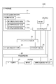
- FIG. 1 is a diagram illustrating an overall configuration of a diesel engine 1 including a regeneration control device 2 that controls regeneration of an exhaust gas treatment device 3 according to an embodiment of the present invention.
- FIG. 2 is a functional block diagram of the reproduction control apparatus 2 according to an embodiment of the present invention.
- the exhaust gas treatment device 3 has a DOC 31 and a DPF 32, and the regeneration control device 2 performs regeneration (recovery) of the exhaust gas treatment device 3 disposed in the exhaust passage 16 of the diesel engine 1. 3 is executed by controlling the temperature raising means 4 (described later).
- the diesel engine 1 mainly includes an engine main body 11, an intake passage 13, and an exhaust passage in addition to the regeneration control device 2 and the exhaust gas treatment device 3 described above. 16, an exhaust turbocharger 7, an EGR device 8, and an ECU 9.
- the intake passage 13 is a passage for supplying air (intake air) outside the engine 1 to the combustion chamber 12 formed in the engine body 11.
- the exhaust passage 16 is a passage for discharging the combustion gas (exhaust gas) from the combustion chamber 12 to the outside of the engine 1.
- the engine 1 is also provided with a fuel injection device 41 for injecting high-pressure fuel into the combustion chamber 12.
- the fuel injection device 41 is connected to a common rail (not shown) in which high-pressure fuel is accumulated, and its injection timing and fuel injection amount are controlled by an ECU 9 described later.
- the high pressure fuel injected into the combustion chamber 12 is mixed with the intake air supplied through the intake passage 13, burned in the combustion chamber 12, and discharged to the outside of the engine 1 through the exhaust passage 16.
- an exhaust turbocharger 7 is provided in the intake passage 13 and the exhaust passage 16.
- This exhaust turbocharger 7 has an exhaust turbine 71 disposed in the exhaust passage 16 and a compressor 72 disposed in the intake passage 13.
- the exhaust turbine 71 and the compressor 72 are connected by a shaft 73. Coaxially connected.
- the compressor 72 that is coaxially coupled by the shaft 73 is also rotationally driven in the same manner.
- the intake passage 13 is provided with an intercooler (not shown) and a throttle valve 42.
- the compressed intake air discharged from the compressor 72 is cooled by an intercooler (not shown), the intake flow rate is controlled by the throttle valve 42, and then provided to the main body of the engine 1 (not shown). It flows into the combustion chamber 12 in each cylinder of the engine 1 through the intake port 14.
- the opening degree of the throttle valve 42 is also controlled by the ECU 9 described later.
- the engine 1 includes an EGR device 8. That is, the intake passage 13 and the exhaust passage 16 are connected via the EGR pipe 81 so that a part of the exhaust gas flowing through the exhaust passage 16 can be recirculated to the intake passage 13.
- one end of the EGR pipe 81 is connected to a position immediately downstream of the exhaust port 17, and the EGR pipe 81 branches from the exhaust passage 16.
- the other end of the EGR pipe 81 is connected to the intake manifold 15 (intake passage 13) located on the downstream side of the throttle valve 42.
- an EGR valve 82 is disposed in the EGR pipe 81. By controlling the EGR valve 82, at least part of the exhaust gas discharged from the engine 1 is recirculated through the engine 1 through the EGR pipe 81. Note that the opening degree of the EGR valve 82 is also controlled by the ECU 9 described below.
- part of the exhaust gas discharged from the engine body 11 (combustion chamber 12) is recirculated to the intake passage 13 by the EGR device 8 under the control of the ECU 9.
- the exhaust gas remaining from the engine body 11 is configured to flow into the exhaust gas treatment device 3 provided in the exhaust passage 16 after driving the exhaust turbine 71 described above via the exhaust port 17.
- the exhaust gas treatment device 3 includes a DOC 31 (diesel oxidation catalyst) disposed in the exhaust passage 16 of the diesel engine 1 and a DPF 32 (diesel particulate filter) disposed in the exhaust passage 16 downstream of the DOC 31.
- the DOC 31 has a function of oxidizing and removing unburned fuel (HC) and carbon monoxide (CO) in the exhaust gas and oxidizing nitrogen monoxide (NO) in the exhaust gas to generate nitrogen dioxide (NO 2 ).
- HC unburned fuel
- CO carbon monoxide
- NO nitrogen monoxide
- Device Further, the temperature of the exhaust gas passing through the oxidation heat of the injected fuel is increased during the forced regeneration of the DPF 32, and the inlet temperature of the DPF 32 is increased.
- the DPF 32 is a device that collects PM (particulate matter) such as soot contained in the exhaust gas with a filter and removes it from the exhaust gas. That is, the exhaust gas flowing into the exhaust gas treatment device 3 passes through the DOC 31 and then passes through the DPF 32 inside the exhaust gas treatment device 3. During the passage, unburned fuel (HC) and carbon monoxide (CO) contained in the exhaust gas are oxidized and removed in the DOC 31. Moreover, PM contained in the exhaust gas is removed by collecting PM (particulate matter) in the exhaust gas by the DPF 32. After being treated by the exhaust gas treatment device 3 in this manner, the exhaust gas is discharged outside the engine 1.
- PM partate matter
- the ECU 9 is an electronic control unit that controls the engine 1 such as fuel injection control, throttle valve 42 opening control, and EGR valve 82 opening control as described above.
- the ECU 9 may be configured as a microcomputer including a central processing unit (CPU) including a processor, a random access memory (RAM), a read only memory (ROM), and an I / O interface.
- CPU central processing unit
- RAM random access memory
- ROM read only memory
- I / O interface I / O interface
- various sensors are provided in the exhaust passage 16.
- the detection values of these various sensors are input to the regeneration control device 2 for monitoring the exhaust gas and the state of the exhaust gas treatment device 3 by the regeneration control device 2 described later.
- a DOC inlet temperature sensor 51 is provided at the inlet of the DOC 31, and the exhaust gas temperature flowing into the DOC 31 is detected.
- the exhaust passage 16 is connected to the temperature sensor 5 such as the DPF inlet temperature sensor 52 provided at the inlet of the DPF 32 (between the DOC 31 and the DPF 32), the DPF outlet temperature sensor 53 provided at the outlet of the DPF 32, or the inlet of the DPF 32.
- Pressure sensors 6 such as a DPF inlet pressure sensor 61 provided, a DPF outlet pressure sensor 62 provided at the outlet of the DPF 32, and a DPF differential pressure sensor 63 capable of detecting a differential pressure between the inlet and the outlet of the DPF 32 are provided.
- the temperature of the DOC 31 is detected based on the detection value of the DOC inlet temperature sensor 51
- the temperature of the DPF 32 is detected based on the detection value of the DPF inlet temperature sensor 52. Yes.
- the regeneration control device 2 according to an embodiment of the present invention is provided in a diesel engine 1 as shown in FIG. 1, for example, and recovers (blocks recovery) the DOC 31 arranged in the exhaust passage 16 of the diesel engine 1.
- Process Rc) and forced regeneration (forced regeneration process Rf) of the DPF 32 disposed in the exhaust passage 16 downstream of the DOC 31 are executed.
- the regeneration control device 2 is an ECU 9 and is implemented as one of the functions (program or circuit) provided in the ECU 9.
- the regeneration control device 2 may be configured as another electronic control unit including a processor, in addition to the ECU 9 that controls the engine 1.
- the forced regeneration process Rf is classified into at least two types from the viewpoint of the trigger for starting the execution. That is, there are at least two types of automatic regeneration that is automatically performed and manual regeneration that is performed by a manual operation by an operator or the like.
- the automatic regeneration of the DPF 32 is automatically executed by satisfying a predetermined forced regeneration execution condition (automatic regeneration execution condition) related to automatic regeneration regardless of whether the vehicle is running or stopped.
- This automatic regeneration execution condition is, for example, when the estimated value of the PM accumulation amount in the DPF 32 exceeds a specified value (threshold), or when the operating time of the engine 1 exceeds a specified time (threshold), the cumulative fuel injection amount of the engine 1 When the value exceeds a specified amount (threshold value), etc. are mentioned.
- the PM accumulation amount in the DPF 32 can be estimated by detecting the differential pressure between the upstream and downstream of the DPF 32 by the DPF differential pressure sensor 63, for example.
- the engine speed, the fuel injection amount, the air flow rate, the DPF temperature are detected, and from the engine 1 based on the map stored in advance in the regeneration control device 2 It is also possible to estimate the amount of accumulated PM and the amount of PM regeneration due to natural regeneration inside the DPF 32 and subtract the amount of PM regeneration from the amount of PM discharged.
- the manual regeneration of the DPF 32 is executed as a forced regeneration execution condition (manual regeneration execution condition) that a button operation by an operator or the like is performed, and is basically performed with the vehicle stopped.
- This manual regeneration execution condition is executed when PM is accumulated exceeding the automatic regeneration condition.
- the manual regeneration may include combustion removal performed by a service person who performs maintenance when PM accumulates excessively on the DPF 32 (DPF recovery regeneration). In this case (DPF recovery regeneration), forced regeneration is performed over a longer time than normal manual regeneration in order to avoid overheating of the DPF 32. Also, there is a difference between the forced regeneration execution temperatures, and the manual regeneration is controlled to be higher than the automatic regeneration.
- the inlet temperature of the DPF 32 is controlled to be 600 to 610 ° C.
- the inlet temperature of the DPF 32 is controlled to be 620 to 630 ° C.
- the first temperature T1 (for example, 400 ° C.) is lower than the second temperature T2 (for example, 600 ° C. or more).
- the regeneration control device 2 performs the blockage recovery process Rc on the DOC 31 to burn and remove the deposits that block the DOC 31, thereby recovering the DOC 31. Further, by executing the forced regeneration process Rf on the DPF 32, the PM collected by the DPF 32 is burned and the DPF 32 is regenerated.
- the regeneration control device 2 includes a DOC blockage risk state determination unit 21, a DOC temperature increase execution unit 22, and a DPF forced regeneration. A condition determination unit 23, a DPF forced regeneration execution unit 24, and a counter reset processing unit 25 are provided.
- FIG. 3 is a diagram for explaining the forced regeneration process Rf of the DPF 32 executed by the early post injection and the late post injection according to the embodiment of the present invention.
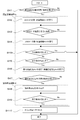
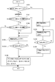
- FIG. 4 is a diagram showing the control logic of the reproduction recovery process R by the reproduction control apparatus 2 according to an embodiment of the present invention.
- FIG. 5 is a diagram illustrating the temperature transition of the DOC 31 and the DPF 32 corresponding to the control logic of the regeneration recovery process R in FIG.
- the regeneration recovery process R executed by the regeneration control apparatus 2 is a process for executing recovery of the DOC 31 and forced regeneration of the DPF 32.
- the DOC blockage risk state determination unit 21 determines whether or not the DOC31 is in the blockage risk state D1 in which the blockage of the DOC31 is likely to occur. judge.
- the DOC31 closing danger state D1 is a state in which the danger of the DOC31 being blocked is estimated based on the operating state of the engine 1, and the diesel engine 1 is in an operating state in which the DOC31 is likely to be blocked. This is the state detected when There are various methods for determining the DOC31 blockage risk state D1.
- the counter value C is the cumulative duration within a predetermined time immediately before the low exhaust temperature operation state in which the exhaust gas temperature discharged from the diesel engine 1 falls below the exhaust temperature threshold.
- the first counter value C1 is included.
- the DOC blockage risk state determination unit 21 determines that the DOC31 is in the blockage risk state D1 when the first counter value C1 exceeds the first threshold value V1.
- a state determination unit 21a is included.
- the exhaust temperature threshold is a threshold for determining the operating state of the engine 1 so that the blockage of the DOC 31 gradually proceeds based on the exhaust gas temperature, and when the low exhaust temperature operating state in which the exhaust gas temperature falls below the exhaust temperature threshold continues. DOC obstruction gradually proceeds.
- the DOC blockage is resolved. Therefore, according to the above configuration, it is possible to accurately determine the closing danger state D1 of the DOC 31 by determining the closing danger state D1 of the DOC 31 based on the cumulative duration time of the low exhaust temperature operation state within the latest predetermined time. it can. In addition, it is possible to prevent the DOC 31 from being blocked (closed state).
- the continuous duration time when the temperature of the exhaust gas is equal to or lower than a predetermined temperature is measured by the first counter value C1, and the first counter value
- first threshold value V1 the first threshold value
- the first counter value V1 the first counter value
- the average value of the estimated PM emission amount is a predetermined threshold value.
- first threshold value V1 When the continuous duration time in which the above states are continued is measured by the first counter value C1, and any one of the cases where the first counter value C1 has continued for a predetermined time (first threshold value V1) is applicable.
- DOC31 it may be determined that there is in the closed danger state D1. Furthermore, in some other embodiments, it may be determined that the DOC 31 is in the blockage risk state D1 when one or more of the determination methods described above are met.
- the counter value C includes a second counter value C2 and a third counter value C3, which are cumulative operation times of the diesel engine 1, as will be described later.
- the DOC blockage risk state determination unit in addition to the first blockage risk state determination unit 21a, sets the DOC31 in the blockage risk state when the second counter value C2 exceeds the second threshold value V2.
- a second blockage risk state determination unit 21b that determines that it is in D1 and a third blockage risk state determination unit 21c that determines that the DOC 31 is in the blockage risk state D1 when the third counter value C3 exceeds the third threshold value V3. Is included. That is, the regeneration control device 2 of the embodiment shown in FIG.
- the counter value C may include at least one of the first counter value C1, the second counter value C2, and the third counter value C3, of which at least The determination as to whether or not the DOC 31 is in the closing danger state D1 may be executed using one counter value.
- the DOC temperature increase execution unit 22 executes a blockage recovery process Rc (DOC blockage recovery regeneration) for heating the DOC31 to the first temperature T1.
- Rc DOC blockage recovery regeneration
- the DOC temperature increase execution unit 22 is connected to the DOC blockage risk state determination unit 21, and the determination result by the DOC blockage risk state determination unit 21 is input to the DOC temperature increase execution unit 22.
- the first temperature T1 is preferably around 400 ° C.
- the first temperature T1 may be a temperature within a range of 380 degrees Celsius (° C.) to 480 degrees Celsius (° C.).
- the temperature range of the first temperature T1 is a temperature set by newly finding that the deposit on the upstream end face of the DOC31 is burned by raising the temperature of the DOC31 to the first temperature T1. It becomes.
- the regeneration control device 2 performs the blockage recovery process Rc according to the blockage recovery process execution condition Pc including the target temperature increase temperature Pct and the temperature increase execution time Pcp set to the first temperature T1. Is configured to run.
- the DOC temperature increase execution unit 22 may forcibly complete the blockage recovery process Rc being executed by interruption, for example, when an interruption condition as described later is satisfied.
- the regeneration control device 2 executes retry control so that the clogging recovery process Rc is executed again after a predetermined time (retry time) e.g. after a few minutes. You may do it.
- the occlusion recovery process Rc may be executed from the beginning according to the occlusion recovery process execution condition Pc, or a time set for the purpose of placing the DOC 31 at the first temperature T1 for a predetermined time in the occlusion recovery process Rc ( The block recovery process Rc may be executed so that both the interrupted block recovery process Rc and the block recovery process Rc executed by the retry control are satisfied at time t3 to time t4 in FIG. Alternatively, when the above interruption is performed at a predetermined number of times of 1 or more, the DOC 21 is raised to a temperature higher than the predetermined number of interruptions or the automatic closing recovery process Rc executed by the regeneration control device 2.
- the regeneration control device 2 may notify the notification unit 28 (second notification unit 28b) so as to prompt the operator to execute the manual occlusion recovery process Rc for heating.
- This manual occlusion recovery process Rc is executed, for example, when an operator performs an operation such as pressing a manual regeneration button.
- the regeneration control device 2 performs the forced regeneration process Rf when the execution condition of the forced regeneration process Rf is satisfied when the closure recovery process Rc is interrupted (forced completion). You may perform (refer step S47 of FIG. 4).
- the temperature increase execution time Pcp may be an execution time from the start to the completion of the blockage recovery process Rc (time t2 to time t4 in FIG. 5).
- the clogging recovery process Rc controls the temperature raising means 4 (described later) to raise the temperature of the DOC 31 to the activation temperature T0 (for example, 250 ° C.) at which the DOC 31 is activated.
- the temperature increasing process Rc2 is included, and the first temperature increasing process Rc1 and the second temperature increasing process Rc2 are executed in this order.
- the occlusion recovery processing Rc is not limited to the above method.
- the temperature raising means 4 (described later) is controlled so as to raise the temperature of the DOC 31 at a stroke from the start of the clogging recovery process Rc to the first temperature T1 by the second temperature raising process Rc2. good.
- the temperature raising means 4 used in the blockage recovery process Rc includes a fuel injection device 41 that injects fuel into the combustion chamber 12 of the diesel engine 1.
- the first temperature raising process Rc1 and the second temperature raising process Rc2 are executed by early post injection by the fuel injection device 41.
- This early post-injection is the first post-injection that injects a smaller amount of fuel than the main injection in a state where the pressure in the combustion chamber 12 immediately after the main fuel is injected is still high in the step of injecting fuel into the engine 1. (See FIG. 3).
- the exhaust gas temperature can be raised without affecting the output of the diesel engine 1.
- the first temperature raising process Rc1 and the second temperature raising process Rc2 have different fuel injection conditions in early post injection, and the injection conditions of the first temperature raising process Rc1 are the same as the injection conditions of the second temperature raising process Rc2.
- the DOC 31 that has been heated to the activation temperature T0 is further heated to the first temperature T1.
- the second temperature raising process Rc2 has a larger fuel injection amount than the first temperature raising process Rc1, the injection timings of the first temperature raising process Rc1 and the second temperature raising process Rc2 are different, or
- the second temperature raising process Rc2 has a larger fuel injection amount than the first temperature raising process Rc1, and the injection timings of the first temperature raising process Rc1 and the second temperature raising process Rc2 are different.
- the first temperature raising process Rc1 and the second temperature raising process Rc2 have different injection conditions in at least one of the fuel injection amount or the injection timing.
- the first temperature raising process Rc1 may be executed by using the throttle valve 42 as the temperature raising means 4 and controlling the opening thereof.
- the common rail pressure control means (not shown) for controlling the common rail pressure for injecting fuel may be used as the temperature raising means 4 to control the common rail pressure.
- Two or more of the fuel injection device 41, the throttle valve 42, and the common rail pressure control means may be executed as the temperature raising means.
- the DOC temperature increase execution unit 22 is also used when the function unit (not shown) included in the regeneration control device 2 determines the closed state D2 in which the DOC 31 is closed to the extent that the recovery process (blocking recovery process Rc) is necessary.
- the occlusion recovery process Rc may be executed.
- the blocking state D2 of the DOC 31 can be detected based on a comparison between a blocking parameter P related to blocking of the DOC 31 and a predetermined blocking threshold.
- the closing parameter P may be the outlet temperature of the DPF 32, the outlet temperature of the DOC 31 (detected value of the DPF inlet temperature sensor 52), or the differential pressure between the inlet and outlet of the DOC 31.
- the DPF forced regeneration condition determination unit 23 determines whether or not the forced regeneration execution condition Pf of the DPF 32 is satisfied.
- the forced regeneration execution condition Pf is a case where the estimated value of the PM accumulation amount in the DPF 32 exceeds a specified value (threshold value).
- the pressure difference between the upstream and downstream of the DPF 32 is detected by the DPF differential pressure sensor 63, and the PM accumulation amount is estimated using a map that defines the relationship between the differential pressure across the DPF 32 and the PM accumulation amount. You may do it.
- the engine speed, the fuel injection amount, the air flow rate, the DPF temperature (for example, the detection value of the DPF outlet temperature sensor 53, etc.) are detected, and from the engine 1 based on the map stored in advance in the regeneration control device 2
- the PM emission amount and the PM regeneration amount by natural regeneration inside the DPF 32 may be estimated, and the PM accumulation amount may be estimated by subtracting the PM regeneration amount from the PM emission amount.
- the forced regeneration execution flag F is turned on when it is determined that the forced regeneration execution condition Pf is satisfied, and the forced regeneration execution flag F is turned off when the forced regeneration is completed.
- the forced regeneration execution flag F is a storage configured such as a nonvolatile memory such as a ROM or a flash memory provided in the regeneration control device 2, a volatile memory such as a RAM, or an external storage device connected to the regeneration control device 2. (Not shown).
- the DPF forced regeneration condition determination unit 23 may turn on the forced regeneration execution flag F, and the DPF forced regeneration execution unit 24 and the like may turn off the forced regeneration execution flag F after completion of the forced regeneration process Rf.
- the DPF forced regeneration execution unit 24 raises the DPF 32 to the second temperature T2 and executes the forced regeneration process Rf for raising the DOC 31 to the first temperature T1. To do.
- the DPF forced regeneration execution unit 24 executes the block recovery process Rc when the forced regeneration execution condition Pf is satisfied, and after the completion of the block recovery process Rc, the DPF 32 The temperature is raised to the second temperature T2. That is, when the forced regeneration execution condition Pf of the DPF 32 is satisfied and the forced regeneration process Rf is executed, the forced regeneration process Rf is executed after the DOC31 recovery process Rc is performed and the DOC31 is recovered. . As shown in FIG.
- the DPF forced regeneration execution unit 24 is connected to the DPF forced regeneration condition determination unit 23, and the determination result by the DPF forced regeneration condition determination unit 23 is input.
- the DPF forced regeneration execution unit 24 and the DOC temperature increase execution unit 22 are connected.
- the blocking recovery process Rc. Is executed to the DOC temperature increase execution unit 22, and after the completion notification of the closure recovery process Rc is obtained from the DOC temperature increase execution unit 22, the forced regeneration process Rf is executed.
- the present invention is not limited to the above-described embodiment, and in some other embodiments, the blockage recovery processing Rc is performed when the blockage danger state D1 of the DOC 31 is not detected and the forced regeneration execution condition Pf is satisfied.
- the forced regeneration process Rf may be executed independently.
- the DPF forced regeneration executing unit 24 raises the DPF 32 to a temperature at which the DOC 31 is activated (activation temperature T0) such as 250 ° C.
- the forced regeneration process Rf may be executed later.
- the forced regeneration process Rf is executed by using the temperature raising means 4 including the fuel injection device 41 that injects the fuel into the combustion chamber 12 of the diesel engine 1.
- the forced regeneration process Rf is executed by early post injection by the fuel injection device 41 and late post injection by the fuel injection device 41.
- the late post injection is a second post injection in which fuel is injected at a timing (near bottom dead center) that does not contribute to the combustion in the combustion chamber 12 after the early post injection. is there.
- a timing near bottom dead center
- the main fuel injection is performed after the top dead center, and then the early post Injection has been made. Then, late post injection is performed after the early post injection and before the piston reaches the bottom dead center (BDC) from the top dead center (TDC) side.
- the DPF 32 is heated to the second temperature T2.
- the PM deposited on the DPF 32 can be combusted by raising the temperature of the DPF 32 to the second temperature T2.
- the DPF forced regeneration execution unit 24 ends the late post injection when the PM accumulation amount becomes equal to or less than a threshold value for a predetermined time or longer, and performs the forced regeneration process Rf. It is supposed to be completed.
- the forced regeneration process Rf is performed by the exhaust pipe injection by the exhaust pipe injection device 44 disposed in the exhaust passage 16 upstream of the DOC 31 instead of or in combination with the late post injection. It may be executed using In the illustration of FIG. 1, the exhaust pipe injection device 44 is disposed between the branch position downstream of the EGR pipe 81 and the exhaust turbine 71 of the exhaust turbocharger 7. In some other embodiments, the exhaust pipe injector 44 may be between the exhaust turbine 71 and the DOC 31. Further, the fuel injection amount injected from the exhaust pipe injection device 44 into the exhaust passage 16 is controlled by the regeneration control device 2.
- the counter reset processing unit 25 resets the counter value C after the forced regeneration processing Rf by the DPF forced regeneration executing unit 24 is completed. That is, it is included in the counter value C related to the operation time of the diesel engine 1, such as the above-mentioned first counter value C1 for monitoring the DOC31 closing danger state D1, the second counter value C2 and the third counter value C3 described later. All counter values are reset.
- the reset here is not limited to setting the initial value of the counter (for example, 0), but is a value that reflects the degree of adhesion of the DOC 31 adhering when the forced regeneration process Rf is completed. It also includes subtracting the counter value. In the embodiment shown in FIGS. 1 to 5, as shown in FIG.
- the counter reset processing unit 25 is connected to the DOC temperature increase execution unit 22 and the DPF forced regeneration execution unit 24, respectively.
- a completion notification is input from the DOC temperature increase execution unit 22
- the forced regeneration process Rf is executed alone, or when the closure recovery process Rc and the forced regeneration process Rf are performed. Is executed, the completion notification is input from the DPF forced regeneration execution unit 24.
- the counter reset processing unit 25 resets all of the first counter value C1, the second counter value C2, the third counter value C3, and the like included in the counter value C.
- the counter value that is actually counted up for the determination of the blockage danger state D1 included in the counter value C may be reset.
- regeneration control apparatus 2 is monitoring periodically, for example whether the execution conditions of the reproduction
- the execution condition of the regeneration recovery process R is a condition that the DOC 31 exists in the temperature rise required state D including the blockage dangerous state D1, and a condition that the forced regeneration execution condition Pf is satisfied (whether the forced regeneration execution flag F is on). Including. If any of the execution conditions of the regeneration recovery process R is satisfied, the process proceeds to the next step S42, and the first temperature increase process Rc1 of the DOC 31 is executed.
- the forced regeneration execution condition Pf is determined to satisfy the automatic regeneration execution condition of the DPF 32, the manual regeneration execution condition, or at least one of the automatic regeneration execution condition and the manual regeneration execution condition. It may be a case of satisfying.
- the regeneration control device 2 turns on the forced regeneration execution flag F.
- the control logic of the reproduction recovery process R in FIG. 4 is terminated.
- the temperature rise requirement state D may include a closed state D2.
- the first temperature increase process Rc1 is started from time t1 when the execution condition is satisfied. For this reason, the rising speed of the temperature of DOC31 changes in the direction which increases in the time t1, and the temperature rise of DOC31 by 1st temperature rising process Rc1 is started.
- step S43 in FIG. 4 the regeneration control device 2 monitors whether the DOC 31 has reached the activation temperature T0 by the first temperature raising process Rc1.
- the regeneration control device 2 completes the first temperature raising process Rc1, and then executes the second temperature raising process Rc2 in step S44.
- the first temperature raising process Rc1 is completed at time t2.
- the second temperature raising process Rc2 is started at time t2. For this reason, the rising speed of the temperature of DOC31 is changing in the direction which increases in the time t2. Further, the temperature of the DOC 31 further increases from the activation temperature T0 at the time t2, and the temperature of the DOC 31 reaches the first temperature T1 at the time t3.
- step S45h in FIG. 4 the regeneration control device 2 monitors whether or not the interruption condition of the second temperature raising process Rc2 is satisfied, and in step S45 in FIG. After the start of the process Rc2, it is monitored whether the completion condition of the second temperature raising process Rc2 is satisfied.
- the completion condition of the second temperature raising process Rc2 is set for the purpose of keeping the DOC 31 for a predetermined time at a temperature at which the deposit of the DOC 31 burns (first temperature T1).
- the occlusion recovery process Rc reaches the first temperature T1 after the elapse of a predetermined time from the start of the second temperature increase process Rc2 or after the start of the second temperature increase process Rc2.
- the predetermined time may be, for example, 20 minutes or more after reaching the first temperature T1. Further, the time may be set according to the amount of deposits of DOC 31 to be removed by the clogging recovery process Rc (such as a map). As a result, the DOC 31 can be kept for a predetermined time at the first temperature T1 at which the deposits of the DOC 31 can be combusted, and the DOC 31 can be regenerated from the temperature rise required state D including the blockage dangerous state D1.
- the second temperature raising process Rc2 is completed at a predetermined time after reaching a temperature lower than the first temperature T1 by a predetermined temperature (for example, 10 degrees Celsius or less). You may comprise so that it may complete later. However, the predetermined time may be 0. For example, when the temperature reaches the first temperature T1, the completion condition of the second temperature raising process Rc2 may be satisfied.
- a predetermined temperature for example, 10 degrees Celsius or less.
- the interruption condition is for interrupting (forcibly completing) the clogging recovery process Rc even if the completion condition is not satisfied.
- the clogging recovery process Rc the first temperature raising process Rc1
- the interruption recovery process Rc is interrupted.
- Conditions may be set.
- a time that is equal to or longer than the time at which the DOC 31 is expected to reach the first temperature T1 from the start of the second temperature raising process Rc2 is set as a timeout time, and this time-out time has elapsed from the start of the second temperature raising process Rc2.
- the interruption condition may be set so as to interrupt the closing recovery process Rc.
- the control logic of the regeneration recovery process R ends.
- the above-described retry control may be executed from step S 42, or the manual block recovery process Rc may be executed. You may alert
- the control logic of the reproduction recovery process R may be continued by jumping from step S45h to step S46 or step S47 described later.
- the DOC temperature increase execution unit 22 is connected to a temperature increase temperature monitoring unit 26 (described later) so that the temperature of the DOC 31 can be acquired. It has become.
- step S45 when the completion condition for the second temperature raising process Rc2 is satisfied, the regeneration control device 2 completes the second temperature raising process Rc2 in step S46, and the clogging recovery process Rc is completed.
- the condition for completing the second temperature raising process Rc2 is satisfied at time t4.
- step S47 of FIG. 4 the regeneration control device 2 determines whether or not the execution condition of the forced regeneration process Rf is satisfied. If the execution condition of the forced regeneration process Rf is satisfied, step S48 and subsequent steps are executed. It is determined that the execution condition of the forced regeneration process Rf is satisfied when the forced regeneration execution flag F is determined to be on in step S41 or when the forced regeneration execution flag F is off in step S41. This includes the case where the forced regeneration execution flag F is determined to be on at the time of the determination in step S47, such as when the forced regeneration execution flag F is turned on during execution of the blocking recovery process Rc (steps S42 to S46).
- step S47 the process proceeds to step S410 without executing the forced regeneration process Rf.
- the execution condition of the forced regeneration process Rf is based on the determination that the execution condition in step S41 satisfies the forced regeneration execution condition Pf. This is a case where the first counter value C1 exceeds the first threshold value V1 by the first closing danger state determination unit 21a.
- step S48 the forced regeneration process Rf is executed.
- step S49 for example, when the completion condition of the forced regeneration process Rf such as after a predetermined time has elapsed, the forced regeneration process Rf is completed.
- the forced regeneration execution flag F is turned off (not shown).
- the forced regeneration process Rf is executed from the time when the DOC 31 and the DPF 32 are heated to the vicinity of the first temperature T1 at time t4, and the forced regeneration process Rf performs the time t5.
- the DPF 32 is heated up to the second temperature T2.
- the temperature raising means 4 is controlled by the regeneration control device 2 so as to maintain the second temperature T2.
- the temperature raising means 4 is controlled by the regeneration control device 2 so as to maintain the first temperature T ⁇ b> 1 as it is from the time t ⁇ b> 4 when the closing recovery process Rc is completed.
- the recovery of the DOC 31 is performed during the execution of the forced regeneration process Rf as in the execution of the block recovery process Rc, and the recovery of the DOC 31 in the temperature increase required state D is forced to be performed together with the block recovery process Rc. This is performed by the reproduction process Rf.
- the forced regeneration process Rf is completed, and after time t6, the temperature of the DOC 31 and the temperature of the DPF 32 are gradually decreased with time.
- the temperature of the DOC 31 is controlled to maintain the first temperature T1 as shown in FIG. 5, but in some other embodiments, Alternatively, the activation temperature T0 may be controlled to be maintained.
- the forced regeneration process Rf is interrupted when the interruption condition is satisfied.
- a step may be provided between step S48 and step S49. If this interruption condition is satisfied, the flow of FIG. 4 is terminated after or without executing step S410 even if the completion condition of the forced regeneration process Rf in step S49 is not satisfied.
- the forced regeneration process Rf is interrupted, for example, when the exhaust gas temperature at the outlet of the DPF 32 (for example, the detected value of the DPF outlet temperature sensor 53) is larger than the second temperature T2 during the forced regeneration process Rf of the DPF 32.
- a case where a predetermined temperature threshold value (for example, 750 ° C. or higher) is exceeded may be regarded as a DPF abnormal high temperature error and whether or not a DPF abnormal high temperature error is detected.
- a predetermined temperature threshold value for example, 750 ° C. or higher
- the forced regeneration process Rf may be interrupted to prevent the DPF 32 from being burned out, and it may be determined that the DOC 31 is in the temperature rise required state D, and the blockage recovery process Rc from step S42 may be executed again.
- the temperature increase execution time Pcp (described later) may be longer than that when no abnormal high temperature error is detected, and the longer clogging recovery process Rc time By securing (specifically, the time between time t3 and time t4 in FIG. 5), it is possible to reliably recover the blockage of the DOC 31.
- step S410 the reproduction control device 2 resets all counter values C including the first counter value C1 and the like.
- step S410 is executed regardless of whether or not the forced regeneration process Rf in step S48 is executed. This is because, regardless of whether or not the execution condition of the forced regeneration process Rf is satisfied in step S47, the closure recovery process Rc has already been executed in steps S42 to S46, and the DOC 31 is recovered by the closure recovery process Rc. It is to do. Then, after step S410, the control logic of the reproduction recovery process R is terminated.
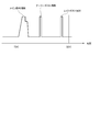
- FIG. 6A is a diagram showing a time chart of the reproduction recovery process R executed by the control logic of the reproduction recovery process R in FIG.
- FIG. 6B is a comparative example shown for comparison with FIG. 6A in the case where the counter value C is not reset after completion of the forced regeneration processing Rf.
- the DPF 32 satisfies the forced regeneration execution condition Pf, for example, every time interval of about 10 hours to 20 hours (every 20 hours in FIGS. 6A to 6B).
- the regeneration control device 2 executes a regeneration recovery process R (first regeneration recovery process R1) including a block recovery process Rc and a forced regeneration process Rf.
- the DOC 31 is determined to be in the blockage dangerous state D1 (temperature increase required state D) by the first blockage dangerous state determination unit 21a every 10 hours or more (every 13 hours in FIGS. 6A to 6B).
- the regeneration control device 2 executes a regeneration recovery process R (second-type regeneration recovery process R2) consisting of a blockage recovery process Rc.
- the execution time of the reproduction recovery process R is not considered and is included in the above-described time interval.
- the execution start of the first regeneration recovery process R (R1) shown in the figure is used as a reference (time 0), and the forced regeneration execution condition Pf is satisfied to satisfy the block recovery process Rc and the forced regeneration process Rf.
- the first type regeneration recovery process R1 is executed three times every 20 hours.
- the counter value C is reset every time the first type reproduction recovery process R1 is completed.
- the second type regeneration recovery process R2 executed at intervals of 13 hours when the first obstruction risk state determination unit 21a determines the obstruction risk state D1 is the above-described three first type regeneration recovery processes R1. It is executed every 13 hours from each of the executions. For this reason, in FIG. 6A, the total number of blockage recovery processes Rc executed by the first type regeneration recovery process R1 and the second type regeneration recovery process R2 is five.
- FIG. 6B is a diagram (comparative example) in which the counter value C is not reset after completion of the forced regeneration process Rf, and the counter value C is reset after completion of the first type regeneration recovery process R1. Instead, it is reset only after the completion of the second type regeneration recovery process R2. That is, the second type reproduction recovery process R2 is executed every 13 hours regardless of the first type reproduction recovery process R1. For this reason, in FIG. 6B, the total number of times of the blocking recovery process Rc executed by the first type regeneration recovery process R1 and the second type regeneration recovery process R2 is six times, compared with five times in the case of FIG. 6A. Once more. Also, for example, in FIG.
- the time interval between the second type regeneration recovery process R2 executed after 39 hours and the third type regeneration recovery process R1 executed after 40 hours has elapsed is 1 hour.
- the DOC 31 is slightly smaller than 13 hours, which is the interval to reach the closing danger state D1.
- the amount of deposits adhering to the DOC 31 is small from the completion of the second type regeneration recovery process R2 executed at the 39th hour to the 40th hour, nevertheless, the first type regeneration at the 40th hour is nevertheless.
- the situation is such that the blockage recovery process Rc by the recovery process R1 is executed. In other words, in the example of FIG.
- the regeneration control device 2 adjusts the execution timing of the block recovery process Rc by resetting the counter value C as described above, and the first time between the execution intervals of the first regeneration recovery process R1.
- the execution frequency of the second type reproduction recovery process R2 is optimized by executing the type two reproduction recovery process R2.
- the determination as to whether or not the DOC 31 is in the blockage dangerous state D1 and the determination as to whether or not the forced regeneration execution condition Pf of the DPF 32 is satisfied are performed separately.
- the regeneration control device 2 determines that the DOC 31 is in the blockage risk state D1
- the regeneration control device 2 executes the blockage recovery processing Rc.
- the regeneration control device 2 determines that the forced regeneration execution condition Pf is satisfied
- the regeneration control device 2 executes the blockage recovery processing Rc and the forced regeneration processing Rf.
- the DOC32 blockage recovery process Rc is executed together with the DPF32 forced regeneration process Rf, so that the recovery of the DOC31 and the regeneration of the DPF32 can be performed efficiently.
- the DOC 31 is obstructed in advance, and when the DPF 32 is forcibly regenerated, the DOC 31 is first recovered to prevent the unburned fuel from slipping due to the DOC 31 being obstructed. Burnout and oil dilution can be prevented.
- the counter value C for determining whether or not the DOC 31 is in the closing danger state D1 is reset.
- the occlusion recovery process Rc can be executed at an appropriate frequency.
- the DPF forced regeneration execution unit 24 determines that the DOC 31 is in the DOC 31 in the blockage dangerous state D1 when the first blockage dangerous state determination unit 21a determines that the DOC31 is in the blockage dangerous state D1.
- the forced regeneration process Rf is executed after the blockage recovery process Rc by the temperature increase execution unit 22 is completed. That is, when the first blockage risk state determination unit 21a determines that the DOC 31 is in the blockage risk state D1, even if the forced regeneration execution condition Pf is not satisfied, the forced recovery execution condition Rf is also compulsory.
- the reproduction process Rf is executed.
- the blockage risk state D1 of the DOC 31 is determined based on the first counter value C1, and when the blockage recovery process Rc is executed based on the determination based on the first counter value C1, the forced regeneration process Rf of the DPF 32 is also executed. . For this reason, recovery of DOC32 and regeneration of DPF31 can be performed efficiently. In addition, since the forced regeneration process Rf can be executed from the point where the temperature has been raised to the first temperature T1 by the closure recovery process Rc, the fuel efficiency can be improved.
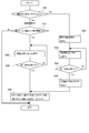
- FIG. 7 is a diagram showing the control logic of the regeneration recovery process R of the regeneration control apparatus 2 according to one embodiment of the present invention, where the blockage recovery process Rc is executed based on the determination of the first blockage risk state determination unit 21a.
- the control logic of FIG. 7 is performed periodically, for example.
- the regeneration control device 2 determines whether or not the forced regeneration execution flag F is on during normal operation or the like. More specifically, it is determined whether or not the forced regeneration execution condition Pf of the DPF 32 including at least one of the automatic regeneration execution condition and the manual regeneration execution condition is satisfied.
- step S77 the regeneration control device 2 determines whether or not the DOC 31 is in the closing danger state D1 during the operation of the engine 1. The state is determined by the state determination unit 21a. If it is determined in step S77 that the DOC 31 is not in the closing danger state D1, the control logic of FIG. 7 is terminated. Conversely, if it is determined in step S71 that the forced regeneration execution condition Pf is satisfied, or if it is determined in step S76 that the DOC 31 is in the closing danger state D1, the regeneration control device 2 executes the regeneration recovery process R. . Specifically, the obstruction recovery process Rc is executed in step S72, and then the forced regeneration process Rf is executed in step S73.
- step S74 When the forced regeneration process Rf is completed in step S74, the forced regeneration execution flag F is turned off in step S75, and the process proceeds to step S76.
- step S76 all counter values C including the first counter value C1 are reset.
- steps S72 to S76 in FIG. 7 correspond to steps S42 to S410 in FIG. 4 already described, and the execution condition of the forced regeneration process Rf in step S47 in FIG. 4 is the forced regeneration execution condition Pf of the DPF 32. This corresponds to the case where Steps S42 to S410 in FIG. 4 are executed when either is satisfied or when either the DOC 31 is in the closing danger state D1.
- the regeneration control device 2 when the first closing danger state determination unit 21a determines that the DOC 31 is in the closing danger state D1, the regeneration control device 2 continues the forced regeneration process after the completion of the obstruction recovery process Rc. Rf is executed.
- the forced regeneration process Rf can be executed from the point where the temperature has been raised to the first temperature T1 by the closure recovery process Rc, so that the fuel consumption can be improved.
- the DOC blockage risk state determination unit 21 determines at least one of the exhaust temperature threshold value or the first threshold value V1 based on at least one of atmospheric pressure, atmospheric temperature, and water temperature of the diesel engine. And a determination threshold value correction unit 21u that corrects the error. That is, the exhaust temperature threshold value and the first threshold value used for the determination by the first obstruction risk state determination unit 21 a are corrected according to the environment around the engine 1. For example, in an environment such as a high altitude where the atmospheric pressure is low and the oxygen concentration in the atmosphere is low, the DOC 31 is more likely to be clogged than in an environment where it is not. For this reason, the exhaust temperature threshold value and the first threshold value V1 set in the assumed environment are corrected when the DOC 31 is more likely to be blocked than in the assumed environment, thereby preventing the DOC 31 from being blocked.
- the determination threshold correction unit 21u indicates that the engine 1 is placed in an environment in which the DOC 31 is more likely to be blocked.
- the regeneration control device 2 determines that the ambient pressure and atmospheric temperature around the engine 1 Judge based on the water temperature.
- the determination threshold value correction unit 21u corrects the exhaust temperature threshold value to a larger value, or the first threshold value V1. Is made smaller.
- the occlusion recovery process Rc executed by the determination by the first obstruction risk state determination unit 21a after the correction is executed at an earlier timing than before the correction.
- the determination threshold value correction unit 21u calculates a correction coefficient for correcting at least one of the exhaust temperature threshold value and the first threshold value V1, and calculates the correction coefficient by at least one of the exhaust temperature threshold value and the first threshold value V1.
- the corrected exhaust temperature threshold or the first threshold V1 may be determined.
- This correction coefficient may be acquired using a map or a function that defines a correspondence relationship between the correction coefficient and at least one of the atmospheric pressure, the atmospheric temperature, and the water temperature of the engine 1. With this map, a correction coefficient can be easily obtained from at least one of atmospheric pressure, atmospheric temperature, water temperature of the engine 1 and the like, and at least one of the exhaust temperature threshold value or the first threshold value V1 is automatically or manually corrected. be able to.
- the determination threshold value correction unit 21u determines at least one of the second threshold value V2 and the third threshold value V3. It may be corrected. Since the description in this case is described by replacing the first threshold value V1 in the description regarding the determination threshold value correction unit 21u with the second threshold value V2 and the third threshold value V3, the description is omitted.
- the regeneration control device 2 further includes a temperature rising temperature monitoring unit 26 that monitors the temperature T of the DOC 31 during the execution of the closing recovery process Rc, and this actual temperature T of the DOC 31.
- a temperature rising temperature monitoring unit 26 that monitors the temperature T of the DOC 31 during the execution of the closing recovery process Rc, and this actual temperature T of the DOC 31.
- An embodiment for controlling the occlusion recovery processing Rc will be described based on FIG.
- the temperature rise monitoring unit 26 is connected to the DOC inlet temperature sensor 51, and the temperature detected by the DOC inlet temperature sensor 51 is input, so that the temperature of the DOC 31 is increased. Acquisition and monitoring are possible.
- the counter value C includes a second counter value C2 that is the cumulative operation time of the diesel engine 1, and the DOC blockage risk state determination unit 21 determines that the second counter value C2 is a predetermined second threshold value V2.
- the second blockage risk state determination unit 21b that determines that the DOC 31 is in the blockage risk state D1 when the value exceeds the upper limit is further included.
- the regeneration control device further defines a time during which the temperature T of the DOC 31 exceeds the first temperature threshold value lower than the first temperature T1 during the execution of the blockage recovery process Rc determined by the first blockage risk state determination unit 21a.
- the second blockage risk state determination unit 21b starts to determine the blockage risk state D1.
- a mode activation unit 27 that activates the recovery mode when the temperature rise is poor is provided.
- the specified time of the present embodiment is determined as the time required for recovering the DOC 31 in the closed block dangerous state D1 in the state where the temperature is raised to the first temperature T1.
- the temperature T of the DOC 31 is monitored in each of the clogging recovery processing Rc executed at least once according to the operation time of the engine 1, and based on the temperature T of the DOC 31 for each clogging recovery processing Rc, It is determined whether or not the DOC 31 has been properly recovered by each blockage recovery process Rc, and the recovery mode at the time of a temperature increase failure is activated according to the determination result.
- This recovery mode at the time of temperature increase failure is a mode for executing the closing recovery process Rc at a timing earlier than the closing recovery process Rc executed by the determination of the first closing danger state determination unit 21a.
- the regeneration control device 2 increases the frequency of the blockage recovery process Rc by starting the recovery mode at the time of the temperature increase failure so that the recovery of the DOC 31 whose recovery is insufficient due to the blockage recovery process Rc of the temperature increase failure is ensured.
- the mode activation unit 27 is configured to stop the determination of the blockage risk state D1 by the first blockage risk state determination unit 21a and start the determination by the second blockage risk state determination unit 21b. ing.
- the determination by the first obstruction risk state determination unit 21a and the determination by the second obstruction risk state determination unit 21b may be performed simultaneously.
- the first temperature threshold is, for example, 360 degrees Celsius (° C.)
- the first number is, for example, two times
- the specified time is 15 minutes.
- the present invention is not limited to this embodiment, and the first temperature threshold may be lower than the first temperature T1, and the first number may be 1 or more.
- the first number may be set to a number that can detect a temperature increase failure due to a temporary cause, such as when the first number is 2 times, recovery due to a temperature increase failure due to a temporary cause occurs. It is possible to prevent the mode from being frequently activated and to prevent the fuel consumption from being lowered.
- the temperature increase of the DOC 31 is appropriately performed in the occlusion recovery process Rc. If the temperature of the DOC 31 is not appropriately raised, the SOF content such as unburned fuel and soot adhering to the upstream end face of the DOC 31 are not sufficiently burned by the clogging recovery process Rc, and the DOC 31 is not properly recovered. . For this reason, when the blockage recovery process Rc of the temperature rise failure continues for the first number of times, the determination of the blockage risk state D1 by the second blockage risk state determination unit 21b is started to prevent the blockage of the DOC31. be able to.
- the second threshold value V2 is set to be greater than the average time interval between two consecutive blockage recovery processes Rc executed by the determination of the first blockage risk state determination unit 21a.
- the average time interval between two consecutive blockage recovery processes Rc executed by the determination of the blockage risk state determination unit 21b is set to be smaller.
- the second threshold value V2 used by the second blockage risk state determination unit 21b is, for example, 3 hours, and is set shorter than the first threshold value V1 that is, for example, 10 hours or more, whereby the first blockage risk state determination unit 21a.
- the second blockage risk state determination unit 21b determines the blockage risk state D1 earlier than the determination of the blockage risk state D1.
- the first occlusion recovery process Rc is executed after the completion of the preceding occlusion recovery process Rc and before the subsequent occlusion recovery process Rc is executed. 2.
- the blockage recovery process Rc is executed according to the determination of the blockage risk state determination unit 21b. For this reason, in the blockage recovery process Rc executed by the determination of the first blockage risk state determination unit 21a, the blockage recovery process Rc of the temperature rise failure where the DOC31 has not been heated appropriately for some reason occurs, and the DOC31 is set appropriately.
- the occlusion recovery processing Rc can be performed more frequently by executing the occlusion recovery processing Rc according to the determination of the second obstruction risk state determination unit 21b, and the DOC 31 can be appropriately used. Can be recovered.
- the mode activation unit 27 is configured when the temperature of the DOC 31 in the clogging recovery process Rc executed after the activation of the recovery mode at the time of the temperature increase exceeds the first temperature threshold. Then, the recovery mode when the temperature rise is poor is terminated. That is, even if the determination of the dangerous blockage state D1 by the second closed dangerous state determination unit 21b is once started, if the dangerous blockage state D1 that is not a poor temperature rise is executed, the second closed dangerous state determination unit 21b. The determination of the blockage risk state D1 by is ended.
- the recovery from the DOC 31 by the clogging recovery process Rc returns to the state in which the recovery is properly performed after the start-up of the recovery mode at the failure in temperature increase, the recovery mode at the failure in temperature increase is terminated.
- the occlusion recovery process Rc By returning the occlusion recovery process Rc to the normal frequency, it is possible to prevent a reduction in fuel consumption.
- the regeneration control device 2 determines that the clogging recovery process Rc due to a temperature rise failure has continued for a second number of times greater than the first number, or this A notification unit 28 (first notification unit 28a) for notifying that the execution of the manual occlusion recovery processing Rc is promoted by continuing the second number of times is further provided. That is, when the clogging recovery process Rc due to a temperature rise failure continues for the second number of times, it is highly likely that the clogging recovery process Rc due to a temperature rise failure has not occurred due to a temporary factor. It is configured to prompt a response by notifying.
- the notification unit 28 (first notification unit 28a, second notification unit 28b) is connected to a notification device (not shown) such as a display, a speaker, a light emitting device such as an LED or a lamp, or a vibration device, thereby providing a notification device ( You may alert
- the operator's notification may be a visual notification by display on a display, lighting by a light emitting device, flashing, etc., an auditory notification by sound or sound, or by vibration, and a combination thereof. May be.
- the first number is two and the second number is eight.
- the present invention is not limited to this embodiment, and the second number is determined to require notification to the operator. Any number of times may be used.
- the mode activation unit 27 may make the above determination and instruct the notification unit 28 to notify.
- the operator who has received the notification may respond by executing a manual occlusion recovery process Rc for raising the temperature of the DOC 21 to a temperature higher than the automatic occlusion recovery process Rc executed by the regeneration control device 2. .
- the counter value C includes a third counter value C3 that is the cumulative operation time of the diesel engine 1.
- the DOC blockage risk state determination unit 21 includes the third blockage risk state determination unit 21c that determines that the DOC31 is in the blockage risk state D1 when the third counter value C3 exceeds the third threshold value V3.
- the reset processing unit 25 resets the counter value C including the third counter value C3 after completion of the closing recovery process Rc started in response to the determination of the third closing danger state determining unit 21c.
- the third blockage danger state determination unit 21c is configured to cope with the case where the engine 1 is placed in an environment where the DOC 31 is likely to be blocked, and the PM composition (soot and soot) is changed by the environmental change in which the engine 1 is placed. SOF, etc.) and the combustion state are changed, and this is a configuration for dealing with a case where the closing speed of the DOC 31 increases. For example, the higher the altitude, the lower the oxygen concentration in the air, but when the oxygen concentration decreases, the combustion state of the engine 1 deteriorates, resulting in an increase in the closing speed of the DOC 31. When the closing speed of the DOC 31 increases in this way, the closing danger state D1 is determined based on the cumulative operation of the engine 1.
- the third threshold value V3 is set to 5 to 10 hours, and is set to be smaller than the first threshold value V1 such as 10 hours or more, for example, by the first obstruction risk state determination unit 21a. It may be set shorter than the average time interval at which the blockage risk state D1 is determined and longer than the second threshold value V2 used for determination by the second blockage risk state determination unit 21b. Thus, by increasing the execution frequency of the block recovery process Rc, the block of the DOC 31 placed in an environment in which blockage is likely to occur is prevented.
- the third threshold value V3 is based on a map or function that defines a correspondence relationship between at least one of the atmospheric pressure, the atmospheric temperature, the water temperature of the engine 1 and the third threshold value V3 that can estimate an environment in which blockage is likely to occur. It may be set automatically or manually.
- the third blockage dangerous state determination unit 21c determines that the DOC 31 is in an environment where the blockage of the DOC 31 is likely to occur, such as when the oxygen concentration in the atmosphere is lower than that in the assumed environment. Count.
- the blockage risk state D1 is respectively determined by the plurality of functional units (at least two of the first blockage risk state determination unit 21a, the second blockage risk state determination unit 21b, and the third blockage risk state determination unit 21c). By monitoring, it is possible to prevent the DOC 31 from being blocked.
- FIG. 8 is a diagram showing the control logic of the regeneration recovery process R of the regeneration control apparatus 2 according to one embodiment of the present invention, where the obstruction recovery process Rc is executed based on the determination of the third obstruction risk state determination unit 21c.
- the control logic of the reproduction recovery process R in FIG. 8 is performed periodically, for example.
- steps S81 to S86 are the same as S71 to S76 in FIG.
- step S87 of FIG. 8 during the operation of the engine 1, the regeneration control device 2 determines whether or not the DOC 31 is in the closing danger state D1 by the third closing danger state determination unit 21c. If it is determined in step S87 that the DOC 31 is not in the closing danger state D1, the control logic of FIG. 8 is terminated.
- step S87 when it is determined in step S87 that the third counter value C3 exceeds the third threshold value V3, it is determined that the DOC 31 is in the blockage risk state D1, and therefore the blockage recovery process is performed in step S88. Rc is executed. And after it determines with the obstruction
- FIG. 9 is a diagram showing the control logic of the regeneration recovery process R of the regeneration control device 2 according to one embodiment of the present invention, in which the determination of the first obstruction risk state determination unit 21a and the third obstruction risk state determination unit 21c. Based on the determination, the blockage recovery process Rc is executed.
- the control logic of FIG. 9 is performed periodically, for example.
- steps S91 to S97 are the same as S71 to S77 in FIG.
- step S97 of FIG. 9 when the regeneration control apparatus 2 determines whether or not the DOC 31 is in the closing danger state D1 during the operation of the engine 1, the DOC 31 is in the closing danger state D1. If it is determined that it is not, the process proceeds to step S98.
- step S98 the regeneration control apparatus 2 determines whether or not the DOC 31 is in the closing danger state D1 by the third closing danger state determination unit 21c. If it is determined in step S98 that the third counter value C3 exceeds the third threshold value V3, the blockage recovery process Rc is executed in step S99. Then, after it is determined in step S910 that the occlusion recovery process Rc is completed, the process proceeds to step S96, and all counter values C including the first counter value C1 and the third counter value C3 are reset. Conversely, if it is not determined in step S98 that the third counter value C3 exceeds the third threshold value V3, the control logic of FIG. 9 is terminated.
- FIG. 10 is a diagram showing the control logic of the regeneration recovery process R of the regeneration control device 2 according to one embodiment of the present invention, and the determination of the second obstruction risk state determination unit 21b and the third obstruction risk state determination unit 21c. Based on the determination, the occlusion recovery process Rc is executed.
- the control logic of FIG. 10 is performed periodically, for example. Steps S101 to S106 and Steps S109 to S1010 in FIG. 10 are the same as Steps S91 to S96 and Steps S99 to S910 in FIG.
- the regeneration control device 2 determines whether or not the DOC 31 is in the closing danger state D1 during the operation of the engine 1, whether the second closing danger state determination unit 21b or the third closing danger state determination unit.
- Each is determined by 21c. Specifically, when either the second counter value C2 exceeds the second threshold value V2 or the third counter value C3 exceeds the third threshold value V3, the process proceeds to step S109 and is blocked. The recovery process Rc is executed. Conversely, if it is not determined in both step S107 and step S107 that the second counter value C2 exceeds the second threshold value V2, and if the third counter value C3 is not determined to exceed the third threshold value V3, The control logic of FIG. 10 is terminated.
- the regeneration control device 2 executes the blockage recovery process Rc based on the accumulated operation time.
- the DOC 31 is likely to be blocked
- the regeneration control device 2 executes the blockage recovery process Rc based on the accumulated operation time.
- the regeneration control device 2 further performs the subsequent control based on the temperature of the DOC in the preceding block recovery process Rc in two consecutive block recovery processes Rc.
- a blockage recovery process condition correction unit 29 for correcting the temperature rise temperature or the temperature rise execution time in the blockage recovery process Rc.
- the DOC temperature increase execution unit 22 executes the block recovery process Rc in accordance with the block recovery process execution condition Pc
- the temperature T of the DOC 31 in the block recovery process Rc is the target temperature increase Pct (first temperature T1) due to some cause. A situation can occur that does not reach.
- the clogging recovery process condition correction unit 29 corrects the clogging recovery process execution condition Pc to include the remaining deposits that are not sufficiently burned by the previous clogging recovery process Rc to be executed next. By making it burn by the recovery process Rc, the DOC 31 is reliably recovered.
- the clogging recovery processing condition correction unit 29 is connected to the temperature rising temperature monitoring unit 26, and acquires information on the temperature T of the DOC 31 from the temperature rising temperature monitoring unit 26. Then, based on the temperature T of the DOC 31 in the first completed block recovery process Rc, the block recovery process execution condition Pc of the subsequent block recovery process Rc to be performed next is corrected (set). More specifically, the blockage recovery process execution condition Pc includes at least one of the target temperature increase temperature Pct or the temperature increase execution time Pcp, and the blockage recovery process condition correction unit 29 corrects at least one of these.
- the target temperature rise Pct is increased to correct the temperature so that the DOC 31 is heated to a higher temperature.
- the actual temperature T of the DOC 31 may be close to the target temperature increase temperature Pct (first temperature T1).
- the temperature rise execution time You may correct
- the correction of the blockage recovery process execution condition Pc is based on a map or function that defines the relationship between the correction coefficient and at least one of the temperature T of the DOC 31 or the temperature increase execution time Pcp.
- the correction coefficient may be obtained from at least one of the temperature T or the temperature increase execution time Pcp.
- the blockage recovery process execution condition Pc may be determined.
- the blockage recovery process Rc can be controlled by correcting the target temperature increase temperature Pct or the temperature increase execution time Pcp included in the blockage recovery process execution condition Pc.
- the blockage recovery process execution condition Pc may be connected to the second blockage risk state determination unit 21b or the third blockage risk state determination unit 21c. Then, a map or function that defines the correspondence between the temperature T of the DOC 31 and the correction coefficient is prepared for the second threshold value V2 and the third threshold value V3 for determining the DOC31 blockage risk state D1, and this correspondence relationship is prepared. And correcting the at least one of the second threshold value V2 and the third threshold value V3 based on the temperature T of the DOC 31 may increase the execution frequency of the closing recovery process Rc.
Landscapes
- Engineering & Computer Science (AREA)
- Chemical & Material Sciences (AREA)
- Combustion & Propulsion (AREA)
- Mechanical Engineering (AREA)
- General Engineering & Computer Science (AREA)
- Chemical Kinetics & Catalysis (AREA)
- Materials Engineering (AREA)
- Health & Medical Sciences (AREA)
- Toxicology (AREA)
- Processes For Solid Components From Exhaust (AREA)
- Exhaust Gas After Treatment (AREA)
Abstract
排ガス処理装置の再生制御装置は、ディーゼルエンジンの運転時間に関するカウンタ値と閾値との比較に基づいて、DOCの閉塞が起こり易い状態である閉塞危険状態にDOCがあるか否かを判定するDOC閉塞危険状態判定部と、DOCが閉塞危険状態にあると判定された場合にDOCを第1温度まで昇温するための閉塞回復処理を実行するDOC昇温実行部と、DPFの強制再生実行条件を満たすか否かを判定するDPF強制再生条件判定部と、強制再生実行条件が満たされた場合に、DPFを第2温度まで昇温すると共に、DOCを第1温度に昇温するための強制再生処理を実行するDPF強制再生実行部と、DPF強制再生実行部による強制再生処理の完了後にカウンタ値をリセットするカウンタリセット処理部と、を備える。
Description
本開示は、ディーゼルエンジンの排気通路に配置されるDOCの閉塞を解消することでDOCを回復すると共に、DOCの下流の排気通路に配置されるDPFの強制再生を実行する排ガス処理装置の再生制御装置に関する。
ディーゼルエンジンには、排気通路に配置されるDOC(ディーゼル酸化触媒)と、該DOCの下流に配置されるDPF(ディーゼルパティキュレートフィルタ)とからなる排ガス処理装置が搭載される。DPF(ディーゼルパティキュレートフィルタ)は、ディーゼルエンジンから排出される排ガス中に含まれるPM(粒子状物質)を捕集するための装置である。このDPFは、一般にセラミック等をハニカム状モノリスに成形して隣り合う通気孔が入口側と出口側で交互に閉じられて排ガスがろ過壁を通過するように構成され、このろ過壁によってPMが除去される。触媒が担持されるものもある。DPFにPMが堆積していくとやがて目詰まりが発生し、DPFのPM捕集能力が低下するだけでなく、排圧が上昇して燃費にも悪影響を及ぼす。このため、PM堆積量が規定量に達するか又はエンジン運転時間が規定時間経過した毎に、DPFに堆積したPMを除去する強制再生を行う必要がある。
DPFの強制再生は、DPFの入口温度を強制的に昇温することで行われる。DPF入口温度の強制昇温は、一般的にメイン燃焼噴射時期より遅れて燃料を噴射するポスト噴射によって排ガス処理装置に未燃燃料を供給し、この未燃燃料をDOC(ディーゼル酸化触媒)で酸化発熱させることで行われる。また、エンジン下流側の排気通路への排気管噴射により燃焼を供給することもある。DOCは、上述したDPFと同様、一般にセラミック等をハニカム状モノリスに成形して構成され、その内側表面に酸化触媒を担持してなる。
このような排ガス後処理装置では、運転負荷が低く、排ガス温度が低い状態が続くと、DOCの上流側端面に未燃燃料等のSOF分やスートなどが付着していき、DOCの閉塞が徐々に進行していく。DOCが閉塞すると、排圧が上昇して燃費が低下するとともに、DPFの強制再生時において未燃燃料がDOCで十分酸化されずにスリップする。このため、DPFの入口温度を所定温度に昇温するために益々多くの未燃燃料がDOCに供給され、燃費が悪化する。また、スリップした燃料は触媒担持されたDPFで酸化発熱するためPMの異常燃焼を促し、DPFを焼損させるリスクがある。また、強再生時の未燃燃料がポスト噴射量により行われる場合にはオイルダイリューションの危険性も増大する。
このようなDOCの閉塞を防止する技術として、例えば、特許文献1~2がある。特許文献1には、効率よくDOCの閉塞を防止し、且つ実際にDOCが閉塞した場合にも、確実に閉塞状態から回復させることが出来るDPF再生制御装置が開示されている。具体的には、第1昇温手段と第2昇温手段によるDPFの自動再生(強制再生)の実行中に検出されるDOCの閉塞に関する閉塞パラメータが、予め定められる閉塞閾値を規定時間上回った時に、DOCが閉塞していると判定し、DPFの再生温度が自動再生よりも高い手動再生を行う。また、閉塞パラメータによって、DOCが閉塞に至っていないものの初期段階にあると判定された場合には、自動再生の完了後に、第1昇温手段だけ所定時間だけ実行し続けることで、昇温されたDOCの温度を維持する。一方、DPFの強制再生(自動再生、手動再生)が実行されていない通常運転時においては、DOC閉塞が起こりやすい状態下にあったと推定される場合には、閉塞危険状態として、第1昇温手段だけを所定時間継続して実行するリカバリ運転が行われる。
また、特許文献2には、ディーゼルエンジンにおいて、DPFの再生処理の完了後、排気温度保持手段によって排ガス温度を所定の温度に保持することにより、DOCの表面に付着した未燃燃料を燃焼して除去する技術が開示されている。
特許文献1~2では、閉塞していると判定されたDOCの回復(閉塞状態からの回復)は、DPFの強制再生と共に行われている。しかし、DOCの閉塞は、DPFの強制再生のタイミングとは別に発生し得るものである。そして、DOCが閉塞状態にある場合には排圧上昇による燃費の低下と共に、DPFの強制再生の開始時点においてDOCが閉塞状態にある場合には、DPFの強制再生時に供給される未燃燃料のスリップとこれに伴う燃費の低下、DPFの焼損、オイルダイリューションなどのおそれがある。
上述の事情に鑑みて、本発明の少なくとも一実施形態は、DOCの閉塞を未然に防止しつつ、DOCの回復およびDPFの再生を効率よく行うことが可能な再生制御装置を提供することを目的とする。
(1)本発明の少なくとも一実施形態に係る排ガス処理装置の再生制御装置は、
ディーゼルエンジンの排気通路に配置されるDOCの回復と、前記DOCの下流の前記排気通路に配置されるDPFの強制再生とを実行する排ガス処理装置の再生制御装置であって、
前記ディーゼルエンジンの運転時間に関するカウンタ値と閾値との比較に基づいて、前記DOCの閉塞が起こり易い状態である閉塞危険状態に前記DOCがあるか否かを判定するDOC閉塞危険状態判定部と、
前記DOCが前記閉塞危険状態にあると判定された場合に、前記DOCを第1温度まで昇温するための閉塞回復処理を実行するDOC昇温実行部と、
前記DPFの強制再生実行条件を満たすか否かを判定するDPF強制再生条件判定部と、
前記強制再生実行条件が満たされた場合に、前記DPFを第2温度まで昇温すると共に、前記DOCを前記第1温度に昇温するための強制再生処理を実行するDPF強制再生実行部と、
前記DPF強制再生実行部による前記強制再生処理の完了後に前記カウンタ値をリセットするカウンタリセット処理部と、を備える。
上記(1)の構成によれば、DOCが閉塞危険状態にあるか否かの判定とDPFの強制再生実行条件を満たすか否かの判定とがそれぞれ別々に行われる。そして、排ガス処理装置の再生制御装置は、DOCが閉塞危険状態にあると判定すると閉塞回復処理を実行し、強制再生実行条件を満たすと判定すると強制再生処理を実行し、DPFの強制再生処理の完了後には、DOCが閉塞危険状態にあるか否かを判定するためのカウンタ値がリセットされる。これによって、DPFの強制再生の完了後から、リセットされたカウンタ値によるDOCが閉塞危険状態にあるか否かの判定を開始することで、閉塞危険状態の判定精度を維持しつつ、閉塞回復処理を適正な頻度で実行することができる。
(2)幾つかの実施形態では、上記(1)の構成において、
前記DPF強制再生実行部は、前記強制再生実行条件が満たされた場合には、前記閉塞回復処理を実行し、且つ、前記閉塞回復処理の完了後に、前記強制再生処理を実行する。
上記(2)の構成によれば、強制再生実行条件を満たすと判定すると閉塞回復処理および強制再生処理を実行する。このように、強制再生実行条件を満たすと判定されると、DPFの強制再生処理と共にDOCの閉塞回復処理が実行されるため、DOCの回復およびDPFの再生を効率よく行うことができる。しかも、DOCの閉塞を未然に防止すると共に、DPFの強制再生時には、先にDOCの回復を行うことで、DOCが閉塞することにより生じる未燃燃料のスリップを防止し、燃費の低下やDPFの焼損、オイルダイリューションを防止することができる。
(3)幾つかの実施形態では、上記(1)~(2)の構成において、
前記カウンタ値は、前記ディーゼルエンジンから排出される排ガスの温度が排温閾値を下回る低排温運転状態の直近の所定時間内における累積継続時間である第1カウンタ値を含み、
前記閾値は、前記第1カウンタ値に対応する第1閾値を含み、
前記DOC閉塞危険状態判定部は、前記第1カウンタ値が前記第1閾値を上回った場合に、前記DOCが前記閉塞危険状態にあると判定する第1閉塞危険状態判定部を含み、
前記DPF強制再生実行部は、前記第1閉塞危険状態判定部によって前記DOCが前記閉塞危険状態にあると判定された場合に、前記DOC昇温実行部による前記閉塞回復処理の完了後に前記強制再生処理を実行し、
前記カウンタリセット処理部は、前記強制再生処理の完了後に前記第1カウンタ値を含む前記カウンタ値をリセットする。
上記(3)の構成によれば、第1カウンタに基づいてDOCの閉塞危険状態を判定すると共に、第1カウンタに基づく判定により閉塞回復処理を実行した場合には、併せてDPFの強制再生処理を実行する。このため、DOCの回復およびDPFの再生を効率よく行うことができる。また、排ガス温度が排温閾値を下回る低排温運転状態が続くと、DOCの閉塞が徐々に進行する。一方、排ガス温度が排温閾値を上回る高排温運転状態になると、DOCの閉塞は解消に向かう。このため、第1カウンタによって直近の所定時間内における低排温運転状態の累積継続時間でDOCの閉塞危険状態を判定することで、DOCの閉塞危険状態を精度良く判定することができる。また、DOCの閉塞(閉塞状態)を未然に防止することができる。また、閉塞回復処理により第1温度に昇温されたところから、強制再生処理を実行することができるので、燃費の向上を図ることができる。
(4)幾つかの実施形態では、上記(3)の構成において、
前記DOC閉塞危険状態判定部は、前記排温閾値または前記第1閾値の少なくとも一方を、大気圧、大気温度、前記ディーゼルエンジンの水温のうちの少なくとも1つに基づいて補正する判定閾値補正部を、さらに含む。
上記(4)の構成によれば、DOCの閉塞速度は、ディーゼルエンジンが置かれた外部環境に依存するが、大気圧、大気温度、ディーゼルエンジンの水温から推測される外部環境に応じた適切な値に排温閾値または第1閾値を補正することができ、閉塞回復処理によってDOCの閉塞を未然に防止することができる。
前記DOC閉塞危険状態判定部は、前記排温閾値または前記第1閾値の少なくとも一方を、大気圧、大気温度、前記ディーゼルエンジンの水温のうちの少なくとも1つに基づいて補正する判定閾値補正部を、さらに含む。
上記(4)の構成によれば、DOCの閉塞速度は、ディーゼルエンジンが置かれた外部環境に依存するが、大気圧、大気温度、ディーゼルエンジンの水温から推測される外部環境に応じた適切な値に排温閾値または第1閾値を補正することができ、閉塞回復処理によってDOCの閉塞を未然に防止することができる。
(5)幾つかの実施形態では、上記(3)~(4)の構成において、
前記閉塞回復処理の実行中の前記DOCの温度を監視する昇温温度監視部を、さらに備える。
上記(5)の構成によれば、閉塞回復処理の実行中の実際のDOCの温度に基づいて、閉塞回復処理を制御することが可能となる。
前記閉塞回復処理の実行中の前記DOCの温度を監視する昇温温度監視部を、さらに備える。
上記(5)の構成によれば、閉塞回復処理の実行中の実際のDOCの温度に基づいて、閉塞回復処理を制御することが可能となる。
(6)幾つかの実施形態では、上記(5)の構成において、
前記カウンタ値は、前記ディーゼルエンジンの累積運転時間である第2カウンタ値を含み、
前記閾値は、前記第2カウンタ値に対応する第2閾値を含み、
前記DOC閉塞危険状態判定部は、前記第2カウンタ値が所定の第2閾値を上回った場合に前記DOCが閉塞危険状態にあると判定する第2閉塞危険状態判定部を、さらに含み、
前記カウンタリセット処理部は、前記第2閉塞危険状態判定部の判定により実行される前記閉塞回復処理の完了後に前記第2カウンタ値を含む前記カウンタ値をリセットするものとし、
前記排ガス処理装置の再生制御装置は、さらに、
前記第1閉塞危険状態判定部の判定による前記閉塞回復処理の実行中において、前記DOCの温度が前記第1温度よりも低い第1温度閾値を上回る時間が規定時間以下の場合を昇温不良と判定し、該昇温不良での前記閉塞回復処理が第1回数連続した場合には、前記第2閉塞危険状態判定部による前記閉塞危険状態の判定を開始する昇温不良時回復モードを起動するモード起動部を、備える。
上記(6)の構成によれば、閉塞回復処理においてDOCの昇温が適切にされたか否かが判定される。DOCの昇温が適切になされないと、DOCの上流側端面に付着した未燃燃料等のSOF分やスートなどの付着物が閉塞回復処理によって十分に燃焼されず、DOCが適切に回復されない。このため、昇温不良の閉塞回復処理が第1回数連続する場合には、第2閉塞危険状態判定部による閉塞危険状態の判定を開始することで、DOCの閉塞の未然防止を図ることができる。
(7)幾つかの実施形態では、上記(6)の構成において、
前記第2閾値は、前記第1閉塞危険状態判定部の判定によって実行される連続する2つの前記閉塞回復処理の間の平均時間間隔よりも、前記第2閉塞危険状態判定部の判定によって実行される連続する2つの前記閉塞回復処理の間の平均時間間隔の方が小さくなるように設定される。
前記第2閾値は、前記第1閉塞危険状態判定部の判定によって実行される連続する2つの前記閉塞回復処理の間の平均時間間隔よりも、前記第2閉塞危険状態判定部の判定によって実行される連続する2つの前記閉塞回復処理の間の平均時間間隔の方が小さくなるように設定される。
上記(7)の構成によれば、2つの第1閉塞危険状態判定部の判定により実行される閉塞回復処理において、先発の閉塞回復処理の完了後、後発の閉塞回復処理が実行される前に、第2閉塞危険状態判定部の判定により閉塞回復処理が実行される。このため、第1閉塞危険状態判定部の判定により実行される閉塞回復処理において、何らかの原因によりDOCが適切に昇温されなかった昇温不良の閉塞回復処理が発生し、DOCが適切に回復されていない状況が生じたとしても、第2閉塞危険状態判定部の判定により閉塞回復処理が実行されることで、閉塞回復処理をより頻度良く行うことができ、DOCを適切に回復することができる。
(8)幾つかの実施形態では、上記(6)~(7)の構成において、
前記モード起動部は、前記昇温不良時回復モードの起動後に実行される前記閉塞回復処理における前記DOCの温度が前記第1温度閾値を上回った場合には、前記昇温不良時回復モードを終了する。
上記(8)の構成によれば、昇温不良時回復モードの起動後において、閉塞回復処理によるDOCの回復が適切に行われる状況に戻った場合には、昇温不良時回復モードが終了される。これによって、第1閉塞危険状態判定部などの他の判定部によりDOCの閉塞危険状態の判定がなされることでDOCの閉塞を未然に防止することができると共に、閉塞回復処理が通常の頻度に戻されることで、燃費の低下を防止することができる。
前記モード起動部は、前記昇温不良時回復モードの起動後に実行される前記閉塞回復処理における前記DOCの温度が前記第1温度閾値を上回った場合には、前記昇温不良時回復モードを終了する。
上記(8)の構成によれば、昇温不良時回復モードの起動後において、閉塞回復処理によるDOCの回復が適切に行われる状況に戻った場合には、昇温不良時回復モードが終了される。これによって、第1閉塞危険状態判定部などの他の判定部によりDOCの閉塞危険状態の判定がなされることでDOCの閉塞を未然に防止することができると共に、閉塞回復処理が通常の頻度に戻されることで、燃費の低下を防止することができる。
(9)幾つかの実施形態では、上記(6)~(8)の構成において、
前記昇温不良での前記閉塞回復処理が前記第1回数よりも大きい第2回数連続したこと、又は前記第2回数連続したことにより手動による前記閉塞回復処理の実行を促すことを報知する第1報知部を、さらに備える。
上記(9)の構成によれば、昇温不良の閉塞回復処理が第2回数連続するような場合には、報知することで、閉塞回復処理実行条件を変更する必要があることなどをオペレータに知らせることができる。
前記昇温不良での前記閉塞回復処理が前記第1回数よりも大きい第2回数連続したこと、又は前記第2回数連続したことにより手動による前記閉塞回復処理の実行を促すことを報知する第1報知部を、さらに備える。
上記(9)の構成によれば、昇温不良の閉塞回復処理が第2回数連続するような場合には、報知することで、閉塞回復処理実行条件を変更する必要があることなどをオペレータに知らせることができる。
(10)幾つかの実施形態では、上記(6)~(9)の構成において、
前記DOC閉塞危険状態判定部は、前記第2閾値を、大気圧、大気温度、前記ディーゼルエンジンの水温のうちの少なくとも1つに基づいて補正する判定閾値補正部を含む。
上記(10)の構成によれば、DOCの閉塞速度は、ディーゼルエンジンが置かれた外部環境に依存するが、大気圧、大気温度、ディーゼルエンジンの水温から推測される外部環境に応じた適切な値に第2閾値を補正することができ、閉塞回復処理によってDOCの閉塞を未然に防止することができる。
前記DOC閉塞危険状態判定部は、前記第2閾値を、大気圧、大気温度、前記ディーゼルエンジンの水温のうちの少なくとも1つに基づいて補正する判定閾値補正部を含む。
上記(10)の構成によれば、DOCの閉塞速度は、ディーゼルエンジンが置かれた外部環境に依存するが、大気圧、大気温度、ディーゼルエンジンの水温から推測される外部環境に応じた適切な値に第2閾値を補正することができ、閉塞回復処理によってDOCの閉塞を未然に防止することができる。
(11)幾つかの実施形態では、上記(1)~(10)の構成において、
前記カウンタ値は、前記ディーゼルエンジンの累積運転時間である第3カウンタ値を含み、
前記閾値は、前記第3カウンタ値に対応する第3閾値を含み、
DOC閉塞危険状態判定部は、
前記第3カウンタ値が前記第3閾値を上回った場合に前記DOCが前記閉塞危険状態であると判定する前記第3閉塞危険状態判定部を含み、
前記カウンタリセット処理部は、前記第3閉塞危険状態判定部の判定により実行される前記閉塞回復処理の完了後に、前記第3カウンタ値を含む前記カウンタ値をリセットする。
上記(11)の構成によれば、例えば高地など、ディーゼルエンジンがDOCの閉塞が起こり易い環境で運転される場合には、排ガス処理装置の再生制御装置は、累積運転時間に基づいて閉塞回復処理を実行することで、DOCの閉塞を未然に防止することができる。
(12)幾つかの実施形態では、上記(11)の構成において、
前記DOC閉塞危険状態判定部は、前記第3閾値を、大気圧、大気温度、前記ディーゼルエンジンの水温のうちの少なくとも1つに基づいて補正する判定閾値補正部を含む。
上記(12)の構成によれば、DOCの閉塞速度は、ディーゼルエンジンが置かれた外部環境に依存するが、大気圧、大気温度、ディーゼルエンジンの水温から推測される外部環境に応じた適切な値に第3閾値を補正することができ、閉塞回復処理によってDOCの閉塞を未然に防止することができる。
前記DOC閉塞危険状態判定部は、前記第3閾値を、大気圧、大気温度、前記ディーゼルエンジンの水温のうちの少なくとも1つに基づいて補正する判定閾値補正部を含む。
上記(12)の構成によれば、DOCの閉塞速度は、ディーゼルエンジンが置かれた外部環境に依存するが、大気圧、大気温度、ディーゼルエンジンの水温から推測される外部環境に応じた適切な値に第3閾値を補正することができ、閉塞回復処理によってDOCの閉塞を未然に防止することができる。
(13)幾つかの実施形態では、上記(5)~(12)の構成において、
前記排ガス処理装置の再生制御装置は、さらに、
連続する2つの前記閉塞回復処理において、先発の前記閉塞回復処理における前記DOCの温度に基づいて、後発の前記閉塞回復処理における昇温温度または昇温実行時間を補正する閉塞回復処理条件補正部と、を備える。
上記(13)の構成によれば、先に完了した先発の閉塞回復処理におけるDOCの温度に基づいて、次に行われる後発の閉塞回復処理の閉塞回復処理実行条件が補正されることで、後発の閉塞回復処理によってDOCの確実な回復を図ることができる。
前記排ガス処理装置の再生制御装置は、さらに、
連続する2つの前記閉塞回復処理において、先発の前記閉塞回復処理における前記DOCの温度に基づいて、後発の前記閉塞回復処理における昇温温度または昇温実行時間を補正する閉塞回復処理条件補正部と、を備える。
上記(13)の構成によれば、先に完了した先発の閉塞回復処理におけるDOCの温度に基づいて、次に行われる後発の閉塞回復処理の閉塞回復処理実行条件が補正されることで、後発の閉塞回復処理によってDOCの確実な回復を図ることができる。
(14)幾つかの実施形態では、上記(1)~(13)の構成において、
前記DPF強制再生実行部は、前記DOC昇温実行部による前記閉塞回復処理の完了後において、前記強制再生実行条件が満たされている場合には、前記閉塞回復処理の完了後に、前記強制再生処理を実行する。
上記(14)の構成によれば、強制再生実行条件を満たさず、かつ、DOCが前記閉塞危険状態にある(閉塞回復処理実行条件が満たされる)と判定されたことで開始された閉塞回復処理の実行中において、強制再生実行条件が満たされるような場合であっても、閉塞回復処理の完了後に強制再生処理が実行される。このように、DOCの閉塞回復処理と共にDPFの強制再生処理が実行されるため、DOCの回復およびDPFの再生を効率よく行うことができる。しかも、DOCの閉塞を未然に防止すると共に、DPFの強制再生時には、先にDOCの回復が行われており、DOCが閉塞することにより生じる未燃燃料のスリップを防止し、燃費の低下やDPFの焼損、オイルダイリューションを防止することができる。
(15)幾つかの実施形態では、上記(1)~(14)の構成において、
前記DOC昇温実行部は、実行中の前記閉塞回復処理の中断条件が満たされる場合には、前記閉塞回復処理を中断する。
上記(15)の構成によれば、閉塞回復処理の実行中において、何らかの原因によりDOCが適切に昇温されないような状況を中断条件によって検出することで、閉塞回復処理を、その完了条件を満たすことにより正常に完了するのを待たずに中断される。これによって、閉塞回復処理の完了を長時間待つような事態を回避することができ、中断条件に該当する事象の発生に対して、迅速に対応することができる。
前記DOC昇温実行部は、実行中の前記閉塞回復処理の中断条件が満たされる場合には、前記閉塞回復処理を中断する。
上記(15)の構成によれば、閉塞回復処理の実行中において、何らかの原因によりDOCが適切に昇温されないような状況を中断条件によって検出することで、閉塞回復処理を、その完了条件を満たすことにより正常に完了するのを待たずに中断される。これによって、閉塞回復処理の完了を長時間待つような事態を回避することができ、中断条件に該当する事象の発生に対して、迅速に対応することができる。
(16)幾つかの実施形態では、上記(15)の構成において、
前記DOC昇温実行部は、前記閉塞回復処理を中断した場合には、リトライ時間経過後に前記閉塞回復処理を実行する。
上記(16)の構成によれば、中断された閉塞回復処理を中断後に再度実行することで、DOCの閉塞を未然に防止することができる。
前記DOC昇温実行部は、前記閉塞回復処理を中断した場合には、リトライ時間経過後に前記閉塞回復処理を実行する。
上記(16)の構成によれば、中断された閉塞回復処理を中断後に再度実行することで、DOCの閉塞を未然に防止することができる。
(17)幾つかの実施形態では、上記(15)~(16)の構成において、
前記閉塞回復処理が所定の回数中断された場合に、前記所定の回数中断したことを報知、又は手動による前記閉塞回復処理の実行を促す報知をする第2報知部を備える。
上記(17)の構成によれば、手動による閉塞回復処理の実行をオペレータなどに促すことができる。また、この報知に応じて手動による閉塞回復処理が実行されることで、DOCの閉塞を未然に防止することができる。
前記閉塞回復処理が所定の回数中断された場合に、前記所定の回数中断したことを報知、又は手動による前記閉塞回復処理の実行を促す報知をする第2報知部を備える。
上記(17)の構成によれば、手動による閉塞回復処理の実行をオペレータなどに促すことができる。また、この報知に応じて手動による閉塞回復処理が実行されることで、DOCの閉塞を未然に防止することができる。
(18)幾つかの実施形態では、上記(1)~(17)の構成において、
前記DPF強制再生条件判定部は、前記DPFにおけるPM堆積量の推定値が規定値を超える場合、エンジンの運転時間が規定時間を超える場合、あるいは、前記ディーゼルエンジンの燃料噴射量の累計値が規定量を超える場合に、前記強制再生実行条件を満たすと判定する。
上記(18)の構成によれば、強制再生実行条件による判定によって、DPFの強制再生処理を適切に実行することができる。
前記DPF強制再生条件判定部は、前記DPFにおけるPM堆積量の推定値が規定値を超える場合、エンジンの運転時間が規定時間を超える場合、あるいは、前記ディーゼルエンジンの燃料噴射量の累計値が規定量を超える場合に、前記強制再生実行条件を満たすと判定する。
上記(18)の構成によれば、強制再生実行条件による判定によって、DPFの強制再生処理を適切に実行することができる。
(19)幾つかの実施形態では、上記(1)~(18)の構成において、
前記DPF強制再生実行部は、前記強制再生処理の実行中に前記DPFの異常高温を検知した場合には前記強制再生処理を中断し、
前記DOC昇温実行部は、前記DPFの異常高温の検知により前記強制再生処理が中断された場合には、前記DPFの異常高温が検知されない場合よりも、前記閉塞回復処理の実行時間を長くして、前記閉塞回復処理を実行する。
上記(19)の構成によれば、強制再生処理の実行中にDPFの異常高温が検知された場合には強制再生処理を中断することで、焼損などからDPFを保護することができる。また、DPFの異常高温はDOCの閉塞に起因する場合があり、DPFの異常高温が検知された後に、閉塞回復処理をより時間をかけて実行することで、DOCの閉塞を回復することができる。
本発明の少なくとも一実施形態によれば、DOCの閉塞を未然に防止しつつ、DOCの回復およびDPFの再生を効率よく行うことが可能な再生制御装置が提供される。
以下、添付図面を参照して本発明の幾つかの実施形態について説明する。ただし、実施形態として記載されている又は図面に示されている構成部品の寸法、材質、形状、その相対的配置等は、本発明の範囲をこれに限定する趣旨ではなく、単なる説明例にすぎない。
例えば、一の構成要素を「備える」、「具える」、「具備する」、「含む」、又は、「有する」という表現は、他の構成要素の存在を除外する排他的な表現ではない。
例えば、一の構成要素を「備える」、「具える」、「具備する」、「含む」、又は、「有する」という表現は、他の構成要素の存在を除外する排他的な表現ではない。
図1は、本発明の一実施形態に係る排ガス処理装置3の再生を制御する再生制御装置2を含むディーゼルエンジン1の全体構成を例示する図である。また、図2は、本発明の一実施形態に係る再生制御装置2の機能ブロック図である。後述するように排ガス処理装置3はDOC31とDPF32とを有しており、再生制御装置2は、ディーゼルエンジン1の排気通路16に配置される排ガス処理装置3の再生(回復)を、排ガス処理装置3の昇温手段4(後述)を制御することにより実行するものである。
最初に、本発明の一実施形態に係る排ガス処理装置の再生制御装置2(以下、単に再生制御装置2という)が設置されるディーゼルエンジン1(以下、適宜、エンジン1)について説明する。図1に示される実施形態では、図示されるように、ディーゼルエンジン1は、上述の再生制御装置2および排ガス処理装置3に加えて、主に、エンジン本体11と、吸気通路13と、排気通路16と、排気ターボ過給機7と、EGR装置8と、ECU9と、を備えている。
最初に、本発明の一実施形態に係る排ガス処理装置の再生制御装置2(以下、単に再生制御装置2という)が設置されるディーゼルエンジン1(以下、適宜、エンジン1)について説明する。図1に示される実施形態では、図示されるように、ディーゼルエンジン1は、上述の再生制御装置2および排ガス処理装置3に加えて、主に、エンジン本体11と、吸気通路13と、排気通路16と、排気ターボ過給機7と、EGR装置8と、ECU9と、を備えている。
エンジン本体11には、吸気通路13と排気通路16とが接続されている。吸気通路13は、エンジン1の外部の空気(吸気)をエンジン本体11に形成される燃焼室12に供給するための通路である。排気通路16は、燃焼室12からの燃焼ガス(排ガス)をエンジン1の外部に排出するための通路である。また、エンジン1には、燃焼室12に高圧燃料を噴射するための燃料噴射装置41が配置されている。この燃料噴射装置41は、高圧燃料が蓄圧されたコモンレール(不図示)に接続されるとともに、後述するECU9によって、その噴射タイミングおよび燃料噴射量が制御されるようになっている。そして、燃焼室12に噴射された高圧燃料は、吸気通路13を通って供給される吸気と混合された後、燃焼室12内で燃焼され、排気通路16を通ってエンジン1の外部に排出される。
図1の例示では、吸気通路13および排気通路16には排気ターボ過給機7が設けられている。この排気ターボ過給機7は、排気通路16に配置されている排気タービン71と、吸気通路13に配置されているコンプレッサ72とを有しており、排気タービン71とコンプレッサ72とはシャフト73によって同軸で結合されている。そして、排気通路16を通過する排ガスにより排気タービン71が回転駆動されると、シャフト73によって同軸で結合されたコンプレッサ72も同じように回転駆動されるようになっている。また、吸気通路13にはインタークーラ(不図示)およびスロットルバルブ42が設けられている。そして、コンプレッサ72から吐出された圧縮吸気は、インタークーラ(不図示)で冷却された後、スロットルバルブ42で吸気流量が制御され、その後、エンジン1の本体(不図示のシリンダヘッド)に設けられる吸気ポート14を介してエンジン1の各シリンダ内の燃焼室12に流入する。なお、スロットルバルブ42も、後述するECU9によって、その開度が制御される。
また、図1の例示では、エンジン1はEGR装置8を備えている。すなわち、吸気通路13と排気通路16とがEGR管81を介して連結されており、排気通路16を流れる排ガスの一部を吸気通路13に再循環することが可能に構成されている。図1の例示では、排気ポート17の直下流位置にEGR管81の一端が接続されており、排気通路16からEGR管81が分岐している。また、EGR管81のもう一方の端部は、スロットルバルブ42の下流側に位置している吸気マニホールド15(吸気通路13)に接続している。また、EGR管81にはEGRバルブ82が配置されている。このEGRバルブ82を制御することにより、エンジン1から排出された排ガスの少なくとも一部が、EGR管81を通ってエンジン1を再循環するようになっている。なお、EGRバルブ82も、下記に説明するECU9によって、その開度が制御される。
要するに、図1に示される実施形態では、エンジン本体11(燃焼室12)から排出された排ガスの一部は、ECU9の制御の下でEGR装置8により吸気通路13へ再循環される。そして、エンジン本体11から排出された排ガスの残りが、排気ポート17を経て上述した排気タービン71を駆動した後、排気通路16に設けられた排ガス処理装置3に流入するよう構成されている。
この排ガス処理装置3は、ディーゼルエンジン1の排気通路16に配置されるDOC31(ディーゼル酸化触媒)と、このDOC31の下流の排気通路16に配置されるDPF32(ディーゼルパティキュレートフィルタ)とを有する。DOC31は、排ガス中の未燃燃料(HC)や一酸化炭素(CO)を酸化除去すると共に、排ガス中の一酸化窒素(NO)を酸化して二酸化窒素(NO2)を生成する機能を有する装置である。また、DPF32の強制再生時などにおいて噴射された燃料の酸化熱によって通過する排ガスを昇温し、DPF32の入口温度を昇温する。一方、DPF32は、排ガス中に含まれるススなどのPM(粒子状物質)をフィルタで捕集し、排ガスから除去する装置である。つまり、排ガス処理装置3に流入した排ガスは、排ガス処理装置3の内部において、DOC31を通過し、次に、DPF32を通過する。この通過の際に、DOC31において、排ガス中に含まれる未燃燃料(HC)や一酸化炭素(CO)が酸化除去される。また、DPF32によって排ガス中のPM(粒子状物質)が捕集されることで、排ガス中に含まれるPMが除去される。このように排ガス処理装置3によって処理された後、排ガスはエンジン1の外部に排出される。
ECU9は、上述のように燃料噴射制御や、スロットルバルブ42の開度制御、EGRバルブ82の開度制御といったエンジン1をコントロールする電子制御ユニットである。例えば、ECU9は、プロセッサを含む中央処理装置(CPU)、ランダムアクセスメモリ(RAM)、リードオンリメモリ(ROM)、およびI/Oインターフェイスなどからなるマイクロコンピュータとして構成されても良い。
また、図1に示されるように、排気通路16には各種センサ類が設けられている。そして、この各種センサ類の検出値は、後述する再生制御装置2による排ガスや排ガス処理装置3の状態の監視のために、再生制御装置2に入力される。図1に示される実施形態では、DOC31の入口にDOC入口温度センサ51が設けられており、DOC31に流入する排ガス温度が検出されている。また、排気通路16には、DPF32の入口(DOC31とDPF32との間)に設けられるDPF入口温度センサ52、DPF32の出口に設けられるDPF出口温度センサ53などの温度センサ5や、DPF32の入口に設けられるDPF入口圧力センサ61、DPF32の出口に設けられるDPF出口圧力センサ62、および、DPF32の入口と出口の間の差圧を検出可能なDPF差圧センサ63などの圧力センサ6が設けられている。なお、図1に示される実施形態では、DOC31の温度はDOC入口温度センサ51の検出値に基づいて検出されており、DPF32の温度は、DPF入口温度センサ52の検出値に基づいて検出されている。
そして、本発明の一実施形態に係る再生制御装置2は、例えば図1に示されるようなディーゼルエンジン1に設けられており、ディーゼルエンジン1の排気通路16に配置されるDOC31の回復(閉塞回復処理Rc)と、DOC31の下流の排気通路16に配置されるDPF32の強制再生(強制再生処理Rf)とを実行する。図1に示される実施形態では、再生制御装置2はECU9であり、ECU9の備える機能(プログラムや回路)の一つとして実装されている。なお、他の幾つかの実施形態では、エンジン1をコントロールするECU9とは別に、プロセッサを備える他の電子制御ユニットとして再生制御装置2を構成しても良い。
ここで、DPF32の再生について説明すると、上述の通り、排ガス処理装置3の内部を排ガスが通過する際には、排ガス中に含まれるPM(粒子状物質)はDPF32によって捕集される。このDPF32で捕集されたPMは、運転中のエンジン本体11(燃焼室12)から排出される排ガスが高温の場合には、高温の排ガスによって燃焼し、自然に除去される(自然再生)。しかし、自然再生によって除去されないPMはDPFのフィルタに堆積していくことになる。そして、PMの堆積が過度に進行すると、PM捕集能力の低下、エンジン出力の低下などを招来する。このため、DPF32を備える排ガス処理装置3においては、適切なタイミングで強制再生を実行することで、DPF32のフィルタに堆積しているPMを強制的に燃焼させ、DPF32を再生することが可能である。そして、この強制再生処理Rfは、その実行開始のトリガの観点から、少なくとも2種類に分類される。すなわち、自動的に実行される自動再生と、操作者等の手動操作によって実行される手動再生、の少なくとも2種類となる。
DPF32の自動再生は、車両の走行・停止に関わらず、自動再生に関する所定の強制再生実行条件(自動再生実行条件)を満たすことで自動的に実行される。この自動再生実行条件は、例えば、DPF32におけるPM堆積量の推定値が規定値(閾値)を超える場合、エンジン1の運転時間が規定時間(閾値)を超える場合、エンジン1の燃料噴射量の累計値が規定量(閾値)を超える場合、などが挙げられる。なお、上記のDPF32におけるPM堆積量の推定は、例えばDPF32の上流と下流とにおける差圧をDPF差圧センサ63によって検出することで推定することが出来る。あるいは、エンジン回転数、燃料噴射量、空気流量、DPF温度(例えば、DPF出口温度センサ53の検出値など)を検出し、再生制御装置2に予め記憶されているマップに基づいて、エンジン1からのPM排出量とDPF32の内部での自然再生によるPM再生量とを推定し、PM排出量からPM再生量を差し引くことでPM堆積量を推定することも出来る。
DPF32の手動再生は、操作者等のボタン操作等がされることを強制再生実行条件(手動再生実行条件)として実行されるものであり、基本的に車両が停止した状態で実行される。この手動再生実行条件は、自動再生条件を超えてPMが堆積している場合に実行されるもので、PM堆積量の推定値が、自動再生よりも大きい規定値を超える場合などが挙げられる。また、この手動再生には、DPF32にPMが過度に堆積した時に、メンテナンスを行うサービスマンによって行われる燃焼除去が含まれても良い(DPFリカバリ再生)。この場合(DPFリカバリ再生)では、DPF32の過昇温を避けるため、通常の手動再生よりも長時間をかけて強制再生が行われる。そして、強制再生の実行温度においても両者に違いがあり、手動再生の方が自動再生よりも再生温度が高くなるように制御される。一例としては、自動再生ではDPF32の入口温度が600~610℃となるように制御されるのに対し、手動再生ではDPF32の入口温度が620~630℃となるように制御される。このように、第1温度T1(例えば、400℃)は、第2温度T2(例えば、600℃以上)よりも低いものとなっている。
また、DOC31の回復について説明すると、エンジン1の運転負荷が低く、排ガス温度が低い状態が続く場合には、排ガス処理装置3を排ガスが通過する際、DOC31の上流側端面に未燃燃料等のSOF分やスートなどが付着していき、DOC31の閉塞が除々に進行する。DOC31が閉塞すると、排圧が上昇による燃費の悪化といった上述の問題を引き起こす。また、DOC31が閉塞すると、DPF32の強制再生の実行時において、DPF32の入口温度を所定温度に昇温するために余分な燃料が噴射されることで燃費が悪化することや、DOC31の閉塞によって生じる未燃燃料のスリップによるDPF32の焼損のリスク、後述するレイトポスト噴射により昇温する場合のオイルダイリューションの危険性の増大といった問題も引き起こす。つまり、上述のDOC31の閉塞により生じる問題は、DOC31を閉塞させるDOC31の付着物によって生じるが、この付着物は、DOC31を昇温することによって除去可能である。
このため、再生制御装置2は、DOC31に対して閉塞回復処理Rcを実行することで、DOC31を閉塞させる付着物を燃焼させて除去し、DOC31を回復させる。また、DPF32に対して強制再生処理Rfを実行することで、DPF32が捕集したPMを燃焼させ、DPF32を再生させる。このようなDOC31の回復とDPF32の再生とを行うために、図2に示されるように、再生制御装置2は、DOC閉塞危険状態判定部21と、DOC昇温実行部22と、DPF強制再生条件判定部23と、DPF強制再生実行部24と、カウンタリセット処理部25とを備える。
以下、再生制御装置2が備える構成の各々について、図1~図5を用いてそれぞれ説明する。図3は、本発明の一実施形態に係るアーリーポスト噴射とレイトポスト噴射により実行されるDPF32の強制再生処理Rfを説明するための図である。図4は、本発明の一実施形態に係る再生制御装置2による再生回復処理Rの制御ロジックを示す図である。また、図5は、図4の再生回復処理Rの制御ロジックに対応したDOC31およびDPF32の温度の推移を例示する図である。なお、再生制御装置2が実行する再生回復処理Rは、DOC31の回復やDPF32の強制再生を実行するための処理となる。
DOC閉塞危険状態判定部21は、ディーゼルエンジン1の運転時間に関するカウンタ値Cと閾値Vとの比較に基づいて、DOC31の閉塞が起こり易い状態である閉塞危険状態D1にDOC31があるか否かを判定する。換言すると、DOC31の閉塞危険状態D1とは、エンジン1の運転状態に基づいて、DOC31が閉塞する危険性が推定される状態であり、ディーゼルエンジン1がDOC31の閉塞が起こり易い運転状態下にあった場合に検知される状態である。このDOC31の閉塞危険状態D1の判定方法も様々な手法が存在する。
図1~図5に示される実施形態では、カウンタ値Cは、ディーゼルエンジン1から排出される排ガスの温度が排温閾値を下回る低排温運転状態の直近の所定時間内における累積継続時間である第1カウンタ値C1を含んでいる。そして、DOC閉塞危険状態判定部21は、図1に示されるように、第1カウンタ値C1が第1閾値V1を上回った場合に、DOC31が閉塞危険状態D1にあると判定する第1閉塞危険状態判定部21aを含む。排温閾値は、DOC31の閉塞が徐々に進行するようなエンジン1の運転状態を排ガス温度に基づいて判定するための閾値であり、排ガス温度が排温閾値を下回る低排温運転状態が続くと、DOCの閉塞が徐々に進行する。一方、排ガス温度が排温閾値を上回る高排温運転状態になると、DOCの閉塞は解消に向かう。よって、上記の構成によれば、直近の所定時間内における低排温運転状態の累積継続時間でDOC31の閉塞危険状態D1を判定することで、DOC31の閉塞危険状態D1を精度良く判定することができる。また、DOC31の閉塞(閉塞状態)を未然に防止することができる。
他の幾つかの実施形態では、通常運転時において、排ガスの温度が予め定められた温度以下の状態にある場合が連続する連続継続時間を第1カウンタ値C1により計測し、この第1カウンタ値C1が規定時間(第1閾値V1)以上連続してあった時や、エンジン1のエンジン回転数の変動率が予め定められる回転数閾値を超える単位時間あたりの回数が閾値を上回る場合が連続する連続継続時間を第1カウンタ値C1により計測し、この第1カウンタ値C1が規定時間(第1閾値V1)以上連続して上回る時、およびPM排出量推定値の平均値が予め定められた閾値以上の状態が連続する連続継続時間を第1カウンタ値C1により計測し、この第1カウンタ値C1が規定時間(第1閾値V1)以上連続してあった時のいずれかが該当した時にDOC31が閉塞危険状態D1にあると判定しても良い。さらに、その他の幾つかの実施形態では、上述した判定方法のうちの一つまたは複数に該当した時にDOC31が閉塞危険状態D1にあると判定しても良い。
また、図1~図5に示される実施形態では、カウンタ値Cは、後述するように、ディーゼルエンジン1の累積運転時間である第2カウンタ値C2および第3カウンタ値C3を含んでいる。そして、図2に示されるように、DOC閉塞危険状態判定部は、第1閉塞危険状態判定部21aに加えて、第2カウンタ値C2が第2閾値V2を上回った場合にDOC31が閉塞危険状態D1にあると判定する第2閉塞危険状態判定部21bと、第3カウンタ値C3が第3閾値V3を上回った場合にDOC31が閉塞危険状態D1であると判定する第3閉塞危険状態判定部21cを含んでいる。すなわち、図1に示される実施形態の再生制御装置2は、カウンタ値Cに含まれる複数のカウンタ値C(C1~C3)の各々に基づいて、DOC31が閉塞危険状態D1にあるか否かの判定が可能となっている。なお、他の幾つかの実施形態では、カウンタ値Cには、第1カウンタ値C1、第2カウンタ値C2、第3カウンタ値C3のうちの少なくとも1つを含んでいても良く、そのうちの少なくとも1つのカウンタ値を用いてDOC31が閉塞危険状態D1にあるか否かの判定が実行されても良い。
DOC昇温実行部22は、DOC31が閉塞危険状態D1にあると判定された場合に、DOC31を第1温度T1まで昇温するための閉塞回復処理Rc(DOC閉塞リカバリ再生)を実行する。図2に示されるように、DOC昇温実行部22は上記のDOC閉塞危険状態判定部21と接続されており、DOC閉塞危険状態判定部21による判定結果がDOC昇温実行部22に入力される。上記の第1温度T1は、好ましくは400℃付近である。具体的には、第1温度T1は、摂氏380度(℃)から摂氏480度(℃)の範囲内の温度であっても良い。上記の第1温度T1の温度範囲は、この第1温度T1までDOC31を昇温することによって、DOC31の上流側端面の付着物が燃えることが新たな知見として得られたことにより設定された温度となる。図1~図5に示される実施形態では、再生制御装置2は、第1温度T1に設定された目標昇温温度Pctと昇温実行時間Pcpを含む閉塞回復処理実行条件Pcに従って閉塞回復処理Rcを実行するよう構成されている。
幾つかの実施形態では、DOC昇温実行部22は、例えば、後述するような中断条件を満たす場合などには、実行中の閉塞回復処理Rcを中断により強制的に完了させても良い。閉塞回復処理Rcが何らかの原因により中断された場合には、再生制御装置2は、例えば数分後などの所定の時間(リトライ時間)経過後に閉塞回復処理Rcを再度実行するようにリトライ制御を実行しても良い。このリトライ制御では、閉塞回復処理実行条件Pcに従って閉塞回復処理Rcを最初から実行しても良いし、閉塞回復処理Rcにおいて第1温度T1にDOC31を所定時間おくことを目的として設定された時間(図5の時刻t3~時刻t4)を、中断された閉塞回復処理Rcと、リトライ制御により実行される閉塞回復処理Rcの両方で満たすように、閉塞回復処理Rcを実行しても良い。あるいは、上記の中断が1以上の所定の回数なされた場合には、この所定の回数中断したこと、又は、再生制御装置2によって実行される自動の閉塞回復処理Rcよりも高い温度にDOC21を昇温するための手動による閉塞回復処理Rcを実行することをオペレータに促すように、再生制御装置2は報知部28(第2報知部28b)により報知しても良い。この手動による閉塞回復処理Rcは、例えば、手動再生ボタンをオペレータが押すなどの操作をすることにより実行される。あるいは、後述するように、再生制御装置2は、閉塞回復処理Rcを中断(強制的に完了)した際に、強制再生処理Rfの実行条件が満たされている場合には、強制再生処理Rfを実行しても良い(図4のステップS47参照)。これによって、閉塞危険状態D1が判定された際の閉塞回復処理Rcの確実な実行が図られる。なお、昇温実行時間Pcpは、閉塞回復処理Rcの開始から完了までの実行時間であっても良い(図5の時刻t2~時刻t4)。
図1~図5に示される実施形態では、閉塞回復処理Rcは、DOC31が活性化する活性化温度T0(例えば、250℃)までDOC31を昇温するように昇温手段4(後述)を制御する第1昇温処理Rc1と、第1昇温処理Rc1の完了後に、活性化温度T0よりも高い第1温度T1までDOC31を昇温するように昇温手段4(後述)を制御する第2昇温処理Rc2とを含み、第1昇温処理Rc1、第2昇温処理Rc2の順で実行する処理となっている。このように、DOC31の昇温を2段階で行うことで、DOC31が活性化する前に第1温度T1まで昇温しようとして噴射される燃料によるDOC閉塞状態D2の進行を防止すると共に、HCの排出を抑制しつつ、DOC31の付着物を燃焼させ、除去することができる。ただし、閉塞回復処理Rcは上記の手法に限定されない。例えば、他の幾つかの実施形態では、閉塞回復処理Rcの開始から、第2昇温処理Rc2により第1温度T1までDOC31を一気に昇温させるよう昇温手段4(後述)を制御しても良い。
この閉塞回復処理Rcで用いられる上記の昇温手段4は、図1~図5に示される実施形態では、ディーゼルエンジン1の燃焼室12に燃料を噴射する燃料噴射装置41からなっている。そして、第1昇温処理Rc1および第2昇温処理Rc2は、燃料噴射装置41によるアーリーポスト噴射により実行されている。このアーリーポスト噴射は、エンジン1に燃料を噴射する工程において、メイン燃料を噴射した直後の燃焼室12内の圧力がまだ高い状態でメイン噴射より少量の燃料を噴射する1回目のポスト噴射である(図3参照)。そして、このアーリーポスト噴射により、ディーゼルエンジン1の出力には影響を与えずに排ガス温度を高めることが出来る。また、第1昇温処理Rc1と第2昇温処理Rc2とは、アーリーポスト噴射における燃料噴射条件が異なっており、第1昇温処理Rc1の噴射条件が第2昇温処理Rc2の噴射条件に切り替えられることで、活性化温度T0まで昇温されたDOC31が、さらに第1温度T1まで昇温されるよう構成されている。具体的には、第2昇温処理Rc2は第1昇温処理Rc1よりも燃料噴射量が多いか、第1昇温処理Rc1と第2昇温処理Rc2との噴射タイミングが夫々異なるか、又は、第2昇温処理Rc2は第1昇温処理Rc1よりも燃料噴射量が多く、且つ、第1昇温処理Rc1と第2昇温処理Rc2との噴射タイミングが夫々異なる。つまり、第1昇温処理Rc1と第2昇温処理Rc2とは、燃料噴射量または噴射タイミングの少なくとも一方において噴射条件が異なっている。他の幾つかの実施形態では、第1昇温処理Rc1は、スロットルバルブ42を昇温手段4とし、その開度を制御することで実行しても良い。更には、燃料を噴射するコモンレール圧を制御するコモンレール圧制御手段(不図示)を昇温手段4とし、コモンレール圧を制御することで実行しても良い。燃料噴射装置41、スロットルバルブ42、コモンレール圧制御手段(不図示)のうちの2つ以上を昇温手段として実行しても良い。
なお、DOC昇温実行部22は、再生制御装置2が備える図示しない機能部によって、回復処理(閉塞回復処理Rc)が必要なほどDOC31が閉塞している閉塞状態D2が判定された場合にも、閉塞回復処理Rcを実行しても良い。DOC31の閉塞状態D2は、DOC31の閉塞に関する閉塞パラメータPと予め定められる閉塞閾値との比較に基づいて検出可能である。例えば、閉塞パラメータPは、DPF32の出口温度、DOC31の出口温度(DPF入口温度センサ52の検出値)、DOC31の入口と出口の差圧であっても良い。
一方、DPF強制再生条件判定部23は、DPF32の強制再生実行条件Pfを満たすか否かを判定する。図1~図5に示される実施形態では、強制再生実行条件Pfは、DPF32におけるPM堆積量の推定値が規定値(閾値)を超える場合となっている。具体的には、DPF32の上流と下流とにおける前後差圧をDPF差圧センサ63によって検出し、DPF32の前後差圧とPM堆積量との関係を定めたマップを用いて、PM堆積量を推定しても良い。あるいは、エンジン回転数、燃料噴射量、空気流量、DPF温度(例えば、DPF出口温度センサ53の検出値など)を検出し、再生制御装置2に予め記憶されているマップに基づいて、エンジン1からのPM排出量とDPF32の内部での自然再生によるPM再生量とを推定し、PM排出量からPM再生量を差し引くことでPM堆積量を推定しても良い。他の幾つかの実施形態では、エンジン1の運転時間が規定時間(閾値)を超える場合、あるいは、エンジン1の燃料噴射量の累計値が規定量(閾値)を超える場合に強制再生実行条件Pfを満たすと判定するなど、他の手法により判定しても良い。また、図1~図5に示される実施形態では、強制再生実行条件Pfを満たすと判定されると、強制再生実行フラグFはオンにされ、強制再生が完了すると強制再生実行フラグFはオフされる。この強制再生実行フラグFは、再生制御装置2が備えるROM、フラッシュメモリなどの不揮発性メモリや、RAMなどの揮発性メモリ、あるいは、再生制御装置2に接続された外部記憶装置など構成される記憶部(不図示)に記憶される。例えば、DPF強制再生条件判定部23が強制再生実行フラグFをオンにし、DPF強制再生実行部24などが強制再生処理Rfの完了後に強制再生実行フラグFをオフにしても良い。
DPF強制再生実行部24は、強制再生実行条件Pfが満たされた場合に、DPF32を第2温度T2まで昇温すると共に、DOC31を第1温度T1に昇温するための強制再生処理Rfを実行する。図1~図5に示される実施形態では、DPF強制再生実行部24は、強制再生実行条件Pfが満たされた場合に、閉塞回復処理Rcを実行し、且つ、閉塞回復処理Rcの完了後にDPF32を第2温度T2まで昇温する。すなわち、DPF32の強制再生実行条件Pfが満たされて、強制再生処理Rfを実行する場合には、DOC31の閉塞回復処理Rcを実行してDOC31の回復を行った後に、強制再生処理Rfを実行する。図2に示されるように、DPF強制再生実行部24はDPF強制再生条件判定部23に接続されており、DPF強制再生条件判定部23による判定結果が入力される。また、図2に示される実施形態では、DPF強制再生実行部24と上記のDOC昇温実行部22とが接続されており、強制再生処理Rfの開始の際には、まずは、閉塞回復処理Rcの実行をDOC昇温実行部22に命令し、DOC昇温実行部22から閉塞回復処理Rcの完了通知を得た後に、強制再生処理Rfを実行するよう構成されている。ただし、上記の実施形態に限定されず、他の幾つかの実施形態では、DOC31の閉塞危険状態D1が検知されず、かつ、強制再生実行条件Pfが満たされることで、閉塞回復処理Rcとは無関係に強制再生処理Rfを単独で実行しても良い。この場合には、例えば、DPF強制再生実行部24は、強制再生実行条件Pfが満たされた場合に、DPF32を例えば250℃などのDOC31の活性化する温度(活性化温度T0)まで昇温した後に、強制再生処理Rfを実行しても良い。
また、図1~図5に示される実施形態では、強制再生処理Rfは、ディーゼルエンジン1の燃焼室12に燃料を噴射する燃料噴射装置41からなる昇温手段4を用いて実行されている。具体的には、図3に示されるように、燃料噴射装置41によるアーリーポスト噴射と、燃料噴射装置41によるレイトポスト噴射と、により強制再生処理Rfは実行されている。詳述すると、図3に示されるように、レイトポスト噴射は、アーリーポスト噴射の後の燃焼室12内の燃焼に寄与しないタイミング(下死点近傍)で燃料を噴射する2回目のポスト噴射である。図3の例示では、エンジン本体11に設けられるピストンが上死点(TDC)から下死点(BDC)に移動する間において、上死点を過ぎたところでメイン燃料噴射がなされ、その後にアーリーポスト噴射がなされている。そして、アーリーポスト噴射後であって、ピストンが上死点(TDC)側から下死点(BDC)に到達する前に、レイトポスト噴射がなされている。このレイトポスト噴射によって、燃焼室12から排気通路16へ未燃燃料を流出させ、排出された未燃燃料がDOC31において酸化することでDPF32を第2温度T2まで昇温している。また、第2温度T2までDPF32を昇温することで、DPF32に堆積したPMを燃焼させることができる。また、図1~図5に示される実施形態では、DPF強制再生実行部24は、レイトポスト噴射を、所定時間以上かつPM堆積量が閾値以下となった場合に終了し、強制再生処理Rfを完了するようになっている。
なお、他の幾つかの実施形態では、強制再生処理Rfは、レイトポスト噴射に代えて、またはこれと併せて、DOC31の上流の排気通路16に配置される排気管噴射装置44による排気管噴射を用いて実行されても良い。図1の例示では、排気管噴射装置44は、EGR管81の分岐位置下流と排気ターボ過給機7の排気タービン71との間に配置されている。他の幾つかの実施形態では、排気管噴射装置44は、排気タービン71とDOC31の間にあってもよい。また、排気管噴射装置44から排気通路16へ噴射する燃料噴射量は、再生制御装置2によって制御される。
カウンタリセット処理部25は、DPF強制再生実行部24による強制再生処理Rfの完了後にカウンタ値Cをリセットする。すなわち、DOC31の閉塞危険状態D1を監視するための上述した第1カウンタ値C1や、後述する第2カウンタ値C2および第3カウンタ値C3など、ディーゼルエンジン1の運転時間に関するカウンタ値Cに含まれる全てのカウンタ値が全てリセットされる。ここでいうリセットとは、カウンタの初期値(例えば、0など)に設定することには限定されず、強制再生処理Rfの完了時におけるDOC31の付着物の付着の程度を反映するような値にカウンタ値を減算することも含む。図1~図5に示される実施形態では、図2に示されるように、カウンタリセット処理部25は、DOC昇温実行部22とDPF強制再生実行部24とにそれぞれ接続されている。そして、閉塞回復処理Rcが単独で実行された場合にはDOC昇温実行部22から完了通知が入力され、強制再生処理Rfが単独で実行された場合や、閉塞回復処理Rcおよび強制再生処理Rfが実行された場合にはDPF強制再生実行部24から完了通知が入力されるように構成されている。そして、カウンタリセット処理部25は、完了通知が入力されると、カウンタ値Cに含まれる第1カウンタ値C1、第2カウンタ値C2、第3カウンタ値C3などの全てをリセットする。カウンタ値Cに含まれる実際に閉塞危険状態D1の判定のためにカウントアップされているカウンタ値のみリセットされても当然良い。
上述した構成を備える再生制御装置2のディーゼルエンジン1の運転時の制御フローを、図4~図5を用いて説明する。
図4のステップS41において、再生制御装置2は、再生回復処理Rの実行条件を満たすか否かを例えば周期的に監視している。この再生回復処理Rの実行条件は、閉塞危険状態D1を含む昇温要状態DにDOC31があるかという条件と、強制再生実行条件Pfを満たすか(強制再生実行フラグFがオンか)という条件とを含む。そして、再生回復処理Rの実行条件のうちのいずれかの条件が満たされる場合には、次のステップS42に進み、DOC31の第1昇温処理Rc1を実行する。なお、強制再生実行条件Pfが満たされると判断されるのは、DPF32の自動再生実行条件を満たす場合、手動再生実行条件を満たす場合、あるいは、自動再生実行条件および手動再生実行条件の少なくとも一方を満たす場合であっても良い。そして、DPF32の自動再生実行条件を満たされると、再生制御装置2は、強制再生実行フラグFをオンにする。逆に、ステップS41において、実行条件が満たされない場合には図4の再生回復処理Rの制御ロジックを終了する。なお、上記の昇温要状態Dには閉塞状態D2も含まれてよい。図5に例示されるタイムチャートにおいては、実行条件が満たされることで、時刻t1から第1昇温処理Rc1が開始されている。このため、DOC31の温度の上昇速度は、時刻t1において増加する方向に変化し、第1昇温処理Rc1によるDOC31の温度上昇が開始されている。
図4のステップS41において、再生制御装置2は、再生回復処理Rの実行条件を満たすか否かを例えば周期的に監視している。この再生回復処理Rの実行条件は、閉塞危険状態D1を含む昇温要状態DにDOC31があるかという条件と、強制再生実行条件Pfを満たすか(強制再生実行フラグFがオンか)という条件とを含む。そして、再生回復処理Rの実行条件のうちのいずれかの条件が満たされる場合には、次のステップS42に進み、DOC31の第1昇温処理Rc1を実行する。なお、強制再生実行条件Pfが満たされると判断されるのは、DPF32の自動再生実行条件を満たす場合、手動再生実行条件を満たす場合、あるいは、自動再生実行条件および手動再生実行条件の少なくとも一方を満たす場合であっても良い。そして、DPF32の自動再生実行条件を満たされると、再生制御装置2は、強制再生実行フラグFをオンにする。逆に、ステップS41において、実行条件が満たされない場合には図4の再生回復処理Rの制御ロジックを終了する。なお、上記の昇温要状態Dには閉塞状態D2も含まれてよい。図5に例示されるタイムチャートにおいては、実行条件が満たされることで、時刻t1から第1昇温処理Rc1が開始されている。このため、DOC31の温度の上昇速度は、時刻t1において増加する方向に変化し、第1昇温処理Rc1によるDOC31の温度上昇が開始されている。
図4のステップS43において、再生制御装置2は、第1昇温処理Rc1によってDOC31が活性化温度T0に到達したかを監視している。そして、DOC31の温度が活性化温度T0に到達すると再生制御装置2は第1昇温処理Rc1を完了した後、ステップS44において第2昇温処理Rc2を実行する。図5に例示されるタイムチャートにおいては、時刻t2においてDOC31の温度が活性化温度T0に到達しているため、第1昇温処理Rc1は時刻t2で完了している。さらに、時刻t2において、第2昇温処理Rc2が開始されている。このため、DOC31の温度の上昇速度は、時刻t2において増加する方向に変化している。また、DOC31の温度は、時刻t2において活性化温度T0からさらに上昇しており、時刻t3においてDOC31の温度は第1温度T1に到達している。
図4のステップS45hにおいて、再生制御装置2は、第2昇温処理Rc2の中断条件が満たされるか否かを監視すると共に、図4のステップS45において、再生制御装置2は、第2昇温処理Rc2の開始後、第2昇温処理Rc2の完了条件が満たされるか否かを監視している。この第2昇温処理Rc2の完了条件は、DOC31の堆積物が燃焼する温度(第1温度T1)に、DOC31を所定時間おくことを目的として設定される。幾つかの実施形態では、閉塞回復処理Rcは、第2昇温処理Rc2の開始から予め定めた時間の経過後、又は、第2昇温処理Rc2の開始後であって第1温度T1に到達してから予め定めた時間の経過後、又は、第1温度T1以上の状態が予め定められた時間継続した後に完了するよう構成しても良い。この予め定める時間とは、例えば、第1温度T1に到達してから20分以上としても良い。また、閉塞回復処理Rcによって除去しようとするDOC31の堆積物の量に応じて時間が設定されるよう構成しても良い(マップなど)。これによって、DOC31の付着物を燃焼可能な第1温度T1にDOC31を所定時間おくことができ、閉塞危険状態D1を含む昇温要状態DからDOC31を再生することができる。また、他の幾つかの実施形態では、第2昇温処理Rc2は、第1温度T1よりも所定温度だけ低い温度(例えば、摂氏10度以下など)に到達してから予め定めた時間の完了後に完了するように構成しても良い。ただし、上記の予め定める時間は0であっても良く、例えば、第1温度T1へ到達すると第2昇温処理Rc2の完了条件が満たされても良い。
また、上記の中断条件は、上記の完了条件を満たさなくても閉塞回復処理Rcを中断(強制的に完了)させるためのものであり、例えば、閉塞回復処理Rc、第1昇温処理Rc1、第2昇温処理Rc2のうちのいずれかの開始から、上記の予め定めた時間以上となるタイムアウト時間を経過しても完了条件が満足されない場合には、閉塞回復処理Rcを中断するように中断条件を設定しても良い。あるいは、第2昇温処理Rc2の開始からDOC31が第1温度T1に到達するのが期待される時間以上となる時間をタイムアウト時間とし、第2昇温処理Rc2の開始からこのタイムアウト時間を経過してもDOC31が第1温度T1に到達しない場合には、閉塞回復処理Rcを中断させるように中断条件を設定しても良い。なお、図4では、中断条件を満たす場合には、再生回復処理Rの制御ロジックを終了するが、その後、上述したリトライ制御としてステップS42から実行しても良いし、手動による閉塞回復処理Rcの実行を促すための報知をしても良い。あるいは、ステップS45hから、後述するステップS46やステップS47にジャンプすることで、再生回復処理Rの制御ロジックを継続しても良い。なお、図2に示される実施形態では、図示されるように、DOC昇温実行部22は昇温温度監視部26(後述)と接続されることで、DOC31の温度を取得することが可能となっている。
そして、ステップS45において、第2昇温処理Rc2の完了条件が満たされると、ステップS46において再生制御装置2は第2昇温処理Rc2を完了し、閉塞回復処理Rcが完了する。図5に例示されるタイムチャートにおいては、時刻t4において、第2昇温処理Rc2の完了条件が満たされている。
引き続く図4のステップS47において、再生制御装置2は、強制再生処理Rfの実行条件を満たすか否かを判定する。そして、強制再生処理Rfの実行条件を満たす場合にはステップS48以降を実行する。この強制再生処理Rfの実行条件を満たすと判定されるのは、ステップS41において強制再生実行フラグFがオンと判断された場合や、ステップS41においては強制再生実行フラグFがオフであったが、閉塞回復処理Rcの実行中(ステップS42~ステップS46)に強制再生実行フラグFがオンとなる場合など、ステップS47の判定の際に強制再生実行フラグFがオンと判定される場合を含む。逆に、ステップS47において強制再生処理Rfの実行条件を満たさない場合には、強制再生処理Rfを実行することなく、ステップS410に進む。上記の強制再生処理Rfの実行条件は、図1~図5に示される実施形態では、ステップS41での実行条件を満たすとの判断が強制再生実行条件Pfを満たすと判定されたことによる場合、第1閉塞危険状態判定部21aによって上記の第1カウンタ値C1が第1閾値V1を上回った場合となる。
そして、ステップS48において強制再生処理Rfが実行され、続くステップS49において、例えば所定時間経過後などの強制再生処理Rfの完了条件を満たした場合には、強制再生処理Rfを完了する。また、ステップS48における強制再生処理Rfが完了した場合には、強制再生実行フラグFをオフにする(不図示)。図5に例示されるタイムチャートにおいては、時刻t4においてDOC31およびDPF32が第1温度T1付近に昇温されているところから強制再生処理Rfが実行されており、強制再生処理Rfによって、時刻t5において第2温度T2までDPF32が昇温されている。その後、第2温度T2を維持するように再生制御装置2によって昇温手段4が制御されている。一方、DOC31は、閉塞回復処理Rcが完了した時刻t4から、そのまま第1温度T1を維持するように再生制御装置2によって昇温手段4が制御されている。これによって、閉塞回復処理Rcの実行時と同様に、強制再生処理Rfの実行中にもDOC31の回復が行われることになり、昇温要状態DにあるDOC31の回復は閉塞回復処理Rcと強制再生処理Rfとによって行われることになる。そして、時刻t6において、強制再生処理Rfが完了されており、時刻t6以降では、DOC31の温度およびDPF32の温度は、それぞれ、時間経過に伴って徐々に低下している。なお、図1~図5に示される実施形態では、図5に示されるように、DOC31の温度は、第1温度T1を維持するように制御されているが、他の幾つかの実施形態では、活性化温度T0以上に維持するように制御されても良い。
他の幾つかの実施形態では、強制再生処理Rfを中断(強制的に完了)させるための中断条件を満たすか否かを判定し、この中断条件を満たす場合には強制再生処理Rfを中断させるためのステップ(不図示)を、ステップS48とステップS49の間に設けても良い。この中断条件を満たす場合には、ステップS49における強制再生処理Rfの完了条件を満たさなくても、ステップS410の実行後あるいは実行せずに、図4のフローを終了する。この強制再生処理Rfの中断条件は、例えば、DPF32の強制再生処理Rfの実行中にDPF32の出口における排ガス温度(例えば、DPF出口温度センサ53の検出値など)が、第2温度T2よりも大きい所定の温度閾値(例えば、750℃以上)を超えた場合をDPF異常高温エラーとし、DPF異常高温エラーが検出されるか否かであっても良い。この場合には、DPF異常高温エラーが検出された場合に中断条件が満たされると判定される。DOC31が閉塞するとレイトポスト噴射した燃料(軽油燃料など)の一部がDOC31をすり抜けて下流のDPF32に到達し、DPF32で担持されている触媒により酸化発熱し、DPF32の出口が異常に高温となる。このため、強制再生処理Rfの完了条件を満たす前にDPF異常高温エラーが検出された場合には、DOC31の閉塞が起こっている可能性がある。このため、強制再生処理Rfを中断してDPF32の焼損等を防止すると共に、DOC31が昇温要状態Dにあると判断して、再度、ステップS42からの閉塞回復処理Rcを実行しても良い。DPF異常高温エラー検出後の閉塞回復処理Rcは、昇温実行時間Pcp(後述)を、異常高温エラーが検出されていない場合のものよりも長くしても良く、より長い閉塞回復処理Rcの時間(具体的には、図5の時刻t3~時刻t4の間の時間)を確保することで、DOC31の閉塞の確実な回復を図ることができる。
そして、最後のステップS410において、再生制御装置2は、第1カウンタ値C1などを含む全てのカウンタ値Cをリセットする。このステップS410は、ステップS48における強制再生処理Rfの実行の有無にかかわらず、実行されることになる。これは、ステップS47において強制再生処理Rfの実行条件が満たされるか否かの判定にかかわらず、ステップS42~ステップS46において閉塞回復処理Rcが既に実行されており、閉塞回復処理RcによってDOC31が回復するためである。そして、ステップS410の後に再生回復処理Rの制御ロジックを終了する。
また、図4に示される再生回復処理Rの制御ロジックにより実行される再生回復処理Rの実行頻度について図6A~図6Bを用いて説明する。図6Aは、図4の再生回復処理Rの制御ロジックにより実行される再生回復処理Rのタイムチャートを示す図である。また、図6Bは、強制再生処理Rfの完了後にカウンタ値Cをリセットしない場合を図6Aと比較するために示した比較例である。説明を簡単にするために、図6A~図6Bでは、DPF32は、例えば10時間~20時間程度の時間間隔毎(図6A~図6Bでは20時間毎)に強制再生実行条件Pfを満たすものとし、その都度、再生制御装置2は、閉塞回復処理Rcおよび強制再生処理Rfからなる再生回復処理R(第1種再生回復処理R1)を実行する。また、DOC31は10時間以上の時間毎(図6A~図6Bでは13時間毎)に第1閉塞危険状態判定部21aによって閉塞危険状態D1(昇温要状態D)が判定されるものとし、その都度、再生制御装置2は、閉塞回復処理Rcからなる再生回復処理R(第2種再生回復処理R2)を実行する。同様に、説明を簡単にするために、再生回復処理Rの実行時間は考慮しないものとし、上述の時間間隔に含まれているものとして説明する。
図6A~図6Bでは、図示された最初の再生回復処理R(R1)の実行開始を基準(時刻0)として、強制再生実行条件Pfを満たすことにより閉塞回復処理Rcおよび強制再生処理Rfからなる第1種再生回復処理R1が20時間毎に合計3回実行される。そして、図6Aでは、この第1種再生回復処理R1の完了毎にカウンタ値Cがリセットされる。このため、第1閉塞危険状態判定部21aによって閉塞危険状態D1が判定されたことにより13時間間隔で実行される第2種再生回復処理R2は、上記の3回の第1種再生回復処理R1の実行の各々から13時間毎に実行されている。このため、図6Aでは、第1種再生回復処理R1および第2種再生回復処理R2により実行される閉塞回復処理Rcの合計回数は5回となっている。
これに対して、図6Bは、強制再生処理Rfの完了後にカウンタ値Cをリセットしない場合を示す図(比較例)であり、カウンタ値Cは、第1種再生回復処理R1の完了後にはリセットされず、第2種再生回復処理R2の完了後にのみリセットされる。つまり、第2種再生回復処理R2は、第1種再生回復処理R1とは無関係に、13時間毎に実行されることになる。このため、図6Bでは、第1種再生回復処理R1および第2種再生回復処理R2により実行される閉塞回復処理Rcの合計回数は6回となっており、図6Aの場合の5回に比べて1回多い。また、例えば、図6Bにおいて、39時間経過後に実行される第2種再生回復処理R2と、40時間経過後に実行される3回目の第1種再生回復処理R1との間の時間間隔は1時間となり、DOC31が閉塞危険状態D1に至る間隔の13時間に比べてわずかとなる。このため、39時間目に実行される第2種再生回復処理R2の完了後から40時間目までにDOC31に付着する付着物の量は少なく、それにもかかわらず、40時間目の第1種再生回復処理R1による閉塞回復処理Rcが実行される状況になっている。すなわち、図6Aの例示では、再生制御装置2が上述のようにカウンタ値Cをリセットすることで閉塞回復処理Rcの実行タイミングを調整し、第1種再生回復処理R1の実行間隔の間で第2種再生回復処理R2を実行させることで、第2種再生回復処理R2の実行の頻度を適正化している。
上記の構成によれば、DOC31が閉塞危険状態D1にあるか否かの判定とDPF32の強制再生実行条件Pfを満たすか否かの判定とがそれぞれ別々に行われる。そして、再生制御装置2は、DOC31が閉塞危険状態D1にあると判定すると閉塞回復処理Rcを実行し、強制再生実行条件Pfを満たすと判定すると閉塞回復処理Rcおよび強制再生処理Rfを実行する。このように、強制再生実行条件Pfを満たすと判定されると、DPF32の強制再生処理Rfと共にDOC32の閉塞回復処理Rcが実行されるため、DOC31の回復およびDPF32の再生を効率よく行うことができる。しかも、DOC31の閉塞を未然に防止すると共に、DPF32の強制再生時には、先にDOC31の回復を行うことで、DOC31が閉塞することにより生じる未燃燃料のスリップを防止し、燃費の低下やDPF32の焼損、オイルダイリューションを防止することができる。また、DPF32の強制再生処理Rfの完了後には、DOC31が閉塞危険状態D1にあるか否かを判定するためのカウンタ値Cがリセットされる。これによって、DPF32の強制再生の完了後から、リセットされたカウンタ値CによるDOC31が閉塞危険状態D1にあるか否かの判定を開始することで、閉塞危険状態D1の判定精度を維持しつつ、閉塞回復処理Rcを適正な頻度で実行することができる。
また、幾つかの実施形態では、図7に示されるように、DPF強制再生実行部24は、第1閉塞危険状態判定部21aによってDOC31が閉塞危険状態D1にあると判定された場合に、DOC昇温実行部22による閉塞回復処理Rcの完了後に強制再生処理Rfを実行する。すなわち、第1閉塞危険状態判定部21aによってDOC31が閉塞危険状態D1にあると判定された場合には、強制再生実行条件Pfが満たされていない場合でも、閉塞回復処理Rcの完了後に併せて強制再生処理Rfを実行する。第1カウンタ値C1に基づいてDOC31の閉塞危険状態D1を判定すると共に、第1カウンタ値C1に基づく判定により閉塞回復処理Rcを実行した場合には、併せてDPF32の強制再生処理Rfを実行する。このため、DOC32の回復およびDPF31の再生を効率よく行うことができる。また、閉塞回復処理Rcにより第1温度T1に昇温されたところから、強制再生処理Rfを実行することができるので、燃費の向上を図ることができる。
図7は、本発明の一実施形態に係る再生制御装置2の再生回復処理Rの制御ロジックを示す図であり、第1閉塞危険状態判定部21aの判定に基づいて閉塞回復処理Rcが実行される。図7の制御ロジックは、例えば周期的などに行われる。図7のステップS71において、再生制御装置2は、通常運転中などに強制再生実行フラグFがオンか否かを判定する。より詳細には、自動再生実行条件と手動再生実行条件の少なくとも一方を含むDPF32の強制再生実行条件Pfが満たされたか否かを判定する。そして、強制再生実行条件Pfが満たさないと判定された場合には、ステップS77において、エンジン1の運転中において再生制御装置2は、DOC31が閉塞危険状態D1にあるか否かを第1閉塞危険状態判定部21aにより判定する。そして、ステップS77において、DOC31が閉塞危険状態D1にないと判定される場合には、図7の制御ロジックを終了する。逆に、ステップS71において強制再生実行条件Pfが満たされたと判定した場合や、ステップS76においてDOC31が閉塞危険状態D1にあると判定した場合には、再生制御装置2は再生回復処理Rを実行する。具体的には、ステップS72において閉塞回復処理Rcを実行し、その後、ステップS73において強制再生処理Rfを実行する。そして、ステップS74において強制再生処理Rfが完了した場合には、ステップS75において強制再生実行フラグFをオフにし、ステップS76に移る。ステップS76においては、第1カウンタ値C1を含む全てのカウンタ値Cをリセットする。なお、図7のステップS72~ステップS76は、既に説明した図4のステップS42~S410に対応しており、図4のステップS47における強制再生処理Rfの実行条件は、DPF32の強制再生実行条件Pfが満たされた場合またはDOC31が閉塞危険状態D1にある場合のいずれか一方が満たされた場合における図4のステップS42~S410を実行した場合に対応する。
上記の構成によれば、第1閉塞危険状態判定部21aによりDOC31が閉塞危険状態D1にあると判定された場合には、再生制御装置2は、閉塞回復処理Rcの完了後に続いて強制再生処理Rfを実行する。これによって、閉塞回復処理Rcにより第1温度T1に昇温されたところから、強制再生処理Rfを実行することができるので、燃費の向上を図ることができる。
また、幾つかの実施形態では、DOC閉塞危険状態判定部21は、排温閾値または第1閾値V1の少なくとも一方を、大気圧、大気温度、前記ディーゼルエンジンの水温のうちの少なくとも1つに基づいて補正する判定閾値補正部21uを、さらに含む。つまり、第1閉塞危険状態判定部21aによる判定に用いられる上記の排温閾値や第1閾値は、エンジン1の周囲の環境に応じて補正される。例えば、高地などの大気圧が低く、大気中の酸素濃度が低い場合などの環境においては、そうでない環境に比べて、DOC31の閉塞が起こり易い。このため、想定環境において設定された排温閾値や第1閾値V1を、想定環境よりもDOC31の閉塞が起こり易い環境となった場合には補正することで、DOC31の閉塞の未然防止を図る。
より詳細には、判定閾値補正部21uは、DOC31の閉塞がより起こり易い環境にエンジン1が置かれたことを、再生制御装置2は、エンジン1の周囲の大気圧や大気温度、エンジン1の水温に基づいて判定する。また、DOC31の閉塞がより起こり易い環境にエンジン1が置かれたことが判定された場合には、判定閾値補正部21uは、排温閾値をより大きい値に補正することや、第1閾値V1をより小さくする。これによって、補正後の第1閉塞危険状態判定部21aによる判定により実行される閉塞回復処理Rcは、補正前よりもより早いタイミングで実行される。例えば、判定閾値補正部21uは、排温閾値や第1閾値V1の少なくとも一方を補正するための補正係数を算出し、排温閾値や第1閾値V1の少なくとも一方と補正係数との演算により、補正後の排温閾値や第1閾値V1を決定しても良い。この補正係数は、補正係数と、上記の大気圧や大気温度、エンジン1の水温などの少なくとも一つとの対応関係を規定するマップあるいは関数を用いて取得しても良い。このマップにより、大気圧や大気温度、エンジン1の水温などの少なくとも一つから補正係数を容易に取得することができ、排温閾値または第1閾値V1の少なくとも一つを自動または手動で補正することができる。同様に、判定閾値補正部21uは、上記の第1閾値V1の補正に加えて、あるいは、上記の第1閾値V1の補正とは関係なく、第2閾値V2、第3閾値V3の少なくとも一方を補正しても良い。この場合の説明は、上述した判定閾値補正部21uに関する説明の第1閾値V1を、第2閾値V2や第3閾値V3に置き換えることで説明されるので、説明を省略する。
次に、再生制御装置2が、図1に示されるように、閉塞回復処理Rcの実行中のDOC31の温度Tを監視する昇温温度監視部26を、さらに備え、この実際のDOC31の温度Tに基づいて、閉塞回復処理Rcを制御する実施形態について説明する。図1~図5に示される実施形態では、昇温温度監視部26は、DOC入口温度センサ51に接続されており、DOC入口温度センサ51による検出値が入力されることで、DOC31の温度を取得および監視が可能となっている。
幾つかの実施形態では、カウンタ値Cは、ディーゼルエンジン1の累積運転時間である第2カウンタ値C2を含み、DOC閉塞危険状態判定部21は、第2カウンタ値C2が所定の第2閾値V2を上回った場合にDOC31が閉塞危険状態D1にあると判定する第2閉塞危険状態判定部21bを、さらに含む。また、再生制御装置は、さらに、第1閉塞危険状態判定部21aの判定による閉塞回復処理Rcの実行中において、DOC31の温度Tが第1温度T1よりも低い第1温度閾値を上回る時間が規定時間以下の場合を昇温不良と判定し、該昇温不良での閉塞回復処理Rcが第1回数連続した場合には、第2閉塞危険状態判定部21bによる閉塞危険状態D1の判定を開始する昇温不良時回復モードを起動するモード起動部27を、備える。本実施形態の規定時間は、閉塞危険状態D1にあるDOC31を第1温度T1に昇温させた状態おいて回復させるのに要する時間として定められる。
すなわち、本実施形態では、エンジン1の運転時間に応じて1回以上実行される閉塞回復処理RcのそれぞれにおいてDOC31の温度Tが監視され、閉塞回復処理Rc毎のDOC31の温度Tに基づいて、各々の閉塞回復処理RcによってDOC31が適切に回復されたか否かが判定されると共に、判定結果に応じて昇温不良時回復モードが起動される。この昇温不良時回復モードは、第1閉塞危険状態判定部21aの判定によって実行される閉塞回復処理Rcよりも早いタイミングで閉塞回復処理Rcを実行するためのモードである。つまり、再生制御装置2は、昇温不良時回復モードを起動して閉塞回復処理Rcの頻度を多くすることで、昇温不良の閉塞回復処理Rcによって回復が不十分となっているDOC31の確実な回復を図る。幾つかの実施形態では、モード起動部27は、第1閉塞危険状態判定部21aによる閉塞危険状態D1の判定を停止して、第2閉塞危険状態判定部21bによる判定を開始するように構成されている。他の幾つかの実施形態では、第1閉塞危険状態判定部21aによる判定および第2閉塞危険状態判定部21bによる判定が同時に実行されても良い。
また、上記の第1温度閾値や第1回数については、幾つかの実施形態では、第1温度閾値は例えば摂氏360度(℃)であり、第1回数は例えば2回であり、規定時間は15分となっている。ただし、この実施形態には限定されず、第1温度閾値は第1温度T1よりも低ければ良く、第1回数は1以上であって良い。例えば第1回数が2回とするなど、一時的な原因による昇温不良を検出可能な数に第1回数を設定することで、一時的な原因による昇温不良の発生により昇温不良時回復モードが頻繁に起動されるのを防止でき、燃費が低下するのを防止することができる。
上記の構成によれば、閉塞回復処理RcにおいてDOC31の昇温が適切にされたか否かが判定される。DOC31の昇温が適切になされないと、DOC31の上流側端面に付着した未燃燃料等のSOF分やスートなどの付着物が閉塞回復処理Rcによって十分に燃焼されず、DOC31が適切に回復されない。このため、昇温不良の閉塞回復処理Rcが第1回数連続する場合には、第2閉塞危険状態判定部21bによる閉塞危険状態D1の判定を開始することで、DOC31の閉塞の未然防止を図ることができる。
また、幾つかの実施形態では、上記の第2閾値V2は、第1閉塞危険状態判定部21aの判定によって実行される連続する2つの閉塞回復処理Rcの間の平均時間間隔よりも、第2閉塞危険状態判定部21bの判定によって実行される連続する2つの閉塞回復処理Rcの間の平均時間間隔の方が小さくなるように設定される。第2閉塞危険状態判定部21bが用いる第2閾値V2は例えば3時間などであり、例えば10時間以上となる第1閾値V1に比べて短く設定されることで、第1閉塞危険状態判定部21aが閉塞危険状態D1を判定するよりも早く、第2閉塞危険状態判定部21bが閉塞危険状態D1を判定するようになっている。換言すれば、2つの第1閉塞危険状態判定部21aの判定により実行される閉塞回復処理Rcにおいて、先発の閉塞回復処理Rcの完了後、後発の閉塞回復処理Rcが実行される前に、第2閉塞危険状態判定部21bの判定により閉塞回復処理Rcが実行される。このため、第1閉塞危険状態判定部21aの判定により実行される閉塞回復処理Rcにおいて、何らかの原因によりDOC31が適切に昇温されなかった昇温不良の閉塞回復処理Rcが発生し、DOC31が適切に回復されていない状況が生じたとしても、第2閉塞危険状態判定部21bの判定により閉塞回復処理Rcが実行されることで、閉塞回復処理Rcをより頻度良く行うことができ、DOC31を適切に回復することができる。
また、幾つかの実施形態では、モード起動部27は、上記の昇温不良時回復モードの起動後に実行される閉塞回復処理RcにおけるDOC31の温度が上記の第1温度閾値を上回った場合には、昇温不良時回復モードを終了する。すなわち、第2閉塞危険状態判定部21bによる閉塞危険状態D1の判定が一旦起動された場合でも、昇温不良ではない閉塞危険状態D1が実行された場合には、第2閉塞危険状態判定部21bによる閉塞危険状態D1の判定は終了される。
上記の構成によれば、昇温不良時回復モードの起動後において、閉塞回復処理RcによるDOC31の回復が適切に行われる状況に戻った場合には、昇温不良時回復モードが終了される。これによって、第1閉塞危険状態判定部21aなどの他の判定部(21a、21cなど)によりDOC31の閉塞危険状態D1の判定がなされることでDOC31の閉塞を未然に防止することができると共に、閉塞回復処理Rcが通常の頻度に戻されることで、燃費の低下を防止することができる。
上記の構成によれば、昇温不良時回復モードの起動後において、閉塞回復処理RcによるDOC31の回復が適切に行われる状況に戻った場合には、昇温不良時回復モードが終了される。これによって、第1閉塞危険状態判定部21aなどの他の判定部(21a、21cなど)によりDOC31の閉塞危険状態D1の判定がなされることでDOC31の閉塞を未然に防止することができると共に、閉塞回復処理Rcが通常の頻度に戻されることで、燃費の低下を防止することができる。
また、幾つかの実施形態では、図2に示されるように、再生制御装置2は、昇温不良での閉塞回復処理Rcが上記の第1回数よりも大きい第2回数連続したこと、又はこの第2回数連続したことにより手動による閉塞回復処理Rcの実行を促すことを報知する報知部28(第1報知部28a)を、さらに備える。すなわち、昇温不良での閉塞回復処理Rcが第2回数連続するような場合には、昇温不良での閉塞回復処理Rcが一時的な要因により発生したものではない可能性が高く、オペレータに報知することで対応を促すよう構成されている。報知部28(第1報知部28a、第2報知部28b)は、ディスプレイ、スピーカー、LEDやランプなどの発光装置、振動装置などの報知装置(不図示)に接続されることで、報知装置(不図示)を介して報知しても良い。なお、オペレータの報知は、ディスプレイへの表示、発光装置による点灯、点滅などによる視覚的な報知や、音、音声による聴覚的な報知、振動することで報知しても良く、これらの組み合わせであっても良い。幾つかの実施形態では、第1回数は2回であり、第2回数は8回となっているが、この実施形態には限定されず、第2回数は、オペレータへの報知が必要と判断される任意の回数であればよい。また、モード起動部27が上記の判定をし、報知部28に報知を命令するよう構成しても良い。報知を受けたオペレータは、再生制御装置2によって実行される自動の閉塞回復処理Rcよりも高い温度にDOC21を昇温するための手動による閉塞回復処理Rcを実行するなどして対応しても良い。
上記の構成によれば、昇温不良の閉塞回復処理Rcが第2回数連続するような場合には、報知することで、閉塞回復処理実行条件Pcを変更する必要があることなどをオペレータに知らせることができる。
また、幾つかの実施形態では、図8~図10に示されるように、カウンタ値Cは、ディーゼルエンジン1の累積運転時間である第3カウンタ値C3を含む。そして、DOC閉塞危険状態判定部21は、第3カウンタ値C3が第3閾値V3を上回った場合にDOC31が閉塞危険状態D1であると判定する前記第3閉塞危険状態判定部21cを含み、カウンタリセット処理部25は、第3閉塞危険状態判定部21cの判定に応じて開始される閉塞回復処理Rcの完了後に、第3カウンタ値C3を含むカウンタ値Cをリセットする。この第3閉塞危険状態判定部21cは、DOC31の閉塞が起こり易い環境にエンジン1が置かれた場合に対応するための構成であり、エンジン1の置かれた環境変化によってPMの組成(sootやSOFなど)や燃焼状態が変化し、DOC31の閉塞速度が増大するような場合に対応するための構成となる。例えば、高地になるほど空気中の酸素濃度が低下するが、酸素濃度が低下するとエンジン1の燃焼状態が悪くなる結果、DOC31の閉塞速度が増大する。このようにDOC31の閉塞速度が増大する場合には、エンジン1の累積運転時によって閉塞危険状態D1を判定する。
幾つかの実施形態では、第3閾値V3は5時間~10時間に設定されており、例えば10時間以上などの第1閾値V1よりも小さく設定されており、第1閉塞危険状態判定部21aにより閉塞危険状態D1が判定される平均の時間間隔よりも短く、また、第2閉塞危険状態判定部21bによる判定に用いられる第2閾値V2よりも長く設定されても良い。これによって、閉塞回復処理Rcの実行頻度を多くすることで、閉塞が起こりやすい環境におかれたDOC31の閉塞の未然防止を図っている。例えば、第3閾値V3は、閉塞が起こりやすい環境を推定可能な大気圧や大気温度、エンジン1の水温などの少なくとも一つと第3閾値V3との対応関係を規定するマップあるいは関数に基づいて、自動または手動で設定されても良い。
より詳細には、酸素濃度を検出可能な酸素センサの検出値や、大気圧を検出可能な気圧センサの検出値と閾値との比較に基づいて空気中の酸素濃度が少ない状況を判定することにより、DOC31の閉塞が起こりやすい環境を推定しても良い。そして、第3閉塞危険状態判定部21cは、大気中の酸素濃度が想定された環境のものより少ない場合などのDOC31の閉塞が起こり易い環境にあることを判定した場合のエンジン1の累積運転時間をカウントする。また、このように複数の機能部(第1閉塞危険状態判定部21aや第2閉塞危険状態判定部21b、第3閉塞危険状態判定部21cのうちの少なくとも2つ)によって閉塞危険状態D1をそれぞれ監視することで、DOC31の閉塞の未然防止を図ることができる。
図8は、本発明の一実施形態に係る再生制御装置2の再生回復処理Rの制御ロジックを示す図であり、第3閉塞危険状態判定部21cの判定に基づいて閉塞回復処理Rcが実行される。図8の再生回復処理Rの制御ロジックは、例えば周期的などに行われる。図8に示される実施形態では、ステップS81~S86は、それぞれ、図7のS71~S76に一致するため説明は省略する。
図8のステップS87において、エンジン1の運転中において再生制御装置2は、DOC31が閉塞危険状態D1にあるか否かを第3閉塞危険状態判定部21cにより判定する。そして、ステップS87において、DOC31が閉塞危険状態D1にないと判定される場合には、図8の制御ロジックを終了する。逆に、ステップS87において、第3カウンタ値C3が第3閾値V3を上回ると判定された場合には、DOC31が閉塞危険状態D1にあると判定されることになるため、ステップS88において閉塞回復処理Rcを実行する。そして、ステップS89において閉塞回復処理Rcが完了したと判定された後、ステップS86に移る。ステップS86では、第3カウンタ値C3を含め、カウンタ値Cに含まれる全てのカウンタ値Cをリセットする。
図8のステップS87において、エンジン1の運転中において再生制御装置2は、DOC31が閉塞危険状態D1にあるか否かを第3閉塞危険状態判定部21cにより判定する。そして、ステップS87において、DOC31が閉塞危険状態D1にないと判定される場合には、図8の制御ロジックを終了する。逆に、ステップS87において、第3カウンタ値C3が第3閾値V3を上回ると判定された場合には、DOC31が閉塞危険状態D1にあると判定されることになるため、ステップS88において閉塞回復処理Rcを実行する。そして、ステップS89において閉塞回復処理Rcが完了したと判定された後、ステップS86に移る。ステップS86では、第3カウンタ値C3を含め、カウンタ値Cに含まれる全てのカウンタ値Cをリセットする。
上述したように、図8に示される実施形態では、ステップS96におけるカウンタ値Cのリセットが、強制再生実行フラグFのオンによるDPF32の強制再生の完了後の場合、または、第3閉塞危険状態判定部21cの判定により実行される閉塞回復処理Rcの完了後の場合の両方の場合に行われる点が、図7に示される実施形態とは異なっている。
図9は、本発明の一実施形態に係る再生制御装置2の再生回復処理Rの制御ロジックを示す図であり、第1閉塞危険状態判定部21aの判定および第3閉塞危険状態判定部21cの判定に基づいて閉塞回復処理Rcが実行される。図9の制御ロジックは、例えば周期的などに行われる。図9に示される実施形態では、ステップS91~S97は、それぞれ、図7のS71~S77に一致するため説明は省略する。
図9のステップS97において、エンジン1の運転中において再生制御装置2は、DOC31が閉塞危険状態D1にあるか否かを第1閉塞危険状態判定部21aにより判定した際、DOC31が閉塞危険状態D1にないと判定した場合には、ステップS98に進む。ステップS98では、再生制御装置2は、DOC31が閉塞危険状態D1にあるか否かを第3閉塞危険状態判定部21cにより判定する。そして、ステップS98において、第3カウンタ値C3が第3閾値V3を上回ると判定された場合には、ステップS99において閉塞回復処理Rcを実行する。そして、ステップS910において閉塞回復処理Rcが完了したと判定された後、ステップS96に移り、第1カウンタ値C1および第3カウンタ値C3を含む全てのカウンタ値Cをリセットする。逆に、ステップS98において、第3カウンタ値C3が第3閾値V3を上回ると判定されない場合には、図9の制御ロジックを終了する。
図9のステップS97において、エンジン1の運転中において再生制御装置2は、DOC31が閉塞危険状態D1にあるか否かを第1閉塞危険状態判定部21aにより判定した際、DOC31が閉塞危険状態D1にないと判定した場合には、ステップS98に進む。ステップS98では、再生制御装置2は、DOC31が閉塞危険状態D1にあるか否かを第3閉塞危険状態判定部21cにより判定する。そして、ステップS98において、第3カウンタ値C3が第3閾値V3を上回ると判定された場合には、ステップS99において閉塞回復処理Rcを実行する。そして、ステップS910において閉塞回復処理Rcが完了したと判定された後、ステップS96に移り、第1カウンタ値C1および第3カウンタ値C3を含む全てのカウンタ値Cをリセットする。逆に、ステップS98において、第3カウンタ値C3が第3閾値V3を上回ると判定されない場合には、図9の制御ロジックを終了する。
上述したように、図9に示される実施形態では、ステップS96におけるカウンタ値Cのリセットが、強制再生実行フラグFのオンによるDPF32の強制再生の完了後の場合、または、第3閉塞危険状態判定部21cの判定により実行される閉塞回復処理Rcの完了後の場合の両方の場合に行われる点が、図7に示される実施形態とは異なっている。なお、図9では、第1閉塞危険状態判定部21aよる判定の次に第3閉塞危険状態判定部21cによる判定が行われている。これによって、閉塞危険状態D1にDOC31があるとの判定と強制再生実行条件Pfを満たすと判定が同時に成り立った際に、DPF32の強制再生を実行することで、閉塞回復処理Rcおよび強制再生処理Rfを排ガス処理装置3に実行することが可能となっている。
図10は、本発明の一実施形態に係る再生制御装置2の再生回復処理Rの制御ロジックを示す図であり、第2閉塞危険状態判定部21bの判定および第3閉塞危険状態判定部21cの判定に基づいて閉塞回復処理Rcが実行される。図10の制御ロジックは、例えば周期的などに行われる。図10のステップS101~ステップS106、ステップS109~ステップS1010は、それぞれ、図9のステップS91~ステップS96、ステップS99~ステップS910と同じなので説明を省略する。図10のステップS107~ステップS108において、エンジン1の運転中において再生制御装置2は、DOC31が閉塞危険状態D1にあるか否かを第2閉塞危険状態判定部21bおよび第3閉塞危険状態判定部21cによりそれぞれ判定する。具体的には、第2カウンタ値C2が第2閾値V2を上回る場合、あるいは、第3カウンタ値C3が第3閾値V3を上回る場合のいずれか一方が満たされる場合には、ステップS109に移り閉塞回復処理Rcが実行する。逆に、ステップS107およびステップS107の両方において、第2カウンタ値C2が第2閾値V2を上回ると判定されない場合、かつ、第3カウンタ値C3が第3閾値V3を上回ると判定されない場合には、図10の制御ロジックを終了する。
上記の構成によれば、例えば高地など、ディーゼルエンジン1がDOC31の閉塞が起こり易い環境で運転される場合には、再生制御装置2は、累積運転時間に基づいて閉塞回復処理Rcを実行することで、DOCの閉塞を未然に防止することができる。
また、幾つかの実施形態では、図2に示されるように、再生制御装置2は、さらに、連続する2つの閉塞回復処理Rcにおいて、先発の閉塞回復処理RcにおけるDOCの温度に基づいて、後発の閉塞回復処理Rcにおける昇温温度または昇温実行時間を補正する閉塞回復処理条件補正部と29、を備える。例えば、DOC昇温実行部22が閉塞回復処理実行条件Pcに従って閉塞回復処理Rcを実行した際に、閉塞回復処理RcにおいてDOC31の温度Tが何らかの原因により目標昇温温度Pct(第1温度T1)に到達しないような状況が起こり得る。このような場合には、閉塞回復処理RcによってDOC31の付着物が昇温不良により燃焼しきらず、DOC31の回復が十分になされない。そこで、閉塞回復処理条件補正部29は、閉塞回復処理実行条件Pcを補正することにより、前回の閉塞回復処理Rcにより十分に燃焼されなかった残りの付着物を含めて、次に実行される閉塞回復処理Rcによって燃焼させることで、DOC31の確実な回復を図る。
図2に示される実施形態では、閉塞回復処理条件補正部29は昇温温度監視部26に接続されており、昇温温度監視部26からDOC31の温度Tの情報を取得する。そして、先に完了した先発の閉塞回復処理RcにおけるDOC31の温度Tに基づいて、次に行われる後発の閉塞回復処理Rcの閉塞回復処理実行条件Pcを補正(設定)する。より詳細には、閉塞回復処理実行条件Pcには、目標昇温温度Pctまたは昇温実行時間Pcpの少なくとも一方が含まれており、閉塞回復処理条件補正部29はこれらの少なくとも一方を補正する。例えば、DOC31の温度Tの平均が目標昇温温度Pctよりも低かった場合には、目標昇温温度Pctを上げることで、より高温にDOC31を昇温するように補正し、閉塞回復処理Rcにおける実際のDOC31の温度Tを目標昇温温度Pct(第1温度T1)に近づけるようにしても良い。あるいは、目標昇温温度Pctより低い温度Tでなされた昇温温度により残った付着物を、昇温実行時間Pcpをより長く設定することで燃焼させることが可能な場合には、昇温実行時間Pcpがより長くなるように補正しても良い。
また、閉塞回復処理実行条件Pcの補正は、幾つかの実施形態では、DOC31の温度Tまたは昇温実行時間Pcpの少なくとも一方と補正係数との関係を規定するマップまたは関数に基づいて、DOC31の温度Tまたは昇温実行時間Pcpの少なくとも一方から補正係数を求めても良い。そして、先発の閉塞回復処理Rcの閉塞回復処理実行条件Pcに含まれる目標昇温温度Pctまたは昇温実行時間Pcpの少なくとも一方と補正係数に基づいて補正したものを、後発の閉塞回復処理Rcの閉塞回復処理実行条件Pcとして決定しても良い。
上記の構成によれば、閉塞回復処理実行条件Pcに含まれる目標昇温温度Pctまたは昇温実行時間Pcpを補正することで、閉塞回復処理Rcを制御することができる。
本発明は上述した実施形態に限定されることはなく、上述した実施形態に変形を加えた形態や、これらの形態を適宜組み合わせた形態も含む。
例えば、幾つかの実施形態では、閉塞回復処理実行条件Pcは、第2閉塞危険状態判定部21bや第3閉塞危険状態判定部21cに接続されても良い。そして、DOC31の閉塞危険状態D1を判定するための第2閾値V2や第3閾値V3に対して、DOC31の温度Tと補正係数との対応関係を規定するマップまたは関数を用意し、この対応関係とDOC31の温度Tに基づいて第2閾値V2または第3閾値V3の少なくとも一方を補正することで、閉塞回復処理Rcの実行頻度を多くするようにしても良い。
例えば、幾つかの実施形態では、閉塞回復処理実行条件Pcは、第2閉塞危険状態判定部21bや第3閉塞危険状態判定部21cに接続されても良い。そして、DOC31の閉塞危険状態D1を判定するための第2閾値V2や第3閾値V3に対して、DOC31の温度Tと補正係数との対応関係を規定するマップまたは関数を用意し、この対応関係とDOC31の温度Tに基づいて第2閾値V2または第3閾値V3の少なくとも一方を補正することで、閉塞回復処理Rcの実行頻度を多くするようにしても良い。
1 ディーゼルエンジン(エンジン)
11 エンジン本体
12 燃焼室
13 吸気通路
14 吸気ポート
15 吸気マニホールド
16 排気通路
17 排気ポート
2 再生制御装置
21 DOC閉塞危険状態判定部
21a 第1閉塞危険状態判定部
21b 第2閉塞危険状態判定部
21c 第3閉塞危険状態判定部
21u 判定閾値補正部
22 DOC昇温実行部
23 DPF強制再生条件判定部
24 DPF強制再生実行部
25 カウンタリセット処理部
26 昇温温度監視部
27 モード起動部
28 報知部
28a 第1報知部
28b 第2報知部
29 閉塞回復処理条件補正部
3 排ガス処理装置
4 昇温手段
41 燃料噴射装置
42 スロットルバルブ
44 排気管噴射装置
5 温度センサ
51 DOC入口温度センサ
52 DPF入口温度センサ
53 DPF出口温度センサ
6 圧力センサ
61 DPF入口圧力センサ
62 DPF出口圧力センサ
63 DPF差圧センサ
7 過給機
71 排気タービン
72 コンプレッサ
73 シャフト
8 EGR装置
81 EGR管
82 EGRバルブ
9 ECU
C カウンタ値
C1 第1カウンタ値
C2 第2カウンタ値
C3 第3カウンタ値
V 閾値
V1 第1閾値
V2 第2閾値
V3 第3閾値
D DOCの昇温要状態
D1 DOCの閉塞状態
D2 DOCの閉塞危険状態
F 強制再生実行フラグ
P 閉塞パラメータ
Pc 閉塞回復処理実行条件
Pcp 昇温実行時間
Pct 目標昇温温度
Pf 強制再生実行条件
R 再生回復処理
Rf 強制再生処理
Rc 閉塞回復処理
Rc1 第1昇温処理
Rc2 第2昇温処理
R1 第1種再生回復処理
R2 第2種再生回復処理
T DOCの温度
T0 DOCの活性化温度
T1 第1温度
T2 第2温度
Claims (19)
- ディーゼルエンジンの排気通路に配置されるDOCの回復と、前記DOCの下流の前記排気通路に配置されるDPFの強制再生とを実行する排ガス処理装置の再生制御装置であって、
前記ディーゼルエンジンの運転時間に関するカウンタ値と閾値との比較に基づいて、前記DOCの閉塞が起こり易い状態である閉塞危険状態に前記DOCがあるか否かを判定するDOC閉塞危険状態判定部と、
前記DOCが前記閉塞危険状態にあると判定された場合に、前記DOCを第1温度まで昇温するための閉塞回復処理を実行するDOC昇温実行部と、
前記DPFの強制再生実行条件を満たすか否かを判定するDPF強制再生条件判定部と、
前記強制再生実行条件が満たされた場合に、前記DPFを第2温度まで昇温すると共に、前記DOCを前記第1温度に昇温するための強制再生処理を実行するDPF強制再生実行部と、
前記DPF強制再生実行部による前記強制再生処理の完了後に前記カウンタ値をリセットするカウンタリセット処理部と、を備えること特徴とする排ガス処理装置の再生制御装置。 - 前記DPF強制再生実行部は、前記強制再生実行条件が満たされた場合には、前記閉塞回復処理を実行し、且つ、前記閉塞回復処理の完了後に、前記強制再生処理を実行することを特徴とする請求項1に記載の排ガス処理装置の再生制御装置。
- 前記カウンタ値は、前記ディーゼルエンジンから排出される排ガスの温度が排温閾値を下回る低排温運転状態の直近の所定時間内における累積継続時間である第1カウンタ値を含み、
前記閾値は、前記第1カウンタ値に対応する第1閾値を含み、
前記DOC閉塞危険状態判定部は、前記第1カウンタ値が前記第1閾値を上回った場合に、前記DOCが前記閉塞危険状態にあると判定する第1閉塞危険状態判定部を含み、
前記DPF強制再生実行部は、前記第1閉塞危険状態判定部によって前記DOCが前記閉塞危険状態にあると判定された場合に、前記DOC昇温実行部による前記閉塞回復処理の完了後に前記強制再生処理を実行し、
前記カウンタリセット処理部は、前記強制再生処理の完了後に前記第1カウンタ値を含む前記カウンタ値をリセットすることを特徴とする請求項1または2に記載の排ガス処理装置の再生制御装置。 - 前記DOC閉塞危険状態判定部は、前記排温閾値または前記第1閾値の少なくとも一方を、大気圧、大気温度、前記ディーゼルエンジンの水温のうちの少なくとも1つに基づいて補正する判定閾値補正部を、さらに含むことを特徴とする請求項3に記載の排ガス処理装置の再生制御装置。
- 前記閉塞回復処理の実行中の前記DOCの温度を監視する昇温温度監視部を、さらに備えることを特徴とする請求項3または4に記載の排ガス処理装置の再生制御装置。
- 前記カウンタ値は、前記ディーゼルエンジンの累積運転時間である第2カウンタ値を含み、
前記閾値は、前記第2カウンタ値に対応する第2閾値を含み、
前記DOC閉塞危険状態判定部は、前記第2カウンタ値が前記第2閾値を上回った場合に前記DOCが前記閉塞危険状態にあると判定する第2閉塞危険状態判定部を、さらに含み、
前記カウンタリセット処理部は、前記第2閉塞危険状態判定部の判定により実行される前記閉塞回復処理の完了後に前記第2カウンタ値を含む前記カウンタ値をリセットするものとし、
前記排ガス処理装置の再生制御装置は、さらに、
前記第1閉塞危険状態判定部の判定による前記閉塞回復処理の実行中において、前記DOCの温度が前記第1温度よりも低い第1温度閾値を上回る時間が規定時間以下の場合を昇温不良と判定し、該昇温不良での前記閉塞回復処理が第1回数連続した場合には、前記第2閉塞危険状態判定部による前記閉塞危険状態の判定を開始する昇温不良時回復モードを起動するモード起動部を、備えることを特徴とする請求項5に記載の排ガス処理装置の再生制御装置。 - 前記第2閾値は、前記第1閉塞危険状態判定部の判定によって実行される連続する2つの前記閉塞回復処理の間の平均時間間隔よりも、前記第2閉塞危険状態判定部の判定によって実行される連続する2つの前記閉塞回復処理の間の平均時間間隔の方が小さくなるように設定されることを特徴とする請求項6に記載の排ガス処理装置の再生制御装置。
- 前記モード起動部は、前記昇温不良時回復モードの起動後に実行される前記閉塞回復処理における前記DOCの温度が前記第1温度閾値を上回った場合には、前記昇温不良時回復モードを終了することを特徴とする請求項6または7に記載の排ガス処理装置の再生制御装置。
- 前記昇温不良での前記閉塞回復処理が前記第1回数よりも大きい第2回数連続したこと、又は前記第2回数連続したことにより手動による前記閉塞回復処理の実行を促すことを報知する第1報知部を、さらに備えることを特徴とする請求項6~8のいずれか1項に記載の排ガス処理装置の再生制御装置。
- 前記DOC閉塞危険状態判定部は、前記第2閾値を、大気圧、大気温度、前記ディーゼルエンジンの水温のうちの少なくとも1つに基づいて補正する判定閾値補正部を含むことを特徴とする請求項6~9のいずれか1項に記載の排ガス処理装置の再生制御装置。
- 前記カウンタ値は、前記ディーゼルエンジンの累積運転時間である第3カウンタ値を含み、
前記閾値は、前記第3カウンタ値に対応する第3閾値を含み、
前記DOC閉塞危険状態判定部は、前記第3カウンタ値が前記第3閾値を上回った場合に前記DOCが前記閉塞危険状態であると判定する前記第3閉塞危険状態判定部を含み、
前記カウンタリセット処理部は、前記第3閉塞危険状態判定部の判定により実行される前記閉塞回復処理の完了後に、前記第3カウンタ値を含む前記カウンタ値をリセットすることを特徴とする請求項1~10のいずれか1項に記載の排ガス処理装置の再生制御装置。 - 前記DOC閉塞危険状態判定部は、前記第3閾値を、大気圧、大気温度、前記ディーゼルエンジンの水温のうちの少なくとも1つに基づいて補正する判定閾値補正部を含むことを特徴とする請求項11に記載の排ガス処理装置の再生制御装置。
- 前記排ガス処理装置の再生制御装置は、さらに、
連続する2つの前記閉塞回復処理において、先発の前記閉塞回復処理における前記DOCの温度に基づいて、後発の前記閉塞回復処理における昇温温度または昇温実行時間を補正する閉塞回復処理条件補正部と、を備えることを特徴とする請求項5~12のいずれか1項に記載の排ガス処理装置の再生制御装置。 - 前記DPF強制再生実行部は、前記DOC昇温実行部による前記閉塞回復処理の完了後において、前記強制再生実行条件が満たされている場合には、前記閉塞回復処理の完了後に、前記強制再生処理を実行することを特徴とする請求項1~13のいずれか1項に記載の排ガス処理装置の再生制御装置。
- 前記DOC昇温実行部は、実行中の前記閉塞回復処理の中断条件が満たされる場合には、前記閉塞回復処理を中断することを特徴とする請求項1~14のいずれか1項に記載の排ガス処理装置の再生制御装置。
- 前記DOC昇温実行部は、前記閉塞回復処理を中断した場合には、リトライ時間経過後に前記閉塞回復処理を実行することを特徴とする請求項15に記載の排ガス処理装置の再生制御装置。
- 前記閉塞回復処理が所定の回数中断された場合に、前記所定の回数中断したことを報知、又は手動による前記閉塞回復処理の実行を促す報知をする第2報知部を備えることを特徴とする請求項15または16に記載の排ガス処理装置の再生制御装置。
- 前記DPF強制再生条件判定部は、前記DPFにおけるPM堆積量の推定値が規定値を超える場合、エンジンの運転時間が規定時間閾値を超える場合、あるいは、前記ディーゼルエンジンの燃料噴射量の累計値が規定量を超える場合に、前記強制再生実行条件を満たすと判定することを特徴とする請求項1~17のいずれか1項に記載の排ガス処理装置の再生制御装置。
- 前記DPF強制再生実行部は、前記強制再生処理の実行中に前記DPFの異常高温を検知した場合には前記強制再生処理を中断し、
前記DOC昇温実行部は、前記DPFの異常高温の検知により前記強制再生処理が中断された場合には、前記DPFの異常高温が検知されない場合よりも、前記閉塞回復処理の実行時間を長くして、前記閉塞回復処理を実行することを特徴とする請求項1~18のいずれか1項に記載の排ガス処理装置の再生制御装置。
Priority Applications (2)
| Application Number | Priority Date | Filing Date | Title |
|---|---|---|---|
| US16/072,298 US10641155B2 (en) | 2016-01-29 | 2017-01-26 | Regeneration control device for exhaust gas treatment device |
| EP17744316.5A EP3396129B1 (en) | 2016-01-29 | 2017-01-26 | Regeneration control device for exhaust gas treatment device |
Applications Claiming Priority (2)
| Application Number | Priority Date | Filing Date | Title |
|---|---|---|---|
| JP2016016635A JP6546541B2 (ja) | 2016-01-29 | 2016-01-29 | 排ガス処理装置の再生制御装置 |
| JP2016-016635 | 2016-01-29 |
Publications (1)
| Publication Number | Publication Date |
|---|---|
| WO2017131086A1 true WO2017131086A1 (ja) | 2017-08-03 |
Family
ID=59398172
Family Applications (1)
| Application Number | Title | Priority Date | Filing Date |
|---|---|---|---|
| PCT/JP2017/002732 Ceased WO2017131086A1 (ja) | 2016-01-29 | 2017-01-26 | 排ガス処理装置の再生制御装置 |
Country Status (4)
| Country | Link |
|---|---|
| US (1) | US10641155B2 (ja) |
| EP (1) | EP3396129B1 (ja) |
| JP (1) | JP6546541B2 (ja) |
| WO (1) | WO2017131086A1 (ja) |
Cited By (1)
| Publication number | Priority date | Publication date | Assignee | Title |
|---|---|---|---|---|
| WO2022186368A1 (ja) * | 2021-03-04 | 2022-09-09 | 株式会社小松製作所 | 制御装置および通知方法 |
Families Citing this family (16)
| Publication number | Priority date | Publication date | Assignee | Title |
|---|---|---|---|---|
| WO2018003067A1 (ja) * | 2016-06-30 | 2018-01-04 | 三菱重工業株式会社 | 排ガス処理装置の再生制御装置 |
| JP7113598B2 (ja) * | 2017-07-14 | 2022-08-05 | 株式会社Soken | パティキュレートフィルタの故障検出装置及び故障検出方法 |
| EP3460222B1 (en) * | 2017-09-21 | 2020-05-06 | FCA Italy S.p.A. | A method, system and computer-program product for controlling the particulate combustion during the regeneration of a particulate filter of a diesel engine |
| JP6901963B2 (ja) * | 2017-12-20 | 2021-07-14 | 株式会社クボタ | エンジン |
| JP2020002869A (ja) * | 2018-06-28 | 2020-01-09 | 株式会社クボタ | エンジン |
| JP2020002868A (ja) * | 2018-06-28 | 2020-01-09 | 株式会社クボタ | エンジン |
| KR102610739B1 (ko) * | 2018-11-13 | 2023-12-07 | 현대자동차주식회사 | 산소센서의 카본 제거 장치 및 그 방법 |
| CN109882275A (zh) * | 2019-03-20 | 2019-06-14 | 苏州国方汽车电子有限公司 | 一种车辆发动机dpf再生控制方法及装置 |
| JP7093325B2 (ja) * | 2019-04-24 | 2022-06-29 | 三菱重工エンジン&ターボチャージャ株式会社 | 再生制御装置 |
| KR20210068836A (ko) * | 2019-12-02 | 2021-06-10 | 현대자동차주식회사 | 매연 필터의 재생 방법, 이를 실행하는 배기 장치, 그리고 비일시적인 컴퓨터로 판독 가능한 매체 |
| JP7415903B2 (ja) | 2020-12-08 | 2024-01-17 | トヨタ自動車株式会社 | 内燃機関の制御装置 |
| CN113864027B (zh) * | 2021-09-27 | 2023-11-21 | 同济大学移动源后处理研究院 | 一种dpf后处理系统及其行车再生控制方法 |
| CN114297577B (zh) * | 2021-11-29 | 2024-10-01 | 东风商用车有限公司 | 基于doc转化效率的可再生次数估算方法 |
| CN114233438B (zh) * | 2021-12-22 | 2022-10-21 | 凯龙高科技股份有限公司 | 一种柴油机尾气后处理方法和装置 |
| CN114458422B (zh) * | 2022-03-09 | 2022-11-22 | 一汽解放汽车有限公司 | 一种dpf主动再生控制方法及系统 |
| CN115163257B (zh) * | 2022-06-23 | 2024-03-22 | 湖南道依茨动力有限公司 | 一种预防doc碳氢附着的方法、装置和电子设备 |
Citations (6)
| Publication number | Priority date | Publication date | Assignee | Title |
|---|---|---|---|---|
| JP2006274906A (ja) * | 2005-03-29 | 2006-10-12 | Mitsubishi Fuso Truck & Bus Corp | 排気浄化装置 |
| JP2007023883A (ja) * | 2005-07-15 | 2007-02-01 | Isuzu Motors Ltd | 排気ガス浄化システムの制御方法及び排気ガス浄化システム |
| JP2010169052A (ja) * | 2009-01-26 | 2010-08-05 | Toyota Motor Corp | 内燃機関の排気浄化装置 |
| JP2013068184A (ja) | 2011-09-26 | 2013-04-18 | Kubota Corp | ディーゼルエンジン |
| JP2015068233A (ja) | 2013-09-27 | 2015-04-13 | 三菱重工業株式会社 | Dpf再生制御装置 |
| JP2015218605A (ja) * | 2014-05-14 | 2015-12-07 | 株式会社日本自動車部品総合研究所 | 内燃機関の排気浄化装置 |
Family Cites Families (6)
| Publication number | Priority date | Publication date | Assignee | Title |
|---|---|---|---|---|
| US7685814B2 (en) * | 2006-07-12 | 2010-03-30 | Cummins Filtration, Inc. | Systems, apparatuses, and methods of determining plugging or deplugging of a diesel oxidation catalyst device |
| JP2011069323A (ja) | 2009-09-28 | 2011-04-07 | Ud Trucks Corp | ディーゼルエンジンの排気浄化装置 |
| JP5720229B2 (ja) | 2010-12-16 | 2015-05-20 | いすゞ自動車株式会社 | Dpfシステム |
| JP2013122182A (ja) | 2011-12-09 | 2013-06-20 | Yanmar Co Ltd | エンジン |
| JP2013122181A (ja) | 2011-12-09 | 2013-06-20 | Yanmar Co Ltd | エンジン |
| JP6602557B2 (ja) | 2015-05-29 | 2019-11-06 | 三菱重工エンジン&ターボチャージャ株式会社 | 排ガス処理装置の再生制御装置 |
-
2016
- 2016-01-29 JP JP2016016635A patent/JP6546541B2/ja active Active
-
2017
- 2017-01-26 WO PCT/JP2017/002732 patent/WO2017131086A1/ja not_active Ceased
- 2017-01-26 US US16/072,298 patent/US10641155B2/en active Active
- 2017-01-26 EP EP17744316.5A patent/EP3396129B1/en active Active
Patent Citations (6)
| Publication number | Priority date | Publication date | Assignee | Title |
|---|---|---|---|---|
| JP2006274906A (ja) * | 2005-03-29 | 2006-10-12 | Mitsubishi Fuso Truck & Bus Corp | 排気浄化装置 |
| JP2007023883A (ja) * | 2005-07-15 | 2007-02-01 | Isuzu Motors Ltd | 排気ガス浄化システムの制御方法及び排気ガス浄化システム |
| JP2010169052A (ja) * | 2009-01-26 | 2010-08-05 | Toyota Motor Corp | 内燃機関の排気浄化装置 |
| JP2013068184A (ja) | 2011-09-26 | 2013-04-18 | Kubota Corp | ディーゼルエンジン |
| JP2015068233A (ja) | 2013-09-27 | 2015-04-13 | 三菱重工業株式会社 | Dpf再生制御装置 |
| JP2015218605A (ja) * | 2014-05-14 | 2015-12-07 | 株式会社日本自動車部品総合研究所 | 内燃機関の排気浄化装置 |
Cited By (4)
| Publication number | Priority date | Publication date | Assignee | Title |
|---|---|---|---|---|
| WO2022186368A1 (ja) * | 2021-03-04 | 2022-09-09 | 株式会社小松製作所 | 制御装置および通知方法 |
| JP2022134747A (ja) * | 2021-03-04 | 2022-09-15 | 株式会社小松製作所 | 制御装置および通知方法 |
| US12230076B2 (en) | 2021-03-04 | 2025-02-18 | Komatsu Ltd. | Control device and notification method |
| JP7662357B2 (ja) | 2021-03-04 | 2025-04-15 | 株式会社小松製作所 | 制御装置および通知方法 |
Also Published As
| Publication number | Publication date |
|---|---|
| EP3396129A4 (en) | 2018-11-14 |
| JP2017133488A (ja) | 2017-08-03 |
| EP3396129A1 (en) | 2018-10-31 |
| US10641155B2 (en) | 2020-05-05 |
| US20190024566A1 (en) | 2019-01-24 |
| JP6546541B2 (ja) | 2019-07-17 |
| EP3396129B1 (en) | 2019-10-23 |
Similar Documents
| Publication | Publication Date | Title |
|---|---|---|
| JP6546541B2 (ja) | 排ガス処理装置の再生制御装置 | |
| JP2017133488A5 (ja) | ||
| JP5905427B2 (ja) | Dpf再生制御装置 | |
| JP6602557B2 (ja) | 排ガス処理装置の再生制御装置 | |
| CN102947558B (zh) | 废气净化系统 | |
| EP1905992B1 (en) | Method of controlling exhaust gas purification system, and exhaust gas purification system | |
| JP5404460B2 (ja) | エンジンの排気浄化装置及び方法、並びにエンジンの排気浄化装置に係るフィルタの再生システム | |
| JP4161931B2 (ja) | 排気ガス浄化システムの制御方法及び排気ガス浄化システム | |
| JP5404457B2 (ja) | エンジンの排ガス浄化装置 | |
| JP5859501B2 (ja) | エンジンの排気浄化装置及び方法 | |
| JP5724223B2 (ja) | Dpfシステム | |
| US10871095B2 (en) | Regeneration control device for exhaust gas treatment device | |
| JP7093325B2 (ja) | 再生制御装置 | |
| JP5673065B2 (ja) | Dpfシステム | |
| JP4008866B2 (ja) | 排気浄化装置 | |
| JP4070681B2 (ja) | 排気浄化装置 | |
| JP2009138702A (ja) | 排気後処理装置 | |
| JP4235509B2 (ja) | 排気浄化装置 | |
| KR20120033172A (ko) | 저압 배기가스 재순환 장치의 비상 필터의 클리닝 방법 |
Legal Events
| Date | Code | Title | Description |
|---|---|---|---|
| 121 | Ep: the epo has been informed by wipo that ep was designated in this application |
Ref document number: 17744316 Country of ref document: EP Kind code of ref document: A1 |
|
| WWE | Wipo information: entry into national phase |
Ref document number: 2017744316 Country of ref document: EP |
|
| ENP | Entry into the national phase |
Ref document number: 2017744316 Country of ref document: EP Effective date: 20180724 |
|
| NENP | Non-entry into the national phase |
Ref country code: DE |