WO2017131233A1 - 符号化装置、復号装置及びプログラム - Google Patents
符号化装置、復号装置及びプログラム Download PDFInfo
- Publication number
- WO2017131233A1 WO2017131233A1 PCT/JP2017/003204 JP2017003204W WO2017131233A1 WO 2017131233 A1 WO2017131233 A1 WO 2017131233A1 JP 2017003204 W JP2017003204 W JP 2017003204W WO 2017131233 A1 WO2017131233 A1 WO 2017131233A1
- Authority
- WO
- WIPO (PCT)
- Prior art keywords
- encoding
- prediction
- decoding
- order
- decoded
- Prior art date
- Legal status (The legal status is an assumption and is not a legal conclusion. Google has not performed a legal analysis and makes no representation as to the accuracy of the status listed.)
- Ceased
Links
Images


Classifications
-
- H—ELECTRICITY
- H04—ELECTRIC COMMUNICATION TECHNIQUE
- H04N—PICTORIAL COMMUNICATION, e.g. TELEVISION
- H04N19/00—Methods or arrangements for coding, decoding, compressing or decompressing digital video signals
- H04N19/10—Methods or arrangements for coding, decoding, compressing or decompressing digital video signals using adaptive coding
- H04N19/169—Methods or arrangements for coding, decoding, compressing or decompressing digital video signals using adaptive coding characterised by the coding unit, i.e. the structural portion or semantic portion of the video signal being the object or the subject of the adaptive coding
- H04N19/17—Methods or arrangements for coding, decoding, compressing or decompressing digital video signals using adaptive coding characterised by the coding unit, i.e. the structural portion or semantic portion of the video signal being the object or the subject of the adaptive coding the unit being an image region, e.g. an object
- H04N19/176—Methods or arrangements for coding, decoding, compressing or decompressing digital video signals using adaptive coding characterised by the coding unit, i.e. the structural portion or semantic portion of the video signal being the object or the subject of the adaptive coding the unit being an image region, e.g. an object the region being a block, e.g. a macroblock
-
- H—ELECTRICITY
- H04—ELECTRIC COMMUNICATION TECHNIQUE
- H04N—PICTORIAL COMMUNICATION, e.g. TELEVISION
- H04N19/00—Methods or arrangements for coding, decoding, compressing or decompressing digital video signals
- H04N19/10—Methods or arrangements for coding, decoding, compressing or decompressing digital video signals using adaptive coding
- H04N19/102—Methods or arrangements for coding, decoding, compressing or decompressing digital video signals using adaptive coding characterised by the element, parameter or selection affected or controlled by the adaptive coding
- H04N19/103—Selection of coding mode or of prediction mode
- H04N19/11—Selection of coding mode or of prediction mode among a plurality of spatial predictive coding modes
-
- H—ELECTRICITY
- H04—ELECTRIC COMMUNICATION TECHNIQUE
- H04N—PICTORIAL COMMUNICATION, e.g. TELEVISION
- H04N19/00—Methods or arrangements for coding, decoding, compressing or decompressing digital video signals
- H04N19/10—Methods or arrangements for coding, decoding, compressing or decompressing digital video signals using adaptive coding
- H04N19/102—Methods or arrangements for coding, decoding, compressing or decompressing digital video signals using adaptive coding characterised by the element, parameter or selection affected or controlled by the adaptive coding
- H04N19/119—Adaptive subdivision aspects, e.g. subdivision of a picture into rectangular or non-rectangular coding blocks
-
- H—ELECTRICITY
- H04—ELECTRIC COMMUNICATION TECHNIQUE
- H04N—PICTORIAL COMMUNICATION, e.g. TELEVISION
- H04N19/00—Methods or arrangements for coding, decoding, compressing or decompressing digital video signals
- H04N19/10—Methods or arrangements for coding, decoding, compressing or decompressing digital video signals using adaptive coding
- H04N19/102—Methods or arrangements for coding, decoding, compressing or decompressing digital video signals using adaptive coding characterised by the element, parameter or selection affected or controlled by the adaptive coding
- H04N19/124—Quantisation
-
- H—ELECTRICITY
- H04—ELECTRIC COMMUNICATION TECHNIQUE
- H04N—PICTORIAL COMMUNICATION, e.g. TELEVISION
- H04N19/00—Methods or arrangements for coding, decoding, compressing or decompressing digital video signals
- H04N19/10—Methods or arrangements for coding, decoding, compressing or decompressing digital video signals using adaptive coding
- H04N19/102—Methods or arrangements for coding, decoding, compressing or decompressing digital video signals using adaptive coding characterised by the element, parameter or selection affected or controlled by the adaptive coding
- H04N19/129—Scanning of coding units, e.g. zig-zag scan of transform coefficients or flexible macroblock ordering [FMO]
-
- H—ELECTRICITY
- H04—ELECTRIC COMMUNICATION TECHNIQUE
- H04N—PICTORIAL COMMUNICATION, e.g. TELEVISION
- H04N19/00—Methods or arrangements for coding, decoding, compressing or decompressing digital video signals
- H04N19/10—Methods or arrangements for coding, decoding, compressing or decompressing digital video signals using adaptive coding
- H04N19/134—Methods or arrangements for coding, decoding, compressing or decompressing digital video signals using adaptive coding characterised by the element, parameter or criterion affecting or controlling the adaptive coding
- H04N19/157—Assigned coding mode, i.e. the coding mode being predefined or preselected to be further used for selection of another element or parameter
- H04N19/159—Prediction type, e.g. intra-frame, inter-frame or bidirectional frame prediction
-
- H—ELECTRICITY
- H04—ELECTRIC COMMUNICATION TECHNIQUE
- H04N—PICTORIAL COMMUNICATION, e.g. TELEVISION
- H04N19/00—Methods or arrangements for coding, decoding, compressing or decompressing digital video signals
- H04N19/10—Methods or arrangements for coding, decoding, compressing or decompressing digital video signals using adaptive coding
- H04N19/169—Methods or arrangements for coding, decoding, compressing or decompressing digital video signals using adaptive coding characterised by the coding unit, i.e. the structural portion or semantic portion of the video signal being the object or the subject of the adaptive coding
- H04N19/17—Methods or arrangements for coding, decoding, compressing or decompressing digital video signals using adaptive coding characterised by the coding unit, i.e. the structural portion or semantic portion of the video signal being the object or the subject of the adaptive coding the unit being an image region, e.g. an object
- H04N19/172—Methods or arrangements for coding, decoding, compressing or decompressing digital video signals using adaptive coding characterised by the coding unit, i.e. the structural portion or semantic portion of the video signal being the object or the subject of the adaptive coding the unit being an image region, e.g. an object the region being a picture, frame or field
-
- H—ELECTRICITY
- H04—ELECTRIC COMMUNICATION TECHNIQUE
- H04N—PICTORIAL COMMUNICATION, e.g. TELEVISION
- H04N19/00—Methods or arrangements for coding, decoding, compressing or decompressing digital video signals
- H04N19/44—Decoders specially adapted therefor, e.g. video decoders which are asymmetric with respect to the encoder
- H04N19/45—Decoders specially adapted therefor, e.g. video decoders which are asymmetric with respect to the encoder performing compensation of the inverse transform mismatch, e.g. Inverse Discrete Cosine Transform [IDCT] mismatch
-
- H—ELECTRICITY
- H04—ELECTRIC COMMUNICATION TECHNIQUE
- H04N—PICTORIAL COMMUNICATION, e.g. TELEVISION
- H04N19/00—Methods or arrangements for coding, decoding, compressing or decompressing digital video signals
- H04N19/50—Methods or arrangements for coding, decoding, compressing or decompressing digital video signals using predictive coding
- H04N19/593—Methods or arrangements for coding, decoding, compressing or decompressing digital video signals using predictive coding involving spatial prediction techniques
Definitions
- the present invention relates to an encoding device, a decoding device, and a program.
- a moving picture (video) coding system represented by H.265 / HEVC (High Efficiency Video Coding)
- inter prediction using temporal correlation between frames and intra prediction using spatial correlation within a frame 2
- a stream obtained by performing orthogonal transform processing, loop filter processing, and entropy coding processing is output.
- intra prediction in HEVC a total of 35 types of modes such as Planar prediction, DC prediction, and direction prediction are prepared, and configured to perform intra prediction using adjacent decoded reference pixels according to the mode determined by the encoder. Has been.
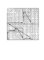
- FIG. 23 shows an example of intra prediction in conventional HEVC. Specifically, in FIG. 23, direction prediction is performed in the direction from the lower left to the upper right (the direction opposite to the direction indicated by the broken line arrow in FIG. 23), and the broken line arrow is used using the lower left reference pixel. Predict the top pixel.
- an arrow indicating the direction (prediction direction) of the prediction mode is assumed to be directed from the pixel subject to intra prediction to the reference pixel (same below), as described in the HEVC standard.
- CU Coding Unit
- TU Transform Unit
- a mode common to all TUs is used, but as a decoded reference pixel used in a TU that performs encoding processing next, a local part of a TU adjacent to the left side or the upper side of the TU.
- the decoded image can be reused.
- the decoded reference pixel (pixel after processing such as filtering) adjacent to the left side of CU # A is placed at the position indicated by the start point of the broken-line arrow in FIG. A prediction image is generated by extrapolation.
- FIG. 23 it is assumed that all reference pixels adjacent to the upper side and the left side of CU # A have been decoded.
- a specified value for example, “512” in the case of a 10-bit moving image
- a reference pixel to be used when generating a predicted image is created by the filling process.
- the encoding process is performed in the encoding order (Z scan order or raster scan order) of upper left CU ⁇ upper right CU ⁇ lower left CU ⁇ lower right CU. It may not be decrypted. In such a case, the predicted image is generated using a value obtained by extrapolating the nearest decoded reference pixel with zero order (see, for example, Non-Patent Document 1).
- FIG. 24 shows an example of intra prediction when TU partitioning is performed in conventional HEVC.
- FIG. 24B reference pixels located in TU # A1 (for example, white circles in FIG. 24B) have been decoded, but TU # A3 (in CU # A) Since the reference pixel (for example, the black circle in FIG. 24B) located in the lower left TU of FIG. 24B has not been decoded, a predicted image of TU # A2 (upper right TU in CU # A) is generated as it is. The reference pixel cannot be used.
- the value of the reference pixel (for example, “X” in FIG. 24B) located at the bottom of the decoded reference pixel located in TU # A1 is set to TU # A3 (CU It is specified to copy to an undecoded reference pixel (for example, a black circle in FIG. 24B) located in the same column in (lower left TU in #A).
- Non-Patent Document 2 A technique for improving the prediction accuracy by giving a degree of freedom is known (see Non-Patent Document 2).
- a CU is divided into a plurality of blocks (hereinafter referred to as “PU: Prediction Unit”) to which a prediction mode is assigned (hereinafter referred to as “N ⁇ ”). This is called “when N division is performed”).
- PU Prediction Unit
- N ⁇ a prediction mode assigned to a prediction mode assigned to a prediction mode assigned to a prediction mode assigned to a prediction mode.
- the PU encoding process is performed in the above-described Z-scan order, for example, when a prediction mode in a prediction direction other than the upper left is assigned to a certain PU, the reference pixel has not been decoded. Therefore, there is a problem that the prediction accuracy is lowered and the coding efficiency is reduced.
- the arrow indicating the prediction direction of the prediction mode is assumed to be directed from the pixel subject to intra prediction to the reference pixel as described in the H.265 / HEVC standard (the same applies hereinafter). ).
- FIG. 25 shows an example of intra prediction when CU # 1 is divided into PU # 0 to PU # 3 in the conventional H.265 / HEVC.
- the prediction mode in PU # 0 is “34”
- the prediction mode in PU # 1 is “2”
- the prediction mode in PU # 2 is “18”
- the prediction in PU # 3 It is assumed that the mode is “2”.
- Non-Patent Document 1 it is necessary to transmit a flag as to what encoding processing order is used for each CU, which increases the amount of information to be transmitted.
- An object is to provide an encoding device, a decoding device, and a program capable of improving accuracy and encoding efficiency.
- a first feature of the present invention is an encoding device configured to divide and encode a frame-unit original image constituting a moving image into encoding target blocks, and based on a prediction mode,
- a coding order control unit configured to determine a coding order of transform blocks in a coding target block, and decoding based on the coding order and a method of dividing the coding target block into the transform blocks
- the gist of the invention is to include a decoded image generation unit configured to generate an image.
- a second feature of the present invention is a decoding device configured to divide a frame-unit original image constituting a moving image into blocks to be encoded and decode the encoded image based on a prediction mode. Generating a decoded image based on a decoding order control unit configured to determine a decoding order of transform blocks in a target block, and a method of dividing the coding target block into the transform blocks;
- the gist of the present invention is to include a decoded image generation unit configured as described in (1).
- a third feature of the present invention is an encoding device configured to divide and encode an original image in frame units constituting a moving image into encoding target blocks, wherein the encoding target block is A coding order control unit configured to determine a coding order of the blocks based on a combination of the prediction modes in each of the blocks when divided into blocks each assigned a prediction mode; Further, the present invention includes a decoded image generation unit configured to generate a decoded image based on the encoding order and the method of dividing the encoding target block into the blocks.
- the fourth feature of the present invention is a decoding device configured to divide and decode a frame unit image constituting a moving image into encoding target blocks, and the encoding target blocks are respectively
- a decoding order controller configured to determine a decoding order of the block based on a combination of the prediction modes in each of the blocks, when the prediction mode is divided into blocks to be allocated;
- the gist of the present invention is to provide a decoded image generation unit configured to generate a decoded image based on a method of dividing the encoding target block into the blocks.
- the gist of the fifth feature of the present invention is that it is a program for causing a computer to function as the encoding device according to the first or third feature described above.
- the gist of a sixth feature of the present invention is that it is a program for causing a computer to function as the decoding device according to the second or fourth feature described above.
- an encoding apparatus that can improve prediction accuracy and encoding efficiency without increasing the amount of information transmitted by the encoding apparatus and without increasing the calculation time on the encoding apparatus side.
- a decoding device and a program can be provided.
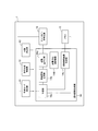
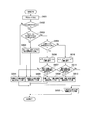
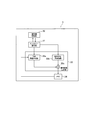
- FIG. 1 is a functional block diagram of an encoding apparatus 1 according to the first embodiment.
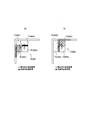
- FIG. 2 is a diagram illustrating an example of intra prediction when TU partitioning is performed in the first embodiment.
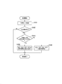
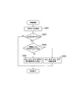
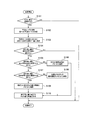
- FIG. 3 is a flowchart showing the operation of the encoding apparatus 1 according to the first embodiment.
- FIG. 4 is a functional block diagram of the decoding device 3 according to the first embodiment.
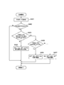
- FIG. 5 is a flowchart showing the operation of the decoding device 3 according to the first embodiment.
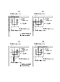
- FIG. 6 is a diagram illustrating an example of intra prediction when TU partitioning is performed in the second embodiment.
- FIG. 7 is a flowchart showing the operation of the encoding apparatus 1 according to the second embodiment.
- FIG. 1 is a functional block diagram of an encoding apparatus 1 according to the first embodiment.
- FIG. 2 is a diagram illustrating an example of intra prediction when TU partitioning is performed in the first embodiment.
- FIG. 3 is a flowchart showing the operation of the encoding apparatus 1
- FIG. 8 is a flowchart showing the operation of the decoding device 3 according to the second embodiment.
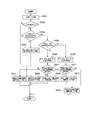
- FIG. 9 is a flowchart showing the operation of the encoding apparatus 1 according to the third embodiment.
- FIG. 10 is a flowchart showing the operation of the decoding device 3 according to the third embodiment.
- FIG. 11 is a diagram illustrating an example of a processing order index and a processing order corresponding to a divided shape when processing is performed sequentially from the left TU.
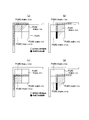
- FIG. 12 is a diagram illustrating an example of a method of dividing a CU into PUs according to the fourth embodiment.
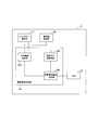
- FIG. 13 is a functional block diagram of the encoding device 1 according to the fourth embodiment.
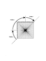
- FIG. 14 is a diagram illustrating an example of a prediction mode grouping method according to the fourth embodiment.
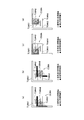
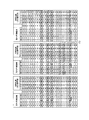
- FIG. 15 is a diagram illustrating an example of a table used for determining the encoding order and the decoding order in the fourth embodiment.
- FIG. 16 is a diagram illustrating an example of an encoding order and a decoding order in the fourth embodiment.
- FIG. 17 is a diagram illustrating an example of an encoding order and a decoding order in the fourth embodiment.
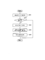
- FIG. 18 is a flowchart showing the operation of the encoding apparatus 1 according to the fourth embodiment.
- FIG. 19 is a functional block diagram of the decoding device 3 according to the fourth embodiment.
- FIG. 20 is a flowchart showing the operation of the decoding device 3 according to the fourth embodiment.
- FIG. 21 is a diagram illustrating an example of a table used for determining the encoding order and the decoding order in the fifth embodiment.
- FIG. 22 is a diagram illustrating an example of an encoding order and a decoding order in the fifth embodiment.
- FIG. 23 is a diagram illustrating an example of intra prediction in conventional HEVC.
- FIG. 24 is a diagram illustrating an example of intra prediction when TU partitioning is performed in conventional HEVC.
- FIG. 25 is a diagram for explaining the related art.
- the encoding device 1 and the decoding device 3 according to the first embodiment of the present invention will be described with reference to FIGS.
- the encoding device 1 and the decoding device 3 according to the present embodiment are configured to support intra prediction in a moving image encoding scheme such as HEVC.
- the encoding device 1 and the decoding device 3 according to the present embodiment are configured to be compatible with any video encoding scheme as long as the video encoding scheme performs intra prediction.
- the encoding apparatus 1 is configured to divide and encode a frame-unit original image constituting a moving image into CUs.
- the encoding device 1 according to the present embodiment is configured to be able to divide a CU into a plurality of TUs.
- a defined value for a CU to be encoded that does not have an adjacent decoded reference pixel, such as the CU positioned at the upper left in the frame, a defined value (for example, “512 for a 10-bit moving image”). ”Etc.) is created so as to create reference pixels to be used when generating a predicted image, so that all pixels adjacent to the left side of the encoding target CU can be used as reference pixels. To do.
- the encoding device 1 includes a prediction mode determination unit 11, a division determination unit 12, an encoding order control unit 13, a decoded image generation unit 14, a memory 15, And an entropy encoding unit 16.
- the prediction mode determination part 11 is comprised so that the optimal prediction mode applied to CU may be determined.
- the division determination unit 12 is configured to determine whether to divide a CU into a plurality of TUs.
- a method of dividing a CU into a plurality of TUs a case of four divisions is described as an example.
- the number of divisions and division shapes when a CU is divided into a plurality of TUs it is not limited to such a case.
- the encoding order control unit 13 is configured to determine the encoding order of the TUs in the CU based on the prediction mode (for example, the direction of the prediction mode).
- the encoding order control unit 13 When the direction of the prediction mode determined by the prediction mode determination unit 11 is the direction from the lower left to the upper right (that is, when direction prediction is performed from the lower left to the upper right), the encoding order of the TUs in the CU TU # A1 (upper left TU in CU # A) ⁇ TU # A3 (lower left TU in CU # A) instead of the conventional raster scan order (Z type as shown in FIG. 13) ⁇ The encoding order of TU # A2 (upper right TU in CU # A) ⁇ TU # A4 (lower right TU in CU # A) may be adopted.
- the encoding order control unit 13 determines that the division determination unit 12 determines to divide a CU into a plurality of TUs, and the prediction mode direction determined by the prediction mode determination unit 11 changes from the lower left to the upper right. (Ie, when direction prediction is performed from the upper right to the lower left, when Planar is performed, or when DC prediction is performed), the encoding order of TUs in the CU is the conventional encoding order.
- a raster scan order (Z-type as shown in FIG. 13) may be adopted.
- the encoding order determined by the encoding order control unit 13 can be uniquely determined by the direction of the prediction mode, there is no need to newly transmit a flag indicating the encoding order by the encoding device 1. .
- the decoded image generation unit 14 is configured to generate a local decoded image (decoded image for each TU) based on the encoding order determined by the encoding order control unit 13 and the method of dividing the CU into TUs. .
- the decoded image generation unit 14 sequentially, according to the encoding order determined by the encoding order control unit 13, It is configured to generate a locally decoded image.
- the decoded image generation unit 14 includes a prediction unit 14a, a residual signal generation unit 14b, a transform / quantization unit 14c, an inverse quantization / inverse transform unit 14d, and a local decoded image generation unit. 14e.
- the prediction unit 14a is configured to generate a prediction image using the prediction mode determined by the prediction mode determination unit 11.
- the prediction unit 14a determines that TU # A1 (upper left TU in CU # A) ⁇ TU # A3 (lower left TU in CU # A) ⁇ TU # A2 (upper right TU in CU # A) ⁇ TU Even if the encoding order of # A4 (lower right TU in CU # A) is employed, the prediction accuracy in TU # A3 does not decrease.
- the prediction unit 14a can use the reference pixel located within TU # A3 (lower left TU within CU # A) when generating a predicted image. The prediction accuracy in # A2 is improved.
- the prediction unit 14a uses a decoded reference pixel (for example, FIG. 2A) that is closest to an undecoded reference pixel (for example, a black circle in FIG. 2A).
- an undecoded reference pixel for example, a black circle in FIG. 2A.
- the TU # A2 (the upper right TU in the CU # A) is copied to an undecoded reference pixel located in the same column.
- the prediction unit 14a when the division determination unit 12 determines to divide a CU into a plurality of TUs, and when the prediction mode direction is from the lower left to the upper right, the prediction unit 14a As shown in FIG. 2 (b), when generating a prediction image of TU # A4 (lower right TU in CU # A), undecoded data embedded with a copy corresponding to the black circle in FIG. 2 (a) Since reference pixels are not used, it is possible to avoid a decrease in prediction accuracy and a decrease in coding efficiency.
- the prediction unit 14a when the division determination unit 12 determines to divide a CU into a plurality of TUs, and the prediction mode direction determined by the prediction mode determination unit 11 is a direction from upper right to lower left (that is, When the direction prediction is performed from the upper right to the lower left), the prediction unit 14a generates a predicted image in the conventional raster scan order (Z type as shown in FIG. 13).
- the residual signal generation unit 14b is configured to generate a residual signal based on the difference between the predicted image generated by the prediction unit 14a and the original image.
- the transform / quantization unit 14c is configured to perform orthogonal transform processing and quantization processing on the residual signal generated by the residual signal generation unit 14b to generate quantized transform coefficients.
- the inverse quantization / inverse transform unit 14d performs an inverse quantization process and an inverse orthogonal transform process again on the quantized transform coefficient generated by the transform / quantization unit 14c, thereby quantizing the residual signal. Is configured to generate
- the local decoded image generation unit 14e generates a local decoded image by adding the prediction image generated by the prediction unit 14a to the quantized residual signal generated by the inverse quantization / inverse conversion unit 14d. It is configured.
- the memory 15 is configured to hold the locally decoded image generated by the decoded image generation unit 14 so as to be usable as a reference image.
- the entropy encoding unit 16 is configured to perform entropy encoding processing on the flag information including the prediction mode determined by the prediction mode determination unit 11 and the quantized transform coefficient and output the stream.
- FIG. 3 shows a flowchart for explaining an example of the operation for determining the above-mentioned encoding order by the encoding apparatus 1 according to the present embodiment.
- step S101 the encoding device 1 determines an optimal prediction mode to be applied to the CU.
- step S102 the encoding apparatus 1 determines whether or not to divide a CU into a plurality of TUs. When it is determined in step S102 that the CU is divided into a plurality of TUs, the operation proceeds to step S103. On the other hand, when it is determined in step S102 that the CU is not divided into a plurality of TUs, this operation ends.
- step S103 When it is determined in step S103 that the direction of the prediction mode is from the lower left to the upper right (for example, in HEVC, when the prediction mode is determined to be “2” to “9”), The operation proceeds to step S105. On the other hand, when it is determined in step S103 that the direction of the prediction mode is not the direction from the lower left to the upper right, the operation proceeds to step S104.
- step S104 the encoding device 1 performs the encoding process in the raster scan order (Z type as shown in FIG. 13) used in the conventional HEVC.
- step S105 the encoding apparatus 1 determines TU # A1 (upper left TU in CU # A) ⁇ TU # A3 (lower left TU in CU # A) ⁇ TU # A2 (upper right TU in CU # A). ) ⁇ TU # A4 (lower right TU in CU # A) in the encoding order.
- the decoding device 3 according to the present embodiment is configured to divide and decode a frame-unit original image constituting a moving image into CUs. Also, the decoding device 3 according to the present embodiment is configured to be able to divide a CU into a plurality of TUs, similarly to the encoding device 1 according to the present embodiment.
- the decoding device 3 includes an entropy decoding unit 31, a decoding order control unit 32, a decoded image generation unit 33, and a memory 34.
- the entropy decoding unit 31 is configured to decode transform coefficients, flag information, and the like from the stream output from the encoding device 1.
- the transform coefficient is a quantized transform coefficient obtained by the encoding apparatus 1 as a signal encoded by dividing an original image in frame units into CUs.
- the flag information includes accompanying information such as a prediction mode.
- the decoding order control unit 32 is configured to determine the decoding order of the TUs in the CU based on the prediction mode.
- the decoding order control unit 32 indicates whether or not the TU division output by the entropy decoding unit 31 has been performed (whether or not the CU is divided into a plurality of TUs) and the direction of the prediction mode
- the decoding order of TUs in the CU is determined according to the above.
- the decoding order control unit 32 when the CU is divided into a plurality of TUs.
- the direction of the prediction mode output by the entropy decoding unit 31 is the direction from the lower left to the upper right (that is, when the direction prediction is performed from the lower left to the upper right)
- the decoding order of the TUs in the CU TU # A1 (upper left TU in CU # A) ⁇ TU # A3 (lower left TU in CU # A) instead of the conventional raster scan order (Z type as shown in FIG. 13) ⁇
- the encoding order of TU # A2 (upper right TU in CU # A) ⁇ TU # A4 (lower right TU in CU # A) may be adopted.
- the decoding order control unit 32 is a case where the CU is divided into a plurality of TUs and the direction of the prediction mode output by the entropy decoding unit 31 is not the direction from the lower left to the upper right (that is, from the upper right)
- the conventional raster scan order Z as shown in FIG. 13
- Type may be adopted.
- the decoding order determined by the decoding order control unit 32 can be uniquely determined by the direction of the prediction mode, it is not necessary for the decoding device 3 to newly receive a flag indicating the decoding order.
- the decoded image generation unit 33 is configured to generate a local decoded image (decoded image for each TU) based on the decoding order determined by the decoding order control unit 32 and the method of dividing the CU into TUs.
- the decoded image generation unit 33 performs the quantization output by the entropy decoding unit 31 according to the decoding order determined by the decoding order control unit 32 when the CU is divided into a plurality of TUs.
- a local decoded image is generated by sequentially performing intra prediction, inverse quantization processing, and inverse orthogonal transform processing on the transform coefficient.
- the decoded image generation unit 33 includes a predicted image generation unit 33a, an inverse quantization / inverse conversion unit 33b, and a local decoded image generation unit 33c.
- the predicted image generation unit 33a may be configured to generate a predicted image using the prediction mode output by the entropy decoding unit 31 in accordance with the decoding order determined by the decoding order control unit 32.
- the prediction image generation unit 33a when the CU is divided into a plurality of TUs, as illustrated in FIG. 2A and FIG. TU # A1 (upper left TU in CU # A) ⁇ TU # A3 (lower left TU in CU # A) ⁇ TU # A2 (CU) The decoding order of TU in the upper right in #A) ⁇ TU # A4 (lower right TU in CU #A) is adopted.
- the prediction image generation unit 33a is a case where the CU is divided into a plurality of TUs as in the prediction unit 14a, and the direction of the prediction mode determined by the prediction mode determination unit 11 is from the lower left to the upper right.
- the direction is not the direction (that is, when direction prediction is performed from upper right to lower left, when Planar is performed, or when DC prediction is performed)
- the conventional raster scan order Z-type as shown in FIG. 13) is used.
- the inverse quantization / inverse transform unit 33b performs an inverse quantization process and an inverse transform process (for example, an inverse orthogonal transform process) on the quantized transform coefficient output from the entropy decoding unit 31, thereby obtaining a residual. It is configured to generate a signal.
- an inverse transform process for example, an inverse orthogonal transform process
- the local decoded image generation unit 33c is configured to generate a local decoded image by adding the prediction image generated by the prediction image generation unit 33a and the residual signal generated by the inverse quantization / inverse conversion unit 33b. ing.
- the memory 34 is configured to hold the locally decoded image generated by the decoded image generation unit 33 so that it can be used as a reference image for intra prediction and inter prediction.
- FIG. 5 shows a flowchart for explaining an example of the operation for determining the decoding order described above by the decoding device 3 according to the present embodiment.
- step S ⁇ b> 201 the decoding device 3 acquires a prediction mode from the stream output from the encoding device 1.
- step S202 the decoding device 3 determines whether or not the CU is divided into a plurality of TUs based on the flag information included in the stream output from the encoding device 1. If it is determined in step S202 that the CU is divided into a plurality of TUs, the operation proceeds to step S203. On the other hand, when it is determined in step S202 that the CU is not divided into a plurality of TUs, this operation ends.
- step S203 the decoding device 3 determines whether or not the direction of the prediction mode is from the lower left to the upper right (for example, whether the prediction mode is “2” to “9” in HEVC). To do. If it is determined in step S203 that the direction of the prediction mode is not the direction from the lower left to the upper right, the operation proceeds to step S205. On the other hand, when it is determined in step S203 that the direction of the prediction mode is the direction from the lower left to the upper right, the operation proceeds to step S204.
- step S204 the decoding apparatus 3 determines TU # A1 (upper left TU in CU # A) ⁇ TU # A3 (lower left TU in CU # A) ⁇ TU # A2 (upper right TU in CU # A). ⁇ Decoding processing is performed in the decoding order of TU # A4 (lower right TU in CU # A).
- step S205 the decoding device 3 performs the decoding process in the conventional raster scan order used in HEVC (Z type as shown in FIG. 13).
- the encoding order and decoding order of TUs are uniquely determined according to the direction (prediction direction) of the prediction mode. Therefore, it is possible to reduce a decrease in prediction accuracy due to prediction based on undecoded reference pixels.
- the process procedure of the intra prediction is made common with the existing HEVC. be able to.
- the encoding apparatus 1 and the decoding apparatus 3 according to the second embodiment of the present invention are the same as the encoding apparatus 1 and the decoding apparatus 3 according to the first embodiment described above. The difference will be described below.
- the encoding order control unit 13 determines that the CU is divided into a plurality of TUs by the division determination unit 12 as shown in FIGS. 6 (a) to 6 (d). ), When the direction of the prediction mode determined by the prediction mode determination unit 11 is a direction from the lower left to the upper right (that is, when direction prediction is performed from the lower left to the upper right), TU # A3 (lower left TU in CU # A) ⁇ TU # A4 (lower right in CU # A) as the TU encoding order, not the conventional raster scan order (Z type as shown in FIG.
- TU) ⁇ TU # A1 (upper left TU in CU # A) ⁇ TU # A2 (upper right TU in CU # A) or TU # A3 (lower left TU in CU # A) ) ⁇ TU # A1 (upper left TU in CU # A) ⁇ TU # A4 CU lower right TU in # A) ⁇ TU # A2 (CU top right of TU in # A) of the coding order of, may be configured to employ a pre-defined coding order.
- the encoding order control unit 13 is a case where the division determination unit 12 determines to divide a CU into a plurality of TUs, and the prediction mode determination unit 11 When the determined prediction mode direction is from the upper right to the lower left (that is, when direction prediction is performed from the upper right to the lower left), the conventional raster scan order (Z type as shown in FIG. 13).
- TU # A2 (upper right TU in CU # A) ⁇ TU # A4 (lower right TU in CU # A) ⁇ TU # A1 (upper left TU in CU # A) ⁇ TU # A3 ( TU # A2 (upper right TU in CU # A) ⁇ TU # A1 (upper left TU in CU # A) ⁇ TU # A4 (CU #) Lower right TU in A) ⁇ TU # A3 (Left in CU # A Of TU) of coding order that may be configured to employ a pre-defined coding order.
- the prediction unit 14a is a case where the division determination unit 12 has determined to divide a CU into a plurality of TUs, and FIG. 6 (a) to FIG. 6 (d). As shown in FIG.
- TU # A3 lower left TU in CU # A
- TU # A4 lower right in CU # A
- TU ⁇ TU # A1 (upper left TU in CU # A) ⁇ TU # A2 (upper right TU in CU # A) or TU # A3 (lower left TU in CU # A) ⁇ TU # A1 (upper left TU in CU # A) ⁇ TU # A4 (lower right TU in CU # A) ⁇ TU # A2 (upper right TU in CU # A)
- You may be comprised so that a prediction image may be produced
- TU # A3 lower left TU in CU # A
- TU # A1 upper left in CU # A
- a decoded reference pixel at a closer position can be used as compared with a case where encoding processing in the conventional raster scan order is performed, and prediction accuracy is further improved.
- the prediction unit 14a includes TU # A1 (upper left TU in CU # A) in which the adjacent lower reference pixel is decoded, and
- TU # A2 upper right TU in CU # A
- the reference pixels used when generating the predicted image may be configured to be decoded reference pixels adjacent to the left side and the lower side.
- the prediction unit 14a is a case where the division determination unit 12 determines to divide a CU into a plurality of TUs, and the prediction mode direction (prediction direction) is.
- the direction is from the upper right to the lower left
- TU # A2 upper right TU in CU # A
- TU # A4 lower right TU in CU # A
- TU # A1 upper left in CU # A
- TU # A3 lower left TU in CU # A
- TU # A2 upper right TU in CU # A
- TU # A1 upper left TU in CU # A
- the prediction image is generated in a predetermined encoding order among the encoding orders of TU # A4 (lower right TU in CU # A) ⁇ TU # A3 (lower left TU in CU # A). It may be configured.
- the prediction unit 14a performs TU # A1 (upper left TU in CU # A) and TU # A3 (lower left TU in CU # A) in which adjacent right reference pixels are decoded.
- the reference pixels used when generating the predicted image may be configured to be decoded reference pixels adjacent to the upper side and the right side.
- FIG. 7 shows a flowchart for explaining an example of an operation for determining the above-mentioned encoding order by the encoding apparatus 1 according to the present embodiment.
- step S301 the encoding device 1 determines an optimal prediction mode to be applied to the CU.
- step S302 the encoding apparatus 1 determines whether or not to divide a CU into a plurality of TUs. If it is determined in step S102 that the CU is divided into a plurality of TUs, the operation proceeds to step S303. On the other hand, when it is determined in step S302 that the CU is not divided into a plurality of TUs, this operation ends.
- Step S303 when it is determined that the direction of the prediction mode is the direction from the lower left to the upper right or the direction from the upper right to the lower left, the operation proceeds to Step S305. On the other hand, if it is determined in step S303 that the direction of the prediction mode is other than the direction from the lower left to the upper right and the direction from the upper right to the lower left, the operation proceeds to step S304.
- step S304 the encoding apparatus 1 performs encoding processing in the raster scan order (Z type as shown in FIG. 13) used in the conventional HEVC.
- step S306 the encoding apparatus 1 determines TU # A3 (lower left TU in CU # A) ⁇ TU.
- # A4 lower right TU in CU # A) ⁇ TU # A1 (upper left TU in CU # A) ⁇ TU # A2 (upper right TU in CU # A) coding order or TU # A3 (lower left TU in CU # A) ⁇ TU # A1 (upper left TU in CU # A) ⁇ TU # A4 (lower right TU in CU # A) ⁇ TU # A2 (in CU # A)
- the encoding process is performed in a predetermined encoding order among the encoding orders of TU in the upper right.
- step S307 the encoding device 1 determines TU # A2 (upper right TU in CU # A) ⁇ TU # A4 (lower right TU in CU # A) ⁇ TU # A1 (upper left TU in CU # A) ⁇ TU # A3 (lower left TU in CU # A) or TU # A2 (upper right TU in CU # A) ⁇ TU # A1 (upper left TU in CU # A) ⁇ TU # A4 (lower right TU in CU # A) ⁇ TU # A3 (in CU # A)
- the encoding process is performed in a predetermined encoding order among the encoding orders of the lower left TU).
- the decoding order control unit 32 is a case where the CU is divided into a plurality of TUs and the direction of the prediction mode is lower left as in the encoding order control unit 13.
- TU # A3 lower left TU in CU # A) ⁇ TU # A4 (lower right TU in CU # A) ⁇ TU # A1 (upper left TU in CU # A) ) ⁇ TU # A2 (upper right TU in CU # A) or TU # A3 (lower left TU in CU # A) ⁇ TU # A1 (upper left TU in CU # A) ⁇ TU
- It is configured to perform decoding processing in a predetermined decoding order among decoding orders of # A4 (lower right TU in CU # A) ⁇ TU # A2 (upper right TU in CU # A). Also good.
- the decoding order control unit 32 is a case where the CU is divided into a plurality of TUs and the direction of the prediction mode is in the upper right as in the coding order control unit 13.
- TU # A2 (upper right TU in CU # A) ⁇ TU # A4 (lower right TU in CU # A) ⁇ TU # A1 (upper left TU in CU # A) ) ⁇ TU # A3 (lower left TU in CU # A) or TU # A2 (upper right TU in CU # A) ⁇ TU # A1 (upper left TU in CU # A) ⁇ TU
- the decoding process is performed in a predetermined decoding order. May be.
- the predicted image generation unit 33a is configured to generate a TU when the CU is divided into a plurality of TUs and the direction of the prediction mode is from the lower left to the upper right.
- the prediction image may be generated in a predetermined decoding order.
- the predicted image generation unit 33a performs TU # A1 (the upper left TU in CU # A) in which the adjacent lower reference pixel is decoded. ) And TU # A2 (upper right TU in CU # A), reference pixels used when generating a predicted image are configured to be decoded reference pixels adjacent to the left side and the lower side. Also good.
- the predicted image generation unit 33a is a case where the CU is divided into a plurality of TUs, and the direction of the prediction mode (prediction direction) is from the upper right to the lower left. If there is, TU # A2 (upper right TU in CU # A) ⁇ TU # A4 (lower right TU in CU # A) ⁇ TU # A1 (upper left TU in CU # A) ⁇ TU # A3 ( TU # A2 (upper right TU in CU # A) ⁇ TU # A1 (upper left TU in CU # A) ⁇ TU # A4 (CU # A) The prediction image may be generated in a predetermined decoding order in the decoding order of TU in the lower right) ⁇ TU # A3 (lower left TU in CU # A).
- the predicted image generation unit 33a applies to TU # A1 (upper left TU in CU # A) and TU # A3 (lower left TU in CU # A) in which adjacent right reference pixels are decoded.
- the reference pixels used when generating the predicted image may be configured to be decoded reference pixels adjacent to the upper side and the right side.
- FIG. 8 shows a flowchart for explaining an example of the operation of determining the decoding order described above by the decoding device 3 according to the present embodiment.
- step S401 the decoding device 3 acquires a prediction mode from the stream output from the encoding device 1.
- step S402 the decoding device 3 determines whether or not the CU is divided into a plurality of TUs based on the flag information included in the stream output from the encoding device 1. If it is determined in step S402 that the CU is divided into a plurality of TUs, the operation proceeds to step S403. On the other hand, when it is determined in step S402 that the CU is not divided into a plurality of TUs, this operation ends.
- step S403 the decoding apparatus 3 determines whether the direction of the prediction mode is a direction from the lower left to the upper right or a direction from the upper right to the lower left. If it is determined in step S403 that the direction of the prediction mode is the direction from the lower left to the upper right or the direction from the upper right to the lower left, the operation proceeds to step S405. On the other hand, if it is determined in step S403 that the direction of the prediction mode is other than the direction from the lower left to the upper right and the direction from the upper right to the lower left, the operation proceeds to step S404.
- step S404 the decoding device 3 performs the decoding process in the conventional raster scan order used in HEVC (Z type as shown in FIG. 13).
- step S406 the decoding device 3 determines that TU # A3 (lower left TU in CU # A) ⁇ TU #.
- step S407 the decoding device 3 determines that TU # A2 (upper right TU in CU # A) ⁇ TU.
- Decoding order of # A4 (lower right TU in CU # A) ⁇ TU # A1 (upper left TU in CU # A) ⁇ TU # A3 (lower left TU in CU # A) or TU # A2 (Upper right TU in CU # A) ⁇ TU # A1 (upper left TU in CU # A) ⁇ TU # A4 (lower right TU in CU # A) ⁇ TU # A3 (lower left in CU # A)
- the decoding process is performed in a predetermined decoding order among the decoding orders of (TU).
- the encoding device 1 and the decoding device 3 when a CU is divided into a plurality of TUs, more accurate intra prediction is performed according to the direction (prediction direction) of the prediction mode. Can do.
- a predetermined encoding order different from the conventional raster scan order is used according to the direction of the prediction mode, and the left side or the upper side of the TU to be encoded.
- the prediction unit 14a uses all available reference pixels. It may be configured to perform intra prediction by changing to another predetermined prediction such as linear interpolation.
- the prediction unit 14a determines TU # A3 (lower left TU in CU # A) ⁇ TU # A4 (in CU # A).
- TU # A1 upper left TU in CU # A
- TU # A2 upper right TU in CU # A
- the common prediction direction is used regardless of the position of the divided TU.
- reference pixels adjacent to TU # A1 (upper left TU in CU # A) and TU # A2 (upper right TU in CU # A) are already decoded except for reference pixels adjacent to the right side of TU # A1 (upper left TU in CU # A) and TU # A2 (upper right TU in CU # A).
- TU # A3 lower left TU in CU # A
- TU # A4 lower right TU in CU # A
- TU # A1 in CU # A
- TU # A2 upper left TU in CU # A
- TU # A3 lower left TU in CU # A
- TU # A1 upper left in CU # A
- TU # A4 lower right TU in CU # A
- TU # A2 upper right TU in CU # A
- the prediction unit 14a For TUs in which adjacent reference pixels have been decoded (TUs located at the uppermost stage among the divided TU groups, TU # A1 and TU # A2 in the example of FIG. 6), a common intra in CU # A.
- a common intra in CU # A Use decoded reference pixels adjacent to the left side, upper side, or lower side of the TU, not the prediction direction It may be configured to perform
- FIG. 9 shows a flowchart for explaining an example of an operation for determining the above-mentioned encoding order by the encoding apparatus 1 according to the present embodiment.
- step S501 the encoding device 1 determines an optimal prediction mode to be applied to the CU.
- step S502 the encoding apparatus 1 determines whether or not to divide a CU into a plurality of TUs. When it is determined in step S502 that the CU is divided into a plurality of TUs, the operation proceeds to step S503. On the other hand, if it is determined in step S502 that the CU is not divided into a plurality of TUs, the operation proceeds to step S508.
- step S503 when it is determined that the direction of the prediction mode is the direction from the lower left to the upper right or the direction from the upper right to the lower left, the operation proceeds to step S505.
- step S503 when it is determined in step S503 that the direction of the prediction mode is other than the direction from the lower left to the upper right and the direction from the upper right to the lower left, the operation proceeds to step S504.
- step S504 the encoding apparatus 1 employs the raster scan order (Z type as shown in FIG. 13) used in the conventional HEVC as the above-described encoding order.
- step S508 the encoding apparatus 1 performs a predetermined prediction on the TU to be encoded using the decoded reference pixels adjacent to the left side and the upper side of the TU.
- step S506 the encoding device 1 uses TU # A3 (in CU # A) as the encoding order described above.
- TU # A4 lower right TU in CU # A
- TU # A1 upper left TU in CU # A
- TU # A2 upper right TU in CU # A
- TU # A3 lower left TU in CU # A
- TU # A1 upper left TU in CU # A
- TU # A4 lower right TU in CU # A
- TU # A4 lower right TU in CU # A
- step S510 the encoding device 1 sets TU # A2 (CU # A) as the above-described encoding order.
- TU # A4 (lower right TU in CU # A) ⁇ TU # A1 (upper left TU in CU # A) ⁇ TU # A3 (lower left TU in CU # A) TU # A2 (upper right TU in CU # A) ⁇ TU # A1 (upper left TU in CU # A) ⁇ TU # A4 (lower right TU in CU # A) ⁇ TU Among the encoding orders of # A3 (lower left TU in CU # A), a predetermined encoding order is adopted.
- step S507 the encoding apparatus 1 determines whether or not the reference pixel adjacent to the upper side of the TU to be encoded has been decoded. In step S507, if the decoding has been completed, the operation proceeds to step S509. If the decoding has not been completed, the operation proceeds to step S514.
- step S509 the encoding apparatus 1 performs a predetermined prediction on the TU to be encoded using the decoded reference pixels adjacent to the left side, the upper side, and the lower side of the TU.
- step S514 the encoding apparatus 1 performs a predetermined prediction on the TU to be encoded using the decoded reference pixels adjacent to the left side and the lower side of the TU.
- step S511 the encoding apparatus 1 determines whether or not the reference pixel adjacent to the left side of the TU to be encoded has been decoded. In step S511, if the decoding has been completed, the operation proceeds to step S512. If the decoding has not been completed, the operation proceeds to step S513.
- step S512 the encoding apparatus 1 performs a predetermined prediction on the TU to be encoded using decoded reference pixels adjacent to the left side, the upper side, and the right side of the TU.
- step S513 the encoding apparatus 1 performs a predetermined prediction on the TU to be encoded using the decoded reference pixels adjacent to the right side and the upper side of the TU.
- a predetermined decoding order different from the conventional raster scan order is used according to the direction of the prediction mode, and adjacent to the left side, the upper side, or the right side of the decoding target TU.
- the predicted image generation unit 33a performs linear operation using all available reference pixels. It may be configured to perform intra prediction by changing to another predetermined prediction such as interpolation.
- FIG. 10 shows a flowchart for explaining an example of the operation of determining the above decoding order by the decoding device 3 according to the present embodiment.
- step S ⁇ b> 601 the decoding device 3 acquires a prediction mode from the stream output from the encoding device 1.
- step S602 the decoding device 3 determines whether the CU is divided into a plurality of TUs based on the flag information included in the stream output from the encoding device 1. When it is determined in step S602 that the CU is divided into a plurality of TUs, the operation proceeds to step S603. On the other hand, if it is determined in step S602 that the CU is not divided into a plurality of TUs, the operation proceeds to step S608.
- step S608 the decoding device 3 performs a predetermined prediction on the decoding target TU using the decoded reference pixels adjacent to the left side and the upper side of the TU.
- step S603 the decoding device 3 determines whether the direction of the prediction mode is the direction from the lower left to the upper right or the direction from the upper right to the lower left. If it is determined in step S603 that the direction of the prediction mode is the direction from the lower left to the upper right or the direction from the upper right to the lower left, the operation proceeds to step S605. On the other hand, if it is determined in step S603 that the direction of the prediction mode is other than the direction from the lower left to the upper right and the direction from the upper right to the lower left, the operation proceeds to step S604.
- step S604 the decoding device 3 employs the conventional raster scan order (Z type as shown in FIG. 13) used in HEVC as the above-described decoding order.
- step S606 the decoding device 3 determines TU # A3 (lower left in CU # A as the decoding order).
- TU ⁇ TU # A4 (lower right TU in CU # A) ⁇ TU # A1 (upper left TU in CU # A) ⁇ TU # A2 (upper right TU in CU # A)
- TU # A3 lower left TU in CU # A) ⁇ TU # A1 (upper left TU in CU # A)
- TU # A4 lower right TU in CU # A) ⁇ TU # A2 (CU Among the decoding orders of TU in the upper right in #A)
- a predetermined decoding order is adopted.
- step S610 the decoding device 3 uses TU # A2 (in CU # A as the decoding order).
- Upper right TU) ⁇ TU # A4 lower right TU in CU # A) ⁇ TU # A1 (upper left TU in CU # A) ⁇ TU # A3 (lower left TU in CU # A)
- TU # A2 upper right TU in CU # A
- TU # A1 upper left TU in CU # A
- TU # A4 lower right TU in CU # A
- TU # A3 Among the decoding orders of TU # A (lower left TU), a predetermined decoding order is adopted.
- step S607 the decoding device 3 determines whether the reference pixel adjacent to the upper side of the decoding target TU has been decoded. In step S607, when the decoding has been completed, the operation proceeds to step S609. When the decoding has not been completed, the operation proceeds to step S614.
- step S609 the decoding device 3 performs a predetermined prediction on the decoding target TU using the decoded reference pixels adjacent to the left side, the upper side, and the lower side of the TU.
- step S614 the decoding device 3 performs a predetermined prediction on the decoding target TU using the decoded reference pixels adjacent to the left side and the lower side of the TU.
- step S611 the decoding device 3 determines whether the reference pixel adjacent to the left side of the decoding target TU has been decoded. In step S611, if the decoding has been completed, the operation proceeds to step S612. If the decoding has not been completed, the operation proceeds to step S613.
- step S612 the decoding device 3 performs a predetermined prediction on the decoding target TU using the decoded reference pixels adjacent to the left side, the upper side, and the right side of the TU.
- step S613 the decoding device 3 performs a predetermined prediction on the decoding target TU using the decoded reference pixels adjacent to the right side and the upper side of the TU.
- the encoding device 1 and the decoding device 3 according to the direction of the prediction mode and the position of the encoding target (or decoding target) TU, that is, in the position and direction of the reference pixels that can be used. Accordingly, since the prediction mode itself applied to the encoding target (or decoding target) TU can be switched, the prediction accuracy can be further improved.
- the encoding device 1 and the decoding device 3 according to the present embodiment are configured to support intra prediction in a moving image encoding scheme such as H.265 / HEVC.
- the encoding device 1 and the decoding device 3 according to the present embodiment are configured to be compatible with any video encoding scheme as long as the video encoding scheme performs intra prediction.
- the encoding apparatus 1 is configured to divide and encode a frame-unit original image constituting a moving image into encoding target blocks.
- a case in which “CU” used in the current H.265 / HEVC is used as an example of the encoding target block will be described as an example.
- the present invention is limited to such a case.
- the present invention can be applied to a case where an encoding target block with another name is used.
- the encoding device 1 is configured to be able to divide the encoding target block into a plurality of blocks.
- a prediction mode is assigned to each of such blocks.
- PU used in the current H.265 / HEVC
- the present invention is not limited to such a case. It is also applicable to cases where other named blocks are used.
- a defined value for a CU to be encoded that does not have an adjacent decoded reference pixel, such as the CU located at the upper left in the frame, a defined value (for example, “512 for a 10-bit moving image”). ”Etc.) is created so as to create reference pixels to be used when generating a predicted image, so that all pixels adjacent to the left side of the encoding target CU can be used as reference pixels. To do.
- the encoding device 1 includes a prediction mode determination unit 11, a division determination unit 12, a coding order control unit 13, a decoded image generation unit 14, a memory 15, An entropy encoding unit 16 and a recalculation control unit 17 are provided.
- the prediction mode determination part 11 is comprised so that the suitable prediction mode applied to CU and PU may be determined.
- the prediction mode takes any value from “0” to “34”, and the prediction mode 0 corresponds to the Planar prediction, and the prediction mode 1 corresponds to DC prediction.
- the prediction mode is divided into three regions, the prediction modes 2 to 9 belong to the prediction region A, the prediction modes 0, 1, 10 to 26 belong to the prediction region B, and the prediction modes 27 to 34 are Suppose that it belongs to the prediction region C.
- the prediction mode belongs to the prediction area A, and the reference pixel is on the upper right side from the center of CU and PU. In some cases (when the prediction direction is upper right), the prediction mode belongs to the prediction region C, and in other cases, the prediction mode belongs to the prediction region B.
- the present invention can also be applied to a case where the number of prediction modes is larger than “35” in the current H.265 / HEVC.
- the division determination unit 12 is configured to determine whether to divide a CU (CU # 1 in this embodiment) into a plurality of PUs (PU # 0 to PU # 3 in this embodiment). .
- a case of four divisions is described as an example.
- the number of divisions and division shapes when a CU is divided into a plurality of PUs is not limited to such a case.
- the encoding order control unit 13 is determined by the division determination unit 12 to divide the CU (CU # 1 in this embodiment) into a plurality of PUs (PU # 0 to PU # 3 in this embodiment). In this case, the PU coding order is determined based on the combination of prediction modes in each PU determined by the prediction mode determination unit 11.
- the encoding order control unit 13 may be configured to determine the encoding order of PUs so that the most decoded reference pixels are used when generating a predicted image.
- the encoding order control unit 13 determines the PU encoding order based on the table shown in FIG. May be configured to determine.
- the encoding order control unit 13 is a case where the division determination unit 12 determines to divide CU # 1 into PU # 0 to PU # 3, and the case of (1) in FIG.
- the prediction mode in PU # 0 belongs to prediction region A
- the prediction mode in PU # 1 belongs to prediction region A
- the prediction mode in PU # 2 belongs to prediction region B
- the prediction mode in PU # 3 is When belonging to the prediction region B (for example, as shown in FIG. 16, the prediction mode in PU # 0 is “2”, the prediction mode in PU # 1 is “2”, and the prediction mode in PU # 2 is “2”).
- 18 and the prediction mode in PU # 3 is“ 18 ”), not the conventional Z scan order as shown in FIGS.
- PU # 0 PU # 2 (upper left PU in CU # 1)
- PU # 2 (lower left PU in CU # 1)
- PU # 1 (upper right PU in CU # 1)
- PU # 3 (lower right PU in CU # 1)
- the encoding order of (PU) may be adopted.
- the encoding order control unit 13 is a case where the division determination unit 12 determines to divide CU # 1 into PU # 0 to PU # 3, and as in the case of (2) in FIG. , The prediction mode in PU # 0 belongs to prediction region C, the prediction mode in PU # 1 belongs to prediction region A, the prediction mode in PU # 2 belongs to prediction region B, and the prediction mode in PU # 3 is prediction region A. (For example, as shown in FIG. 17, the prediction mode for PU # 0 is “34”, the prediction mode for PU # 1 is “2”, and the prediction mode for PU # 2 is “18”. Yes, when the prediction mode in PU # 3 is “2”), the conventional Z-scan order as shown in FIGS.
- the combination of the prediction region and the encoding order (or decoding order) of each PU is not limited to the combination shown in FIG. 15, and other effects (for example, improvement in encoding speed or encoding processing) Other combinations may be used.
- the recalculation control unit 17 is configured to selectively erase and recalculate a part of block data in the memory 15 held so as to be used as a reference image.
- the recalculation control unit 17 uses the division determination unit 12 to divide the CU (CU # 1 in this embodiment) into a plurality of PUs (PU # 0 to PU # 3 in this embodiment). Is determined, and the encoding order of the PU determined by the encoding order control unit 13 is not the conventional Z scan order as shown in FIGS. 25 (a) to 25 (d).
- the PU encoding order determined by the encoding order control unit 13 is compared with the conventional Z scan order from the beginning, and already generated for all PUs after the PU having a different encoding order.
- the decoded image is erased, and thereafter, encoding processing is performed in a new encoding order using a new reference pixel, and a decoded image is generated and stored in the memory 15.
- the recalculation control unit 17 causes the encoding order control unit 13 to execute PU # 0 (upper left PU in CU # 1) ⁇ PU # 2 (lower left PU in CU # 1) ⁇ PU # 1 (CU When it is decided to adopt an encoding order (see FIG. 16A to FIG.
- the recalculation control unit 17 causes the encoding order control unit 13 to execute PU # 0 (upper left PU in CU # 1) ⁇ PU # 2 (lower left PU in CU # 1) ⁇ PU # 3 ( It was decided to adopt the encoding order (see FIG. 17 (a) to FIG. 17 (d)) of PU # 1 (lower right PU in CU # 1) ⁇ PU # 1 (upper right PU in CU # 1).
- the decoded image generation unit 14 determines the PU coding order determined by the coding order control unit 13 and the PU of the CU (CU # 1 in this embodiment) (PU # 0 to PU # 3 in this embodiment). The decoded image for each PU is generated based on the division method.
- the decoded image generation unit 14 is determined by the encoding order control unit 13 when the division determination unit 12 determines to divide CU # 1 into a plurality of PU # 0 to PU # 3.
- a decoded image for each PU is sequentially generated according to the encoding order of the PUs.
- the decoded image generation unit 14 includes a prediction unit 14a, a residual signal generation unit 14b, a transform / quantization unit 14c, an inverse quantization / inverse transform unit 14d, and a local decoded image generation unit. 14e.
- the prediction unit 14a is configured to generate a prediction image using the prediction mode determined by the prediction mode determination unit 11. That is, the prediction unit 14a is configured to determine the position of the reference pixel used when generating the predicted image.
- the prediction unit 14a is a case where the division determination unit 12 determines to divide CU # 1 into a plurality of PU # 0 to PU # 3, and in the case of (1) in FIG.
- the prediction mode in PU # 0 belongs to prediction region A
- the prediction mode in PU # 1 belongs to prediction region A
- the prediction mode in PU # 2 belongs to prediction region B
- the prediction mode in PU # 3 is predicted.
- the region B for example, the case of FIG. 16
- PU # 0 upper left PU in CU # 1)
- PU # 2 (CU #) 1 is configured to generate a prediction image in the encoding order of PU # 1 (lower left PU in CU # 1) ⁇ PU # 1 (upper right PU in CU # 1) ⁇ PU # 3 (lower right PU in CU # 1). May be.
- the prediction unit 14a when the division determination unit 12 determines to divide CU # 1 into a plurality of PU # 0 to PU # 3, and as in the case of (2) in FIG.
- the prediction mode in PU # 0 belongs to prediction region C
- the prediction mode in PU # 1 belongs to prediction region A
- the prediction mode in PU # 2 belongs to prediction region B
- the prediction mode in PU # 3 belongs to prediction region A.
- PU # 0 upper left PU in CU # 1) ⁇ PU # 2 (in CU # 1) It is configured to generate a prediction image in the encoding order of PU (lower left PU) ⁇ PU # 3 (lower right PU in CU # 1) ⁇ PU # 1 (upper right PU in CU # 1). Also good.
- the prediction unit 14a of the decoded image generation unit 14 may be configured to generate a prediction image in consideration of the distance between the pixels of PU # 0 to PU # 3 and the decoded reference pixels.
- the prediction unit 14a is configured to generate a prediction image of PU # 1 using decoded reference pixels in the PU adjacent to the lower side of PU # 1. It may be.
- the residual signal generation unit 14b is configured to generate a residual signal based on the difference between the predicted image generated by the prediction unit 14a and the original image.
- the transform / quantization unit 14c performs transform processing (for example, orthogonal transform processing) and quantization processing on the residual signal generated by the residual signal generation unit 14b, and generates a quantized transform coefficient. It is configured.
- the inverse quantization / inverse transform unit 14d performs the inverse quantization process and the inverse orthogonal transform process again on the quantized transform coefficient generated by the transform / quantization unit 14c to generate a residual signal. It is configured.
- the local decoded image generation unit 14e generates a local decoded image for each PU by adding the prediction image generated by the prediction unit 14a to the residual signal generated by the inverse quantization / inverse conversion unit 14d. It is configured.
- the entropy encoding unit 16 is configured to perform entropy encoding processing on the flag information including the prediction mode determined by the prediction mode determination unit 11 and the quantized transform coefficient and output the stream.
- the memory 15 is configured to hold the decoded image for each PU generated by the decoded image generation unit 14 so that it can be used as a reference image.
- step S101 the encoding apparatus 1 divides a CU (CU # 1 in this embodiment) into a plurality of PUs (PU # 0 to PU # 3 in this embodiment). Whether or not (N ⁇ N division is applied) is determined.
- step S102 If “Yes”, the operation proceeds to step S102, and if “No”, the operation ends.
- step S102 the encoding apparatus 1 determines a prediction mode to be applied to each of PU # 0 to PU # 3.
- step S103 the encoding device 1 uniquely determines the encoding order of PUs based on the combination of prediction modes in each PU.
- step S104 the encoding apparatus 1 determines whether or not the PU encoding order determined in step S103 is different from the conventional Z scan order.
- step S105 If “Yes”, the operation proceeds to step S105, and if “No”, the operation ends.
- step S105 the encoding apparatus 1 determines whether or not the leading PU in the PU coding order determined in step S103 is the same as the leading PU in the conventional Z scan order.
- step S107 If “Yes”, the operation proceeds to step S107, and if “No”, the operation proceeds to step S106.
- step S106 the encoding apparatus 1 deletes all the decoded images of PU # 0 to PU # 3 from the memory. Thereafter, the operation proceeds to step S110, and the encoding apparatus 1 performs recalculation using the PU encoding order determined in step S103, and generates decoded images of all PUs # 0 to PU # 3.
- step S107 the encoding apparatus 1 determines whether or not the second PU in the encoding order of the PU determined in step S103 is the same as the second PU in the conventional Z scan order.
- step S109 If “Yes”, the operation proceeds to step S109, and if “No”, the operation proceeds to step S108.
- step S108 the encoding device 1 deletes the decoded image of the PU other than the head from the memory. Thereafter, the operation proceeds to step S110, and the encoding apparatus 1 performs recalculation using the PU encoding order determined in step S103, and generates decoded images of the second and subsequent PUs.
- step S109 the encoding apparatus 1 deletes the decoded images of the third and subsequent PUs from the memory, and in step S110, performs recalculation using the PU encoding order determined in step S103, and performs the third and subsequent PUs.
- the decoded image is generated.
- the encoding device 1 According to the encoding device 1 according to the present embodiment, it is possible to prevent a reduction in encoding efficiency without increasing the amount of data to be transmitted.
- the decoding device 3 according to the present embodiment is configured to divide and decode a frame unit image constituting a moving image into CUs. Also, the decoding device 3 according to the present embodiment is configured to be able to divide a CU into a plurality of PUs, similarly to the encoding device 1 according to the present embodiment.
- the decoding device 3 includes an entropy decoding unit 21, a decoding order control unit 22, a decoded image generation unit 23, and a memory 24.
- the entropy decoding unit 21 is configured to decode transform coefficients, flag information, and the like from the stream output from the encoding device 1 by performing entropy decoding processing on the stream output from the encoding device 1. ing.
- the transform coefficient is the above-described quantized transform coefficient obtained by the encoding apparatus 1 as a signal encoded by dividing an original image in frame units into CUs.
- the flag information includes accompanying information such as a prediction mode.
- the decoding order control unit 22 is configured to determine the decoding order of PUs based on the prediction mode of each PU.
- the decoding order control unit 22 indicates whether or not the N ⁇ N division output by the entropy decoding unit 21 has been performed (whether or not the CU is divided into a plurality of PUs) and a prediction mode.
- the decoding order of PUs in a CU is determined according to the direction of the CU.
- the decoding order control unit 22 may be configured to determine the decoding order of PUs so as to use the most decoded reference pixels when generating a predicted image.
- the decoding order of PUs may be determined based on the same table as the table.
- the decoding order control unit 22 performs prediction in PU # 0 when CU # 1 is divided into PU # 0 to PU # 3 and as in the case of (1) in FIG.
- the prediction mode in PU # 1 belongs to the prediction area A
- the prediction mode in PU # 2 belongs to the prediction area B
- the prediction mode in PU # 3 belongs to the prediction area B (for example, As shown in FIG. 16, the prediction mode in PU # 0 is “2”, the prediction mode in PU # 1 is “2”, the prediction mode in PU # 2 is “18”, and in PU # 3
- the prediction mode is “18”
- FIGS. 16 (a) to 16 (d) instead of the conventional Z scan order as shown in FIGS.
- PU # 0 upper left PU in CU # 1) ⁇ PU # It is configured to adopt a decoding order of (lower left PU in CU # 1) ⁇ PU # 1 (upper right PU in CU # 1) ⁇ PU # 3 (lower right PU in CU # 1). May be.
- the decoding order control unit 22 predicts the prediction mode in PU # 0 when CU # 1 is divided into PU # 0 to PU # 3 and as in the case of (2) in FIG.
- the prediction mode in PU # 1 belongs to region C
- the prediction mode in PU # 1 belongs to prediction region A
- the prediction mode in PU # 2 belongs to prediction region B
- the prediction mode in PU # 3 belongs to prediction region A (for example, in FIG.
- the prediction mode in PU # 0 is “34”
- the prediction mode in PU # 1 is “2”
- the prediction mode in PU # 2 is “18”
- the prediction mode in PU # 3 is In the case of “2”), as shown in FIGS.
- the PU # 0 is not in the conventional Z-scan order as shown in FIGS. 25 (a) to 25 (d).
- (PU at the upper left in CU # 1) ⁇ PU # 2 It is configured to adopt a decoding order of PU # 3 (lower left PU in U # 1) ⁇ PU # 3 (lower right PU in CU # 1) ⁇ PU # 1 (upper right PU in CU # 1). Also good.
- the decoded image generation unit 23 determines the decoding order of the PU determined by the decoding order control unit 22 and the PU (PU # 0 to PU # 3 in this embodiment) of the CU (CU # 1 in this embodiment). Based on the division method, a decoded image is generated for each PU.
- the decoded image generation unit 23 sequentially performs according to the PU coding order determined by the decoding order control unit 22.
- the decoded image is generated for each PU.
- the decoded image generation unit 23 performs the entropy decoding unit according to the decoding order determined by the decoding order control unit 22. 21. It is configured to generate a decoded image for each PU by sequentially performing a predicted image generation process, an inverse quantization process, and an inverse orthogonal transform process on the quantized transform coefficient output by 21. .
- the decoded image generation unit 23 includes a predicted image generation unit 23a, an inverse quantization / inverse conversion unit 23b, and a local decoded image generation unit 23c.
- the predicted image generation unit 23 a may be configured to generate a predicted image using the prediction mode output by the entropy decoding unit 21 according to the decoding order determined by the decoding order control unit 22.
- the predicted image generation unit 23a uses the PU # 0 when the CU # 1 is divided into a plurality of PUs # 0 to PU # 3 and as in the case of (1) in FIG.
- the prediction mode in PU # 1 belongs to the prediction region A
- the prediction mode in PU # 1 belongs to the prediction region A
- the prediction mode in PU # 2 belongs to the prediction region B
- the prediction mode in PU # 3 belongs to the prediction region B ( For example, as shown in FIGS. 16A to 16D) and FIGS.
- PU # 0 (upper left PU in CU # 1) ⁇ PU # 2
- the prediction image is generated in the decoding order of (lower left PU in CU # 1) ⁇ PU # 1 (upper right PU in CU # 1) ⁇ PU # 3 (lower right PU in CU # 1). It may be configured.
- the prediction unit 23a predicts the prediction mode in PU # 0 when CU # 1 is divided into a plurality of PU # 0 to PU # 3 and as in the case of (2) in FIG.
- the prediction mode in PU # 1 belongs to region C
- the prediction mode in PU # 1 belongs to prediction region A
- the prediction mode in PU # 2 belongs to prediction region B
- the prediction mode in PU # 3 belongs to prediction region A (for example, FIG. Case), as shown in FIGS.
- the prediction image may be generated in the decoding order of (lower right PU in CU # 1) ⁇ PU # 1 (upper right PU in CU # 1).
- the predicted image generation unit 23a of the decoded image generation unit 23 may be configured to generate a predicted image in consideration of the distance between the pixels of PU # 0 to PU # 3 and the decoded reference pixels. .
- the predicted image generation unit 23a generates a predicted image of PU # 1 using the decoded reference pixels in the PU adjacent to the lower side of PU # 1. It may be configured.
- the inverse quantization / inverse transform unit 23b performs an inverse quantization process and an inverse transform process (for example, an inverse orthogonal transform process) on the quantized transform coefficient output from the entropy decoding unit 21, thereby obtaining a residual. It is configured to generate a signal.
- an inverse transform process for example, an inverse orthogonal transform process
- the local decoded image generation unit 23c is configured to generate a decoded image for each PU by adding the prediction image generated by the prediction unit 23a and the residual signal generated by the inverse quantization / inverse conversion unit 23b. ing.
- the memory 24 is configured to hold the decoded image for each PU generated by the decoded image generation unit 23 so that it can be used as a reference image for intra prediction and inter prediction.
- step S201 the decoding device 3 acquires transform coefficients and flag information from the stream output from the encoding device 1.
- step S202 the decoding device 3 determines that a CU (CU # 1 in the present embodiment) includes a plurality of PUs (in the present embodiment, CU # 1) based on the flag information included in the stream output from the encoding device 1. It is determined whether or not it is divided into (PU # 0 to PU # 3) (whether or not N ⁇ N division is applied).
- step S203 If “Yes”, the operation proceeds to step S203, and if “No”, the operation ends.
- step S203 the decoding apparatus 3 acquires each prediction mode of PU # 0 to PU # 3 based on the flag information included in the stream output from the encoding apparatus 1.
- step S204 the decoding device 3 uniquely determines the decoding order of PUs based on the combination of prediction modes in each of PU # 0 to PU # 3.
- step S205 the decoding device 3 generates decoded images of PU # 0 to PU # 3 according to the decoding order of PUs determined in step S204.
- the decoding device 3 can prevent a reduction in encoding efficiency without increasing the amount of data to be transmitted.
- whether or not the prediction unit 14a of the decoded image generation unit 14 uses a prediction mode that uses decoded reference pixels in a plurality of PUs adjacent to the PU as a prediction mode. Is configured to generate a predicted image.
- prediction modes using decoded reference pixels in a plurality of PUs adjacent to the PU include Planar prediction and DC prediction, but the prediction mode is not limited to these and is adjacent to the PU.
- An arbitrary prediction mode using decoded reference pixels in a plurality of PUs may be used.
- the prediction unit 14a of the decoded image generation unit 14 when pixels in a three-directional or omnidirectional PU adjacent to the encoding target PU have been decoded in the encoding order determined by the prediction mode determination unit 11 When Planar prediction or DC prediction is assigned to such a PU, the prediction unit 14a of the decoded image generation unit 14 generates a prediction image using all available reference pixels.
- the coding order control unit 13 may be configured to determine the coding order of PUs based on the table shown in FIG.
- the table shown in FIG. 21 is different from the table shown in FIG. 15 in the hatched portion.
- the table shown in FIG. 15 is created with priority given to shortening the time required for the encoding process (or decoding process), that is, as shown in FIGS. 25A to 25D as much as possible.
- the table shown in FIG. 21 considers the use of reference pixels in PUs that are adjacent to the encoding target (decoding target) PU in three or all directions when using Planar prediction or DC prediction. Created with priority given to improving prediction accuracy.
- the encoding order control unit 13 only shows the prediction mode B in the portion of the prediction region B in the hatched portion in the table shown in FIG. 21 when the prediction mode is Planar prediction or DC prediction.
- the encoding order of PUs may be determined based on the table, and otherwise, the encoding order of PUs may be determined based on the table shown in FIG.
- the prediction system can be improved without increasing the time required for the encoding process (or decoding process). .
- the combination of the prediction region and the encoding order (or decoding order) of each PU is not limited to the combination shown in FIG. 21, and other effects (for example, improvement in encoding speed and encoding processing) Other combinations may be used.
- the encoding order control unit 13 is a case where the division determination unit 12 determines to divide CU # 1 into PU # 0 to PU # 3, and the case of (1) in FIG.
- the prediction mode in PU # 0 belongs to the prediction region B
- the prediction mode in PU # 1 belongs to the prediction region C
- the prediction mode in PU # 2 belongs to the prediction region A
- the prediction mode in PU # 3 is When belonging to the prediction region A and the prediction mode of PU # 0 belonging to the prediction region B is “0” or “1” (Planar prediction or DC prediction), FIG. 22 (a) to FIG.
- PU # 1 (upper right PU in CU # 1) ⁇ PU # 2 (lower left PU in CU # 1) ⁇ PU # 3 (lower right PU in CU # 1) ⁇ encoding order of PU # 0 (upper left PU in CU # 1) It may be configured to adopt to.
- the encoding order control unit 13 is a case where the division determining unit 12 determines to divide CU # 1 into PU # 0 to PU # 3, and as in the case of (1) in FIG. , The prediction mode in PU # 0 belongs to prediction region B, the prediction mode in PU # 1 belongs to prediction region C, the prediction mode in PU # 2 belongs to prediction region A, and the prediction mode in PU # 3 is prediction region A.
- PU # 0 (upper left PU in CU # 1) ⁇ PU # 1 (upper right PU in CU # 1) ⁇ PU # 2 (lower left PU in CU # 1) ⁇ PU # 3 (lower right PU in CU # 1) It may be configured as follows.
- the division determination unit 12 determines to divide CU # 1 into PU # 0 to PU # 3, and in the case of (1) in FIG. 21, prediction in PU # 0 is performed.
- the mode belongs to the prediction area B
- the prediction mode in PU # 1 belongs to the prediction area C
- the prediction mode in PU # 2 belongs to the prediction area A
- the prediction mode in PU # 3 belongs to the prediction area A
- PU # As the predicted images of 1 to PU # 3, the same predicted image as that in the above-described fourth embodiment is generated.
- the prediction accuracy can be further improved compared to the case of the fourth embodiment described above ( (Refer FIG.22 (d)).
- the prediction unit 23a of the decoded image generation unit 23 uses the decoded reference in a plurality of PUs adjacent to the PU as a prediction mode, similarly to the encoding device 1 according to the present embodiment.
- the prediction image is generated in consideration of whether or not the prediction mode using pixels is used.
- the encoding order control unit 13 determines the encoding order so that the most decoded reference pixels are used when generating a predicted image. It is configured as follows.
- the encoding order control unit 13 generates a predicted image by a method different from the encoding order control unit 13 according to the encoding device 1 according to the first to third embodiments described above.
- the encoding order may be determined so as to use the most decoded reference pixels.
- the decoding order control unit 32 determines the decoding order so as to use the most decoded reference pixels when generating a predicted image. It is configured as follows.
- the decoding order control unit 32 uses the method different from the decoding order control unit 32 according to the decoding device 3 according to the first to third embodiments described above to generate the largest number of predicted images.
- the decoding order may be determined so as to use the decoded reference pixel.
- the decoded image generation unit 14 is configured to generate a predicted image in consideration of the distance between the TU pixel and the decoded pixel. Also good.
- the prediction unit 14a in the decoded image generation unit 14 considers the distance between the TU pixel and the decoded pixel and is adjacent to the lower side.
- the reference pixels may be configured to be decoded reference pixels adjacent to the left side and the lower side (see FIGS. 6C and 6D).
- the prediction part 14a in the decoded image generation part 14 considers the distance of the pixel of TU, and the decoded pixel, and can use all. It may be configured to perform intra prediction by changing to another predetermined prediction such as linear interpolation using the reference pixels.
- the decoded image generation unit 14 may be configured to generate a prediction image in consideration of the distance between the TU pixel and the decoded pixel by another method.
- the decoded image generation unit 33 is configured to generate a predicted image in consideration of the distance between the TU pixel and the decoded pixel. It may be.
- the predicted image generation unit 33a in the decoded image generation unit 33 considers the distance between the TU pixel and the decoded pixel, Reference pixels used when generating a prediction image for TU # A1 (upper left TU in CU # A) and TU # A2 (upper right TU in CU # A) in which the reference pixels on the side are decoded Alternatively, it may be configured to have decoded reference pixels adjacent to the left side and the lower side (see FIG. 6C and FIG. 6D).
- the predicted image generation unit 33a in the decoded image generation unit 33 can be used in consideration of the distance between the TU pixel and the decoded pixel. It may be configured to perform intra prediction by changing to another predetermined prediction such as linear interpolation using all reference pixels.
- the decoded image generation unit 33 may be configured to generate a predicted image in consideration of the distance between the TU pixel and the decoded pixel by another method.
- a processing order index may be assigned to a TU, and the above-described encoding order, decoding order, and prediction processing method may be determined based on the processing order index.
- a plurality of processing order indexes may be prepared for each direction indicated by the prediction mode. For example, when the direction prediction is performed from the lower left to the upper right, the encoding order control unit 13 and the decoding order control unit 32 use the processing order index as illustrated in FIG. 11 to determine the encoding order and the decoding order. It may be configured to determine.
- the processing order index may be generated by predefining the encoding order and the decoding order when the target CU is finely divided to the minimum TU. By using such a processing order index, it is possible to uniquely determine the processing order even when the target CU has a divided shape that is not a square shape as defined by HEVC.
- the processing order index is divided in the same manner as the division shape of the TU, and index values (for example, “0”, “32”, “ 48 ”,“ 56 ”,“ 64 ”,“ 80 ”,“ 128 ”,“ 192 ”,“ 208 ”,“ 224 ”,“ 232 ”) may be encoded in ascending order.
- the index value located at the lower left in the target TU is the lower left in the surrounding TU. It is possible to easily determine whether the index value is larger or smaller than the index value located at. For example, if the index value located in the lower left of the target TU is larger than the index value located in the lower left of the surrounding TU, it is easily determined that the pixels in the surrounding TU have been decoded. it can.
- the processing order index when the direction prediction is performed from the lower left to the upper right is shown, but the CU is finely divided into the smallest TU for the processing order index when the direction prediction is performed from the upper right to the lower left.
- the encoding order and the decoding order can be generated in advance.
- a program that causes a computer to execute each process performed by the above-described encoding device 1 and decoding device 3 may be provided.
- Such a program may be recorded on a computer-readable medium. If a computer readable medium is used, such a program can be installed in the computer.
- the computer-readable medium on which such a program is recorded may be a non-transitory recording medium.
- the non-transitory recording medium is not particularly limited, but may be a recording medium such as a CD-ROM or a DVD-ROM.
- a chip configured by a memory that stores a program for realizing at least a part of the functions in the encoding device 1 and the decoding device 3 and a processor that executes the program stored in the memory may be provided. Good.
Landscapes
- Engineering & Computer Science (AREA)
- Multimedia (AREA)
- Signal Processing (AREA)
- Physics & Mathematics (AREA)
- Discrete Mathematics (AREA)
- General Physics & Mathematics (AREA)
- Compression Or Coding Systems Of Tv Signals (AREA)
Abstract
【課題】符号化装置によって伝送する情報量を増大させることなく、また、符号化装置側の計算時間を増大させることなく、予測精度や符号化効率を向上させる。 【解決手段】本発明の符号化装置1は、予測モードに基づいてCU#A内のTU#A1~TU#A4の符号化順を決定するように構成されている符号化順制御部12と、符号化順及びCU#AのTU#A1~TU#A4への分割方法に基づいて復号画像を生成するように構成されている復号画像生成部14を具備する。
Description
本発明は、符号化装置、復号装置及びプログラムに関する。
従来から、静止画像や動画像(映像)を伝送又は保存する際のデータ量を圧縮するために、符号化方式の研究が行われている。
近年、映像符号化技術では、8K-SHV(Super Hi-Vision)に代表されるような超高解像度映像の普及も進んでおり、膨大なデータ量の動画像を放送波やIP網で伝送するための手法として、H.264/AVC(Advanced Video Coding)やH.265/HEVC(High Efficiency Video Coding)等の符号化方式が知られている。
H.265/HEVC(High Efficiency Video Coding)に代表される動画像(映像)符号化方式では、フレーム間の時間的相関を利用したインター予測及びフレーム内の空間的相関を利用したイントラ予測の2種類の予測を切り替えながら予測を行って残差信号を生成した後、直交変換処理やループフィルタ処理やエントロピー符号化処理を行い得られたストリームを出力するように構成されている。
HEVCにおけるイントラ予測では、Planar予測やDC予測や方向予測の計35種類のモードが用意されており、エンコーダで決定されたモードに従って、隣接する復号済み参照画素を用いてイントラ予測を行うように構成されている。
図23は、従来のHEVCにおけるイントラ予測の一例について示す。具体的には、図23では、左下から右上に向かう方向(図23における破線矢印が示す方向の逆方向)において方向予測を行うように構成されており、左下の参照画素を用いて、破線矢印上の画素を予測する。なお、本明細書の図において、予測モードの方向(予測方向)を示す矢印は、HEVC規格書における記載と同様に、イントラ予測の対象の画素から参照画素に向かうものとする(以下同様)。
ここで、従来のHEVCでは、符号化対象ブロック(以下、「CU:Coding Unit」と呼ぶ)を複数の変換ブロック(以下、「TU:Transform Unit」と呼ぶ)に分割し、TUのそれぞれに対して予測や直交変換処理や量子化処理を行うというTU分割を行うモードが用意されている。
TU分割が行われるイントラ予測では、全てのTUで共通のモードが用いられるが、次に符号化処理を行うTUで用いられる復号済み参照画素として、かかるTUの左側や上側に隣接するTUの局部復号画像を再利用することができる。
なお、実際の方向予測では、図23に示すように、CU#Aの左側に隣接する復号済み参照画素(フィルタリング等の処理の後の画素)を、図23における破線矢印の始点が示す位置に外挿することにより予測画像を生成するように構成されている。図23の例では、CU#Aの上側及び左側に隣接する参照画素は、全て復号済みであるものとする。
ここで、イントラ予測では、フレーム内で最も左上に位置するCU等、隣接する復号済み参照画素が存在しないCUでは、規定した値(例えば、10ビットの動画像であれば「512」等)を埋める処理により、予測画像を生成する際に用いる参照画素を作り出すように構成されている。
また、従来のHEVCでは、符号化処理が、左上のCU→右上のCU→左下のCU→右下のCUという符号化順(Zスキャン順或いはラスタースキャン順)で行われるために、参照画素が復号済みでない場合がある。このような場合には、最も近い復号済み参照画素を0次外挿した値を用いて予測画像を生成するように構成されている(例えば、非特許文献1参照)。
とりわけ、TU分割が行われるイントラ予測では、ラスタースキャン順による符号化処理により、TUの分割形状によりフレームの端以外でも、CUの左下や右上に位置する参照画素が復号済みでない場合が多く、このような場合に、復号済みでない参照画素が存在する方向からの方向予測を行うと予測精度が低下し、符号化効率が低減してしまうという問題点があった。
以下、図24を用いて、かかる問題点について具体的に説明する。図24は、従来のHEVCにおいてTU分割が行われる場合のイントラ予測の一例について示す。
かかる例では、図24(a)に示すように、図23の例の場合と同様に、TU#A1(CU#A内の左上のTU)の参照画素については、全てが復号済みである。同様に、図24(c)に示すように、TU#A3(CU#A内の左下のTU)のイントラ予測を行う際には、既にTU#A1が復号済みであるため、全ての参照画素が復号済みである。
これに対して、図24(b)に示すように、TU#A1内に位置する参照画素(例えば、図24(b)における白丸)は復号済みであるが、TU#A3(CU#A内の左下のTU)内に位置する参照画素(例えば、図24(b)における黒丸)は復号されていないので、そのままTU#A2(CU#A内の右上のTU)の予測画像を生成する際の参照画素とすることはできない。
このため、従来のHEVCでは、TU#A1内に位置する復号済み参照画素の一番下に位置する参照画素(例えば、図24(b)における「X」)の値を、TU#A3(CU#A内の左下のTU)内の同じ列に位置する未復号参照画素(例えば、図24(b)における黒丸)にコピーするように規定されている。
したがって、図24の例のように、左下から右上に向かって方向予測が行われる場合、生成された予測画像の多くはコピーで埋められた未復号参照画素により構成されているため、予測精度が低下し、符号化効率が低減してしまうという問題点があった。
かかる問題点を解決するために、イントラ予測において、CU内に存在する複数のTUに対する符号化処理順として、ラスタースキャン順(例えば、Z型)の他、U型やX型等の符号化順に自由度を持たせることによって予測精度の向上を図る技術が知られている(非特許文献2参照)。
また、従来のH.265/HEVCにおけるイントラ予測では、CUは、それぞれに予測モードが割り当てられる複数のブロック(以下、「PU:Prediction Unit」と呼ぶ)に分割される場合(以下、「N×N分割が行われる場合」と呼ぶ)がある。かかる場合、PUの符号化処理は、上述のZスキャン順で行われるため、例えば、あるPUに対して左上以外の予測方向の予測モードが割り当てられている際には、参照画素が復号済みでないため、予測精度が低下して符号化効率が低減するという問題点がある。
以下、図25(a)~図25(d)を参照して、かかる問題点について具体的に説明する。なお、本明細書の図において、予測モードの予測方向を示す矢印は、H.265/HEVCの規格書における記載と同様に、イントラ予測の対象の画素から参照画素に向かうものとする(以下同様)。
図25に、従来のH.265/HEVCにおいて、CU#1をPU#0~PU#3に分割する場合のイントラ予測の一例を示す。
図25の例では、PU#0における予測モードは「34」であり、PU#1における予測モードは「2」であり、PU#2における予測モードは「18」であり、PU#3における予測モードは「2」であるものとする。
図25(a)及び図25(c)に示すように、PU#0及びPU#2の参照画素については全てが復号済みである。
これに対して、図25(b)に示すように、PU#1を符号化する場合、PU#2内に位置する参照画素は、この時点では復号されていないので、そのままPU#1の予測画像を生成するための参照画素にすることはできない。このため、従来の従来のH.265/HEVCでは、PU#0内に位置する復号済み参照画素の一番下に位置する参照画素P#0の値をPU#2内の同じ列に位置する未復号参照画素にコピーするように規定されている。
したがって、図25(b)のような方向予測が行われる場合、生成された予測画像の一部はコピーで埋められた未復号参照画素により構成されているため、予測精度が低下し、符号化効率が低減してしまうという問題点があった。図25(d)のような方向予測が行われる場合も同様である。
かかる問題点を解決するために、イントラ予測において、上述のZスキャン順の他に、U型スキャン順やX型スキャン順等を用いることで、符号化順に自由度を持たせることによって予測精度の向上を図る技術が知られている(例えば、非特許文献2参照)。
大久保榮監修、「インプレス標準教科書シリーズ H.265/HEVC教科書」、株式会社インプレスジャパン、2013年10月21日
望月等、「平均値座標に基づいた適用イントラ予測方式」、情報処理学会研究報告、vol、2012-AVM-77、No.12
しかしながら、上述の非特許文献1等に規定されている技術では、CU単位で、どのような符号化処理順を用いるのかについてのフラグを伝送する必要があるため、伝送する情報量が増大してしまう他、全ての符号化処理順の中からどの符号化処理順が良いかを選択するために、符号化装置側では全ての組み合わせを試す必要があり、符号化装置側の計算時間が増大してしまうという問題点があった。
そこで、本発明は、上述した課題を解決するためになされたものであり、符号化装置によって伝送する情報量を増大させることなく、また、符号化装置側の計算時間を増大させることなく、予測精度や符号化効率を向上させることができる符号化装置、復号装置及びプログラムを提供することを目的とする。
本発明の第1の特徴は、動画像を構成するフレーム単位の原画像を符号化対象ブロックに分割して符号化するように構成されている符号化装置であって、予測モードに基づいて前記符号化対象ブロック内の変換ブロックの符号化順を決定するように構成されている符号化順制御部と、前記符号化順及び前記符号化対象ブロックの前記変換ブロックへの分割方法に基づいて復号画像を生成するように構成されている復号画像生成部を具備することを要旨とする。
本発明の第2の特徴は、動画像を構成するフレーム単位の原画像を符号化対象ブロックに分割して復号するように構成されている復号装置であって、予測モードに基づいて前記符号化対象ブロック内の変換ブロックの復号順を決定するように構成されている復号順制御部と、前記復号順及び前記符号化対象ブロックの前記変換ブロックへの分割方法に基づいて復号画像を生成するように構成されている復号画像生成部を具備することを要旨とする。
本発明の第3の特徴は、動画像を構成するフレーム単位の原画像を符号化対象ブロックに分割して符号化するように構成されている符号化装置であって、前記符号化対象ブロックが、それぞれに予測モードが割り当てられるブロックに分割される場合、前記ブロックの各々における前記予測モードの組み合わせに基づいて、前記ブロックの符号化順を決定するように構成されている符号化順制御部と、前記符号化順と前記符号化対象ブロックの前記ブロックへの分割方法とに基づいて、復号画像を生成するように構成されている復号画像生成部とを具備することを要旨とする。
本発明の第4の特徴は、動画像を構成するフレーム単位の画像を符号化対象ブロックに分割して復号するように構成されている復号装置であって、前記符号化対象ブロックが、それぞれに予測モードが割り当てられるブロックに分割される場合、前記ブロックの各々における前記予測モードの組み合わせに基づいて、前記ブロックの復号順を決定するように構成されている復号順制御部と、前記復号順と前記符号化対象ブロックの前記ブロックへの分割方法とに基づいて、復号画像を生成するように構成されている復号画像生成部とを具備することを要旨とする。
本発明の第5の特徴は、コンピュータを、上述の第1或いは第3の特徴に係る符号化装置として機能させるためのプログラムであることを要旨とする。
本発明の第6の特徴は、コンピュータを、上述の第2或いは第4の特徴に係る復号装置として機能させるためのプログラムであることを要旨とする。
本発明によれば、符号化装置によって伝送する情報量を増大させることなく、また、符号化装置側の計算時間を増大させることなく、予測精度や符号化効率を向上させることができる符号化装置、復号装置及びプログラムを提供することができる。
(第1の実施形態)
以下、図1~図5を参照して、本発明の第1の実施形態に係る符号化装置1及び復号装置3について説明する。ここで、本実施形態に係る符号化装置1及び復号装置3は、HEVC等の動画像符号化方式におけるイントラ予測に対応するように構成されている。なお、本実施形態に係る符号化装置1及び復号装置3は、イントラ予測を行う動画像符号化方式であれば、任意の動画像符号化方式に対応することができるように構成されている。
以下、図1~図5を参照して、本発明の第1の実施形態に係る符号化装置1及び復号装置3について説明する。ここで、本実施形態に係る符号化装置1及び復号装置3は、HEVC等の動画像符号化方式におけるイントラ予測に対応するように構成されている。なお、本実施形態に係る符号化装置1及び復号装置3は、イントラ予測を行う動画像符号化方式であれば、任意の動画像符号化方式に対応することができるように構成されている。
本実施形態に係る符号化装置1は、動画像を構成するフレーム単位の原画像をCUに分割して符号化するように構成されている。また、本実施形態に係る符号化装置1は、CUを複数のTUに分割することができるように構成されている。
なお、本実施形態では、フレーム内で最も左上に位置するCU等、隣接する復号済み参照画素が存在しない符号化対象のCUでは、規定した値(例えば、10ビットの動画像であれば「512」等)を埋める処理により、予測画像を生成する際に用いる参照画素を作り出すように構成されているため、符号化対象のCUの左側に隣接する画素について全て参照画素とすることができるものとする。
図1に示すように、本実施形態に係る符号化装置1は、予測モード決定部11と、分割決定部12と、符号化順制御部13と、復号画像生成部14と、メモリ15と、エントロピー符号化部16とを具備している。
予測モード決定部11は、CUに適用する最適な予測モードを決定するように構成されている。
分割決定部12は、CUを複数のTUに分割するか否かについて決定するように構成されている。なお、本実施形態では、CUを複数のTUに分割する方法として、4分割のケースを例に挙げて説明しているが、CUを複数のTUに分割する際の分割数や分割形状については、かかるケースに制限されるものではない。
符号化順制御部13は、予測モード(例えば、予測モードの方向)に基づいてCU内のTUの符号化順を決定するように構成されている。
具体的には、符号化順制御部13は、分割決定部12によってCUを複数のTUに分割することが決定された場合に、図2(a)及び図2(b)に示すように、予測モード決定部11によって決定された予測モードの方向が左下から右上に向かう方向である場合(すなわち、左下から右上に向かって方向予測が行われる場合)に、CU内のTUの符号化順として、従来のラスタースキャン順(図13に示すようなZ型)でなく、予め規定したTU#A1(CU#A内の左上のTU)→TU#A3(CU#A内の左下のTU)→TU#A2(CU#A内の右上のTU)→TU#A4(CU#A内の右下のTU)という符号化順を採用するように構成されていてもよい。
一方、符号化順制御部13は、分割決定部12によってCUを複数のTUに分割することが決定された場合で、かつ、予測モード決定部11によって決定された予測モードの方向が左下から右上に向かう方向でない場合(すなわち、右上から左下に向かって方向予測が行われる場合やPlanarが行われる場合やDC予測が行われる場合等)には、CU内のTUの符号化順として、従来のラスタースキャン順(図13に示すようなZ型)を採用するように構成されていてもよい。
かかる構成によれば、符号化順制御部13によって決定された符号化順について予測モードの方向により一意に決定できるため、符号化装置1によって新たに符号化順を示すフラグを伝送する必要がない。
復号画像生成部14は、符号化順制御部13によって決定された符号化順及びCUのTUへの分割方法に基づいて局部復号画像(TUごとの復号画像)を生成するように構成されている。
具体的には、復号画像生成部14は、分割決定部12によってCUを複数のTUに分割することが決定された場合に、符号化順制御部13により決定された符号化順に従って、逐次、局部復号画像を生成するように構成されている。
図1に示すように、復号画像生成部14は、予測部14aと、残差信号生成部14bと、変換・量子化部14cと、逆量子化・逆変換部14dと、局部復号画像生成部14eとを具備している。
予測部14aは、予測モード決定部11により決定された予測モードを用いて予測画像を生成するように構成されている。
ここで、図2(a)に示すように、TU#A3(CU#A内の左下のTU)のイントラ予測が行われる際、TU#A2(CU#A内の右上のTU)内に位置する参照画素は復号されていない。しかしながら、予測モードの方向(予測方向)が左下から右上に向かう方向であるため、予測画像を生成する際にTU#A2(CU#A内の右上のTU)内に位置する参照画素を用いなくてよい。よって、予測部14aは、TU#A1(CU#A内の左上のTU)→TU#A3(CU#A内の左下のTU)→TU#A2(CU#A内の右上のTU)→TU#A4(CU#A内の右下のTU)という符号化順を採用しても、TU#A3における予測精度の低下は見られない。
同様に、図2(b)に示すように、TU#A2(CU#A内の右上のTU)のイントラ予測が行われる際には、TU#A3(CU#A内の左下のTU)内に位置する参照画素について復号済みであるため、予測部14aは、予測画像を生成する際にTU#A3(CU#A内の左下のTU)内に位置する参照画素を用いることができ、TU#A2における予測精度が向上する。
なお、予測部14aは、図2(a)に示すように、未復号参照画素(例えば、図2(a)における黒丸)に最も近くに位置する復号済み参照画素(例えば、図2(a)における「Y」)の値を、TU#A2(CU#A内の右上のTU)内の同じ列に位置する未復号参照画素にコピーするように規定されている。
しかしながら、本実施形態では、分割決定部12によってCUを複数のTUに分割することが決定された場合で、かつ、予測モードの方向が左下から右上に向かう方向である場合、予測部14aは、図2(b)に示すように、TU#A4(CU#A内の右下のTU)の予測画像を生成する際に、図2(a)における黒丸に該当するコピーで埋められた未復号参照画素を使用しないため、予測精度の低下及び符号化効率の低減を回避することができる。
一方、分割決定部12によってCUを複数のTUに分割することが決定された場合で、かつ、予測モード決定部11によって決定された予測モードの方向が右上から左下に向かう方向である場合(すなわち、右上から左下に向かって方向予測が行われる場合)には、予測部14aは、従来のラスタースキャン順(図13に示すようなZ型)によって予測画像を生成する。
残差信号生成部14bは、予測部14aによって生成された予測画像と原画像との差分により残差信号を生成するように構成されている。
変換・量子化部14cは、残差信号生成部14bによって生成された残差信号に対して直交変換処理及び量子化処理を施し、量子化された変換係数を生成するように構成されている。
逆量子化・逆変換部14dは、変換・量子化部14cによって生成された量子化された変換係数に対して、再び逆量子化処理及び逆直交変換処理を施し、量子化された残差信号を生成するように構成されている。
局部復号画像生成部14eは、逆量子化・逆変換部14dによって生成された量子化された残差信号に対して予測部14aによって生成された予測画像を加えることで局部復号画像を生成するように構成されている。
メモリ15は、復号画像生成部14によって生成された局部復号画像を参照画像として利用可能に保持するように構成されている。
エントロピー符号化部16は、予測モード決定部11によって決定された予測モード等を含むフラグ情報や量子化された変換係数に対してエントロピー符号化処理を施してストリーム出力するように構成されている。
図3に、本実施形態に係る符号化装置1によって、上述の符号化順を決定する動作の一例について説明するためのフローチャートについて示す。
図3に示すように、ステップS101において、符号化装置1は、CUに適用する最適な予測モードを決定する。
ステップS102において、符号化装置1は、CUを複数のTUに分割するか否かについて決定する。ステップS102において、CUを複数のTUに分割すると決定された場合には、本動作は、ステップS103に進む。一方、ステップS102において、CUを複数のTUに分割しないと決定された場合には、本動作は、終了する。
ステップS103において、予測モードの方向が左下から右上に向かう方向であると決定された場合(例えば、HEVCにおいては、予測モードが「2」~「9」であると決定された場合)には、本動作は、ステップS105に進む。一方、ステップS103において、予測モードの方向が左下から右上に向かう方向ではないと決定された場合には、本動作は、ステップS104に進む。
ステップS104において、符号化装置1は、従来のHEVCで用いられているラスタースキャン順(図13に示すようなZ型)で、符号化処理を行う。
ステップS105において、符号化装置1は、TU#A1(CU#A内の左上のTU)→TU#A3(CU#A内の左下のTU)→TU#A2(CU#A内の右上のTU)→TU#A4(CU#A内の右下のTU)という符号化順で、符号化処理を行う。
また、本実施形態に係る復号装置3は、動画像を構成するフレーム単位の原画像をCUに分割して復号するように構成されている。また、本実施形態に係る復号装置3は、本実施形態に係る符号化装置1と同様に、CUを複数のTUに分割することができるように構成されている。
図4に示すように、本実施形態に係る復号装置3は、エントロピー復号部31と、復号順制御部32と、復号画像生成部33と、メモリ34とを具備している。
エントロピー復号部31は、符号化装置1から出力されたストリームから、変換係数やフラグ情報等を復号するように構成されている。ここで、変換係数は、符号化装置1によって、フレーム単位の原画像をCUに分割して符号化された信号として得られた量子化された変換係数である。また、フラグ情報は、予測モード等の付随する情報を含む。
復号順制御部32は、予測モードに基づいてCU内のTUの復号順を決定するように構成されている。
具体的には、復号順制御部32は、エントロピー復号部31によって出力されたTU分割が行われた否か(CUが複数のTUに分割されているか否か)について示すフラグ及び予測モードの方向に応じて、CU内のTUの復号順を決定するように構成されている。
より具体的には、復号順制御部32は、符号化順制御部13と同様に、CUが複数のTUに分割されている場合に、図2(a)及び図2(b)に示すように、エントロピー復号部31によって出力された予測モードの方向が左下から右上に向かう方向である場合(すなわち、左下から右上に向かって方向予測が行われる場合)に、CU内のTUの復号順として、従来のラスタースキャン順(図13に示すようなZ型)でなく、予め規定したTU#A1(CU#A内の左上のTU)→TU#A3(CU#A内の左下のTU)→TU#A2(CU#A内の右上のTU)→TU#A4(CU#A内の右下のTU)という符号化順を採用するように構成されていてもよい。
一方、復号順制御部32は、CUが複数のTUに分割されている場合で、かつ、エントロピー復号部31によって出力された予測モードの方向が左下から右上に向かう方向でない場合(すなわち、右上から左下に向かって方向予測が行われる場合やPlanarが行われる場合やDC予測が行われる場合等)には、CU内のTUの復号順として、従来のラスタースキャン順(図13に示すようなZ型)を採用するように構成されていてもよい。
かかる構成によれば、復号順制御部32によって決定された復号順について予測モードの方向により一意に決定できるため、復号装置3において新たに復号順を示すフラグを受信する必要がない。
復号画像生成部33は、復号順制御部32によって決定された復号順及びCUのTUへの分割方法に基づいて局部復号画像(TUごとの復号画像)を生成するように構成されている。
具体的には、復号画像生成部33は、CUが複数のTUに分割されている場合に、復号順制御部32によって決定された復号順に従って、エントロピー復号部31によって出力された量子化された変換係数に対して、逐次、イントラ予測や逆量子化処理や逆直交変換処理を行うことによって、局部復号画像を生成するように構成されている。
図4に示すように、復号画像生成部33は、予測画像生成部33aと、逆量子化・逆変換部33bと、局部復号画像生成部33cとを具備している。
予測画像生成部33aは、復号順制御部32によって決定した復号順に従って、エントロピー復号部31によって出力された予測モードを用いて、予測画像を生成するように構成されていてもよい。
具体的には、予測画像生成部33aは、予測部14aと同様に、CUが複数のTUに分割されている場合に、図2(a)及び図2(b)に示すように、予測モードの方向(予測方向)が左下から右上に向かう方向である場合、TU#A1(CU#A内の左上のTU)→TU#A3(CU#A内の左下のTU)→TU#A2(CU#A内の右上のTU)→TU#A4(CU#A内の右下のTU)という復号順を採用するように構成されている。
また、予測画像生成部33aは、予測部14aと同様に、CUが複数のTUに分割されている場合で、かつ、予測モード決定部11によって決定された予測モードの方向が左下から右上に向かう方向でない場合(すなわち、右上から左下に向かって方向予測が行われる場合やPlanarが行われる場合やDC予測が行われる場合等)には、従来のラスタースキャン順(図13に示すようなZ型)によって予測画像を生成するように構成されていてもよい。
逆量子化・逆変換部33bは、エントロピー復号部31によって出力された量子化された変換係数に対して逆量子化処理及び逆変換処理(例えば、逆直交変換処理)を施すことによって、残差信号を生成するように構成されている。
局部復号画像生成部33cは、予測画像生成部33aによって生成された予測画像と逆量子化・逆変換部33bによって生成された残差信号とを加えることで局部復号画像を生成するように構成されている。
メモリ34は、復号画像生成部33によって生成された局部復号画像を、イントラ予測及びインター予測のための参照画像として利用可能に保持するように構成されている。
図5に、本実施形態に係る復号装置3によって、上述の復号順を決定する動作の一例について説明するためのフローチャートについて示す。
図5に示すように、ステップS201において、復号装置3は、符号化装置1から出力されたストリームから、予測モードを取得する。
ステップS202において、復号装置3は、符号化装置1から出力されたストリームに含まれているフラグ情報に基づいて、CUが複数のTUに分割されているか否かについて判定する。ステップS202において、CUが複数のTUに分割されていると判定された場合には、本動作は、ステップS203に進む。一方、ステップS202において、CUが複数のTUに分割されていないと判定された場合には、本動作は、終了する。
ステップS203において、復号装置3は、予測モードの方向が左下から右上に向かう方向であるか否か(例えば、HEVCにおいては、予測モードが「2」~「9」であるか否か)について判定する。ステップS203において、予測モードの方向が左下から右上に向かう方向でないと判定された場合には、本動作は、ステップS205に進む。一方、ステップS203において、予測モードの方向が左下から右上に向かう方向であると判定された場合には、本動作は、ステップS204に進む。
ステップS204において、復号装置3は、TU#A1(CU#A内の左上のTU)→TU#A3(CU#A内の左下のTU)→TU#A2(CU#A内の右上のTU)→TU#A4(CU#A内の右下のTU)という復号順で、復号処理を行う。
ステップS205において、復号装置3は、HEVCで用いられている従来のラスタースキャン順(図13に示すようなZ型)で、復号処理を行う。
本実施形態に係る符号化装置1及び復号装置3によれば、CUが複数のTUに分割される場合に、予測モードの方向(予測方向)に応じて一意にTUの符号化順及び復号順を決定することができるので、未復号参照画素に基づく予測による予測精度低下を低減することができる。
また、本実施形態に係る符号化装置1及び復号装置3によれば、既存のHEVCにおけるイントラ予測の処理手順そのものについて変更しないため、既存のHEVCとの間でイントラ予測の処理手順を共通化することができる。
(第2の実施形態)
以下、図6~図8を参照して、本発明の第2の実施形態に係る符号化装置1及び復号装置3について、上述の第1の実施形態に係る符号化装置1及び復号装置3との相違点に着目して説明する。
以下、図6~図8を参照して、本発明の第2の実施形態に係る符号化装置1及び復号装置3について、上述の第1の実施形態に係る符号化装置1及び復号装置3との相違点に着目して説明する。
本実施形態に係る符号化装置1では、符号化順制御部13は、分割決定部12によってCUを複数のTUに分割することが決定された場合に、図6(a)~図6(d)に示すように、予測モード決定部11によって決定された予測モードの方向が左下から右上に向かう方向である場合(すなわち、左下から右上に向かって方向予測が行われる場合)に、CU内のTUの符号化順として、従来のラスタースキャン順(図13に示すようなZ型)でなく、TU#A3(CU#A内の左下のTU)→TU#A4(CU#A内の右下のTU)→TU#A1(CU#A内の左上のTU)→TU#A2(CU#A内の右上のTU)という符号化順、或いは、TU#A3(CU#A内の左下のTU)→TU#A1(CU#A内の左上のTU)→TU#A4(CU#A内の右下のTU)→TU#A2(CU#A内の右上のTU)という符号化順のうち、予め規定した符号化順を採用するように構成されていてもよい。
また、本実施形態に係る符号化装置1では、符号化順制御部13は、分割決定部12によってCUを複数のTUに分割することが決定された場合で、かつ、予測モード決定部11によって決定された予測モードの方向が右上から左下に向かう方向である場合(すなわち、右上から左下に向かって方向予測が行われる場合)に、従来のラスタースキャン順(図13に示すようなZ型)でなく、TU#A2(CU#A内の右上のTU)→TU#A4(CU#A内の右下のTU)→TU#A1(CU#A内の左上のTU)→TU#A3(CU#A内の左下のTU)という符号化順、或いは、TU#A2(CU#A内の右上のTU)→TU#A1(CU#A内の左上のTU)→TU#A4(CU#A内の右下のTU)→TU#A3(CU#A内の左下のTU)という符号化順のうち、予め規定した符号化順を採用するように構成されていてもよい。
また、本実施形態に係る符号化装置1では、予測部14aは、分割決定部12によってCUを複数のTUに分割することが決定された場合で、図6(a)~図6(d)に示すように、予測モードの方向(予測方向)が左下から右上に向かう方向である場合、TU#A3(CU#A内の左下のTU)→TU#A4(CU#A内の右下のTU)→TU#A1(CU#A内の左上のTU)→TU#A2(CU#A内の右上のTU)という符号化順、或いは、TU#A3(CU#A内の左下のTU)→TU#A1(CU#A内の左上のTU)→TU#A4(CU#A内の右下のTU)→TU#A2(CU#A内の右上のTU)という符号化順のうち、予め規定した符号化順で、予測画像を生成するように構成されていてもよい。
かかる場合、TU#A3(CU#A内の左下のTU)の参照画素(TU#A3の左側のTU内に位置する参照画素)は、全て復号されているため、TU#A3(CU#A内の左下のTU)の予測画像は、TU#A1(CU#A内の左上のTU)内に位置する画素の復号結果に依存しない。
一方、TU#A1(CU#A内の左上のTU)より先にTU#A3(CU#A内の左下のTU)の復号画像が生成されるため、TU#A1(CU#A内の左上のTU)の予測画像を生成する際に、従来のラスタースキャン順の符号化処理が行われる場合と比べて、より近い位置の復号済み参照画素を用いることができ、より予測精度が向上する。
同様に、TU#A2(CU#A内の右上のTU)より先にTU#A4(CU#A内の右下のTU)の復号画像が生成されるため、従来のラスタースキャン順の符号化処理が行われる場合と比べて、より近い位置の復号済み参照画素を用いることができ、より予測精度が向上する。
ここで、予測部14aは、図6(c)及び図6(d)に示すように、隣接する下側の参照画素が復号されているTU#A1(CU#A内の左上のTU)及びTU#A2(CU#A内の右上のTU)に対して、予測画像を生成する際に用いる参照画素として、左側及び下側に隣接する復号済み参照画素とするように構成されていてもよい。
また、本実施形態に係る符号化装置1では、予測部14aは、分割決定部12によってCUを複数のTUに分割することが決定された場合で、かつ、予測モードの方向(予測方向)が右上から左下に向かう方向である場合、TU#A2(CU#A内の右上のTU)→TU#A4(CU#A内の右下のTU)→TU#A1(CU#A内の左上のTU)→TU#A3(CU#A内の左下のTU)という符号化順、或いは、TU#A2(CU#A内の右上のTU)→TU#A1(CU#A内の左上のTU)→TU#A4(CU#A内の右下のTU)→TU#A3(CU#A内の左下のTU)という符号化順のうち、予め規定した符号化順で、予測画像を生成するように構成されていてもよい。
かかる場合、TU#A3(CU#A内の左下のTU)の参照画素(TU#A3の左側のTU内に位置する参照画素)は、全て復号されているため、TU#A3(CU#A内の左下のTU)の予測画像は、TU#A1(CU#A内の左上のTU)内に位置する画素の復号結果に依存しない。
ここで、予測部14aは、隣接する右側の参照画素が復号されているTU#A1(CU#A内の左上のTU)及びTU#A3(CU#A内の左下のTU)に対して、予測画像を生成する際に用いる参照画素として、上側及び右側に隣接する復号済み参照画素とするように構成されていてもよい。
図7に、本実施形態に係る符号化装置1によって、上述の符号化順を決定する動作の一例について説明するためのフローチャートについて示す。
図7に示すように、ステップS301において、符号化装置1は、CUに適用する最適な予測モードを決定する。
ステップS302において、符号化装置1は、CUを複数のTUに分割するか否かについて決定する。ステップS102において、CUを複数のTUに分割すると決定された場合には、本動作は、ステップS303に進む。一方、ステップS302において、CUを複数のTUに分割しないと決定された場合には、本動作は、終了する。
ステップS303において、予測モードの方向が左下から右上に向かう方向或いは右上から左下に向かう方向であると決定された場合には、本動作は、ステップS305に進む。一方、ステップS303において、予測モードの方向が左下から右上に向かう方向及び右上から左下に向かう方向以外であると決定された場合には、本動作は、ステップS304に進む。
ステップS304において、符号化装置1は、従来のHEVCで用いられているラスタースキャン順(図13に示すようなZ型)で、符号化処理を行う。
予測モードの方向が左下から右上に向かう方向であると決定された場合(ステップS305)には、ステップS306において、符号化装置1は、TU#A3(CU#A内の左下のTU)→TU#A4(CU#A内の右下のTU)→TU#A1(CU#A内の左上のTU)→TU#A2(CU#A内の右上のTU)という符号化順、或いは、TU#A3(CU#A内の左下のTU)→TU#A1(CU#A内の左上のTU)→TU#A4(CU#A内の右下のTU)→TU#A2(CU#A内の右上のTU)という符号化順のうち、予め規定した符号化順で、符号化処理を行う。
一方、予測モードの方向が左下から右上に向かう方向でないと決定された場合(ステップS305)には、ステップS307において、符号化装置1は、TU#A2(CU#A内の右上のTU)→TU#A4(CU#A内の右下のTU)→TU#A1(CU#A内の左上のTU)→TU#A3(CU#A内の左下のTU)という符号化順、或いは、TU#A2(CU#A内の右上のTU)→TU#A1(CU#A内の左上のTU)→TU#A4(CU#A内の右下のTU)→TU#A3(CU#A内の左下のTU)という符号化順のうち、予め規定した符号化順で、符号化処理を行う。
また、本実施形態に係る復号装置3では、復号順制御部32は、符号化順制御部13と同様に、CUが複数のTUに分割されている場合で、かつ、予測モードの方向が左下から右上に向かう方向である場合、TU#A3(CU#A内の左下のTU)→TU#A4(CU#A内の右下のTU)→TU#A1(CU#A内の左上のTU)→TU#A2(CU#A内の右上のTU)という復号順、或いは、TU#A3(CU#A内の左下のTU)→TU#A1(CU#A内の左上のTU)→TU#A4(CU#A内の右下のTU)→TU#A2(CU#A内の右上のTU)という復号順のうち、予め規定した復号順で、復号処理を行うように構成されていてもよい。
また、本実施形態に係る復号装置3では、復号順制御部32は、符号化順制御部13と同様に、CUが複数のTUに分割されている場合で、かつ、予測モードの方向が右上から左下に向かう方向である場合、TU#A2(CU#A内の右上のTU)→TU#A4(CU#A内の右下のTU)→TU#A1(CU#A内の左上のTU)→TU#A3(CU#A内の左下のTU)という復号順、或いは、TU#A2(CU#A内の右上のTU)→TU#A1(CU#A内の左上のTU)→TU#A4(CU#A内の右下のTU)→TU#A3(CU#A内の左下のTU)というという復号順のうち、予め規定した復号順で、復号処理を行うように構成されていてもよい。
また、本実施形態に係る復号装置3では、予測画像生成部33aは、CUが複数のTUに分割されている場合で、かつ、予測モードの方向が左下から右上に向かう方向である場合、TU#A3(CU#A内の左下のTU)→TU#A4(CU#A内の右下のTU)→TU#A1(CU#A内の左上のTU)→TU#A2(CU#A内の右上のTU)という復号順、或いは、TU#A3(CU#A内の左下のTU)→TU#A1(CU#A内の左上のTU)→TU#A4(CU#A内の右下のTU)→TU#A2(CU#A内の右上のTU)という復号順のうち、予め規定した復号順で、予測画像を生成するように構成されていてもよい。
ここで、予測画像生成部33aは、図6(c)及び図6(d)に示すように、隣接する下側の参照画素が復号されているTU#A1(CU#A内の左上のTU)及びTU#A2(CU#A内の右上のTU)に対して、予測画像を生成する際に用いる参照画素として、左側及び下側に隣接する復号済み参照画素とするように構成されていてもよい。
また、本実施形態に係る復号装置3では、予測画像生成部33aは、CUが複数のTUに分割されている場合で、かつ、予測モードの方向(予測方向)が右上から左下に向かう方向である場合、TU#A2(CU#A内の右上のTU)→TU#A4(CU#A内の右下のTU)→TU#A1(CU#A内の左上のTU)→TU#A3(CU#A内の左下のTU)という復号順、或いは、TU#A2(CU#A内の右上のTU)→TU#A1(CU#A内の左上のTU)→TU#A4(CU#A内の右下のTU)→TU#A3(CU#A内の左下のTU)という復号順のうち、予め規定した復号順で、予測画像を生成するように構成されていてもよい。
ここで、予測画像生成部33aは、隣接する右側の参照画素が復号されているTU#A1(CU#A内の左上のTU)及びTU#A3(CU#A内の左下のTU)に対して、予測画像を生成する際に用いる参照画素として、上側及び右側に隣接する復号済み参照画素とするように構成されていてもよい。
図8に、本実施形態に係る復号装置3によって、上述の復号順を決定する動作の一例について説明するためのフローチャートについて示す。
図8に示すように、ステップS401において、復号装置3は、符号化装置1から出力されたストリームから、予測モードを取得する。
ステップS402において、復号装置3は、符号化装置1から出力されたストリームに含まれているフラグ情報に基づいて、CUが複数のTUに分割されているか否かについて判定する。ステップS402において、CUが複数のTUに分割されていると判定された場合には、本動作は、ステップS403に進む。一方、ステップS402において、CUが複数のTUに分割されていないと判定された場合には、本動作は、終了する。
ステップS403において、復号装置3は、予測モードの方向が左下から右上に向かう方向或いは右上から左下に向かう方向であるか否かについて判定する。ステップS403において、予測モードの方向が左下から右上に向かう方向或いは右上から左下に向かう方向であると判定された場合には、本動作は、ステップS405に進む。一方、ステップS403において、予測モードの方向が左下から右上に向かう方向及び右上から左下に向かう方向以外であると判定された場合には、本動作は、ステップS404に進む。
ステップS404において、復号装置3は、HEVCで用いられている従来のラスタースキャン順(図13に示すようなZ型)で、復号処理を行う。
予測モードの方向が左下から右上に向かう方向であると決定された場合(ステップS405)には、ステップS406において、復号装置3は、TU#A3(CU#A内の左下のTU)→TU#A4(CU#A内の右下のTU)→TU#A1(CU#A内の左上のTU)→TU#A2(CU#A内の右上のTU)という復号順、或いは、TU#A3(CU#A内の左下のTU)→TU#A1(CU#A内の左上のTU)→TU#A4(CU#A内の右下のTU)→TU#A2(CU#A内の右上のTU)という復号順のうち、予め規定した復号順で、復号処理を行う。
一方、予測モードの方向が左下から右上に向かう方向でないと決定された場合(ステップS405)には、ステップS407において、復号装置3は、TU#A2(CU#A内の右上のTU)→TU#A4(CU#A内の右下のTU)→TU#A1(CU#A内の左上のTU)→TU#A3(CU#A内の左下のTU)という復号順、或いは、TU#A2(CU#A内の右上のTU)→TU#A1(CU#A内の左上のTU)→TU#A4(CU#A内の右下のTU)→TU#A3(CU#A内の左下のTU)という復号順のうち、予め規定した復号順で、復号処理を行う。
本実施形態に係る符号化装置1及び復号装置3によれば、CUが複数のTUに分割される場合に、予測モードの方向(予測方向)に応じて、より精度の高いイントラ予測を行うことができる。
(第3の実施形態)
以下、図9~図10を参照して、本発明の第3の実施形態に係る符号化装置1及び復号装置3について、上述の第2の実施形態に係る符号化装置1及び復号装置3途の相違点に着目して説明する。
以下、図9~図10を参照して、本発明の第3の実施形態に係る符号化装置1及び復号装置3について、上述の第2の実施形態に係る符号化装置1及び復号装置3途の相違点に着目して説明する。
本実施形態に係る符号化装置1では、予測モードの方向に応じて従来のラスタースキャン順とは異なる予め規定した符号化順が用いられる場合で、かつ、符号化対象のTUの左側や上側や右側に隣接する全ての参照画素或いは符号化対象のTUの左側や上側や下側に隣接する全ての参照画素が復号済みである場合、予測部14aは、利用可能な全ての参照画素を用いた線形内挿等の予め規定した別の予測に変更してイントラ予測を行うように構成されていてもよい。
例えば、図6の例では、予測モードの方向が左下から右上に向かう方向であるため、予測部14aは、TU#A3(CU#A内の左下のTU)→TU#A4(CU#A内の右下のTU)→TU#A1(CU#A内の左上のTU)→TU#A2(CU#A内の右上のTU)という符号化順で、符号化処理を行うように構成されているが、予測モードの方向については、分割されたTUの位置に依らず共通のものを利用している。
しかしながら、図6(c)及び図6(d)に示すように、TU#A1(CU#A内の左上のTU)及びTU#A2(CU#A内の右上のTU)に隣接する参照画素は、TU#A1(CU#A内の左上のTU)及びTU#A2(CU#A内の右上のTU)の右側に隣接する参照画素を除いて復号済みである。
したがって、本実施形態に係る符号化装置1では、TU#A3(CU#A内の左下のTU)→TU#A4(CU#A内の右下のTU)→TU#A1(CU#A内の左上のTU)→TU#A2(CU#A内の右上のTU)という符号化順、或いは、TU#A3(CU#A内の左下のTU)→TU#A1(CU#A内の左上のTU)→TU#A4(CU#A内の右下のTU)→TU#A2(CU#A内の右上のTU)という符号化順が用いられる場合には、予測部14aは、上側に隣接する参照画素が復号済みであるTU(分割されたTU群のうち最上段に位置するTU、図6の例では、TU#A1及びTU#A2)については、CU#A内で共通のイントラ予測方向でなく、かかるTUの左側や上側や下側に隣接する復号済み参照画素を用いた線形補間等の予め規定した予測を行うように構成されていてもよい。
図9に、本実施形態に係る符号化装置1によって、上述の符号化順を決定する動作の一例について説明するためのフローチャートについて示す。
図9に示すように、ステップS501において、符号化装置1は、CUに適用する最適な予測モードを決定する。
ステップS502において、符号化装置1は、CUを複数のTUに分割するか否かについて決定する。ステップS502において、CUを複数のTUに分割すると決定された場合には、本動作は、ステップS503に進む。一方、ステップS502において、CUを複数のTUに分割しないと決定された場合には、本動作は、ステップS508に進む。
ステップS503において、予測モードの方向が左下から右上に向かう方向或いは右上から左下に向かう方向であると決定された場合には、本動作は、ステップS505に進む。一方、ステップS503において、予測モードの方向が左下から右上に向かう方向及び右上から左下に向かう方向以外であると決定された場合には、本動作は、ステップS504に進む。
ステップS504において、符号化装置1は、上述の符号化順として、従来のHEVCで用いられているラスタースキャン順(図13に示すようなZ型)を採用する。
ステップS508において、符号化装置1は、符号化対象のTUに対して、かかるTUの左側及び上側に隣接する復号済み参照画素を用いて、予め規定した予測を行う。
予測モードの方向が左下から右上に向かう方向であると決定された場合(ステップS505)には、ステップS506において、符号化装置1は、上述の符号化順として、TU#A3(CU#A内の左下のTU)→TU#A4(CU#A内の右下のTU)→TU#A1(CU#A内の左上のTU)→TU#A2(CU#A内の右上のTU)という符号化順、或いは、TU#A3(CU#A内の左下のTU)→TU#A1(CU#A内の左上のTU)→TU#A4(CU#A内の右下のTU)→TU#A2(CU#A内の右上のTU)という符号化順のうち、予め規定した符号化順を採用する。
一方、予測モードの方向が左下から右上に向かう方向でないと決定された場合(ステップS505)には、ステップS510において、符号化装置1は、上述の符号化順として、TU#A2(CU#A内の右上のTU)→TU#A4(CU#A内の右下のTU)→TU#A1(CU#A内の左上のTU)→TU#A3(CU#A内の左下のTU)という符号化順、或いは、TU#A2(CU#A内の右上のTU)→TU#A1(CU#A内の左上のTU)→TU#A4(CU#A内の右下のTU)→TU#A3(CU#A内の左下のTU)という符号化順のうち、予め規定した符号化順を採用する。
ステップS507において、符号化装置1は、符号化対象のTUの上側に隣接する参照画素が復号済みであるか否かについて判定する。ステップS507において、復号済みである場合、本動作は、ステップS509に進み、復号済みでない場合、本動作は、ステップS514に進む。
ステップS509において、符号化装置1は、符号化対象のTUに対して、かかるTUの左側及び上側及び下側に隣接する復号済み参照画素を用いて、予め規定した予測を行う。
ステップS514において、符号化装置1は、符号化対象のTUに対して、かかるTUの左側及び下側に隣接する復号済み参照画素を用いて、予め規定した予測を行う。
ステップS511において、符号化装置1は、符号化対象のTUの左側に隣接する参照画素が復号済みであるか否かについて判定する。ステップS511において、復号済みである場合、本動作は、ステップS512に進み、復号済みでない場合、本動作は、ステップS513に進む。
ステップS512において、符号化装置1は、符号化対象のTUに対して、かかるTUの左側及び上側及び右側に隣接する復号済み参照画素を用いて、予め規定した予測を行う。
ステップS513において、符号化装置1は、符号化対象のTUに対して、かかるTUの右側及び上側に隣接する復号済み参照画素を用いて、予め規定した予測を行う。
本実施形態に係る復号装置3では、予測モードの方向に応じて従来のラスタースキャン順とは異なる予め規定した復号順が用いられる場合で、かつ、復号対象のTUの左側や上側や右側に隣接する全ての参照画素或いは符号化対象のTUの左側や上側や下側に隣接する全ての参照画素が復号済みである場合、予測画像生成部33aは、利用可能な全ての参照画素を用いた線形内挿等の予め規定した別の予測に変更してイントラ予測を行うように構成されていてもよい。
図10に、本実施形態に係る復号装置3によって、上述の復号順を決定する動作の一例について説明するためのフローチャートについて示す。
図10に示すように、ステップS601において、復号装置3は、符号化装置1から出力されたストリームから、予測モードを取得する。
ステップS602において、復号装置3は、符号化装置1から出力されたストリームに含まれているフラグ情報に基づいて、CUが複数のTUに分割されているか否かについて判定する。ステップS602において、CUが複数のTUに分割されていると判定された場合には、本動作は、ステップS603に進む。一方、ステップS602において、CUが複数のTUに分割されていないと判定された場合には、本動作は、ステップS608に進む。
ステップS608において、復号装置3は、復号対象のTUに対して、かかるTUの左側及び上側に隣接する復号済み参照画素を用いて、予め規定した予測を行う。
ステップS603において、復号装置3は、予測モードの方向が左下から右上に向かう方向或いは右上から左下に向かう方向であるか否かについて判定する。ステップS603において、予測モードの方向が左下から右上に向かう方向或いは右上から左下に向かう方向であると判定された場合には、本動作は、ステップS605に進む。一方、ステップS603において、予測モードの方向が左下から右上に向かう方向及び右上から左下に向かう方向以外であると判定された場合には、本動作は、ステップS604に進む。
ステップS604において、復号装置3は、上述の復号順として、HEVCで用いられている従来のラスタースキャン順(図13に示すようなZ型)を採用する。
予測モードの方向が左下から右上に向かう方向であると決定された場合(ステップS605)には、ステップS606において、復号装置3は、上述の復号順として、TU#A3(CU#A内の左下のTU)→TU#A4(CU#A内の右下のTU)→TU#A1(CU#A内の左上のTU)→TU#A2(CU#A内の右上のTU)という復号順、或いは、TU#A3(CU#A内の左下のTU)→TU#A1(CU#A内の左上のTU)→TU#A4(CU#A内の右下のTU)→TU#A2(CU#A内の右上のTU)という復号順のうち、予め規定した復号順を採用する。
一方、予測モードの方向が左下から右上に向かう方向でないと決定された場合(ステップS605)には、ステップS610において、復号装置3は、上述の復号順として、TU#A2(CU#A内の右上のTU)→TU#A4(CU#A内の右下のTU)→TU#A1(CU#A内の左上のTU)→TU#A3(CU#A内の左下のTU)という復号順、或いは、TU#A2(CU#A内の右上のTU)→TU#A1(CU#A内の左上のTU)→TU#A4(CU#A内の右下のTU)→TU#A3(CU#A内の左下のTU)という復号順のうち、予め規定した復号順を採用する。
ステップS607において、復号装置3は、復号対象のTUの上側に隣接する参照画素が復号済みであるか否かについて判定する。ステップS607において、復号済みである場合、本動作は、ステップS609に進み、復号済みでない場合、本動作は、ステップS614に進む。
ステップS609において、復号装置3は、復号対象のTUに対して、かかるTUの左側及び上側及び下側に隣接する復号済み参照画素を用いて、予め規定した予測を行う。
ステップS614において、復号装置3は、復号対象のTUに対して、かかるTUの左側及び下側に隣接する復号済み参照画素を用いて、予め規定した予測を行う。
ステップS611において、復号装置3は、復号対象のTUの左側に隣接する参照画素が復号済みであるか否かについて判定する。ステップS611において、復号済みである場合、本動作は、ステップS612に進み、復号済みでない場合、本動作は、ステップS613に進む。
ステップS612において、復号装置3は、復号対象のTUに対して、かかるTUの左側及び上側及び右側に隣接する復号済み参照画素を用いて、予め規定した予測を行う。
ステップS613において、復号装置3は、復号対象のTUに対して、かかるTUの右側及び上側に隣接する復号済み参照画素を用いて、予め規定した予測を行う。
本実施形態に係る符号化装置1及び復号装置3によれば、予測モードの方向及び符号化対象(或いは、復号対象)のTUの位置に応じて、すなわち、利用できる参照画素の位置や方向に応じて、符号化対象(或いは、復号対象)のTUに適用する予測モード自体を切り替えることができるため、より予測精度を向上させることができる。
(第4の実施形態)
以下、図12~図20を参照して、本発明の第4の実施形態に係る符号化装置1及び復号装置3について説明する。ここで、本実施形態に係る符号化装置1及び復号装置3は、H.265/HEVC等の動画像符号化方式におけるイントラ予測に対応するように構成されている。なお、本実施形態に係る符号化装置1及び復号装置3は、イントラ予測を行う動画像符号化方式であれば、任意の動画像符号化方式に対応することができるように構成されている。
以下、図12~図20を参照して、本発明の第4の実施形態に係る符号化装置1及び復号装置3について説明する。ここで、本実施形態に係る符号化装置1及び復号装置3は、H.265/HEVC等の動画像符号化方式におけるイントラ予測に対応するように構成されている。なお、本実施形態に係る符号化装置1及び復号装置3は、イントラ予測を行う動画像符号化方式であれば、任意の動画像符号化方式に対応することができるように構成されている。
本実施形態に係る符号化装置1は、動画像を構成するフレーム単位の原画像を符号化対象ブロックに分割して符号化するように構成されている。以下、本実施形態では、かかる符号化対象ブロックとして、現在のH.265/HEVCで用いられている「CU」を用いたケースを例に挙げて説明するが、本発明は、かかるケースに限定されず、他の名称の符号化対象ブロックが用いられるケースにも適用可能である。
また、本実施形態に係る符号化装置1は、符号化対象ブロックを複数のブロックに分割することができるように構成されている。ここで、かかるブロックのそれぞれに対して予測モードが割り当てられるものとする。以下、本実施形態では、かかるブロックとして、現在のH.265/HEVCで用いられている「PU」を用いたケースを例に挙げて説明するが、本発明は、かかるケースに限定されず、他の名称のブロックが用いられるケースにも適用可能である。
以下、本実施形態では、図12に示すように、CU#1をPU#0~PU#3に分割するケースを例に挙げて説明する。
また、本実施形態では、フレーム内で最も左上に位置するCU等、隣接する復号済み参照画素が存在しない符号化対象のCUでは、規定した値(例えば、10ビットの動画像であれば「512」等)を埋める処理により、予測画像を生成する際に用いる参照画素を作り出すように構成されているため、符号化対象のCUの左側に隣接する画素について全て参照画素とすることができるものとする。
図13に示すように、本実施形態に係る符号化装置1は、予測モード決定部11と、分割決定部12と、符号化順制御部13と、復号画像生成部14と、メモリ15と、エントロピー符号化部16と、再計算制御部17とを具備している。
予測モード決定部11は、CU及びPUに適用する適切な予測モードを決定するように構成されている。
例えば、図14に示すように、現在のH.265/HEVCでは、予測モードは、「0」~「34」のいずれかの値を取り、予測モード0は、Planar予測に対応し、予測モード1は、DC予測に対応する。
本実施形態では、予測モードを3つの領域に分け、予測モード2~9は、予測領域Aに属し、予測モード0、1、10~26は、予測領域Bに属し、予測モード27~34は、予測領域Cに属するものとする。
すなわち、CU及びPUの中心から左下側に参照画素がある場合(予測方向が左下である場合)には、予測モードは、予測領域Aに属し、CU及びPUの中心から右上側に参照画素がある場合(予測方向が右上である場合)には、予測モードは、予測領域Cに属し、それ以外の場合には、予測モードは、予測領域Bに属する。
なお、本発明は、予測モードの数が、現在のH.265/HEVCにおける「35」よりも多くなったケースにも適用可能である。
分割決定部12は、CU(本実施形態では、CU#1)を複数のPU(本実施形態では、PU#0~PU#3)に分割するか否かについて決定するように構成されている。なお、本実施形態では、CUを複数のPUに分割する方法として、4分割のケースを例に挙げて説明しているが、CUを複数のPUに分割する際の分割数や分割形状については、かかるケースに制限されるものではない。
符号化順制御部13は、分割決定部12によってCU(本実施形態では、CU#1)を複数のPU(本実施形態では、PU#0~PU#3)に分割することが決定された場合、予測モード決定部11によって決定したPUの各々における予測モードの組み合わせに基づいて、PUの符号化順を決定するように構成されている。
ここで、符号化順制御部13は、予測画像を生成する際に最も多くの復号済み参照画素を用いるようにPUの符号化順を決定するように構成されていてもよい。
例えば、符号化順制御部13は、分割決定部12によってCU#1をPU#0~PU#3に分割することが決定された場合、図15に示す表に基づいて、PUの符号化順を決定するように構成されていてもよい。
具体的には、符号化順制御部13は、分割決定部12によってCU#1をPU#0~PU#3に分割することが決定された場合で、且つ、図15の(1)のケースのように、PU#0における予測モードが予測領域Aに属し、PU#1における予測モードが予測領域Aに属し、PU#2における予測モードが予測領域Bに属し、PU#3における予測モードが予測領域Bに属する場合(例えば、図16に示すように、PU#0における予測モードが「2」であり、PU#1における予測モードが「2」であり、PU#2における予測モードが「18」であり、PU#3における予測モードが「18」である場合)、図25(a)~図25(d)に示すような従来のZスキャン順でなく、図16(a)~図16(d)に示すように、PU#0(CU#1内の左上のPU)→PU#2(CU#1内の左下のPU)→PU#1(CU#1内の右上のPU)→PU#3(CU#1内の右下のPU)という符号化順を採用するように構成されていてもよい。
或いは、符号化順制御部13は、分割決定部12によってCU#1をPU#0~PU#3に分割することが決定された場合で、且つ、図15の(2)のケースのように、PU#0における予測モードが予測領域Cに属し、PU#1における予測モードが予測領域Aに属し、PU#2における予測モードが予測領域Bに属し、PU#3における予測モードが予測領域Aに属する場合(例えば、図17に示すように、PU#0における予測モードが「34」であり、PU#1における予測モードが「2」であり、PU#2における予測モードが「18」であり、PU#3における予測モードが「2」である場合)、図25(a)~図25(d)に示すような従来のZスキャン順でなく、図17(a)~図17(d)に示すように、PU#0(CU#1内の左上のPU)→PU#2(CU#1内の左下のPU)→PU#3(CU#1内の右下のPU)→PU#1(CU#1内の右上のPU)という符号化順を採用するように構成されていてもよい。
なお、各PUの予測領域及び符号化順(又は、復号順)の組み合わせは、図15に示す組み合わせのみに限定されるものではなく、その他の効果(例えば、符号化速度の向上や符号化処理の簡素化等)が見込める場合には、他の組み合わせであってもよい。
ここで、上述のように符号化順を変更すると、利用する参照画素の内容を変更して再計算する必要のあるPUが生じる。したがって、再計算制御部17は、参照画像として利用できるように保持されているメモリ15の一部のブロックデータを選択的に消去し再計算するように構成されている。
具体的には、再計算制御部17は、分割決定部12によってCU(本実施形態では、CU#1)を複数のPU(本実施形態では、PU#0~PU#3)に分割することが決定された場合で、且つ、符号化順制御部13によって決定されたPUの符号化順が、図25(a)~図25(d)に示すような従来のZスキャン順でない場合、符号化順制御部13によって決定されたPUの符号化順と従来のZスキャン順とを先頭から比較していき、異なる符号化順となったPU以降の全てのPUに対して既に作成されている復号画像を消去し、その後、新たな参照画素を用いて新しい符号化順で符号化処理を行い、復号画像を作成してメモリ15に保存するように構成されている。
例えば、再計算制御部17は、符号化順制御部13によって、PU#0(CU#1内の左上のPU)→PU#2(CU#1内の左下のPU)→PU#1(CU#1内の右上のPU)→PU#3(CU#1内の右下のPU)という符号化順(図16(a)~図16(d)参照)を採用することが決定された場合、従来のZスキャン順と異なる符号化順となったPU#2(CU#1内の左下のPU)以降の全てのPU#2(CU#1内の左下のPU)、PU#1(CU#1内の右上のPU)、PU#3(CU#1内の右下のPU)に対して既に作成されている復号画像を消去し、その後、新たな参照画素を用いて新しい符号化順で符号化処理を行い、復号画像を作成してメモリ15に保存するように構成されている。
同様に、再計算制御部17は、符号化順制御部13によって、PU#0(CU#1内の左上のPU)→PU#2(CU#1内の左下のPU)→PU#3(CU#1内の右下のPU)→PU#1(CU#1内の右上のPU)という符号化順(図17(a)~図17(d)参照)を採用することが決定された場合、従来のZスキャン順と異なる符号化順となったPU#2(CU#1内の左下のPU)以降の全てのPU#2(CU#1内の左下のPU)、PU#1(CU#1内の右上のPU)、PU#3(CU#1内の右下のPU)に対して既に作成されている復号画像を消去し、その後、新たな参照画素を用いて新しい符号化順で符号化処理を行い、復号画像を作成してメモリ15に保存するように構成されている。
復号画像生成部14は、符号化順制御部13によって決定されたPUの符号化順とCU(本実施形態では、CU#1)のPU(本実施形態では、PU#0~PU#3)への分割方法とに基づいて、PUごとの復号画像を生成するように構成されている。
具体的には、復号画像生成部14は、分割決定部12によってCU#1を複数のPU#0~PU#3に分割することが決定された場合に、符号化順制御部13により決定されたPUの符号化順に従って、逐次、PUごとの復号画像を生成するように構成されている。
図13に示すように、復号画像生成部14は、予測部14aと、残差信号生成部14bと、変換・量子化部14cと、逆量子化・逆変換部14dと、局部復号画像生成部14eとを具備している。
予測部14aは、予測モード決定部11により決定された予測モードを用いて予測画像を生成するように構成されている。すなわち、予測部14aは、予測画像を生成する際に用いる参照画素の位置を決定するように構成されている。
具体的には、予測部14aは、分割決定部12によってCU#1を複数のPU#0~PU#3に分割することが決定された場合で、且つ、図15の(1)のケースのように、PU#0における予測モードが予測領域Aに属し、PU#1における予測モードが予測領域Aに属し、PU#2における予測モードが予測領域Bに属し、PU#3における予測モードが予測領域Bに属する場合(例えば、図16のケース)、図16(a)~図16(d)に示すように、PU#0(CU#1内の左上のPU)→PU#2(CU#1内の左下のPU)→PU#1(CU#1内の右上のPU)→PU#3(CU#1内の右下のPU)という符号化順で、予測画像を生成するように構成されていてもよい。
或いは、予測部14aは、分割決定部12によってCU#1を複数のPU#0~PU#3に分割することが決定された場合で、且つ、図15の(2)のケースのように、PU#0における予測モードが予測領域Cに属し、PU#1における予測モードが予測領域Aに属し、PU#2における予測モードが予測領域Bに属し、PU#3における予測モードが予測領域Aに属する場合(例えば、図17のケース)、図17(a)~図17(d)に示すように、PU#0(CU#1内の左上のPU)→PU#2(CU#1内の左下のPU)→PU#3(CU#1内の右下のPU)→PU#1(CU#1内の右上のPU)という符号化順で、予測画像を生成するように構成されていてもよい。
ここで、復号画像生成部14の予測部14aは、PU#0~PU#3の画素と復号済み参照画素との距離を考慮して予測画像を生成するように構成されていてもよい。
例えば、予測部14aは、図17(d)に示すように、PU#1の下側に隣接するPU内の復号済み参照画素を用いて、PU#1の予測画像を生成するように構成されていてもよい。
残差信号生成部14bは、予測部14aによって生成された予測画像と原画像との差分により残差信号を生成するように構成されている。
変換・量子化部14cは、残差信号生成部14bによって生成された残差信号に対して変換処理(例えば、直交変換処理)及び量子化処理を施し、量子化された変換係数を生成するように構成されている。
逆量子化・逆変換部14dは、変換・量子化部14cによって生成された量子化された変換係数に対して、再び逆量子化処理及び逆直交変換処理を施して残差信号を生成するように構成されている。
局部復号画像生成部14eは、逆量子化・逆変換部14dによって生成された残差信号に対して予測部14aによって生成された予測画像を加えることでPUごとの局部復号画像を生成するように構成されている。
エントロピー符号化部16は、予測モード決定部11によって決定された予測モード等を含むフラグ情報や量子化された変換係数に対してエントロピー符号化処理を施してストリーム出力するように構成されている。
メモリ15は、復号画像生成部14によって生成されたPUごとの復号画像を参照画像として利用可能に保持するように構成されている。
図18を参照して、本実施形態に係る符号化装置1の動作の一例について説明する。
図18に示すように、ステップS101において、符号化装置1は、CU(本実施形態では、CU#1)を複数のPU(本実施形態では、PU#0~PU#3)に分割するか否か(N×N分割を適用するか否か)について決定する。
「Yes」の場合、本動作は、ステップS102に進み、「No」の場合、本動作は、終了する。
ステップS102において、符号化装置1は、PU#0~PU#3の各々に適用する予測モードを決定する。
ステップS103において、符号化装置1は、PUの各々における予測モードの組み合わせに基づいて、PUの符号化順を一意に決定する。
ステップS104において、符号化装置1は、ステップS103において決定したPUの符号化順が従来のZスキャン順と異なるか否かについて判定する。
「Yes」の場合、本動作は、ステップS105に進み、「No」の場合、本動作は、終了する。
ステップS105において、符号化装置1は、ステップS103において決定したPUの符号化順における先頭のPUが従来のZスキャン順における先頭のPUと同じであるか否かについて判定する。
「Yes」の場合、本動作は、ステップS107に進み、「No」の場合、本動作は、ステップS106に進む。
ステップS106において、符号化装置1は、全てのPU#0~PU#3の復号画像をメモリから削除する。その後、本動作は、ステップS110に進み、符号化装置1は、ステップS103において決定したPUの符号化順を用いて再計算を行い全てのPU#0~PU#3の復号画像を生成する。
ステップS107において、符号化装置1は、ステップS103において決定したPUの符号化順における2番目のPUが従来のZスキャン順における2番目のPUと同じであるか否かについて判定する。
「Yes」の場合、本動作は、ステップS109に進み、「No」の場合、本動作は、ステップS108に進む。
ステップS108において、符号化装置1は、先頭以外のPUの復号画像をメモリから削除する。その後、本動作は、ステップS110に進み、符号化装置1は、ステップS103において決定したPUの符号化順を用いて再計算を行い2番目以降のPUの復号画像を生成する。
符号化装置1は、ステップS109において、3番目以降のPUの復号画像をメモリから削除し、ステップS110において、ステップS103において決定したPUの符号化順を用いて再計算を行い3番目以降のPUの復号画像を生成する。
本実施形態に係る符号化装置1によれば、伝送するデータ量を増大させることなく、符号化効率の低減を防ぐことができる。
また、本実施形態に係る復号装置3は、動画像を構成するフレーム単位の画像をCUに分割して復号するように構成されている。また、本実施形態に係る復号装置3は、本実施形態に係る符号化装置1と同様に、CUを複数のPUに分割することができるように構成されている。
図19に示すように、本実施形態に係る復号装置3は、エントロピー復号部21と、復号順制御部22と、復号画像生成部23と、メモリ24とを具備している。
エントロピー復号部21は、符号化装置1から出力されたストリームに対してエントロピー復号処理を施すことによって、符号化装置1から出力されたストリームから、変換係数やフラグ情報等を復号するように構成されている。ここで、変換係数は、符号化装置1によって、フレーム単位の原画像をCUに分割して符号化された信号として得られた上述の量子化された変換係数である。また、フラグ情報は、予測モード等の付随する情報を含む。
復号順制御部22は、各PUの予測モードに基づいてPUの復号順を決定するように構成されている。
具体的には、復号順制御部22は、エントロピー復号部21によって出力されたN×N分割が行われた否か(CUが複数のPUに分割されているか否か)について示すフラグ及び予測モードの方向に応じて、CU内のPUの復号順を決定するように構成されている。
ここで、復号順制御部22は、予測画像を生成する際に最も多くの復号済み参照画素を用いるようにPUの復号順を決定するように構成されていてもよい。
例えば、復号順制御部22は、符号化順制御部13と同様に、CU#1がPU#0~PU#3に分割されていた場合、符号化装置1によって保持されている図15に示す表と同じ表に基づいて、PUの復号順を決定するように構成されていてもよい。
具体的には、復号順制御部22は、CU#1がPU#0~PU#3に分割されていた場合で、且つ、図15の(1)のケースのように、PU#0における予測モードが予測領域Aに属し、PU#1における予測モードが予測領域Aに属し、PU#2における予測モードが予測領域Bに属し、PU#3における予測モードが予測領域Bに属する場合(例えば、図16に示すように、PU#0における予測モードが「2」であり、PU#1における予測モードが「2」であり、PU#2における予測モードが「18」であり、PU#3における予測モードが「18」である場合)、図25(a)~図25(d)に示すような従来のZスキャン順でなく、図16(a)~図16(d)に示すように、PU#0(CU#1内の左上のPU)→PU#2(CU#1内の左下のPU)→PU#1(CU#1内の右上のPU)→PU#3(CU#1内の右下のPU)という復号順を採用するように構成されていてもよい。
或いは、復号順制御部22は、CU#1がPU#0~PU#3に分割されていた場合で、且つ、図15の(2)のケースのように、PU#0における予測モードが予測領域Cに属し、PU#1における予測モードが予測領域Aに属し、PU#2における予測モードが予測領域Bに属し、PU#3における予測モードが予測領域Aに属する場合(例えば、図17に示すように、PU#0における予測モードが「34」であり、PU#1における予測モードが「2」であり、PU#2における予測モードが「18」であり、PU#3における予測モードが「2」である場合)、図25(a)~図25(d)に示すような従来のZスキャン順でなく、図17(a)~図17(d)に示すように、PU#0(CU#1内の左上のPU)→PU#2(CU#1内の左下のPU)→PU#3(CU#1内の右下のPU)→PU#1(CU#1内の右上のPU)という復号順を採用するように構成されていてもよい。
復号画像生成部23は、復号順制御部22によって決定されたPUの復号順及びCU(本実施形態では、CU#1)のPU(本実施形態では、PU#0~PU#3)への分割方法に基づいて、PUごとの復号画像を生成するように構成されている。
具体的には、復号画像生成部23は、CU#1が複数のPU#0~PU#3に分割されていた場合に、復号順制御部22により決定されたPUの符号化順に従って、逐次、PUごとの復号画像を生成するように構成されている。
より具体的には、復号画像生成部23は、CU#1が複数のPU#0~PU#3に分割されていた場合に、復号順制御部22によって決定された復号順に従って、エントロピー復号部21によって出力された量子化された変換係数に対して、逐次、予測画像生成処理や逆量子化処理や逆直交変換処理を行うことによって、PUごとの復号画像を生成するように構成されている。
図15に示すように、復号画像生成部23は、予測画像生成部23aと、逆量子化・逆変換部23bと、局部復号画像生成部23cとを具備している。
予測画像生成部23aは、復号順制御部22によって決定した復号順に従って、エントロピー復号部21によって出力された予測モードを用いて、予測画像を生成するように構成されていてもよい。
具体的には、予測画像生成部23aは、CU#1が複数のPU#0~PU#3に分割されていた場合で、且つ、図15の(1)のケースのように、PU#0における予測モードが予測領域Aに属し、PU#1における予測モードが予測領域Aに属し、PU#2における予測モードが予測領域Bに属し、PU#3における予測モードが予測領域Bに属する場合(例えば、図16(a)~図16(d)のケース)、図16(a)~図16(d)に示すように、PU#0(CU#1内の左上のPU)→PU#2(CU#1内の左下のPU)→PU#1(CU#1内の右上のPU)→PU#3(CU#1内の右下のPU)という復号順で、予測画像を生成するように構成されていてもよい。
或いは、予測部23aは、CU#1が複数のPU#0~PU#3に分割されていた場合で、且つ、図15の(2)のケースのように、PU#0における予測モードが予測領域Cに属し、PU#1における予測モードが予測領域Aに属し、PU#2における予測モードが予測領域Bに属し、PU#3における予測モードが予測領域Aに属する場合(例えば、図17のケース)、図17(a)~図17(d)に示すように、PU#0(CU#1内の左上のPU)→PU#2(CU#1内の左下のPU)→PU#3(CU#1内の右下のPU)→PU#1(CU#1内の右上のPU)という復号順で、予測画像を生成するように構成されていてもよい。
ここで、復号画像生成部23の予測画像生成部23aは、PU#0~PU#3の画素と復号済み参照画素との距離を考慮して予測画像を生成するように構成されていてもよい。
例えば、予測画像生成部23aは、図17(d)に示すように、PU#1の下側に隣接するPU内の復号済み参照画素を用いて、PU#1の予測画像を生成するように構成されていてもよい。
逆量子化・逆変換部23bは、エントロピー復号部21によって出力された量子化された変換係数に対して逆量子化処理及び逆変換処理(例えば、逆直交変換処理)を施すことによって、残差信号を生成するように構成されている。
局部復号画像生成部23cは、予測部23aによって生成された予測画像と逆量子化・逆変換部23bによって生成された残差信号とを加えることでPUごとの復号画像を生成するように構成されている。
メモリ24は、復号画像生成部23によって生成されたPUごとの復号画像を、イントラ予測及びインター予測のための参照画像として利用可能に保持するように構成されている。
図20を参照して、本実施形態に係る復号装置3の動作の一例について説明する。
図20に示すように、ステップS201において、復号装置3は、符号化装置1から出力されたストリームから、変換係数やフラグ情報を取得する。
ステップS202において、復号装置3は、符号化装置1から出力されたストリームに含まれているフラグ情報に基づいて、CU(本実施形態では、CU#1)が複数のPU(本実施形態では、PU#0~PU#3)に分割されているか否か(N×N分割が適用されているか否か)について決定する。
「Yes」の場合、本動作は、ステップS203に進み、「No」の場合、本動作は、終了する。
ステップS203において、復号装置3は、符号化装置1から出力されたストリームに含まれているフラグ情報に基づいて、PU#0~PU#3の各々の予測モードを取得する。
ステップS204において、復号装置3は、PU#0~PU#3の各々における予測モードの組み合わせに基づいて、PUの復号順を一意に決定する。
ステップS205において、復号装置3は、ステップS204において決定したPUの復号順に従って、PU#0~PU#3の復号画像を生成する。
本実施形態に係る復号装置3によれば、伝送するデータ量を増大させることなく、符号化効率の低減を防ぐことができる。
(第5の実施形態)
以下、図21及び図22を参照して、本発明の第5の実施形態に係る符号化装置1及び復号装置3について、上述の第4の実施形態に係る符号化装置1及び復号装置3との相違点に着目して説明する。
以下、図21及び図22を参照して、本発明の第5の実施形態に係る符号化装置1及び復号装置3について、上述の第4の実施形態に係る符号化装置1及び復号装置3との相違点に着目して説明する。
本実施形態に係る符号化装置1では、復号画像生成部14の予測部14aは、予測モードとして、PUに隣接する複数のPU内の復号済み参照画素を用いる予測モードが用いられているか否かを考慮して、予測画像を生成するように構成されている。
ここで、PUに隣接する複数のPU内の復号済み参照画素を用いる予測モードとしては、Planar予測やDC予測が挙げられるが、かかる予測モードは、これらに限定されることなく、PUに隣接する複数のPU内の復号済み参照画素を用いる任意の予測モードであってもよい。
例えば、本実施形態における符号化装置1では、予測モード決定部11によって決定された符号化順において符号化対象のPUに隣接する3方向或いは全方向のPU内の画素が復号済みであった場合で、且つ、かかるPUに対してPlanar予測或いはDC予測が割り当てられている場合には、復号画像生成部14の予測部14aは、利用可能な全ての参照画素を用いて予測画像を生成するように構成されており、符号化順制御部13は、図21に示す表に基づいて、PUの符号化順を決定するように構成されていてもよい。
ここで、図21に示す表は、斜線が付してある部分において図15に示す表と異なっている。
図15に示す表は、符号化処理(或いは、復号処理)にかかる時間短縮を優先して作成されている、すなわち、可能な限り、図25(a)~図25(d)に示すような従来のZスキャン順に近づけることで符号化処理(或いは、復号処理)における再計算を必要とするPU数を少なくしている。
一方、図21に示す表は、Planar予測或いはDC予測を利用する場合に、符号化対象(復号対象)のPUに3方向若しくは全方向で隣接しているPU内の参照画素の利用を考慮した予測精度の向上を優先して作成されている。
したがって、図21に示す表において斜線が付してある部分における予測領域Bの部分において、予測モードがPlanar予測或いはDC予測であった場合にのみ、符号化順制御部13は、図21に示す表に基づいて、PUの符号化順を決定し、それ以外の場合には、図15に示す表に基づいて、PUの符号化順を決定するように構成されていてもよい。
このように、図15に示す表及び図21に示す表を複合して使用することで、符号化処理(或いは、復号処理)にかかる時間を増大させずに予測制度の向上を図ることができる。
なお、各PUの予測領域及び符号化順(又は、復号順)の組み合わせは、図21に示す組み合わせのみに限定されるものではなく、その他の効果(例えば、符号化速度の向上や符号化処理の簡素化等)が見込める場合には、他の組み合わせであってもよい。
具体的には、符号化順制御部13は、分割決定部12によってCU#1をPU#0~PU#3に分割することが決定された場合で、且つ、図21の(1)のケースのように、PU#0における予測モードが予測領域Bに属し、PU#1における予測モードが予測領域Cに属し、PU#2における予測モードが予測領域Aに属し、PU#3における予測モードが予測領域Aに属する場合で、且つ、予測領域Bに属するPU#0における予測モードが「0」又は「1」である(Planar予測或いはDC予測である)場合、図22(a)~図22(d)に示すように、PU#1(CU#1内の右上のPU)→PU#2(CU#1内の左下のPU)→PU#3(CU#1内の右下のPU)→PU#0(CU#1内の左上のPU)という符号化順を採用するように構成されていてもよい。
一方、符号化順制御部13は、分割決定部12によってCU#1をPU#0~PU#3に分割することが決定された場合で、且つ、図21の(1)のケースのように、PU#0における予測モードが予測領域Bに属し、PU#1における予測モードが予測領域Cに属し、PU#2における予測モードが予測領域Aに属し、PU#3における予測モードが予測領域Aに属する場合で、且つ、予測領域Bに属するPU#0における予測モードが「0」又は「1」でない(Planar予測或いはDC予測でない)場合、PU#0(CU#1内の左上のPU)→PU#1(CU#1内の右上のPU)→PU#2(CU#1内の左下のPU)→PU#3(CU#1内の右下のPU)という符号化順を採用するように構成されていてもよい。
このように、分割決定部12によってCU#1をPU#0~PU#3に分割することが決定された場合で、且つ、図21の(1)のケースのように、PU#0における予測モードが予測領域Bに属し、PU#1における予測モードが予測領域Cに属し、PU#2における予測モードが予測領域Aに属し、PU#3における予測モードが予測領域Aに属する場合、PU#1~PU#3の予測画像は、上述の第4の実施形態の場合と同一の予測画像が生成される。しかしながら、PU#0では、PU#0と全方位で隣接するPU内の画素が復号済みであるため、上述の第4の実施形態の場合と比べて、より予測精度を向上させることができる(図22(d)参照)。
本実施形態に係る復号装置3では、本実施形態に係る符号化装置1と同様に、復号画像生成部23の予測部23aは、予測モードとして、PUに隣接する複数のPU内の復号済み参照画素を用いる予測モードが用いられているか否かを考慮して、予測画像を生成するように構成されている。
(変更例)
上述の第1~第3の実施形態に係る符号化装置1において、符号化順制御部13は、予測画像を生成する際に最も多くの復号済み参照画素を用いるように符号化順を決定するように構成されている。
上述の第1~第3の実施形態に係る符号化装置1において、符号化順制御部13は、予測画像を生成する際に最も多くの復号済み参照画素を用いるように符号化順を決定するように構成されている。
ここで、符号化順制御部13は、上述の第1~第3の実施形態に係る符号化装置1に係る符号化順制御部13とは別の方法にて、予測画像を生成する際に最も多くの復号済み参照画素を用いるように符号化順を決定するように構成されていてもよい。
同様に、上述の第1~第3の実施形態に係る復号装置3において、復号順制御部32は、予測画像を生成する際に最も多くの復号済み参照画素を用いるように復号順を決定するように構成されている。
ここで、復号順制御部32は、上述の第1~第3の実施形態に係る復号装置3に係る復号順制御部32とは別の方法にて、予測画像を生成する際に最も多くの復号済み参照画素を用いるように復号順を決定するように構成されていてもよい。
上述の第1~第3の実施形態に係る符号化装置1において、復号画像生成部14は、TUの画素と復号済み画素との距離を考慮して予測画像を生成するように構成されていてもよい。
例えば、上述の第2の実施形態に係る符号化装置1のように、復号画像生成部14内の予測部14aは、TUの画素と復号済み画素との距離を考慮して、隣接する下側の参照画素が復号されているTU#A1(CU#A内の左上のTU)及びTU#A2(CU#A内の右上のTU)に対して、予測画像を生成する際に用いる参照画素として、左側及び下側に隣接する復号済み参照画素とするように構成されていてもよい(図6(c)及び図6(d)参照)。
或いは、上述の第3の実施形態に係る符号化装置1のように、復号画像生成部14内の予測部14aは、TUの画素と復号済み画素との距離を考慮して、利用可能な全ての参照画素を用いた線形内挿等の予め規定した別の予測に変更してイントラ予測を行うように構成されていてもよい。
なお、復号画像生成部14は、他の方法によって、TUの画素と復号済み画素との距離を考慮して予測画像を生成するように構成されていてもよい。
同様に、上述の第1~第3の実施形態に係る復号装置3において、復号画像生成部33は、TUの画素と復号済み画素との距離を考慮して予測画像を生成するように構成されていてもよい。
例えば、上述の第2の実施形態に係る復号装置3のように、復号画像生成部33内の予測画像生成部33aは、TUの画素と復号済み画素との距離を考慮して、隣接する下側の参照画素が復号されているTU#A1(CU#A内の左上のTU)及びTU#A2(CU#A内の右上のTU)に対して、予測画像を生成する際に用いる参照画素として、左側及び下側に隣接する復号済み参照画素とするように構成されていてもよい(図6(c)及び図6(d)参照)。
或いは、上述の第3の実施形態に係る復号装置3のように、復号画像生成部33内の予測画像生成部33aは、TUの画素と復号済み画素との距離を考慮して、利用可能な全ての参照画素を用いた線形内挿等の予め規定した別の予測に変更してイントラ予測を行うように構成されていてもよい。
なお、復号画像生成部33は、他の方法によって、TUの画素と復号済み画素との距離を考慮して予測画像を生成するように構成されていてもよい。
また、CUを複数のTUに分割する際の分割数や分割形状について上述の第1~第3の実施形態と異なる場合において、符号化順制御部13及び復号順制御部32は、例えば、各TUに対して処理順インデックスを付与しておき、かかる処理順インデックスに基づいて、上述の符号化順、復号順及び予測処理方法を決定するように構成されていてもよい。
ここで、処理順インデックスは、予測モードの示す方向別に複数用意されていてもよい。例えば、左下から右上に向かって方向予測が行われる場合には、符号化順制御部13及び復号順制御部32は、図11に示すような処理順インデックスを用いて符号化順及び復号順を決定するように構成されていてもよい。
処理順インデックスは、対象のCUを最小のTUまで細かく分割した際の符号化順及び復号順を予め規定することによりを生成されてもよい。かかる処理順インデックスを用いることで、対象のCUがHEVCで規定されているような正方な形状でない分割形状であった場合にも、一意に処理順を決定することが可能である。
具体的には、処理順インデックスをTUの分割形状と同様に分割を行い、各分割された処理順インデックス内の左下に位置するインデックス値(例えば、図11における「0」や「32」や「48」や「56」や「64」や「80」や「128」や「192」や「208」や「224」や「232」)が小さい順に符号化を行ってもよい。
また、第3の実施形態で示したように、隣接する画素が復号済みであるか否かについて判定する際には、対象となるTU内の左下に位置するインデックス値が周辺のTU内の左下に位置するインデックス値よりも大きいか小さいかにより容易に判定を行うことが可能である。例えば、対象となるTU内の左下に位置するインデックス値が、周辺のTU内の左下に位置するインデックス値よりも大きければ、周辺のTU内の画素は復号済みであると容易に判定することができる。
上述の例では、左下から右上に向かって方向予測を行う場合の処理順インデックスについて示したが、右上から左下に向かって方向予測を行う場合の処理順インデックスについてもCUを最小のTUまで細かく分割した際の符号化順及び復号順を予め規定することにより同様に生成可能である。
(その他の実施形態)
上述のように、本発明について、上述した実施形態によって説明したが、かかる実施形態における開示の一部をなす論述及び図面は、本発明を限定するものであると理解すべきではない。かかる開示から当業者には様々な代替実施形態、実施例及び運用技術が明らかとなろう。
上述のように、本発明について、上述した実施形態によって説明したが、かかる実施形態における開示の一部をなす論述及び図面は、本発明を限定するものであると理解すべきではない。かかる開示から当業者には様々な代替実施形態、実施例及び運用技術が明らかとなろう。
また、上述の実施形態では特に触れていないが、上述の符号化装置1及び復号装置3によって行われる各処理をコンピュータに実行させるプログラムが提供されてもよい。また、かかるプログラムは、コンピュータ読取り可能媒体に記録されていてもよい。コンピュータ読取り可能媒体を用いれば、かかるプログラムをコンピュータにインストールすることが可能である。ここで、かかるプログラムが記録されたコンピュータ読取り可能媒体は、非一過性の記録媒体であってもよい。非一過性の記録媒体は、特に限定されるものではないが、例えば、CD-ROMやDVD-ROM等の記録媒体であってもよい。
或いは、上述の符号化装置1及び復号装置3内の少なくとも一部の機能を実現するためのプログラムを記憶するメモリ及びメモリに記憶されたプログラムを実行するプロセッサによって構成されるチップが提供されてもよい。
1…符号化装置
11…予測モード決定部
12…分割決定部
13…符号化順制御部
14…復号画像生成部
14a…予測部
14b…残差信号生成部
14c…変換・量子化部
14d…逆量子化・逆変換部
14e…局部復号画像生成部
15…メモリ
16…エントロピー符号化部
17…再計算制御部
3…復号装置
31…エントロピー復号部
32…復号順制御部
33…復号画像生成部
33a…予測画像生成部
33b…逆量子化・逆変換部
33c…局部復号画像生成部
34…メモリ
11…予測モード決定部
12…分割決定部
13…符号化順制御部
14…復号画像生成部
14a…予測部
14b…残差信号生成部
14c…変換・量子化部
14d…逆量子化・逆変換部
14e…局部復号画像生成部
15…メモリ
16…エントロピー符号化部
17…再計算制御部
3…復号装置
31…エントロピー復号部
32…復号順制御部
33…復号画像生成部
33a…予測画像生成部
33b…逆量子化・逆変換部
33c…局部復号画像生成部
34…メモリ
Claims (16)
- 動画像を構成するフレーム単位の原画像を符号化対象ブロックに分割して符号化するように構成されている符号化装置であって、
予測モードに基づいて前記符号化対象ブロック内の変換ブロックの符号化順を決定するように構成されている符号化順制御部と、
前記符号化順及び前記符号化対象ブロックの前記変換ブロックへの分割方法に基づいて復号画像を生成するように構成されている復号画像生成部を具備することを特徴とする符号化装置。 - 前記符号化順制御部は、予測画像を生成する際に最も多くの復号済み参照画素を用いるように前記符号化順を決定するように構成されていることを特徴とする請求項1に記載の符号化装置。
- 前記復号画像生成部は、前記変換ブロックの画素と復号済み参照画素との距離を考慮して予測画像を生成するように構成されていることを特徴とする請求項1又は2に記載の符号化装置。
- 動画像を構成するフレーム単位の原画像を符号化対象ブロックに分割して復号するように構成されている復号装置であって、
予測モードに基づいて前記符号化対象ブロック内の変換ブロックの復号順を決定するように構成されている復号順制御部と、
前記復号順及び前記符号化対象ブロックの前記変換ブロックへの分割方法に基づいて復号画像を生成するように構成されている復号画像生成部を具備することを特徴とする復号装置。 - 前記復号順制御部は、予測画像を生成する際に最も多くの復号済み参照画素を用いるように前記復号順を決定するように構成されていることを特徴とする請求項4に記載の復号装置。
- 前記復号画像生成部は、前記変換ブロックの画素と復号済み参照画素との距離を考慮して予測画像を生成するように構成されていることを特徴とする請求項4又は5に記載の復号装置。
- 動画像を構成するフレーム単位の原画像を符号化対象ブロックに分割して符号化するように構成されている符号化装置であって、
前記符号化対象ブロックが、それぞれに予測モードが割り当てられるブロックに分割される場合、前記ブロックの各々における前記予測モードの組み合わせに基づいて、前記ブロックの符号化順を決定するように構成されている符号化順制御部と、
前記符号化順と前記符号化対象ブロックの前記ブロックへの分割方法とに基づいて、復号画像を生成するように構成されている復号画像生成部とを具備することを特徴とする符号化装置。 - 前記符号化順制御部は、予測画像を生成する際に最も多くの復号済み参照画素を用いるように前記符号化順を決定するように構成されていることを特徴とする請求項7に記載の符号化装置。
- 前記復号画像生成部は、前記ブロックの画素と復号済み参照画素との距離を考慮して予測画像を生成するように構成されていることを特徴とする請求項7又は8に記載の符号化装置。
- 前記復号画像生成部は、前記予測モードとして、前記ブロックに隣接する複数のブロック内の復号済み参照画素を用いる予測モードが用いられているか否かを考慮して、予測画像を生成するように構成されていることを特徴とする請求項7~9のいずれか一項に記載の符号化装置。
- 動画像を構成するフレーム単位の画像を符号化対象ブロックに分割して復号するように構成されている復号装置であって、
前記符号化対象ブロックが、それぞれに予測モードが割り当てられるブロックに分割される場合、前記ブロックの各々における前記予測モードの組み合わせに基づいて、前記ブロックの復号順を決定するように構成されている復号順制御部と、
前記復号順と前記符号化対象ブロックの前記ブロックへの分割方法とに基づいて、復号画像を生成するように構成されている復号画像生成部とを具備することを特徴とする復号装置。 - 前記復号順制御部は、予測画像を生成する際に最も多くの復号済み参照画素を用いるように前記復号順を決定するように構成されていることを特徴とする請求項11に記載の復号装置。
- 前記復号画像生成部は、前記ブロックの画素と復号済み参照画素との距離を考慮して予測画像を生成するように構成されていることを特徴とする請求項11又は12に記載の復号装置。
- 前記復号画像生成部は、前記予測モードとして、前記ブロックに隣接する複数のブロック内の復号済み参照画素を用いる予測モードが用いられているか否かを考慮して、予測画像を生成するように構成されていることを特徴とする請求項11~13のいずれか一項に記載の復号装置。
- コンピュータを、請求項1~3及び7~10のいずれか一項に記載の符号化装置として機能させるためのプログラム。
- コンピュータを、請求項4~6及び11~14のいずれか一項に記載の復号装置として機能させるためのプログラム。
Priority Applications (3)
| Application Number | Priority Date | Filing Date | Title |
|---|---|---|---|
| EP17744462.7A EP3410710A4 (en) | 2016-01-28 | 2017-01-30 | CODING DEVICE, DECODING DEVICE AND PROGRAM |
| CN201780008671.4A CN108605129A (zh) | 2016-01-28 | 2017-01-30 | 编码装置、解码装置以及程序 |
| US16/047,339 US20180376150A1 (en) | 2016-01-28 | 2018-07-27 | Encoding device, decoding device, and program |
Applications Claiming Priority (4)
| Application Number | Priority Date | Filing Date | Title |
|---|---|---|---|
| JP2016-014816 | 2016-01-28 | ||
| JP2016014816 | 2016-01-28 | ||
| JP2016-089404 | 2016-04-27 | ||
| JP2016089404 | 2016-04-27 |
Related Child Applications (1)
| Application Number | Title | Priority Date | Filing Date |
|---|---|---|---|
| US16/047,339 Continuation US20180376150A1 (en) | 2016-01-28 | 2018-07-27 | Encoding device, decoding device, and program |
Publications (1)
| Publication Number | Publication Date |
|---|---|
| WO2017131233A1 true WO2017131233A1 (ja) | 2017-08-03 |
Family
ID=59397949
Family Applications (1)
| Application Number | Title | Priority Date | Filing Date |
|---|---|---|---|
| PCT/JP2017/003204 Ceased WO2017131233A1 (ja) | 2016-01-28 | 2017-01-30 | 符号化装置、復号装置及びプログラム |
Country Status (4)
| Country | Link |
|---|---|
| US (1) | US20180376150A1 (ja) |
| EP (1) | EP3410710A4 (ja) |
| CN (1) | CN108605129A (ja) |
| WO (1) | WO2017131233A1 (ja) |
Cited By (6)
| Publication number | Priority date | Publication date | Assignee | Title |
|---|---|---|---|---|
| JP2019054517A (ja) * | 2017-09-14 | 2019-04-04 | 日本放送協会 | 符号化装置、復号装置及びプログラム |
| WO2019076138A1 (en) * | 2017-10-16 | 2019-04-25 | Huawei Technologies Co., Ltd. | Encoding method and apparatus |
| RU2752011C1 (ru) * | 2018-04-01 | 2021-07-21 | Б1 Инститьют Оф Имидж Текнолоджи, Инк. | Способ и оборудование для кодирования/декодирования изображения |
| US11252426B2 (en) | 2018-05-31 | 2022-02-15 | Huawei Technologies Co., Ltd. | Spatially varying transform with adaptive transform type |
| US11388402B2 (en) | 2018-02-23 | 2022-07-12 | Huawei Technologies Co., Ltd. | Position dependent spatial varying transform for video coding |
| RU2831833C1 (ru) * | 2018-04-01 | 2024-12-16 | Б1 Инститьют Оф Имидж Текнолоджи, Инк. | Способ кодирования/декодирования изображения |
Families Citing this family (5)
| Publication number | Priority date | Publication date | Assignee | Title |
|---|---|---|---|---|
| CN119011830A (zh) | 2017-09-28 | 2024-11-22 | 三星电子株式会社 | 编码方法及其设备、解码方法及其设备 |
| BR112020005097A2 (pt) | 2017-09-28 | 2020-09-15 | Samsung Electronics Co., Ltd. | método de decodificação de vídeo, aparelho de decodificação de vídeo, método de codificação de vídeo, e aparelho de codificação de vídeo |
| WO2020073228A1 (zh) * | 2018-10-10 | 2020-04-16 | 富士通株式会社 | 一种对编码单元进行编码或解码的方法、装置和电子设备 |
| CN112437298B (zh) * | 2019-08-26 | 2026-01-09 | 北京三星通信技术研究有限公司 | 编解码方法及装置 |
| CN111580417B (zh) * | 2020-06-12 | 2021-03-09 | 浙江中液机械设备有限公司 | 一种固废处理履带智能控制方法 |
Citations (2)
| Publication number | Priority date | Publication date | Assignee | Title |
|---|---|---|---|---|
| JP2004253826A (ja) * | 2002-10-03 | 2004-09-09 | Matsushita Electric Ind Co Ltd | ビデオ及び画像圧縮のための適応マクロブロックスキャン方法 |
| JP2012134822A (ja) * | 2010-12-22 | 2012-07-12 | Jvc Kenwood Corp | 画像復号装置、画像復号方法および画像復号プログラム |
Family Cites Families (9)
| Publication number | Priority date | Publication date | Assignee | Title |
|---|---|---|---|---|
| JP5082548B2 (ja) * | 2007-03-30 | 2012-11-28 | 富士通株式会社 | 画像処理方法、符号化器および復号化器 |
| KR101356448B1 (ko) * | 2008-10-01 | 2014-02-06 | 한국전자통신연구원 | 예측 모드를 이용한 복호화 장치 |
| KR101379188B1 (ko) * | 2010-05-17 | 2014-04-18 | 에스케이 텔레콤주식회사 | 인트라 블록 및 인터 블록이 혼합된 코딩블록을 이용하는 영상 부호화/복호화 장치 및 그 방법 |
| BR122020008881B1 (pt) * | 2010-07-15 | 2021-08-10 | Kabushiki Kaisha Toshiba | Métodos de codificação e de decodificação de imagem |
| CN103402095B (zh) * | 2010-09-30 | 2017-08-04 | 华为技术有限公司 | 扫描方法及装置、反扫描方法及装置 |
| KR102030136B1 (ko) * | 2010-12-08 | 2019-10-08 | 엘지전자 주식회사 | 인트라 예측 방법과 이를 이용한 부호화 장치 및 복호화 장치 |
| CN102651816B (zh) * | 2011-02-23 | 2014-09-17 | 华为技术有限公司 | 一种变换系数块的扫描方法和装置 |
| RS61146B1 (sr) * | 2011-10-24 | 2020-12-31 | Innotive Ltd | Postupak i aparat za dekodiranje slike |
| US10218975B2 (en) * | 2015-09-29 | 2019-02-26 | Qualcomm Incorporated | Transform precision manipulation in video coding |
-
2017
- 2017-01-30 WO PCT/JP2017/003204 patent/WO2017131233A1/ja not_active Ceased
- 2017-01-30 CN CN201780008671.4A patent/CN108605129A/zh active Pending
- 2017-01-30 EP EP17744462.7A patent/EP3410710A4/en not_active Withdrawn
-
2018
- 2018-07-27 US US16/047,339 patent/US20180376150A1/en not_active Abandoned
Patent Citations (2)
| Publication number | Priority date | Publication date | Assignee | Title |
|---|---|---|---|---|
| JP2004253826A (ja) * | 2002-10-03 | 2004-09-09 | Matsushita Electric Ind Co Ltd | ビデオ及び画像圧縮のための適応マクロブロックスキャン方法 |
| JP2012134822A (ja) * | 2010-12-22 | 2012-07-12 | Jvc Kenwood Corp | 画像復号装置、画像復号方法および画像復号プログラム |
Non-Patent Citations (5)
| Title |
|---|
| MOCHIZUKI ET AL.: "An adaptive intra prediction method based on mean value coordinates", IPSJ RESEARCH REPORT, no. 12, pages 2012 - AVM-77 |
| OKUBO SAKAE: "Impress Standard Textbook Series H.265/HEVC Textbook", 21 October 2013, IMPRESS JAPAN CO., LTD. |
| PENG, XIULIAN ET AL.: "Improved intra frame coding by PU/TU reordering", JOINT COLLABORATIVE TEAM ON VIDEO CODING (JCT-VC) OF ITU-T SG 16 WP3, 7 October 2010 (2010-10-07), Guangzhou, CN * |
| See also references of EP3410710A4 |
| SHIODERA, TAICHIRO ET AL.: "Bidirectional Intra Prediction", ITU - TELECOMMUNICATIONS STANDARDIZATION SECTOR, 15 January 2007 (2007-01-15), STUDY GROUP 16 Question 6 Video Coding Experts Group (VCEG) 31st MeetingMarrakech, MA * |
Cited By (31)
| Publication number | Priority date | Publication date | Assignee | Title |
|---|---|---|---|---|
| JP2019054517A (ja) * | 2017-09-14 | 2019-04-04 | 日本放送協会 | 符号化装置、復号装置及びプログラム |
| JP7194539B2 (ja) | 2017-09-14 | 2022-12-22 | 日本放送協会 | 符号化装置、復号装置及びプログラム |
| US12519964B2 (en) | 2017-10-16 | 2026-01-06 | Huawei Technologies Co., Ltd. | Coding method and apparatus |
| US11006139B2 (en) | 2017-10-16 | 2021-05-11 | Huawei Technologies Co., Ltd. | Encoding method and apparatus |
| CN111133760B (zh) * | 2017-10-16 | 2021-06-08 | 华为技术有限公司 | 编码方法及装置 |
| US11956455B2 (en) | 2017-10-16 | 2024-04-09 | Huawei Technologies Co., Ltd. | Coding method and apparatus |
| CN111133760A (zh) * | 2017-10-16 | 2020-05-08 | 华为技术有限公司 | 编码方法及装置 |
| US11343523B2 (en) | 2017-10-16 | 2022-05-24 | Huawei Technologies Co., Ltd. | Coding method and apparatus |
| US11523129B2 (en) | 2017-10-16 | 2022-12-06 | Huawei Technologies Co., Ltd. | Encoding method and apparatus |
| WO2019076138A1 (en) * | 2017-10-16 | 2019-04-25 | Huawei Technologies Co., Ltd. | Encoding method and apparatus |
| US12167009B2 (en) | 2017-10-16 | 2024-12-10 | Huawei Technologies Co., Ltd. | Encoding method and apparatus |
| US12549726B2 (en) | 2018-02-23 | 2026-02-10 | Huawei Technologies Co., Ltd. | Position dependent spatial varying transform for video coding |
| US11388402B2 (en) | 2018-02-23 | 2022-07-12 | Huawei Technologies Co., Ltd. | Position dependent spatial varying transform for video coding |
| US11917152B2 (en) | 2018-02-23 | 2024-02-27 | Huawei Technologies Co., Ltd. | Position dependent spatial varying transform for video coding |
| US11297309B2 (en) | 2018-04-01 | 2022-04-05 | B1 Institute Of Image Technology, Inc. | Method and apparatus for encoding/decoding image |
| US12574497B2 (en) | 2018-04-01 | 2026-03-10 | B1 Institute Of Image Technology, Inc. | Method and apparatus for encoding/decoding image |
| US12075026B2 (en) | 2018-04-01 | 2024-08-27 | B1 Institute Of Image Technology, Inc. | Method and apparatus for encoding/decoding image |
| US12598289B2 (en) | 2018-04-01 | 2026-04-07 | B1 Institute Of Image Technology, Inc. | Method and apparatus for encoding/decoding image |
| RU2831833C1 (ru) * | 2018-04-01 | 2024-12-16 | Б1 Инститьют Оф Имидж Текнолоджи, Инк. | Способ кодирования/декодирования изображения |
| RU2838197C1 (ru) * | 2018-04-01 | 2025-04-14 | Б1 Инститьют Оф Имидж Текнолоджи, Инк. | Способ кодирования/декодирования изображения, машиночитаемый носитель c сохраненными на нем инструкциями и способ передачи потока битов |
| RU2839023C1 (ru) * | 2018-04-01 | 2025-04-24 | Б1 Инститьют Оф Имидж Текнолоджи, Инк. | Способ кодирования/декодирования изображения, машиночитаемый носитель, имеющий сохраненные на нем инструкции, и способ передачи потока битов |
| RU2839274C2 (ru) * | 2018-04-01 | 2025-04-29 | Б1 Инститьют Оф Имидж Текнолоджи, Инк. | Способ кодирования/декодирования изображения, машиночитаемый носитель, имеющий сохраненные на нем инструкции, и способ передачи потока битов |
| US12581056B2 (en) | 2018-04-01 | 2026-03-17 | B1 Institute Of Image Technology, Inc. | Method and apparatus for encoding/decoding image |
| US12574498B2 (en) | 2018-04-01 | 2026-03-10 | B1 Institute Of Image Technology, Inc. | Method and apparatus for encoding/decoding image |
| RU2752011C1 (ru) * | 2018-04-01 | 2021-07-21 | Б1 Инститьют Оф Имидж Текнолоджи, Инк. | Способ и оборудование для кодирования/декодирования изображения |
| US12574496B2 (en) | 2018-04-01 | 2026-03-10 | B1 Institute Of Image Technology, Inc. | Method and apparatus for encoding/decoding image |
| US12574495B2 (en) | 2018-04-01 | 2026-03-10 | B1 Institute Of Image Technology, Inc. | Method and apparatus for encoding/decoding image |
| US12022100B2 (en) | 2018-05-31 | 2024-06-25 | Huawei Technologies Co., Ltd. | Spatially varying transform with adaptive transform type |
| US11252426B2 (en) | 2018-05-31 | 2022-02-15 | Huawei Technologies Co., Ltd. | Spatially varying transform with adaptive transform type |
| US12470735B2 (en) | 2018-05-31 | 2025-11-11 | Huawei Technologies Co., Ltd. | Spatially varying transform with adaptive transform type |
| US11601663B2 (en) | 2018-05-31 | 2023-03-07 | Huawei Technologies Co., Ltd. | Spatially varying transform with adaptive transform type |
Also Published As
| Publication number | Publication date |
|---|---|
| EP3410710A4 (en) | 2019-09-11 |
| EP3410710A1 (en) | 2018-12-05 |
| US20180376150A1 (en) | 2018-12-27 |
| CN108605129A (zh) | 2018-09-28 |
Similar Documents
| Publication | Publication Date | Title |
|---|---|---|
| KR102551731B1 (ko) | 화면 내 예측을 이용한 영상 부호화/복호화 방법 및 장치 | |
| WO2017131233A1 (ja) | 符号化装置、復号装置及びプログラム | |
| CN105556971B (zh) | 针对帧内块复制预测中的块翻动和跳跃模式的编码器侧判定 | |
| JP6462119B2 (ja) | コンピューティングデバイス | |
| JP2021518078A (ja) | ビデオを復号する方法、装置およびコンピュータプログラム | |
| US12192461B2 (en) | Apparatus and method for encoding and decoding a picture using picture boundary handling | |
| KR20130085977A (ko) | 변환 유닛 내의 다수 부호 비트 은폐 | |
| US20230388484A1 (en) | Method and apparatus for asymmetric blending of predictions of partitioned pictures | |
| JP7699272B2 (ja) | 復号装置及びプログラム | |
| KR20240142334A (ko) | 영상 신호 부호화/복호화 방법 및 장치 | |
| WO2017142085A1 (ja) | 符号化装置、復号装置及びプログラム | |
| JP2022524815A (ja) | 実装効率の良いパーティションベースのイントラ符号化概念 | |
| US10116944B2 (en) | Video encoding device, video encoding method, and program | |
| JP2022521089A (ja) | Cuに基づく補間フィルタ選択のシグナリング | |
| JP7167212B2 (ja) | 符号化装置、復号装置及びプログラム | |
| JP6890428B2 (ja) | 符号化装置、復号装置及びプログラム | |
| JP2019054517A (ja) | 符号化装置、復号装置及びプログラム | |
| JP6887296B2 (ja) | 符号化装置、復号装置及びプログラム | |
| JP7092455B2 (ja) | 符号化装置、復号装置及びプログラム | |
| JP2017212554A (ja) | 符号化装置、復号装置及びプログラム | |
| WO2026081281A1 (en) | Method and apparatus for processing sub-partitions of a block of a picture | |
| JP2022017254A (ja) | 符号化装置、復号装置及びプログラム | |
| KR20250067898A (ko) | 예측 결합 기반의 화면내 예측을 이용한 영상 부호화/복호화 방법, 장치, 및 비트스트림을 전송하는 방법 | |
| KR20230174182A (ko) | 영상 부호화/복호화 방법, 장치 및 비트스트림을 저장한 기록 매체 | |
| JP2023024721A (ja) | 符号化装置、復号装置及びプログラム |
Legal Events
| Date | Code | Title | Description |
|---|---|---|---|
| 121 | Ep: the epo has been informed by wipo that ep was designated in this application |
Ref document number: 17744462 Country of ref document: EP Kind code of ref document: A1 |
|
| DPE1 | Request for preliminary examination filed after expiration of 19th month from priority date (pct application filed from 20040101) | ||
| NENP | Non-entry into the national phase |
Ref country code: DE |
|
| WWE | Wipo information: entry into national phase |
Ref document number: 2017744462 Country of ref document: EP |
|
| ENP | Entry into the national phase |
Ref document number: 2017744462 Country of ref document: EP Effective date: 20180828 |