WO2017134968A1 - 音響出力装置 - Google Patents
音響出力装置 Download PDFInfo
- Publication number
- WO2017134968A1 WO2017134968A1 PCT/JP2016/088981 JP2016088981W WO2017134968A1 WO 2017134968 A1 WO2017134968 A1 WO 2017134968A1 JP 2016088981 W JP2016088981 W JP 2016088981W WO 2017134968 A1 WO2017134968 A1 WO 2017134968A1
- Authority
- WO
- WIPO (PCT)
- Prior art keywords
- ear
- output device
- sound output
- sound
- guide hook
- Prior art date
- Legal status (The legal status is an assumption and is not a legal conclusion. Google has not performed a legal analysis and makes no representation as to the accuracy of the status listed.)
- Ceased
Links
Images


Classifications
-
- H—ELECTRICITY
- H04—ELECTRIC COMMUNICATION TECHNIQUE
- H04R—LOUDSPEAKERS, MICROPHONES, GRAMOPHONE PICK-UPS OR LIKE ACOUSTIC ELECTROMECHANICAL TRANSDUCERS; ELECTRIC HEARING AIDS; PUBLIC ADDRESS SYSTEMS
- H04R1/00—Details of transducers, loudspeakers or microphones
- H04R1/10—Earpieces; Attachments therefor ; Earphones; Monophonic headphones
- H04R1/105—Earpiece supports, e.g. ear hooks
-
- H—ELECTRICITY
- H04—ELECTRIC COMMUNICATION TECHNIQUE
- H04R—LOUDSPEAKERS, MICROPHONES, GRAMOPHONE PICK-UPS OR LIKE ACOUSTIC ELECTROMECHANICAL TRANSDUCERS; ELECTRIC HEARING AIDS; PUBLIC ADDRESS SYSTEMS
- H04R1/00—Details of transducers, loudspeakers or microphones
- H04R1/10—Earpieces; Attachments therefor ; Earphones; Monophonic headphones
- H04R1/1016—Earpieces of the intra-aural type
-
- H—ELECTRICITY
- H04—ELECTRIC COMMUNICATION TECHNIQUE
- H04R—LOUDSPEAKERS, MICROPHONES, GRAMOPHONE PICK-UPS OR LIKE ACOUSTIC ELECTROMECHANICAL TRANSDUCERS; ELECTRIC HEARING AIDS; PUBLIC ADDRESS SYSTEMS
- H04R1/00—Details of transducers, loudspeakers or microphones
- H04R1/10—Earpieces; Attachments therefor ; Earphones; Monophonic headphones
- H04R1/1041—Mechanical or electronic switches, or control elements
-
- H—ELECTRICITY
- H04—ELECTRIC COMMUNICATION TECHNIQUE
- H04R—LOUDSPEAKERS, MICROPHONES, GRAMOPHONE PICK-UPS OR LIKE ACOUSTIC ELECTROMECHANICAL TRANSDUCERS; ELECTRIC HEARING AIDS; PUBLIC ADDRESS SYSTEMS
- H04R1/00—Details of transducers, loudspeakers or microphones
- H04R1/10—Earpieces; Attachments therefor ; Earphones; Monophonic headphones
- H04R1/1058—Manufacture or assembly
-
- H—ELECTRICITY
- H04—ELECTRIC COMMUNICATION TECHNIQUE
- H04R—LOUDSPEAKERS, MICROPHONES, GRAMOPHONE PICK-UPS OR LIKE ACOUSTIC ELECTROMECHANICAL TRANSDUCERS; ELECTRIC HEARING AIDS; PUBLIC ADDRESS SYSTEMS
- H04R2420/00—Details of connection covered by H04R, not provided for in its groups
- H04R2420/07—Applications of wireless loudspeakers or wireless microphones
-
- H—ELECTRICITY
- H04—ELECTRIC COMMUNICATION TECHNIQUE
- H04R—LOUDSPEAKERS, MICROPHONES, GRAMOPHONE PICK-UPS OR LIKE ACOUSTIC ELECTROMECHANICAL TRANSDUCERS; ELECTRIC HEARING AIDS; PUBLIC ADDRESS SYSTEMS
- H04R2460/00—Details of hearing devices, i.e. of ear- or headphones covered by H04R1/10 or H04R5/033 but not provided for in any of their subgroups, or of hearing aids covered by H04R25/00 but not provided for in any of its subgroups
- H04R2460/09—Non-occlusive ear tips, i.e. leaving the ear canal open, for both custom and non-custom tips
-
- H—ELECTRICITY
- H04—ELECTRIC COMMUNICATION TECHNIQUE
- H04R—LOUDSPEAKERS, MICROPHONES, GRAMOPHONE PICK-UPS OR LIKE ACOUSTIC ELECTROMECHANICAL TRANSDUCERS; ELECTRIC HEARING AIDS; PUBLIC ADDRESS SYSTEMS
- H04R5/00—Stereophonic arrangements
- H04R5/033—Headphones for stereophonic communication
- H04R5/0335—Earpiece support, e.g. headbands or neckrests
Definitions
- This technology relates to the technical field of a sound output device that is used with a speaker disposed inside and attached to an ear.
- acoustic output device that is attached to the head and used as headphones or earphones to output sound from a speaker.
- Patent Document 1 and Patent Document 2 Various types of acoustic output devices have been developed as types capable of listening to both audio output from such an audio output device and external audio (for example, Patent Document 1 and Patent Document 2). reference).
- a vibration element is disposed as a sound output driver inside a housing (housing), and vibration generated in the vibration element is generated in the earbone around the ear canal.
- the voice is transmitted and transmitted from the earbone to the brain via the skull or the like, so that the voice is recognized.
- This acoustic output device has a through-hole penetrating the housing and the vibrator, and external sound is transmitted to the user through the through-hole without blocking the vibration of the vibrator.
- the housing is configured by an insertion portion and a transmission member, and an electroacoustic transducer and a vibrating body are arranged as a sound output driver inside the transmission member.
- a stopper that is movable inside and outside the section is provided.
- the insertion part is formed with a through-hole that enables listening to external sound.
- This sound output device is attached to the ear with a part of the insertion part inserted into the ear canal and the transmission member in contact with the tragus and the antitragus on the front side of the insertion part.
- the vibration generated in the electroacoustic transducer is transmitted from the vibrating body to the transmission member, and the transmitted vibration is transmitted from the earbone to the brain through the skull or the like to recognize the voice.
- External sound vibrates to the space between the stopper and the eardrum and is transmitted to the user. At this time, it is possible to change how the external sound is heard by moving the stopper.
- the sound output device described in Patent Document 2 includes a portion that is inserted into the external ear canal that is formed in a shaft shape, and a hook member that is formed in a substantially semicircular arc shape and is attached to the root portion of the auricle.
- the hook member since the hook member is provided, the stability of the mounted state is increased as compared with the sound output device described in Patent Document 1.
- the purpose of the acoustic output device of the present technology is to overcome the above-described problems and ensure a stable wearing state on the ear.
- a sound output device includes a speaker that outputs sound, and a sound guide hook formed as a sound guide space in which an internal space guides sound output from the speaker, and the speaker in the interior. And an ear-addressed portion provided continuously to the housing, wherein the sound guide hook is formed with an opening for emitting sound toward the ear, and the sound guide hook is connected to the auricle.
- the ear part is attached to the base part of the ear from the ear ring side
- the ear-addressed part is attached to the base part of the pinna from the earlobe side.
- the sound guide hook is attached to the root portion of the auricle from the side of the auricle
- the ear contact portion is attached to the root portion of the pinna from the earlobe side
- the sound guide hook and the ear contact portion are attached to the ear from the substantially opposite side.
- the opening is located in the inner space of the auricle.
- the opening is located in the concha cavity.
- the opening is formed on a side of the sound guide hook facing the external auditory canal.
- the portion having the opening of the sound guide hook is provided as a detachable portion that can be attached to and detached from other portions of the sound guide hook.
- the sound guide hook and the ear-addressed portion are formed in an arc shape having substantially the same curvature.
- the sound guide hook and the ear-addressed portion are formed in a shape that substantially matches the shape of the root portion of the auricle.
- the ear-addressed portion is formed of a material having a hardness lower than that of the sound guide hook.
- the hardness of the sound guide hook attached to the root portion of the auricle from the auricle side is high, and the hardness of the ear contact portion attached to the root portion of the auricle from the earlobe side is low.
- the ear-addressed portion be elastically deformable with respect to the sound guide hook.
- the portion having the opening of the sound guide hook is in a non-contact state with the ear when the sound output device is attached to the ear.
- the sound output device functions as a stereotype and a good balance in weight is secured in the pair of housings.
- the band is formed in a band shape.
- the housing and the ear-addressed portion are provided one by one, and a battery is disposed inside the housing.
- the sound output hook is attached to the root portion of the auricle and the sound output device is attached to the ear while a part of the casing is in contact with the temporal region.
- the sound guide hook be bendable.
- the sound guide hook is attached to the root portion of the auricle from the auricle side
- the ear contact portion is attached to the root portion of the pinna from the earlobe side
- the sound guide hook and the ear contact portion are substantially opposite to each other. Therefore, a stable wearing state with respect to the ear can be ensured.
- FIG. 2 to 15 show an embodiment of a sound output device of the present technology, and this diagram is a perspective view of an ear to which the sound output device is attached.
- FIG. 2 is a cross-sectional view taken along the line II-II in FIG. It is a perspective view of a sound output device. It is a perspective view which shows a part of acoustic output device in cross section. It is a disassembled perspective view which shows the structure etc. which are arrange
- the sound output device of the present technology is applied to an earphone.
- the application range of the present technology is not limited to the earphone, and can be widely applied to other various sound output devices such as headphones.
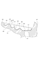
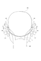
- Ears 100, 100 are part of head 200, and are each composed of auricles 101, 101 and parts such as eardrum, semicircular canal, cochlea, etc. existing inside head 200.
- the portions inside the auricles 101 and 101 of the head 200 are temporal heads 201 and 201, respectively.
- the auricles 101 and 101 protrude leftward or rightward from the temporal heads 201 and 201.
- the auricle 101 is formed in a shallow concave shape that is opened substantially forward as a whole so as to have an inner space 150, and the outer peripheral portion is located in the vicinity of the temporal region 201 that is continuous with the portion called the ear ring 102 and the ear ring 102. And a portion referred to as a ring leg 103.
- the inner part of the ear ring 102 is referred to as a concave boat-like fossa 104, and the lower half of the inner side of the boat-like fossa 104 is referred to as a convex anti-aural ring 105.
- a bifurcated convex portion exists continuously above the earring 105 above the earring 105, and an outer portion and an inner portion of the bifurcated portion are respectively the upper leg 106 and the earring. This is referred to as the lower leg 107.
- a portion between the upper ear ring 106 and the lower leg 107 is called a concave triangular fossa 108, and an inner portion of the anti-ear wheel 105 and the lower leg 107 is called a concave concha boat 109.
- the portion that continues to the lower side of the anti-aural ring 105 is a portion that is swollen to the side of the temporal region 201 and is called an anti-tragus 110.
- a portion on the side of the temporal head 201 facing the anti-tragus 110 is referred to as an tragus 111 bulging toward the anti-tragus 110, and a lower end continuous to the lower side of the ear ring 102 is referred to as an earlobe 112. .
- the outer ear canal 113a which is the entrance of the external auditory canal 113, is present between the antitragus 110 and the tragus 111, and the external auditory canal 113 communicates with the eardrum, the semicircular canal, and the like.
- a space surrounded by the antiauricle 105, the antiauricular leg 107, and the auricle leg 103, that is, a space on the front side of the concha boat 109 is referred to as an auricular cavity 114, and is the external auditory canal.
- 113 is communicated with the outer ear hole 113a.
- a space that opens continuously in the U-shape below the concha cavity 114 is a space referred to as an intercostal notch 115.
- the inner space 150 of the pinna 101 includes the concha cavity 114, the intercostal notch 115, and the space in the vicinity of the ear canal 113a of the ear canal 113, and the scaphoid fossa 104, the earring 105, the upper leg 106, and the lower leg. 107, a space including the space on the front side of the triangular fossa 108, the tragus 110 and the tragus 111.
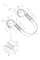
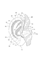
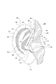
- the sound output device 1 has housings 2 and 2, ear-addressed parts 3 and 3, and a band 4.
- the casings 2 and 2 are connected by a band 4.
- the housing 2 is formed of, for example, a rubber material such as silicon, and includes an arrangement portion 5 that is continuous with the band 4, a cylindrical portion 6 that is connected to a portion of the arrangement portion 5 opposite to the band 4, and a cylinder And a detachable portion 7 that is detachably attached to the shape portion 6.
- Case bodies 8 and 8 are arranged inside the housings 2 and 2.
- the case body 8 is arranged at a position straddling the arrangement portion 5 of the housing 2 and one end portion of the cylindrical portion 6.
- the case body 8 includes a box-shaped case portion 8a opened on one side and a lid portion 8b for closing the case portion 8a.
- the case body 8 has an audio output hole 8c.
- Speakers 9 and 9 are arranged inside the case bodies 8 and 8, respectively.
- a dynamic driver unit may be employed.
- one or both of the casings 2 and 2 may be formed with various connection terminals such as a USB (Universal Serial Bus) terminal and a charging terminal, a voice input hole for a microphone, and the like.
- connection terminal When the connection terminal is formed in the housing 2, a circuit corresponding to the connection terminal is arranged inside the housing 2 in which the connection terminal is formed.
- the microphone 2 When the microphone 2 has a voice input hole for the microphone, the microphone is disposed inside the casing 2 in which the voice input hole is formed.
- a control board 10 is arranged together with a speaker 9, and a drive circuit for operating the speakers 9 and 9 and a communication circuit for wireless communication are formed on the control board 10. Therefore, the sound output device 1 receives a sound signal from another device such as a music player by wireless communication, converts the received sound signal and outputs it as sound from the speakers 9 and 9, and connects to the music player. Pairing processing such as authentication is possible. Examples of wireless communication for receiving an audio signal include Bluetooth (registered trademark), WiFi (Wireless Fidelity), NFC (Near Field Communication) as wireless communication for pairing processing such as connection authentication. It may be compatible with short-range wireless communication.
- the control board 10 is arranged inside the case body 8 together with the speaker 9.
- the speaker 9 and the control board 10 are disposed inside the case body 8 disposed inside the housing 2.
- the speaker 9 and the control board 10 are prevented from being damaged, and a good output state of sound from the speaker 9 can be ensured.
- a battery (battery) 11 is arranged together with a speaker 9 inside the other casing 2.
- the battery 11 may be a disposable type or a rechargeable type.
- the battery 11 is a disposable type, it is desirable that a part of the housing 2 can be opened and closed and the battery 11 can be replaced. Further, even when the battery 11 is a chargeable type, a part of the housing 2 may be opened and closed, and the battery 11 may be replaced.
- the battery 11 is disposed inside the case body 8 together with the speaker 9.
- the speaker 9 and the battery 11 are disposed inside the case body 8 disposed inside the housing 2, so that the speaker 9 and the battery 11 are protected by the case body 8.
- the speaker 9 and the battery 11 are prevented from being damaged, and a good output state of sound from the speaker 9 can be ensured.
- the power of the battery 11 is supplied to the speakers 9 and 9 and the control board 10 to operate the speakers 9 and 9 and the control board 10. Power is supplied from the battery 11 to the speaker 9 and the control board 10 disposed inside one housing 2 through the band 4.
- an electric wire for supplying electric power is arranged inside the band 4.
- a signal line for transmitting and receiving audio signals and other various signals is also provided inside the band 4, and the control board 10 disposed inside one housing 2 by the signal line is connected to the other signal line.
- An audio signal is output to the speaker 9 disposed inside the housing 2.
- a switch substrate 12 is attached to the outer surface of the case portion 8a of the case body 8 on which the control substrate 10 is disposed.
- a power switch 12a and volume control switches 12b and 12b are mounted on the outer surface of the switch substrate 12.
- the switch substrate 12 is connected to the control substrate 10.
- the power switch 12a is a switch for turning on and off the power
- the volume control switches 12b and 12b are switches for increasing the volume
- the other is a switch for decreasing the volume.
- An operation plate 13 is disposed on the outer surface side of the switch substrate 12.
- the operation plate 13 is provided with three operation pieces 13a, 13b, 13b, and the operation pieces 13a, 13b, 13b are positioned in contact with the power switch 12a and the volume control switches 12b, 12b, respectively.
- the switch substrate 12 and the operation plate 13 are disposed inside the housing 2 together with the case body 8.
- the switch substrate 12 and the operation plate 13 are, for example, directed downward or obliquely downward when the sound output device 1 is mounted on the ear 100.
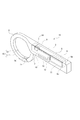
- the cylindrical part 6 is connected to the arrangement part 5 and is composed of a connection part 14 having a diameter reduced as it is separated from the arrangement part 5 and a bent part 15 having a uniform diameter.
- a part of the case body 8 is arranged inside the connecting part 14, and a speaker 9 is arranged inside a part of the case body 8 arranged inside the connecting part 14.
- the bent portion 15 is formed in a substantially semicircular arc shape.
- the tip of the bent portion 15 is provided as an attachment portion 15a.
- the detachable portion 7 is formed in a cylindrical shape having the same diameter as the bent portion 15 except for one end portion, and one end portion is opened and the other end portion (tip portion) is closed.
- the detachable part 7 is formed in, for example, an arc shape having the same curvature as the bent part 15.
- the detachable part 7 is formed of the same material as the cylindrical part 6, for example. However, the detachable part 7 may be formed of a material having a lower hardness than the cylindrical part 6.
- the attaching / detaching portion 7 is provided as an attached portion 7 a having one end that is slightly smaller in diameter than the bent portion 15.
- two openings 7b and 7b are formed at a position near the other end of the detachable portion 7.
- the openings 7 b and 7 b are penetrated in a direction orthogonal to the longitudinal direction of the detachable portion 7.
- the openings 7 b and 7 b are formed in a portion of the detachable portion 7 on the side facing the external auditory canal 113 in a state where the sound output device 1 is attached to the ear 100.
- the number of the openings 7b is arbitrary, and one may be formed, or three or more may be formed.
- the attaching / detaching portion 7 is attached to the bent portion 15 by fitting the attached portion 7a to the attaching portion 15a. Further, the detachable portion 7 can be detached from the bent portion 15 by being pulled out of the bent portion 15.
- an example in which the attached portion 7a is fitted to the attaching portion 15a and the attaching / detaching portion 7 is attached to the bent portion 15 is shown. It is also possible to form a recess in the detachable portion 7 and attach it to the bent portion 15 (see FIG. 6).
- an annular engagement protrusion 7c is provided at a position near one end of the detachable part 7
- an annular engagement recess 15b is formed at a position near the tip of the bent part 15, and the engagement protrusion 7c and the engagement recess 7 are formed. It is possible to adopt a configuration in which 15 b is engaged and the detachable portion 7 is attached to the bent portion 15.
- the detachable portion 7 is detachably attached to the bent portion 15, and various types having different shapes and sizes are used as the detachable portion 7.
- types having different lengths, types having different curvatures, and the like are used as the detachable part 7.
- the detachable part 7 having different lengths and curvatures are attached to the bent part 15 and the openings 7b and 7b are positioned at desired positions. Can be made.
- a type that becomes thicker as it goes to the tip or a type that gets thinner as it goes to the tip may be used as the detachable part 7.
- a type that becomes thicker toward the tip as the detachable portion 7, it becomes easier to listen to the sound output from the speaker 9.
- a type that becomes thinner toward the tip as the attaching / detaching portion 7, it is easy to hear external sound and sound leakage of the sound output from the speaker 9 can be suppressed.
- a type inclined toward the external auditory canal 113 can be used as the detachable part 7.
- this type of attachment / detachment unit 7 sound leakage from the sound output from the speaker 9 is suppressed and the sound can be easily heard.
- the bent portion 15 and the detachable portion 7 described above are configured as a sound guide hook 16 that guides the sound output from the speaker 9 in the internal space. Therefore, the internal space in the sound guide hook 16 is formed as a sound guide space 16 a that guides the sound output from the speaker 9. The sound guided through the sound guide space 16a is emitted from the openings 7b and 7b formed in the detachable portion 7 to the outside.
- the detachable portion 7 may be formed of a material (flexible material) that can be deformed (bent) and can maintain the deformed state.
- a material flexible material
- the attachment / detachment portion 7 is deformed into a desired state in a state where the sound output device 1 is attached to the ear 100, for example, the openings 7 b and 7 b are formed in the ear canal 113. Or the direction of the sound emitted from the openings 7b and 7b can be changed as necessary.
- the portion having the openings 7 b and 7 b of the sound guide hook 16 is provided as the detachable portion 7 that can be attached to and detached from the other portions of the sound guide hook 16. Accordingly, it is possible to replace the portion having the openings 7b and 7b of the sound guide hook 16 according to the size and shape of the ear 100, and to ensure a good listening state regardless of the size and shape of the ear 100. can do.
- the cylindrical portion 6 and the detachable portion 7 are made of a rubber material, and the sound guide hook 16 is made of a rubber material.
- the sound guide hook 16 is a portion to be attached to the root portion of the user's auricle 101, and the sound guide hook 16 is formed of a rubber material so that the sound guide hook 16 is attached to the ear 100.
- the sound guide hook 16 may be formed of a resin material, or may be formed of a multilayer structure.
- the sound guide hook 16 may have a two-layer structure having an inner peripheral portion and an outer peripheral portion, and may be configured by an inner layer of a metal material and an outer layer of a rubber material or a resin material.
- a metal material for the sound guide hook 16 it is possible to increase the rigidity of the sound guide hook 16, and in particular, by using aluminum or the like as the metal material, the sound output device 1 by reducing the weight of the sound guide hook 16. It is possible to ensure a good wearing feeling.
- the detachable portion 7 is formed of a material that can be deformed (bent) and is held in a deformed state, but both the cylindrical portion 6 and the detachable portion 7 are deformed (bent). It may be formed of a material that is capable of being held in a deformed state.
- the sound guide hook 16 is deformed into a desired state in a state where the sound output device 1 is attached to the ear 100, for example, an opening is formed. 7b and 7b can be brought close to the external auditory canal 113, and the direction of sound emitted from the openings 7b and 7b can be changed as necessary.
- the sound guide hook 16 can be deformed according to the shape and size of the ear 100 when the sound guide hook 16 is attached to the ear 100, the sound output device 1 can be stably attached to the ear 100. Can be secured.
- the ear-addressed portion 3 protrudes from the boundary portion between the placement portion 5 and the cylindrical portion 6 (see FIGS. 3 to 5).
- the ear-addressed part 3 is made of a material lower in level than the housing 2, for example, a rubber material, and is elastically deformable with respect to the cylindrical part 6.
- the ear-addressed portion 3 is formed in an arc shape having the same curvature as that of the sound guide hook 16 in a state where it is not elastically deformed, and is positioned in a state where the tip surface 3a faces the tip surface 16b of the sound guide hook 16 (FIG. 4 and FIG. 7).
- the ear addressing part 3 is formed integrally with the cylindrical part 6, for example.
- the ear-destined portion 3 is formed integrally with the cylindrical portion 6, it is not necessary to perform an operation of coupling the ear-destined portion 3 to the tubular portion 6, and the acoustic output device 1 is manufactured by reducing the manufacturing process. Cost can also be reduced.
- the ear-addressed portion 3 is elastically deformed with respect to the housing 2 to separate the tip surface 3a from the tip surface 16b of the sound guide hook 16 and form a large gap between the tip surface 3a and the tip surface 16b. (See FIG. 8).
- the band 4 is formed, for example, in a band shape from a rubber material, and is oriented so that the vertical direction is the width direction.
- the band 4 is formed integrally with the placement portions 5 and 5, for example.
- the sound output device 1 is provided with a pair of casings 2 and 2 and ear-addressed sections 3 and 3, and speakers 9 and 9 are disposed inside the casings 2 and 2, respectively.
- the sound output device 1 functions as a stereotype, the functionality of the sound output device 1 is improved, and high-quality sound can be heard.
- the speakers 9 and 9 are respectively disposed inside the housings 2 and 2, a good balance with respect to the ears 100 and 100 is ensured in terms of weight, and the ears 100 and 100 are kept in a stable state. Can be attached to.
- the control board 10 is disposed inside one housing 2, and the battery 11 is disposed inside the other housing 2. Therefore, the difference in weight between both sides of the sound output device 1 attached to the ears 100, 100 is reduced, a good weight balance is ensured, and the sound output device 1 is attached to the ear 100 in a stable state. be able to.
- the casings 2 and 2 are connected by the band 4, it is possible to send audio signals and supply current to both the speakers 9 and 9 by the band 4. Functionality can be ensured.
- casing 2 and 2 are connected by the band 4, the position with respect to the ear
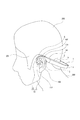
- the sound guide hooks 16, 16 are respectively located at the root portions of the auricles 101, 101 in the head 200, that is, at the boundary portion between the auricles 101, 101 and the temporal portions 201, 201 or its peripheral portion.
- the ear rings 102 are attached from the 102 side (upper side).
- the ear-addressed portions 3 and 3 are attached from the earlobe 112 side to the root portions of the auricles 101 and 101, that is, the boundary portions between the auricles 101 and 101 and the temporal portions 201 and 201 or their peripheral portions.
- the ear-addressed portions 3 and 3 are elastically deformable with respect to the sound guide hooks 16 and 16, the ear-addressed portions 3 and 3 are elastically deformed with respect to the sound guide hooks 16 and 16, and the tip surface 3a It is possible to attach the sound guide hooks 16 and 16 and the ear-addressing portions 3 and 3 to the ears 100 and 100 in a state where the clearance between the front end surface 16b and the front end surface 16b is large. Can be easily mounted.
- the sound output device 1 is in a state in which the ear contact portions 3 and 3 are elastically deformed so that the gap between the tip surface 3a and the tip surface 16b is larger than the gap before the ears 100 and 100 are attached. Attached to the ears 100, 100.
- the sound output device 1 presses the sound guide hook 16 and the ear-destined portion 3 against the root portion of the auricle 101, respectively.
- the sound output device 1 can be attached to the ear 100 in a stable state.
- the placement portions 5, 5 are the auricles 101 in the temporal regions 201, 201. , 101 (see FIG. 11).
- the detachable portions 7 and 7 are positioned in the inner spaces 150 and 150 of the auricles 101 and 101 in a state where the tip portions are not in contact with the auricles 101 and 101, respectively (see FIG. 12).
- the detachable portions 7 and 7 do not block the entire outer ear holes 113a and 113a, and the openings 7b and 7b are positioned in the vicinity of the outer ear holes 113a and 113a of the ear canals 113 and 113, respectively.
- the portion having 7b is not in contact with the ear 100.
- the portions having the openings 7 b and 7 b of the sound guide hook 16 are not in contact with the ear 100, so the openings 7 b and 7 b through which sound is emitted are provided. Since the part which has it will be in the state which is not contacted with the ear
- the openings 7b and 7b are formed on the side of the sound guide hook 16 facing the external auditory canal 113, the sound guided through the sound guide hook 16 is emitted from the openings 7b and 7b toward the ear canal 113, and the sound is emitted. I can hear it well.
- the openings 7b, 7b of the detachable portions 7, 7 in the sound guide hooks 16, 16 may be positioned in the concha cavities 114, 114, respectively. (See FIG. 13).
- the openings 7b and 7b of the detachable portions 7 and 7 may not be located in the external auditory canals 113 and 113 or the concha cavities 114 and 114, but are located in the inner spaces 150 and 150 of the auricles 101 and 101, respectively. In other words, it may be located away from the external auditory canals 113 and 113 and the concha cavity 114 and 114.
- the openings 7 b and 7 b of the detachable portions 7 and 7 may be located outside the inner spaces 150 and 150 of the auricles 101 and 101.
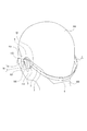
- the placement units 5, 5 are positioned in contact with the head 200 on the rear side of the auricles 101, 101 ( 9 to 11).
- the sound output device 1 is attached to the ears 100 and 100 while the sound guide hooks 16 and 16 are attached to the root portions of the auricles 101 and 101 and the placement portions 5 and 5 are in contact with the head 200. Therefore, the sound output device 1 can be attached to the ears 100 and 100 in a stable state.
- the openings 7b and 7b of the detachable portions 7 and 7 are located in the vicinity of the external auditory canals 113 and 113 or in the vicinity of the external ear holes 113a and 113a of the external auditory canals 113 and 113, the position where the sound is emitted is in the vicinity of the external auditory canals 113 and 113. It exists and can be heard well.
- the band 4 is positioned on the rear side of the head 200. At this time, since the band 4 is formed in a band shape in which the vertical direction is the width direction, the band 4 is unlikely to hang down due to gravity on the rear side of the head 200 and hardly touches the user's neck 300 (see FIG. 9).
- the band 4 is likely to be in a non-contact state with the neck 300 and the head 200, and a good wearing state of the sound output device 1 can be ensured.
- the power switch 12a or the volume control switch 12b is operated by pressing the operation pieces 13a, 13b, 13b from the outer surface side of the housing 2. , 12b are operated to turn on / off the power or change the volume.
- the power switch 12a is operated and the power is turned on, the speaker 9, 9 is opened through the sound output holes 8c, 8c formed in the case body 8 and the sound guide spaces 16a, 16a of the sound guide hooks 16, 16. A sound is emitted from 7b, 7b,...
- the acoustic output device 1A shown below is different from the above-described acoustic output device 1 only in that the number of casings and ear-addressed portions are different and no band is provided and the internal structure of the casing is different. Therefore, only the portions that are different from the sound output device 1 will be described in detail, and the other portions will be denoted by the same reference numerals as the same portions in the sound output device 1 and the description thereof will be omitted. .
- the acoustic output device 1A has one housing 2 and one ear-addressed portion 3.
- a case body 8 is disposed inside the housing 2, and a speaker 9, a control board 10, and a battery 11 are disposed inside the case body 8.
- a switch substrate 12 is attached to the case body 8, and an operation plate 13 is disposed on the outer surface side of the switch substrate 12. Either the control board 10 or the battery 11 may be arranged on the speaker 9 side. The power of the battery 11 is supplied to the speaker 9 and the control board 10, and the speaker 9 and the control board 10 are driven.
- the housing 2 may be formed with various connection terminals such as a USB (Universal Serial Bus) terminal and a charging terminal, a voice input hole for a microphone, and the like.
- connection terminal When the connection terminal is formed in the housing 2, a circuit corresponding to the connection terminal is arranged inside the housing 2, and when the microphone 2 has a voice input hole for the microphone, the housing 2 A microphone is disposed in the interior of 2.
- USB Universal Serial Bus
- the sound guide hook 16 has the ear ring 102 side (upper side) at the root portion of the left or right auricle 101 of the head 200, that is, the boundary portion between the auricle 101 and the temporal portion 201 or its peripheral portion. ) And the ear-addressed portion 3 is attached to the root portion of the auricle 101, that is, the boundary portion between the auricle 101 and the temporal region 201 or its peripheral portion from the earlobe 112 side (lower side).
- the placement portion 5 is pressed against the rear portion of the auricle 101 in the temporal region 201.
- the detachable portion 7 is positioned in the inner space 150 of the auricle 101 with the tip portion not contacting the auricle 101.
- the attaching / detaching portion 7 is set so as not to block the entire outer ear hole 113 a, the opening 7 b is positioned in the vicinity of the outer ear hole 113 a of the ear canal 113, and the portion having the openings 7 b and 7 b of the sound guide hook 16 is not in contact with the ear 100. State.
- the part having the openings 7 b and 7 b of the sound guide hook 16 is located in the concha cavity 114 or the external auditory canal 113 in the inner space 150 of the auricle 101.
- the portion having the openings 7 b and 7 b of the sound guide hook 16 may not be located in the concha cavity 114 or the external auditory canal 113, and from the external auditory canal 113 and the concha cavity 114 as long as it is located in the inner space 150. It may be located remotely.
- the portion having the openings 7 b and 7 b of the sound guide hook 16 may be positioned outside the inner space 150 of the auricle 101.
- the housing 2 and the ear-addressed portion 3 are provided one by one, and the battery 11 is disposed inside the housing 2.
- the burden on the user when it is attached to the ear 100 is reduced, and a good wearing feeling of the sound output device 1A can be ensured.
- the sound output device 1 or 1A that receives an audio signal from another device such as a music player by wireless communication has been shown. It is also possible to configure the sound output device 1B to which a signal is input (see FIG. 15).
- the sound output device 1B may be a type having two speakers 9 and 9 like the sound output device 1, or may be a type having one speaker 9 like the sound output device 1A.
- a sound output device 1B having two speakers 9 and 9 will be described as an example.
- the sound output device 1B includes housings 2 and 2, ear-addressed portions 3 and 3, and a band 4.
- a cable 17 is connected to one housing 2.
- One end of the cable 17 is connected to the speaker 9 and the switch substrate 12 separately.
- a connector 18 is provided at the other end of the cable 17, and the connector 18 is connected to an output terminal of another device such as a music player.
- the two speakers 9 and 9 are connected to each other by a pair of casings 2 and 2 and electric wires arranged inside the band 4.
- the cable 17 may be connected to the band 4 or the ear-addressed portion 3 and connected to the speaker 9 and the switch substrate 12 separately.
- the speaker 9 is disposed inside the case body 8, the switch substrate 12 is attached to the outer surface of the case body 8, and the operation plate 13 is disposed on the outer surface side of the switch substrate 12.
- the control board 10 and the battery 11 are not arranged inside the housings 2 and 2, and the power supply to the sound output device 1 ⁇ / b> B and the input of the audio signal are input from other devices such as a music player via the cable 17. Done.
- an audio signal is input through a wired connection, and the control board 10 and the battery 11 are not disposed inside the housings 2 and 2, so that the weight can be reduced.
- the internal structure can be simplified.
- the weight is reduced as described above, an excessive load is not applied to the ear 100 when the ear 100 is worn, and a good wearing state with no sense of incongruity to the ear 100 is provided. Can be secured.
- the sound output devices 1, 1 ⁇ / b> A, 1 ⁇ / b> B include the speaker 9, the housing 2, and the ear-addressed portion 3, and the housing 2 is provided with the sound guide hook 16 having the opening 7 b.
- the lead hook 16 is attached to the root portion of the auricle 101 from the auricle 102 side, and the ear-addressed portion 3 is attached to the root portion of the auricle 101 from the earlobe 112 side.
- the sound guide hook 16 is attached to the root portion of the auricle 101 from the ear ring 102 side, and the ear contact portion 3 is attached to the root portion of the auricle 101 from the earlobe 112 side, and the sound guide hook 16 and the ear contact portion 3 are attached.
- the sound guide hook 16 and the ear-addressed portion 3 are formed in a continuous arc shape having substantially the same curvature, the sound guide hook 16 and the ear-addressed portion 3 are substantially matched to the shape of the root portion of the auricle 101. It is formed in a shape, and it is possible to ensure a wearing state without a sense of incongruity to the ear 100.
- the ear-addressed portion 3 is formed of a material having a lower hardness than the sound guide hook 16, the sound guide hook 16 attached to the root portion of the auricle 101 from the auricle 102 side has a high hardness and the root of the auricle 101. The hardness of the ear-addressed portion 3 attached to the portion from the earlobe 112 side is lowered.
- the sound guide hook 16 is not easily deformed, and an excessive load is not applied to the root portion of the auricle 101 from the ear destination portion 3. A stable and good wearing state of the output device 1, 1A, 1B to the ear 100 can be ensured.
- the sound output from the speaker 9 is transmitted to the user via the sound guide hook 16 and the tip of the sound guide hook 16 contacts the ear 100. Since it is mounted in a state where it is not attached, it is possible to ensure good recognition between the sound output from the speaker 9 and the external sound, and to reduce the occurrence of a sense of incongruity in the mounted state.
- the sound output from the speaker 9 is recognized by being guided through the sound guiding space 16a of the sound guiding hook 16, and the vibration is transmitted to the earbone to recognize the sound. Since the bone conduction method is not performed, the reproducibility of the low range in the voice region is increased, and it is easy to hear the low tone.
- the tip of the sound guide hook 16 does not contact the ear 100 and the external auditory canal 113 is not blocked, good reproducibility of low sound can be ensured and the head-related transfer function hardly changes, so that external sounds can be recognized correctly. can do.
- the openings 7 b and 7 b of the sound guide hook 16 are positioned in the inner space 150 of the auricle 101. Since 7b is located close to the external auditory canal 113, it is possible to ensure good recognition between the sound output from the speaker 9 and the external sound.
- the present technology can be configured as follows.
- a speaker that outputs audio A housing in which an internal space has a sound guide hook formed as a sound guide space for guiding sound output from the speaker and the speaker is disposed inside; An ear-addressed portion provided continuously in the housing; The sound guide hook is formed with an opening for emitting sound toward the ear, The sound guide hook is attached to the root part of the auricle from the side of the auricle, The sound output device in which the ear-addressed portion is attached to the base portion of the pinna from the earlobe side.
- a case body is arranged inside the housing,
- a pair of each of the housing and the ear-addressed portion is provided, The sound output device according to any one of (1) to (10), wherein the speakers are respectively disposed inside the pair of housings.
- a control board is disposed inside one of the casings, The acoustic output device according to (11), wherein a battery is disposed inside the other casing.
- Each of the housing and the ear-addressed portion is provided, The acoustic output device according to any one of (1) to (10), wherein a battery is disposed inside the housing.
Landscapes
- Engineering & Computer Science (AREA)
- Physics & Mathematics (AREA)
- Acoustics & Sound (AREA)
- Signal Processing (AREA)
- Health & Medical Sciences (AREA)
- Otolaryngology (AREA)
- Manufacturing & Machinery (AREA)
- Headphones And Earphones (AREA)
Abstract
Description
先ず、音響出力装置が装着される耳の構造について説明する(図1及び図2参照)。
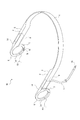
次に、音響出力装置の構成について説明する(図3乃至図5参照)。
以下に、音響出力装置1の耳100、100に対する装着状態について説明する(図9乃至図13参照)。
上記には、それぞれ一対の筐体2、2と耳宛部3、3とバンド4を有する音響出力装置1の例を示したが、例えば、以下のように、一つずつの筐体2と耳宛部3を有する音響出力装置1Aを設けることも可能である(図14参照)。
以上に記載した通り、音響出力装置1、1A、1Bにあっては、スピーカー9と筐体2と耳宛部3を備え、筐体2に開口7bを有する音導フック16が設けられ、音導フック16が耳介101の根元部分に耳輪102側から装着され、耳宛部3が耳介101の根元部分に耳垂112側から装着される。
本技術は、以下のような構成にすることができる。
音声を出力するスピーカーと、
内部の空間が前記スピーカーから出力される音声を導く音導空間として形成された音導フックを有すると共に内部に前記スピーカーが配置された筐体と、
前記筐体に連続して設けられた耳宛部とを備え、
前記音導フックには音声を耳へ向けて発する開口が形成され、
前記音導フックが耳介の根元部分に耳輪側から装着され、
前記耳宛部が耳介の根元部分に耳垂側から装着される
音響出力装置。
前記開口が前記耳介の内側空間に位置される
前記(1)に記載の音響出力装置。
前記開口が耳甲介腔に位置される
前記(2)に記載の音響出力装置。
前記開口が前記音導フックにおける外耳道に対向する側に形成された
前記(1)から前記(3)の何れかに記載の音響出力装置。
前記音導フックの前記開口を有する部分が前記音導フックの他の部分に対して着脱可能な着脱部として設けられた
前記(1)から前記(4)の何れかに記載の音響出力装置。
前記音導フックと前記耳宛部が連続する略同じ曲率の円弧状に形成された
前記(1)から前記(5)の何れかに記載の音響出力装置。
前記耳宛部が前記音導フックより硬度の低い材料によって形成された
前記(1)から前記(6)の何れかに記載の音響出力装置。
前記耳宛部が前記音導フックに対して弾性変形可能にされた
前記(1)から前記(7)の何れかに記載の音響出力装置。
耳に装着された状態において前記音導フックの前記開口を有する部分が耳に非接触の状態とされる
前記(1)から前記(8)の何れかに記載の音響出力装置。
前記筐体の内部にケース体が配置され、
前記ケース体の内部に前記スピーカーと前記スピーカーを制御する制御基板とが配置された
前記(1)から前記(9)の何れかに記載の音響出力装置。
前記筐体と前記耳宛部がそれぞれ一対ずつ設けられ、
前記一対の筐体の内部にそれぞれ前記スピーカーが配置された
前記(1)から前記(10)の何れかに記載の音響出力装置。
一方の前記筐体の内部に制御基板が配置され、
他方の前記筐体の内部に電池が配置された
前記(11)に記載の音響出力装置。
前記一対の筐体を連結するバンドが設けられた
前記(11)又は前記(12)に記載の音響出力装置。
前記バンドが帯状に形成された
前記(13)に記載の音響出力装置。
前記筐体と前記耳宛部がそれぞれ一つずつ設けられ、
前記筐体の内部に電池が配置された
前記(1)から前記(10)の何れかに記載の音響出力装置。
前記筐体の一部が耳介の後側において側頭部に接触された状態で位置される
前記(1)から前記(15)の何れかに記載の音響出力装置。
前記音導フックが屈曲可能にされた
前記(1)から前記(16)の何れかに記載の音響出力装置。
Claims (17)
- 音声を出力するスピーカーと、
内部の空間が前記スピーカーから出力される音声を導く音導空間として形成された音導フックを有すると共に内部に前記スピーカーが配置された筐体と、
前記筐体に連続して設けられた耳宛部とを備え、
前記音導フックには音声を耳へ向けて発する開口が形成され、
前記音導フックが耳介の根元部分に耳輪側から装着され、
前記耳宛部が耳介の根元部分に耳垂側から装着される
音響出力装置。 - 前記開口が前記耳介の内側空間に位置される
請求項1に記載の音響出力装置。 - 前記開口が耳甲介腔に位置される
請求項2に記載の音響出力装置。 - 前記開口が前記音導フックにおける外耳道に対向する側に形成された
請求項1に記載の音響出力装置。 - 前記音導フックの前記開口を有する部分が前記音導フックの他の部分に対して着脱可能な着脱部として設けられた
請求項1に記載の音響出力装置。 - 前記音導フックと前記耳宛部が連続する略同じ曲率の円弧状に形成された
請求項1に記載の音響出力装置。 - 前記耳宛部が前記音導フックより硬度の低い材料によって形成された
請求項1に記載の音響出力装置。 - 前記耳宛部が前記音導フックに対して弾性変形可能にされた
請求項1に記載の音響出力装置。 - 耳に装着された状態において前記音導フックの前記開口を有する部分が耳に非接触の状態とされる
請求項1に記載の音響出力装置。 - 前記筐体の内部にケース体が配置され、
前記ケース体の内部に前記スピーカーと前記スピーカーを制御する制御基板とが配置された
請求項1に記載の音響出力装置。 - 前記筐体と前記耳宛部がそれぞれ一対ずつ設けられ、
前記一対の筐体の内部にそれぞれ前記スピーカーが配置された
請求項1に記載の音響出力装置。 - 一方の前記筐体の内部に制御基板が配置され、
他方の前記筐体の内部に電池が配置された
請求項11に記載の音響出力装置。 - 前記一対の筐体を連結するバンドが設けられた
請求項11に記載の音響出力装置。 - 前記バンドが帯状に形成された
請求項13に記載の音響出力装置。 - 前記筐体と前記耳宛部がそれぞれ一つずつ設けられ、
前記筐体の内部に電池が配置された
請求項1に記載の音響出力装置。 - 前記筐体の一部が耳介の後側において側頭部に接触された状態で位置される
請求項1に記載の音響出力装置。 - 前記音導フックが屈曲可能にされた
請求項1に記載の音響出力装置。
Priority Applications (4)
| Application Number | Priority Date | Filing Date | Title |
|---|---|---|---|
| CN201680080051.7A CN108496373B (zh) | 2016-02-01 | 2016-12-27 | 声音输出装置 |
| JP2017565435A JP6911769B2 (ja) | 2016-02-01 | 2016-12-27 | 音響出力装置 |
| EP16889451.7A EP3413581B1 (en) | 2016-02-01 | 2016-12-27 | Sound output device |
| US16/069,794 US11445287B2 (en) | 2016-02-01 | 2016-12-27 | Sound output device |
Applications Claiming Priority (2)
| Application Number | Priority Date | Filing Date | Title |
|---|---|---|---|
| JP2016017271 | 2016-02-01 | ||
| JP2016-017271 | 2016-08-11 |
Publications (1)
| Publication Number | Publication Date |
|---|---|
| WO2017134968A1 true WO2017134968A1 (ja) | 2017-08-10 |
Family
ID=59501100
Family Applications (1)
| Application Number | Title | Priority Date | Filing Date |
|---|---|---|---|
| PCT/JP2016/088981 Ceased WO2017134968A1 (ja) | 2016-02-01 | 2016-12-27 | 音響出力装置 |
Country Status (5)
| Country | Link |
|---|---|
| US (1) | US11445287B2 (ja) |
| EP (1) | EP3413581B1 (ja) |
| JP (1) | JP6911769B2 (ja) |
| CN (1) | CN108496373B (ja) |
| WO (1) | WO2017134968A1 (ja) |
Cited By (1)
| Publication number | Priority date | Publication date | Assignee | Title |
|---|---|---|---|---|
| JPWO2021261084A1 (ja) * | 2020-06-25 | 2021-12-30 |
Families Citing this family (2)
| Publication number | Priority date | Publication date | Assignee | Title |
|---|---|---|---|---|
| CN113016193B (zh) * | 2018-11-25 | 2024-02-23 | 株式会社慕悟 | 耳机 |
| GB2595448B (en) | 2020-05-18 | 2022-10-19 | Dyson Technology Ltd | Headband for a wearable electronic device |
Citations (10)
| Publication number | Priority date | Publication date | Assignee | Title |
|---|---|---|---|---|
| JPH04101600A (ja) * | 1990-08-21 | 1992-04-03 | Sony Corp | 電気音響変換器及び音響再生システム |
| JPH0576200U (ja) * | 1992-03-16 | 1993-10-15 | ソニー株式会社 | 可変電気素子のカバー |
| JPH0580098U (ja) * | 1992-03-27 | 1993-10-29 | リオン株式会社 | 補聴器保持装置 |
| JPH1023599A (ja) * | 1996-07-03 | 1998-01-23 | Piolax Inc | 耳かけ式補聴器 |
| JP2001120590A (ja) * | 1999-10-29 | 2001-05-08 | Mimii Denshi Kk | 耳せん |
| JP2013115800A (ja) * | 2011-12-01 | 2013-06-10 | Goldendance Co Ltd | 耳掛け型補聴器 |
| JP2013534115A (ja) * | 2010-07-09 | 2013-08-29 | シュアー アクイジッション ホールディングス インコーポレイテッド | イヤホン組付体 |
| WO2014041611A1 (ja) * | 2012-09-11 | 2014-03-20 | パイオニア株式会社 | 電子機器 |
| WO2015037317A1 (ja) * | 2013-09-13 | 2015-03-19 | エムケー電子株式会社 | 集音器 |
| JP2015207956A (ja) * | 2014-04-23 | 2015-11-19 | 丸山 誠二 | 耳近接スピーカ装置 |
Family Cites Families (15)
| Publication number | Priority date | Publication date | Assignee | Title |
|---|---|---|---|---|
| US6009183A (en) * | 1998-06-30 | 1999-12-28 | Resound Corporation | Ambidextrous sound delivery tube system |
| US8482488B2 (en) * | 2004-12-22 | 2013-07-09 | Oakley, Inc. | Data input management system for wearable electronically enabled interface |
| US20110170723A1 (en) * | 2005-08-29 | 2011-07-14 | William Ryann | Earpiece headset assembly |
| US8452039B2 (en) | 2006-05-03 | 2013-05-28 | Mad Catz, Inc | Wearable personal sound delivery apparatus |
| KR100955033B1 (ko) * | 2009-02-10 | 2010-04-26 | 지디텍 주식회사 | 귀걸이형 무선스피커장치 |
| CN201426167Y (zh) * | 2009-04-17 | 2010-03-17 | 富祐鸿科技股份有限公司 | 具导音管的开放式结构耳机 |
| EP2469890B1 (en) * | 2010-12-23 | 2015-06-24 | GN ReSound A/S | A BTE hearing aid with an elongated securing member |
| JP6026235B2 (ja) * | 2011-12-22 | 2016-11-16 | 株式会社ディーアンドエムホールディングス | ネックバンド型イヤーホン |
| TW201408992A (zh) | 2012-08-21 | 2014-03-01 | Hon Hai Prec Ind Co Ltd | 移動終端、雲伺服器及熱門景點識別方法 |
| EP2974360B1 (en) * | 2013-03-14 | 2019-09-25 | Harman International Industries, Incorporated | Behind the ear earphone |
| CN109474864A (zh) * | 2014-10-30 | 2019-03-15 | 索尼公司 | 声音输出装置 |
| WO2016067754A1 (ja) * | 2014-10-30 | 2016-05-06 | ソニー株式会社 | 音響出力装置 |
| US10063958B2 (en) * | 2014-11-07 | 2018-08-28 | Microsoft Technology Licensing, Llc | Earpiece attachment devices |
| US20160134958A1 (en) * | 2014-11-07 | 2016-05-12 | Microsoft Technology Licensing, Llc | Sound transmission systems and devices having earpieces |
| EP3383061A4 (en) * | 2015-11-25 | 2018-11-14 | Sony Corporation | Sound collecting device |
-
2016
- 2016-12-27 EP EP16889451.7A patent/EP3413581B1/en active Active
- 2016-12-27 WO PCT/JP2016/088981 patent/WO2017134968A1/ja not_active Ceased
- 2016-12-27 US US16/069,794 patent/US11445287B2/en active Active
- 2016-12-27 CN CN201680080051.7A patent/CN108496373B/zh active Active
- 2016-12-27 JP JP2017565435A patent/JP6911769B2/ja active Active
Patent Citations (10)
| Publication number | Priority date | Publication date | Assignee | Title |
|---|---|---|---|---|
| JPH04101600A (ja) * | 1990-08-21 | 1992-04-03 | Sony Corp | 電気音響変換器及び音響再生システム |
| JPH0576200U (ja) * | 1992-03-16 | 1993-10-15 | ソニー株式会社 | 可変電気素子のカバー |
| JPH0580098U (ja) * | 1992-03-27 | 1993-10-29 | リオン株式会社 | 補聴器保持装置 |
| JPH1023599A (ja) * | 1996-07-03 | 1998-01-23 | Piolax Inc | 耳かけ式補聴器 |
| JP2001120590A (ja) * | 1999-10-29 | 2001-05-08 | Mimii Denshi Kk | 耳せん |
| JP2013534115A (ja) * | 2010-07-09 | 2013-08-29 | シュアー アクイジッション ホールディングス インコーポレイテッド | イヤホン組付体 |
| JP2013115800A (ja) * | 2011-12-01 | 2013-06-10 | Goldendance Co Ltd | 耳掛け型補聴器 |
| WO2014041611A1 (ja) * | 2012-09-11 | 2014-03-20 | パイオニア株式会社 | 電子機器 |
| WO2015037317A1 (ja) * | 2013-09-13 | 2015-03-19 | エムケー電子株式会社 | 集音器 |
| JP2015207956A (ja) * | 2014-04-23 | 2015-11-19 | 丸山 誠二 | 耳近接スピーカ装置 |
Non-Patent Citations (1)
| Title |
|---|
| See also references of EP3413581A4 * |
Cited By (3)
| Publication number | Priority date | Publication date | Assignee | Title |
|---|---|---|---|---|
| JPWO2021261084A1 (ja) * | 2020-06-25 | 2021-12-30 | ||
| US12375843B2 (en) | 2020-06-25 | 2025-07-29 | Sony Group Corporation | Sound output device |
| JP7732455B2 (ja) | 2020-06-25 | 2025-09-02 | ソニーグループ株式会社 | 音響出力装置 |
Also Published As
| Publication number | Publication date |
|---|---|
| EP3413581A4 (en) | 2019-01-02 |
| US11445287B2 (en) | 2022-09-13 |
| EP3413581A1 (en) | 2018-12-12 |
| JPWO2017134968A1 (ja) | 2018-11-22 |
| CN108496373A (zh) | 2018-09-04 |
| JP6911769B2 (ja) | 2021-07-28 |
| US20190037296A1 (en) | 2019-01-31 |
| CN108496373B (zh) | 2020-08-21 |
| EP3413581B1 (en) | 2020-10-28 |
Similar Documents
| Publication | Publication Date | Title |
|---|---|---|
| JP6631530B2 (ja) | 音響出力装置 | |
| CN112153510A (zh) | Tws骨传导耳机 | |
| JP7626794B2 (ja) | 音響出力装置 | |
| EP3509319B1 (en) | Sound output device | |
| JP2019193000A (ja) | イヤモールド、イヤホン、及び軟骨伝導補聴器 | |
| JP6911769B2 (ja) | 音響出力装置 | |
| KR101694706B1 (ko) | 이어셋 | |
| US20230300507A1 (en) | Sound output device | |
| JP6431569B1 (ja) | イヤホン | |
| CN212752573U (zh) | 耳机、耳机密封套 | |
| WO2020116253A1 (ja) | 電気音響変換器及び音響機器 | |
| CN113016193B (zh) | 耳机 | |
| BR112019003531B1 (pt) | Aparelho para emissão de som | |
| BR112019014899B1 (pt) | Dispositivo de saída de som |
Legal Events
| Date | Code | Title | Description |
|---|---|---|---|
| 121 | Ep: the epo has been informed by wipo that ep was designated in this application |
Ref document number: 16889451 Country of ref document: EP Kind code of ref document: A1 |
|
| ENP | Entry into the national phase |
Ref document number: 2017565435 Country of ref document: JP Kind code of ref document: A |
|
| NENP | Non-entry into the national phase |
Ref country code: DE |
|
| WWE | Wipo information: entry into national phase |
Ref document number: 2016889451 Country of ref document: EP |
|
| ENP | Entry into the national phase |
Ref document number: 2016889451 Country of ref document: EP Effective date: 20180903 |