WO2017134977A1 - 陰嚢シート - Google Patents
陰嚢シート Download PDFInfo
- Publication number
- WO2017134977A1 WO2017134977A1 PCT/JP2017/000196 JP2017000196W WO2017134977A1 WO 2017134977 A1 WO2017134977 A1 WO 2017134977A1 JP 2017000196 W JP2017000196 W JP 2017000196W WO 2017134977 A1 WO2017134977 A1 WO 2017134977A1
- Authority
- WO
- WIPO (PCT)
- Prior art keywords
- scrotum
- sheet
- scrotal
- temperature
- material layer
- Prior art date
- Legal status (The legal status is an assumption and is not a legal conclusion. Google has not performed a legal analysis and makes no representation as to the accuracy of the status listed.)
- Ceased
Links
Images




Classifications
-
- A—HUMAN NECESSITIES
- A61—MEDICAL OR VETERINARY SCIENCE; HYGIENE
- A61F—FILTERS IMPLANTABLE INTO BLOOD VESSELS; PROSTHESES; DEVICES PROVIDING PATENCY TO, OR PREVENTING COLLAPSING OF, TUBULAR STRUCTURES OF THE BODY, e.g. STENTS; ORTHOPAEDIC, NURSING OR CONTRACEPTIVE DEVICES; FOMENTATION; TREATMENT OR PROTECTION OF EYES OR EARS; BANDAGES, DRESSINGS OR ABSORBENT PADS; FIRST-AID KITS
- A61F7/00—Heating or cooling appliances for medical or therapeutic treatment of the human body
- A61F7/02—Compresses or poultices for effecting heating or cooling
-
- A—HUMAN NECESSITIES
- A61—MEDICAL OR VETERINARY SCIENCE; HYGIENE
- A61F—FILTERS IMPLANTABLE INTO BLOOD VESSELS; PROSTHESES; DEVICES PROVIDING PATENCY TO, OR PREVENTING COLLAPSING OF, TUBULAR STRUCTURES OF THE BODY, e.g. STENTS; ORTHOPAEDIC, NURSING OR CONTRACEPTIVE DEVICES; FOMENTATION; TREATMENT OR PROTECTION OF EYES OR EARS; BANDAGES, DRESSINGS OR ABSORBENT PADS; FIRST-AID KITS
- A61F7/00—Heating or cooling appliances for medical or therapeutic treatment of the human body
- A61F7/02—Compresses or poultices for effecting heating or cooling
- A61F7/03—Compresses or poultices for effecting heating or cooling thermophore, i.e. self-heating, e.g. using a chemical reaction
-
- A—HUMAN NECESSITIES
- A01—AGRICULTURE; FORESTRY; ANIMAL HUSBANDRY; HUNTING; TRAPPING; FISHING
- A01N—PRESERVATION OF BODIES OF HUMANS OR ANIMALS OR PLANTS OR PARTS THEREOF; BIOCIDES, e.g. AS DISINFECTANTS, AS PESTICIDES OR AS HERBICIDES; PEST REPELLANTS OR ATTRACTANTS; PLANT GROWTH REGULATORS
- A01N37/00—Biocides, pest repellants or attractants, or plant growth regulators containing organic compounds containing a carbon atom having three bonds to hetero atoms with at the most two bonds to halogen, e.g. carboxylic acids
- A01N37/36—Biocides, pest repellants or attractants, or plant growth regulators containing organic compounds containing a carbon atom having three bonds to hetero atoms with at the most two bonds to halogen, e.g. carboxylic acids containing at least one carboxylic group or a thio analogue, or a derivative thereof, and a singly bound oxygen or sulfur atom attached to the same carbon skeleton, this oxygen or sulfur atom not being a member of a carboxylic group or of a thio analogue, or of a derivative thereof, e.g. hydroxy-carboxylic acids
- A01N37/38—Biocides, pest repellants or attractants, or plant growth regulators containing organic compounds containing a carbon atom having three bonds to hetero atoms with at the most two bonds to halogen, e.g. carboxylic acids containing at least one carboxylic group or a thio analogue, or a derivative thereof, and a singly bound oxygen or sulfur atom attached to the same carbon skeleton, this oxygen or sulfur atom not being a member of a carboxylic group or of a thio analogue, or of a derivative thereof, e.g. hydroxy-carboxylic acids having at least one oxygen or sulfur atom attached to an aromatic ring system
- A01N37/40—Biocides, pest repellants or attractants, or plant growth regulators containing organic compounds containing a carbon atom having three bonds to hetero atoms with at the most two bonds to halogen, e.g. carboxylic acids containing at least one carboxylic group or a thio analogue, or a derivative thereof, and a singly bound oxygen or sulfur atom attached to the same carbon skeleton, this oxygen or sulfur atom not being a member of a carboxylic group or of a thio analogue, or of a derivative thereof, e.g. hydroxy-carboxylic acids having at least one oxygen or sulfur atom attached to an aromatic ring system having at least one carboxylic group or a thio analogue, or a derivative thereof, and one oxygen or sulfur atom attached to the same aromatic ring system
-
- A—HUMAN NECESSITIES
- A61—MEDICAL OR VETERINARY SCIENCE; HYGIENE
- A61K—PREPARATIONS FOR MEDICAL, DENTAL OR TOILETRY PURPOSES
- A61K31/00—Medicinal preparations containing organic active ingredients
- A61K31/045—Hydroxy compounds, e.g. alcohols; Salts thereof, e.g. alcoholates
-
- A—HUMAN NECESSITIES
- A61—MEDICAL OR VETERINARY SCIENCE; HYGIENE
- A61F—FILTERS IMPLANTABLE INTO BLOOD VESSELS; PROSTHESES; DEVICES PROVIDING PATENCY TO, OR PREVENTING COLLAPSING OF, TUBULAR STRUCTURES OF THE BODY, e.g. STENTS; ORTHOPAEDIC, NURSING OR CONTRACEPTIVE DEVICES; FOMENTATION; TREATMENT OR PROTECTION OF EYES OR EARS; BANDAGES, DRESSINGS OR ABSORBENT PADS; FIRST-AID KITS
- A61F7/00—Heating or cooling appliances for medical or therapeutic treatment of the human body
- A61F2007/0001—Body part
- A61F2007/0048—Genitals
-
- A—HUMAN NECESSITIES
- A61—MEDICAL OR VETERINARY SCIENCE; HYGIENE
- A61F—FILTERS IMPLANTABLE INTO BLOOD VESSELS; PROSTHESES; DEVICES PROVIDING PATENCY TO, OR PREVENTING COLLAPSING OF, TUBULAR STRUCTURES OF THE BODY, e.g. STENTS; ORTHOPAEDIC, NURSING OR CONTRACEPTIVE DEVICES; FOMENTATION; TREATMENT OR PROTECTION OF EYES OR EARS; BANDAGES, DRESSINGS OR ABSORBENT PADS; FIRST-AID KITS
- A61F7/00—Heating or cooling appliances for medical or therapeutic treatment of the human body
- A61F7/02—Compresses or poultices for effecting heating or cooling
- A61F2007/0225—Compresses or poultices for effecting heating or cooling connected to the body or a part thereof
- A61F2007/0226—Compresses or poultices for effecting heating or cooling connected to the body or a part thereof adhesive, self-sticking
-
- A—HUMAN NECESSITIES
- A61—MEDICAL OR VETERINARY SCIENCE; HYGIENE
- A61F—FILTERS IMPLANTABLE INTO BLOOD VESSELS; PROSTHESES; DEVICES PROVIDING PATENCY TO, OR PREVENTING COLLAPSING OF, TUBULAR STRUCTURES OF THE BODY, e.g. STENTS; ORTHOPAEDIC, NURSING OR CONTRACEPTIVE DEVICES; FOMENTATION; TREATMENT OR PROTECTION OF EYES OR EARS; BANDAGES, DRESSINGS OR ABSORBENT PADS; FIRST-AID KITS
- A61F7/00—Heating or cooling appliances for medical or therapeutic treatment of the human body
- A61F7/02—Compresses or poultices for effecting heating or cooling
- A61F2007/0244—Compresses or poultices for effecting heating or cooling with layers
-
- A—HUMAN NECESSITIES
- A61—MEDICAL OR VETERINARY SCIENCE; HYGIENE
- A61F—FILTERS IMPLANTABLE INTO BLOOD VESSELS; PROSTHESES; DEVICES PROVIDING PATENCY TO, OR PREVENTING COLLAPSING OF, TUBULAR STRUCTURES OF THE BODY, e.g. STENTS; ORTHOPAEDIC, NURSING OR CONTRACEPTIVE DEVICES; FOMENTATION; TREATMENT OR PROTECTION OF EYES OR EARS; BANDAGES, DRESSINGS OR ABSORBENT PADS; FIRST-AID KITS
- A61F7/00—Heating or cooling appliances for medical or therapeutic treatment of the human body
- A61F7/02—Compresses or poultices for effecting heating or cooling
- A61F2007/0261—Compresses or poultices for effecting heating or cooling medicated
-
- A—HUMAN NECESSITIES
- A61—MEDICAL OR VETERINARY SCIENCE; HYGIENE
- A61F—FILTERS IMPLANTABLE INTO BLOOD VESSELS; PROSTHESES; DEVICES PROVIDING PATENCY TO, OR PREVENTING COLLAPSING OF, TUBULAR STRUCTURES OF THE BODY, e.g. STENTS; ORTHOPAEDIC, NURSING OR CONTRACEPTIVE DEVICES; FOMENTATION; TREATMENT OR PROTECTION OF EYES OR EARS; BANDAGES, DRESSINGS OR ABSORBENT PADS; FIRST-AID KITS
- A61F7/00—Heating or cooling appliances for medical or therapeutic treatment of the human body
- A61F7/02—Compresses or poultices for effecting heating or cooling
- A61F2007/0261—Compresses or poultices for effecting heating or cooling medicated
- A61F2007/0263—Compresses or poultices for effecting heating or cooling medicated made of a substance with therapeutic action, e.g. copper or silver
-
- A—HUMAN NECESSITIES
- A61—MEDICAL OR VETERINARY SCIENCE; HYGIENE
- A61F—FILTERS IMPLANTABLE INTO BLOOD VESSELS; PROSTHESES; DEVICES PROVIDING PATENCY TO, OR PREVENTING COLLAPSING OF, TUBULAR STRUCTURES OF THE BODY, e.g. STENTS; ORTHOPAEDIC, NURSING OR CONTRACEPTIVE DEVICES; FOMENTATION; TREATMENT OR PROTECTION OF EYES OR EARS; BANDAGES, DRESSINGS OR ABSORBENT PADS; FIRST-AID KITS
- A61F7/00—Heating or cooling appliances for medical or therapeutic treatment of the human body
- A61F7/02—Compresses or poultices for effecting heating or cooling
- A61F2007/0266—Compresses or poultices for effecting heating or cooling without external heat source, i.e. using one's own body heat
Definitions
- the present invention relates to improvement of sperm motility reduction and deterioration, oligospermia, etc., which are one cause of male infertility, and particularly to a scrotal sheet used by being attached to the scrotum.
- Non-Patent Document 1 since the patch disclosed in Non-Patent Document 1 has square corners in plan view, a gap is formed between the patch and the scrotum when it is attached to the scrotum, or bent portions formed at the four corners. Touch the underwear. Therefore, since it is easily peeled off from the scrotum and has poor adhesion to the scrotum, it is not suitable for mounting on the scrotum.
- An object of the present invention is to provide a scrotal sheet that can improve the adhesion to the scrotum as compared with the prior art when attached to the scrotum.
- a scrotal sheet according to the present invention comprises a paste and a water retaining material layer containing at least water and a cooling sensation material using vaporization heat when the water evaporates, and the paste A surface material layer formed on one surface of the water-retaining material layer and a cut for wrapping the scrotum in a three-dimensional shape when used.
- the plaster / water-retaining material layer contains a cooling sensation material using heat of vaporization when moisture evaporates, and a cut is formed to wrap the scrotum into a three-dimensional shape when used. Therefore, when attaching the scrotum sheet to the scrotum, it is difficult to peel off from the scrotum, and the scrotum can be cooled while improving the adhesion to the scrotum as compared with the conventional one.
- FIG. 1 is a plan view showing an example of the overall shape of a scrotum sheet 1. It is a perspective view which shows the state when it is going to bend the scrotal sheet
- FIG. 2 is an enlarged view of a part of a cross section taken along line AA in FIG. It is a figure for demonstrating an example of the mounting
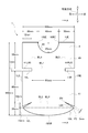
- FIG. 1 is a plan view showing an example of the overall shape of the scrotum sheet 1.
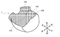
- FIG. 2 is a perspective view showing a state when the scrotum sheet 1 is about to be folded backward.
- the scrotum sheet 1 has a vertically long shape elongated in one direction as a whole.
- descriptions such as left and right, front and rear, and top and bottom mean each direction for the scrotum sheet 1.
- the scrotal sheet 1 is a sheet for wrapping the scrotum in a three-dimensional shape at the time of use. Specifically, as shown in FIG. 2, when mounted on the scrotum, it is folded backward along the five fold lines BL1 to BL5 to form a three-dimensional shape.
- the scrotum sheet 1 is divided into a plurality of regions by fold lines BL1 to BL5 indicated by alternate long and short dash lines in the figure.
- the fold BL1 also functions as a cutting line for partitioning the surface protection film 4 into a plurality of portions 40 and 41.
- the fold lines BL1 to BL3 in the present embodiment are three straight lines that divide the scrotum sheet 1 into four in the vertical direction, and the fold lines BL4 and BL5 are two lines that divide the scrotum sheet 1 into three in the left-right direction. It is a straight line.
- the vertical distance from the upper end 1UE of the scrotum sheet 1 to the fold line BL1 is preferably 35 to 60 mm, and the vertical distance from the fold line BL1 to the fold line BL2 is preferably 50 to 65 mm.
- the vertical distance from the fold line BL2 to the fold line BL3 is preferably 5 to 20 mm.
- the left-right distance from the left end 1LE to the crease BL4 is preferably 10 to 20 mm
- the left-right distance from the fold BL4 to the fold BL5 is preferably 50 to 65 mm
- the distance in the left-right direction to the right end 1RE is preferably 10 to 20 mm.
- the scrotum sheet 1 has a shape that is vertically long in a vertical direction in a plan view.
- “longitudinal” means that in the scrotum sheet 1, the long side (140 mm in this embodiment) extending in the vertical direction is longer than the short side (100 mm in this embodiment) extending in the left-right direction. Means.
- the scrotal sheet 1 is provided with a plurality of cuts for forming a three-dimensional shape and wrapping the scrotum when used.
- At least one of the cuts is a cut formed at one end for passing the penis.
- a notch indicated by reference numeral 10 is formed in the upper end 1UE. This notch 10 is formed in the center part of the left-right direction in the upper end part 1UE of the scrotum sheet 1.
- the notch 10 has a semicircular shape in plan view.
- the size of the notch 10 is preferably a radius of 15 to 25 mm, and an opening length of 15 to 25 mm.
- the distance in the left-right direction from the left side 10LE of the notch 10 to the left side 1LE of the scrotal sheet 1 is preferably 25 to 35 mm.
- the distance in the left-right direction from the right end 10RE of the cut 10 to the right side 1RE of the scrotum sheet 1 is preferably 25 to 35 mm.
- the cuts 11L and 12L are formed in the left side 1LE as shown in FIG. 1, and are cut for raising the left side 1LE by bending as shown in FIG.
- the cuts 11R and 12R are formed in the right side 1RE, and are cuts for folding the right side 1RE backward and raising it.
- the pair of cuts 11L and 11R are formed along the fold line BL1, and have a rectangular shape elongated in the left-right direction in plan view.
- the pair of cuts 12L and 12R are formed along the fold line BL2, and have a V shape in plan view.
- the notches 11L and 11R and the notches 12L and 12R that are configured as a pair and do not need to be specifically distinguished from each other are provided with reference numerals and dimensions of the respective parts only for the notches 11R and 12R in order to simplify the drawing.
- the symbols and dimensions of each part may be omitted as appropriate.
- the sizes of the cuts 11L and 11R in this embodiment are preferably 10 to 25 mm for the long side and 1 to 3 mm for the short side.
- the vertical separation distance between the upper end 1UE and the upper side 11LUS of the cut 11L is preferably 40 to 55 mm.
- the separation distance between the upper end 1UE and the upper side 11RUS of the cut 11R is preferably 45 to 55 mm.
- the sizes of the cuts 12L and 12R are preferably such that the distance from the intersection P1 of the two straight lines forming the V shape to the lower end P2 of the opening is 10 mm, as shown in FIG. Moreover, it is preferable that the opening length of the notches 12L and 12R is 5 mm.
- seat 1 is formed in area
- the lower end 1DE has a rounded shape in plan view.
- the vertical distance from the lower end R2 of the opening to the lowest end 1MDE of the lower end 1DE is preferably 15 to 40 mm.
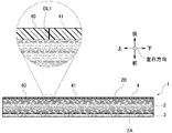
- FIG. 3 is an enlarged view of a part of the cross section taken along the line AA in FIG.
- the scrotum sheet 1 includes a plaster / water retention material layer 2, a surface material layer 3, and a surface protection film 4.
- the scrotal sheet 1 in this embodiment includes a plaster / water retention material layer 2, a surface protection film 4, and a surface material layer 3 interposed between the plaster / water retention material layer 2 and the surface protection film 4. It has a three-layer structure.
- the plaster / water-retaining material layer 2 contains at least water and a cooling sensation material using heat of vaporization when the water evaporates.
- the plaster / water-retaining material layer 2 preferably contains I-menthol having an excellent antibacterial effect as a cooling sensation material from the viewpoint of keeping the scrotum sheet 1 clean.
- the content of I-menthol is preferably 0.1% by weight to 1.0% by weight with respect to the total weight of water from the viewpoint of realizing the scrotal sheet 1 that prevents dermatitis.
- the weight of the plaster / water retention material layer 2 is preferably 0.2 to 0.4 g per cm 2 from the viewpoint of realizing the scrotal sheet 1 having an excellent antibacterial effect.
- the plaster / water-retaining material layer 2 is selected from any one of peppermint, basil, tea tree, eucalyptus, lemon, and blue gum from the viewpoint of giving the patient a mental effect such as a feeling of relaxation and sleepiness. It is preferable to contain an aroma component.
- the plaster / water-retaining material layer 2 preferably contains a preservative composed of parabens from the viewpoint of reducing the risk of mold growth.
- the surface material layer 3 is made of a nonwoven fabric in which fibers are irregularly entangled, and is formed on one surface 2A of the plaster / water retention material layer 2.
- the surface protective film 4 is made of a biocompatible resin such as polyethylene, polypropylene, and polyimide.
- the surface protective film 4 is formed on the other surface 2 ⁇ / b> B of the plaster / water retaining material layer 2.
- This surface 2B functions as an attachment surface 2B to the scrotum.
- the surface protective film 4 is configured to be peelable from the other surface 2B of the plaster / water retaining material layer 2 by the cutting line BL1.
- FIGS. 4 to 6 are diagrams for explaining an example of a mounting procedure using the scrotum sheet according to the present embodiment.
- FIG. 4 is a perspective view showing a state when the surface protective film 4 affixed to the plaster / water-retaining material layer 2 is half peeled.
- the surface 2B is shaded for easy understanding of the drawing.
- FIG. 5 is a front view of the scrotal sheet attached to the crotch.
- FIG. 6 is a side view of the scrotal sheet mounted between the groins.
- the scrotum sheet 1 is shaded for easy understanding of the drawings.
- the part 40 is peeled upward (in the direction indicated by arrow A1 in the figure).
- the portion 40 is peeled off from the surface 2B, and only the upper half of the surface 2B (the upper portion of BL1 shown in FIG. 5) is exposed to the outside first.
- a notch 10 is formed in the upper half of the surface 2B.
- the upper half (not shown) of the surface 2B is disposed opposite to the base portion of the penis so as to surround the base portion of the penis with the cut 10.
- the upper half of the surface 2B is affixed onto the skin at the base of the opposing penis.
- the notch 10 has a semicircular shape in a plan view, the penis can be exposed to the outside when the scrotum sheet 1 is attached to the crotch, and at the center in the left-right direction. Can be placed.
- the remaining part 41 is peeled downward (in the direction indicated by arrow A2 in the figure).
- the remaining portion 41 is peeled off and the lower half of the surface 2B (the lower portion than BL1 shown in FIG. 5) is also exposed to the outside, and the entire surface 2B is exposed to the outside.
- the lower half of the surface 2B is placed opposite to the scrotal region below the base of the penis.
- the scrotal sheet 1 is pulled in the left-right direction and the downward direction, and the cut positions 11L, 11R, 12L, and 12R are spread in a V shape as shown in FIG. Adjust as appropriate.
- the scrotum sheet 1 is folded in a mountain state along the folds BL1 to BL5, and the lower half of the surface 2B is attached to the skin of the opposing scrotum region. Thereby, as shown in FIG. 6, the scrotum sheet
- seat 1 is mounted
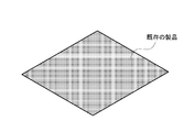
- FIG. 7 shows a perspective view of an existing product formed in a rectangular shape in plan view.
- FIG. 8 is a perspective view showing a state in which the existing product is mounted on the scrotum of the subject. As shown in FIG. 7, the existing product has square corners in plan view. Therefore, as shown in FIG.
- a gap is formed between the existing product and the scrotum, or bent portions formed at the four corners come into contact with underwear (not shown) when attached to the scrotum. Therefore, existing products are easy to peel off from the scrotum and have poor adhesion to the scrotum, and are not suitable for mounting on the scrotum.
- the incisions 12L and 12R have a V-shape in plan view (see FIG. 1), and therefore the expansion and contraction of the scrotum sheet 1 in the downward direction and the backward direction is promoted.
- the effect of being easy and difficult to peel off can be realized, and flexible and smooth alignment with respect to the intended application site can be realized.
- the lower end 1DE of the region R4 is rounded in plan view (see FIG. 1), it functions as a cushioning material that absorbs an impact at the time of collision with the flange, and the lower end 1DE collides with the flange. Even so, it is possible to prevent the buttocks from being scratched or injured, or to obtain an effect that the buttocks do not hurt even if the lower end 1DE contacts.
- the cut 10 has a semicircular shape in plan view.
- the shape is not necessarily limited to this shape as long as it is easy to wrap the scrotum. It can be formed in various shapes such as a shape. Further, the number of the cuts 10 is not limited to one and may be two or more.
- the notches 11L and 11R have a rectangular shape elongated in the left-right direction in plan view.
- the shape is not necessarily limited to this shape as long as it is easy to wrap the scrotum, and various shapes can be formed.
- the number of the cuts 11L and 11R is not limited to two, and may be one or three or more.
- the notches 12L and 12R have a V shape in plan view has been described, but the shape is not necessarily limited to this shape as long as it is easy to wrap the scrotum, and various shapes can be formed. Further, the number of the cuts 12L and 12R is not limited to two, and may be one or three or more.
- FIG. 9 is a photograph showing changes in scrotal surface temperature when a scrotal cooling sheet is attached. As shown in FIG. 9, in this experiment, the temperature was measured at four points of the scrotum, and the cooling effect of the scrotum was examined by comparing the measured temperature with the thigh temperature. Specifically, as shown in FIG.
- the temperature was measured at a point a at the upper right of the testis, a point b at the lower right of the testis, a point c at the upper left of the testis, a point d at the lower left of the testis, and the thigh.
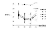
- FIG. 10 is a graph showing the relationship between scrotal temperature and thigh temperature.
- the horizontal axis of FIG. 10 shows the elapsed time [h] after the scrotum cooling sheet is applied, and the vertical axis shows the temperature [° C.].
- “ ⁇ ” indicates the average temperature at the point a (see FIG. 9) at the upper right of the testis
- “ ⁇ ” indicates the average temperature at the point b (see FIG. 9) at the lower right of the testis.
- “ ⁇ ” in FIG. 10 indicates the average temperature at the point c (see FIG.
- FIG. 10 indicates the scrotum temperature at 0 [h] at the start of application of the scrotal cooling sheet and 4 [h] after application, and the shadow at 1 [h] and 2 [h] after application. It shows that a significant difference between the sac temperature was observed at the significance level p ⁇ 0.05.
- the “significant level p” means “a level at which the difference may be statistically meaningful”, and means that the smaller the value of p, the less likely it is to happen.
- the scrotum temperature at each point a to d is a temperature of 33 [° C.] to 34 [° C.] at 0 [h] at the start of applying the scrotum cooling sheet and 4 [h] after application. It was found to be distributed within the range.
- the scrotum temperature at each of the points a to d is 32 [° C.] to 33 [° C.] in 1 [h] after applying the scrotal cooling sheet and 2 [h] after applying the scrotum cooling sheet. It was found to be distributed within the temperature range.
- the scrotal temperature at each point a to d is 1 [h] and 2 [h] after application compared to 0 [h] at the start of application and 4 [h] after application. It was found to have a significantly lower cooling effect.
- the thigh temperature is found to be distributed around 36 [° C.] at 0 [h] at the start of applying the scrotal cooling sheet and 1 [h], 2 [h], and 4 [h] after application. It was.
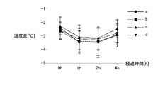
- FIG. 11 is a graph showing the temperature difference between the scrotum temperature and the thigh temperature.
- the horizontal axis in FIG. 11 indicates the elapsed time [h] after the scrotum cooling sheet is applied, and the vertical axis indicates the temperature difference between the scrotum temperature and the thigh temperature.
- “ ⁇ ” in FIG. 11 indicates a temperature difference [° C.] between the average temperature at the point a (see FIG. 9) at the upper right of the testis and the average temperature at the thigh of the subject (see FIG. 9).
- “ ⁇ ” in FIG. 11 indicates a temperature difference [° C.] between the average temperature at the point b (see FIG.
- “ ⁇ ” in FIG. 11 indicates the temperature difference [° C.] between the average temperature at the point c (see FIG. 9) at the upper left of the testis of the subject and the average temperature at the thigh of the subject (see FIG. 9). “ ⁇ ” in FIG. 11 indicates a temperature difference [° C.] between the average temperature at the point d (see FIG. 9) at the lower left of the testis of the subject and the average temperature at the thigh of the subject (see FIG. 9).
- the temperature difference from the thigh temperature at each point a to d is from ⁇ 3 [° C.] to ⁇ 2 at 0 [h] at the start of application of the scrotal cooling sheet and 4 [h] after application. It was found to be distributed within the range of [° C.].
- the temperature difference from the thigh temperature at each of the points a to d is about ⁇ 3.5 [° C. between 1 [h] after applying the scrotal cooling sheet and 2 [h] after applying the scrotum cooling sheet. ] To -3 [° C.].
- the temperature difference from the thigh temperature at each point a to d is 0 [h] at the start of application and 4 [h] after application at 1 [h] and 2 [h] after application. It was found to have a significant cooling effect and a high cooling effect.
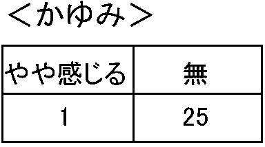
- Table 2 shows the results of evaluating the presence or absence of itching at the time of applying the scrotal cooling sheet according to the scoring criteria of “feel a little” or “none”, with 26 subjects applying the scrotal cooling sheet. Show.
Landscapes
- Health & Medical Sciences (AREA)
- Life Sciences & Earth Sciences (AREA)
- General Health & Medical Sciences (AREA)
- Animal Behavior & Ethology (AREA)
- Public Health (AREA)
- Veterinary Medicine (AREA)
- Engineering & Computer Science (AREA)
- Physics & Mathematics (AREA)
- Thermal Sciences (AREA)
- Biomedical Technology (AREA)
- Heart & Thoracic Surgery (AREA)
- Vascular Medicine (AREA)
- Chemical & Material Sciences (AREA)
- Medicinal Chemistry (AREA)
- Pharmacology & Pharmacy (AREA)
- Epidemiology (AREA)
- Agronomy & Crop Science (AREA)
- Pest Control & Pesticides (AREA)
- Plant Pathology (AREA)
- Dentistry (AREA)
- Wood Science & Technology (AREA)
- Zoology (AREA)
- Environmental Sciences (AREA)
- Thermotherapy And Cooling Therapy Devices (AREA)
- Medicinal Preparation (AREA)
- Absorbent Articles And Supports Therefor (AREA)
- Materials For Medical Uses (AREA)
Abstract
Description
図1は、陰嚢シート1の全体形状の一例を示す平面視図である。図2は、陰嚢シート1を後方に折り曲げようとした時の状態を示す斜視図である。
陰嚢シート1は、使用時に立体形状にして陰嚢を包むための複数の切り込みを備える。
切り込みの少なくとも1つは、陰茎を通すために一端部に形成された切り込みである。本実施形態では、図1に示すように、上端部1UEに符号10で示す切り込みが形成されている。この切り込み10は、陰嚢シート1の上端部1UEにおいて左右方向の中央部に形成されている。
切り込み11L、12Lは図1に示すように左側部1LEに形成され、図2に示すように該左側部1LEを折り曲げて立ち上げるための切り込みである。同様に、切り込み11R、12Rは右側部1REに形成され、該右側部1REを後方に折り曲げて立ち上げるための切り込みである。一対の切り込み11L、11Rは、折り目BL1に沿って形成され、平面視において左右方向に細長い長方形状を有している。一対の切り込み12L、12Rは、折り目BL2に沿って形成され、平面視においてV字形状を有している。
続いて、陰嚢シート1の層構造について説明する。
膏体・保水材層2は、水分と、当該水分が蒸発する際の気化熱を利用した冷感素材とを少なくとも含有している。
表面材層3は、繊維を不規則にからめた不織布からなり、前記膏体・保水材層2の一方の面2Aに形成される。
表面保護フィルム4は、ポリエチレン、ポリプロピレン、ポリイミドなどの生体適合性樹脂からなる。表面保護フィルム4は、前記膏体・保水材層2の他方の面2Bに形成される。この面2Bは、陰嚢への貼付面2Bとして機能する。表面保護フィルム4は、図3の一点鎖線で囲まれた部分を拡大した図に示すように、切断線BL1によって複数の部位40、41に区画されている。この切断線BL1によって、表面保護フィルム4は前記膏体・保水材層2の他方の面2Bから剥離可能に構成されている。
図4~図6は、本実施形態に係る陰嚢シートを用いた装着手順の一例を説明するための図である。
ここでは、19歳から22歳までの健康な若年男性26名を被験者とした。
ここでは、陰嚢温度と大腿温度との比較により、陰嚢冷却シートの冷却効果を検討した。
図10は、陰嚢温度と大腿温度との関係を示したグラフである。図10の横軸は陰嚢冷却シートの貼付後の経過時間[h]を示し、縦軸は温度[℃]を示す。図10中の「●」は、被験者の精巣右上の点a(図9参照)における平均温度を示し、「■」は、被験者の精巣右下の点b(図9参照)における平均温度を示す。また、図10中の「▲」は、被験者の精巣左上の点c(図9参照)における平均温度を示し、「▼」は、被験者の精巣左下の点d(図9参照)における平均温度を示す。図10中の「◆」は、被験者の大腿(図9参照)における平均温度を示す。
図11は、陰嚢温度と大腿温度との温度差を示したグラフである。図11の横軸は陰嚢冷却シートの貼付後の経過時間[h]を示し、縦軸は陰嚢温度と大腿温度との温度差を示す。図11中の「●」は、被験者の精巣右上の点a(図9参照)における平均温度と、被験者の大腿(図9参照)における平均温度との温度差[℃]を示す。図11中の「■」は、被験者の精巣右下の点b(図9参照)における平均温度と、被験者の大腿(図9参照)における平均温度との温度差[℃]を示す。図11中の「▲」は、被験者の精巣左上の点c(図9参照)における平均温度と、被験者の大腿(図9参照)における平均温度との温度差[℃]を示す。図11中の「▼」は、被験者の精巣左下の点d(図9参照)における平均温度と、被験者の大腿(図9参照)における平均温度との温度差[℃]を示す。
本発明者らは、本実験において、陰嚢冷却シートの貼付後の着け心地や、かゆみの有無についても検討した。
以下の表1は、被験者26名が陰嚢冷却シートの貼付を行い、「とてもよい」、「よい」、「ふつう」、「悪い」、「とても悪い」の採点基準で着け心地を評価した結果を示す。

以下の表2は、被験者26名が陰嚢冷却シートの貼付を行い、「やや感じる」、「無」、の採点基準で、陰嚢冷却シートの貼付時における、かゆみの有無を評価した結果を示す。
2 膏体・保水材層
2A、2B 面
3 表面材層
4 表面保護フィルム
10、11L、11R、12L、12R 切り込み
Claims (4)
- 水分と、当該水分が蒸発する際の気化熱を利用した冷感素材とを少なくとも含有する膏体・保水材層と、
前記膏体・保水材層の一方の面に形成された表面材層と、
使用時に立体形状にして陰嚢を包むための切り込みとを備えたことを特徴とする陰嚢シート。 - 請求項1において、
前記切り込みの少なくとも1つが、陰茎を通すために一端部に形成された切り込みであることを特徴とする陰嚢シート。 - 請求項1又は請求項2において、
前記切り込みの少なくとも1つが、
両側部に形成され、該両側部をそれぞれ折り曲げて立ち上げるための切り込みであることを特徴とする陰嚢シート。 - 請求項1乃至請求項3のいずれか一項において、
前記膏体・保水材層の他方の面に形成され、複数の部位に区画された表面保護フィルムを更に備えたことを特徴とする陰嚢シート。
Priority Applications (5)
| Application Number | Priority Date | Filing Date | Title |
|---|---|---|---|
| US16/073,895 US10799391B2 (en) | 2016-02-05 | 2017-01-06 | Scrotal sheet |
| KR1020187021949A KR102114794B1 (ko) | 2016-02-05 | 2017-01-06 | 음낭 시트 |
| JP2017565439A JP6368441B2 (ja) | 2016-02-05 | 2017-01-06 | 陰嚢シート |
| CN201780001005.8A CN107405212B (zh) | 2016-02-05 | 2017-01-06 | 阴囊贴片 |
| EP17747141.4A EP3412258A4 (en) | 2016-02-05 | 2017-01-06 | SKROTUMFOLIE |
Applications Claiming Priority (2)
| Application Number | Priority Date | Filing Date | Title |
|---|---|---|---|
| JP2016-021250 | 2016-02-05 | ||
| JP2016021250 | 2016-02-05 |
Publications (1)
| Publication Number | Publication Date |
|---|---|
| WO2017134977A1 true WO2017134977A1 (ja) | 2017-08-10 |
Family
ID=59499713
Family Applications (1)
| Application Number | Title | Priority Date | Filing Date |
|---|---|---|---|
| PCT/JP2017/000196 Ceased WO2017134977A1 (ja) | 2016-02-05 | 2017-01-06 | 陰嚢シート |
Country Status (6)
| Country | Link |
|---|---|
| US (1) | US10799391B2 (ja) |
| EP (1) | EP3412258A4 (ja) |
| JP (1) | JP6368441B2 (ja) |
| KR (1) | KR102114794B1 (ja) |
| CN (1) | CN107405212B (ja) |
| WO (1) | WO2017134977A1 (ja) |
Cited By (1)
| Publication number | Priority date | Publication date | Assignee | Title |
|---|---|---|---|---|
| WO2019208393A1 (ja) * | 2018-04-27 | 2019-10-31 | ミツボシプロダクトプラニング株式会社 | 陰嚢シート |
Families Citing this family (2)
| Publication number | Priority date | Publication date | Assignee | Title |
|---|---|---|---|---|
| USD1038434S1 (en) | 2023-03-30 | 2024-08-06 | AMPK Holdings, LLC | Scrotal insulator |
| USD1047156S1 (en) | 2023-11-21 | 2024-10-15 | AMPK Holdings, LLC | Testicle cooling device |
Citations (7)
| Publication number | Priority date | Publication date | Assignee | Title |
|---|---|---|---|---|
| JPS57148944A (en) * | 1981-03-02 | 1982-09-14 | Ripuro Medo Shisutemusu Inc | Male contraceptive treating method and apparatus |
| JP3031041U (ja) * | 1996-05-09 | 1996-11-12 | ダイヤ製薬株式会社 | 保冷・保湿用貼付材 |
| JP2001299807A (ja) * | 2000-04-18 | 2001-10-30 | Ooshin Medical:Kk | 外用貼付剤 |
| JP3083311U (ja) * | 2001-03-31 | 2002-01-25 | ヨン−ソク ユン | 男根及び睾丸用湿布器具 |
| JP3166764U (ja) * | 2010-12-24 | 2011-03-24 | 川田工業株式会社 | クーラーパッド |
| US20130331917A1 (en) * | 2008-10-02 | 2013-12-12 | Urology Inventions, Llc | Methods and apparati for the close application of therapeutic and other devices to the pelvic area |
| US20130338742A1 (en) * | 2012-06-14 | 2013-12-19 | Mr. Mila Michael Gallen | Apparatus and method for thermal therapy treatment to male genitalia |
Family Cites Families (14)
| Publication number | Priority date | Publication date | Assignee | Title |
|---|---|---|---|---|
| US4253464A (en) | 1979-09-24 | 1981-03-03 | Repro Med Systems, Inc. | Method and device for contributing to the obviating of male infertility |
| JPS6215328U (ja) | 1985-07-10 | 1987-01-29 | ||
| WO1994000087A1 (en) * | 1992-06-22 | 1994-01-06 | Ergomed, Inc. | Versatile therapeutic cold pack |
| US6723115B1 (en) * | 2000-09-27 | 2004-04-20 | Respironics Novametrix, Inc. | Disposable body part warmer and method of use |
| EP1420732A4 (en) * | 2000-12-11 | 2009-05-13 | Young-Whan Yu | PORTABLE COOLANT |
| KR20020045930A (ko) * | 2000-12-11 | 2002-06-20 | 유영환 | 정자 보호를 위해 냉각/냉동물질을 이용한 냉각착용물 |
| KR100445882B1 (ko) * | 2001-03-03 | 2004-08-25 | 유영환 | 정자 보호를 위한 냉각 착용물 |
| US7065983B2 (en) * | 2003-06-06 | 2006-06-27 | Albert Long Trinh | Adhesive ice bag device |
| DE102007036496A1 (de) * | 2007-08-01 | 2009-02-05 | Duetto Licence Ag | Vorrichtung zur Kühlung |
| CN202526407U (zh) * | 2012-04-10 | 2012-11-14 | 重庆医科大学附属儿童医院 | 阴茎阴囊手术包扎敷贴 |
| CN203400241U (zh) * | 2013-05-27 | 2014-01-22 | 施敬东 | 睾丸冷敷贴 |
| US20150157493A1 (en) * | 2013-12-09 | 2015-06-11 | Arif H. Agha, MD | Genital Shield for Reducing the Transmission of Sexually Transmitted Diseases |
| TWM495095U (zh) | 2014-09-01 | 2015-02-11 | zhong-yi Zhang | 男性陰囊涼爽墊 |
| US20160331048A1 (en) * | 2015-05-13 | 2016-11-17 | Jean Dawn Runcie | Bruise prevention pads |
-
2017
- 2017-01-06 WO PCT/JP2017/000196 patent/WO2017134977A1/ja not_active Ceased
- 2017-01-06 KR KR1020187021949A patent/KR102114794B1/ko active Active
- 2017-01-06 EP EP17747141.4A patent/EP3412258A4/en not_active Ceased
- 2017-01-06 JP JP2017565439A patent/JP6368441B2/ja active Active
- 2017-01-06 CN CN201780001005.8A patent/CN107405212B/zh active Active
- 2017-01-06 US US16/073,895 patent/US10799391B2/en active Active
Patent Citations (7)
| Publication number | Priority date | Publication date | Assignee | Title |
|---|---|---|---|---|
| JPS57148944A (en) * | 1981-03-02 | 1982-09-14 | Ripuro Medo Shisutemusu Inc | Male contraceptive treating method and apparatus |
| JP3031041U (ja) * | 1996-05-09 | 1996-11-12 | ダイヤ製薬株式会社 | 保冷・保湿用貼付材 |
| JP2001299807A (ja) * | 2000-04-18 | 2001-10-30 | Ooshin Medical:Kk | 外用貼付剤 |
| JP3083311U (ja) * | 2001-03-31 | 2002-01-25 | ヨン−ソク ユン | 男根及び睾丸用湿布器具 |
| US20130331917A1 (en) * | 2008-10-02 | 2013-12-12 | Urology Inventions, Llc | Methods and apparati for the close application of therapeutic and other devices to the pelvic area |
| JP3166764U (ja) * | 2010-12-24 | 2011-03-24 | 川田工業株式会社 | クーラーパッド |
| US20130338742A1 (en) * | 2012-06-14 | 2013-12-19 | Mr. Mila Michael Gallen | Apparatus and method for thermal therapy treatment to male genitalia |
Non-Patent Citations (1)
| Title |
|---|
| See also references of EP3412258A4 * |
Cited By (2)
| Publication number | Priority date | Publication date | Assignee | Title |
|---|---|---|---|---|
| WO2019208393A1 (ja) * | 2018-04-27 | 2019-10-31 | ミツボシプロダクトプラニング株式会社 | 陰嚢シート |
| TWI808969B (zh) * | 2018-04-27 | 2023-07-21 | 日商三星產品策劃股份有限公司 | 陰囊貼片 |
Also Published As
| Publication number | Publication date |
|---|---|
| JP6368441B2 (ja) | 2018-08-01 |
| KR20180099829A (ko) | 2018-09-05 |
| JPWO2017134977A1 (ja) | 2018-08-16 |
| CN107405212B (zh) | 2018-12-04 |
| CN107405212A (zh) | 2017-11-28 |
| US20190038457A1 (en) | 2019-02-07 |
| EP3412258A1 (en) | 2018-12-12 |
| KR102114794B1 (ko) | 2020-05-25 |
| EP3412258A4 (en) | 2019-09-18 |
| US10799391B2 (en) | 2020-10-13 |
Similar Documents
| Publication | Publication Date | Title |
|---|---|---|
| JP6368441B2 (ja) | 陰嚢シート | |
| US9138026B2 (en) | Facial cushion | |
| US10231881B2 (en) | Therapeutic compression garment and method of applying the garment | |
| JP2019183346A5 (ja) | ||
| JP2013138702A (ja) | 使い捨ておむつ | |
| JP5904970B2 (ja) | 使い捨ておむつ | |
| WO2019208393A1 (ja) | 陰嚢シート | |
| KR102821431B1 (ko) | 팬티형 흡수성 물품 | |
| JP2020054500A5 (ja) | ||
| JP4478612B2 (ja) | テーピングテープ | |
| JP2021029684A5 (ja) | ||
| US20140031731A1 (en) | Relating to a therapeutic foot support | |
| US20120053618A1 (en) | Open Airways Accupressure Sinus Pillow | |
| JP3162912U7 (ja) | ||
| CN309077023S (zh) | 发热颈托(KPF-Neck11) | |
| CN309208530S (zh) | 床垫(8h超大口径护脊弹簧) | |
| CN309877804S (zh) | 护目镜(kg02) | |
| KR200472635Y1 (ko) | 관절용 패치 | |
| US1237285A (en) | Bunion-protector. | |
| JP3202939U (ja) | 腰痛解消マットレス | |
| JP2013172789A (ja) | 吸収物品。 | |
| JP2024154801A5 (ja) | ||
| JP2023003359A5 (ja) | ||
| JP6219660B2 (ja) | 着用物品 | |
| TWI295181B (ja) |
Legal Events
| Date | Code | Title | Description |
|---|---|---|---|
| 121 | Ep: the epo has been informed by wipo that ep was designated in this application |
Ref document number: 17747141 Country of ref document: EP Kind code of ref document: A1 |
|
| ENP | Entry into the national phase |
Ref document number: 2017565439 Country of ref document: JP Kind code of ref document: A |
|
| ENP | Entry into the national phase |
Ref document number: 20187021949 Country of ref document: KR Kind code of ref document: A |
|
| NENP | Non-entry into the national phase |
Ref country code: DE |
|
| WWE | Wipo information: entry into national phase |
Ref document number: 2017747141 Country of ref document: EP |
|
| ENP | Entry into the national phase |
Ref document number: 2017747141 Country of ref document: EP Effective date: 20180905 |