WO2017135131A1 - カテーテル - Google Patents
カテーテル Download PDFInfo
- Publication number
- WO2017135131A1 WO2017135131A1 PCT/JP2017/002641 JP2017002641W WO2017135131A1 WO 2017135131 A1 WO2017135131 A1 WO 2017135131A1 JP 2017002641 W JP2017002641 W JP 2017002641W WO 2017135131 A1 WO2017135131 A1 WO 2017135131A1
- Authority
- WO
- WIPO (PCT)
- Prior art keywords
- coil
- tube
- catheter
- gear
- catheter according
- Prior art date
- Legal status (The legal status is an assumption and is not a legal conclusion. Google has not performed a legal analysis and makes no representation as to the accuracy of the status listed.)
- Ceased
Links
Images


Classifications
-
- A—HUMAN NECESSITIES
- A61—MEDICAL OR VETERINARY SCIENCE; HYGIENE
- A61M—DEVICES FOR INTRODUCING MEDIA INTO, OR ONTO, THE BODY; DEVICES FOR TRANSDUCING BODY MEDIA OR FOR TAKING MEDIA FROM THE BODY; DEVICES FOR PRODUCING OR ENDING SLEEP OR STUPOR
- A61M25/00—Catheters; Hollow probes
- A61M25/0043—Catheters; Hollow probes characterised by structural features
- A61M25/005—Catheters; Hollow probes characterised by structural features with embedded materials for reinforcement, e.g. wires, coils, braids
- A61M25/0053—Catheters; Hollow probes characterised by structural features with embedded materials for reinforcement, e.g. wires, coils, braids having a variable stiffness along the longitudinal axis, e.g. by varying the pitch of the coil or braid
-
- A—HUMAN NECESSITIES
- A61—MEDICAL OR VETERINARY SCIENCE; HYGIENE
- A61M—DEVICES FOR INTRODUCING MEDIA INTO, OR ONTO, THE BODY; DEVICES FOR TRANSDUCING BODY MEDIA OR FOR TAKING MEDIA FROM THE BODY; DEVICES FOR PRODUCING OR ENDING SLEEP OR STUPOR
- A61M25/00—Catheters; Hollow probes
-
- A—HUMAN NECESSITIES
- A61—MEDICAL OR VETERINARY SCIENCE; HYGIENE
- A61M—DEVICES FOR INTRODUCING MEDIA INTO, OR ONTO, THE BODY; DEVICES FOR TRANSDUCING BODY MEDIA OR FOR TAKING MEDIA FROM THE BODY; DEVICES FOR PRODUCING OR ENDING SLEEP OR STUPOR
- A61M25/00—Catheters; Hollow probes
- A61M25/0009—Making of catheters or other medical or surgical tubes
- A61M25/0012—Making of catheters or other medical or surgical tubes with embedded structures, e.g. coils, braids, meshes, strands or radiopaque coils
-
- A—HUMAN NECESSITIES
- A61—MEDICAL OR VETERINARY SCIENCE; HYGIENE
- A61M—DEVICES FOR INTRODUCING MEDIA INTO, OR ONTO, THE BODY; DEVICES FOR TRANSDUCING BODY MEDIA OR FOR TAKING MEDIA FROM THE BODY; DEVICES FOR PRODUCING OR ENDING SLEEP OR STUPOR
- A61M25/00—Catheters; Hollow probes
- A61M25/01—Introducing, guiding, advancing, emplacing or holding catheters
- A61M25/0105—Steering means as part of the catheter or advancing means; Markers for positioning
- A61M25/0133—Tip steering devices
- A61M25/0136—Handles therefor
-
- A—HUMAN NECESSITIES
- A61—MEDICAL OR VETERINARY SCIENCE; HYGIENE
- A61M—DEVICES FOR INTRODUCING MEDIA INTO, OR ONTO, THE BODY; DEVICES FOR TRANSDUCING BODY MEDIA OR FOR TAKING MEDIA FROM THE BODY; DEVICES FOR PRODUCING OR ENDING SLEEP OR STUPOR
- A61M25/00—Catheters; Hollow probes
- A61M25/0043—Catheters; Hollow probes characterised by structural features
- A61M25/0045—Catheters; Hollow probes characterised by structural features multi-layered, e.g. coated
Definitions
- the present invention relates to a catheter that is inserted into a living body lumen, and more particularly to a catheter for guiding a medical instrument such as a treatment catheter to a target site.
- the catheter described in Patent Document 1 includes a catheter main body having a soft tube, a coil embedded in the tube and functioning as a core material, and a hub provided at a proximal end portion of the catheter main body.
- the hub When pushing the catheter inside the blood vessel, for example, the hub may be rotated in order to change the direction of the distal end, and the rotational force may be transmitted to the catheter body to rotate the distal end.
- the coil functions as a core material, it is easy to transmit the rotational force to the tip (torque transmission).
- the tube is made of a flexible soft material, depending on its length, the rotational force that rotates the hub is not sufficiently transmitted to the distal end of the catheter body, resulting in operability. Decreases.
- An object of the present invention is to provide a catheter excellent in operability.
- an inner pipe Provided on the outer peripheral side of the inner tube, and comprising a coil tube formed of a coil formed by winding a wire,
- the coil tube has at least one first coil, and at least one second coil that is arranged concentrically with the first coil, and in which the winding direction of the wire is different from the first coil,
- the catheter wherein the inner tube and the coiled tube are rotatable relative to each other around their central axes.
- the catheter is inserted into the living body from the distal end side, 5.
- the rotation operation unit has a cylindrical operation tube, The catheter according to (5), wherein a central axis of the operation tube coincides with a central axis of the coiled tube.
- the rotation operation unit includes a first gear fixed to the coil tube, and a second gear meshing with the first gear, The catheter according to (5) above, wherein the coil tube is rotated by rotating the second gear.
- the entire catheter can be rotated by rotating the coil tube. That is, the coiled tube is responsible for transmitting the rotational force.
- the coil tube is composed of the first coil and the second coil whose winding directions are different from each other, when the coil tube is rotated in the same direction as the winding direction of the first coil, the diameter of the first coil increases. While the force is applied to shorten the length, the second coil is tightened to reduce the diameter, and the force is applied to increase the length. On the other hand, when the first coil is rotated in the direction opposite to the winding direction, the first coil is reduced in diameter and a force is applied to increase the length, whereas the second coil is increased in diameter and lengthened. Force is applied to shorten the length.
- the rotational force can be efficiently transmitted to the tip of the coil tube.
- the third coil when there is a third coil having a winding direction different from that of the second coil, the third coil is expanded in diameter, and a force is applied so that the length is shortened in the length direction.
- the presence of the inner tube improves the passability of a guide wire, a treatment device, etc., and facilitates the injection of a liquid such as a contrast medium.
- the catheter of the present invention is excellent in operability such as torque transmission and direction selectivity.
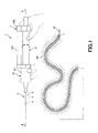
- FIG. 1 is a side view showing a catheter (first embodiment) of the present invention.
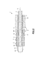
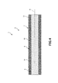
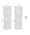
- FIG. 2 is a longitudinal sectional view of a catheter main body provided in the catheter shown in FIG. 3 is a cross-sectional view taken along line AA in FIG. 4 is a longitudinal sectional view of the coiled tube shown in FIG. 5 is a partially omitted view of the side view of the coiled tube shown in FIG. 1, in which (a) shows a state rotated in the arrow B direction, and (b) rotates in the arrow C direction.
- FIG. FIG. 6 is a side view showing a catheter (second embodiment) of the present invention.
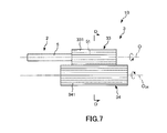
- FIG. 7 is a side view showing a rotation operation unit provided in the catheter (third embodiment) of the present invention.
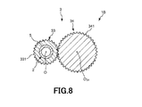
- FIG. 8 is a cross-sectional view taken along the line DD in FIG.
- FIG. 9 is a side view showing a rotation operation unit provided in the catheter (fourth embodiment) of the present invention.
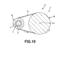
- 10 is a cross-sectional view taken along line EE in FIG.
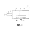
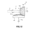
- FIG. 11 is a side view showing a rotation operation unit provided in the catheter (fifth embodiment) of the present invention.
- FIG. 12 is a side view showing the first gear and the second gear shown in FIG.
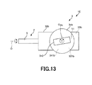
- FIG. 13 is a top view showing a rotation operation unit provided in the catheter (sixth embodiment) of the present invention.
- FIG. 14 is a side view showing the first gear and the second gear shown in FIG.
- FIG. 1 is a side view showing a catheter (first embodiment) of the present invention.
- FIG. 2 is a longitudinal sectional view of a catheter main body provided in the catheter shown in FIG. 3 is a cross-sectional view taken along line AA in FIG. 4 is a longitudinal sectional view of the coiled tube shown in FIG. 5 is a partially omitted view of the side view of the coiled tube shown in FIG. 1, in which (a) shows a state rotated in the arrow B direction, and (b) rotates in the arrow C direction.
- the upper side of FIGS. 1 to 5 (the same applies to FIGS. 6 to 14) is “upper” or “upper”, the lower side is “lower” or “lower”, and the left side is “
- the “left” or “tip” is called the “right” or “base”. That is, in the catheter, the catheter main body side is referred to as the “tip”, and the opposite side (the rotation operation unit side) is referred to as the “base end”.
- a catheter 1 shown in FIG. 1 includes a catheter body 2 inserted into a blood vessel 100 and a rotation operation unit 3 provided at a proximal end portion of the catheter body 2.
- the catheter body 2 has flexibility and has a triple tube structure including an inner tube 4, a coil tube 5, and an outer tube 6. Further, the inner tube 4, the coil tube 5 and the outer tube 6 are arranged concentrically in this order from the inside around the central axis O of the catheter body 2.
- the inner tube 4 is composed of a flexible tube.
- the proximal end 41 of the inner tube 4 is fixed to the rotation operation unit 3.
- the coil tube 5 is composed of a coil.
- the coil tube 5 is shorter than the inner tube 4, and the base end portion 51 thereof is located on the front end side of the base end portion 41 of the inner tube 4. For this reason, the base end portion 41 of the inner tube 4 is exposed from the base end opening of the coil tube 5.
- a cylindrical tip 52 is fixed to the tip of the coil tube 5.
- the distal tip 52 has a cylindrical shape and is located closer to the distal side than the inner tube 4 and the outer tube 6.
- the tip 52 has a taper portion 521 whose outer diameter gradually decreases toward the tip side. Thereby, for example, it can be made easy to enter the constriction part.
- the outer tube 6 is composed of a flexible tube.
- the outer tube 6 is shorter than the coil tube 5, and the base end portion 61 is located on the front end side of the base end portion 51 of the coil tube 5. For this reason, the base end portion 51 of the coil tube 5 is exposed from the base end opening of the outer tube 6.
- a gap is formed between the inner tube 4 and the coil tube 5. Thereby, it is possible to prevent the inner tube 4 from inhibiting the rotation of the coil tube 5.
- the outer tube 6 is provided on the outer peripheral portion, a distal-side tubular portion 62 on the distal end side with respect to the central portion S, and a proximal-side tubular portion on the proximal side with respect to the central portion S. 63.
- the distal tubular portion 62 functions as an undercoat layer for the hydrophilic coat.
- the distal tubular portion 62 is made of a material having a relatively high affinity with a hydrophilic coat, such as polyurethane. Thereby, the affinity of the outer tube 6 and the hydrophilic coat can be increased. Therefore, it is possible to prevent the hydrophilic coat from peeling from the outer tube 6.
- the proximal end side tubular portion 63 is made of a resin material having relatively high rigidity such as nylon or polyurethane. Thereby, the outer tube
- a flexible resin material can be used as a constituent material of the inner tube 4, the outer tube 6, and the tip 52.
- a flexible resin material can be used.
- high density polyethylene polyolefin such as polypropylene, polyamide such as nylon 66, polyurethane, and polyethylene.
- polyesters such as terephthalate, polybutylene terephthalate, polycyclohexane terephthalate, polytetrafluoroethylene, ethylene-tetrafluoroethylene copolymer and the like.
- the inner tube 4, the outer tube 6, and the tip chip 52 may be a multilayer tube made of a coil or a braided member made of the resin material, metal material, or the like.
- these materials are materials having a relatively small frictional resistance (low friction material), in particular, by configuring the inner tube 4 with such a material, for example, an operation for inserting a guide wire into the inner tube 4 or drawing out the guide wire. Operations and the like can be performed easily and reliably.
- Such a constituent material may contain particles composed of a radiopaque material (radiopaque material).
- a radiopaque material include tungsten, bismuth oxide, and barium sulfate.
- a film made of silicon resin or the like may be formed on the inner surface of the inner tube 4. Thereby, the frictional force is further reduced on the inner surface of the inner tube 4.
- the inner peripheral surface of the coil tube 5 or the outer peripheral surface of the inner tube 4 is coated with a silicone resin, a hydrophilic coat, a lubricating oil, or the like. May be.
- the hydrophilic coat is not particularly limited, and a hydrophilic polymer material that exhibits lubricity when contacted with a liquid such as blood or physiological saline can be used. As a result, the frictional resistance of the catheter body 2 is reduced and the slidability is further improved, so that the insertion operation into the meandering blood vessel 100 becomes easier.
- a hydrophilic high molecular material for example, a cellulose polymer substance (for example, hydroxypropyl cellulose), a polyethylene oxide type polymer substance (for example, polyethylene glycol), a maleic anhydride type polymer substance (for example, methyl) Vinyl ether-maleic anhydride copolymer), acrylamide polymer (for example, dimethylacrylamide-glycidyl methacrylate copolymer), water-soluble nylon and the like can be used alone or in combination.
- a cellulose polymer substance for example, hydroxypropyl cellulose
- a polyethylene oxide type polymer substance for example, polyethylene glycol
- a maleic anhydride type polymer substance for example, methyl
- Vinyl ether-maleic anhydride copolymer for example, acrylamide polymer (for example, dimethylacrylamide-glycidyl methacrylate copolymer), water-soluble nylon and the like
- acrylamide polymer for example, dimethylacrylamide-glycidyl me
- the hydrophilic coating may be omitted, and the outer peripheral portion of the outer tube 6 may be subjected to a hydrophilic treatment that increases hydrophilicity.
- this hydrophilic treatment include physical activation treatment such as plasma treatment, glow discharge, corona discharge, and ultraviolet irradiation.
- the constituent material of the coil tube 5 may be a resin material or a metal material, but is preferably a metal material from the viewpoint of increasing rigidity.
- metal material examples include stainless steel (for example, SUS304, SUS303, SUS316, SUS316L, SUS316J1, SUS316J1L, SUS405, SUS430, SUS434, SUS444, SUS429, SUS430F, SUS302, etc.), piano wire, cobalt alloy, Ni— Ti alloy etc. are mentioned.
- the coil tube 5 is provided non-fixed to the inner tube 4 and the outer tube 6 over the extension in the longitudinal direction. As a result, the coil tube 5 can rotate relative to the inner tube 4 and the outer tube 6.
- the rotation operation unit 3 includes an operation tube 31 and a support unit 32 that rotatably supports the operation tube 31.
- the operation cylinder 31 is composed of a cylindrical member.
- the operation tube 31 is positioned on the proximal end side extension of the central axis O of the catheter body 2. Further, a portion of the inner tube 4 exposed from the proximal ends of the coil tube 5 and the outer tube 6 is inserted into the lumen 311 of the operation tube 31.
- a bearing 312 is provided in the lumen 311 of the operation cylinder 31 and on the distal end side.
- the base end portion 51 of the coil tube 5 is fixed to the operation cylinder 31 via the bearing 312. Accordingly, when the operation cylinder 31 is rotated, the coil tube 5 rotates around the central axis O.
- the central axis of the operation tube 31 coincides with the central axis O of the catheter body 2 (the central axis of the coiled tube 5).
- the rotational force obtained by rotating the operation cylinder 31 is efficiently transmitted to the coil tube 5.
- the support portion 32 has a distal end side support portion 321 on the distal end side, a proximal end side support portion 322 on the proximal end side, and a connecting portion 323.
- the distal end side support portion 321 has a substantially cylindrical shape, and a portion of the inner tube 4 and the coil tube 5 exposed from the proximal end portion of the outer tube 6 is inserted into the inner cavity portion 324. Further, the distal end side support portion 321 has a recess 325 opened to the proximal end side. The tip 313 of the operation cylinder 31 is rotatably inserted into the recess 325.
- the distal end portion of the distal end side support portion 321 is a tapered portion 326 whose outer diameter gradually decreases toward the distal end side.
- the tapered portion 326 can be fitted to the catheter hub of the guiding catheter, and the procedure can be performed stably.
- a proximal end portion 61 of the outer tube 6 is fixed to the distal end of the tapered portion 326. Note that the tapered portion 326 may be omitted, and the proximal end portion 61 of the outer tube 6 may be directly fixed to the distal end side support portion 321.
- the proximal end support portion 322 is fixed to the distal end side support portion 321 by a connecting portion 323. Further, the proximal end side support portion 322 is fixed by inserting the inner tube 4 into the lumen portion 327. Further, the base end side support portion 322 has a concave portion 328 that is open to the tip end side. A base end 314 of the operation cylinder 31 is rotatably inserted into the recess 328.
- the base end side support portion 322 has a protruding portion (hub) 329 protruding in a cylindrical shape toward the base end side.
- a protruding portion such as a syringe
- the lumen portion 327 has a tapered portion 330 whose inner diameter increases toward the proximal end at the proximal end portion thereof, so that the other medical instrument can be fitted therein, and the connection state thereof Can be maintained.
- such a rotation operation unit 3 can be used by rotating the operation cylinder 31 with the right hand while holding and fixing the distal end side support unit 321 with the left hand, for example. it can. Thereby, the coiled tube 5 is rotated by the rotating operation.
- the operation tube 31 may be operated with the left hand and the guide wire may be operated with the right hand.
- the coil tube 5 has a triple tube structure including a coil 7 (first coil), a coil 8 (second coil), and a coil 9 (third coil).
- the coil 7, the coil 8, and the coil 9 are arranged from the outside in this order.
- the outer peripheral part and the inner peripheral part are contacting the coil 7 and the coil 8, and the coil 8 and the coil 9, respectively.
- the coil 7, the coil 8, and the coil 9 may be configured such that portions that overlap each other in the radial direction are fixed, the middle in the longitudinal direction is provided non-fixed, and the ends are It may be a fixed configuration.
- the fixing method include quenching, fusing, brazing, adhesion, and a method of collectively covering with a resin layer.
- the coil 7 and the coil 8 have different winding directions.
- the coil 7 has one wire 71 wound in a counterclockwise direction (in the direction of arrow B in FIG. 5A) from the base end side to the tip end side.
- the coil 8 has one wire 81 wound in a clockwise direction (in the direction of arrow C in FIG. 5B) from the base end side to the tip end side.
- the coil 8 and the coil 9 have different winding directions.
- the coil 9 When viewed from the base end side, the coil 9 has one wire 91 wound in a counterclockwise direction (in the direction of arrow B in FIG. 5A) from the base end side to the tip end side.
- the coil 7 and the coil 9 have the same winding direction.
- the coil 7 When the coil 7 is rotated in the same direction as the winding direction of the coil 7, that is, in the direction of arrow B in FIG. 5A, the coil 7 expands in diameter and a force is applied so that the length is shortened in the length direction.
- the coil 8 having a different winding direction from the coil 7 is tightened to reduce the diameter, and a force is applied so that the length is increased in the length direction.
- the coil 9 having a different winding direction from the coil 8 is expanded in diameter in the same manner as the coil 7, and a force is applied so that the length is shortened in the length direction.
- the coil 7 when the coil 7 is rotated in the direction opposite to the winding direction of the coil 7, that is, in the direction of arrow C in FIG. 5B, the coil 7 is tightened to reduce its diameter and the length in the length direction is reduced. While a force is applied so as to be longer, the coil 8 having a different winding direction from the coil 7 is expanded in diameter, and the force is applied so that the length is shortened in the length direction.
- the coil 9 having a winding direction different from that of the coil 8 is tightened in the same manner as the coil 7 to reduce the diameter, and a force is applied so that the length is increased in the length direction.
- each wire 71, 81, 91 is wound so that the wires adjacent to each other in the length direction are as close as possible, there is a degree of freedom in the direction extending in the length direction, but there is no play in the compression direction. Therefore, there is no escape space for the rotational stress at hand, and the rotational stress is transmitted to the tip.
- the coil tube 5 has a portion that efficiently transmits the rotational force. Therefore, for example, as shown in FIG. 1, when the direction of the distal end of the catheter 1 is changed, the rotational force is reliably transmitted to the distal end of the coiled tube 5 regardless of which direction the rotational operation is performed.
- the direction of the distal end portion of the catheter 1 together with the outer tube 6 can be changed. As a result, the catheter 1 is excellent in operability such as torque transmission and direction selectivity.
- the fixing force of the coil 7, the coil 8, and the coil 9 is stronger than the force applied in the length direction, the rotational force is effectively transmitted to the tip.
- the coil tube 5 is provided in a non-fixed manner with respect to the inner tube 4 and the outer tube 6 over the entire length thereof, and thus can be rotated independently. Therefore, it is possible to prevent the rotation of the coil tube 5 as described above from being inhibited by the inner tube 4 and the outer tube 6. Accordingly, excellent operability such as excellent torque transmission and direction selectivity of the catheter 1 can be realized.
- the rigidity of the coil tube 5 is higher than the rigidity of the inner tube 4 and the outer tube 6.
- FIG. 6 is a side view showing a catheter (second embodiment) of the present invention.
- the catheter 1A shown in FIG. 6 there is nothing equivalent to the outer tube 6 of the first embodiment. For this reason, the flexibility of the entire catheter body 2 can be increased. Furthermore, the step between the outer tube and the coil tube 5 can be eliminated and the diameter can be reduced. Further, the hydrophilic treatment described in the first embodiment is performed on the outer peripheral portion of the coil tube 5.
- FIG. 7 is a side view showing a rotation operation unit provided in the catheter (third embodiment) of the present invention.
- 8 is a cross-sectional view taken along the line DD in FIG.
- the rotation operation unit 3 in the catheter 1B, includes a first gear 33 and a second gear 34 that meshes with the first gear 33.
- the housing or frame (supporting portion) that houses the first gear 33 and the second gear 34 is not shown.
- the first gear 33 is fixed to the proximal end portion 51 of the coil tube 5.
- the first gear 33 has a cylindrical shape and is arranged concentrically with the central axis of the coiled tube 5. As the first gear 33 rotates, the coil tube 5 rotates. Further, the outer periphery of the first gear 33 extends along the longitudinal direction, and teeth 331 are formed along the circumferential direction.
- the second gear 34 is disposed on the side of the first gear 33. Further, the second gear 34 has a cylindrical shape, and the outer peripheral portion thereof extends along the longitudinal direction, and teeth 341 are formed along the circumferential direction. The teeth 341 mesh with the teeth 331 of the first gear 33. Thus, when the second gear 34 is rotated, the first gear 33 rotates, and the coil tube 5 can rotate with the rotation. Thus, the 2nd gear 34 functions as an operation part which performs rotation operation.
- the second gear 34 as the operation unit is provided such that the central axis O 34 is shifted from the central axis O of the catheter body 2. Thereby, when performing rotation operation, it can prevent that the catheter main body 2 obstructs the operation.
- FIG. 9 is a side view showing a rotation operation unit provided in the catheter (fourth embodiment) of the present invention. 10 is a cross-sectional view taken along line EE in FIG.
- the rotation operation unit 3 includes a first pulley 35, a second pulley 36, and a belt 37.
- the first pulley 35 has a cylindrical shape, and the proximal end portion of the coil tube 5 is fixed to the inside of the first pulley 35.
- the first pulley 35 is provided concentrically with the catheter body 2 around the central axis O of the catheter body 2.
- the second pulley 36 has a cylindrical shape, and is disposed on the side of the first pulley 35 so as to be separated from the first pulley 35.
- Two belts 37 are wound around the first pulley 35 and the second pulley 36.
- the belt 37 is wound around the distal end portion of the first pulley 35 and the distal end portion of the second pulley 36, and the proximal end portion of the first pulley 35 and the proximal end portion of the second pulley 36.
- the rotational force is transmitted to the first pulley 35 via the two belts 37, and the first pulley 35 rotates. .
- the coil tube 5 can rotate.
- the 2nd pulley 36 functions as an operation part which performs rotation operation.
- the second pulley 36 as the operation portion can be further away from the central axis O of the catheter body 2. Therefore, when performing rotation operation, it can prevent more effectively that the catheter main body 2 inhibits the operation.
- FIG. 11 is a side view showing a rotation operation unit provided in the catheter (fifth embodiment) of the present invention.
- FIG. 12 is a side view showing the first gear and the second gear shown in FIG.
- the rotation operation unit 3 includes a support unit 30a, a first gear 33a provided in the support unit 30a, and a second gear 34a.
- the first gear 33a is housed in the support portion 30a. Further, the first gear 33 a is fixed to the proximal end portion 51 of the coil tube 5.
- the first gear 33 a is configured by a bevel gear having teeth 331 a and is disposed concentrically with the central axis of the coiled tube 5. As the first gear 33a rotates, the coil tube 5 rotates.
- the second gear 34a is disposed on the side of the first gear 33a.
- the 2nd gear 34a is comprised with the disk shaped bevel gear like the 1st gear 33a. Further, the second gear 34 a is disposed in a direction in which the central axis O 34 a intersects the central axis O of the catheter body 2.
- the second gear 34a has teeth 341a, and the teeth 341a mesh with the teeth 331a of the first gear 33a. Accordingly, when the second gear 34a is rotated, the first gear 33a rotates, and the coil tube 5 can rotate with the rotation. Thus, the 2nd gear 34a functions as an operation part which performs rotation operation.
- the second gear 34a has a part of its outer peripheral portion exposed from the support portion 30a, and can be rotated.
- the second gear 34a as the operation portion is a so-called “dial type”, and the fine adjustment of the rotation operation can be easily performed.
- the marker which shows rotation amount can be attached
- FIG. 13 is a top view showing a rotation operation unit provided in the catheter (sixth embodiment) of the present invention.
- FIG. 14 is a side view showing the first gear and the second gear shown in FIG.
- the rotation operation unit 3 includes a support unit 30b, a first gear 33b provided in the support unit 30b, and a second gear 34b.
- the first gear 33b is accommodated in the support portion 30b. Further, the first gear 33 b is fixed to the proximal end portion 51 of the coil tube 5. Further, the first gear 33 b is constituted by a crown gear having teeth 331 b and is arranged concentrically with the central axis of the coil tube 5. As the first gear 33b rotates, the coil tube 5 rotates.
- the second gear 34b is disposed on the side of the first gear 33b.
- the second gear 34b is configured by a disk-shaped bevel gear. Further, the second gear 34 b is disposed in a direction in which the central axis O 34 b intersects the central axis O of the catheter body 2.
- the second gear 34b has teeth 341b, and the teeth 341b mesh with the teeth 331b of the first gear 33b. Accordingly, when the second gear 34b is rotated, the first gear 33b is rotated, and the coil tube 5 is rotated with the rotation.
- the 2nd gear 34b functions as an operation part which performs rotation operation.
- the second gear 34b has a grip portion 342 formed to protrude in a prismatic shape on the side opposite to the teeth 341b. Thereby, it is possible to easily operate the second gear 34b by gripping the grip portion 342.
- the second gear 34b has a portion other than the teeth 341b (including the grip portion 342) exposed from the support portion 30b, and can be rotated.
- illustration of the support part 30b is abbreviate
- the second gear 34b as the operation portion is a so-called “dial type”, and fine adjustment of the rotation operation can be easily performed. .
- each part constituting the catheter can be replaced with an arbitrary structure that can exhibit the same function. can do.
- arbitrary components may be added.
- the coil tube has one each of the first coil, the second coil, and the third coil.
- the present invention is not limited to this, and a plurality of coils are provided. Also good.
- the coil tube may be one in which a coil wire having the same inner diameter and outer diameter is knitted and fixed.
- the catheter of the present invention includes an inner tube and a coil tube that is provided on the outer peripheral side of the inner tube and is configured by a coil wound with a wire, and the coil tube includes at least one first coil.
- the first and second coils are arranged concentrically with at least one second coil in which the winding direction of the wire is different from the first coil, and the inner tube and the coil tube have their centers It is characterized by being rotatable relative to each other around an axis.
- the coil tube since the coil tube is rotatably provided to the inner tube, the entire catheter can be rotated by rotating the coil tube. That is, the coiled tube is responsible for transmitting the rotational force.
- the coil tube is composed of the first coil and the second coil whose winding directions are different from each other, when the coil tube is rotated in the same direction as the winding direction of the first coil, the diameter of the first coil increases. While the force is applied to shorten the length, the second coil is tightened to reduce the diameter, and the force is applied to increase the length. On the other hand, when the first coil is rotated in the direction opposite to the winding direction, the first coil is reduced in diameter and a force is applied to increase the length, whereas the second coil is increased in diameter and lengthened. Force is applied to shorten the length. As described above, according to the present invention, the rotational force can be efficiently transmitted to the tip of the coil tube because the rotational force is easily transmitted regardless of which direction the coil tube is rotated.
Landscapes
- Health & Medical Sciences (AREA)
- Life Sciences & Earth Sciences (AREA)
- Biophysics (AREA)
- Pulmonology (AREA)
- Engineering & Computer Science (AREA)
- Anesthesiology (AREA)
- Biomedical Technology (AREA)
- Heart & Thoracic Surgery (AREA)
- Hematology (AREA)
- Animal Behavior & Ethology (AREA)
- General Health & Medical Sciences (AREA)
- Public Health (AREA)
- Veterinary Medicine (AREA)
- Media Introduction/Drainage Providing Device (AREA)
Abstract
Description
このような治療法としては、カテーテルの長尺性を利用して、マイクロカテーテル、サポートカテーテル、造影カテーテルまたはガイディングカテーテルを用いて、直接、患部(病変部)に薬剤を投与する方法、動脈瘤や出血箇所あるいは栄養血管に詰め物をして閉じる方法、加圧によって拡張するバルーンを先端に取り付けた処置用カテーテルをガイディングカテーテルなどに通して、血管内の狭窄部まで到達させた後に、加圧によってバルーンを拡張して押し広げて開く方法等がある。
(1)内管と、
前記内管の外周側に設けられ、線材が巻回されてなるコイルで構成されたコイル管とを備え、
前記コイル管は、少なくとも1つの第1コイルと、前記第1コイルと同心的に配置され、前記線材の巻回方向が前記第1コイルとは異なる少なくとも1つの第2コイルとを有し、
前記内管と前記コイル管とは、それらの中心軸回りに互いに相対的に回転可能であることを特徴とするカテーテル。
前記コイル管の基端部に固定され、回転操作されることによりその回転力を前記コイル管に伝達する回転操作部をさらに有している上記(1)ないし(4)のいずれかに記載のカテーテル。
前記操作筒は、その中心軸が前記コイル管の中心軸と一致している上記(5)に記載のカテーテル。
前記第2ギアを回転操作することにより前記コイル管が回転する上記(5)に記載のカテーテル。
前記外管と前記コイル管とは、それらの中心軸回りに相対的に回転可能である上記(1)ないし(7)のいずれかに記載のカテーテル。
以上より、本発明のカテーテルは、トルク伝達性と方向選択性といった操作性に優れる。
図1は、本発明のカテーテル(第1実施形態)を示す側面図である。図2は、図1に示すカテーテルが備えるカテーテル本体の縦断面図である。図3は、図1中のA-A線断面図である。図4は、図1に示すコイル管の縦断面図である。図5は、図1に示すコイル管の側面図の一部省略図であって、(a)が矢印B方向に回転させた状態を示す図であり、(b)が矢印C方向に回転させた状態を示す図である。
また、コイル管5と内管4の摩擦を軽減させるために、コイル管5の内周面または内管4の外周面には、シリコン樹脂、親水性コート、潤滑油等のコーティングが施されていてもよい。
図3に示すように、回転操作部3は、操作筒31と、操作筒31を回転可能に支持する支持部32とを有している。
図4に示すように、コイル管5は、コイル7(第1コイル)と、コイル8(第2コイル)と、コイル9(第3コイル)とを有する三重管構造をなしている。コイル7、コイル8およびコイル9は、この順で外側から配置されている。また、コイル7およびコイル8、コイル8およびコイル9は、それぞれ外周部と内周部が接触している。
また、前述したように、コイル管5は、その全長に亘って内管4および外管6に対して非固定的に設けられているため、独立して回転することができる。よって、上述したようなコイル管5の回転が内管4および外管6によって阻害されるのを防止することができる。よって、カテーテル1の優れたトルク伝達性と方向選択性等、優れた操作性を実現することができる。
図6は、本発明のカテーテル(第2実施形態)を示す側面図である。
本実施形態は、カテーテル本体の構成が異なること以外は、前記第1実施形態と同様である。以下の実施形態でも同様である。
図7は、本発明のカテーテル(第3実施形態)が備える回転操作部を示す側面図である。図8は、図7中のD-D線断面図である。
また、第1ギア33の外周部には、その長手方向に沿って延在し、周方向に沿って歯331が形成されている。
図9は、本発明のカテーテル(第4実施形態)が備える回転操作部を示す側面図である。図10は、図9中のE-E線断面図である。
これら第1プーリー35および第2プーリー36には、2本のベルト37が掛け回されている。ベルト37は、第1プーリー35の先端部および第2プーリー36の先端部と、第1プーリー35の基端部および第2プーリー36の基端部とにそれぞれ掛け回されている。
図11は、本発明のカテーテル(第5実施形態)が備える回転操作部を示す側面図である。図12は、図11に示す第1ギアおよび第2ギアを示す側面図である。
第2ギア34aは、第1ギア33aの側方に配置されている。また、第2ギア34aは、第1ギア33aと同様に円盤状の傘歯車で構成されている。また、第2ギア34aは、その中心軸O34aがカテーテル本体2の中心軸Oと交差する向きで配置されている。
なお、第2ギア34aは、その外周部の一部が支持部30aから露出しており、回転操作を行うことができる。
図13は、本発明のカテーテル(第6実施形態)が備える回転操作部を示す上面図である。図14は、図13に示す第1ギアおよび第2ギアを示す側面図である。
この第2ギア34bは、歯341bを有し、この歯341bが第1ギア33bの歯331bと噛合している。これにより、第2ギア34bを回転操作すると、第1ギア33bが回転し、その回転とともにコイル管5が回転する。このように、第2ギア34bは、回転操作を行う操作部として機能する。
2 カテーテル本体
3 回転操作部
30、30a、30b 支持部
31 操作筒
311 内腔部
312 ベアリング
313 先端部
314 基端部
32 支持部
321 先端側支持部
322 基端側支持部
323 連結部
324 内腔部
325 凹部
326 テーパ部
327 内腔部
328 凹部
329 突出部
330 テーパ部
33、33a、33b 第1ギア
331、331a、331b 歯
34、34a、34b 第2ギア
341、341a、341b 歯
342 把持部
35 第1プーリー
36 第2プーリー
37 ベルト
4 内管
41 基端部
5 コイル管
51 基端部
52 先端チップ
521 テーパ部
6 外管
61 基端部
62 先端側管状部
63 基端側管状部
7 コイル
71 線材
8 コイル
81 線材
9 コイル
91 線材
100 血管
O 中心軸
O34、O34a、O34b、O36 中心軸
S 中央部
Claims (9)
- 内管と、
前記内管の外周側に設けられ、線材が巻回されてなるコイルで構成されたコイル管とを備え、
前記コイル管は、少なくとも1つの第1コイルと、前記第1コイルと同心的に配置され、前記線材の巻回方向が前記第1コイルとは異なる少なくとも1つの第2コイルとを有し、
前記内管と前記コイル管とは、それらの中心軸回りに互いに相対的に回転可能であることを特徴とするカテーテル。 - 当該カテーテルに外力を付与しない自然状態では、前記内管と前記コイル管との間には、間隙が形成されている請求項1に記載のカテーテル。
- 前記第1コイルの内側に前記第2コイルが配置されている請求項1または2に記載のカテーテル。
- 前記第2コイルの内側に設けられ、前記第2コイルと異なる方向に線材が巻回されてなる第3コイルを有する請求項1ないし3のいずれか1項に記載のカテーテル。
- 当該カテーテルは、先端側から生体内に挿入されるものであり、
前記コイル管の基端部に固定され、回転操作されることによりその回転力を前記コイル管に伝達する回転操作部をさらに有している請求項1ないし4のいずれか1項に記載のカテーテル。 - 前記回転操作部は、筒状の操作筒を有し、
前記操作筒は、その中心軸が前記コイル管の中心軸と一致している請求項5に記載のカテーテル。 - 前記回転操作部は、前記コイル管に固定された第1ギアと、前記第1ギアと噛合する第2ギアとを有し、
前記第2ギアを回転操作することにより前記コイル管が回転する請求項5に記載のカテーテル。 - 前記コイル管の外周側に設けられた外管をさらに有し、
前記外管と前記コイル管とは、それらの中心軸回りに相対的に回転可能である請求項1ないし7のいずれか1項に記載のカテーテル。 - 前記外管は、その外周部に親水性を高める親水性処理が施されている請求項8に記載のカテーテル。
Priority Applications (4)
| Application Number | Priority Date | Filing Date | Title |
|---|---|---|---|
| EP17747290.9A EP3412329B1 (en) | 2016-02-05 | 2017-01-26 | Catheter |
| JP2017565505A JP6879945B2 (ja) | 2016-02-05 | 2017-01-26 | カテーテル |
| US16/052,978 US10994094B2 (en) | 2016-02-05 | 2018-08-02 | Catheter |
| US17/222,091 US11890428B2 (en) | 2016-02-05 | 2021-04-05 | Catheter |
Applications Claiming Priority (2)
| Application Number | Priority Date | Filing Date | Title |
|---|---|---|---|
| JP2016-021365 | 2016-02-05 | ||
| JP2016021365 | 2016-02-05 |
Related Child Applications (1)
| Application Number | Title | Priority Date | Filing Date |
|---|---|---|---|
| US16/052,978 Continuation US10994094B2 (en) | 2016-02-05 | 2018-08-02 | Catheter |
Publications (1)
| Publication Number | Publication Date |
|---|---|
| WO2017135131A1 true WO2017135131A1 (ja) | 2017-08-10 |
Family
ID=59500714
Family Applications (1)
| Application Number | Title | Priority Date | Filing Date |
|---|---|---|---|
| PCT/JP2017/002641 Ceased WO2017135131A1 (ja) | 2016-02-05 | 2017-01-26 | カテーテル |
Country Status (4)
| Country | Link |
|---|---|
| US (2) | US10994094B2 (ja) |
| EP (1) | EP3412329B1 (ja) |
| JP (1) | JP6879945B2 (ja) |
| WO (1) | WO2017135131A1 (ja) |
Cited By (2)
| Publication number | Priority date | Publication date | Assignee | Title |
|---|---|---|---|---|
| WO2019039011A1 (ja) * | 2017-08-24 | 2019-02-28 | 株式会社カネカ | バスケットカテーテルおよびその製造方法ならびに医療用処置具 |
| JP2019063134A (ja) * | 2017-09-29 | 2019-04-25 | フクダ電子株式会社 | カテーテル |
Families Citing this family (5)
| Publication number | Priority date | Publication date | Assignee | Title |
|---|---|---|---|---|
| DE102018208537A1 (de) | 2018-05-30 | 2019-12-05 | Kardion Gmbh | Vorrichtung zum Anbinden eines Herzunterstützungssystems an eine Einführeinrichtung und Verfahren zum Herstellen einer Vorrichtung zum Anbinden eines Herzunterstützungssystems an eine Einführeinrichtung |
| DE102018208564A1 (de) | 2018-05-30 | 2019-12-05 | Kardion Gmbh | Steuerbare Einführungshülse |
| DE102018208555A1 (de) | 2018-05-30 | 2019-12-05 | Kardion Gmbh | Vorrichtung zum Verankern eines Herzunterstützungssystems in einem Blutgefäß, Verfahren zum Betreiben und Herstellverfahren zum Herstellen einer Vorrichtung und Herzunterstützungssystem |
| DE102018211297A1 (de) | 2018-07-09 | 2020-01-09 | Kardion Gmbh | Herzunterstützungssystem und Verfahren zur Überwachung der Integrität einer Haltestruktur eines Herzunterstützungssystems |
| AU2021383931A1 (en) | 2020-11-20 | 2023-07-06 | Kardion Gmbh | Mechanical circulatory support system with guidewire aid |
Citations (3)
| Publication number | Priority date | Publication date | Assignee | Title |
|---|---|---|---|---|
| JP2002272852A (ja) * | 2002-01-08 | 2002-09-24 | Terumo Corp | 脳動脈用カテーテルおよびカテーテル器具 |
| JP2005058304A (ja) * | 2003-08-08 | 2005-03-10 | Terumo Corp | イントロデューサーシース |
| JP2011177231A (ja) * | 2010-02-26 | 2011-09-15 | Patentstra Co Ltd | 医療用コイル構造体と、その製造方法、並びに医療用コイル構造体を形成して成る医療用内視鏡と、医療用処置具と、超音波診断医療用カテーテルと、光干渉診断医療用カテーテル |
Family Cites Families (6)
| Publication number | Priority date | Publication date | Assignee | Title |
|---|---|---|---|---|
| CA2016178A1 (en) * | 1989-05-08 | 1990-11-08 | Rodney G. Wolff | Ptca catheter |
| JP3659664B2 (ja) * | 1994-05-31 | 2005-06-15 | テルモ株式会社 | 医療用チューブ |
| JP3587567B2 (ja) * | 1994-09-08 | 2004-11-10 | テルモ株式会社 | カテーテルチューブ |
| US6419644B1 (en) * | 1998-09-08 | 2002-07-16 | Scimed Life Systems, Inc. | System and method for intraluminal imaging |
| WO2003043685A2 (en) * | 2001-11-19 | 2003-05-30 | Cardiovascular Systems, Inc | High torque, low profile intravascular guidewire system |
| US20070083132A1 (en) * | 2005-10-11 | 2007-04-12 | Sharrow James S | Medical device coil |
-
2017
- 2017-01-26 EP EP17747290.9A patent/EP3412329B1/en active Active
- 2017-01-26 JP JP2017565505A patent/JP6879945B2/ja active Active
- 2017-01-26 WO PCT/JP2017/002641 patent/WO2017135131A1/ja not_active Ceased
-
2018
- 2018-08-02 US US16/052,978 patent/US10994094B2/en active Active
-
2021
- 2021-04-05 US US17/222,091 patent/US11890428B2/en active Active
Patent Citations (3)
| Publication number | Priority date | Publication date | Assignee | Title |
|---|---|---|---|---|
| JP2002272852A (ja) * | 2002-01-08 | 2002-09-24 | Terumo Corp | 脳動脈用カテーテルおよびカテーテル器具 |
| JP2005058304A (ja) * | 2003-08-08 | 2005-03-10 | Terumo Corp | イントロデューサーシース |
| JP2011177231A (ja) * | 2010-02-26 | 2011-09-15 | Patentstra Co Ltd | 医療用コイル構造体と、その製造方法、並びに医療用コイル構造体を形成して成る医療用内視鏡と、医療用処置具と、超音波診断医療用カテーテルと、光干渉診断医療用カテーテル |
Non-Patent Citations (1)
| Title |
|---|
| See also references of EP3412329A4 * |
Cited By (5)
| Publication number | Priority date | Publication date | Assignee | Title |
|---|---|---|---|---|
| WO2019039011A1 (ja) * | 2017-08-24 | 2019-02-28 | 株式会社カネカ | バスケットカテーテルおよびその製造方法ならびに医療用処置具 |
| CN110545741A (zh) * | 2017-08-24 | 2019-12-06 | 株式会社钟化 | 网篮导管及其制造方法以及医疗用处置器具 |
| JPWO2019039011A1 (ja) * | 2017-08-24 | 2020-08-06 | 株式会社カネカ | バスケットカテーテルおよびその製造方法ならびに医療用処置具 |
| US11596425B2 (en) | 2017-08-24 | 2023-03-07 | Kaneka Corporation | Basket catheter, method for producing the same and medical treatment instrument |
| JP2019063134A (ja) * | 2017-09-29 | 2019-04-25 | フクダ電子株式会社 | カテーテル |
Also Published As
| Publication number | Publication date |
|---|---|
| EP3412329B1 (en) | 2021-09-08 |
| US20180344975A1 (en) | 2018-12-06 |
| EP3412329A4 (en) | 2020-04-29 |
| JPWO2017135131A1 (ja) | 2018-11-29 |
| EP3412329A1 (en) | 2018-12-12 |
| JP6879945B2 (ja) | 2021-06-02 |
| US20210220606A1 (en) | 2021-07-22 |
| US10994094B2 (en) | 2021-05-04 |
| US11890428B2 (en) | 2024-02-06 |
Similar Documents
| Publication | Publication Date | Title |
|---|---|---|
| JP6879945B2 (ja) | カテーテル | |
| AU2017217879A1 (en) | Intravascular treatment site access | |
| JP2001095923A (ja) | カテーテル | |
| JP6765415B2 (ja) | ガイドワイヤ | |
| WO2020225935A1 (ja) | ガイドワイヤ | |
| WO2024090107A1 (ja) | カテーテル | |
| WO2020031409A1 (ja) | ガイドワイヤ | |
| JP2005305185A (ja) | 医療用チューブ | |
| CN219614692U (zh) | 一种导丝 | |
| JP2006271901A (ja) | コイル状造影マーカーとその製造方法、及びカテーテル | |
| JP2016154632A (ja) | 医療用長尺体 | |
| JP7545339B2 (ja) | 多層コイル | |
| JP2020039377A (ja) | ガイドワイヤ | |
| WO2022034648A1 (ja) | ガイドワイヤ | |
| JP2021090683A (ja) | ガイドワイヤ、ガイドワイヤの製造方法 | |
| JP2024100601A (ja) | カテーテル | |
| WO2024171960A1 (ja) | ガイドワイヤ | |
| JP2024027763A (ja) | 医療用長尺体 | |
| WO2022185624A1 (ja) | バルーンカテーテル | |
| JP6313183B2 (ja) | ガイドワイヤ | |
| JP2025026113A (ja) | ガイドワイヤ | |
| JP2021036923A (ja) | ガイドワイヤ | |
| WO2024171959A1 (ja) | ガイドワイヤ | |
| WO2023095694A1 (ja) | カテーテル | |
| WO2025062987A1 (ja) | ガイドワイヤ |
Legal Events
| Date | Code | Title | Description |
|---|---|---|---|
| 121 | Ep: the epo has been informed by wipo that ep was designated in this application |
Ref document number: 17747290 Country of ref document: EP Kind code of ref document: A1 |
|
| WWE | Wipo information: entry into national phase |
Ref document number: 2017565505 Country of ref document: JP |
|
| NENP | Non-entry into the national phase |
Ref country code: DE |
|
| WWE | Wipo information: entry into national phase |
Ref document number: 2017747290 Country of ref document: EP |
|
| ENP | Entry into the national phase |
Ref document number: 2017747290 Country of ref document: EP Effective date: 20180905 |