WO2017135305A1 - ユーザ装置および基地局 - Google Patents
ユーザ装置および基地局 Download PDFInfo
- Publication number
- WO2017135305A1 WO2017135305A1 PCT/JP2017/003605 JP2017003605W WO2017135305A1 WO 2017135305 A1 WO2017135305 A1 WO 2017135305A1 JP 2017003605 W JP2017003605 W JP 2017003605W WO 2017135305 A1 WO2017135305 A1 WO 2017135305A1
- Authority
- WO
- WIPO (PCT)
- Prior art keywords
- base station
- unit
- transmission
- power
- received power
- Prior art date
- Legal status (The legal status is an assumption and is not a legal conclusion. Google has not performed a legal analysis and makes no representation as to the accuracy of the status listed.)
- Ceased
Links
Images


Classifications
-
- H—ELECTRICITY
- H04—ELECTRIC COMMUNICATION TECHNIQUE
- H04B—TRANSMISSION
- H04B7/00—Radio transmission systems, i.e. using radiation field
- H04B7/02—Diversity systems; Multi-antenna system, i.e. transmission or reception using multiple antennas
- H04B7/04—Diversity systems; Multi-antenna system, i.e. transmission or reception using multiple antennas using two or more spaced independent antennas
- H04B7/06—Diversity systems; Multi-antenna system, i.e. transmission or reception using multiple antennas using two or more spaced independent antennas at the transmitting station
- H04B7/0613—Diversity systems; Multi-antenna system, i.e. transmission or reception using multiple antennas using two or more spaced independent antennas at the transmitting station using simultaneous transmission
- H04B7/0615—Diversity systems; Multi-antenna system, i.e. transmission or reception using multiple antennas using two or more spaced independent antennas at the transmitting station using simultaneous transmission of weighted versions of same signal
- H04B7/0619—Diversity systems; Multi-antenna system, i.e. transmission or reception using multiple antennas using two or more spaced independent antennas at the transmitting station using simultaneous transmission of weighted versions of same signal using feedback from receiving side
- H04B7/0636—Feedback format
- H04B7/0645—Variable feedback
-
- H—ELECTRICITY
- H04—ELECTRIC COMMUNICATION TECHNIQUE
- H04B—TRANSMISSION
- H04B17/00—Monitoring; Testing
- H04B17/30—Monitoring; Testing of propagation channels
- H04B17/309—Measuring or estimating channel quality parameters
- H04B17/318—Received signal strength
-
- H—ELECTRICITY
- H04—ELECTRIC COMMUNICATION TECHNIQUE
- H04B—TRANSMISSION
- H04B17/00—Monitoring; Testing
- H04B17/30—Monitoring; Testing of propagation channels
- H04B17/309—Measuring or estimating channel quality parameters
- H04B17/336—Signal-to-interference ratio [SIR] or carrier-to-interference ratio [CIR]
-
- H—ELECTRICITY
- H04—ELECTRIC COMMUNICATION TECHNIQUE
- H04B—TRANSMISSION
- H04B17/00—Monitoring; Testing
- H04B17/30—Monitoring; Testing of propagation channels
- H04B17/309—Measuring or estimating channel quality parameters
- H04B17/345—Interference values
-
- H—ELECTRICITY
- H04—ELECTRIC COMMUNICATION TECHNIQUE
- H04B—TRANSMISSION
- H04B7/00—Radio transmission systems, i.e. using radiation field
- H04B7/02—Diversity systems; Multi-antenna system, i.e. transmission or reception using multiple antennas
- H04B7/022—Site diversity; Macro-diversity
- H04B7/024—Co-operative use of antennas of several sites, e.g. in co-ordinated multipoint or co-operative multiple-input multiple-output [MIMO] systems
-
- H—ELECTRICITY
- H04—ELECTRIC COMMUNICATION TECHNIQUE
- H04B—TRANSMISSION
- H04B7/00—Radio transmission systems, i.e. using radiation field
- H04B7/02—Diversity systems; Multi-antenna system, i.e. transmission or reception using multiple antennas
- H04B7/04—Diversity systems; Multi-antenna system, i.e. transmission or reception using multiple antennas using two or more spaced independent antennas
- H04B7/06—Diversity systems; Multi-antenna system, i.e. transmission or reception using multiple antennas using two or more spaced independent antennas at the transmitting station
- H04B7/0613—Diversity systems; Multi-antenna system, i.e. transmission or reception using multiple antennas using two or more spaced independent antennas at the transmitting station using simultaneous transmission
- H04B7/0615—Diversity systems; Multi-antenna system, i.e. transmission or reception using multiple antennas using two or more spaced independent antennas at the transmitting station using simultaneous transmission of weighted versions of same signal
- H04B7/0617—Diversity systems; Multi-antenna system, i.e. transmission or reception using multiple antennas using two or more spaced independent antennas at the transmitting station using simultaneous transmission of weighted versions of same signal for beam forming
-
- H—ELECTRICITY
- H04—ELECTRIC COMMUNICATION TECHNIQUE
- H04B—TRANSMISSION
- H04B7/00—Radio transmission systems, i.e. using radiation field
- H04B7/02—Diversity systems; Multi-antenna system, i.e. transmission or reception using multiple antennas
- H04B7/04—Diversity systems; Multi-antenna system, i.e. transmission or reception using multiple antennas using two or more spaced independent antennas
- H04B7/06—Diversity systems; Multi-antenna system, i.e. transmission or reception using multiple antennas using two or more spaced independent antennas at the transmitting station
- H04B7/0613—Diversity systems; Multi-antenna system, i.e. transmission or reception using multiple antennas using two or more spaced independent antennas at the transmitting station using simultaneous transmission
- H04B7/0615—Diversity systems; Multi-antenna system, i.e. transmission or reception using multiple antennas using two or more spaced independent antennas at the transmitting station using simultaneous transmission of weighted versions of same signal
- H04B7/0619—Diversity systems; Multi-antenna system, i.e. transmission or reception using multiple antennas using two or more spaced independent antennas at the transmitting station using simultaneous transmission of weighted versions of same signal using feedback from receiving side
- H04B7/0621—Feedback content
- H04B7/0626—Channel coefficients, e.g. channel state information [CSI]
-
- H—ELECTRICITY
- H04—ELECTRIC COMMUNICATION TECHNIQUE
- H04B—TRANSMISSION
- H04B7/00—Radio transmission systems, i.e. using radiation field
- H04B7/02—Diversity systems; Multi-antenna system, i.e. transmission or reception using multiple antennas
- H04B7/04—Diversity systems; Multi-antenna system, i.e. transmission or reception using multiple antennas using two or more spaced independent antennas
- H04B7/06—Diversity systems; Multi-antenna system, i.e. transmission or reception using multiple antennas using two or more spaced independent antennas at the transmitting station
- H04B7/0613—Diversity systems; Multi-antenna system, i.e. transmission or reception using multiple antennas using two or more spaced independent antennas at the transmitting station using simultaneous transmission
- H04B7/0615—Diversity systems; Multi-antenna system, i.e. transmission or reception using multiple antennas using two or more spaced independent antennas at the transmitting station using simultaneous transmission of weighted versions of same signal
- H04B7/0619—Diversity systems; Multi-antenna system, i.e. transmission or reception using multiple antennas using two or more spaced independent antennas at the transmitting station using simultaneous transmission of weighted versions of same signal using feedback from receiving side
- H04B7/0621—Feedback content
- H04B7/063—Parameters other than those covered in groups H04B7/0623 - H04B7/0634, e.g. channel matrix rank or transmit mode selection
-
- H—ELECTRICITY
- H04—ELECTRIC COMMUNICATION TECHNIQUE
- H04B—TRANSMISSION
- H04B7/00—Radio transmission systems, i.e. using radiation field
- H04B7/02—Diversity systems; Multi-antenna system, i.e. transmission or reception using multiple antennas
- H04B7/04—Diversity systems; Multi-antenna system, i.e. transmission or reception using multiple antennas using two or more spaced independent antennas
- H04B7/06—Diversity systems; Multi-antenna system, i.e. transmission or reception using multiple antennas using two or more spaced independent antennas at the transmitting station
- H04B7/0613—Diversity systems; Multi-antenna system, i.e. transmission or reception using multiple antennas using two or more spaced independent antennas at the transmitting station using simultaneous transmission
- H04B7/0615—Diversity systems; Multi-antenna system, i.e. transmission or reception using multiple antennas using two or more spaced independent antennas at the transmitting station using simultaneous transmission of weighted versions of same signal
- H04B7/0619—Diversity systems; Multi-antenna system, i.e. transmission or reception using multiple antennas using two or more spaced independent antennas at the transmitting station using simultaneous transmission of weighted versions of same signal using feedback from receiving side
- H04B7/0621—Feedback content
- H04B7/0632—Channel quality parameters, e.g. channel quality indicator [CQI]
-
- H—ELECTRICITY
- H04—ELECTRIC COMMUNICATION TECHNIQUE
- H04B—TRANSMISSION
- H04B7/00—Radio transmission systems, i.e. using radiation field
- H04B7/02—Diversity systems; Multi-antenna system, i.e. transmission or reception using multiple antennas
- H04B7/04—Diversity systems; Multi-antenna system, i.e. transmission or reception using multiple antennas using two or more spaced independent antennas
- H04B7/06—Diversity systems; Multi-antenna system, i.e. transmission or reception using multiple antennas using two or more spaced independent antennas at the transmitting station
- H04B7/0613—Diversity systems; Multi-antenna system, i.e. transmission or reception using multiple antennas using two or more spaced independent antennas at the transmitting station using simultaneous transmission
- H04B7/0615—Diversity systems; Multi-antenna system, i.e. transmission or reception using multiple antennas using two or more spaced independent antennas at the transmitting station using simultaneous transmission of weighted versions of same signal
- H04B7/0619—Diversity systems; Multi-antenna system, i.e. transmission or reception using multiple antennas using two or more spaced independent antennas at the transmitting station using simultaneous transmission of weighted versions of same signal using feedback from receiving side
- H04B7/0636—Feedback format
- H04B7/0645—Variable feedback
- H04B7/065—Variable contents, e.g. long-term or short-short
-
- H—ELECTRICITY
- H04—ELECTRIC COMMUNICATION TECHNIQUE
- H04J—MULTIPLEX COMMUNICATION
- H04J11/00—Orthogonal multiplex systems, e.g. using WALSH codes
- H04J11/0023—Interference mitigation or co-ordination
- H04J11/005—Interference mitigation or co-ordination of intercell interference
- H04J11/0053—Interference mitigation or co-ordination of intercell interference using co-ordinated multipoint transmission/reception
-
- H—ELECTRICITY
- H04—ELECTRIC COMMUNICATION TECHNIQUE
- H04L—TRANSMISSION OF DIGITAL INFORMATION, e.g. TELEGRAPHIC COMMUNICATION
- H04L5/00—Arrangements affording multiple use of the transmission path
- H04L5/003—Arrangements for allocating sub-channels of the transmission path
- H04L5/0058—Allocation criteria
- H04L5/0073—Allocation arrangements that take into account other cell interferences
-
- H—ELECTRICITY
- H04—ELECTRIC COMMUNICATION TECHNIQUE
- H04W—WIRELESS COMMUNICATION NETWORKS
- H04W16/00—Network planning, e.g. coverage or traffic planning tools; Network deployment, e.g. resource partitioning or cells structures
- H04W16/24—Cell structures
- H04W16/28—Cell structures using beam steering
-
- H—ELECTRICITY
- H04—ELECTRIC COMMUNICATION TECHNIQUE
- H04W—WIRELESS COMMUNICATION NETWORKS
- H04W24/00—Supervisory, monitoring or testing arrangements
- H04W24/10—Scheduling measurement reports ; Arrangements for measurement reports
-
- H—ELECTRICITY
- H04—ELECTRIC COMMUNICATION TECHNIQUE
- H04W—WIRELESS COMMUNICATION NETWORKS
- H04W72/00—Local resource management
- H04W72/04—Wireless resource allocation
- H04W72/044—Wireless resource allocation based on the type of the allocated resource
- H04W72/046—Wireless resource allocation based on the type of the allocated resource the resource being in the space domain, e.g. beams
-
- H—ELECTRICITY
- H04—ELECTRIC COMMUNICATION TECHNIQUE
- H04W—WIRELESS COMMUNICATION NETWORKS
- H04W72/00—Local resource management
- H04W72/20—Control channels or signalling for resource management
- H04W72/27—Control channels or signalling for resource management between access points
-
- H—ELECTRICITY
- H04—ELECTRIC COMMUNICATION TECHNIQUE
- H04W—WIRELESS COMMUNICATION NETWORKS
- H04W72/00—Local resource management
- H04W72/50—Allocation or scheduling criteria for wireless resources
- H04W72/54—Allocation or scheduling criteria for wireless resources based on quality criteria
- H04W72/541—Allocation or scheduling criteria for wireless resources based on quality criteria using the level of interference
-
- H—ELECTRICITY
- H04—ELECTRIC COMMUNICATION TECHNIQUE
- H04B—TRANSMISSION
- H04B17/00—Monitoring; Testing
- H04B17/20—Monitoring; Testing of receivers
- H04B17/24—Monitoring; Testing of receivers with feedback of measurements to the transmitter
-
- H—ELECTRICITY
- H04—ELECTRIC COMMUNICATION TECHNIQUE
- H04B—TRANSMISSION
- H04B7/00—Radio transmission systems, i.e. using radiation field
- H04B7/02—Diversity systems; Multi-antenna system, i.e. transmission or reception using multiple antennas
- H04B7/10—Polarisation diversity; Directional diversity
Definitions
- the present invention relates to a user apparatus and a base station.
- MIMO Multiple-Input and
- Multiple-Output technology
- the MIMO technology includes SU-MIMO (Single User MIMO) targeting a single user (receiver) and MU-MIMO (Multiple User MIMO) targeting multiple users (receivers).
- Massive-MIMO realizes advanced beam forming (Beam-Forming, BF) using a large amount of antenna elements as compared with conventional MIMO.
- Beam forming is a technique for controlling the directivity and / or shape of a beam (a transmission beam corresponding to a transmission antenna or a reception beam corresponding to a reception antenna) by controlling a plurality of antenna elements.
- the phase and amplitude of each antenna element can be controlled. Therefore, the greater the number of antenna elements used, the greater the degree of freedom of beam control.
- fixed beam forming As an example of beam forming, fixed beam forming is exemplified.
- a beam forming weight (fixed beam) to be used is selected from a plurality of beam forming weight candidates prepared in advance.
- fixed beamforming beamforming for controlling a fixed beam and coding (precoding on the transmission side and postcoding on the reception side) for realizing compensation for multiplexing among multiple streams are separately performed.
- beam forming and coding differ depending on whether a user apparatus handles a transmission beam from a base station as an interference beam or a desired beam.
- the present invention has been made in view of the above-described circumstances, and an object of the present invention is to reduce the processing load on the base station while reducing the amount of feedback information in MU-MIMO.
- a user apparatus is a user apparatus that receives a plurality of candidate beams transmitted from a base station that performs wireless communication using a MU-MIMO communication scheme, and that receives a plurality of candidate beams for transmission beamforming, the plurality of candidate beams Based on a comparison result of a measurement unit that measures an index related to communication quality, a first threshold value and a second threshold value that is larger than the first threshold value, and the comparison unit.
- the index When the index is greater than or equal to the first threshold and less than the second threshold, the index is transmitted to the base station as feedback information regarding an interference beam, and when the index is greater than or equal to the second threshold, the index is Sends to the base station as feedback information about the desired beam, and sends feedback information to the base station when the index is less than the first threshold. Equipped and stomach feedback section.
- the base station of the present invention is a base station capable of performing wireless communication with a plurality of user apparatuses using the MU-MIMO communication method, and is pre-processed for M (M is an integer of 1 or more) streams.
- a precoding unit that performs digital precoding using a coding weight matrix, and transmission beamforming that gives a phase and amplitude change corresponding to the transmission beamforming weight matrix to the signal after the digital precoding is performed
- a transmission beamforming unit that performs transmission, a signal that has been subjected to the transmission beamforming, a plurality of antennas that receive the feedback information transmitted from each of the plurality of user apparatuses, and the transmission beamforming unit
- a transmission beamforming weight control unit for controlling, The transmission beamforming weight control unit selects a transmission beamforming weight matrix corresponding to each of the plurality of candidate beams, and performs transmission beamforming that gives a change in phase and amplitude corresponding to the selected transmission beamforming weight matrix.
- the transmission beamforming unit is configured to determine a transmission beamforming weight matrix for transmitting M streams based on the feedback information corresponding to each of the plurality of user apparatuses, and to determine the determined transmission beamforming
- the transmission beam forming unit is caused to execute transmission beam forming that gives a change in phase and amplitude corresponding to a weight matrix.
- the processing load on the base station is reduced while reducing the amount of feedback information.
- FIG. 1 is a schematic configuration diagram of a radio communication system according to an embodiment. It is a figure which shows the functional structure of Massive-MIMO transmission which concerns on embodiment. It is a figure which shows the example of the circuit structure of the transmitter which concerns on embodiment. It is a figure which shows the example of the circuit structure of the receiver which concerns on embodiment. It is a conceptual diagram of MU-MIMO according to the embodiment. It is a figure which shows an example of a structure of the transmitter and receiver in Massive-MIMO which employ
- movement flow which shows the determination process of the pre-coding matrix and post-coding matrix of embodiment. It is a figure for demonstrating the quantization of the received power which concerns on a modification. It is a figure for demonstrating the interference between cells concerning a modification. It is a figure which shows the relationship between the reception power and probability density which concern on a modification.
- Embodiment 1 (1). Massive-MIMO transmission A Massive-MIMO transmission system according to an embodiment of the present invention will be described.
- the base station performs wireless communication using a large number of transmission antennas AT .
- a high wireless communication speed (data rate) by multiplexing is realized.
- the degree of freedom of antenna control when performing beamforming is increased, so that higher-level beamforming than before is realized. Therefore, reduction of the amount of interference and / or effective use of radio resources is realized.
- the number of transmission antennas AT included in the base station adapted for Massive-MIMO is not limited to the following, but is 32 or more, 64 or more, 96 or more, 100 or more, 128 or more, It is preferable that the number is 192 or more, 200 or more, 256 or more, 500 or more, 512 or more, 1000 or more, or 1024 or more.
- a high frequency band for example, a frequency band of 10 GHz or higher
- the antenna since the size of the antenna element is proportional to the wavelength of the signal, the antenna can be further miniaturized when using a high frequency band in which the wavelength of the radio signal is relatively short.
- the higher the frequency the greater the propagation loss. Therefore, even if a radio signal is transmitted from the base station with the same transmission power, the high frequency band is used compared to the low frequency band. As a result, the received signal strength at the mobile station is reduced.
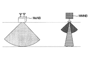
- FIG. 1 is a diagram schematically showing a reach range of a beam (radio signal) according to a frequency. Since a conventional base station (macro base station MeNB) performs radio communication using a low frequency band, the beam reaches farther even if a beam with a wide radiation pattern is used.
- a conventional base station macro base station MeNB
- the base station (small base station MMNB) corresponding to the Massive-MIMO transmission system of this embodiment performs radio communication using a high frequency band
- the macro base station Compared with MeNB the distance which a beam reaches is short.
- the beam radiation pattern width is narrowed by beam forming, even a small base station MMNB using a high frequency band can reach the beam far.
- FIG. 2 is a schematic configuration diagram of the wireless communication system 1 according to the embodiment.
- the radio communication system 1 includes a macro base station MeNB, a small base station MMNB, a central control station MME, and a user apparatus UE.
- the small base station MMNB is a base station that supports the Massive-MIMO transmission scheme.
- the macro base station MeNB forms a macro cell Cm around it, and the small base station MMNB forms a Massive-MIMO cell (MM cell) Cmm around it.
- the frequency band (for example, 10 GHz band) used by the small base station MMNB has a higher frequency and propagation loss than the frequency band (for example, 2 GHz band) used by the macro base station MeNB, so the cell size of the MM cell Cmm is It is smaller than the cell size of the macro cell Cm. Therefore, there is a high possibility that the small base station MMNB and the user apparatus UE are connected by a line-of-sight.
- the MM cell Cmm can overlap with a wireless communicable area using other wireless access technology (Radio Access Technology, RAT) such as the macro cell Cm.
- RAT wireless access technology
- simultaneous connection Multiple Connectivity
- multiple Connectivity using a plurality of radio access technologies is supported for the user apparatus UE located in the overlapping region.
- a control signal from the macro base station MeNB corresponding to a different radio access technology to the user apparatus UE communicating with the small base station MMNB corresponding to the Massive-MIMO transmission scheme.
- a public or local wireless LAN is exemplified.
- the propagation loss is compensated by the gain realized by beam forming.
- a plurality of data streams are spatially multiplexed and transmitted.
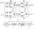
- FIG. 3 is a diagram illustrating an example of a configuration of a transmitter and a receiver in Massive-MIMO adopting fixed beam forming.
- FIG. 3 shows a configuration based on SU-MIMO where there is a single transmitter and a single receiver.
- the precoder and transmit beamformer of the transmitter eg, small base station MMNB
- the receive beamformer and postcoder of the receiver respectively receive and Perform post-coding.
- L T rows and M columns
- N T the number of transmitted beams
- FIGS. 4 shows an equivalent circuit on the transmitter side
- FIG. 5 shows an equivalent circuit on the receiver side.
- An equivalent circuit on the transmitter side corresponds to, for example, an equivalent circuit of a downlink base station
- an equivalent circuit on the receiver side corresponds to, for example, an equivalent circuit of a downlink user apparatus.
- the processing circuit PC T includes an inverse FFT unit 1 that performs inverse fast Fourier transform on the output signal of the digital signal processing circuit DC T , a guard interval insertion unit 2 that inserts a guard interval into the output signal of the inverse FFT unit 1, and a guard interval.
- a DA conversion unit 3 that DA converts the output signal of the insertion unit 2 and an up converter 4 that up-converts the output signal of the DA conversion unit 3 and outputs a high-frequency transmission signal.
- Radio frequency transmission signal is subjected to changes in phase and amplitude is imparted by one of the plurality of variable phase shifters PS, and the amplitude adjuster AA or both, as well as the analog signal processing circuit AC T having adder AD (i.e., after analog transmit beamforming is performed), it is transmitted from the transmitting antenna a T of the N T.
- the analog having relative frequency reception signal received by N R receive antennas A R, a plurality of variable phase shifters PS, the amplitude adjuster AA and the adder AD changes in phase and amplitude is imparted by the signal processing circuit AC R (i.e., analogically reception beam forming is performed).
- Processing circuit PC R includes a down converter 5 for down-converting the signal of the baseband output signal of the analog signal processing circuit AC R, the output signal of the down converter 5 and the AD converter 6 for AD conversion, the AD converter 6 A guard interval removing unit 7 that removes the guard interval from the output signal and an FFT unit 8 that performs fast Fourier transform on the output signal of the guard interval removing unit 7 are provided.
- Digital signal processing circuit DC R is the output signal of the processing circuit PC R, subjected to digitally postcoding (matrix operation), generates a stream of the M (playback).
- N T sufficiently large number of transmission antennas N T to the stream number M to be transmitted (i.e., a M ⁇ N T) is suitable in Massive-MIMO transmission scheme.
- a matrix operation of N T rows and M columns for converting M stream components into N T transmission antenna components prior to transmission of a radio signal is performed. is necessary.
- L T rows and M columns of a precoding matrix are used.
- N T rows L T columns transmit BF weight matrix M stream components are converted into NT transmit antenna components by the matrix operation according to.
- the digital signal processing circuit DC T In the above configuration, at the transmitting side, only the precoding is performed by the digital signal processing circuit DC T. Therefore, compared with the configuration in which digital processing of both the pre-coding and transmission beam forming, on the circuit scale can be reduced and the calculation amount of the digital signal processing circuit DC T, the DA conversion unit 3 (processing circuit PC T) number Can also be reduced. Therefore, the simplification of the configuration and the use of a large number of transmission antennas AT are realized. The same applies to the reception side (postcoding and reception beamforming). Further, when employing a digital fixed beam forming, of FIG. 4, the digital beam forming unit for forming a W T of a subsequent stage to the number 11 of the guard interval insertion section 2 is inserted, out of FIG. 5, AD converter 6 A digital beam forming unit for forming a reception BF weight matrix is inserted in the subsequent stage.
- FIG. 6 is a conceptual diagram of MU-MIMO.
- a small base station MMNB which is one MIMO base station, transmits multiplexed signals simultaneously to a plurality of user apparatuses UE using a plurality of transmission antennas AT . That is, the MIMO base station can perform wireless communication simultaneously with a plurality of users by user multiplexing.
- the channel correlation between a plurality of users is reduced, so that the total communication speed of all user apparatuses UE is improved.
- interference occurs between a plurality of users due to multiplexing of users.
- a desired signal for the first user apparatus UE-1 becomes an interference signal for the second user apparatus UE-2, and vice versa. Therefore, interference control for reducing interference between users is necessary.
- FIG. 7 is a diagram illustrating an example of a configuration of a transmitter and a receiver in Massive-MIMO employing fixed beam forming.
- FIG. 7 shows a configuration based on MU-MIMO with a single transmitter and multiple receivers.
- N U the number of users Total (number receiver)
- M the total number of streams of all users
- a single user is represented by i (1 ⁇ i ⁇ N U )
- the number of streams of the i-th user (i-th user) is M i .
- a precoder and a transmission beamformer of a small base station MMNB that is a transmitter each of a user apparatus UE that is a receiver (first user apparatus UE-1, ..., i-th user apparatus UE-i, ..., About N U th user equipment UE-N U) signal which is addressed to respectively perform the precoding and transmit beamforming.
- Signal to all user equipments UE are added, is transmitted from the transmitting antenna A T of the N T.
- Transmission beam number of total all users is L T
- Each user equipment UE, N R using the reception antenna A R of the receive signal, the receive beamformer and postcoder of each user equipment UE performs receive beamforming and postcoding respectively.
- the precoding process for the i-th user is a signal vector of N R rows and 1 column.
- the above signal vector is expressed by the following equation. Where Is a data signal vector M i rows and one column corresponding to the stream of M i present, Is a zero vector of (N R ⁇ M i ) rows and 1 column. (•) T indicates transposition of a matrix or a vector.
- the transmission BF weight matrix of NT rows and L Ti columns is applied to the signal subjected to the precoding process. Is a process of multiplying by. Note that the NT BF 1 transmission BF weight vector corresponding to each of the L Ti transmission beams is Then, the transmission BF weight matrix is Can be expressed.
- the above precoding processing and transmission beamforming processing (hereinafter, may be collectively referred to as transmission side signal processing) are executed for all users (UE-1,..., UE-i,..., UE-N U ).
- the N T signals for each user obtained as a result of the transmission-side signal processing for all users are added is distributed to the N T adders, it is transmitted from the transmitting antenna A T of the N T. That is, a signal transmitted from a single transmission antenna AT can include signal components for all users.
- a signal transmitted from N T transmission antennas A T is received by each user apparatus UE.
- the signal received by the i-th user apparatus UE-i includes a channel matrix of N R rows and N T columns corresponding to spatial propagation from the small base station MMNB to the user apparatus UE-i. Is multiplied.
- the above channel matrix changes with user apparatuses UE. Therefore, in the entire MU-MIMO system of this example, the entire channel matrix of N R ⁇ N U rows N T columns Is formed.
- N R ⁇ N U denotes a receiving antenna A R number of the entire system.
- the received signal vector received antenna A R receives (details will be described later), N R rows N R rows of the received BF weight matrix Is a process of multiplying by.
- Postcoding processing for the i-th user, to the reception beam forming is performed signal, N R rows N R column postcoding matrix Is a process of multiplying by.
- the first to M i rows are data signal vectors corresponding to the estimated (reproduced) M i streams, and the remaining (M i +1) to N R rows are zero. Is a vector.
- FIG. 8A is a functional block diagram illustrating main components of the small base station MMNB (transmitter) of the embodiment.
- the small base station MMNB includes a data signal generation unit 10, a reference signal generation unit 20, a baseband processing unit 30, a DA conversion unit 40, an RF processing unit 50, a feedback unit 60, a precoding control unit 70, and a transmission BF weight control unit 80. And a storage unit 90.
- the baseband processing unit 30 includes a precoding unit 32, and the RF processing unit 50 includes an up-conversion unit 52 and a transmission beam forming unit 54.
- N T transmit antennas A T are connected to the transmit beamforming unit 54.
- adopted in the small base station MMNB of this embodiment is arbitrary. For example, a single carrier (SC) may be employed, or orthogonal frequency division multiplexing (OFDM) may be employed.
- SC single carrier
- OFDM orthogonal frequency division multiplexing
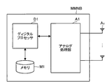
- FIG. 8B shows an example of a circuit configuration of the small base station MMNB.
- the small base station MMNB includes a digital processor D1, a memory M1, an analog processing unit A1, and a transmission antenna AT .
- the digital processor D1 is an element that executes various digital signal processing.
- Functional elements such as the control unit 80 are provided.
- the digital processor D1 is a CPU (Central Processing Unit), for example, and provides the above functional elements by executing a computer program stored in the memory M1.
- the memory M1 can include RAM and ROM.
- the memory M1 functions as the storage unit 90 described above.
- the analog processing unit A1 is an element that executes various analog signal processing.
- the analog processing unit A1 includes the above-described RF processing unit 50 and the like.
- the analog processing unit A1 also includes the DA conversion unit 40 and the AD conversion unit described above that mutually convert a digital signal and an analog signal.
- the data signal generation unit 10 illustrated in FIG. 8A generates a data signal to be included in a transmission signal for the user apparatus UE.
- the data signal generation unit 10 can generate a data signal as a plurality of streams.
- the data signal generating section 10 generates a data signal of the M number of streams corresponding to the N U pieces of user equipment UE (as described above, the number of streams of the i-th user (the i user) it is a M i).
- the reference signal generation unit 20 generates a reference signal to be included in the transmission signal for the user apparatus UE.
- the reference signal includes, for example, channel estimation in each user apparatus UE, measurement of received power in the user apparatus UE, initial synchronization between the user apparatus UE and the small base station MMNB, identification of the small base station MMNB in the user apparatus UE, and beam search It is a signal used for identification of a candidate beam.
- the generated data signal and reference signal are input to the baseband processing unit 30 as a baseband signal.
- the baseband processing unit 30 is an element that processes an input baseband signal (data signal and reference signal).
- the baseband processing unit 30 performs a precoding matrix on the i-th user signal vector.
- the precoding unit 32 performs the above digital precoding on a total of M streams corresponding to all users (UE-1,..., UE-N U ). That is, the precoding unit 32 operates as a N U number of precoder.
- a signal combining a data signal and a reference signal is precoded by the precoding unit 32 and output from the baseband processing unit 30.
- a reference signal that is not precoded is output from the baseband processing unit 30.
- the DA conversion unit 40 converts the digital signal output from the baseband processing unit 30 into an analog signal and outputs the analog signal to the RF processing unit 50.
- the RF processing unit 50 is an element that processes an input analog signal and transmits it from the transmission antenna AT .
- the RF processing unit 50 includes an up-conversion unit 52 that converts an input analog signal into a radio frequency RF signal, and a transmission BF weight matrix for the frequency-converted signal.
- a transmission beam forming unit 54 for performing analog transmission beam forming based on the above. Transmission beam forming unit 54, all users (UE-1, ..., UE -N U) of the total L T of signal corresponding to the total transmit beam, executing the above transmission beam forming. That is, the transmission beam forming unit 54, operates as an N U number of transmit beamformer.
- High frequency transmission signal output from the transmission beam forming unit 54 (the transmit beamformer) is transmitted are added by the N T adders beamforming unit 54 has is transmitted from the transmitting antenna A T of the N T.
- the analog transmission beam forming described above is a process of giving a change in phase and amplitude corresponding to multiplication of a transmission BF weight matrix to an analog signal using the variable phase shifter PS and the amplitude adjuster AA.
- the analog transmission beamforming is performed on the plurality of analog signals transmitted from the plurality of transmission antennas AT so that the phases and amplitudes of the plurality of analog signals are analogized.
- Change. Changes in the phase and amplitude of a plurality of analog signals are equivalent to multiplying a transmission signal vector having a plurality of analog signals as elements by a transmission BF weight matrix.
- the feedback unit 60 is an element that performs control-related communication with each user apparatus UE, and in particular, supplies feedback information from the user apparatus UE to the precoding control unit 70 and the transmission BF weight control unit 80.
- the precoding control unit 70 controls the precoding matrix used in the precoding unit 32.
- the transmission BF weight control unit 80 controls the BF weight used in the transmission beam forming unit 54.
- the BF weight is determined by beam search.
- a plurality of candidate beams that are transmission beam candidates used for radio communication are transmitted from the small base station MMNB to each user apparatus UE, and secondly, each user apparatus UE is associated with each of the plurality of candidate beams.
- the received power is measured, and feedback information including the third measured received power is transmitted from each user apparatus UE to the small base station MMNB.
- the small base station MMNB determines a BF weight based on the feedback information.
- the feedback information includes determination information indicating whether the received power is the desired power or the interference power.
- the candidate beam is suitable for use in radio communication in the user apparatus UE that is the source of the feedback information.
- the candidate beam is not preferably used for radio communication in the user apparatus UE that is the source of feedback information, and interference control is required.
- MU-MIMO when the number of user apparatuses UE communicating with the small base station MMNB increases, the processing load on the small base station MMNB increases. However, it is possible to reduce the processing load by feeding back feedback information including determination information from each user apparatus UE to the small base station MMNB.
- the storage unit 90 stores information related to wireless communication control (for example, a precoding matrix and a transmission BF weight matrix).
- elements that execute digital processing for example, the data signal generation unit 10, the reference signal generation unit 20, the baseband processing unit 30, the feedback unit 60, the precoding control unit 70,
- the transmission BF weight control unit 80 is a functional block realized by a CPU (Central Processing Unit) (not shown) executing a computer program stored in the storage unit 90 and functioning according to the computer program.
- a CPU Central Processing Unit
- FIG. 9A is a functional block diagram illustrating main components of the user apparatus UE (receiver) of the i-th user according to the embodiment.
- the user apparatus UE includes an RF processing unit 110, an AD conversion unit 120, a baseband processing unit 130, a signal analysis unit 140, a transmission / reception characteristic estimation unit 150, a reception BF weight control unit 160, a post coding control unit 170, a measurement unit 180, and a comparison Unit 190, feedback unit 200, and storage unit 210.
- the RF processing unit 110 includes a reception beamforming unit 112 and a down-conversion unit 114, and the baseband processing unit 130 includes a post-coding unit 132.
- N R reception antennas A R are connected to the reception beam forming unit 112.
- FIG. 9B shows an example of a circuit configuration of the user apparatus UE.
- the user equipment UE includes a digital processor D2 and memory M2 and display unit H and the analog processing section A2 and the receiving antenna A R.
- the digital processor D2 is an element that executes various digital signal processing.
- Functional elements (functional blocks) such as the unit 180, the comparison unit 190, and the feedback unit 200 are provided.
- the digital processor D2 is, for example, a CPU, and provides the above functional elements by executing a computer program stored in the memory M2.
- the memory M2 can include RAM and ROM.
- the memory M2 functions as the storage unit 210 described above.
- the analog processing unit A2 is an element that executes various analog signal processing.
- the analog processing unit A2 includes the above-described RF processing unit 50 and the like.
- the analog processing unit A2 also includes the above-described AD conversion unit 120 and DA conversion unit that mutually convert a digital signal and an analog signal.
- the measurement unit 180 is included in the analog processing unit A2.
- the display unit H is configured by, for example, a liquid crystal display device or an organic EL display device.
- the display unit H may be configured with a touch panel, and may display an image or accept an input operation of a user.
- RF processing unit 110 is an element for processing a signal in which a plurality of receiving antennas A R has received.
- the RF processing unit 110 receives the received BF weight matrix with respect to the received signal.
- the reception beam forming unit 112 that performs analog reception beam forming based on the above, and the down conversion unit 114 that converts the frequency of the input signal into a baseband signal and outputs the baseband signal.
- the above-described analog reception beamforming is a process of giving a change in phase and amplitude corresponding to multiplication of the reception BF weight matrix to an analog signal using the variable phase shifter PS and the amplitude adjuster AA.
- the phase and amplitude of a plurality of analog signals in an analog manner Change are equivalent to multiplying a reception signal vector having a plurality of analog signals as elements by a reception BF weight matrix.
- reception BF weight matrix is a unit matrix
- reception beam forming section 112 and reception weight control section 160 may be omitted.
- the AD conversion unit 120 converts the analog signal output from the RF processing unit 110 into a digital signal and outputs the digital signal to the baseband processing unit 130.
- the baseband processor 130 is an element for restoring the M i book streams by processing the input baseband signals.
- the baseband processing unit 130 applies a post-coding matrix to the signal output from the AD conversion unit 120. Is provided with a post coding unit 132 that performs digital post coding (matrix operation). By the above post-coding, M i the streams are reproduced. Regenerated M i This stream is analyzed are input to the signal analysis unit 140.
- the transmission / reception characteristic estimation unit 150 performs transmission / reception characteristic estimation described later.
- the reception BF weight control unit 160 controls the BF weight used in the reception beamforming unit 112.
- the post coding control unit 170 controls the post coding matrix used in the post coding unit 132.
- the measurement unit 180 measures an index related to communication quality and outputs a measurement result to the feedback unit 200.
- This index may be any index as long as it indicates the degree of communication quality.
- RSRP Reference Signal Received Power
- SINR Signal-to-Interference Noise Power Ratio
- E-UTRA Carrier RSSI Receiveived Signal Strength Indicator
- RSRQ Reference Signal Received Quality
- RSSI means the total received power of all signals such as a desired signal from the serving cell, an interference signal from another cell, and a noise signal due to thermal noise.
- RSRP means the received power of the reference signal
- SINR is the ratio of received signal power to interference and noise power in consideration of neighboring cell interference.
- received power RSRP and / or RSSI
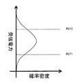
- the comparison unit 190 compares the received power measured by the measurement unit 180 with each of the first threshold value REF1 and the second threshold value REF2, and outputs the comparison result to the feedback unit 200.
- FIG. 10 shows the relationship between the received power, the first threshold value REF1, the second threshold value REF2, and the feedback information. Focusing on the received power for each of a plurality of candidate beams transmitted from the small base station MMNB, because the reception level should be the desired power because the reception level is high, and because the reception level is medium Since the reception power should be interference power and the reception level is low, the reception power can be broadly divided into interference power that can ignore the influence of the reception power on communication. .
- the first threshold value REF1 is set to a value that can determine whether or not the interference power can ignore the influence of the received power on the communication.
- the second threshold value REF2 is set to a value that can determine whether the received power is the desired power or the interference power.
- the feedback unit 200 is an element that performs communication related to control with the small base station MMNB.
- the feedback information from the transmission / reception characteristic estimation unit 150, the reception BF weight control unit 160, and the measurement unit 180 is transmitted to the small base station MMNB.
- Send Further, based on the comparison result of comparison section 190, feedback section 200 transmits the received power to small base station MMNB as feedback information related to interference power when the received power is greater than or equal to first threshold value REF1 and less than second threshold value REF2.
- first threshold value REF1 first threshold value
- REF2 second threshold value
- the received power is transmitted as feedback information regarding the desired power to the small base station MMNB.
- the feedback information is transmitted to the small base station MMNB.
- the feedback information regarding the received power generated by the feedback unit 200 includes determination information indicating whether the received power is interference power or desired power, and received power information indicating the received power. That is, the feedback unit 200 transmits the received power to the small base station MMNB as feedback information related to the interference beam when the received power (an index related to communication quality) is not less than the first threshold REF1 and less than the second threshold REF2, and the received power is When it is equal to or greater than the second threshold REF2, the received power is transmitted to the small base station MMNB as feedback information regarding the desired beam.
- the presence or absence of transmission of feedback information is determined based on the received power, and feedback information to be transmitted is generated.
- the feedback information to be transmitted may be generated by determining whether or not the feedback information is transmitted based on other indicators relating to communication quality.
- the storage unit 210 stores information related to wireless communication control (for example, a post-coding matrix, a reception BF weight matrix, a first threshold value REF1, and a second threshold value REF2).
- information related to wireless communication control for example, a post-coding matrix, a reception BF weight matrix, a first threshold value REF1, and a second threshold value REF2.
- elements that perform digital processing for example, the baseband processing unit 130, the signal analysis unit 140, the transmission / reception characteristic estimation unit 150, the reception BF weight control unit 160, and the post coding control unit 170).
- the comparison unit 190, the feedback unit 200, and the like) are functional blocks that are realized when a CPU (not shown) executes a computer program stored in the storage unit 210 and functions according to the computer program.
- the precoding control unit 70 Each precoding matrix that satisfies By setting, all off-diagonal components (interference components) of the above matrix (2) (I.e., block diagonalization of the matrix (2)).
- the received signal vector of the i-th user is It is expressed. That is, each precoding matrix in which the precoding control unit 70 diagonalizes the matrix (2).
- a channel matrix corresponding to the user apparatus UE-i Channel matrix other than (Channel response) can be zero (ie, multiple users of MU-MIMO can be orthogonalized).
- a received signal vector that does not include an interference signal component can be obtained for the i-th user.
- the precoding control unit 70 performs the above-described matrix (2).
- the transmission BF weight matrix and the channel matrix are treated as a unit.
- the matrix May be referred to as an “equivalent channel matrix”.
- Equivalent channel matrix including transmission BF weight matrix corresponding to i-th user Of which an equivalent channel matrix including a channel matrix corresponding to the i-th user
- a set of equivalent channel matrices (excluded channel matrices) of N R ⁇ (N U ⁇ 1) rows L Ti columns, excluding is defined as follows.
- the above excluded channel matrix is a transmission BF weight matrix corresponding to the i-th user.
- Channel matrix corresponding to users other than the i-th user It can also be expressed as a set including a plurality of equivalent channel matrices obtained by multiplying each.
- the left singular matrix I is a unitary matrix of N R ⁇ (N U ⁇ 1) rows N R ⁇ (N U ⁇ 1) columns.
- Right singular matrix Is a unitary matrix of L Ti rows and L Ti columns.
- Singular value matrix Is Is a matrix of N R ⁇ (N U ⁇ 1) rows L Ti columns having 0 as a diagonal component and 0 as a non-diagonal component.
- Is a matrix of L Ti rows N R columns Is a matrix of L Ti rows (L Ti ⁇ N R ) columns.
- Is the excluded channel matrix This is an eigenvector (first eigenvector) corresponding to the noise subspace on the transmitter side, and is used for block diagonalization in this embodiment.
- Is Is an eigenvector (second eigenvector) corresponding to the signal subspace on the transmitter side, and is used for block diagonalization in this embodiment.
- a precoding matrix for the i-th user is obtained as in the following Expression (7).
- the post-coding matrix of the i-th user is obtained as in the following equation (8).
- Non-diagonal component of matrix (2) above Substituting the above equation (7) into Is obtained.
- the above non-diagonal components are based on the relationship of equation (5). It becomes.
- the precoding control unit 70 sets the precoding matrix of each user as in Expression (7), whereby the matrix (2) is block-diagonalized and Expression (3) is established ( That is, a plurality of users targeted for MU-MIMO are orthogonalized to each other).
- equation (3) can be further modified as follows.
- precoding control unit 70 N U precoding matrix To determine the overall channel matrix in the MU-MIMO system The block diagonalization is realized. In other words, the precoding matrix As long as is determined as described above, the transmission BF weight matrix And received BF weight matrix Can be arbitrarily determined.
- the transmission BF weight control unit 80 transmits the transmission BF weight matrix of the i-th user. May be determined to be a value that maximizes the received power of the i-th user based on feedback information, or to a value that maximizes the signal-to-interference ratio of the i-th user. It may be determined, or may be determined to a value that maximizes the channel capacity (capacity) of the entire system. As described above, since the feedback information includes determination information indicating whether the received power is the desired power or the interference power, the transmission BF weight control unit 80 determines whether the received power is the desired power or the interference. There is no need to determine whether it is electric power. Therefore, the processing load on the transmission BF weight control unit 80 can be reduced.
- the transmission BF weight control unit 80 transmits the transmission BF weight matrix of the i-th user. May be generated using a steering vector indicating a phase and amplitude change caused by processing performed by the variable phase shifter PS and the amplitude adjuster AA, or may be generated based on DFT (Discrete Fourier Transform) precoding. Alternatively, a transmission beam in which a plurality of users are mutually orthogonalized may be generated using a Butler matrix.
- DFT Discrete Fourier Transform
- the received BF weight matrix of the i-th user Is determined as a unit matrix of N R rows and N R columns. That is, a configuration in which no BF weight is applied on the receiving side is adopted.
- FIG. 11 is an operation flow of transmission BF weight matrix determination processing.
- the small base station MMNB transmits a transmission BF weight vector corresponding to the l-th transmission beam.
- Candidates ie, combinations of ⁇ and ⁇ , which are steering vector variables
- S10 Candidates
- S20 reference signals of L Ti streams orthogonal to each other
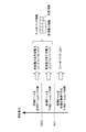
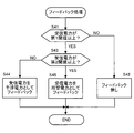
- FIG. 12 is a flowchart showing the contents of the feedback process.
- the comparison unit 190 determines whether or not the received power is greater than or equal to the first threshold REF1 (S41). If the received power is less than the first threshold REF1, the determination condition is denied (S41: NO), and the feedback unit 200 ends the process without feeding back the fadeback information to the small base station MMNB (S42).
- the comparison unit 190 determines whether or not the received power is greater than or equal to the second threshold REF2 (S42). When the received power is less than the second threshold REF2, the determination condition is denied (S42: NO), and the feedback unit 200 feeds back to the small base station MMNB that the received power is interference power (S44). On the other hand, if the received power is greater than or equal to the second threshold REF2, the determination condition is affirmed (S43: YES), and the feedback unit 200 feeds back the received power to the small base station MMNB as the desired power (S45).
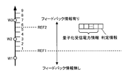
- FIG. 13 is an explanatory diagram showing a specific example of feedback of received power when a certain candidate beam is transmitted.
- the user apparatuses UE-1, UE-2, and UE-3 are included in the MM cell Cmm of the small base station MMNB.
- received power is measured in each of user apparatuses UE-1 to UE-3.
- the received power measured in the user apparatus UE-1 is W1
- the received power measured in the user apparatus UE-2 is W2
- the received power measured in the user apparatus UE-3 is W3.
- the received power W1 measured in the user apparatus UE-1 is less than the first threshold value REF1
- feedback information is not fed back from the user apparatus UE-1 to the small base station MMNB.
- the received power W2 measured in the user apparatus UE-2 is not less than the first threshold REF1 and less than the second threshold REF2
- the received power W2 is fed back from the user apparatus UE-2 to the small base station MMNB as interference power.
- the received power W3 measured in the user apparatus UE-3 is equal to or greater than the second threshold REF2, the received power W3 is fed back from the user apparatus UE-3 to the small base station MMNB as desired power.
- the first threshold value REF1 is set to a value that can determine whether or not the interference power can ignore the influence of the received power on the communication. Therefore, there is no problem in determining the BF weight even if the feedback information is not transmitted to the small base station MMNB when the received power is less than the first threshold REF1.
- feedback is required from a plurality of user apparatuses UE to the small base station MMNB. However, the amount of feedback information can be reduced by not transmitting feedback information.
- the small base station MMNB repeats the above steps until selection of all steering vector candidates is completed (S50: NO).
- the transmission BF weight vector candidates (that is, combinations of ⁇ and ⁇ ) are preferably selected while shifting in units of predetermined difference values ⁇ and ⁇ . This process, as shown in FIG. 14, a plurality of candidate beam shift in the horizontal direction and the vertical direction is transmitted to the user equipment UE-1 ⁇ UE-N U .
- the small base station MMNB When selection of all the steering vector candidates is completed (S50: YES), the small base station MMNB receives a reference signal corresponding to each of the transmission BF weight vector candidates transmitted from the user apparatus UE and fed back. Based on power, the optimal transmit BF weight vector corresponding to the l th transmit beam Candidates (ie, combinations of ⁇ and ⁇ ) are determined according to a certain criterion (S60). For example, a criterion such as maximizing the capacity of the entire system or increasing the throughput of a specific user apparatus UE may be adopted.
- the transmission BF weight matrix of the i-th user Is determined.
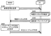
- FIG. 15 is an operation flow showing precoding matrix and postcoding matrix determination processing according to the present embodiment.
- each user's transmission BF weight matrix And received BF weight matrix Is determined in advance by, for example, the above-described method (the method described in “1 (3) -3. Determination of Weight Matrix”).
- the received BF weight matrix of this embodiment Is the identity matrix.
- the transmission BF weight control unit 80 of the small base station MMNB sends the transmission BF weight matrix of all users to the transmission beamforming unit 54 with respect to the reference signal RS. To execute the analog transmit beamforming with, it is transmitted from the transmitting antenna A T of the N T (S100).
- the reference signal RS transmitted from the transmission antenna AT corresponds to each user apparatus UE by propagating a space (propagation path) toward each user apparatus UE (UE-1,..., UE-N U ).
- the i-th user equipment UE-i receives BF weight controller 160 of the receiving beam forming unit 112, with respect to the reference signal RS received by the receiving antenna A R, the reception BF weight matrix is the identity matrix Is used to perform analog receive beamforming (ie, no receive weight is applied).
- the reference signal RS received by the reception beamforming unit 112 is input to the transmission / reception characteristic estimation unit 150 through the down-conversion unit 114 and the AD conversion unit 120.
- the transmission / reception characteristic estimation unit 150 uses the input reference signal RS to convert the equivalent channel matrix Is estimated (S200).
- the above equivalent channel matrix is a characteristic matrix indicating a change in signal due to transmission beamforming and spatial propagation.
- the above estimation of the equivalent channel matrix is performed in the same manner as general channel estimation. For example, estimation using the least square method is possible.
- the estimated equivalent channel matrix is fed back from the i-th user apparatus UE-i via the feedback unit 200 (S300) and received by the small base station MMNB.
- the size of the channel matrix of the i user is a N T ⁇ N R.
- the size of the equivalent channel matrix of the i-th user is L Ti ⁇ N R , the amount of feedback information can be reduced compared to feeding back the channel matrix. As a result, overhead associated with transmission of feedback information can be reduced, and data transmission throughput can be improved.
- the small base station MMNB has received all combinations of equivalent channel matrices. To get.
- the precoding control unit 70 of the small base station MMNB uses all combinations of the acquired equivalent channel matrixes to exclude all user excluded channel matrices. Generates the aforementioned method according to (approach described in "1 (3) -2. Calculation of precoding matrices realizing the block diagonalization"), N U precoding matrix And postcoding matrix Is determined (S400).
- determination of the precoding matrix and the postcoding matrix is executed by the small base station MMNB (precoding control unit 70).
- the determined post-coding matrix is notified to the corresponding user apparatus UE via the feedback unit 60, respectively.
- the amount of feedback information transmitted to the small base station can be reduced.
- the feedback information includes determination information indicating whether the received power is the interference power or the desired power, the small base station MMNB can reduce the processing load for determining the transmission BF weight. Is possible.
- the received power is fed back from the user apparatus UE to the small base station MMNB.
- the information to be fed back is not limited to the received power value.
- the amount of feedback information may be reduced by quantizing the received power in the user apparatus UE and feeding back only the index.
- the user equipment receives feedback information including quantized received power information indicating the quantized received power obtained by quantizing the received power and determination information indicating whether the received power is interference power or desired power. The UE may generate this, and the user apparatus UE may feed back this to the small base station MMNB.
- received power equal to or higher than the first threshold REF1 may be quantized in nine steps.
- the target of comparison with the first threshold value REF1 for determining whether or not to perform feedback may be received power or quantized received power.
- the comparison target with the second threshold value REF2 for determining whether the received power is the desired power or the interference power may be the received power or the quantized received power. May be.
- the quantized received power is “7”. Since the quantized received power “7” is equal to or greater than the second threshold REF2, the quantized received power “7” is fed back as the desired power. According to this modification, the amount of feedback information can be reduced, and the overall system overhead can be reduced.
- the user apparatus UE makes interference power a problem in communication with one small base station MMNB in which radio communication is established.
- the user apparatus UE may be interfered by a transmission beam from another small base station MMNB. Therefore, the user apparatus UE may generate feedback information as follows and feed it back to the small base station MMNB in which wireless communication is established.
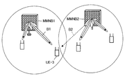
- the small base station MMNB in which wireless communication is established is referred to as a first small base station MMNB1, and the other small base stations MMNB are referred to as second small base stations MMNB2. For example, as illustrated in FIG.
- the user apparatus UE-3 is located near the boundary between the cell Cmm1 of the first small base station MMNB1 and the cell Cmm2 of the second small base station MMNB2. In this case, the user apparatus UE-3 receives the desired beam B1 from the first small base station MMNB1 and receives the interference beam B2 from the second small base station MMNB2.
- the measurement unit 180 transmits a transmission beam (in this example, an interference beam B2) transmitted from the second small base station MMNB2. ), The other-cell interference power is measured.
- a transmission beam in this example, an interference beam B2
- the comparison unit 190 compares the third threshold value REF3 with the other cell interference power and outputs the comparison result to the feedback unit 200.
- the feedback unit 200 provides feedback information including other cell interference information indicating that there is interference from the second small base station MMNB2 to the first small base station MMNB1 when the other cell interference power is greater than or equal to the third threshold REF3.
- the feedback unit 200 does not transmit feedback information to the first small base station MMNB1.
- the operation of the user apparatus UE when the feedback information is not transmitted to the first small base station MMNB1 is the same as that in the above-described embodiment. That is, when a plurality of candidate beams are transmitted from the first small base station MMNB1, the user apparatus UE determines whether or not to transmit feedback information based on the received power. Feedback information including determination information indicating interference power or desired power is transmitted.
- the other-cell interference information identifies information for identifying the second small base station MMNB2 and a transmission beam (in this example, interference beam B2) from the second small base station MMNB2 that causes interference.
- Information is preferably included.
- the feedback information preferably includes other cell interference power information indicating the other cell interference power.
- the third threshold value REF3 is set to a value that can determine whether or not the influence of the transmission beam from the second small base station MMNB2 on the communication quality can be ignored, and is stored in the storage unit 210. Note that the third threshold value REF3 may be set regardless of the first threshold value REF1 and the second threshold value REF2 described above. For example, the third threshold value REF3 may be set to be equal to or higher than the first threshold value REF1.
- the measurement unit 180 is transmitted from the second small base station MMNB2.
- the transmission beam may be configured to measure the interference power of other cells.
- the comparison unit 190 compares the third threshold value REF3 with the other cell interference power and outputs the comparison result to the feedback unit 200.
- the feedback unit 200 changes the feedback information when feeding back a plurality of candidate beams from the first small base station MMNB1 to the first small base station MMNB1.
- the feedback unit 200 generates feedback information including corrected received power information related to the corrected received power obtained by correcting the received power according to the interference power of other cells instead of the received power information, and the first small base station Send to MMNB1.
- the corrected received power information may be the corrected received power itself, or information obtained by quantizing the corrected received power.
- the received power fed back as the desired power is preferably corrected to a smaller power as the other cell interference power increases.
- the first small base station MMNB1 adjusts the transmission BF weight and maintains the radio quality. With this process, it is possible to increase the gain of the desired beam for the user apparatus UE even if there is other-cell interference power.
- the first threshold value REF1 and the second threshold value REF2 are stored in the storage unit 210. However, these may be arbitrarily set for each user apparatus UE. Moreover, this setting may be set by designation from the small base station MMNB, or may be set uniquely in the user apparatus UE.
- FIG. 18 shows an example of the relationship between received power and probability density.
- the second threshold value REF2 is lowered, the number of beams fed back as desired beams among the plurality of candidate beams increases. For this reason, the BF gain can be increased.
- increasing the second threshold value REF2 increases the number of beams that are fed back as interference beams among the plurality of candidate beams. For this reason, the interference control in the small base station MMNB can be strengthened.
- the user apparatus UE may include a setting unit that sets the second threshold value REF2 to a value such that the number of candidate beams that are targets of feedback information regarding the desired power is equal to or greater than the number corresponding to the desired communication speed. .
- the user apparatus UE can control the BF gain according to a desired communication speed. The processing load in the small base station MMNB can be reduced.
- the user apparatus UE may include a setting unit that sets at least one of the first threshold value REF1 and the second threshold value REF2 according to average received power.
- the user apparatus UE may include a setting unit that sets at least one of the first threshold value REF1 and the second threshold value REF2 in order to control interference according to the distribution of received power.
- the transmission / reception characteristic estimation unit 150 estimates the equivalent channel matrix using the input reference signal RS.
- the transmission BF weight matrix may be determined after estimating the channel matrix instead of the equivalent channel matrix.
- the estimated channel matrix is fed back from the user apparatus UE to the small base station MMNB.
- the user apparatus UE may quantize and feed back the elements of the channel matrix.
- the user apparatus UE feeds back elements of the equivalent channel matrix.
- elements of the equivalent channel matrix may be quantized and fed back. The amount of feedback information can be reduced by quantizing the channel matrix or the equivalent channel matrix.
- the transmission beam number LTi may be set dynamically.
- the transmission beam number L Ti may be set to a number that makes the communication speed of the i-th user equal to or greater than a certain value, or a number that improves the communication speed of the entire system (preferably, maximizes the communication speed). May be set).
- the number of transmission beams L Ti may be set to a number that further improves the communication speed as compared with the case where the number of transmission beams L Ti is fixedly set, and the capacity of the i-th user is increased. It may be set to the number to be (preferably the number that maximizes the capacity).
- MCS Modulation and Coding Scheme
- control information between the small base station MMNB and the user apparatus UE can be executed by an arbitrary route. For example, when a radio link is established between the small base station MMNB and the user apparatus UE, control information may be exchanged by directly transmitting and receiving radio signals. Moreover, when the above radio link is not established, the small base station MMNB and the user apparatus UE may transmit / receive control information via the macro base station MeNB.
- Transmission beam forming section 54 of the small base station MMNB may be a Furuare type structure in which one transmit beam is generated using all the transmission antennas A T of the N T, (N T / L T) present using transmission antennas a T may be a subarray type structure in which one transmit beam is generated. In any configuration, the user multiplexing of the above embodiment is realized.
- the user apparatus UE is an arbitrary apparatus capable of wireless communication with a base station (macro base station MeNB and / or small base station MMNB) in the network.
- the user apparatus UE may be a mobile phone terminal such as a feature phone or a smartphone, a tablet terminal, a desktop personal computer, a notebook personal computer, a UMPC (Ultra-Mobile Personal Computer), It may be a game machine or other wireless terminal. Further, it is needless to say that the user apparatus UE may apply the above-described communication not only to wireless communication with the small base station MMNB but also to simple wireless communication with the base station.
- Each function executed by the CPU in each element (user apparatus UE and small base station MMNB) in the wireless communication system 1 may be executed by hardware instead of the CPU, for example, an FPGA (Field Programmable Gate Array) Or a programmable logic device such as a DSP (Digital Signal Processor).
- FPGA Field Programmable Gate Array
- DSP Digital Signal Processor
Landscapes
- Engineering & Computer Science (AREA)
- Signal Processing (AREA)
- Computer Networks & Wireless Communication (AREA)
- Physics & Mathematics (AREA)
- Quality & Reliability (AREA)
- Electromagnetism (AREA)
- Mathematical Physics (AREA)
- Mobile Radio Communication Systems (AREA)
- Radio Transmission System (AREA)
Abstract
ユーザ装置は、複数の候補ビームの各々について、通信品質に関する指標を測定する測定部と、第1閾値および第2閾値の各々と指標とを比較する比較部と、比較部の比較結果に基づいて、指標が第1閾値以上第2閾値未満の場合には指標を干渉ビームに関するフィードバック情報として基地局に送信し、指標が第2閾値以上の場合には指標を所望ビームに関するフィードバック情報として基地局に送信し、指標が第1閾値未満の場合にはフィードバック情報を基地局に送信しないフィードバック部と、を備える。
Description
本発明は、ユーザ装置および基地局に関する。
無線通信の分野において、近年、送信機側と受信機側との双方で複数のアンテナを用いて送受信を実行することにより、信号伝送の高速化および高品質化を実現するMIMO(Multiple-Input and Multiple-Output)技術が活用されている。MIMO技術は、単一のユーザ(受信機)を対象とするSU-MIMO(Single User MIMO)と、複数のユーザ(受信機)を対象とするMU-MIMO(Multiple User MIMO)とを含む。
また、信号伝送の更なる高速化と干渉低減とを図るために、アンテナの小型化と広い帯域幅の確保とが可能な高周波数帯(例えば、10 GHz以上)において、大量のアンテナ素子(例えば、100素子以上)を使用したMassive-MIMO伝送方式が検討されている(例えば、特許文献1)。
Massive-MIMOにおいては、従来のMIMOと比較して、大量のアンテナ素子を用いた高度なビームフォーミング(Beam Forming,BF)が実現される。ビームフォーミングは、複数のアンテナ素子を制御することによりビーム(送信アンテナに対応する送信ビーム、または受信アンテナに対応する受信ビーム)の指向性および/または形状を制御する技術である。MIMOでは、各アンテナ素子について位相および振幅の制御が可能であるので、使用されるアンテナ素子の数が多いほどビーム制御の自由度が高まる。
ビームフォーミングの一態様として、固定ビームフォーミングが例示される。固定ビームフォーミングにおいては、事前に準備された複数のビームフォーミングウェイトの候補から、使用すべきビームフォーミングウェイト(固定ビーム)が選択される。固定ビームフォーミングでは、固定ビームを制御するビームフォーミングと、複数ストリーム間多重の補償を実現するコーディング(送信側でのプリコーディングおよび受信側でのポストコーディング)とが個別に実行される。上述したビームフォーミングおよび複数ストリーム間多重の補償を実現するコーディングのためには、ユーザ装置から基地局に各種の情報をフィードバックする必要がある。
しかしながら、MU-MIMOでは、同時通信を行うユーザ装置が増加するにつれてフィードバックの情報量が増加する。特許文献2には、ユーザ装置において、基地局からの信号のRSSIを測定し、RSSIが閾値以上であると判断した場合、チャネル状態の推定を行い、チャネル状態情報を基地局にフィードバックする一方、RSSI値が閾値未満であると判断した場合、基地局にチャネル状態情報をフィードバックしない技術が開示されている。この技術によれば、ユーザ装置から基地局へのフィードバックの情報量を低減することができる。
ところで、MU-MIMOでは、ユーザ装置において基地局からの送信ビームを干渉ビームとして取り扱うのか、あるいは所望ビームとして取り扱うのかによって、ビームフォーミングおよびコーディングが相違する。
しかしながら、従来の技術では、ユーザ装置から基地局へのフィードバックの情報量を低減できても、送信ビームが干渉ビームとなるか所望ビームとなるかは、ユーザ装置からフィードバックされる情報に基づいて、基地局が判断する必要があった。複数のユーザ装置から送信されるフィードバックは、基地局に大きな処理負荷を発生させるといった問題があった。
本発明は、上述した事情に鑑みてなされたものであり、MU-MIMOにおいて、フィードバックの情報量を低減しつつ、基地局の処理負荷を低減することを解決課題とする。
本発明のユーザ装置は、MU-MIMO通信方式を用いて無線通信を実行する基地局から送信され、送信ビームフォーミングのための複数の候補ビームを受信するユーザ装置であって、前記複数の候補ビームの各々について、通信品質に関する指標を測定する測定部と、第1閾値および当該第1閾値よりも大きい第2閾値の各々と前記指標とを比較する比較部と、前記比較部の比較結果に基づいて、前記指標が前記第1閾値以上前記第2閾値未満の場合には前記指標を干渉ビームに関するフィードバック情報として前記基地局に送信し、前記指標が前記第2閾値以上の場合には前記指標を所望ビームに関するフィードバック情報として前記基地局に送信し、前記指標が前記第1閾値未満の場合にはフィードバック情報を前記基地局に送信しないフィードバック部と、を備える。
本発明の基地局は、MU-MIMO通信方式を用いて、複数のユーザ装置と無線通信を実行可能な基地局であって、M(Mは1以上の整数)本のストリームに対して、プリコーディングウェイト行列を用いてディジタルプリコーディングを施すプリコーディング部と、前記ディジタルプリコーディングが施された後の信号に対して、送信ビームフォーミングウェイト行列に相当する位相および振幅の変化を付与する送信ビームフォーミングを施す送信ビームフォーミング部と、前記送信ビームフォーミングが施された信号を送信するとともに、前記複数のユーザ装置の各々から送信された前記フィードバック情報を受信する複数のアンテナと、前記送信ビームフォーミング部を制御する送信ビームフォーミングウェイト制御部と、を備え、送信ビームフォーミングウェイト制御部は、前記複数の候補ビームの各々に対応する送信ビームフォーミングウェイト行列を選択して、選択した送信ビームフォーミングウェイト行列に相当する位相および振幅の変化を付与する送信ビームフォーミングを、前記送信ビームフォーミング部に実行させ、前記複数のユーザ装置の各々に対応する前記フィードバック情報に基づいて、M本のストリームを送信するための送信ビームフォーミングウェイト行列を決定し、決定した送信ビームフォーミングウェイト行列に相当する位相および振幅の変化を付与する送信ビームフォーミングを、前記送信ビームフォーミング部に実行させる。
本発明によれば、フィードバックの情報量を低減しつつ、基地局の処理負荷を低減する。
1. 実施形態
1(1). Massive-MIMO伝送
本発明の実施形態に係るMassive-MIMO伝送方式について説明する。基地局が多数の送信アンテナATを用いて無線通信を実行するMassive-MIMO伝送方式においては、多重化による高い無線通信速度(データレート)が実現される。また、多数の送信アンテナATを用いることにより、ビームフォーミングを行う際のアンテナ制御の自由度が高まるため、従来よりも高度なビームフォーミングが実現される。そのため、干渉量の低減および/または無線リソースの有効利用が実現される。
1(1). Massive-MIMO伝送
本発明の実施形態に係るMassive-MIMO伝送方式について説明する。基地局が多数の送信アンテナATを用いて無線通信を実行するMassive-MIMO伝送方式においては、多重化による高い無線通信速度(データレート)が実現される。また、多数の送信アンテナATを用いることにより、ビームフォーミングを行う際のアンテナ制御の自由度が高まるため、従来よりも高度なビームフォーミングが実現される。そのため、干渉量の低減および/または無線リソースの有効利用が実現される。
なお、Massive-MIMOに適応した基地局が備える送信アンテナATの数は、以下に限定されるものではないが、32本以上、64本以上、96本以上、100本以上、128本以上、192本以上、200本以上、256本以上、500本以上、512本以上、1000本以上、または1024本以上であると好適である。
Massive-MIMO伝送方式において、高周波数帯(例えば、10 GHz以上の周波数帯)が使用されると好適である。高周波数帯では、低周波数帯と比較して、広い帯域幅(例えば、200 MHz以上)の無線リソースを確保しやすい。また、アンテナ素子の大きさは信号の波長に比例することから、無線信号の波長が相対的に短い高周波数帯を用いる場合には、アンテナをより小型化することが可能である。その一方で、周波数が高いほど伝搬損失が増大するため、仮に同じ送信電力で基地局から無線信号を送信しても、高周波数帯を用いた場合には、低周波数帯を用いる場合と比較して、移動局における受信信号強度が低下する結果となる。
しかしながら、以上のような、高周波数帯を用いることによる受信信号強度の低下は、ビームフォーミング利得により補償可能である。図1は、周波数に応じたビーム(無線信号)の到達範囲を模式的に示す図である。従来の基地局(マクロ基地局MeNB)は低周波数帯を用いて無線通信を行うので、幅の広い放射パターンのビームを用いてもより遠くまでビームが到達する。
他方、本実施形態のMassive-MIMO伝送方式に対応する基地局(スモール基地局MMNB)は高周波数帯を用いて無線通信を行うので、幅の広い放射パターンのビームを用いる場合にはマクロ基地局MeNBと比較してビームの到達する距離が短い。ところが、ビームフォーミングによってビームの放射パターンの幅を狭くする場合には、高周波数帯を用いるスモール基地局MMNBであっても遠くまでビームを到達させることが可能である。
図2は、実施形態に係る無線通信システム1の概略構成図である。無線通信システム1は、マクロ基地局MeNB、スモール基地局MMNB、中央制御局MME、およびユーザ装置UEを備える。スモール基地局MMNBは、Massive-MIMO伝送方式に対応する基地局である。
マクロ基地局MeNBはその周囲にマクロセルCmを形成し、スモール基地局MMNBはその周囲にMassive-MIMOセル(MMセル)Cmmを形成する。スモール基地局MMNBが用いる周波数帯(例えば、10 GHz帯)は、マクロ基地局MeNBが用いる周波数帯(例えば、2 GHz帯)よりも周波数が高く伝搬損失も大きいので、MMセルCmmのセルサイズはマクロセルCmのセルサイズよりも小さい。そのため、スモール基地局MMNBとユーザ装置UEとは見通し線(line-of-sight)で接続される可能性が高い。
図2に示されるように、MMセルCmmは、マクロセルCmなど他の無線アクセス技術(Radio Access Technology, RAT)による無線通信可能エリアとオーバーラップすることが可能である。結果として、オーバーラップする領域に位置するユーザ装置UEに対しては、複数の無線アクセス技術による同時接続(Multiple Connectivity)がサポートされる。
さらに、Massive-MIMO伝送方式に対応するスモール基地局MMNBと通信中のユーザ装置UEに対して、異なる無線アクセス技術に対応するマクロ基地局MeNBから制御信号を送信することも可能である。なお、他の無線アクセス技術として、公衆またはローカルの無線LANが例示される。
前述の通り、高周波数帯域を用いるMassive-MIMO伝送において、ビームフォーミングにより実現される利得によって伝搬損失が補償されると好適である。また、さらなる高速無線通信を実現するために、複数のデータストリームが空間的に多重されて伝送されると好適である。以上のような多重伝送においては、ビームフォーミングによるビーム自体の制御のみならず、プリコーディングによるストリーム間多重の補償が実現されるとより好適である。
図3は、固定ビームフォーミングを採用したMassive-MIMOにおける送信機および受信機の構成の一例を示す図である。図3は、単一の送信機と単一の受信機とが存在するSU-MIMOに基づく構成を示す。送信機(例えば、スモール基地局MMNB)のプリコーダおよび送信ビームフォーマがそれぞれプリコーディングおよび送信ビームフォーミングを実行し、受信機(例えば、ユーザ装置UE)の受信ビームフォーマおよびポストコーダがそれぞれ受信ビームフォーミングおよびポストコーディングを実行する。
数学的には、プリコーディング処理は、M本(Mは1以上の自然数,例えばM=16)のストリームを表すM行1列の信号ベクトル

に対して、LT行M列(LTは送信ビーム数)のプリコーディング行列

を乗算する処理である。送信ビームフォーミング処理は、プリコーディングが施された信号に対して、NT行LT列(NTは送信アンテナ数,例えばNT=256)の送信BF(ビームフォーミング)ウェイト行列

を乗算する処理である。送信ビームフォーミング後、送信アンテナATから送信された信号に対して、空間の伝搬に対応するNR行NT列(NRは受信アンテナ数,例えばNR=16)のチャネル行列

が乗算される。受信ビームフォーミング処理は、受信アンテナARで受信された信号に対して、LR行NR列(LRは受信ビーム数)の受信BFウェイト行列

を乗算する処理である。ポストコーディング処理は、受信ビームフォーミングが施された信号に対して、M行LR列のポストコーディング行列

を乗算する処理である。以上から、ポストコーディング後のM行1列の信号ベクトル

は、以下の数式で表現される。

なお、以上の数式において加算される別項である

は、LR行1列の雑音ベクトルである。
本実施形態では、Massive-MIMO伝送のより好適な態様として、プリコーディングとしてディジタルプリコーディングが採用され、送信および受信ビームフォーミングとしてアナログ固定ビームフォーミングもしくは時間領域のディジタル固定ビームフォーミングが採用され、ポストコーディングとしてディジタルポストコーディングが採用される。アナログ固定ビームフォーミングを採用した際の具体的な回路構成の例を図4および図5に非限定的に示す。図4が送信機側の等価回路を示し、図5が受信機側の等価回路を示す。送信機側の等価回路は、例えば、下りの基地局の等価回路に相当し、受信機側の等価回路は、例えば、下りのユーザ装置の等価回路に相当する。
図4のように、送信機側では、M本のストリームに対して、複数の乗算器MPおよび加算器ADを有するディジタル信号処理回路DCTによってディジタル的にプリコーディング(行列演算)が施された後、処理回路PCTによって高周波送信信号が生成される。
処理回路PCTは、ディジタル信号処理回路DCTの出力信号に逆高速フーリエ変換を施す逆FFT部1と、逆FFT部1の出力信号にガードインターバルを挿入するガードインターバル挿入部2と、ガードインターバル挿入部2の出力信号をDA変換するDA変換部3と、DA変換部3の出力信号をアップコンバートして高周波送信信号を出力するアップコンバータ4とを備える。
高周波送信信号は、複数の可変移相器PSおよび振幅調整器AAのいずれか一方または双方、並びに加算器ADを有するアナログ信号処理回路ACTによって位相および振幅に変化が付与された後(すなわち、アナログ的に送信ビームフォーミングが施された後)、NT本の送信アンテナATから送信される。
図5のように、受信機側では、NR本の受信アンテナARにて受信された高周波受信信号に対して、複数の可変移相器PS、振幅調整器AAおよび加算器ADを有するアナログ信号処理回路ACRによって位相および振幅に変化が付与される(すなわち、アナログ的に受信ビームフォーミングが施される)。そして、処理回路PCRは受信ビームフォーミング後の信号に対して、信号処理を施す。処理回路PCRは、アナログ信号処理回路ACRの出力信号をベースバンドの信号にダウンコンバートするダウンコンバータ5と、ダウンコンバータ5の出力信号をAD変換するAD変換部6と、AD変換部6の出力信号からガードインターバルを除去するガードインターバル除去部7と、ガードインターバル除去部7の出力信号に高速フーリエ変換を施すFFT部8とを備える。
ディジタル信号処理回路DCRは、処理回路PCRの出力信号に対して、ディジタル的にポストコーディング(行列演算)を施して、M本のストリームを生成(再生)する。
ディジタル信号処理回路DCRは、処理回路PCRの出力信号に対して、ディジタル的にポストコーディング(行列演算)を施して、M本のストリームを生成(再生)する。
以上の構成は、とりわけ、伝送すべきストリーム数Mに対して送信アンテナ数NTが十分に多い(すなわち、M<<NTである)Massive-MIMO伝送方式において好適である。一般的に、送信ストリーム数M<送信アンテナ数NTの場合、無線信号の送信に先立って、M個のストリーム成分をNT個の送信アンテナ成分に変換するNT行M列の行列演算が必要である。本実施形態では、前述の通り、数学的には、LT行M列のプリコーディング行列

およびNT行LT列の送信BFウェイト行列

による行列演算によって、M個のストリーム成分がNT個の送信アンテナ成分に変換される。
以上の構成では、送信側において、ディジタル信号処理回路DCTによってプリコーディングのみが実行される。そのため、プリコーディングと送信ビームフォーミングとの双方をディジタル処理する構成と比較して、ディジタル信号処理回路DCTの回路規模および演算量を削減できる上、DA変換部3の(処理回路PCT)個数も削減できる。したがって、構成の簡素化と多数の送信アンテナATの使用とが併せて実現される。受信側(ポストコーディングおよび受信ビームフォーミング)についても同様である。また、ディジタル固定ビームフォーミングを採用した際は、図4のうち、ガードインターバル挿入部2の後段に数11のWTを形成するディジタルビームフォーミング部が挿入され、図5のうち、AD変換部6の後段に受信BFウェイト行列を形成するディジタルビームフォーミング部が挿入される。
1.(2) マルチユーザMIMO(MU-MIMO)
本発明の実施形態に係るMU-MIMOについて説明する。図6は、MU-MIMOの概念図である。MU-MIMOにおいては、1個のMIMO基地局であるスモール基地局MMNBが、多重された信号を同時に複数本の送信アンテナATを用いて複数のユーザ装置UEに対して送信する。すなわち、MIMO基地局は、ユーザ多重により複数のユーザと同時に無線通信を行うことが可能である。MU-MIMOによれば複数のユーザ間のチャネル相関が低減されるため、全てのユーザ装置UE合計の通信速度が向上する。
本発明の実施形態に係るMU-MIMOについて説明する。図6は、MU-MIMOの概念図である。MU-MIMOにおいては、1個のMIMO基地局であるスモール基地局MMNBが、多重された信号を同時に複数本の送信アンテナATを用いて複数のユーザ装置UEに対して送信する。すなわち、MIMO基地局は、ユーザ多重により複数のユーザと同時に無線通信を行うことが可能である。MU-MIMOによれば複数のユーザ間のチャネル相関が低減されるため、全てのユーザ装置UE合計の通信速度が向上する。
一方で、図6に示すように、ユーザが多重されることにより複数のユーザ間で干渉が生じる。例えば、第1のユーザ装置UE-1に対する所望信号は第2のユーザ装置UE-2に対する干渉信号となり、逆もまた然りである。したがって、ユーザ間の干渉を低減させるための干渉制御が必要である。
図7は、固定ビームフォーミングが採用されたMassive-MIMOにおける送信機および受信機の構成の一例を示す図である。図7は、単一の送信機と複数の受信機とが存在するMU-MIMOに基づく構成を示す。以下、合計のユーザ数(受信機数)はNUであり、全ユーザの合計ストリーム数はMである。ある単一のユーザはi(1≦i≦NU)で示され、第i番目のユーザ(第iユーザ)のストリーム数はMiである。
送信機であるスモール基地局MMNBのプリコーダおよび送信ビームフォーマが、受信機であるユーザ装置UEの各々(第1番目のユーザ装置UE-1、…、第i番目のユーザ装置UE-i、…、第NU番目のユーザ装置UE-NU)に宛てられる信号について、それぞれプリコーディングおよび送信ビームフォーミングを実行する。全てのユーザ装置UEに対する信号は加算され、NT本の送信アンテナATから送信される。全ユーザ合計の送信ビーム数はLTであり、第iユーザの送信ビーム数はLTi(例えば、LTi=LT/NU)である。各ユーザ装置UEは、NR本の受信アンテナARを用いて信号を受信し、各ユーザ装置UEの受信ビームフォーマおよびポストコーダがそれぞれ受信ビームフォーミングおよびポストコーディングを実行する。
数学的には、第iユーザについてのプリコーディング処理は、NR行1列の信号ベクトル

に対して、LTi行NR列のプリコーディング行列

を乗算する処理である。以上の信号ベクトルは、以下の式で表される。

ここで、以上の式の

はMi本のストリームに対応するMi行1列のデータ信号ベクトルであり、

は(NR-Mi)行1列の零ベクトルである。(・)Tは行列またはベクトルの転置を示す。
第iユーザについての送信ビームフォーミング処理は、プリコーディング処理が施された信号に対して、NT行LTi列の送信BFウェイト行列

を乗算する処理である。なお、LTi本の各送信ビームに対応するNT行1列の送信BFウェイトベクトルを

とおくと、送信BFウェイト行列は

と表現できる。
以上のプリコーディング処理および送信ビームフォーミング処理(以下、送信側信号処理と総称する場合がある)が、全てのユーザ(UE-1,…,UE-i,…,UE-NU)について実行される。全ユーザに対する送信側信号処理の結果として得られたユーザ毎のNT本の信号は、NT個の加算器に分配されて加算され、NT本の送信アンテナATから送信される。すなわち、ある1本の送信アンテナATから送信される信号には、全てのユーザに対する信号成分が含まれ得る。
NT本の送信アンテナATから送信された信号は各ユーザ装置UEに受信される。第i番目のユーザ装置UE-iが受信する信号には、スモール基地局MMNBからユーザ装置UE-iまでの空間の伝搬に対応するNR行NT列のチャネル行列

が乗算される。なお、以上のチャネル行列はユーザ装置UEに応じて異なる。したがって、本例のMU-MIMOシステム全体においては、NR・NU行NT列の全体チャネル行列

が形成される。NR・NUはシステム全体の受信アンテナAR数を示す。
第iユーザについての受信ビームフォーミング処理は、受信アンテナARが受信した受信信号ベクトル(詳細は後述される)に対して、NR行NR列の受信BFウェイト行列

を乗算する処理である。第iユーザについてのポストコーディング処理は、受信ビームフォーミングが施された信号に対して、NR行NR列のポストコーディング行列

を乗算する処理である。ポストコーディング処理により、NR行1列の信号ベクトル

が得られる。ここで、

の1行目からMi行目までは推定された(再生された)Mi本のストリームに対応するデータ信号ベクトルであり、残りの(Mi+1)行目からNR行目までは零ベクトルである。
1(3). 送信機および受信機の構成
図8Aは、実施形態のスモール基地局MMNB(送信機)の主要な構成要素を示す機能ブロック図である。スモール基地局MMNBは、データ信号生成部10と参照信号生成部20とベースバンド処理部30とDA変換部40とRF処理部50とフィードバック部60とプリコーディング制御部70と送信BFウェイト制御部80と記憶部90とを備える。ベースバンド処理部30はプリコーディング部32を備え、RF処理部50はアップコンバート部52と送信ビームフォーミング部54とを備える。NT本の送信アンテナATが、送信ビームフォーミング部54に接続される。なお、本実施形態のスモール基地局MMNBにて採用されるキャリア構成は任意である。例えば、シングルキャリア(Single Carrier,SC)が採用されてもよいし、直交周波数分割多重(Orthogonal Frequency Division Multiplexing,OFDM)が採用されてもよい。
図8Aは、実施形態のスモール基地局MMNB(送信機)の主要な構成要素を示す機能ブロック図である。スモール基地局MMNBは、データ信号生成部10と参照信号生成部20とベースバンド処理部30とDA変換部40とRF処理部50とフィードバック部60とプリコーディング制御部70と送信BFウェイト制御部80と記憶部90とを備える。ベースバンド処理部30はプリコーディング部32を備え、RF処理部50はアップコンバート部52と送信ビームフォーミング部54とを備える。NT本の送信アンテナATが、送信ビームフォーミング部54に接続される。なお、本実施形態のスモール基地局MMNBにて採用されるキャリア構成は任意である。例えば、シングルキャリア(Single Carrier,SC)が採用されてもよいし、直交周波数分割多重(Orthogonal Frequency Division Multiplexing,OFDM)が採用されてもよい。
図8Bにスモール基地局MMNBの回路構成の一例を示す。スモール基地局MMNBは、ディジタルプロセッサD1とメモリM1とアナログ処理部A1と送信アンテナATとを備える。ディジタルプロセッサD1は、種々のディジタル信号処理を実行する要素であり、前述のデータ信号生成部10、参照信号生成部20、ベースバンド処理部30、フィードバック部60、プリコーディング制御部70および送信BFウェイト制御部80等の機能要素(機能ブロック)を提供する。ディジタルプロセッサD1は、例えばCPU(Central Processing Unit)であり、メモリM1に記憶されるコンピュータプログラムを実行することにより以上の機能要素を提供する。メモリM1は、RAM及びROMを含み得る。また、メモリM1は前述の記憶部90として機能する。アナログ処理部A1は、種々のアナログ信号処理を実行する要素である。アナログ処理部A1は、前述のRF処理部50等を含む。ディジタル信号とアナログ信号とを相互に変換する前述のDA変換部40及びAD変換部もアナログ処理部A1に含まれる。
図8Aに示すデータ信号生成部10は、ユーザ装置UEに対する送信信号に含まれるべきデータ信号を生成する。データ信号生成部10は、複数系列のストリームとしてデータ信号を生成することが可能である。本実施形態において、データ信号生成部10は、NU個のユーザ装置UEに対応するM本のストリームのデータ信号を生成する(前述の通り、第i番目のユーザ(第iユーザ)のストリーム数はMiである)。
参照信号生成部20は、ユーザ装置UEに対する送信信号に含まれるべき参照信号を生成する。参照信号は、例えば、各ユーザ装置UEにおけるチャネル推定、ユーザ装置UEにおける受信電力の測定、ユーザ装置UEとスモール基地局MMNBとの初期同期、ユーザ装置UEにおけるスモール基地局MMNBの識別およびビームサーチにおける候補ビームの識別に用いられる信号である。生成されたデータ信号および参照信号は、ベースバンド信号としてベースバンド処理部30に入力される。
ベースバンド処理部30は、入力されたベースバンド信号(データ信号および参照信号)を処理する要素である。ベースバンド処理部30は、第iユーザの信号ベクトルに対して、プリコーディング行列

を用いてディジタルプリコーディング(行列演算)を施すプリコーディング部32を備える。プリコーディング部32は、全ユーザ(UE-1,…,UE-NU)に対応する合計M本のストリームに対して、以上のディジタルプリコーディングを実行する。すなわち、プリコーディング部32は、NU個のプリコーダとして動作する。
通常の無線送信においては、データ信号と参照信号とを組み合わせた信号がプリコーディング部32にてプリコードされ、ベースバンド処理部30から出力される。一方、本実施形態の等価チャネル行列の推定においては、プリコードされていない参照信号がベースバンド処理部30から出力される。
DA変換部40は、ベースバンド処理部30から出力されたディジタル信号をアナログ信号に変換し、RF処理部50へ出力する。
RF処理部50は、入力されたアナログ信号を処理して送信アンテナATから送信する要素である。RF処理部50は、入力されたアナログ信号を無線周波数(Radio Frequency)のRF信号に周波数変換するアップコンバート部52と、周波数変換後の信号に対して、送信BFウェイト行列

に基づいてアナログ送信ビームフォーミングを施す送信ビームフォーミング部54とを備える。送信ビームフォーミング部54は、全ユーザ(UE-1,…,UE-NU)の全送信ビームに対応する合計LT本の信号に対して、以上の送信ビームフォーミングを実行する。すなわち、送信ビームフォーミング部54は、NU個の送信ビームフォーマとして動作する。
送信ビームフォーミング部54(各送信ビームフォーマ)から出力された高周波送信信号は、送信ビームフォーミング部54が有するNT個の加算器によって加算され、NT本の送信アンテナATから送信される。以上のアナログ送信ビームフォーミングは、送信BFウェイト行列の乗算に相当する位相および振幅の変化を、可変移相器PSおよび振幅調整器AAを用いてアナログ信号に付与する処理である。換言すると、以上のアナログ送信ビームフォーミングにおいては、複数の送信アンテナATから送信される複数のアナログ信号に対してアナログ送信ビームフォーミングを施すことによって、複数のアナログ信号の位相および振幅がアナログ的に変化する。複数のアナログ信号の位相および振幅の変化は、複数のアナログ信号を要素とする送信信号ベクトルに送信BFウェイト行列を乗算することに相当する。
フィードバック部60は、ユーザ装置UEの各々と、制御に関する通信を行う要素であり、特に、ユーザ装置UEからのフィードバック情報をプリコーディング制御部70および送信BFウェイト制御部80に供給する。プリコーディング制御部70は、プリコーディング部32にて用いられるプリコーディング行列の制御を行う。送信BFウェイト制御部80は、送信ビームフォーミング部54にて用いられるBFウェイトの制御を行う。
BFウェイトはビームサーチによって決定される。ビームサーチでは、第1に無線通信に用いる送信ビームの候補となる複数の候補ビームをスモール基地局MMNBから各ユーザ装置UEに送信し、第2に各ユーザ装置UEが複数の候補ビームの各々ついて受信電力を測定し、第3に測定した受信電力を含むフィードバック情報を各ユーザ装置UEからスモール基地局MMNBへ送信し、第4にスモール基地局MMNBがフィードバック情報に基づいてBFウェイトを決定する。
また、フィードバック情報には、受信電力を示す受信電力情報の他に、受信電力が所望電力であるか干渉電力であるかを示す判定情報が含まれている。受信電力が所望電力であれば、候補ビームは、フィードバック情報の送信元のユーザ装置UEにおいて無線通信に用いられることが適している。一方、受信電力が干渉電力であれば、候補ビームは、フィードバック情報の送信元のユーザ装置UEにおいて無線通信に用いられることは好ましくなく、干渉制御が必要となる。MU-MIMOにおいて、スモール基地局MMNBと通信するユーザ装置UEの数が増加すると、スモール基地局MMNBにおける処理負荷が増加する。しかし、判定情報を含むフィードバック情報を各ユーザ装置UEからスモール基地局MMNBにフィードバックすることによって、処理負荷を軽減することが可能となる。
また、フィードバック情報には、受信電力を示す受信電力情報の他に、受信電力が所望電力であるか干渉電力であるかを示す判定情報が含まれている。受信電力が所望電力であれば、候補ビームは、フィードバック情報の送信元のユーザ装置UEにおいて無線通信に用いられることが適している。一方、受信電力が干渉電力であれば、候補ビームは、フィードバック情報の送信元のユーザ装置UEにおいて無線通信に用いられることは好ましくなく、干渉制御が必要となる。MU-MIMOにおいて、スモール基地局MMNBと通信するユーザ装置UEの数が増加すると、スモール基地局MMNBにおける処理負荷が増加する。しかし、判定情報を含むフィードバック情報を各ユーザ装置UEからスモール基地局MMNBにフィードバックすることによって、処理負荷を軽減することが可能となる。
記憶部90は、無線通信の制御に関する情報(例えば、プリコーディング行列および送信BFウェイト行列)を記憶する。
スモール基地局MMNBに含まれる要素のうち、ディジタル的な処理を実行する要素(例えば、データ信号生成部10、参照信号生成部20、ベースバンド処理部30、フィードバック部60、プリコーディング制御部70、および送信BFウェイト制御部80)は、不図示のCPU(Central Processing Unit)が、記憶部90に記憶されたコンピュータプログラムを実行し、そのコンピュータプログラムに従って機能することにより実現される機能ブロックである。
スモール基地局MMNBに含まれる要素のうち、ディジタル的な処理を実行する要素(例えば、データ信号生成部10、参照信号生成部20、ベースバンド処理部30、フィードバック部60、プリコーディング制御部70、および送信BFウェイト制御部80)は、不図示のCPU(Central Processing Unit)が、記憶部90に記憶されたコンピュータプログラムを実行し、そのコンピュータプログラムに従って機能することにより実現される機能ブロックである。
図9Aは、実施形態の第iユーザのユーザ装置UE(受信機)の主要な構成要素を示す機能ブロック図である。ユーザ装置UEは、RF処理部110、AD変換部120、ベースバンド処理部130、信号解析部140、送受信特性推定部150、受信BFウェイト制御部160、ポストコーディング制御部170、測定部180、比較部190、フィードバック部200、および記憶部210を備える。RF処理部110は受信ビームフォーミング部112とダウンコンバート部114とを備え、ベースバンド処理部130はポストコーディング部132を備える。NR本の受信アンテナARが、受信ビームフォーミング部112に接続される。
図9Bにユーザ装置UEの回路構成の一例を示す。ユーザ装置UEは、ディジタルプロセッサD2とメモリM2と表示部Hとアナログ処理部A2と受信アンテナARとを備える。ディジタルプロセッサD2は、種々のディジタル信号処理を実行する要素であり、前述のベースバンド処理部130、信号解析部140、送受信特性推定部150、受信BFウェイト制御部160、ポストコーディング制御部170、測定部180、比較部190、およびフィードバック部200等の機能要素(機能ブロック)を提供する。ディジタルプロセッサD2は、例えばCPUであり、メモリM2に記憶されるコンピュータプログラムを実行することにより以上の機能要素を提供する。メモリM2は、RAM及びROMを含み得る。また、メモリM2は前述の記憶部210として機能する。アナログ処理部A2は、種々のアナログ信号処理を実行する要素である。アナログ処理部A2は、前述のRF処理部50等を含む。ディジタル信号とアナログ信号とを相互に変換する前述のAD変換部120およびDA変換部もアナログ処理部A2に含まれる。また、測定部180の測定対象が後述するRSSIである場合、測定部180はアナログ処理部A2に含まれる。表示部Hは、例えば液晶表示装置または有機EL表示装置等で構成される。表示部Hは、タッチパネルで構成してもよく、画像を表示する他、ユーザの入力操作を受け付けてもよい。
説明を図9Aに戻す。送信機であるスモール基地局MMNBから送信され空間を伝搬した無線信号が、NR本の受信アンテナARに受信されてRF処理部110に入力される。
RF処理部110は、複数の受信アンテナARが受信した信号を処理する要素である。RF処理部110は、受信された信号に対して、受信BFウェイト行列

に基づいてアナログ受信ビームフォーミングを施す受信ビームフォーミング部112と、入力された信号をベースバンド信号に周波数変換して出力するダウンコンバート部114とを備える。以上のアナログ受信ビームフォーミングは、受信BFウェイト行列の乗算に相当する位相および振幅の変化を、可変移相器PSおよび振幅調整器AAを用いてアナログ信号に付与する処理である。換言すると、以上のアナログ受信ビームフォーミングにおいては、複数の受信アンテナARにおいて受信される複数のアナログ信号に対してアナログ受信ビームフォーミングを施すことによって、複数のアナログ信号の位相および振幅がアナログ的に変化する。複数のアナログ信号の位相および振幅の変化は、複数のアナログ信号を要素とする受信信号ベクトルに受信BFウェイト行列を乗算することに相当する。
なお、受信BFウェイト行列が単位行列である場合には、受信ビームフォーミング部112および受信ウェイト制御部160を省略してもよい。
なお、受信BFウェイト行列が単位行列である場合には、受信ビームフォーミング部112および受信ウェイト制御部160を省略してもよい。
AD変換部120は、RF処理部110から出力されたアナログ信号をディジタル信号に変換し、ベースバンド処理部130へ出力する。
ベースバンド処理部130は、入力されたベースバンド信号を処理してMi本のストリームを復元する要素である。ベースバンド処理部130は、AD変換部120から出力された信号に対して、ポストコーディング行列

を用いてディジタルポストコーディング(行列演算)を施すポストコーディング部132を備える。以上のポストコーディングにより、Mi本のストリームが再生される。再生されたMi本のストリームは、信号解析部140に入力されて解析される。
送受信特性推定部150は、後述される送受信特性の推定を実行する。受信BFウェイト制御部160は、受信ビームフォーミング部112にて用いられるBFウェイトの制御を行う。ポストコーディング制御部170は、ポストコーディング部132にて用いられるポストコーディング行列の制御を行う。
測定部180は、通信品質に関する指標を測定し、測定結果をフィードバック部200に出力する。この指標は、通信品質の程度を示す指標であれば、どのような指標であっても良い。例えば、RSRP(Reference Signal Received Power)が該当する(TS36.214、V8.0.0、Section 5.1.1参照)。また、SINR(Signal-to-Interference plus Noise power Ratio)、E-UTRA Carrier RSSI(Received Signal Strength Indicator)、RSRQ(Reference Signal Received Quality)等であってもよい。ここで、RSSIは、サービングセルからの所望信号、他のセルからの干渉信号、および熱雑音による雑音信号等の全ての信号の受信電力の合計を意味する。また、RSRPは参照信号の受信電力を意味し、SINRは周辺セル干渉を考慮した受信信号電力対干渉および雑音電力比である。以下、通信品質に関する指標として受信電力(RSRPおよび/またはRSSI)を一例として説明する。
比較部190は、測定部180が測定した受信電力を第1閾値REF1および第2閾値REF2の各々と比較し、比較結果をフィードバック部200に出力する。図10に受信電力と第1閾値REF1および第2閾値REF2とフィードバック情報との関係を示す。スモール基地局MMNBから送信される複数の候補ビームの各々に対する受信電力に着目すると、受信レベルが大レベルであるために受信電力を所望電力とすべき場合と、受信レベルが中レベルであるために受信電力を干渉電力とすべき場合と、受信レベルが小レベルであるために、受信電力を、当該受信電力が通信に与える影響を無視できる干渉電力とすべき場合とに大別することができる。第1閾値REF1は、受信電力が通信に与える影響を無視できる干渉電力であるか否かを判定できる値に定められている。一方、第2閾値REF2は、受信電力が所望電力であるか干渉電力であるかを判定できる値に定められている。
フィードバック部200は、スモール基地局MMNBとの間で制御に関する通信を行う要素であり、送受信特性推定部150、受信BFウェイト制御部160、および測定部180からのフィードバック情報などをスモール基地局MMNBに送信する。
また、フィードバック部200は、比較部190の比較結果に基づいて、受信電力が第1閾値REF1以上第2閾値REF2未満の場合には受信電力を干渉電力に関するフィードバック情報としてスモール基地局MMNBに送信し、受信電力が第2閾値REF2以上の場合には受信電力を所望電力に関するフィードバック情報としてスモール基地局MMNBに送信し、受信電力が第1閾値REF1未満の場合にはフィードバック情報をスモール基地局MMNBに送信しない。フィードバック部200が生成する受信電力に関するフィードバック情報は、図10に示すように受信電力が干渉電力であるか所望電力であるかを示す判定情報と、受信電力を示す受信電力情報とを含む。
すなわち、フィードバック部200は、受信電力(通信品質に関する指標)が第1閾値REF1以上第2閾値REF2未満の場合には受信電力を干渉ビームに関するフィードバック情報としてスモール基地局MMNBに送信し、受信電力が第2閾値REF2以上の場合には受信電力を所望ビームに関するフィードバック情報としてスモール基地局MMNBに送信する。この例では、受信電力に基づいてフィードバック情報の送信の有無を決定し、送信すべきフィードバック情報を生成した。しかし、その他の通信品質に関する指標に基づいて、フィードバック情報の送信の有無を決定し、送信すべきフィードバック情報を生成してもよいことは勿論である。
記憶部210は、無線通信の制御に関する情報(例えば、ポストコーディング行列、受信BFウェイト行列、第1閾値REF1および第2閾値REF2)を記憶する。
ユーザ装置UEに含まれる要素のうち、ディジタル的な処理を実行する要素(例えば、ベースバンド処理部130、信号解析部140、送受信特性推定部150、受信BFウェイト制御部160、ポストコーディング制御部170、比較部190、およびフィードバック部200など)は、不図示のCPUが、記憶部210に記憶されたコンピュータプログラムを実行し、そのコンピュータプログラムに従って機能することにより実現される機能ブロックである。
ユーザ装置UEに含まれる要素のうち、ディジタル的な処理を実行する要素(例えば、ベースバンド処理部130、信号解析部140、送受信特性推定部150、受信BFウェイト制御部160、ポストコーディング制御部170、比較部190、およびフィードバック部200など)は、不図示のCPUが、記憶部210に記憶されたコンピュータプログラムを実行し、そのコンピュータプログラムに従って機能することにより実現される機能ブロックである。
1(4). プリコーディング行列の決定
1(4)-1. ブロック対角化による受信信号の分離
第i番目のユーザ装置UE-iにおけるNR行1列の受信信号ベクトルを

とすると、全ユーザ装置UE(1,…,NU)の受信信号ベクトル(MU-MIMOシステム全体の受信信号ベクトル)は、以下のように表される。
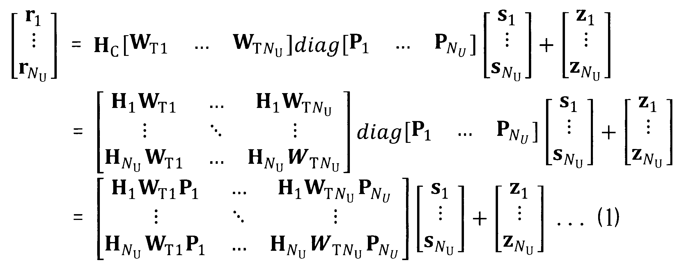
1(4)-1. ブロック対角化による受信信号の分離
第i番目のユーザ装置UE-iにおけるNR行1列の受信信号ベクトルを
以上の式(1)中の行列

の非対角成分、すなわち

は、第iユーザへの信号が、第iユーザ以外の第kユーザへの信号に対して与える干渉成分に相当する。そのため、プリコーディング制御部70は、

を充足する各プリコーディング行列

を設定することにより、以上の行列(2)の非対角成分(干渉成分)を全て

にすること(すなわち、行列(2)をブロック対角化すること)が可能である。
行列(2)をブロック対角化した後の式(1)は、以下の式で表される。

以上の式(3)に基づくと、第iユーザの受信信号ベクトルは

と表される。すなわち、プリコーディング制御部70が、行列(2)をブロック対角化する各プリコーディング行列

を設定することにより、第i番目のユーザ装置UE-iについて、当該ユーザ装置UE-iに対応する送信BFウェイト行列

を選択し、かつ当該ユーザ装置UE-iに対応するチャネル行列

以外のチャネル行列

の影響(チャネル応答)をゼロにすることができる(すなわち、MU-MIMO対象の複数ユーザを直交化することができる)。結果として、第iユーザについて、干渉信号成分を含まない受信信号ベクトルを得ることができる。
1(4)-2. ブロック対角化を実現するプリコーディング行列の算定
以下、プリコーディング制御部70が、前述の行列(2)
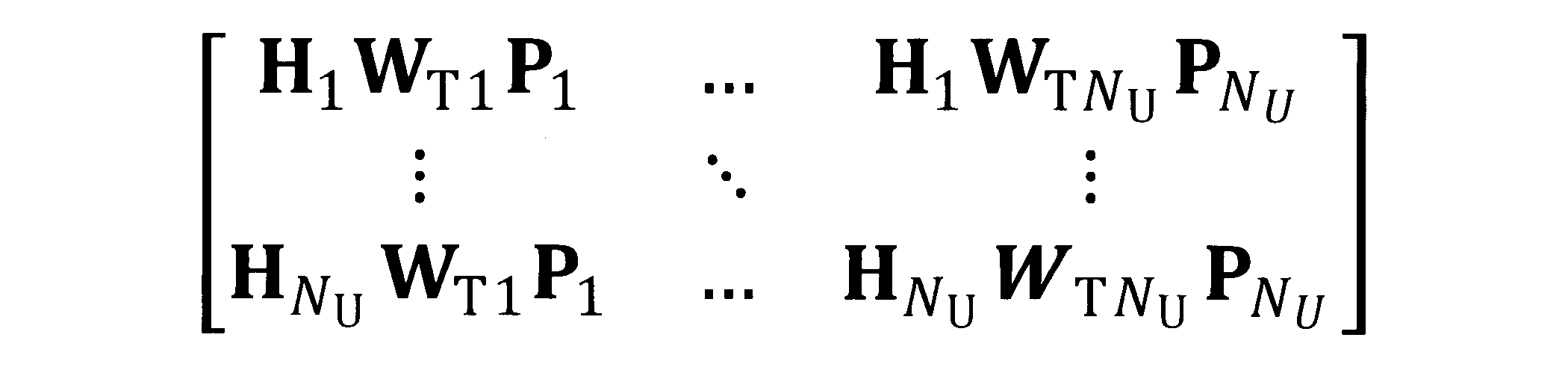
をブロック対角化するNU個のプリコーディング行列

を求める。以下、

と表記することにより、送信BFウェイト行列とチャネル行列とを一体として扱う。なお、以下において、行列

を「等価チャネル行列」と称する場合がある。
以下、プリコーディング制御部70が、前述の行列(2)
第iユーザに対応する送信BFウェイト行列を含む等価チャネル行列

のうち、第iユーザに対応するチャネル行列を含む等価チャネル行列

を除外した、NR・(NU-1)行LTi列の等価チャネル行列のセット(除外チャネル行列)を、以下のように定義する。

以上の除外チャネル行列は、第iユーザに対応する送信BFウェイト行列

に対して、第iユーザ以外のユーザに対応するチャネル行列

をそれぞれ乗算して得られる、複数の等価チャネル行列を含むセットと表現することもできる。
以上の除外チャネル行列に対する特異値分解により、以下の式(4)が得られる。

なお、(・)Hは共役転置行列を示す。
以上の式(4)において、左特異行列

は、NR・(NU-1)行NR・(NU-1)列のユニタリ行列である。右特異行列

は、LTi行LTi列のユニタリ行列である。特異値行列

は、

の特異値を対角成分として有し、非対角成分として0を有するNR・(NU-1)行LTi列の行列である。また、

は、LTi行NR列の行列であり、

は、LTi行(LTi-NR)列の行列である。


ここで、第1固有ベクトル

は、以下の式(5)を満たす。
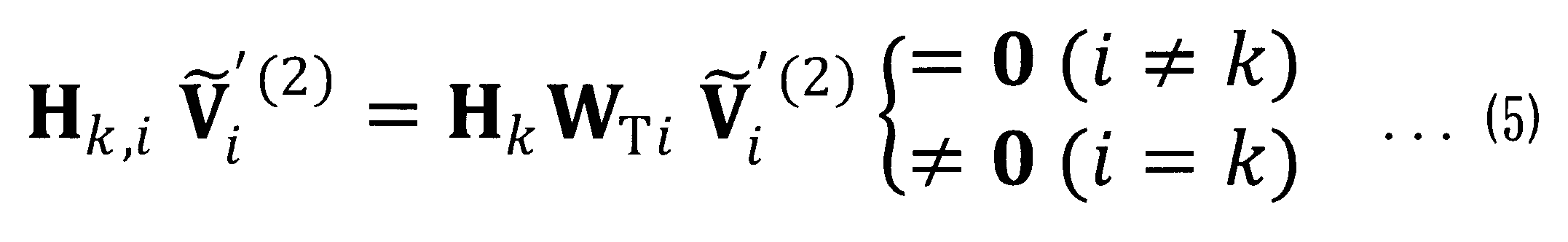
次いで、等価チャネル行列と第1固有ベクトルとの積

に対する特異値分解により、以下の式(6)が得られる。

以上の式(5)において、左特異行列

は、NR行NR列のユニタリ行列である。右特異行列

は、(LTi-NR)行(LTi-NR)列のユニタリ行列である。特異値行列

は、

の特異値を対角成分として有し、非対角成分として0を有するNR行(LTi-NR)列の行列である。また、

は、(LTi-NR)行NR列の行列であり、

は、(LTi-NR)行(LTi-NR-NR)列の行列である。


以上のようにして得られた固有ベクトル(第1固有ベクトルおよび第2固有ベクトル)に基づいて、以下の式(7)のように第iユーザのプリコーディング行列が求められる。

また、第iユーザのポストコーディング行列は以下の式(8)のように求められる。

前述した行列(2)の非対角成分

に以上の式(7)を代入すると、

が得られる。以上の非対角成分は、式(5)の関係に基づき

となる。
以上のように、プリコーディング制御部70が、式(7)のように各ユーザのプリコーディング行列を設定することにより、行列(2)がブロック対角化され、式(3)が成立する(すなわち、MU-MIMO対象の複数ユーザが互いに直交化される)。
式(8)のポストコーディング行列を用いると、式(3)は更に以下のように変形できる。

なお、以上のブロック対角化が成立するには、各ユーザ(第iユーザ)が使用する送信ビーム数LTiがシステム全体の受信アンテナAR数NR・NU以上である必要がある(LTi≧NR・NU)。また、前述のように、第iユーザの送信ビーム数がLTi=LT/NUで表される場合には、システム全体の送信ビーム数LTはNR・NU
2以上である必要がある(LT≧NR・NU
2)。
1(4)-3. ウェイト行列の決定
以上のように、プリコーディング制御部70が、NU個のプリコーディング行列

を決定することにより、MU-MIMOシステムにおける全体チャネル行列

のブロック対角化が実現される。換言すると、プリコーディング行列

が前述のように決定される限りにおいて、送信BFウェイト行列

および受信BFウェイト行列

は任意に決定され得る。
以上のように、プリコーディング制御部70が、NU個のプリコーディング行列
本実施形態において、送信BFウェイト制御部80は、第iユーザの送信BFウェイト行列

を、例えば、フィードバック情報に基づいて第iユーザにおける受信電力を最大化させる値に決定してもよいし、第iユーザの信号対干渉比(Signal-to-Interference Ratio)を最大化させる値に決定してもよいし、システム全体のチャネル容量(キャパシティ)を最大化させる値に決定してもよい。上述したようにフィードバック情報には、受信電力が所望電力であるか干渉電力であるかを示す判定情報が含まれているので、送信BFウェイト制御部80は、受信電力が所望電力であるか干渉電力であるかを判断する必要がなくなる。よって、送信BFウェイト制御部80の処理負荷を軽減することが可能となる。
送信BFウェイト制御部80は、第iユーザの送信BFウェイト行列

を、可変移相器PSおよび振幅調整器AAが施した処理によって生じた位相および振幅の変化を示すステアリングベクトルを用いて生成してもよいし、DFT(Discrete Fourier Transform)プリコーディングに基づいて生成してもよいし、バトラーマトリックスを用いて、複数ユーザ間が互いに直交化された送信ビームを生成してもよい。
また、本実施形態において、第iユーザの受信BFウェイト行列

は、NR行NR列の単位行列として決定される。すなわち、受信側ではBFウェイトが掛からない構成が採用される。
1(4)-3-1. 送信BFウェイト行列の決定の具体例
第iユーザについて、ステアリングベクトルを用いて送信BFウェイト行列を決定する構成を、以下に具体的に例示する。前述の通り、送信BFウェイト行列は

と表現される。第l番目の送信ビームに対応する送信BFウェイトベクトル

の候補は、候補により異なる変数であるΦ(水平角度)およびθ(垂直角度)を有する以下のステアリングベクトル
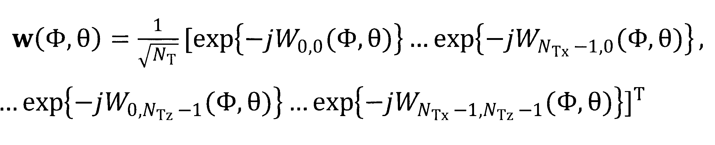
によって表現される。ここで、式中の

は、複数の送信アンテナATが配置された一様平面アレーの横nx番目(nx=0~NTx-1)、縦nz番目(nz=0~NTz-1)のアンテナ素子における位相回転量であり、

と表現される。λは、搬送波の波長を示す。
第iユーザについて、ステアリングベクトルを用いて送信BFウェイト行列を決定する構成を、以下に具体的に例示する。前述の通り、送信BFウェイト行列は
図11は、送信BFウェイト行列の決定処理の動作フローである。スモール基地局MMNBが、第l番目の送信ビームに対応する送信BFウェイトベクトル

の候補(すなわち、ステアリングベクトルの変数であるΦおよびθの組合せ)を選択し(S10)、相互に直交するLTi個のストリームの参照信号を送信する(S20)。この処理により、一つの候補ビームがスモール基地局MMNBからユーザ装置UEに送信される。候補ビームを受信したユーザ装置UEは、測定部180を用いて送信された参照信号の受信電力を測定する(S30)。
この後、ユーザ装置UEは、フィードバック処理を実行する(S40:YES)。図12はフィードバック処理の内容を示すフローチャートである。まず、比較部190は受信電力が第1閾値REF1以上であるか否かを判定する(S41)。受信電力が第1閾値REF1未満である場合、判定条件は否定され(S41:NO)、フィードバック部200は、フェードバック情報をスモール基地局MMNBにフィードバックせずに処理を終了する(S42)。
一方、受信電力が第1閾値REF1以上である場合、比較部190は受信電力が第2閾値REF2以上であるか否かを判定する(S42)。受信電力が第2閾値REF2未満である場合、判定条件は否定され(S42:NO)、フィードバック部200は、受信電力が干渉電力であるとしてスモール基地局MMNBにフィードバックする(S44)。一方、受信電力が第2閾値REF2以上である場合、判定条件は肯定され(S43:YES)、フィードバック部200は、受信電力が所望電力であるとしてスモール基地局MMNBにフィードバックする(S45)。
図13は、ある候補ビームを送信した場合の受信電力のフィードバックについて具体例を示す説明図である。この例では、スモール基地局MMNBのMMセルCmmに、ユーザ装置UE-1、UE-2、およびUE-3が含まれるものとする。スモール基地局MMNBから所定方向の候補ビームが送信されると、ユーザ装置UE-1~UE-3の各々において受信電力の測定が行われる。ここで、ユーザ装置UE-1において測定された受信電力がW1、ユーザ装置UE-2において測定された受信電力がW2、ユーザ装置UE-3において測定された受信電力がW3であったとする。この例では、W1<REF1<W2<REF2<W3の関係がある。
この場合、ユーザ装置UE-1において測定された受信電力W1は第1閾値REF1未満であるので、ユーザ装置UE-1からはフィードバック情報がスモール基地局MMNBにフィードバックされない。また、ユーザ装置UE-2において測定された受信電力W2は第1閾値REF1以上第2閾値REF2未満であるので、ユーザ装置UE-2からは受信電力W2が干渉電力としてスモール基地局MMNBにフィードバックされる。さらに、ユーザ装置UE-3において測定された受信電力W3は第2閾値REF2以上であるので、ユーザ装置UE-3からは受信電力W3が所望電力としてスモール基地局MMNBにフィードバックされる。
上述したように第1閾値REF1は、受信電力が通信に与える影響を無視できる干渉電力であるか否かを判定できる値に定められている。したがって、受信電力が第1閾値REF1未満の場合にフィードバック情報をスモール基地局MMNBに送信しなくても、BFウェイトを決定する際に問題とならない。MU-MIMOでは、複数のユーザ装置UEからスモール基地局MMNBへフィードバックが必要となる。しかし、フィードバック情報を送信しないことによってフィードバック情報量を削減することができる。
説明を図11に戻す。スモール基地局MMNBは、全てのステアリングベクトルの候補の選択が終了するまで、以上のステップを繰り返す(S50:NO)。送信BFウェイトベクトルの候補(すなわち、Φおよびθの組合せ)は、所定の差分値ΔΦおよびΔθを単位として偏移しながら選択されると好適である。この処理により、図14に示すように、水平方向および垂直方向に偏移した複数の候補ビームが、ユーザ装置UE-1~UE-NUに送信される。
そして、全てのステアリングベクトルの候補の選択が終了すると(S50:YES)、スモール基地局MMNBは、ユーザ装置UEから送信されてフィードバックされた送信BFウェイトベクトルの候補の各々に対応する参照信号の受信電力に基づいて、第l番目の送信ビームに対応する最適な送信BFウェイトベクトル

の候補(すなわち、Φおよびθの組合せ)を一定の基準に従って決定する(S60)。例えば、システム全体のキャパシティを最大とする、あるいは、特定のユーザ装置UEのスループットを高めるなどの基準を採用してもよい。
以上の動作が第iユーザの送信ビーム数であるLTi回にわたって繰り返されることにより(S70:NO)、第iユーザの送信BFウェイト行列

が決定される。
1(5). プリコーディング行列およびポストコーディング行列の決定処理の動作フロー
図15は、本実施形態のプリコーディング行列およびポストコーディング行列の決定処理を示す動作フローである。なお、以下の動作フローにおいて、各ユーザの送信BFウェイト行列

および受信BFウェイト行列

は、例えば前述の手法(「1(3)-3. ウェイト行列の決定」に記載の手法)により、予め決定されているものとする。前述の通り、本実施形態の受信BFウェイト行列

は単位行列である。
図15は、本実施形態のプリコーディング行列およびポストコーディング行列の決定処理を示す動作フローである。なお、以下の動作フローにおいて、各ユーザの送信BFウェイト行列
スモール基地局MMNBの送信BFウェイト制御部80は、送信ビームフォーミング部54に、参照信号RSに対して、全ユーザの送信BFウェイト行列

を用いたアナログ送信ビームフォーミングを実行させ、NT本の送信アンテナATから送信させる(S100)。
送信アンテナATから送信された参照信号RSは、各々のユーザ装置UE(UE-1,…,UE-NU)に向かう空間(伝搬路)を伝搬することにより、各々のユーザ装置UEに対応するチャネル行列

が乗算された参照信号RSとなって、各々のユーザ装置UE(UE-1,…,UE-NU)に到達する。
第i番目のユーザ装置UE-iの受信BFウェイト制御部160は、受信ビームフォーミング部112に、受信アンテナARに受信された参照信号RSに対して、単位行列である受信BFウェイト行列

を用いてアナログ受信ビームフォーミングを実行させる(すなわち、受信ウェイトを掛けない)。
受信ビームフォーミング部112に受信された参照信号RSは、ダウンコンバート部114とAD変換部120とを経て送受信特性推定部150に入力される。送受信特性推定部150は、入力された参照信号RSを用いて、等価チャネル行列
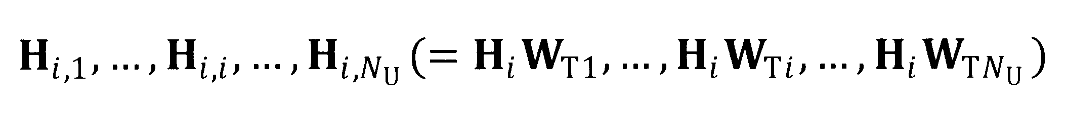
を推定する(S200)。以上の等価チャネル行列は、送信ビームフォーミングおよび空間伝搬による信号の変化を示す特性行列である。以上の等価チャネル行列の推定は、一般的なチャネル推定と同様に実行される。例えば、最小二乗法を用いた推定が可能である。推定された等価チャネル行列は、フィードバック部200を介して第iユーザ装置UE-iからフィードバックされ(S300)、スモール基地局MMNBに受信される。
ここで、第iユーザのチャネル行列のサイズは、NT×NRである。これに対し、第iユーザの等価チャネル行列のサイズはLTi×NRであるため、チャネル行列をフィードバックするよりもフィードバック情報の情報量を削減することができる。この結果、フィードバック情報の送信に伴うオーバヘッドを削減し、データ伝送のスループットを向上させることができる。
ここで、第iユーザのチャネル行列のサイズは、NT×NRである。これに対し、第iユーザの等価チャネル行列のサイズはLTi×NRであるため、チャネル行列をフィードバックするよりもフィードバック情報の情報量を削減することができる。この結果、フィードバック情報の送信に伴うオーバヘッドを削減し、データ伝送のスループットを向上させることができる。
全てのユーザ装置UE(UE-1,…,UE-NU)が以上のステップS200およびS300を実行する結果として、スモール基地局MMNBが、等価チャネル行列の全ての組合せ

を取得する。
スモール基地局MMNBのプリコーディング制御部70は、取得した等価チャネル行列の全ての組合せを用いて、全ユーザの除外チャネル行列

を生成し、前述の手法(「1(3)-2. ブロック対角化を実現するプリコーディング行列の算定」にて説明される手法)に従って、NU個のプリコーディング行列

およびポストコーディング行列

を決定する(S400)。
なお、本例においては、プリコーディング行列およびポストコーディング行列の決定が、スモール基地局MMNB(プリコーディング制御部70)にて実行される。決定されたポストコーディング行列は、それぞれ、フィードバック部60を介して、対応するユーザ装置UEに通知される。
以上の本実施形態の構成によれば、固定ビームフォーミングが採用されるMU-MIMO環境において、第iユーザの送信BFウェイト行列

に第iユーザ以外のユーザのチャネル行列

をそれぞれ乗算した等価チャネル行列

のセットである除外チャネル行列
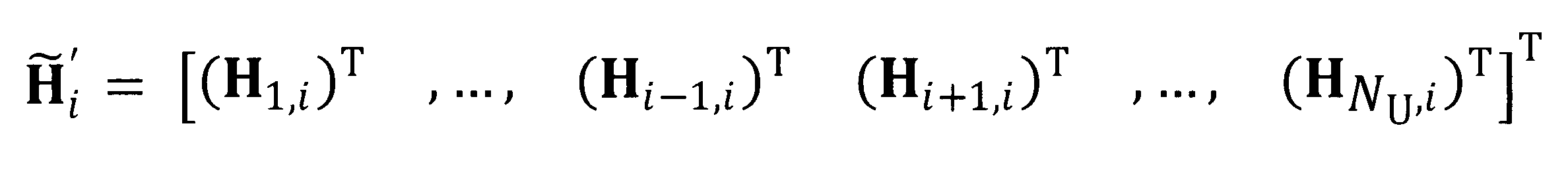
に基づいて決定されたプリコーディング行列

を用いることにより、全ユーザ(UE-1,…,UE-NU)に対する等価チャネル行列を成分とする行列

がブロック対角化される(干渉成分に相当する非対角成分が0になる)。結果として、MU-MIMO対象ユーザ間の干渉制御が実現される。
また、各ユーザ装置UEが受信電力をフィードバックするか否かを判断したので、スモール基地局へ送信するフィードバック情報の情報量を削減することができる。しかも、フィードバック情報には受信電力が干渉電力であるか所望電力であるかを示す判定情報が含まれているので、スモール基地局MMNBでは、送信BFウェイトを決定するための処理負荷を軽減することが可能となる。
また、各ユーザ装置UEが受信電力をフィードバックするか否かを判断したので、スモール基地局へ送信するフィードバック情報の情報量を削減することができる。しかも、フィードバック情報には受信電力が干渉電力であるか所望電力であるかを示す判定情報が含まれているので、スモール基地局MMNBでは、送信BFウェイトを決定するための処理負荷を軽減することが可能となる。
2. 変形例
以上の実施形態は多様に変形される。具体的な変形の態様を以下に例示する。以上の実施の形態および以下の例示から任意に選択された2以上の態様は、相互に矛盾しない限り適宜に併合され得る。
以上の実施形態は多様に変形される。具体的な変形の態様を以下に例示する。以上の実施の形態および以下の例示から任意に選択された2以上の態様は、相互に矛盾しない限り適宜に併合され得る。
2(1). 変形例1
以上の実施形態においては、受信電力をユーザ装置UEからスモール基地局MMNBへフィードバックした。しかし、本発明はこれに限定されない。例えば、フィードバックする情報は受信電力の値に限らない。例えば、ユーザ装置UEにおいて受信電力を量子化し、そのインデックスのみをフィードバックすることでフィードバック情報の情報量を削減してもよい。具体的には、受信電力を量子化して得た量子化受信電力を示す量子化受信電力情報と、受信電力が干渉電力であるか所望電力であるかを示す判定情報を含むフィードバック情報をユーザ装置UEが生成し、これをユーザ装置UEがスモール基地局MMNBへフィードバックしてもよい。
以上の実施形態においては、受信電力をユーザ装置UEからスモール基地局MMNBへフィードバックした。しかし、本発明はこれに限定されない。例えば、フィードバックする情報は受信電力の値に限らない。例えば、ユーザ装置UEにおいて受信電力を量子化し、そのインデックスのみをフィードバックすることでフィードバック情報の情報量を削減してもよい。具体的には、受信電力を量子化して得た量子化受信電力を示す量子化受信電力情報と、受信電力が干渉電力であるか所望電力であるかを示す判定情報を含むフィードバック情報をユーザ装置UEが生成し、これをユーザ装置UEがスモール基地局MMNBへフィードバックしてもよい。
具体的には、図16に示すように、第1閾値REF1以上の受信電力を9段階で量子化してもよい。フィードバックする否かを判定するための第1閾値REF1との比較の対象となるのは、受信電力であってもよいし、あるいは量子化受信電力であってもよい。また、受信電力が所望電力であるか干渉電力であるかを判定するための第2閾値REF2との比較の対象となるのは、受信電力であってもよいし、あるいは量子化受信電力であってもよい。
同図に示す例では、受信電力がW3の場合、量子化受信電力は「7」となる。量子化受信電力「7」は第2閾値REF2以上であるので、所望電力として量子化受信電力「7」がフィードバックされる。
この変形例によれば、フィードバック情報の情報量が削減され、システム全体のオーバヘッドを低減することができる。
同図に示す例では、受信電力がW3の場合、量子化受信電力は「7」となる。量子化受信電力「7」は第2閾値REF2以上であるので、所望電力として量子化受信電力「7」がフィードバックされる。
この変形例によれば、フィードバック情報の情報量が削減され、システム全体のオーバヘッドを低減することができる。
2(2). 変形例2
上述した実施形態では、ユーザ装置UEは無線通信が確立している一つのスモール基地局MMNBとの間の通信において干渉電力を問題とした。このほかに、ユーザ装置UEは他のスモール基地局MMNBからの送信ビームによって干渉を受ける場合がある。
そこで、ユーザ装置UEは、以下のようにフィードバック情報を生成し、無線通信が確立しているスモール基地局MMNBへフィードバックしてもよい。なお、以下の説明では、無線通信が確立しているスモール基地局MMNBを第1スモール基地局MMNB1と称し、他のスモール基地局MMNBを第2スモール基地局MMNB2と称する。例えば、図17に示すように第1スモール基地局MMNB1のセルCmm1と第2スモール基地局MMNB2のセルCmm2との境界付近にユーザ装置UE-3が位置しているとする。この場合、ユーザ装置UE-3は、第1スモール基地局MMNB1から所望ビームB1を受信する一方、第2スモール基地局MMNB2から干渉ビームB2を受信する。
まず、第1スモール基地局MMNB1が複数の候補ビームを送信してビームサーチを実行する前に、測定部180は、第2スモール基地局MMNB2から送信される送信ビーム(この例では、干渉ビームB2)について、他セル干渉電力を測定する。
次に、比較部190は、第3閾値REF3と他セル干渉電力とを比較し、比較結果をフィードバック部200に出力する。フィードバック部200は、他セル干渉電力が第3閾値REF3以上である場合に、第2スモール基地局MMNB2からの干渉があることを示す他セル干渉情報を含むフィードバック情報を第1スモール基地局MMNB1に送信する。一方、他セル干渉電力が第3閾値REF3未満である場合、フィードバック部200はフィードバック情報を第1スモール基地局MMNB1に送信しない。フィードバック情報を第1スモール基地局MMNB1に送信しない場合のユーザ装置UEの動作は、上述した実施形態と同様である。すなわち、ユーザ装置UEは、第1スモール基地局MMNB1から複数の候補ビームが送信されると、受信電力に基づいてフィードバック情報を送信するか否かを判定し、フィードバックする場合には、受信電力が干渉電力であるか所望電力であるかを示す判定情報を含むフィードバック情報を送信する。
ここで、他セル干渉情報は、第2スモール基地局MMNB2を識別するための情報と、干渉の原因となる第2スモール基地局MMNB2からの送信ビーム(この例では、干渉ビームB2)を識別するための情報とを含むことが好ましい。さらに、フィードバック情報は、他セル干渉電力を示す他セル干渉電力情報を含むことが好ましい。
このフィードバック情報を受信した第1スモール基地局MMNB1は、第2スモール基地局MMNB2と協調してセル間干渉制御を実行することが好ましい。第3閾値REF3は、第2スモール基地局MMNB2からの送信ビームを通信品質に与える影響を無視できるか否かを判定できる値に設定されており、記憶部210に記憶されている。なお、第3閾値REF3は、上述した第1閾値REF1および第2閾値REF2と無関係に設定されてもよい。例えば、第3閾値REF3は、第1閾値REF1以上に設定されてもよい。
また、ユーザ装置UEの他の態様として、まず、第1スモール基地局MMNB1が複数の候補ビームを送信してビームサーチを実行する前に、測定部180が、第2スモール基地局MMNB2から送信される送信ビームについて、他セル干渉電力を測定する構成としてもよい。
次に、比較部190は、第3閾値REF3と他セル干渉電力とを比較し、比較結果をフィードバック部200に出力する。フィードバック部200は、他セル干渉電力が第3閾値REF3以上である場合に、第1スモール基地局MMNB1から複数の候補ビームについて第1スモール基地局MMNB1へフィードバックする際に、フィードバック情報を変更する。具体的には、フィードバック部200は、受信電力情報の替わりに、受信電力を他セル干渉電力に応じて補正した補正受信電力に関する補正受信電力情報を含むフィードバック情報を生成し、第1スモール基地局MMNB1へ送信する。ここで、補正受信電力情報は補正受信電力そのものであってもよいし、補正受信電力を量子化した情報であってもよい。
所望電力としてフィードバックする受信電力は、他セル干渉電力が大きくなるほど、小さい電力に補正されることが好ましい。このように補正することによって、第1スモール基地局MMNB1では、送信BFウェイトが調整され、無線品質が維持される。この処理によって、他セル干渉電力があっても当該ユーザ装置UEに対する所望ビームの利得を大きくすることが可能となる。
所望電力としてフィードバックする受信電力は、他セル干渉電力が大きくなるほど、小さい電力に補正されることが好ましい。このように補正することによって、第1スモール基地局MMNB1では、送信BFウェイトが調整され、無線品質が維持される。この処理によって、他セル干渉電力があっても当該ユーザ装置UEに対する所望ビームの利得を大きくすることが可能となる。
2(3). 変形例3
上述した実施形態において、第1閾値REF1および第2閾値REF2は記憶部210に記憶された。しかし、これらは、ユーザ装置UEごとに任意に設定されてもよい。また、この設定は、スモール基地局MMNBからの指定で設定してもよいし、あるいは、ユーザ装置UEにおいて独自に設定してもよい。
図18に受信電力と確率密度との関係の一例を示す。ここで、第2閾値REF2を下げれば、複数の候補ビームのうち所望ビームとしてフィードバックするビーム数が増加する。このため、BF利得を大きくすることができる。一方、第2閾値REF2を上げれば複数の候補ビームのうち干渉ビームとしてフィードバックするビーム数が増加する。このため、スモール基地局MMNBにおける干渉制御を強化することができる。
ここで、ユーザ装置UEは、所望電力に関するフィードバック情報の対象となる候補ビームの数が所望の通信速度に応じた数以上となる値に、第2閾値REF2を設定する設定部を備えてもよい。この構成により、ユーザ装置UEは、所望の通信速度に応じてBF利得を制御することができる。スモール基地局MMNBにおける処理負荷を軽減することができる。
また、ユーザ装置UEは、平均的な受信電力に応じて、第1閾値REF1および第2閾値REF2の少なくとも一方を設定する設定部を備えてもよい。
さらに、ユーザ装置UEは、受信電力の分布に応じて、干渉を制御するために第1閾値REF1および第2閾値REF2の少なくとも一方を設定する設定部を備えてもよい。
また、ユーザ装置UEは、平均的な受信電力に応じて、第1閾値REF1および第2閾値REF2の少なくとも一方を設定する設定部を備えてもよい。
さらに、ユーザ装置UEは、受信電力の分布に応じて、干渉を制御するために第1閾値REF1および第2閾値REF2の少なくとも一方を設定する設定部を備えてもよい。
2(4). 変形例4
上述した実施形態では、送受信特性推定部150は、入力された参照信号RSを用いて、等価チャネル行列を推定する。しかしながら、本発明はこれに限定されない。例えば、等価チャネル行列の代わりにチャネル行列を推定した後、送信BFウェイト行列を決定してもよい。この場合、推定したチャネル行列はユーザ装置UEからスモール基地局MMNBにフィードバックされる。この際、ユーザ装置UEは、チャネル行列の要素を量子化してフィードバックしてもよい。また、上述した実施形態では、ユーザ装置UEは、等価チャネル行列の要素をフィードバックする。この際、等価チャネル行列の要素を量子化してフィードバックしてもよい。チャネル行列又は等価チャネル行列の量子化により、フィードバック情報の情報量を削減することができる。
上述した実施形態では、送受信特性推定部150は、入力された参照信号RSを用いて、等価チャネル行列を推定する。しかしながら、本発明はこれに限定されない。例えば、等価チャネル行列の代わりにチャネル行列を推定した後、送信BFウェイト行列を決定してもよい。この場合、推定したチャネル行列はユーザ装置UEからスモール基地局MMNBにフィードバックされる。この際、ユーザ装置UEは、チャネル行列の要素を量子化してフィードバックしてもよい。また、上述した実施形態では、ユーザ装置UEは、等価チャネル行列の要素をフィードバックする。この際、等価チャネル行列の要素を量子化してフィードバックしてもよい。チャネル行列又は等価チャネル行列の量子化により、フィードバック情報の情報量を削減することができる。
2(5). 変形例5
上述した実施形態では、ある1つのユーザ(第iユーザ)の送信ビーム数LTiは固定的に設定される(例えば、LTi=LT/NU)。しかしながら、送信ビーム数LTiが動的に設定されてもよい。例えば、送信ビーム数LTiは、第iユーザの通信速度を一定値以上にする数に設定されてもよいし、システム全体の通信速度をより向上させる数(好適には、通信速度を最大化する数)に設定されてもよい。また、送信ビーム数LTiは、送信ビーム数LTiが固定的に設定される場合と比較して通信速度をより向上させる数に設定されてもよいし、第iユーザのキャパシティをより大きくする数(好適には、キャパシティを最大化する数)に設定されてもよい。例えば、MCS(Modulation and Coding Scheme)の値に応じて送信ビーム数LTiが設定されると好適である。
上述した実施形態では、ある1つのユーザ(第iユーザ)の送信ビーム数LTiは固定的に設定される(例えば、LTi=LT/NU)。しかしながら、送信ビーム数LTiが動的に設定されてもよい。例えば、送信ビーム数LTiは、第iユーザの通信速度を一定値以上にする数に設定されてもよいし、システム全体の通信速度をより向上させる数(好適には、通信速度を最大化する数)に設定されてもよい。また、送信ビーム数LTiは、送信ビーム数LTiが固定的に設定される場合と比較して通信速度をより向上させる数に設定されてもよいし、第iユーザのキャパシティをより大きくする数(好適には、キャパシティを最大化する数)に設定されてもよい。例えば、MCS(Modulation and Coding Scheme)の値に応じて送信ビーム数LTiが設定されると好適である。
以上の構成によれば、ユーザごとに要求される品質の差異に対して柔軟に対応することが可能である。また、システム全体の通信速度の向上を図ると共に、ユーザ間の通信速度の公平性を確保することが可能である。
2(6). 変形例6
以上の実施形態において、スモール基地局MMNBとユーザ装置UEとの制御情報の通信は、任意のルートにて実行され得る。例えば、スモール基地局MMNBとユーザ装置UEとの間に無線リンクが確立されている場合には、無線信号を直接的に送受信することで制御情報を交換してもよい。また、以上の無線リンクが確立されていない場合には、マクロ基地局MeNB経由でスモール基地局MMNBとユーザ装置UEとが制御情報を送受信してもよい。
以上の実施形態において、スモール基地局MMNBとユーザ装置UEとの制御情報の通信は、任意のルートにて実行され得る。例えば、スモール基地局MMNBとユーザ装置UEとの間に無線リンクが確立されている場合には、無線信号を直接的に送受信することで制御情報を交換してもよい。また、以上の無線リンクが確立されていない場合には、マクロ基地局MeNB経由でスモール基地局MMNBとユーザ装置UEとが制御情報を送受信してもよい。
2(7). 変形例7
スモール基地局MMNBの送信ビームフォーミング部54は、NT本の送信アンテナATを全て用いて1つの送信ビームが生成されるフルアレー型構成であってもよいし、(NT/LT)本の送信アンテナATを用いて1つの送信ビームが生成されるサブアレー型構成であってもよい。いずれの構成によっても、以上の実施形態のユーザ多重が実現される。
スモール基地局MMNBの送信ビームフォーミング部54は、NT本の送信アンテナATを全て用いて1つの送信ビームが生成されるフルアレー型構成であってもよいし、(NT/LT)本の送信アンテナATを用いて1つの送信ビームが生成されるサブアレー型構成であってもよい。いずれの構成によっても、以上の実施形態のユーザ多重が実現される。
2(8). 変形例8
ユーザ装置UEは、ネットワーク内の基地局(マクロ基地局MeNBおよび/またはスモール基地局MMNB)と無線通信が可能な任意の装置である。ユーザ装置UEは、例えば、フィーチャーフォンまたはスマートフォン等の携帯電話端末でもよく、タブレット端末でもよく、デスクトップ型パーソナルコンピュータでもよく、ノート型パーソナルコンピュータでもよく、UMPC(Ultra-Mobile Personal Computer)でもよく、携帯用ゲーム機でもよく、その他の無線端末でもよい。
また、ユーザ装置UEはスモール基地局MMNBとの無線通信だけでなく、単なる基地局との間の無線通信に上述した通信を適用してもよいことは勿論である。
2(9). 変形例9
無線通信システム1内の各要素(ユーザ装置UEおよびスモール基地局MMNB)においてCPUが実行する各機能は、CPUの代わりに、ハードウェアが実行してもよいし、例えばFPGA(Field Programmable Gate Array)、またはDSP(Digital Signal Processor)等のプログラマブルロジックデバイスが実行してもよい。
無線通信システム1内の各要素(ユーザ装置UEおよびスモール基地局MMNB)においてCPUが実行する各機能は、CPUの代わりに、ハードウェアが実行してもよいし、例えばFPGA(Field Programmable Gate Array)、またはDSP(Digital Signal Processor)等のプログラマブルロジックデバイスが実行してもよい。
1……無線通信システム、MMNB……スモール基地局、10……データ信号生成部、20……参照信号生成部、30……ベースバンド処理部、32……プリコーディング部、40……変換部、50……処理部、52……アップコンバート部、54……送信ビームフォーミング部、60,200……フィードバック部、70……プリコーディング制御部、80……ウェイト制御部、90……記憶部、UE……ユーザ装置、110……処理部、112……受信ビームフォーミング部、114……ダウンコンバート部、120……変換部、130……ベースバンド処理部、132……ポストコーディング部、140……信号解析部、150……送受信特性推定部、160……ウェイト制御部、170……ポストコーディング制御部、180……測定部、190……比較部、200……フィードバック部、210……記憶部、AA……振幅調整器、ACR……アナログ信号処理回路、ACT……アナログ信号処理回路、AD……加算器、AR……受信アンテナ、AT……送信アンテナ、Cm……マクロセル、Cmm……Massive-MIMOセル、DCR……ディジタル信号処理回路、DCT……ディジタル信号処理回路、MME……中央制御局、MP……乗算器、MeNB……マクロ基地局、PCR……処理回路、PCT……処理回路、PS……可変移相器。
Claims (9)
- MU-MIMO通信方式を用いて無線通信を実行する基地局から送信され、送信ビームフォーミングのための複数の候補ビームを受信するユーザ装置であって、
前記複数の候補ビームの各々について、通信品質に関する指標を測定する測定部と、
第1閾値および当該第1閾値よりも大きい第2閾値の各々と前記指標とを比較する比較部と、
前記比較部の比較結果に基づいて、前記指標が前記第1閾値以上前記第2閾値未満の場合には前記指標を干渉ビームに関するフィードバック情報として前記基地局に送信し、前記指標が前記第2閾値以上の場合には前記指標を所望ビームに関するフィードバック情報として前記基地局に送信し、前記指標が前記第1閾値未満の場合にはフィードバック情報を前記基地局に送信しないフィードバック部と、
を備えるユーザ装置。 - 前記通信品質に関する指標は受信電力であり、
前記測定部は、前記複数の候補ビームの各々について、受信電力を測定し、
前記比較部は、前記第1閾値および前記第2閾値の各々と前記受信電力とを比較し、
前記フィードバック部は、前記比較部の比較結果に基づいて、前記受信電力が前記第1閾値以上前記第2閾値未満の場合には前記受信電力を干渉電力に関するフィードバック情報として前記基地局に送信し、前記受信電力が前記第2閾値以上の場合には前記受信電力を所望電力に関するフィードバック情報として前記基地局に送信し、前記受信電力が前記第1閾値未満の場合にはフィードバック情報を前記基地局に送信しない、
請求項1に記載のユーザ装置。 - 前記フィードバック部は、前記受信電力が干渉電力であるか所望電力であるかを示す判定情報と、前記受信電力を示す受信電力情報とを含む、前記フィードバック情報を生成する請求項2に記載のユーザ装置。
- 前記フィードバック部は、前記受信電力が干渉電力であるか所望電力であるかを示す判定情報と、前記受信電力を量子化した量子化受信電力情報とを含む、前記フィードバック情報を生成する請求項2に記載のユーザ装置。
- 前記測定部は、前記基地局が前記複数の候補ビームを送信する前に、当該基地局と異なる他の基地局から送信される送信ビームについて、他セル干渉電力を測定し、
前記比較部は、第3閾値と前記他セル干渉電力とを比較し、
前記フィードバック部は、前記他セル干渉電力が前記第3閾値以上である場合に、前記他の基地局からの干渉があることを示す他セル干渉情報を含む前記フィードバック情報を前記基地局に送信する、
請求項2乃至4のうちいずれか1項に記載のユーザ装置。 - 前記測定部は、前記基地局が前記複数の候補ビームを送信する前に、当該基地局と異なる他の基地局から送信される送信ビームについて、他セル干渉電力を測定し、
前記比較部は、第3閾値と前記他セル干渉電力とを比較し、
前記フィードバック部は、前記他セル干渉電力が前記第3閾値以上である場合には、前記受信電力情報の替わりに、前記受信電力を前記他セル干渉電力に応じて補正した補正受信電力に関する補正受信電力情報を含む前記フィードバック情報を前記基地局に送信する、
請求項2に記載のユーザ装置。 - 前記所望電力に関するフィードバック情報の対象となる候補ビームの数が所望の通信速度に応じた数以上となる値に、前記第2閾値を設定する設定部を備える請求項1乃至6のうちいずれか1項に記載のユーザ装置。
- MU-MIMO通信方式を用いて、複数のユーザ装置と無線通信を実行可能な基地局であって、
前記複数のユーザ装置の各々は、請求項1乃至6のうちいずれか1項に記載のユーザ装置であり、
前記基地局は、
M(Mは2以上の整数)本のストリームに対して、プリコーディングウェイト行列を用いてディジタルプリコーディングを施すプリコーディング部と、
前記ディジタルプリコーディングが施された後の信号に対して、送信ビームフォーミングウェイト行列に相当する位相および振幅の変化を付与するアナログ送信ビームフォーミングまたは時間領域のディジタル送信ビームフォーミングを施す送信ビームフォーミング部と、
前記送信ビームフォーミングが施された信号を送信するとともに、前記複数のユーザ装置の各々から送信された前記フィードバック情報を受信する複数のアンテナと、
前記送信ビームフォーミング部を制御する送信ビームフォーミングウェイト制御部と、
を備え、
前記送信ビームフォーミングウェイト制御部は、前記複数の候補ビームの各々に対応する送信ビームフォーミングウェイト行列を選択して、選択した送信ビームフォーミングウェイト行列に相当する位相および振幅の変化を付与する送信ビームフォーミングを、前記送信ビームフォーミング部に実行させ、前記複数のユーザ装置の各々に対応する前記フィードバック情報に基づいて、M本のストリームを送信するための送信ビームフォーミングウェイト行列を決定し、決定した送信ビームフォーミングウェイト行列に相当する位相および振幅の変化を付与する送信ビームフォーミングを、前記送信ビームフォーミング部に実行させる、
基地局。 - 前記送信ビームフォーミング部は、前記決定された送信ビームフォーミングウェイト行列に相当する位相および振幅の変化を付与する送信ビームフォーミングを参照信号に施して出力し、
前記複数のユーザ装置の各々から、前記参照信号を用いて生成された、前記送信ビームフォーミングウェイト行列に対して伝送路の伝搬特性を示すチャネル行列を乗算した等価チャネル行列を含む等価チャネル情報を受信すると、前記等価チャネル行列に基づいて
前記プリコーディングウェイト行列を得るプリコーディング制御部と、
を備える請求項8に記載の基地局。
Priority Applications (4)
| Application Number | Priority Date | Filing Date | Title |
|---|---|---|---|
| JP2017565589A JP6859586B2 (ja) | 2016-02-05 | 2017-02-01 | ユーザ装置および基地局 |
| US15/769,390 US10700756B2 (en) | 2016-02-05 | 2017-02-01 | User equipment and base station |
| EP17747461.6A EP3413486B1 (en) | 2016-02-05 | 2017-02-01 | User equipment and base station |
| CN201780005889.4A CN108476083B (zh) | 2016-02-05 | 2017-02-01 | 用户装置及基站 |
Applications Claiming Priority (2)
| Application Number | Priority Date | Filing Date | Title |
|---|---|---|---|
| JP2016021370 | 2016-02-05 | ||
| JP2016-021370 | 2016-02-05 |
Publications (1)
| Publication Number | Publication Date |
|---|---|
| WO2017135305A1 true WO2017135305A1 (ja) | 2017-08-10 |
Family
ID=59499650
Family Applications (1)
| Application Number | Title | Priority Date | Filing Date |
|---|---|---|---|
| PCT/JP2017/003605 Ceased WO2017135305A1 (ja) | 2016-02-05 | 2017-02-01 | ユーザ装置および基地局 |
Country Status (5)
| Country | Link |
|---|---|
| US (1) | US10700756B2 (ja) |
| EP (1) | EP3413486B1 (ja) |
| JP (1) | JP6859586B2 (ja) |
| CN (1) | CN108476083B (ja) |
| WO (1) | WO2017135305A1 (ja) |
Cited By (2)
| Publication number | Priority date | Publication date | Assignee | Title |
|---|---|---|---|---|
| CN108111203A (zh) * | 2017-11-17 | 2018-06-01 | 中兴通讯股份有限公司 | 一种信息反馈的方法、装置、信息接收的方法及装置 |
| JP2021016077A (ja) * | 2019-07-11 | 2021-02-12 | 富士通株式会社 | ビームフォーミング装置およびビームフォーミング方法 |
Families Citing this family (14)
| Publication number | Priority date | Publication date | Assignee | Title |
|---|---|---|---|---|
| US10892801B2 (en) * | 2016-08-12 | 2021-01-12 | Lg Electronics Inc. | Method for signaling for phase feedback, and device for same |
| WO2018038648A1 (en) * | 2016-08-22 | 2018-03-01 | Telefonaktiebolaget Lm Ericsson (Publ) | Radio node and method therein for determining precoders |
| JP7017312B2 (ja) * | 2017-02-20 | 2022-02-08 | 株式会社Nttドコモ | 無線基地局、及び、無線通信方法 |
| US10390296B2 (en) * | 2017-05-05 | 2019-08-20 | Htc Corporation | Device and method of handling a cell selection procedure or a cell reselection procedure |
| CN109548043B (zh) * | 2017-09-22 | 2020-12-11 | 中国移动通信有限公司研究院 | 小区信号质量确定、小区选择或重选方法、设备及介质 |
| DE102017131138B4 (de) * | 2017-12-22 | 2026-03-19 | Te Connectivity Germany Gmbh | Vorrichtung zum Übermitteln von Daten innerhalb eines Fahrzeugs |
| US10986661B2 (en) | 2018-09-27 | 2021-04-20 | Lenovo (Singapore) Pte. Ltd. | Transmitting a physical downlink shared channel after losing uplink synchronization |
| CN110972137B (zh) * | 2018-09-29 | 2021-09-14 | 上海华为技术有限公司 | 一种通信方法和装置 |
| US11677146B2 (en) * | 2018-12-21 | 2023-06-13 | Navid Gougol | Programmable analog beamformer |
| CN113711501A (zh) | 2019-01-11 | 2021-11-26 | 联想(新加坡)私人有限公司 | 生成信道状态信息(“csi”)报告 |
| WO2021029067A1 (ja) * | 2019-08-15 | 2021-02-18 | 株式会社Nttドコモ | 端末及び通信方法 |
| US20230164708A1 (en) * | 2020-04-05 | 2023-05-25 | Transferfi Pte. Ltd. | Channel learning and power transmission in wireless power networks |
| US11695456B2 (en) * | 2020-08-25 | 2023-07-04 | Qualcomm Incorporated | Autonomous beam configuration in radio frequency repeaters |
| CN117692955A (zh) * | 2022-08-23 | 2024-03-12 | 维沃移动通信有限公司 | 信息传输方法、装置、终端及网络侧设备 |
Citations (3)
| Publication number | Priority date | Publication date | Assignee | Title |
|---|---|---|---|---|
| JP2008228013A (ja) * | 2007-03-14 | 2008-09-25 | Kddi Corp | アンテナ制御装置、アンテナ装置および無線装置 |
| JP2013232741A (ja) | 2012-04-27 | 2013-11-14 | Ntt Docomo Inc | 無線通信方法、無線基地局及び無線通信システム |
| JP2014027368A (ja) | 2012-07-24 | 2014-02-06 | Nippon Telegr & Teleph Corp <Ntt> | 無線通信システム、および無線通信方法 |
Family Cites Families (7)
| Publication number | Priority date | Publication date | Assignee | Title |
|---|---|---|---|---|
| CN101373998B (zh) * | 2007-08-20 | 2012-07-25 | 上海贝尔阿尔卡特股份有限公司 | 低信息交互的多基站协作mimo及其调度方法和装置 |
| JP5607143B2 (ja) | 2009-04-21 | 2014-10-15 | マーベル ワールド トレード リミテッド | 通信方法、通信装置、携帯通信端末、チップセット、および、通信システム |
| JP5279677B2 (ja) | 2009-10-13 | 2013-09-04 | 株式会社日立製作所 | 無線通信システム、無線基地局装置及び無線通信方法 |
| CN103974273B (zh) * | 2013-02-06 | 2018-11-13 | 中兴通讯股份有限公司 | 干扰关系的获取方法及系统 |
| KR102043021B1 (ko) * | 2013-04-15 | 2019-11-12 | 삼성전자주식회사 | 이동 통신 시스템에서 빔포밍을 위한 스케쥴링 방법 및 장치 |
| US9912394B2 (en) * | 2014-04-09 | 2018-03-06 | Lg Electronics Inc. | Method and apparatus for performing feedback for massive antenna array based beamforming in wireless communication system |
| WO2015156495A1 (ko) * | 2014-04-09 | 2015-10-15 | 엘지전자 주식회사 | 사운딩 절차 기반의 프레임 전송 방법 및 장치 |
-
2017
- 2017-02-01 JP JP2017565589A patent/JP6859586B2/ja active Active
- 2017-02-01 WO PCT/JP2017/003605 patent/WO2017135305A1/ja not_active Ceased
- 2017-02-01 EP EP17747461.6A patent/EP3413486B1/en active Active
- 2017-02-01 US US15/769,390 patent/US10700756B2/en active Active
- 2017-02-01 CN CN201780005889.4A patent/CN108476083B/zh not_active Expired - Fee Related
Patent Citations (3)
| Publication number | Priority date | Publication date | Assignee | Title |
|---|---|---|---|---|
| JP2008228013A (ja) * | 2007-03-14 | 2008-09-25 | Kddi Corp | アンテナ制御装置、アンテナ装置および無線装置 |
| JP2013232741A (ja) | 2012-04-27 | 2013-11-14 | Ntt Docomo Inc | 無線通信方法、無線基地局及び無線通信システム |
| JP2014027368A (ja) | 2012-07-24 | 2014-02-06 | Nippon Telegr & Teleph Corp <Ntt> | 無線通信システム、および無線通信方法 |
Non-Patent Citations (3)
| Title |
|---|
| See also references of EP3413486A4 |
| TATSUKI OKUYAMA ET AL.: "Performance Evaluation of Beam Selection Schemes for Multiuser Massive MIMO using Hybrid Beamforming in High Frequency Bands", IEICE TECHNICAL REPORT, vol. 115, no. 233, 24 September 2015 (2015-09-24), pages 131 - 136, XP009507955 * |
| TATSUNORI OBARA ET AL.: "Channel Estimation for Super High Bit Rate Massive MIMO Systems Using Joint Processing of Analog Fixed Beamforming and CSI-based Precoding, Standards for Communications and Networking(CSCN", 2015 IEEE CONFERENCE, 30 October 2015 (2015-10-30), pages 300 - 304, XP032856183 * |
Cited By (5)
| Publication number | Priority date | Publication date | Assignee | Title |
|---|---|---|---|---|
| CN108111203A (zh) * | 2017-11-17 | 2018-06-01 | 中兴通讯股份有限公司 | 一种信息反馈的方法、装置、信息接收的方法及装置 |
| WO2019096230A1 (zh) * | 2017-11-17 | 2019-05-23 | 中兴通讯股份有限公司 | 信息反馈的方法、装置、信息接收的方法及装置 |
| CN108111203B (zh) * | 2017-11-17 | 2025-12-23 | 中兴通讯股份有限公司 | 一种信息反馈的方法、装置、信息接收的方法及装置 |
| JP2021016077A (ja) * | 2019-07-11 | 2021-02-12 | 富士通株式会社 | ビームフォーミング装置およびビームフォーミング方法 |
| JP7404680B2 (ja) | 2019-07-11 | 2023-12-26 | 富士通株式会社 | ビームフォーミング装置およびビームフォーミング方法 |
Also Published As
| Publication number | Publication date |
|---|---|
| EP3413486A4 (en) | 2019-01-30 |
| EP3413486B1 (en) | 2020-04-01 |
| CN108476083B (zh) | 2020-11-20 |
| JP6859586B2 (ja) | 2021-04-14 |
| JPWO2017135305A1 (ja) | 2018-11-29 |
| US10700756B2 (en) | 2020-06-30 |
| US20180331746A1 (en) | 2018-11-15 |
| CN108476083A (zh) | 2018-08-31 |
| EP3413486A1 (en) | 2018-12-12 |
Similar Documents
| Publication | Publication Date | Title |
|---|---|---|
| JP6859586B2 (ja) | ユーザ装置および基地局 | |
| JP6735439B2 (ja) | 無線通信制御方法および無線通信システム | |
| JP6666331B2 (ja) | 無線通信制御方法および無線通信システム | |
| US10951293B2 (en) | Wireless communication method and wireless communication apparatus | |
| JP6416869B2 (ja) | 無線通信制御方法および無線通信システム | |
| US9935700B2 (en) | Beam scanning method for hybrid beamforming in wireless communication system and apparatus therefor | |
| KR102438322B1 (ko) | 무선 통신 시스템들을 위한 2차원 활성 안테나 어레이 동작 | |
| EP3963845B1 (en) | Methods, distributed base station system, remote radio unit and base band unit system for handling uplink signals | |
| US11290169B2 (en) | Methods, systems and units of a distributed base station system for handling of downlink communication | |
| WO2016041492A1 (en) | Channel state information collection for wireless communication system with beamforming | |
| EP2826162B1 (en) | Node and method for generating beamformed signals for downlink communication | |
| KR20180109944A (ko) | 무선 통신 방법 및 무선 통신 디바이스 | |
| US9008008B2 (en) | Method for communicating in a MIMO context | |
| JP6029848B2 (ja) | 無線基地局 | |
| EP4701092A1 (en) | Beam forming with user fairness | |
| Villalonga | Energy-efficient digital and hybrid precoding algorithms for interference-limited cellular networks | |
| KR20230105782A (ko) | 송신 장치 및 이의 동작 방법 |
Legal Events
| Date | Code | Title | Description |
|---|---|---|---|
| 121 | Ep: the epo has been informed by wipo that ep was designated in this application |
Ref document number: 17747461 Country of ref document: EP Kind code of ref document: A1 |
|
| ENP | Entry into the national phase |
Ref document number: 2017565589 Country of ref document: JP Kind code of ref document: A |
|
| WWE | Wipo information: entry into national phase |
Ref document number: 15769390 Country of ref document: US |
|
| NENP | Non-entry into the national phase |
Ref country code: DE |