WO2017138208A1 - 内視鏡システム - Google Patents
内視鏡システム Download PDFInfo
- Publication number
- WO2017138208A1 WO2017138208A1 PCT/JP2016/083788 JP2016083788W WO2017138208A1 WO 2017138208 A1 WO2017138208 A1 WO 2017138208A1 JP 2016083788 W JP2016083788 W JP 2016083788W WO 2017138208 A1 WO2017138208 A1 WO 2017138208A1
- Authority
- WO
- WIPO (PCT)
- Prior art keywords
- endoscope
- imaging unit
- arm
- optical axis
- control device
- Prior art date
- Legal status (The legal status is an assumption and is not a legal conclusion. Google has not performed a legal analysis and makes no representation as to the accuracy of the status listed.)
- Ceased
Links
Images


Classifications
-
- A—HUMAN NECESSITIES
- A61—MEDICAL OR VETERINARY SCIENCE; HYGIENE
- A61B—DIAGNOSIS; SURGERY; IDENTIFICATION
- A61B1/00—Instruments for performing medical examinations of the interior of cavities or tubes of the body by visual or photographical inspection, e.g. endoscopes; Illuminating arrangements therefor
- A61B1/00002—Operational features of endoscopes
- A61B1/00004—Operational features of endoscopes characterised by electronic signal processing
- A61B1/00006—Operational features of endoscopes characterised by electronic signal processing of control signals
-
- A—HUMAN NECESSITIES
- A61—MEDICAL OR VETERINARY SCIENCE; HYGIENE
- A61B—DIAGNOSIS; SURGERY; IDENTIFICATION
- A61B1/00—Instruments for performing medical examinations of the interior of cavities or tubes of the body by visual or photographical inspection, e.g. endoscopes; Illuminating arrangements therefor
- A61B1/00147—Holding or positioning arrangements
- A61B1/00149—Holding or positioning arrangements using articulated arms
-
- A—HUMAN NECESSITIES
- A61—MEDICAL OR VETERINARY SCIENCE; HYGIENE
- A61B—DIAGNOSIS; SURGERY; IDENTIFICATION
- A61B1/00—Instruments for performing medical examinations of the interior of cavities or tubes of the body by visual or photographical inspection, e.g. endoscopes; Illuminating arrangements therefor
- A61B1/04—Instruments for performing medical examinations of the interior of cavities or tubes of the body by visual or photographical inspection, e.g. endoscopes; Illuminating arrangements therefor combined with photographic or television appliances
- A61B1/05—Instruments for performing medical examinations of the interior of cavities or tubes of the body by visual or photographical inspection, e.g. endoscopes; Illuminating arrangements therefor combined with photographic or television appliances characterised by the image sensor, e.g. camera, being in the distal end portion
-
- A—HUMAN NECESSITIES
- A61—MEDICAL OR VETERINARY SCIENCE; HYGIENE
- A61B—DIAGNOSIS; SURGERY; IDENTIFICATION
- A61B34/00—Computer-aided surgery; Manipulators or robots specially adapted for use in surgery
- A61B34/20—Surgical navigation systems; Devices for tracking or guiding surgical instruments, e.g. for frameless stereotaxis
-
- G—PHYSICS
- G06—COMPUTING OR CALCULATING; COUNTING
- G06T—IMAGE DATA PROCESSING OR GENERATION, IN GENERAL
- G06T7/00—Image analysis
- G06T7/70—Determining position or orientation of objects or cameras
- G06T7/73—Determining position or orientation of objects or cameras using feature-based methods
-
- H—ELECTRICITY
- H04—ELECTRIC COMMUNICATION TECHNIQUE
- H04N—PICTORIAL COMMUNICATION, e.g. TELEVISION
- H04N23/00—Cameras or camera modules comprising electronic image sensors; Control thereof
- H04N23/50—Constructional details
- H04N23/555—Constructional details for picking-up images in sites, inaccessible due to their dimensions or hazardous conditions, e.g. endoscopes or borescopes
-
- H—ELECTRICITY
- H04—ELECTRIC COMMUNICATION TECHNIQUE
- H04N—PICTORIAL COMMUNICATION, e.g. TELEVISION
- H04N23/00—Cameras or camera modules comprising electronic image sensors; Control thereof
- H04N23/60—Control of cameras or camera modules
- H04N23/66—Remote control of cameras or camera parts, e.g. by remote control devices
-
- A—HUMAN NECESSITIES
- A61—MEDICAL OR VETERINARY SCIENCE; HYGIENE
- A61B—DIAGNOSIS; SURGERY; IDENTIFICATION
- A61B34/00—Computer-aided surgery; Manipulators or robots specially adapted for use in surgery
- A61B34/20—Surgical navigation systems; Devices for tracking or guiding surgical instruments, e.g. for frameless stereotaxis
- A61B2034/2046—Tracking techniques
- A61B2034/2055—Optical tracking systems
-
- A—HUMAN NECESSITIES
- A61—MEDICAL OR VETERINARY SCIENCE; HYGIENE
- A61B—DIAGNOSIS; SURGERY; IDENTIFICATION
- A61B34/00—Computer-aided surgery; Manipulators or robots specially adapted for use in surgery
- A61B34/20—Surgical navigation systems; Devices for tracking or guiding surgical instruments, e.g. for frameless stereotaxis
- A61B2034/2072—Reference field transducer attached to an instrument or patient
-
- G—PHYSICS
- G06—COMPUTING OR CALCULATING; COUNTING
- G06T—IMAGE DATA PROCESSING OR GENERATION, IN GENERAL
- G06T2207/00—Indexing scheme for image analysis or image enhancement
- G06T2207/10—Image acquisition modality
- G06T2207/10068—Endoscopic image
-
- G—PHYSICS
- G06—COMPUTING OR CALCULATING; COUNTING
- G06T—IMAGE DATA PROCESSING OR GENERATION, IN GENERAL
- G06T2207/00—Indexing scheme for image analysis or image enhancement
- G06T2207/30—Subject of image; Context of image processing
- G06T2207/30204—Marker
-
- G—PHYSICS
- G06—COMPUTING OR CALCULATING; COUNTING
- G06T—IMAGE DATA PROCESSING OR GENERATION, IN GENERAL
- G06T2207/00—Indexing scheme for image analysis or image enhancement
- G06T2207/30—Subject of image; Context of image processing
- G06T2207/30244—Camera pose
Definitions
- the present invention relates to an endoscope system.
- This application claims priority based on Japanese Patent Application No. 2016-023670 filed in Japan on February 10, 2016, the contents of which are incorporated herein by reference.
- Patent Literature 1 discloses an ultrasonic observation system including an ultrasonic probe for grasping a three-dimensional state of an observation object and a holder for the ultrasonic probe.
- Patent Document 2 discloses a surgical microscope capable of observing other image information during observation using a surgical microscope.
- Patent Document 3 discloses an endoscope system including a treatment scope for obtaining a narrow-angle image of a treatment site and an observation endoscope for obtaining a wide-angle image of the treatment site. ing.
- Japanese Unexamined Patent Publication No. 2004-136066 Japanese Unexamined Patent Publication No. 2001-161638 Japanese Unexamined Patent Publication No. 2000-32442
- the present invention has been made in view of the above-described circumstances, and is an endoscope that can easily associate images captured by two endoscopes with less burden on a surgeon or an operator of an endoscope.
- the purpose is to provide a system.
- An endoscope system is attached to a first endoscope having a first imaging unit, a second endoscope having a second imaging unit, and the first endoscope.
- An arm operable to move the first endoscope; first position and orientation detection means for detecting a position and posture of the first endoscope in a predetermined coordinate system; and the arm in the predetermined coordinate system.
- a second position and orientation detection means for detecting the position and orientation of the second endoscope; and a control device for controlling the operation of the arm, the control device as a control procedure for operating the arm,
- Position and figure of the first endoscope in a predetermined coordinate system Is obtained from the first position and orientation detection means, and the arm is operated so that the first imaging unit moves in a direction in which the optical axis of the first imaging unit coincides with the optical axis of the second imaging unit.
- the control device repeatedly executes the first calculation step, the motion amount calculation step, and the instruction step in this order.
- the position and direction of the optical axis of the second imaging unit in the first calculation step executed immediately before the instruction step that has already been executed and immediately after the instruction step If the position and direction of the optical axis of the second imaging unit in the first calculation step have a deviation amount equal to or greater than a predetermined threshold, the optical axis of the first imaging unit moves equal to the deviation amount.
- the movement amount may be calculated as described above.
- the control device repeatedly executes the first calculation step, the motion amount calculation step, and the instruction step in this order. If the motion amount calculated in the motion amount calculation step executed after the instruction step that has already been executed does not exceed a predetermined threshold, the execution of the instruction step is skipped and the first calculation step is performed. When the operation amount exceeds the predetermined threshold, the instruction step may be executed.
- the first endoscope in the endoscope system according to the first aspect, includes a joint portion operable to change a visual field direction of the first imaging unit.
- a shaft portion connected to the joint portion, and an adapter for connecting the shaft portion to the arm, and the control device includes an optical axis of the first imaging unit in the operation amount calculating step.
- An operation instruction for operating the arm and the joint portion may be output based on the above.
- the endoscope system according to the above aspect is attached to the second endoscope and moves the second endoscope.
- a second arm operable is further provided.
- the control device uses the first coordinate system in the predetermined coordinate system as a control procedure for operating the second arm.
- the position and orientation of the endoscope are acquired from the first position and orientation detection means so that the first imaging unit moves in a direction in which the optical axis of the first imaging unit coincides with the optical axis of the second imaging unit.
- a second operation amount calculating step for calculating an operation amount of the second arm for operating the second arm, and an operation instruction for operating the second arm based on the operation amount of the second arm are output.
- An instruction step to perform the control It may control the operation of the second arm in the order.
- the control device includes a restriction step for restricting a movable range of the arm in a control procedure, and the control device The arm is operated within the range of motion limited by the limiting step so that the angle formed by the vector of the optical axis of the first imaging unit and the vector of the optical axis of the second imaging unit is minimized. Also good.
- the control device has a minimum distance between the optical axis of the first imaging unit and the optical axis of the second imaging unit.
- the arm may be operated within the range of motion limited by the limiting step.
- an endoscope system in which the images captured by the two endoscopes can be easily associated with each other and the burden on the operator is small.
- FIG. 1 is a schematic overall view of an endoscope system according to a first embodiment of the present invention. It is a block diagram of the principal part of the endoscope system. It is a flowchart which shows the control procedure by the control apparatus of the same endoscope system. It is a figure for demonstrating the effect
- FIG. 1 is a schematic overall view of an endoscope system according to the present embodiment.
- FIG. 2 is a block diagram of a main part of the endoscope system.
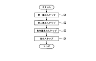
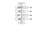
- FIG. 3 is a flowchart showing a control procedure by the control device of the endoscope system.
- 4 to 7 are diagrams for explaining the operation of the endoscope system.
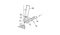
- An endoscope system 1 is a medical system used for surgery or the like. As shown in FIG. 1, the endoscope system 1 includes a first endoscope 10, an arm 20, a first image processing device 25, a first sub monitor 26, a second endoscope 30, and a second endoscope. An image processing device 36, a second sub-monitor 37, a position / orientation detection device 41, a main monitor 45, and a control device 50 are provided.
- the first endoscope 10 acquires an image (narrow angle image) in which a narrow region including a treatment site is an imaging target (narrow angle image), and supplies the first sub monitor and the main monitor 45. It is an endoscope for displaying.
- the first endoscope 10 is connected to the first image processing device 25 via a signal line SL1. Furthermore, the first image processing device 25 and the control device 50 are connected via a signal line SL1 ′.
- the first endoscope 10 has an insertion part 11 and a drive part 15.
- the insertion portion 11 is a long portion that is inserted from outside the body into the body of a patient to be treated.
- the insertion unit 11 includes an imaging unit 12 (first imaging unit), a joint unit 13, and a shaft unit 14.
- the imaging unit 12 has, for example, an image sensor and an objective optical system (both not shown) in order to acquire an image with the treatment site as an imaging target site.
- the image sensor of the imaging unit 12 can acquire, for example, a bright field image of the imaging target part.
- the objective optical system of the imaging unit 12 has a predetermined optical axis L1.
- the center of the visual field of the image captured by the imaging unit 12 is the position of the optical axis L1 of the imaging unit 12.
- the image captured by the imaging unit 12 is transmitted to the first image processing device 25 described later, and further transmitted to the control device 50.
- the angle of view of the imaging unit 12 of the first endoscope 10 may be the same as the angle of view of the imaging unit 32 of the second endoscope 30 or different from the angle of view of the imaging unit 32 of the second endoscope 30. May be.
- the narrow-angle image captured by the imaging unit 12 of the first endoscope 10 is an image in which a part of the image captured by the imaging unit 32 of the second endoscope 30 is an imaging field of view.
- the angle of view of the imaging unit 12 of the first endoscope 10 is not limited to mean that the angle of view of the imaging unit 32 of the second endoscope 30 is narrower.
- the joint portion 13 has a plurality of joint elements connected to each other via a rotating shaft.
- the joint portion 13 can be deformed so as to move the imaging unit 12 with respect to the shaft portion 14.
- the joint unit 13 is operable to adjust the position of the imaging unit 12 and the direction of the imaging field of view.
- An operation wire 18 is connected to the joint portion 13 for transmitting a force for operating the joint portion 13.
- the shaft portion 14 has a hard cylindrical shape in order to guide the imaging unit 12 to the vicinity of the treatment site in the body. Inside the shaft portion 14, there are wired a signal line (not shown) from the imaging unit 12, an operation wire 18 for connecting the joint portion 13 to a driving portion 15 described later in order to operate the joint portion 13, and the like. Yes.
- the drive unit 15 is disposed at the end of the insertion unit 11 opposite to the imaging unit 12 (referred to as the base end of the first endoscope 10 in this embodiment).
- the drive unit 15 is fixed to the shaft unit 14.
- a signal line (not shown) extending from the imaging unit 12 and an operation wire 18 extending from the joint unit 13 are wired.
- the drive unit 15 includes an actuator 16 connected to the operation wire 18 for moving the operation wire 18, and an encoder 17 for detecting an operation amount of the actuator 16.
- the actuator 16 provided in the drive unit 15 operates according to control by the control device 50.
- the drive unit 15 also has a function as an adapter for attaching the first endoscope 10 to the arm 20.
- the first endoscope 10 of the present embodiment does not need to have a structure for incising or suturing the treatment site directly.
- the insertion unit 11 may have a treatment tool (not shown) for incising or suturing the treatment site at the distal end.
- the insertion part 11 may have a channel for inserting a known endoscope treatment tool.
- the first endoscope 10 may be configured to rotate the imaging field of the imaging unit 12 with the center of the field of view as the rotation center (for example, with the optical axis L1 of the imaging unit 12 as the rotation center).
- the rotation of the imaging field of view may be a configuration in which the imaging unit 12 is mechanically rotated, or a configuration in which an image acquired by the image sensor of the imaging unit 12 is rotated by image processing.
- the arm 20 holds the first endoscope 10 in a desired position and posture, and moves the first endoscope 10 in a desired direction.
- the arm 20 is connected to the control device 50 via the signal line SL2.
- the arm 20 includes a link portion 21, a joint portion 22, an actuator 23, and an encoder 24.
- the link part 21 includes a plurality of proximal side link parts 21 a having a detachable structure to which the drive part 15 of the first endoscope 10 can be attached and the joint elements constituting the joint part 22. And a link portion 21b.
- the joint portion 22 connects two adjacent link portions 21 so as to be bendable, for example. Moreover, some of each joint part 22 which comprises the several joint part 22 may connect two adjacent link parts 21 so that each centerline may make coaxial, so that rotation is possible.
- the upper limit of the degree of freedom of the arm 20 is not particularly limited. The arrangement, the number, and the like of the joint portions 22 may be such that the arm 20 can be provided with the minimum degree of freedom necessary for controlling the position and posture of the first endoscope 10.
- the actuator 23 is disposed in the joint portion 22.
- the actuator 23 operates the joint portion 22 according to the operation control by the control device 50.
- the encoder 24 is disposed at the plurality of joint portions 22.
- encoders 24 are arranged at all joint portions 22 included in the arm 20.
- the encoder 24 is electrically connected to a control device 50 described later.
- the encoder 24 outputs the movement amount of each joint portion 22 to the control device 50.
- the encoder 24 may output a signal indicating the absolute angle of each joint portion 22 to the control device 50.
- the first image processing device 25 is connected to the imaging unit 12 of the first endoscope 10.
- the first image processing device 25 receives image information captured by the image capturing unit 12 of the first endoscope 10 from the image capturing unit 12 and outputs the image information to the first sub-monitor 26 as a video signal. Is output to the image control unit 52.
- the first sub-monitor 26 displays a video based on the video signal output from the first image processing device 25.
- the first sub-monitor 26 can display a narrow-angle image including the treatment site.
- the second endoscope 30 acquires an image (wide-angle image) that captures a wide area including the treatment site and displays the acquired image on the second sub-monitor and the main monitor 45. It is an endoscope for.
- the second endoscope 30 is connected to the second image processing device 36 via a signal line SL3. Further, the second image processing device 36 and the control device 50 are connected via a signal line SL3 ′.
- the second endoscope 30 has an insertion part 31 and an operation part 34.
- the insertion portion 31 of the second endoscope 30 has an elongated rod shape as a whole.
- the insertion part 31 of the second endoscope 30 in the present embodiment has, for example, a hard property. That is, in the present embodiment, the second endoscope 30 is a rigid endoscope.
- the insertion part 31 of the second endoscope 30 has an imaging part 32 (second imaging part) and a shaft part 33.
- the imaging unit 32 of the second endoscope 30 has, for example, an image sensor and an objective optical system (both not shown) in order to acquire an image of the treatment site.
- the image sensor of the imaging unit 32 of the second endoscope 30 can acquire, for example, a bright field image of the imaging target part.
- the objective optical system of the imaging unit 32 has a predetermined optical axis L2.
- the center of the visual field of the image captured by the imaging unit 32 is the position of the optical axis L ⁇ b> 2 of the imaging unit 32.
- the image captured by the imaging unit 32 of the second endoscope 30 is transmitted to the control device 50 described later.
- the angle of view of the imaging unit 32 of the second endoscope 30 may be the same as the angle of view of the imaging unit 12 of the first endoscope 10 or different from the angle of view of the imaging unit 12 of the first endoscope 10. May be.
- the wide-angle image captured by the imaging unit 32 of the second endoscope 30 is an image that captures a wider range than the imaging field of view of the imaging unit 12 of the first endoscope 10.
- the angle of view of the imaging unit 32 of the endoscope 30 is not limited to that which means that the angle of view of the imaging unit 12 of the first endoscope 10 is wider.
- the shaft portion 33 of the second endoscope 30 has a hard cylindrical shape in order to guide the imaging unit 32 of the second endoscope 30 to the vicinity of the treatment site in the body.
- a signal line (not shown) for connecting the imaging unit 32 of the second endoscope 30 to a control device 50 described later is wired inside the shaft portion 33 of the second endoscope 30.
- the operation unit 34 is an end of the insertion unit 31 of the second endoscope 30 opposite to the imaging unit 32 side (second endoscope in the present embodiment). (Referred to as the base end of the mirror 30).
- the operation part 34 has a grip part 35.
- the grip part 35 is a part that can be gripped by an operator who operates the second endoscope 30.
- the operator can move the entire insertion portion 31 of the second endoscope 30 by gripping and moving the grip portion 35.
- the imaging field of view of the imaging unit 32 of the second endoscope 30 can be moved by the operator holding and moving the holding unit 35.
- a viewpoint changing switch 39 and a field matching switch 40 which will be described later, may be disposed on the grip portion 35.
- the configuration of the second endoscope 30 is not limited to the above configuration.
- the second endoscope 30 may be a rigid endoscope or a flexible endoscope having the imaging unit 32 for capturing the wide-angle image.
- the direction of the visual field of the imaging unit 32 of the second endoscope 30 is fixed to the insertion unit 31 of the second endoscope 30 or can be grasped by the control device 50, It is not limited to the configuration.
- the second image processing device 36 is connected to the imaging unit 32 of the second endoscope 30.
- the second image processing device 36 receives the image information captured by the image capturing unit 32 of the second endoscope 30 from the image capturing unit 32 and outputs the image information to the second sub-monitor 37 as well as the image information. Is output to the image control unit 52.
- the second sub monitor 37 displays a video based on the video signal output from the second image processing device 36.
- the second sub-monitor 37 can display a wide-angle image including the treatment site.
- the arm input unit 38 is connected to the drive control unit 53 of the control device 50.
- the arm input unit 38 outputs a predetermined operation signal for operating the arm 20 to the drive control unit 53 by being operated by a scopist, for example.
- the viewpoint change switch 39 is electrically connected to the image control unit 52 of the control device 50.
- the viewpoint change switch 39 is a change-over switch that selects one desired image from the narrow-angle image obtained by the first endoscope 10 and the wide-angle image obtained by the second endoscope 30.
- the viewpoint change switch 39 is a push button switch, and switches the image displayed on the main monitor 45 to a wide-angle image or a narrow-angle image each time the viewpoint change switch 39 is pressed.
- the viewpoint change switch 39 is a position that is easy for a person (for example, a surgeon) who performs treatment to a treatment site, a person (for example, a scoopist) who operates the first endoscope 10 or the second endoscope 30, etc. Can be arranged.
- the viewpoint change switch 39 can be attached to a medical instrument operated by a surgeon who performs treatment on a treatment site. Further, the viewpoint change switch 39 may be disposed in the vicinity of the grip portion 35 of the second endoscope 30 (see FIG. 1). By changing the viewpoint change switch 39 of the present embodiment at a position that can be easily operated by an operator who operates the second endoscope 30, the viewpoint can be changed during the treatment using the second endoscope 30. Becomes easy.
- the visual field alignment switch 40 is electrically connected to the drive control unit 53 of the control device 50.
- the field matching switch 40 operates the first endoscope 10 so that the field center of the narrow-angle image obtained by the first endoscope 10 matches the field center of the wide-angle image obtained by the second endoscope 30. This is a switch for performing an input to the drive control unit 53 of the control device 50.
- the field alignment switch 40 is a position that is easy for a person (for example, a surgeon) who performs treatment to a treatment site, a person (for example, a scoopist) who operates the first endoscope 10 or the second endoscope 30, etc. Can be arranged.
- the field matching switch 40 is disposed in the vicinity of the grip portion 35 of the second endoscope 30.
- the field-of-view switch 40 is a push button switch, and each time the field-of-view switch 40 is pressed, the controller 50 controls the first endoscope 10 so that the center of the narrow-angle image matches the center of the wide-angle image. The movement is started.
- the visual field alignment switch 40 according to the present embodiment is arranged at a position that can be easily operated by an operator who operates the second endoscope 30, so that the field of view of the narrow-angle image during the treatment using the second endoscope 30. The center and the visual field center of the wide-angle image can be easily matched.
- the position / orientation detection device 41 detects the positions and orientations of the first endoscope 10 and the second endoscope 30 in a space such as an operating room in which the endoscope system 1 according to the present embodiment is installed.
- the position / orientation detection device 41 includes a first marker 42, a second marker 43, and a camera 44.
- the position / orientation detection device 41 is connected to a control device 50 described later.
- the first marker 42 is disposed on the drive unit 15 of the first endoscope 10.
- the first marker 42 is a marker different from the second marker 43 so that the first endoscope 10 and the second endoscope 30 can be distinguished.
- the configuration of the first marker 42 is not particularly limited as long as it can be imaged by the camera 44 and can be recognized by the control device 50.
- the first marker 42 may have a shape unique to the first marker 42, have a pattern with a predetermined shape, or emit predetermined light to the camera 44. Absent.
- the second marker 43 is disposed on the operation unit 34 of the second endoscope 30.
- the second marker 43 is a marker different from the first marker 42 so that the first endoscope 10 and the second endoscope 30 can be distinguished.
- the configuration of the second marker 43 is not particularly limited as long as it can be imaged by the camera 44 and can be recognized by the control device 50.
- the second marker 43 may have a shape unique to the second marker 43, have a pattern with a predetermined shape, or emit predetermined light to the camera 44. Absent.
- first marker 42 and the second marker 43 are indistinguishable from each other, they are associated with each other when the endoscope system 1 is used, and the positions and orientations of the respective markers are always used when the endoscope system 1 is used. If it comes to track.
- the camera 44 captures an image including the first marker 42 and the second marker 43 and transmits the image to the control device 50.
- the camera 44 acquires a plurality of images having different fields of view.
- the camera 44 includes two imaging devices having different fields of view.
- the camera 44 is fixed to a part of a space such as an operating room where the endoscope system 1 is arranged.
- the camera 44 is fixed to a part of the operating room and an image including the first marker 42 and the second marker 43 is captured, so that the first coordinate system in the predetermined coordinate system (reference coordinate system) with the position of the camera 44 as a reference.
- the positions and postures of the one marker 42 and the second marker 43 can be detected.
- the main monitor 45 is connected to the control device 50 through a signal line SL4.
- the main monitor 45 can display an image captured by the imaging unit 12 of the first endoscope 10 and an image captured by the imaging unit 32 of the second endoscope 30 via the image control unit 52.
- the main monitor 45 selects one image selected by the switching input by the viewpoint change switch 39 from the image captured by the first endoscope 10 and the image captured by the second endoscope 30. indicate.
- the display state on the main monitor 45 is controlled by the image control unit 52 of the control device 50.
- the specific configuration of the main monitor 45 is not particularly limited. For example, as the main monitor 45, a known display system that displays an image based on an analog or digital video signal may be appropriately selected.
- the control device 50 controls the arm 20 and the second endoscope 30. Furthermore, the control device 50 causes the main monitor 45 to display an image from the first endoscope 10, an image from the second endoscope 30, and the like.
- the control device 50 illustrated in FIGS. 1 and 2 includes a position calculation unit 51, an image control unit 52, and a drive control unit 53.
- the position calculation unit 51 receives an image signal from the camera 44 and calculates the positions of the first marker 42 and the second marker 43.
- the position calculation unit 51 stores the positions and orientations of the first marker 42 and the second marker 43 in a predetermined coordinate system (reference coordinate system) based on the position of the camera 44 as coordinate information.
- the image control unit 52 is connected to the first image processing device 25, the second image processing device 36, the drive control unit 53, the viewpoint change switch 39, and the main monitor 45. Furthermore, the image control unit 52 uses a predetermined information for operating the drive control unit 53 using the image information output from the first image processing device 25 and the image information output from the second image processing device 36. Information is generated and output to the drive control unit 53. Further, the image control unit 52 acquires an image captured by the first endoscope 10 and an image captured by the second endoscope 30, and outputs an image corresponding to the switching input by the viewpoint change switch 39 to the main monitor 45. Is output.
- the main monitor 45 may be composed of two screens, a main screen and a sub screen, and the image control unit 52 displays an image designated by the switching input by the viewpoint change switch 39 on the main screen, and by the switching input. An image that has not been selected may be displayed on the sub-screen.
- the drive control unit 53 is connected to the position calculation unit 51. Further, the drive control unit 53 is connected to the actuator 16 and encoder 17 of the first endoscope 10 and the actuator 23 and encoder 24 of the arm 20. Further, the drive control unit 53 is connected to the arm input unit 38. The drive control unit 53 controls the operation of the joint unit 13 of the first endoscope 10 and the arm 20 based on an operation signal generated by an operation by the operator on the arm input unit 38.
- the position calculation unit 51 recognizes the first marker 42 from the image captured by the camera 44 of the position and orientation detection device 41.
- the image transmitted from the camera 44 to the position calculation unit 51 includes a plurality of images having different fields of view.
- the position calculation unit 51 determines the position of the first marker 42 in the reference coordinate system and the position of the first marker 42 from the plurality of images. Recognize posture.
- the first marker 42 is disposed in the drive unit 15 of the first endoscope 10, and the position of the first endoscope 10 with respect to the position of the first marker 42 is stored in the control device 50 in advance.
- the position calculation unit 51 can recognize the position and posture of the first endoscope 10 based on the position and posture of the first marker 42.
- the position calculation unit 51 uses a predetermined reference point in the driving unit 15 of the first endoscope 10 as the position of the first endoscope 10. That is, the position calculation unit 51 recognizes the coordinates of the reference point of the first endoscope 10 in the reference coordinate system as the position of the first endoscope 10. Further, the position calculation unit 51 uses the direction of the first marker 42 in the reference coordinate system as the posture of the first endoscope 10.
- the drive control unit 53 refers to the encoder 17 provided in the joint portion 13 of the first endoscope 10, so that the distal end portion of the joint portion 13 is added to the position and posture of the first endoscope 10.
- the position and orientation of the imaging unit 12 arranged in the are recognized.
- the drive control unit 53 recognizes some coordinates of the imaging unit 12 in the reference coordinate system as the position of the imaging unit 12. Further, the drive control unit 53 recognizes the direction of the optical axis in the reference coordinate system as the posture of the imaging unit 12.
- the position / orientation detection device 41, the position calculation unit 51, and the drive control unit 53 constitute a first position / orientation detection unit that detects the position and orientation of the first endoscope 10 in the reference coordinate system.
- the control apparatus 50 can detect the position and attitude
- the position calculation unit 51 recognizes the second marker 43 from the image captured by the camera 44 of the position and orientation detection device 41.
- the position calculation unit 51 recognizes the position and orientation of the second marker 43 in the same manner as the recognition of the position and orientation of the first marker 42.
- the drive control unit 53 recognizes some coordinates of the imaging unit 32 of the second endoscope 30 in the reference coordinate system as the position of the imaging unit 32 of the second endoscope 30. Further, the drive control unit 53 recognizes the direction of the optical axis in the reference coordinate system as the posture of the imaging unit 32 of the second endoscope 30.
- the position / orientation detection device 41, the position calculation unit 51, and the drive control unit 53 constitute second position / orientation detection means for detecting the position and orientation of the second endoscope 30 in the reference coordinate system.
- the control device 50 can detect the position and posture of the optical axis L2 of the second endoscope 30.
- the drive control unit 53 receives an input to the arm input unit 38 disposed on the grip unit 35 of the second endoscope 30 and operates the first endoscope 10 and the arm 20 based on this input. Further, the drive control unit 53 receives an input to the visual field alignment switch 40 disposed on the grip unit 35 of the second endoscope 30 and operates the first endoscope 10 and the arm 20 based on this input. As shown in FIG. 3, the drive control unit 53 that has received an input to the field matching switch 40 operates the first endoscope 10 and the arm 20 as shown in each step from step S1 to step S4.
- the drive control unit 53 recognizes the position and orientation of the first endoscope 10 in the reference coordinate system and the position and orientation of the optical axis L1 of the first endoscope 10 in the reference coordinate system (first calculation step). , Step S1). Further, the drive control unit 53 recognizes the position and orientation of the optical axis L2 of the second endoscope 30 in the reference coordinate system (second calculation step, step S2). In addition, step S2 may be performed before said step S1, and may be performed after said step S1.
- step S1 and step S2 the drive control unit 53 operates the first endoscope 10 and the arm 20 so as to approach the position and posture of the optical axis L2 of the second endoscope 30 recognized in step S2. Is calculated (operation amount calculation step, step S3).
- step S ⁇ b> 3 the drive control unit 53 moves the first endoscope 10 at a position shifted by a predetermined distance toward the front side in the optical axis direction with respect to the coordinates indicating the position of the optical axis L ⁇ b> 2 of the second endoscope 30. Is set to the movement target position of the optical axis L1.
- step S3 the drive control unit 53 sets the movement target position of the optical axis L1 of the first endoscope 10 in a region between the distal end of the imaging unit 32 of the second endoscope 30 and the imaging target site.
- the movement target position set by the drive control unit 53 in step S3 is the coordinates of one point on the optical axis L2 of the second endoscope 30 in the reference coordinate system.
- the accuracy of the movement target position set by the drive control unit 53 in step S3 may not be so strict. This is because if the optical axis L1 of the first endoscope 10 and the optical axis L2 of the second endoscope 30 are parallel, the center of the field of view on the image is practical even if the distance between the optical axes is somewhat apart. This is because the difference is within the range of no problem.
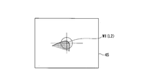
- the movement target position set by the drive control unit 53 in step S3 may be set as an area within a certain range in order to allow a certain amount of error. For example, as shown in FIG.
- the movement target position X1 set by the drive control unit 53 in step S3 is centered on the optical axis along a plane orthogonal to the optical axis L2 of the second endoscope 30 in the reference coordinate system.
- the coordinates in a circle C1 having a predetermined diameter may be used.
- the movement target position set by the drive control unit 53 in step S3 may be coordinates in a sphere centered on the coordinates of the position of the optical axis L2 of the second endoscope 30 in the reference coordinate system.
- the movement target position set by the drive control unit 53 in step S3 may be coordinates in a cylinder with the optical axis L2 of the second endoscope 30 as the center line in the reference coordinate system.
- the second endoscope 30 since an error can be allowed when determining that the position of the optical axis L1 of the first endoscope 10 has reached the optical axis L2 of the second endoscope 30, for example, the second endoscope 30 is operated. Therefore, it is possible to prevent the movement of the optical axis L1 of the first endoscope 10 from being completed due to the movement of the optical axis L2 of the second endoscope 30 due to the hand shake of the operator who performs the operation. Further, in this case, when both the image from the first endoscope 10 and the image from the second endoscope 30 are displayed on the main monitor 45, due to camera shake when operating the second endoscope 30. It is also possible to reduce image disturbance due to the imaging unit 12 of the first endoscope 10 continuing to move following the optical axis L2 of the second endoscope 30.
- step S3 the drive control unit 53 sets a movement path from the current position of the optical axis L1 of the first endoscope 10 to the movement target position.
- the method for setting the movement path from the current position of the optical axis L1 of the first endoscope 10 to the movement target position is not particularly limited as long as there is no obstacle in the movement path.
- the drive control unit 53 moves the first endoscope 10 so that the optical axis moves along the movement path. Twenty movement amounts are calculated.
- step S3 the drive control unit 53 operates the target direction of the imaging unit 12 so that the direction of the optical axis L1 of the first endoscope 10 matches the direction of the optical axis L2 of the second endoscope 30.
- the drive control unit 53 determines that the direction of the optical axis L1 of the first endoscope 10 when the optical axis L1 of the first endoscope 10 is positioned at the movement target position is the second inner position.
- the joint drive amount of the joint unit 13 for rotating the imaging unit 12 around the coordinates indicating the position of the optical axis L1 of the first endoscope 10 so as to be parallel to the direction of the optical axis L2 of the endoscope 30 is set. calculate.
- step S3 the operation target direction of the imaging unit 12 set by the drive control unit 53 in step S3 may be set as an area within a certain range in order to allow a certain amount of error.
- step S ⁇ b> 3 the drive control unit 53 calculates the operation amount of the arm 20 and the operation amount of the joint unit 13. Step S3 is complete
- step S4 an operation instruction for operating the arm 20 and the joint unit 13 is output to the arm 20 and the joint unit 13 based on the operation amount of the arm 20 and the operation amount of the joint unit 13 calculated in step S3.
- This is an instruction step.
- the drive control unit 53 operates the arm 20 and the joint unit 13 by outputting an operation instruction to the arm 20 and the joint unit 13.
- the drive control unit 53 first outputs an operation instruction to the arm 20, so that the position of the optical axis L1 of the first endoscope 10 is on the optical axis L2 of the second endoscope 30. The first endoscope 10 is moved until the movement target position is reached.
- the drive control unit 53 outputs an operation instruction to the joint unit 13, so that the optical axis L ⁇ b> 1 of the first endoscope 10 is coaxial with the optical axis L ⁇ b> 2 of the second endoscope 30.
- the imaging unit 12 of the first endoscope 10 is rotated on the optical axis L2 of the endoscope 30.
- the drive control unit 53 uses inverse kinematics to calculate the motion amount of each degree of freedom of the joint unit 13 and the arm 20 in order to move the arm 20 and the joint unit 13 in the motion direction calculated in step S3. To determine the control amount of each actuator. Based on this control amount, the drive control unit 53 outputs a drive signal.
- step S4 ends.
- the drive control unit 53 corresponds to the input to the visual field alignment switch 40 and the optical axis L1 of the first endoscope 10 and the second endoscope.
- the first endoscope 10 and the arm 20 are operated so that the 30 optical axes L2 are coaxial.
- the operation of the endoscope system 1 will be described together with the operation during use of the endoscope system 1.
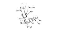
- the first endoscope 10 and the second endoscope 30 are inserted into the body. That is, the insertion part 11 of the first endoscope 10 and the insertion part 31 of the second endoscope 30 are inserted into the body through, for example, a trocar, and as shown in FIG. 4, the imaging part 32 of the second endoscope 30. Is guided to the vicinity of the treatment site in the body, and the imaging unit 12 of the first endoscope 10 is guided to a position closer to the treatment endoscope near the second endoscope 30.
- the first endoscope 10 and the second endoscope 30 may have optical functions such as zoom and macro, but an explanation in consideration of these optical functions will be described in this specification. Omitted.
- the operator For example, a surgeon or a scoopist
- the operator uses the second endoscope 30 to observe a wide area including the treatment site from a bird's-eye view.
- the operator mainly operates the second endoscope 30.
- the operator grasps the situation near the treatment site by moving the operation unit 34 of the second endoscope 30 and observing a desired site.
- the operator After grasping the status of the treatment site, the operator maintains the second endoscope 30 so that the treatment site is positioned at the center of the visual field of the image, and further performs input to the visual field matching switch 40. Then, the drive control part 53 controls the arm 20 and the 1st endoscope 10 according to the control procedure from said step S1 to step S4.
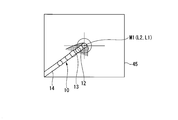
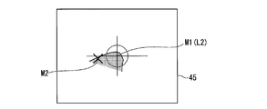
- the imaging unit 12 of the first endoscope 10 enters the field of view of the second endoscope 30. Furthermore, as shown in FIG. 6, when the optical axis L1 of the imaging unit 12 of the first endoscope 10 reaches the circle C1 centered on the point X1 on the optical axis L2 of the second endoscope 30, The movement of the imaging unit 12 stops, and then, as shown in FIG. 7, the first endoscope so that the optical axis L1 of the first endoscope 10 is coaxial with the optical axis L2 of the second endoscope 30. The orientation of the imaging unit 12 of the mirror 10 changes.
- the second endoscope In the state where the imaging unit 12 of the first endoscope 10 is arranged so that the optical axis L1 of the first endoscope 10 is coaxial with the optical axis L2 of the second endoscope 30, the second endoscope The imaging unit 12 of the first endoscope 10 is located at the center of the visual field of the image captured by the 30 imaging units 32. The operator can grasp that the imaging unit 12 of the first endoscope 10 is arranged in the vicinity of the treatment site from the wide-angle image captured by the imaging unit 32 of the second endoscope 30. In a state where the imaging unit 12 of the first endoscope 10 is in the vicinity of the treatment site, the operator inputs to the viewpoint change switch 39.
- the image control unit 52 of the control device 50 captures the image displayed on the main monitor 45 from the image captured by the imaging unit 32 of the second endoscope 30 by the imaging unit 12 of the first endoscope 10. Switch to the selected image. Since the optical axis L1 of the first endoscope 10 and the optical axis L2 of the second endoscope 30 are coaxial, the field center in the image captured by the imaging unit 12 of the first endoscope 10 is the first This coincides with the center of the visual field in the image captured by the imaging unit 32 of the two endoscopes 30.
- the display on the main monitor 45 includes a part including the center of the field of view of the wide-angle image.
- the image looks like an enlarged (zoomed-in) image.
- the image captured by the imaging unit 12 of the first endoscope 10 is a narrow-angle image in which the treatment site is captured in the field of view. The operator can perform treatment on the treatment site while viewing the image captured by the imaging unit 12 of the first endoscope 10.
- the operator can use the viewpoint change switch 39 to display an image to be displayed on the main monitor 45 from the narrow-angle image captured by the imaging unit 12 of the first endoscope 10 as necessary. Switching to a wide-angle image captured by the imaging unit 32 of the mirror 30 is possible. This can be performed, for example, when the state around the treatment site is confirmed during the treatment using the narrow-angle image.
- the imaging unit 32 of the second endoscope 30 uses a wide area including the imaging field of view of the first endoscope 10 as the imaging field. For this reason, the image displayed on the main monitor 45 is switched from the image captured by the image capturing unit 12 of the first endoscope 10 to the image captured by the image capturing unit 32 of the second endoscope 30.
- the display is an image in which the field of view of the narrow-angle image is widened (zoomed out).
- the operator holds and moves the operation unit 34 of the second endoscope 30 in a state where the image captured by the imaging unit 32 of the second endoscope 30 is displayed on the main monitor 45.
- the periphery of the treatment site can be observed.
- the first endoscope 10 is stopped in a state where a narrow-angle image in which the treatment site is captured at the center of the visual field can be acquired.
- a narrow-angle image including the treatment site is displayed on the main monitor 45 again.
- the operator first refers to the position of the imaging unit 12 of the first endoscope 10 based on the image captured by the imaging unit 32 of the second endoscope 30, and the second endoscope 30.
- the center of the visual field of the imaging unit 32 can be easily returned to the treatment site.
- the operator inputs to the viewpoint change switch 39 and displays an image displayed on the main monitor 45.
- the image captured by the image capturing unit 32 of the second endoscope 30 is switched to the image captured by the image capturing unit 12 of the first endoscope 10.
- the first endoscope 10 is stopped in a state where a narrow-angle image in which the treatment site is captured at the center of the visual field can be acquired. That is, the first endoscope 10 maintains the positional relationship before switching from the narrow-angle image to the wide-angle image. For this reason, after the image displayed on the main monitor 45 is switched from the wide-angle image to the narrow-angle image, the operator can easily restart the treatment.
- the positional relationship between the treatment site and the first endoscope 10 changes, and the first endoscope
- the position and posture of the treatment site in the image captured by the ten imaging units 12 may change.
- the operator inputs to the visual field alignment switch 40 in a state where the treatment site is captured at the center of the visual field of the imaging unit 32 of the second endoscope 30, and the imaging unit of the first endoscope 10 is input to the treatment site. 12 can be moved.
- the drive control unit 53 controls the arm 20 and the first endoscope 10 according to the control procedure from step S1 to step S4 described above, so that the optical axis L2 of the imaging unit 32 of the second endoscope 30 and The optical axis L1 of the imaging unit 12 of the first endoscope 10 is coaxial.
- the viewpoint change switch 39 By inputting to the viewpoint change switch 39 in this state, a narrow-angle image in which the treatment site is captured at the center of the visual field is displayed on the main monitor 45, and the new site can be treated.
- the operator needs to perform another treatment using the new site as the treatment site.
- the operator performs input to the field matching switch 40 in a state where the new part as a treatment part is captured at the center of the visual field of the imaging unit 32 of the second endoscope 30.
- the imaging unit 12 of the first endoscope 10 can be moved to a new site.
- the drive control unit 53 controls the arm 20 and the first endoscope 10 according to the control procedure from step S1 to step S4 described above, so that the optical axis L2 of the imaging unit 32 of the second endoscope 30 and The optical axis L1 of the imaging unit 12 of the first endoscope 10 is coaxial.
- a narrow-angle image capturing a new part as a treatment part with the center of the visual field being displayed is displayed on the main monitor 45, so that the new part can be treated.
- a surgeon who performs treatment using the endoscope system 1 according to the present embodiment can perform treatment while viewing a wide-angle image and a narrow-angle image including a treatment site by using the main monitor 45. it can.
- the scopist who operates the first endoscope 10 and the second endoscope 30 of the endoscope system 1 according to the present embodiment uses the first sub-monitor 26 and the second sub-monitor 37 to perform the treatment by the surgeon. Can adjust the position and posture of each endoscope independently or in cooperation with a surgeon's procedure.
- the optical axes of the two endoscopes are coaxial with each other, and a narrow-angle image and a wide-angle image are respectively displayed. Since the image is captured, when the image control unit 52 switches the image displayed on the main monitor 45 based on the input to the viewpoint change switch 39, an operation such as zooming out the narrow-angle image or zooming in on the wide-angle image A feeling can be obtained.
- the burden on the operator is small.
- a close visual field In a case where treatment is performed using a single endoscope in a conventional laparoscopic operation, during a procedure such as a peeling operation or blood vessel exposure in a close visual field (narrow angle visual field) In some cases, it is necessary to check the state of surrounding tissue or to check the running of the blood vessel currently being treated. In this case, the endoscope that has been brought close to is moved away, and observation is performed at a position where the whole can be seen, and the operation of returning the endoscope to the original position is performed after confirming the surrounding tissue and blood vessel running. .
- the first close visual field was the operative field (visual field) created by instructing the scopist to be easy to treat. However, by observing the whole, the field of view created first has been destroyed.
- the surgeon In order to reproduce the condition (field of view) that is easy to treat after the overall observation, the surgeon must repeat the instructions to the scopist, and it takes a long time to be able to return to the treatment. Accumulate. For this reason, in order to avoid this stress and fatigue, the surgeon wants to avoid losing his field of vision with a small amount of confirmation, and may give up even if he wants to confirm the whole.
- the surrounding tissue can be appropriately confirmed using the wide-angle image, so there is a possibility that safer surgery can be performed.
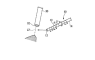
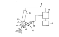
- FIG. 8 is a schematic diagram showing a part of the endoscope system according to the present embodiment.
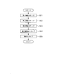
- FIG. 9 is a flowchart showing a control procedure by the control device of the endoscope system.
- the endoscope system 2 includes distance measuring means for measuring the distance to the imaging target region, the first endoscope 10, the second endoscope 30, and The controller 66 is provided.
- the imaging unit 60 having a configuration different from that of the imaging unit 12 disclosed in the first embodiment is replaced with the imaging unit 12 of the first embodiment.
- the second endoscope 30 of the present embodiment includes an imaging unit 63 having a configuration different from that of the imaging unit 32 disclosed in the first embodiment, instead of the imaging unit 32 of the first embodiment. Yes.
- the endoscope system 2 considers the distance to the imaging target based on the images captured by the imaging units 60 and 63 of the present embodiment, and the first endoscope 10 and the arm 20.
- a control device 66 including a step of operating (see FIG. 1) in the operation procedure is provided instead of the control device 50 of the first embodiment.
- the imaging unit 60 of the first endoscope 10 is different in configuration from the imaging unit 12 of the first endoscope 10 disclosed in the first embodiment in that it can acquire three-dimensional information of the imaging target part. ing.
- the first endoscope 10 includes a left imaging unit 61 and a right imaging unit 62.
- the left imaging unit 61 and the right imaging unit 62 capture a pair of images having parallax with respect to the same imaging target part.
- the left imaging unit 61 and the right imaging unit 62 each independently have an image sensor and an objective optical system.
- the image captured by the left imaging unit 61 and the image captured by the right imaging unit 62 are transmitted to the image control unit 67 of the control device 66 through a signal line (not shown) as in the first embodiment.
- the imaging unit 63 of the second endoscope 30 includes a left imaging unit 64 and a right imaging unit 65, for example, like the imaging unit 60 of the first endoscope 10.
- the image control unit 67 of the control device 66 measures the distance from the first endoscope 10 to the imaging target region based on the images acquired by the left imaging unit 61 and the right imaging unit 62 of the first endoscope 10, respectively.
- the image control unit 67 of the control device 66 measures the distance to the imaging target region using the parallax of the images acquired by the left imaging unit 61 and the right imaging unit 62 of the first endoscope 10.
- the image control unit 67 of the control device 66 is configured so that the distance from the second endoscope 30 to the imaging target region is based on the images acquired by the left imaging unit 64 and the right imaging unit 65 of the second endoscope 30, respectively. It has a function to measure. As an example, the image control unit 67 of the control device 66 measures the distance to the imaging target region using the parallax of the images acquired by the left imaging unit 64 and the right imaging unit 65 of the second endoscope 30.
- the configuration for measuring the distance between the first endoscope 10 and its imaging target site or the distance between the second endoscope 30 and its imaging target site is not limited to the above configuration.
- the first endoscope 10 and the second endoscope 30 may appropriately have a configuration such as a known laser range finder or infrared range finder.
- control device 66 of the present embodiment for moving the first endoscope 10 and the arm 20 will be described focusing on portions different from the control procedure in the first embodiment.
- the control device 66 includes the steps from Step S1 to Step S4 disclosed in the first embodiment in the control procedure.
- the endoscope system 2 according to the present embodiment has a positional relationship in which the optical axes of the first endoscope 10 and the second endoscope 30 coincide with each other with the treatment site being centered on the visual field.
- a narrow-angle image and a wide-angle image can be taken and either one or both of the narrow-angle image and the wide-angle image can be displayed on the main monitor 45.
- the first endoscope 10 and the second endoscope 30 both follow the movement of the second endoscope 30 in a state where an image in which the treatment site is captured at the center of the visual field is captured.
- the control procedure (see FIG. 9) when the control device 66 operates the first endoscope 10 and the arm 20 is different from that in the first embodiment.
- the control device 66 and the imaging target region of the first endoscope 10 The distance from the endoscope 10 is measured. For example, the control device 66 determines a predetermined image in a set of two images captured by the imaging unit 60 of the first endoscope 10 from the coordinates of the position of the optical axis of the imaging unit 60 of the first endoscope 10 in the reference coordinate system. The distance to the visual field center of one of the images is calculated (first ranging step, step S11, see FIG. 9). Furthermore, the control device 66 measures the distance between the imaging target portion of the second endoscope 30 and the second endoscope 30.
- control device 66 determines a predetermined value in a set of two images captured by the imaging unit 63 of the second endoscope 30 from the coordinates of the position of the optical axis of the imaging unit 63 of the second endoscope 30 in the reference coordinate system.
- the distance to the center of the visual field of one of the images is calculated (second distance measuring step, step S12, see FIG. 9).
- Step S12 may be executed before step S11 described above, or may be executed after step S11 described above.
- the first endoscope 10 and the second endoscope 30 both grasp the treatment site at the center of the visual field, and the respective distances calculated in the above steps S11 and S12 are respectively , The distance between the first endoscope 10 and the treatment site, and the distance between the second endoscope 30 and the treatment site.
- the operator moves the second endoscope 30 and starts treatment using a new part as a treatment part, the operator treats the center of the visual field of the image captured by the imaging unit 63 of the second endoscope 30 as a treatment.
- the second endoscope 30 is operated so as to match with a new part to be a part. Thereafter, the operator performs input to the visual field alignment switch 40.
- step S13 the control device 66 detects the position and orientation of the optical axis L2 of the second endoscope 30 in the same manner as in the first embodiment.
- step S ⁇ b> 13 a new treatment site is located at the center of the field of view of the image captured by the imaging unit 63 of the second endoscope 30. For this reason, in step S13, the distance between the second endoscope 30 and the new treatment site is calculated.
- step S13 the drive control unit 68 of the control device 66 operates the first endoscope 10 and the arm 20 so as to approach the position and posture of the optical axis L2 of the second endoscope 30 recognized in step S13.
- the operation amount for this is calculated (see step S14, FIG. 9).
- step S ⁇ b> 14 the drive control unit 68 sets the first endoscope 10 at a position shifted by a predetermined distance toward the front side in the optical axis direction with respect to the coordinates indicating the position of the optical axis L ⁇ b> 2 of the second endoscope 30. Is set to the movement target position of the optical axis L1.
- the control device 66 controls the second endoscope 30. For example, a message that prompts the user to move the first endoscope 10 or the second endoscope 30 is displayed on the main monitor 45 so as to move away from the imaging target region. In this case, the control device 66 returns to the above step S12 to recalculate the distance between the second endoscope 30 and its imaging target site, and to set the coordinates indicating the position of the optical axis L2 of the second endoscope 30.
- step S14 the control device 66 sets the movement target position of the optical axis L1 of the first endoscope 10 in the region between the tip of the imaging unit 63 of the second endoscope 30 and the imaging target site.
- the drive control unit 68 of the control device 66 sets a movement path from the current position of the optical axis L1 of the first endoscope 10 to the movement target position.
- the method for setting the movement path from the current position of the optical axis L1 of the first endoscope 10 to the movement target position takes into account that there are no obstacles in the movement path.
- the travel route set in step S14 may be set by the same setting method as the travel route set in step S3 in the first embodiment. After the movement path of the optical axis L1 of the first endoscope 10 is set, the drive control unit 68 moves the first endoscope 10 so that the optical axis moves along the movement path. Twenty movement amounts are calculated.
- step S14 the drive control unit 68 sets the first endoscope 10 so that the direction of the optical axis L1 of the first endoscope 10 coincides with the direction of the optical axis L2 of the second endoscope 30.
- the operation target direction of the imaging unit 60 is set.
- the drive control unit 68 determines that the direction of the optical axis L1 of the first endoscope 10 is the second inner point when the optical axis L1 of the first endoscope 10 is positioned at the movement target position.
- Step S ⁇ b> 14 the drive control unit 68 calculates the movement amount of the arm 20 and the movement amount of the joint portion 13. Step S14 is completed now and it progresses to Step S15.
- step S15 an operation instruction for operating the arm 20 and the joint portion 13 is output to the arm 20 and the joint portion 13 based on the movement amount of the arm 20 and the motion amount of the joint portion 13 calculated in step S14.
- This is an instruction step (see FIG. 9).
- the drive control unit 68 operates the arm 20 and the joint unit 13 by outputting an operation instruction to the arm 20 and the joint unit 13.
- the drive control unit 68 first outputs an operation instruction to the arm 20, so that the position of the optical axis L1 of the first endoscope 10 is on the optical axis L2 of the second endoscope 30. The first endoscope 10 is moved until the movement target position is reached.
- the drive control unit 68 outputs an operation instruction to the joint unit 13, so that the optical axis L ⁇ b> 1 of the first endoscope 10 is coaxial with the optical axis L ⁇ b> 2 of the second endoscope 30.
- the imaging unit 60 of the first endoscope 10 is rotated on the optical axis L2 of the endoscope 30.
- the drive control unit 68 corresponds to the input to the visual field alignment switch 40 and the optical axis L1 of the first endoscope 10 and the second endoscope.
- the first endoscope 10 and the arm 20 are operated until the 30 optical axes L2 are coaxial.
- the distance between the first endoscope 10 and the treatment site before the operation of the first endoscope 10 and the arm 20, and the first inner after the operation of the first endoscope 10 and the arm 20 are performed.
- the distance between the endoscope 10 and the new treatment site is equal to each other. For this reason, when a new treatment is performed using the image captured by the imaging unit 60 of the first endoscope 10, it is easy to grasp the status of the treatment site.
- the endoscope system 2 according to the present modification is configured such that a treatment path is used to move the imaging unit 60 of the first endoscope 10 from a certain treatment site (first site) to another new treatment site (second site).
- the imaging unit 60 of the first endoscope 10 can be moved while keeping the distance to the tissue including the region constant.
- the drive control unit 68 is based on the image captured by the imaging unit 60 of the first endoscope 10 in step S14 in the second embodiment.
- the optical axis L1 of the first endoscope 10 is always such that the distance between the line connecting the first part and the second part, for example, by the shortest path, and the position of the optical axis L1 of the first endoscope 10 always coincide. Set the travel route.
- the imaging unit 60 of the first endoscope 10 corresponds to the obstacle having the irregularities. It can move while avoiding obstacles with unevenness.
- the drive control unit 68 removes an obstacle having irregularities on the line connecting the first site and the second site of the tissue from the imaging unit 60 of the first endoscope 10.
- the first endoscope 10 may be moved while recognizing based on the image and avoiding an obstacle having unevenness.
- the drive control unit 68 calculates the distance between the first endoscope 10 and the tissue by calculating the distance from the tissue while appropriately adjusting the direction of the imaging unit 60 in the process of moving the first endoscope 10.
- the first endoscope 10 is moved while keeping the distance constant.
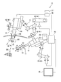
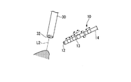
- FIG. 10 is a schematic overall view showing the endoscope system according to the present embodiment.
- FIG. 11 is a flowchart showing a control procedure by the control device 80 of the endoscope system.
- the endoscope system 3 according to the present embodiment shown in FIG. 10 is provided with an arm (second arm 71) for moving the second endoscope 30, and the endoscope according to the first embodiment described above.
- the configuration is different from the mirror system 1. That is, the endoscope system 3 according to the present embodiment includes the first endoscope 10 and the second endoscope 30 disclosed in the first embodiment, and the first for moving the first endoscope 10.
- the arm 70, the 2nd arm 71 for moving the 2nd endoscope 30, and the control apparatus 80 are provided.
- the configurations of the first endoscope 10 and the second endoscope 30 are the same as those in the first embodiment.
- the first endoscope 10 and the second endoscope 30 in the present embodiment may be the same type machine having the same configuration.
- the first arm 70 has the same configuration as the arm 20 disclosed in the first embodiment.
- the second arm 71 has the same configuration as the arm 20 disclosed in the first embodiment. That is, the second arm 71 has a link part 72, a joint part 73, an actuator 74, and an encoder 75.
- the operation part 34 of the second endoscope 30 can be attached to the link part 72 of the second arm 71.
- the second arm 71 is connected to the control device 80.
- the control device 80 included in the endoscope system 3 controls operations of the first endoscope 10, the second endoscope 30, the first arm 70, and the second arm 71.
- the control device 80 can output an operation instruction for operating the first endoscope 10 and the first arm 70 to the first endoscope 10 and the arm 20 in the same manner as in the first embodiment.
- the drive control unit 83 of the present embodiment outputs an operation instruction for operating the second arm 71 to the second arm 71.
- the drive control unit 83 is provided in the second endoscope 30.
- the above-described joint portion may be controlled.
- the control device 80 of the endoscope system 3 includes a control procedure for operating the second arm 71. That is, the control device 80 is configured so that the first endoscope 10 is capturing a narrow-angle image including the treatment site, and the optical axis L1 of the imaging unit 12 of the first endoscope 10 and the second endoscope. The second endoscope 30 is moved by operating the second arm 71 so that the optical axis L2 of the 30 imaging units 32 is coaxial.
- the control procedure for moving the second endoscope 30 includes the following steps from step S21 to step S24.
- the control device 80 recognizes the position and direction of the optical axis L1 of the first endoscope 10 based on an image including the first marker 42 captured by the camera 44 of the position and orientation detection device 41 (first calculation).
- Step, step S21 see FIG. 11).
- the control device 80 recognizes the position and posture of the second endoscope 30 based on an image including the second marker 43 imaged by the camera 44 of the position and posture detection device 41 (second calculation step, step S22).
- Step S22 may be executed before step S21 or may be executed after step S21.
- the drive control unit 83 of the control device 80 causes the optical axis L1 of the imaging unit 12 of the first endoscope 10 and the optical axis L2 of the imaging unit 32 of the second endoscope 30 to be coaxial. Then, the operation amount of the second endoscope 30 is calculated (operation amount calculation step, step S23, see FIG. 11).
- the drive control unit 83 of the control device 80 causes the position and direction of the optical axis L2 of the second endoscope 30 to pass through the position of the optical axis L1 of the first endoscope 10 in the reference coordinate system.
- the amount of movement of the second endoscope 30 is calculated so as to be parallel to the direction of the optical axis.
- the operation amount of the second arm 71 to which the second endoscope 30 is attached is calculated. Step S23 is ended now and it progresses to Step S24.
- Step S24 is an instruction step for outputting, to the second arm 71, an operation instruction for operating the second arm 71 based on the operation amount calculated in step S23 (see FIG. 11).
- the motion amount calculated in step S23 is converted into the motion amount of each joint portion 22 of the second arm 71, and the actuator 23 provided in each joint portion 22 of the second arm 71 respectively. It is output as an operation instruction. Accordingly, the second arm 71 operates in accordance with the operation instruction output in step S24, and the second arm 71 moves the second endoscope 30.
- the control device 80 causes the optical axis of the imaging unit 32 of the second endoscope 30 to move.
- the second endoscope 30 can be operated following the operation of the first endoscope 10 so that L2 is coaxial with the optical axis L1 of the imaging unit 12 of the first endoscope 10.
- the control device 80 of the present embodiment mainly sets one of the first endoscope 10 and the second endoscope 30, and mainly sets the first endoscope 10 and the second endoscope 30.
- the person who was not done is set as a subordinate.
- the endoscope set mainly between the first endoscope 10 and the second endoscope 30 is an endoscope operated by an operator, and the first endoscope 10 and the second endoscope 30 are connected to each other.
- the endoscope set as a slave is automatically controlled by the control device 80 so as to move following the movement of the optical axis L1 of the imaging unit 12 of the endoscope.
- the master-slave relationship between the first endoscope 10 and the second endoscope 30 is set based on the input state to the viewpoint change switch 39.
- the control device 80 when an input for making the image displayed on the main monitor 45 an image from the first endoscope 10 is made to the viewpoint change switch 39, 10 is set as the primary endoscope, and the second endoscope 30 is set as the secondary endoscope.
- the control device 80 when the input to change the image displayed on the main monitor 45 to the image from the second endoscope 30 is made to the viewpoint change switch 39, the control device 80 performs the second endoscope.
- the mirror 30 is set as the main endoscope
- the first endoscope 10 is set as the slave endoscope. In this way, the control device 80 sets the master-slave relationship between the first endoscope 10 and the second endoscope 30 based on the input state to the viewpoint change switch 39.
- control procedure by the control device 80 in the endoscope system 3 according to the present embodiment will be described in more detail together with the overall operation of the endoscope system 3.
- the optical axis L1 of the first endoscope 10 is coaxial with the optical axis L2 of the second endoscope 30.
- the imaging unit 12 of the first endoscope 10 can be moved. That is, the second endoscope 30 that captures a wide-angle image for observing the treatment site from a bird's-eye view is set as the main endoscope, and the second endoscope 30 that is the main endoscope is imaged.
- the first endoscope 10, which is a slave endoscope is automatically controlled by the control device 80 so as to be coaxial with the optical axis L2 of the unit 32.
- the imaging unit 12 of the first endoscope 10 that is the main endoscope moves, and the second endoscope 30 that is the slave endoscope captures the image of the first endoscope 10. It moves following the movement of the part 12.
- the second endoscope 30 is the second endoscope 30.
- the position and orientation are controlled by the control device 80 so that the optical axis L2 of the imaging unit 32 is coaxial with the optical axis L1 of the imaging unit 12 of the first endoscope 10. Therefore, when the operator inputs to the viewpoint change switch 39 and the image displayed on the main monitor 45 is switched from the narrow-angle image to the wide-angle image by the image control unit 82, the wide-angle image displayed on the main monitor 45 is The image is obtained by capturing the center of the field of view of the narrow-angle image as the center of the field of view.
- the image displayed on the main monitor 45 is switched by the image control unit 82 from an image captured by the imaging unit 12 of the first endoscope 10 to an image captured by the imaging unit 32 of the second endoscope 30.
- the display on the main monitor 45 becomes an image in which the field of view of the narrow-angle image is widened (zoomed out).
- the control device 80 sets the second endoscope 30 as the main endoscope in a state where the image captured by the imaging unit 32 of the second endoscope 30 is displayed on the main monitor 45.
- the first endoscope 10 is set as a slave endoscope. Furthermore, in a state where the image captured by the imaging unit 32 of the second endoscope 30 is displayed on the main monitor 45, the control device 80 does not change the state of the second endoscope 30 until there is an input to the field matching switch 40. The linkage between the movement and the movement of the first endoscope 10 is released.
- the operator stops the imaging unit 12 of the first endoscope 10 and stops the second
- the state around the treatment site can be observed by moving the endoscope 30.
- the operator inputs to the viewpoint change switch 39 and switches the image displayed on the main monitor 45.
- the main endoscope is switched from the second endoscope 30 to the first endoscope 10
- the slave endoscope is switched from the first endoscope 10 to the second endoscope 30.
- the second endoscope 30, which is a slave endoscope is automatically controlled by the control device 80.
- the optical axis L2 of the imaging unit 32 of the second endoscope 30 is the optical axis of the imaging unit 12 of the first endoscope 10 as in steps S21 to S24 in the present embodiment.
- the second arm 71 is controlled by the control device 80 so as to be coaxial with L1.
- Treatment can be resumed while viewing the included narrow-angle image. That is, the operation of returning the second endoscope 30 after operating the second endoscope 30 to observe the state around the treatment site is performed after the image displayed on the main monitor 45 is switched. It is automatically controlled by the control device 80 at the ground.
- the operator does not need to manually move the second endoscope 30 to return the second endoscope 30 to the original position, and the optical axis L2 of the second endoscope 30 is Since it automatically returns to a state where it is coaxial with the optical axis L1 of the endoscope 10, the center of the field of view of the narrow-angle image and the wide-angle image match when a wide-angle image is captured again.
- the main endoscope is the second endoscope 30, and the first endoscope 10 which is the slave endoscope is automatically controlled by the control device 80.
- the optical axis L1 of the imaging unit 12 of the first endoscope 10 is the same as that of the imaging unit 32 of the second endoscope 30 in the same manner as each step from step S1 to step S4 in the first embodiment.
- the first arm 70 and the joint portion 13 are controlled by the control device 80 so as to be coaxial with the optical axis L2.
- the control device 80 can be moved so as to follow the movement of the imaging unit 12 of the one endoscope 10.
- the deviation between the visual field center of the imaging unit 12 of the first endoscope 10 and the visual field center of the imaging unit 32 of the second endoscope 30 is always eliminated. State.
- the position of the second endoscope 30 is controlled by the control device 80. Is restored to its original position and posture by automatic control.
- the control device 80 performs an operation for moving the second endoscope 30 so that the second endoscope 30 is in a state where the original treatment site is captured at the center of the visual field. The operation burden can be reduced.
- the endoscope system 3 of this modification is different from the above embodiment in part of the control procedure for moving the second endoscope 30 following the movement of the imaging unit 12 of the first endoscope 10. Yes. That is, in the present modification, when the operator inputs to the visual field alignment switch 40, the optical axis L2 of the imaging unit 32 of the second endoscope 30 is the same as that of the imaging unit 12 of the first endoscope 10.
- the control device 80 operates the second arm 71 so as to be coaxial with the optical axis L1.
- step S21 and step S22 described above are triggered by the detection of the control device 80 that the operator has made an input to the visual field matching switch 40.
- the second endoscope 30 when the imaging unit 12 of the first endoscope 10 is moved, the second endoscope 30 is not used until the operator inputs to the field matching switch 40. Do not move.
- the second endoscope 30 in the state where only the narrow-angle image from the first endoscope 10 is displayed on the main monitor 45 when the treatment site is imaged using the imaging unit 12 of the first endoscope 10, the second There may be a case where it is not possible to grasp what posture the endoscope 30 is in the body, and it is not preferable to always move the second endoscope 30 automatically in the body.
- the drive control unit 83 of the control device 80 controls the second arm 71 so as to prohibit the operation of the second arm 71 that moves the second endoscope 30 when there is no input to the visual field alignment switch 40.
- the second arm 71 can be operated only when the second endoscope 30 needs to be moved by the second arm 71.
- the drive control unit 83 of the control device 80 operates the second arm 71 so that the optical axis L2 of the imaging unit 32 is coaxial with the optical axis L1 of the imaging unit 12 of the first endoscope 10.
- steps S21 and S22 the optical axis L1 of the imaging unit 12 of the first endoscope 10 and the optical axis L2 of the imaging unit 32 of the second endoscope 30 are separated by a predetermined distance or more. Is triggered by the detection of the drive control unit 83 via the position calculation unit 81.
- the distance between the optical axis L1 of the imaging unit 12 of the first endoscope 10 and the optical axis L2 of the imaging unit 32 of the second endoscope 30 is the position and orientation of the first endoscope 10 in the reference coordinate system, and
- the position calculation unit 81 or the drive control unit 83 calculates based on the position and orientation of the two endoscopes 30.
- the control device 80 is configured such that a deviation of a predetermined threshold value or more occurs between the optical axis L1 of the imaging unit 12 of the first endoscope 10 and the optical axis L2 of the imaging unit 32 of the second endoscope 30. Only the second endoscope 30 is moved.
- the control device 80 calculates the total sum of deviations accumulated from the most recent movement of the second endoscope 30 to the present as the movement amount to move the second endoscope 30. Furthermore, the control device 80 does not move the second endoscope 30 when the movement amount calculated based on the total sum of the deviations does not exceed a predetermined threshold, and based on the total sum of the deviations. When the calculated movement amount exceeds a predetermined threshold, the second endoscope 30 is moved so as to reduce the deviation. For this reason, the second endoscope 30 can be used as a fixed point camera for the vicinity and the periphery of the treatment site without moving during a fine operation when imaging the treatment site using the first endoscope 10.
- the second endoscope 30 Since the second endoscope 30 is farther from the imaging target site than the first endoscope 10, the second endoscope 30 moves in accordance with the movement of the imaging unit 12 of the first endoscope 10. There is a lot to make. For this reason, when the second endoscope 30 is always moved following the fine movement of the imaging unit 12 of the first endoscope 10, the insertion unit 31 of the second endoscope 30 is moved through the trocar. It is considered that the body wall or the like is often moved, and the burden on the patient is increased. In the present modification, the visual field centers of the wide-angle image and the narrow-angle image do not always exactly match each other, but are within a shift that does not cause a problem in treatment and observation. For this reason, in this modification, the unnecessary operation
- the first endoscope 10 and the second endoscope 30 are each provided with distance measuring means as in the second embodiment.
- the configuration of the distance measuring means includes, for example, the left imaging unit 61 and the right imaging unit 62 as in the second embodiment, and captures a pair of images having parallax and uses them for distance measurement. It may be a thing. Similar to the second embodiment, the configuration of the distance measuring means is not particularly limited also in this modification.
- the control device 80 uses the second endoscope. Instead of the distance between 30 and the treatment site, the distance between the imaging unit 12 of the first endoscope 10 and the second endoscope 30 may be calculated. In this case, based on the information on the distance between the first endoscope 10 and the treatment site and the information on the distance between the imaging unit 12 of the first endoscope 10 and the second endoscope 30, the treatment site and the second The distance from the endoscope 30 can be calculated.
- the control device 80 calculates the distance between the second endoscope 30 and its imaging target part, and the control device calculates the distance between the second endoscope 30 and its imaging target part. 80 remains constant. As a result, when the second endoscope 30 is moved by the second arm 71 following the movement of the imaging unit 12 of the first endoscope 10, the second endoscope 30 is moved before and after the movement of the second endoscope 30. The distance between the endoscope 30 and its imaging target part does not change.
- FIG. 12 is a schematic overall view showing the endoscope system according to the present embodiment.
- 13 and 14 are schematic diagrams for explaining the operation of the endoscope system.
- FIG. 15 is a flowchart illustrating a control procedure by the control device of the endoscope system.
- the endoscope system 4 according to this embodiment shown in FIG. 12 is coaxial with the optical axis L2 of the imaging unit 32 of the second endoscope 30 with respect to the optical axis L1 of the imaging unit 12 of the first endoscope 10.
- a control device 85 capable of controlling in consideration of the case where the second endoscope 30 cannot be moved is provided instead of the control device 80 disclosed in the third embodiment.
- the configuration of the endoscope system 4 according to the present embodiment is the same as that of the third embodiment except that a different control device 85 is provided instead of the control device 80 disclosed in the third embodiment. It's okay.
- the imaging unit 12 of the first endoscope 10 is movable by the first arm 70 and the joint unit 13, whereas the imaging of the second endoscope 30 is performed.
- the movable range of the part 32 is limited to the movable range of the second arm 71.
- the insertion portion 31 of the second endoscope 30 swings around the trocar 100.
- the control device 85 swings the movable portion of the second arm 71 for moving the second endoscope 30, with the insertion portion 31 of the second endoscope 30 swinging around the trocar 100.
- a range (indicated by reference numeral D1 in FIG. 12), a range in which the insertion portion 31 of the second endoscope 30 moves back and forth in the trocar 100 (indicated by reference numeral D2 in FIG. 12), and a rotation axis about the central axis of the trocar 100 Is limited to a range in which the insertion portion 31 of the second endoscope 30 is rotated (indicated by reference numeral D3 in FIG. 12) (refer to step S31, FIG. 15).
- step S ⁇ b> 31 the control device 85 calculates the position and direction of the optical axis L ⁇ b> 2 of the second endoscope 30 based on the position and posture of the second endoscope 30 positioned in the above-described restriction range.
- the control device 85 corresponds to the arrangement of the organ and other medical instruments in the body so that the insertion portion 31 of the second endoscope 30 does not collide in advance so that the insertion portion 31 of the second endoscope 30 does not collide.
- the movable range may be limited.
- control device 85 calculates an operation amount for moving the optical axis L2 of the second endoscope 30 in a direction coaxial with the optical axis L1 of the first endoscope 10 (operation amount calculating step, step S32, see FIG. 15).
- step S32 the second angle is set so that the angle formed by the vector of the optical axis L1 of the imaging unit 12 of the first endoscope 10 and the vector of the optical axis L2 of the imaging unit 32 of the second endoscope 30 is minimized.
- the control device 85 sets the movement target position and movement target direction of the optical axis L2 of the endoscope 30.
- control device 85 sets a movement path (operation amount) for operating the second arm 71 within the range of motion limited by the limiting step.
- step S32 the control device 85 outputs an operation instruction to the second arm 71 based on the operation amount calculated in step S32 (instruction step, step S33, see FIG. 15).
- the second arm 71 moves the optical axis L2 of the second endoscope 30 in a direction coaxial with the optical axis L1 of the first endoscope 10 in accordance with the operation instruction output from the control device 85.
- the optical axis L1 of the first endoscope 10 can be used even when the optical axis L2 of the second endoscope 30 is not coaxial with the optical axis L1 of the first endoscope 10. And almost parallel.
- the center of the field of view of the image captured by the imaging unit 12 of the first endoscope 10 may be positioned approximately at the center of the imaging field of the imaging unit 32 of the second endoscope 30. it can.
- control device 85 is configured so that the distance between the optical axis L1 of the imaging unit 12 of the first endoscope 10 and the optical axis L2 of the imaging unit 32 of the second endoscope 30 is minimized.
- the second arm 71 may be operated within the range of motion limited by the limiting step. In this case, the optical axis L1 of the imaging unit 12 of the first endoscope 10 and the optical axis L2 of the imaging unit 32 of the second endoscope 30 are brought close to each other so that they can be regarded as substantially coaxial. it can.
- FIG. 16 is a flowchart showing a control procedure by the control device 86 of the endoscope system according to the present embodiment.
- FIG. 17 and FIG. 18 are schematic diagrams for explaining the operation during use of the endoscope system.
- An endoscope system 5 (see FIG. 17) according to this embodiment includes a first endoscope 10, an arm 20, and a second endoscope 30 (see FIG. 1) similar to those in the first embodiment,
- the control apparatus 86 (refer FIG. 17) for controlling operation
- the control device 86 includes a control procedure different from the control procedure included in the control device 50 of the first embodiment. Below, the structure of the control apparatus 86 is demonstrated by showing the control procedure of the principal part in the endoscope system 5 which concerns on this embodiment.
- the control device 86 according to the present embodiment performs the following when the input to the viewpoint change switch 39 (see FIG. 1) is performed so that the image displayed on the main monitor 45 is the image from the second endoscope 30.
- the imaging unit 12 of the first endoscope 10 is moved by the steps from step S41 to step S44.
- control device 86 stores the current position and posture of the first endoscope 10 (see FIG. 17) based on the input to the viewpoint change switch 39 (position storage step, step S41, (See FIG. 16).
- step S41 the control device 86 moves the insertion portion 11 of the first endoscope 10 by a predetermined distance in the direction in which the insertion portion 11 of the first endoscope 10 is removed from the body (retraction step, step S42). , FIG. 16).
- step S42 the control device 86 is interlocked with the movement of the insertion portion 11 of the first endoscope 10 being removed from the body so that the joint portion 13 and the imaging portion 12 do not contact the tissue in the vicinity of the treatment site.
- the joint portion 13 is driven so as to be linear in order from the proximal end side of the joint portion 13 (see FIG. 18).
- step S42 the insertion portion 11 of the first endoscope 10 may be moved in a direction in which the insertion portion 11 of the first endoscope 10 is removed from the body while the shape of the joint portion 13 is maintained.
- the movement of the insertion portion 11 of the first endoscope 10 in step S42 is performed by the control device 86 controlling the operation of each joint portion 22 of the arm 20.
- the imaging unit 12 of the first endoscope 10 moves to a position away from the optical axis L2 of the imaging unit 32 of the second endoscope 30.
- the moving destination of the imaging unit 12 of the first endoscope 10 in step S42 is, for example, outside the imaging field of the imaging unit 32 of the second endoscope 30 or within the imaging field of the imaging unit 32 of the second endoscope 30. Even so, the position does not interfere with the observation using the second endoscope 30. This ends step S42.
- the imaging unit 12 of the first endoscope 10 is not located at the center of the imaging field of the imaging unit 32 of the second endoscope 30.
- the imaging unit 32 can preferably observe the treatment site and the state in the vicinity thereof.
- the imaging unit of the first endoscope 10 moved in step S42 described above. 12 is moved to the position stored in step S41.
- the operator uses the viewpoint change switch as an input for switching the image displayed on the main monitor 45 to an image captured by the imaging unit 12 of the first endoscope 10. 39 is input.
- the control device 86 reads out the position and posture of the first endoscope 10 stored in step S41 based on the input to the viewpoint change switch 39 (see reading step, step S43, FIG. 16). ).
- step S43 the control device 86 controls the first endoscope 10 and the arm 20 so that the position and posture of the first endoscope 10 become the position and posture read in step S41.
- step S44 an operation instruction
- the imaging unit 12 of the first endoscope 10 returns to the position stored before the movement in step S41 (see FIG. 17), and the treatment site is centered on the visual field in the posture before the movement. It is possible to capture a narrow-angle image captured in
- the imaging unit 12 of the first endoscope 10 is retracted from the center of the visual field of the wide-angle image captured using the second endoscope 30.
- the imaging unit 12 of the first endoscope 10 can be automatically returned from the retracted state after observation using the wide-angle image, the operation burden on the operator can be reduced.
- FIG. 19 is a schematic diagram for explaining an operation during use of the endoscope system according to the present embodiment.
- FIG. 20 is a schematic diagram for explaining an operation when the endoscope system is used.
- An endoscope system 6 (see FIG. 19) according to this embodiment includes a first endoscope 10, a second endoscope 30, a first arm 70, and a second arm 71 (FIG. 10) similar to those in the third embodiment. And a control device 87 (see FIG. 19) for controlling operations of the first endoscope 10, the first arm 70, and the second arm 71.
- the control device 87 differs from the fifth embodiment in that the control device 87 includes a control procedure different from that of the control device 86 of the fifth embodiment.
- the control device 87 converts a narrow-angle image from the first endoscope 10 to a wide-angle image from the second endoscope 30.
- the imaging unit 12 of the first endoscope 10 is retracted (see FIG. 19), and then the wide-angle image by the second endoscope 30 is changed to the narrow-angle image by the first endoscope 10.
- the imaging unit 12 of the first endoscope 10 is returned to the original position.
- control device 87 of the present embodiment returns the imaging unit 12 of the first endoscope 10 to the original position and displays a narrow-angle image on the main monitor 45, and then is disclosed in the third embodiment.
- the optical axis L1 of the imaging unit 12 of the first endoscope 10 and the optical axis L2 of the imaging unit 32 of the second endoscope 30 are coaxial. (See FIG. 20), the second arm 71 is moved.
- the endoscope system 6 when the treatment site and its surroundings are observed from a bird's-eye view using a wide-angle image of the imaging target site using the second endoscope 30, The imaging unit 12 of the first endoscope 10 can be retracted, and the imaging unit 12 of the first endoscope 10 does not get in the way when the treatment site is observed using the second endoscope 30. Further, the endoscope system 6 according to the present embodiment returns the image displayed on the main monitor 45 to the narrow-angle image after the operator moves the second endoscope 30 and observes the periphery of the treatment site.
- the imaging unit 12 of the first endoscope 10 moves from the retracted position to a position where the treatment site is captured at the center of the visual field and returns to the original position. Further, the imaging unit 32 of the second endoscope 30 of the endoscope system 6 is moved by the second arm 71 in the background so as to be coaxial with the optical axis L1 of the imaging unit 12 of the first endoscope 10. Is done.
- the control device 87 causes the first endoscope 10 and the second endoscope 10 so that the imaging unit 12 of the first endoscope 10 and the imaging unit 32 of the second endoscope 30 both capture the treatment site at the center of the visual field.
- the endoscope 30 can be automatically moved. Thereby, according to the endoscope system 6 which concerns on this embodiment, an operator's operation burden can be eased.
- FIG. 21 and 22 are schematic views illustrating an example of an image displayed on the main monitor of the endoscope system according to the present embodiment.
- the endoscope system 7 according to the present embodiment includes a control device 89 having a configuration different from that of the control device 50 disclosed in the first embodiment, instead of the control device 50 of the first embodiment ( (See FIG. 1).
- the configuration of the endoscope system 7 according to the present embodiment is the same as that of the first embodiment except for the configuration of the control device 89.
- the control device 89 of the endoscope system 7 according to the present embodiment can display the position of the optical axis L2 of the second endoscope 30 on the main monitor 45.
- the control device 89 of the present embodiment applies a predetermined target mark M1 to the center of the field of view of the image captured by the imaging unit 32 of the second endoscope 30, as shown in FIG. Are superimposed and output to the main monitor 45.
- both the imaging unit 12 of the first endoscope 10 and the imaging unit 32 of the second endoscope 30 are in a state where the treatment site is captured at the center of the visual field.
- the operator first uses the image captured by the imaging unit 32 of the second endoscope 30 as in the first embodiment. To observe.
- the image and the target mark M1 captured by the imaging unit 32 of the second endoscope 30 are displayed on the main monitor 45 as shown in FIG. It is possible to easily grasp where the optical axis L2 of the imaging unit 32 of the two endoscopes 30 is located in the imaging target part. Therefore, the operator moves the imaging unit 12 of the first endoscope 10 by moving the second endoscope 30 so that the target mark M1 overlaps the treatment site as shown in FIG. Can be specified accurately.
- the imaging unit 12 of the first endoscope 10 overlaps the target mark. Move to position. Since the position of the target mark M2 reflects the position determined by the operator as the treatment target, the imaging unit 12 of the first endoscope 10 captures the position determined by the operator as the center of the visual field. Get an image.
- an image captured by the imaging unit 12 of the first endoscope 10 is displayed on the main monitor 45.
- the operator can perform a treatment on the treatment site using the image captured by the imaging unit 12 of the first endoscope 10.
- the control mark 89 is superimposed on the image captured by the imaging unit 32 of the second endoscope 30 and displayed on the main monitor 45, so that the optical axis L2 of the imaging unit 32 of the second endoscope 30 is displayed. It is easy to move the second endoscope 30 so as to match the treatment site. As a result, the operator can easily create a state where both the imaging unit 32 of the second endoscope 30 and the imaging unit 12 of the first endoscope 10 accurately capture the treatment site at the center of the visual field.
- FIG. 23 to FIG. 25 are schematic diagrams showing examples of images displayed on the main monitor of the endoscope system of the present modification.
- the target mark is not the optical axis L2 of the second endoscope 30, but an arbitrary point designated by the operator on the image captured by the imaging unit 32 of the second endoscope 30. .
- both the first mark M1 indicating the center of the visual field of the second endoscope 30 and the second mark M2 which is the target mark in the present modification are displayed on the main monitor 45. Is done.
- the control device 89 moves the first endoscope 10 so that the optical axis L2 of the imaging unit 32 of the second endoscope 30 and the optical axis L1 of the first endoscope 10 are parallel to each other.
- the imaging unit of the first endoscope 10 is arranged such that the optical axis L1 of the first endoscope 10 overlaps the target mark (second mark M2) on the image by the imaging unit 32 of the second endoscope 30. 12 is moved (see FIG. 24).
- the control device 89 causes the main monitor 45 to display an image captured by the imaging unit 12 of the first endoscope 10, so that a narrow angle including a position corresponding to the target mark (second mark M ⁇ b> 2) at the center of the visual field. An image is displayed on the main monitor 45.
- the target mark (second mark) is moved without moving the second endoscope 30.
- the first endoscope 10 can be operated so that the imaging unit 12 of the first endoscope 10 can capture an image in which the treatment site is centered on the visual field.
- the second endoscope in a state where the imaging unit 12 of the first endoscope 10 captures the treatment site at the center of the visual field.
- the second endoscope 30 can be moved so that the optical axis L2 of the 30 imaging units 32 is coaxial with the optical axis L1 of the imaging unit 12 of the first endoscope 10 (see FIG. 25).
- the first marker may include information serving as a basis for specifying the position of the optical axis of the imaging unit of the first endoscope. This information may be obtained by encoding an identifier unique to the model of the first endoscope, for example.
- the control device may be configured to recognize the position of the optical axis based on the structure of the first endoscope based on the identifier included in the first marker.
- the second marker may include information serving as a basis for specifying the position of the optical axis of the imaging unit of the second endoscope.
- the control device may be configured to recognize the position of the optical axis based on the structure of the second endoscope based on the identifier included in the second marker.
Landscapes
- Health & Medical Sciences (AREA)
- Life Sciences & Earth Sciences (AREA)
- Engineering & Computer Science (AREA)
- Surgery (AREA)
- Heart & Thoracic Surgery (AREA)
- Animal Behavior & Ethology (AREA)
- Nuclear Medicine, Radiotherapy & Molecular Imaging (AREA)
- Veterinary Medicine (AREA)
- Public Health (AREA)
- General Health & Medical Sciences (AREA)
- Physics & Mathematics (AREA)
- Biomedical Technology (AREA)
- Molecular Biology (AREA)
- Medical Informatics (AREA)
- Biophysics (AREA)
- Radiology & Medical Imaging (AREA)
- Pathology (AREA)
- Optics & Photonics (AREA)
- Signal Processing (AREA)
- Multimedia (AREA)
- Robotics (AREA)
- Computer Vision & Pattern Recognition (AREA)
- General Physics & Mathematics (AREA)
- Theoretical Computer Science (AREA)
- Endoscopes (AREA)
- Instruments For Viewing The Inside Of Hollow Bodies (AREA)
Abstract
Description
たとえば特許文献1には、観察対象物の3次元的な状況を把握するための超音波プローブとその保持具とを備えた超音波観察システムが開示されている。
また、特許文献2には、手術用顕微鏡を用いた観察中に他の画像情報を観察可能な手術用顕微鏡が開示されている。
また、特許文献3には、処置部位の狭角画像を取得するための処置用スコープと、処置部位の広角画像を取得するための観察用内視鏡とを備えた内視鏡システムが開示されている。
一方、たとえば1つの内視鏡を処置部位に対して近づけたり遠ざけたりする進退操作により、視野中心が互いに一致した状態にある狭角画像と広角画像とを取得することができる。しかしながら、このような進退操作を術中に精度よく行うためには熟練を要し、内視鏡の操作者に対する負担が大きい。
本発明の第1実施形態について説明する。図1は、本実施形態に係る内視鏡システムの模式的な全体図である。図2は、内視鏡システムの要部のブロック図である。図3は、内視鏡システムの制御装置による制御手順を示すフローチャートである。図4から図7までは、内視鏡システムの作用を説明するための図である。
図1に示すように、内視鏡システム1は、第一内視鏡10と、アーム20と、第一画像処理装置25と、第一サブモニタ26と、第二内視鏡30と、第二画像処理装置36と、第二サブモニタ37と、位置姿勢検知装置41と、メインモニタ45と、制御装置50とを備えている。
第一内視鏡10は、挿入部11と、駆動部15とを有している。
挿入部11は、撮像部12(第一撮像部)と、関節部13と、軸部14とを有している。
アーム20は、リンク部21と、関節部22と、アクチュエータ23と、エンコーダ24と、を有している。
アーム20の自由度の上限は特に限定されない。関節部22の配置や数等は、第一内視鏡10の位置及び姿勢を制御するために必要最低限の自由度をアーム20に付与できるようになっていればよい。
エンコーダ24は、後述する制御装置50に電気的に接続されている。エンコーダ24は、各関節部22の移動量を制御装置50に出力する。なお、エンコーダ24は、各関節部22の絶対角度を示す信号を制御装置50に出力するものであってもよい。
第二内視鏡30は、挿入部31と、操作部34とを有している。
第二内視鏡30の挿入部31は、撮像部32(第二撮像部)と、軸部33とを有している。
操作部34は、把持部35を有している。
本実施形態では、操作者が把持部35を把持して移動させることにより、第二内視鏡30の挿入部31全体を移動させることができる。すなわち、本実施形態では、第二内視鏡30の使用時に操作者が把持部35を把持して移動させることにより、第二内視鏡30の撮像部32の撮像視野を移動させることができる。
把持部35には、後述する視点変更スイッチ39及び視野合せスイッチ40が配されていてもよい。
第二サブモニタ37は、第二画像処理装置36から出力された映像信号に基づいて映像を表示する。第二サブモニタ37は、処置部位を含む広角画像を表示することができる。
図2に示すように、アーム入力部38は、制御装置50の駆動制御部53に接続されている。アーム入力部38は、例えばスコピストによって操作されることにより、アーム20を動作させるための所定の操作信号を駆動制御部53へ出力する。
視点変更スイッチ39は、第一内視鏡10によって得られた狭角画像と、第二内視鏡30によって得られた広角画像とから、所望の一方の画像を選択する切り替えスイッチである。たとえば、視点変更スイッチ39は、押しボタンスイッチであり、視点変更スイッチ39が押されるたびに、メインモニタ45に表示される画像を広角画像もしくは狭角画像に切り替える。
視点変更スイッチ39は、処置部位に対して処置を行う者(たとえば執刀医等)や、第一内視鏡10や第二内視鏡30を操作する者(たとえばスコピスト)等が操作しやすい位置に配置可能である。
たとえば、視点変更スイッチ39は、処置部位に対して処置を行う執刀医が操作する医療器具に取り付け可能である。
また、視点変更スイッチ39は、第二内視鏡30の把持部35の近傍に配置されていてもよい(図1参照)。第二内視鏡30を操作する操作者によって操作しやすい位置に本実施形態の視点変更スイッチ39が配置されていることにより、第二内視鏡30を用いた処置中に視点を変更することが容易となる。
視野合せスイッチ40は、第一内視鏡10によって得られる狭角画像の視野中心が第二内視鏡30によって得られた広角画像の視野中心と一致するように第一内視鏡10を動作させるための入力を制御装置50の駆動制御部53に対して行うためのスイッチである。
視野合せスイッチ40は、処置部位に対して処置を行う者(たとえば執刀医等)や、第一内視鏡10や第二内視鏡30を操作する者(たとえばスコピスト)等が操作しやすい位置に配置可能である。たとえば、視野合せスイッチ40は、第二内視鏡30の把持部35近傍に配置されている。視野合せスイッチ40は、押しボタンスイッチであり、視野合せスイッチ40が押されるたびに、狭角画像の視野中心が広角画像の視野中心と一致するように制御装置50が第一内視鏡10を移動させる動作が開始される。
第二内視鏡30を操作する操作者によって操作しやすい位置に本実施形態の視野合せスイッチ40が配置されていることにより、第二内視鏡30を用いた処置中に狭角画像の視野中心と広角画像の視野中心とを容易に合わせることができる。
位置姿勢検知装置41は、第一マーカー42と、第二マーカー43と、カメラ44とを有している。また、位置姿勢検知装置41は、後述する制御装置50に接続されている。
第一マーカー42の構成は、カメラ44によって撮像可能であり制御装置50において認識可能であれば特に限定されない。たとえば、第一マーカー42は、第一マーカー42に固有の形状を有していたり、所定の形状の模様を有していたり、カメラ44に対して所定の光を発したりするものであって構わない。
第二マーカー43の構成は、カメラ44によって撮像可能であり制御装置50において認識可能であれば特に限定されない。たとえば、第二マーカー43は、第二マーカー43に固有の形状を有していたり、所定の形状の模様を有していたり、カメラ44に対して所定の光を発したりするものであって構わない。
図1及び図2に示す制御装置50は、位置算出部51と、画像制御部52と、駆動制御部53とを備えている。
また、画像制御部52は、第一内視鏡10が撮像した画像及び第二内視鏡30が撮像した画像を取得し、視点変更スイッチ39による切り替え入力に対応した画像を、メインモニタ45へと出力する。なお、メインモニタ45は親画面と子画面による2画面で構成されていてもよく、画像制御部52は、視点変更スイッチ39による切り替え入力により指定された画像を親画面に表示させ、切り替え入力により選択されなかった画像を子画面に表示させるようになっていてもよい。
駆動制御部53は、アーム入力部38に対する操作者による操作により生成される操作信号に基づいて、第一内視鏡10の関節部13と、アーム20との動作を制御する。
位置算出部51は、位置姿勢検知装置41のカメラ44が撮像した画像から、第一マーカー42を認識する。カメラ44から位置算出部51へ送信される画像は、視野が互いに異なる複数の画像が組になっており、位置算出部51は、複数の画像から、基準座標系における第一マーカー42の位置及び姿勢を認識する。第一マーカー42は、第一内視鏡10の駆動部15に配置されており、第一マーカー42の位置に対する第一内視鏡10の位置は予め制御装置50に記憶されている。このため、第一マーカー42の位置及び姿勢に基づいて、位置算出部51は、第一内視鏡10の位置及び姿勢を認識することができる。一例として、位置算出部51は、第一内視鏡10の駆動部15における所定の基準点を、第一内視鏡10の位置として利用する。すなわち、位置算出部51は、基準座標系における第一内視鏡10の基準点の座標を、第一内視鏡10の位置として認識する。さらに、位置算出部51は、基準座標系における第一マーカー42の方向を、第一内視鏡10の姿勢として利用する。
すなわち、本実施形態において、位置姿勢検知装置41、位置算出部51、及び駆動制御部53により、基準座標系における第二内視鏡30の位置及び姿勢を検知する第二位置姿勢検知手段が構成されている。さらに、本実施形態において、制御装置50は、第二内視鏡30の光軸L2の位置及び姿勢を検知することができる。
駆動制御部53は、第二内視鏡30の把持部35に配置されたアーム入力部38に対する入力を受け付け、この入力に基づいて第一内視鏡10及びアーム20を動作させる。
また、駆動制御部53は、第二内視鏡30の把持部35に配置された視野合せスイッチ40に対する入力を受け付け、この入力に基づいて第一内視鏡10及びアーム20を動作させる。
視野合せスイッチ40に対する入力を受け付けた駆動制御部53は、図3に示すように、ステップS1からステップS4までの各ステップに示すように第一内視鏡10及びアーム20を動作させる。
さらに、駆動制御部53は、基準座標系における第二内視鏡30の光軸L2の位置及び姿勢を認識する(第二算出ステップ,ステップS2)。なお、ステップS2は、上記のステップS1の前に実行されてもよいし、上記のステップS1の後に実行されてもよい。
ステップS3において、駆動制御部53は、第二内視鏡30の光軸L2の位置を示す座標に対して光軸方向の先側に所定の距離だけずれた位置を、第一内視鏡10の光軸L1の移動目標位置に設定する。すなわち、ステップS3において、駆動制御部53は、第二内視鏡30の撮像部32の先端と撮像対象部位との間の領域に第一内視鏡10の光軸L1の移動目標位置を設定する。ステップS3において駆動制御部53が設定する移動目標位置は、基準座標系における第二内視鏡30の光軸L2上の一点の座標である。
このように、ステップS3では、アーム20の動作量及び関節部13の動作量を駆動制御部53が算出する。
これでステップS3は終了し、ステップS4へ進む。
ステップS4では、駆動制御部53は、アーム20及び関節部13に対して動作指示を出力することによって、アーム20及び関節部13を動作させる。たとえば、ステップS4において、駆動制御部53はまずアーム20に対して動作指示を出力することにより、第一内視鏡10の光軸L1の位置が第二内視鏡30の光軸L2上の移動目標位置に到達するまで第一内視鏡10を移動させる。続いて、駆動制御部53は関節部13に対して動作指示を出力することにより、第一内視鏡10の光軸L1が第二内視鏡30の光軸L2と同軸となるまで第二内視鏡30の光軸L2上で第一内視鏡10の撮像部12を回動させる。
このとき、駆動制御部53は、ステップS3で算出された動作方向にアーム20及び関節部13を移動させるために、関節部13及びアーム20の各自由度の動作量を、逆運動学を用いて算出し、各アクチュエータの制御量を決定する。この制御量に基づいて、駆動制御部53は、駆動信号を出力する。
内視鏡システム1の使用時には、第一内視鏡10及び第二内視鏡30が体内に挿入される。すなわち、第一内視鏡10の挿入部11及び第二内視鏡30の挿入部31が、たとえばトロッカを通じて体内に挿入され、図4に示すように、第二内視鏡30の撮像部32が体内の処置部位の近傍に案内され、第一内視鏡10の撮像部12が、処置部位の近傍で第二内視鏡30よりもさらに近い位置まで案内される。
第一内視鏡10の光軸L1と第二内視鏡30の光軸L2とは同軸をなしているので、第一内視鏡10の撮像部12が撮像した画像における視野中心は、第二内視鏡30の撮像部32が撮像した画像における視野中心と一致している。このため、第二内視鏡30の撮像部32が撮像した画像から第一内視鏡10が撮像した画像に切り替わることにより、メインモニタ45における表示は、広角画像の視野中心を含む一部が拡大(ズームイン)されたような画像となる。
この場合、近接させていた内視鏡を遠ざけて、全体が見える位置で観察を行い、周辺組織や血管の走行等を確認してから元の位置に内視鏡を戻す作業を行うことになる。最初の近接した視野は、処置しやすい状態となるようにスコピストへ指示を出して作り出した術野(視野)であった。ところが、全体を観察することによって、最初に作り出した視野は崩された状態となっている。全体観察の後、処置しやすい状態(視野)を再現するために、執刀医はスコピストへの指示を繰り返さねばならず、処置復帰可能となるまでの時間が長くなり、執刀医にはストレスと疲労がたまる。このため、執刀医は、このストレスと疲労を回避するために、ちょっとした確認程度では視野を崩すことを避けたくなり、全体を確認したいとおもってもあきらめてしまう可能性もある。
本実施形態では、執刀医が確認したいと思った瞬間に広角視野で周囲を確認し、さらに、確認後は処置していた視野に速やかに戻ることができる。このため、本実施形態では、処置復帰までのタイムラグが少なく、執刀医に対するストレスも疲労も少ない。加えて、本実施形態では、広角画像を用いて周辺組織を適宜確認できるので、より安全な手術が行える可能性もある。
本発明の第2実施形態について説明する。なお、本実施形態において、上記の第1実施形態と同様の構成要素には、第1実施形態と同一の符号が付され、重複する説明は省略されている。図8は、本実施形態に係る内視鏡システムの一部を示す模式図である。図9は、内視鏡システムの制御装置による制御手順を示すフローチャートである。
一具体例として、本実施形態の第一内視鏡10は、上記第1実施形態に開示された撮像部12とは構成が異なる撮像部60を、上記第1実施形態の撮像部12に代えて備えている。また、本実施形態の第二内視鏡30は、上記第1実施形態に開示された撮像部32とは構成が異なる撮像部63を、上記第1実施形態の撮像部32に代えて備えている。
さらに、本実施形態に係る内視鏡システム2は、本実施形態の各撮像部60,63が撮像した画像に基づいて撮像対象物までの距離を考慮して第一内視鏡10及びアーム20(図1参照)を動作させるステップを動作手順に含んだ制御装置66を、上記第1実施形態の制御装置50に代えて備えている。
本実施形態において、制御装置66は、上記の第1実施形態に開示されたステップS1からステップS4までの各ステップを制御手順に含んでいる。このため、本実施形態に係る内視鏡システム2は、第一内視鏡10及び第二内視鏡30が共に処置部位を視野中心に捉えた状態で互いの光軸が一致した位置関係にある狭角画像及び広角画像を撮像し、狭角画像と広角画像とのいずれか一方又は両方をメインモニタ45に表示させることができる。
さらに、制御装置66は、第二内視鏡30の撮像対象部位と第二内視鏡30との距離を測定する。たとえば、制御装置66は、基準座標系における第二内視鏡30の撮像部63の光軸の位置の座標から第二内視鏡30の撮像部63が撮像した二枚一組の画像における所定の一方の画像の視野中心までの距離を算出する(第二測距ステップ,ステップS12,図9参照)。ステップS12は、上記のステップS11の前に実行されてもよいし、上記のステップS11の後に実行されてもよい。
上記のステップS11及びステップS12では、第一内視鏡10及び第二内視鏡30は共に処置部位を視野中心に捉えており、上記のステップS11及びステップS12により算出される各距離は、それぞれ、第一内視鏡10と処置部位との距離、及び、第二内視鏡30と処置部位との距離である。
ステップS13では、第二内視鏡30の撮像部63が撮像した画像の視野中心には、新たな処置部位が位置している。このため、ステップS13では、第二内視鏡30と新たな処置部位との距離が算出されることとなる。
ステップS14において、駆動制御部68は、第二内視鏡30の光軸L2の位置を示す座標に対して光軸方向の先側に所定の距離だけずれた位置を、第一内視鏡10の光軸L1の移動目標位置に設定する。
なお、第二内視鏡30とその撮像対象部位との距離が、第一内視鏡10とその撮像対象部位との距離よりも短い場合には、制御装置66は、第二内視鏡30をその撮像対象部位から離すように、第一内視鏡10又は第二内視鏡30を移動させることを促すメッセージをたとえばメインモニタ45に表示させる。この場合、制御装置66は、上記のステップS12に戻って第二内視鏡30とその撮像対象部位との距離を再度算出し、第二内視鏡30の光軸L2の位置を示す座標に対して光軸方向の先側に所定の距離だけずれた位置を、第一内視鏡10の光軸L1の移動目標位置に設定する。
このように、ステップS14において、制御装置66は、第二内視鏡30の撮像部63の先端と撮像対象部位との間の領域に第一内視鏡10の光軸L1の移動目標位置を設定する。
また、ステップS14において、駆動制御部68は、第一内視鏡10の光軸L1の方向が第二内視鏡30の光軸L2の方向と一致するように、第一内視鏡10の撮像部60の動作目標方向を設定する。本実施形態では、ステップS14において、駆動制御部68は、移動目標位置に第一内視鏡10の光軸L1が位置した時点における第一内視鏡10の光軸L1の方向が第二内視鏡30の光軸L2の方向と平行するように、第一内視鏡10の光軸L1の位置を示す座標を中心として第一内視鏡10の撮像部60を回動させるための関節部13の動作量を算出する。
このように、ステップS14では、アーム20の動作量及び関節部13の動作量を駆動制御部68が算出する。
これでステップS14は終了し、ステップS15へ進む。
ステップS15では、駆動制御部68は、アーム20及び関節部13に対して動作指示を出力することによって、アーム20及び関節部13を動作させる。たとえば、ステップS15において、駆動制御部68はまずアーム20に対して動作指示を出力することにより、第一内視鏡10の光軸L1の位置が第二内視鏡30の光軸L2上の移動目標位置に到達するまで第一内視鏡10を移動させる。続いて、駆動制御部68は関節部13に対して動作指示を出力することにより、第一内視鏡10の光軸L1が第二内視鏡30の光軸L2と同軸となるまで第二内視鏡30の光軸L2上で第一内視鏡10の撮像部60を回動させる。
これでステップS15は終了する。このように、上記のステップS11からステップS15までの動作手順により、駆動制御部68は、視野合せスイッチ40に対する入力に対応して、第一内視鏡10の光軸L1と第二内視鏡30の光軸L2とが同軸となるまで、第一内視鏡10及びアーム20を動作させる。また、本実施形態では、第一内視鏡10及びアーム20の動作前における第一内視鏡10と処置部位との距離と、第一内視鏡10及びアーム20の動作後における第一内視鏡10と新たな処置部位との距離とが互いに等しい。このため、第一内視鏡10の撮像部60が撮像した画像を用いて新たな処置をする場合にその処置部位の状況を把握するのが容易である。
上記実施形態の変形例について説明する。
本変形例の内視鏡システム2は、ある処置部位(第一部位)から別の新たな処置部位(第二部位)まで第一内視鏡10の撮像部60を移動させる移動経路において、処置部位を含んだ組織等までの距離を一定に保って第一内視鏡10の撮像部60を移動させることができる。
一具体例として、本変形例の内視鏡システム2は、上記の第2実施形態におけるステップS14において、駆動制御部68は、第一内視鏡10の撮像部60が撮像した画像に基づいて、第一部位から第二部位までをたとえば最短経路で結ぶ線と第一内視鏡10の光軸L1の位置との距離が常に一致するように、第一内視鏡10の光軸L1の移動経路を設定する。
本変形例では、組織の第一部位と第二部位とを結ぶ線上に凹凸を有する障害物がある場合に、第一内視鏡10の撮像部60はこの凹凸を有する障害物に対応して凹凸を有する障害物を避けながら移動することができる。
本発明の第3実施形態について説明する。なお、本実施形態において、上記の各実施形態と同様の構成要素には、上記実施形態と同一の符号が付され、重複する説明は省略されている。図10は、本実施形態に係る内視鏡システムを示す模式的な全体図である。図11は、内視鏡システムの制御装置80による制御手順を示すフローチャートである。
すなわち、本実施形態に係る内視鏡システム3は、第1実施形態に開示された第一内視鏡10及び第二内視鏡30と、第一内視鏡10を移動させるための第一アーム70と、第二内視鏡30を移動させるための第二アーム71と、制御装置80とを備えている。
第二アーム71は、上記第1実施形態に開示されたアーム20と同様の構成を有している。すなわち、第二アーム71は、リンク部72と、関節部73と、アクチュエータ74と、エンコーダ75と、を有している。第二アーム71のリンク部72には、第二内視鏡30の操作部34を取り付けることができる。第二アーム71は、制御装置80に接続されている。
制御装置80は、第一内視鏡10及び第一アーム70を第1実施形態と同様に動作させるための動作指示を第一内視鏡10及びアーム20に出力することができる位置算出部81,画像制御部82,駆動制御部83を有している。
また、本実施形態の駆動制御部83は、第二アーム71を動作させるための動作指示を第二アーム71に出力する。なお、本実施形態において第二内視鏡30が第一内視鏡10の関節部13と同様の関節部を有している場合、駆動制御部83は、第二内視鏡30に設けられた上記の関節部を制御できるようになっていてもよい。
本実施形態に係る内視鏡システム3の制御装置80は、上記第1実施形態に開示された制御装置50と異なり、第二アーム71を動作させる制御手順を含んでいる。
すなわち、制御装置80は、第一内視鏡10が処置部位を含んだ狭角画像を撮像している状態で、第一内視鏡10の撮像部12の光軸L1と第二内視鏡30の撮像部32の光軸L2とが同軸となるように、第二アーム71を動作させることにより第二内視鏡30を移動させる。
まず、制御装置80は、第一内視鏡10の光軸L1の位置及び方向を、位置姿勢検知装置41のカメラ44が撮像した第一マーカー42を含む画像に基づいて認識する(第一算出ステップ,ステップS21,図11参照)。
また、制御装置80は、第二内視鏡30の位置及び姿勢を、位置姿勢検知装置41のカメラ44が撮像した第二マーカー43を含む画像に基づいて認識する(第二算出ステップ,ステップS22,図11参照)。ステップS22は、ステップS21の前に実行されてもよいし、ステップS21の後に実行されてもよい。
これでステップS23は終了し、ステップS24へ進む。
ステップS24では、上記のステップS23において算出された動作量が、第二アーム71の各関節部22の動作量に変換され、第二アーム71の各関節部22にそれぞれ設けられたアクチュエータ23へと動作指示として出力される。これにより、ステップS24において出力された動作指示に従って第二アーム71が動作し、第二アーム71が第二内視鏡30を移動させる。
本実施形態の制御装置80は、第一内視鏡10と第二内視鏡30とのいずれ一方を主として設定し、第一内視鏡10と第二内視鏡30とのうち主に設定されなかった方を従として設定する。第一内視鏡10と第二内視鏡30とのうち主として設定された内視鏡は操作者が操作する内視鏡であり、第一内視鏡10と第二内視鏡30とのうち従として設定された内視鏡は、主として設定された内視鏡の撮像部12の光軸L1の移動に追従して移動するように制御装置80により自動制御される。
本実施形態の変形例について説明する。
本変形例の内視鏡システム3は、第一内視鏡10の撮像部12の移動に追従して第二内視鏡30を移動させるための制御手順の一部が上記実施形態と異なっている。
すなわち、本変形例では、操作者が視野合せスイッチ40に対して入力を行ったときに、第二内視鏡30の撮像部32の光軸L2が第一内視鏡10の撮像部12の光軸L1と同軸となるように、制御装置80が第二アーム71を動作させる。一例として、上記のステップS21及びステップS22が、操作者が視野合せスイッチ40に対して入力を行ったことを制御装置80が検知したことをトリガーとして開始される。
本変形例の内視鏡システム3では、第一内視鏡10の撮像部12を移動させた場合、操作者が視野合せスイッチ40に対して入力を行うまでは、第二内視鏡30は移動しない。
たとえば第一内視鏡10の撮像部12を用いて処置部位を撮像しているときに、メインモニタ45に第一内視鏡10からの狭角画像のみを表示させている状態では、第二内視鏡30が体内でどのような姿勢にあるかを把握できない場合があり、体内で第二内視鏡30を常に自動的に移動させることが好ましくない状況が考えられる。
本変形例では、視野合せスイッチ40に対する入力がない場合には第二内視鏡30を移動させる第二アーム71の動作を禁止するように制御装置80の駆動制御部83が第二アーム71を制御することにより、第二アーム71により第二内視鏡30を移動させる必要があるときのみ第二アーム71を動作可能とすることができる。
本実施形態の変形例について説明する。
本変形例の内視鏡システム3は、第一内視鏡10の撮像部12の移動に追従して第二内視鏡30を移動させるための制御手順の一部が上記実施形態と異なっている。
また、本変形例では、第二内視鏡30の無用な動作を減らすことにより、操作中の作動音を低減させることができる。
本実施形態の変形例について説明する。
本変形例の内視鏡システム3は、第一内視鏡10及び第二内視鏡30が上記の第2実施形態と同様にそれぞれ測距手段を備えている。測距手段の構成は、たとえば上記の第2実施形態と同様に左側撮像部61と右側撮像部62とを有して視差を有する二枚一組の画像を撮像して距離の測定に使用するものであってよい。第2実施形態と同様に、本変形例においても測距手段の構成は特に限定されない。
本発明の第4実施形態について説明する。なお、本実施形態において、上記の各実施形態と同様の構成要素には、上記実施形態と同一の符号が付され、重複する説明は省略されている。図12は、本実施形態に係る内視鏡システムを示す模式的な全体図である。図13及び図14は、内視鏡システムの作用を説明するための模式図である。図15は、内視鏡システムの制御装置による制御手順を示すフローチャートである。
本発明の第5実施形態について説明する。なお、本実施形態において、上記の各実施形態と同様の構成要素には、上記実施形態と同一の符号が付され、重複する説明は省略されている。図16は、本実施形態に係る内視鏡システムの制御装置86による制御手順を示すフローチャートである。図17および図18は、内視鏡システムの使用時の動作を説明するための模式図である。
本実施形態の制御装置86は、メインモニタ45に表示される画像が第二内視鏡30からの画像となるように視点変更スイッチ39(図1参照)に対する入力が行われたときに、下記のステップS41からステップS44までの各ステップにより、第一内視鏡10の撮像部12を移動させる。
ステップS42において、制御装置86は、処置部位近傍の組織に関節部13や撮像部12が接触しないように、第一内視鏡10の挿入部11が体外へ抜去される移動に連動して、関節部13の基端側から順に直線状になるように(図18参照)関節部13を駆動する。なお、ステップS42において、関節部13の形状を維持したまま第一内視鏡10の挿入部11が体外へ抜去される方向へ第一内視鏡10の挿入部11を移動させてもよい。
ステップS42における第一内視鏡10の挿入部11の移動は、制御装置86がアーム20の各関節部22を動作制御することにより行われる。
ステップS42によって、第一内視鏡10の撮像部12は、第二内視鏡30の撮像部32の光軸L2から離れた位置へと移動する。ステップS42における第一内視鏡10の撮像部12の移動先は、たとえば、第二内視鏡30の撮像部32の撮像視野外や、第二内視鏡30の撮像部32の撮像視野内であっても第二内視鏡30を用いた観察の邪魔にならない位置などである。
これでステップS42は終了する。
たとえば、処置部位に対する処置を再開する場合に、操作者は、メインモニタ45に表示される画像を、第一内視鏡10の撮像部12が撮像した画像に切り替えるための入力として、視点変更スイッチ39に対する入力を行う。
制御装置86は、視点変更スイッチ39に対する入力が行われたことに基づいて、上記のステップS41において記憶された第一内視鏡10の位置及び姿勢を読み出す(読み出しステップ,ステップS43,図16参照)。
本発明の第6実施形態について説明する。なお、本実施形態において、上記の各実施形態と同様の構成要素には、上記実施形態と同一の符号が付され、重複する説明は省略されている。図19は、本実施形態に係る内視鏡システムの使用時の動作を説明するための模式図である。図20は、内視鏡システムの使用時の動作を説明するための模式図である。
また、本実施形態に係る内視鏡システム6は、第二内視鏡30を操作者が移動させて処置部位の周辺を観察した後に、メインモニタ45に表示される画像を狭角画像に戻すと、第一内視鏡10の撮像部12は退避した位置から処置部位を視野中心に捉える位置まで移動して元に戻る。さらに、内視鏡システム6の第二内視鏡30の撮像部32は、第一内視鏡10の撮像部12の光軸L1と同軸となるように、バックグラウンドで第二アーム71により移動される。その結果、制御装置87は、第一内視鏡10の撮像部12及び第二内視鏡30の撮像部32が共に処置部位を視野中心に捉えるように、第一内視鏡10及び第二内視鏡30を自動的に移動させることができる。これにより、本実施形態に係る内視鏡システム6によれば、操作者の操作負担を軽減することができる。
本発明の第7実施形態について説明する。なお、本実施形態において、上記の各実施形態と同様の構成要素には、上記実施形態と同一の符号が付され、重複する説明は省略されている。図21及び図22は、本実施形態に係る内視鏡システムのメインモニタに表示される画像の一例を示す模式図である。
本実施形態に係る内視鏡システム7の制御装置89は、第二内視鏡30の光軸L2の位置をメインモニタ45に表示させることができる。一具体例として、本実施形態の制御装置89は、第二内視鏡30の撮像部32が撮像した画像に対して、図21に示すように、この画像の視野中心に所定のターゲットマークM1の画像を重ねてメインモニタ45へと出力する。
このように、第二内視鏡30の撮像部32が撮像した画像にターゲットマークを制御装置89が重ねてメインモニタ45に表示するので、第二内視鏡30の撮像部32の光軸L2が処置部位に一致するように第二内視鏡30を移動させるのが容易である。その結果、第二内視鏡30の撮像部32と第一内視鏡10の撮像部12とがともに処置部位を精度よく視野中心に捉えた状態を操作者が容易に作り出すことができる。
本実施形態の変形例について説明する。図23から図25までは、本変形例の内視鏡システムのメインモニタに表示される画像の一例を示す模式図である。
本変形例では、上記のターゲットマークが、第二内視鏡30の光軸L2ではなく、第二内視鏡30の撮像部32が撮像した画像上で操作者が指定した任意の点である。
その後、第一内視鏡10の撮像部12が撮像した画像を制御装置89がメインモニタ45に表示させることにより、ターゲットマーク(第二マークM2)に対応する位置を視野中心に含んだ狭角画像がメインモニタ45に表示されることとなる。
また、第一マーカーは、第一内視鏡の撮像部の光軸の位置を特定するための基礎となる情報を含んでいてもよい。この情報は、たとえば、第一内視鏡の機種に固有の識別子が符号化されたものであってよい。この場合、制御装置は、第一マーカーに含まれる識別子に基づいて、第一内視鏡の構造に基づいた光軸の位置を認識するようになっていてもよい。
第二マーカーについても同様に第二内視鏡の撮像部の光軸の位置を特定するための基礎となる情報を含んでいてもよい。この場合、制御装置は、第二マーカーに含まれる識別子に基づいて、第二内視鏡の構造に基づいた光軸の位置を認識するようになっていてもよい。
なお、上記具体的な構成に対する設計変更等は上記事項には限定されない。
10 第一内視鏡
11 挿入部
12 撮像部
13 関節部
14 軸部
15 駆動部
16 アクチュエータ
17 エンコーダ
18 操作ワイヤ
20 アーム
21 リンク部
22 関節部
23 アクチュエータ
24 エンコーダ
25 第一画像処理装置
26 第一サブモニタ
30 第二内視鏡
31 挿入部
32 撮像部
33 軸部
34 操作部
35 把持部
36 第二画像処理装置
37 第二サブモニタ
38 アーム入力部
39 視点変更スイッチ
40 視野合せスイッチ
41 位置姿勢検知装置
42 第一マーカー(第一位置姿勢検知手段)
43 第二マーカー(第二位置姿勢検知手段)
44 カメラ(第一位置姿勢検知手段,第二位置姿勢検知手段)
45 メインモニタ
50,66,80,85,86,87,89 制御装置
51,81 位置算出部
52,67,82 画像制御部
53,83 駆動制御部
60,63 撮像部
61,64 左側撮像部
62,65 右側撮像部
70 第一アーム
71 第二アーム
72 リンク部
73 関節部
74 アクチュエータ
75 エンコーダ
100 トロッカ
Claims (8)
- 第一撮像部を有する第一内視鏡と、
第二撮像部を有する第二内視鏡と、
前記第一内視鏡に取り付けられ前記第一内視鏡を移動させるために動作可能なアームと、
所定の座標系における前記第一内視鏡の位置及び姿勢を検知する第一位置姿勢検知手段と、
前記所定の座標系における前記第二内視鏡の位置及び姿勢を検知する第二位置姿勢検知手段と、
前記アームの動作を制御する制御装置と、
を備え、
前記制御装置は、前記アームを動作させるための制御手順として、
前記所定の座標系における前記第二内視鏡の位置及び姿勢を前記第二位置姿勢検知手段から取得して前記第二撮像部の光軸の位置及び方向を算出する第一算出ステップと、
前記所定の座標系における前記第一内視鏡の位置及び姿勢を前記第一位置姿勢検知手段から取得して前記第一撮像部の光軸が前記第二撮像部の光軸と一致する方向へ前記第一撮像部が移動するように前記アームを動作させるための前記アームの動作量を算出する動作量算出ステップと、
前記動作量に基づいて前記アームを動作させるための動作指示を出力する指示ステップと、
を含み、前記制御手順に従って前記アームの動作を制御する
内視鏡システム。 - 前記制御装置は、
前記第一算出ステップ,前記動作量算出ステップ,及び前記指示ステップをこの順に繰り返して実行し、
前記動作量算出ステップにおいて、すでに実行された前記指示ステップの直前に実行された前記第一算出ステップにおける前記第二撮像部の光軸の位置及び方向と当該指示ステップの直後に実行された前記第一算出ステップにおける前記第二撮像部の光軸の位置及び方向とが所定の閾値以上のずれ量を有していた場合に、前記第一撮像部の光軸が前記ずれ量と等しく移動するように前記動作量を算出する
請求項1に記載の内視鏡システム。 - 前記制御装置は、
前記第一算出ステップ,前記動作量算出ステップ,及び前記指示ステップをこの順に繰り返して実行し、
すでに実行された前記指示ステップ以降に実行された前記動作量算出ステップにおいて算出された動作量が所定の閾値を超えない場合には前記指示ステップの実行をスキップして前記第一算出ステップを実行し、
前記動作量が前記所定の閾値を超える場合には前記指示ステップを実行する
請求項1に記載の内視鏡システム。 - 前記第一内視鏡は、
前記第一撮像部の視野方向を変更するために動作可能な関節部と、
前記関節部に接続された軸部と、
前記軸部を前記アームに接続するためのアダプタと、
を有し、
前記制御装置は、
前記動作量算出ステップにおいて、前記第一撮像部の光軸が前記第二撮像部の光軸と一致する方向へ前記第一撮像部が移動するように前記関節部を動作させるための関節駆動量を前記動作量に含み、
前記指示ステップにおいて、前記動作量に基づいて前記アーム及び前記関節部を動作させるための動作指示を出力する
請求項1に記載の内視鏡システム。 - 前記第二内視鏡に取り付けられ前記第二内視鏡を移動させるために動作可能な第二アームをさらに備えた請求項1に記載の内視鏡システム。
- 前記制御装置は、前記第二アームを動作させるための制御手順として、
前記所定の座標系における前記第一内視鏡の位置及び姿勢を前記第一位置姿勢検知手段から取得して前記第二撮像部の光軸の位置及び方向を算出する第二算出ステップと、
前記所定の座標系における前記第一内視鏡の位置及び姿勢を前記第一位置姿勢検知手段から取得して前記第一撮像部の光軸が前記第二撮像部の光軸と一致する方向へ前記第一撮像部が移動するように前記第二アームを動作させるための前記第二アームの動作量を算出する第二動作量算出ステップと、
前記第二アームの動作量に基づいて前記第二アームを動作させるための動作指示を出力する指示ステップと、
を含み、前記制御手順に従って前記第二アームの動作を制御する
請求項5に記載の内視鏡システム。 - 前記制御装置は、前記アームの可動域を制限する制限ステップを制御手順に含み、
前記制御装置は、前記第一撮像部の光軸のベクトルと前記第二撮像部の光軸のベクトルとのなす角が最小となるように、前記制限ステップにより制限された可動域の範囲内で前記アームを動作させる
請求項1に記載の内視鏡システム。 - 前記制御装置は、前記第一撮像部の光軸と前記第二撮像部の光軸との距離が最小となるように、前記制限ステップにより制限された可動域の範囲内で前記アームを動作させる
請求項7に記載の内視鏡システム。
Priority Applications (4)
| Application Number | Priority Date | Filing Date | Title |
|---|---|---|---|
| JP2017516540A JP6150968B1 (ja) | 2016-02-10 | 2016-11-15 | 内視鏡システム |
| CN201680065126.4A CN108348134B (zh) | 2016-02-10 | 2016-11-15 | 内窥镜系统 |
| EP16889909.4A EP3415071A4 (en) | 2016-02-10 | 2016-11-15 | ENDOSCOPE SYSTEM |
| US15/976,142 US10638915B2 (en) | 2016-02-10 | 2018-05-10 | System for moving first insertable instrument and second insertable instrument, controller, and computer-readable storage device |
Applications Claiming Priority (2)
| Application Number | Priority Date | Filing Date | Title |
|---|---|---|---|
| JP2016023670 | 2016-02-10 | ||
| JP2016-023670 | 2016-02-10 |
Related Child Applications (1)
| Application Number | Title | Priority Date | Filing Date |
|---|---|---|---|
| US15/976,142 Continuation US10638915B2 (en) | 2016-02-10 | 2018-05-10 | System for moving first insertable instrument and second insertable instrument, controller, and computer-readable storage device |
Publications (1)
| Publication Number | Publication Date |
|---|---|
| WO2017138208A1 true WO2017138208A1 (ja) | 2017-08-17 |
Family
ID=59563753
Family Applications (1)
| Application Number | Title | Priority Date | Filing Date |
|---|---|---|---|
| PCT/JP2016/083788 Ceased WO2017138208A1 (ja) | 2016-02-10 | 2016-11-15 | 内視鏡システム |
Country Status (4)
| Country | Link |
|---|---|
| US (1) | US10638915B2 (ja) |
| EP (1) | EP3415071A4 (ja) |
| CN (1) | CN108348134B (ja) |
| WO (1) | WO2017138208A1 (ja) |
Cited By (2)
| Publication number | Priority date | Publication date | Assignee | Title |
|---|---|---|---|---|
| WO2021024804A1 (ja) * | 2019-08-05 | 2021-02-11 | ソニー株式会社 | 手術撮像システム、信号処理装置、及び、信号処理方法 |
| US20240398208A1 (en) * | 2011-08-21 | 2024-12-05 | Asensus Surgical Europe S.à.R.L. | Device and method for assisting laparoscopic surgery - rule based approach |
Families Citing this family (14)
| Publication number | Priority date | Publication date | Assignee | Title |
|---|---|---|---|---|
| EP3659540B1 (en) | 2016-03-30 | 2022-12-14 | Sony Group Corporation | Control device, control method, and microscope device for operation |
| US12262866B2 (en) * | 2017-09-22 | 2025-04-01 | Carl Zeiss Meditec Ag | Visualization system comprising an observation apparatus and an endoscope |
| CN112336295B (zh) * | 2019-08-08 | 2024-07-05 | 上海安翰医疗技术有限公司 | 磁性胶囊内窥镜的控制方法、装置、存储介质、电子装置 |
| US12396632B2 (en) * | 2019-09-23 | 2025-08-26 | John Schelter | Enhanced visualization methods and systems for endoscopic procedures |
| CN115670666B (zh) * | 2021-07-28 | 2026-01-06 | 武汉联影智融医疗科技有限公司 | 手术器械控制系统 |
| US20230097906A1 (en) * | 2021-09-29 | 2023-03-30 | Cilag Gmbh International | Surgical methods using multi-source imaging |
| US12295667B2 (en) | 2021-09-29 | 2025-05-13 | Cilag Gmbh International | Surgical devices, systems, and methods using multi-source imaging |
| US20230107857A1 (en) | 2021-09-29 | 2023-04-06 | Cilag Gmbh International | Surgical sealing devices for a natural body orifice |
| CN113952033B (zh) * | 2021-12-21 | 2022-04-19 | 广东欧谱曼迪科技有限公司 | 一种双源内窥手术导航系统及方法 |
| CN118475310A (zh) * | 2021-12-31 | 2024-08-09 | 奥瑞斯健康公司 | 使用机械连杆的定位系统配准 |
| CN114732334B (zh) * | 2022-03-31 | 2026-02-24 | 上海微创医疗机器人(集团)股份有限公司 | 内窥镜及其使用方法、手术机器人 |
| CN115068114B (zh) * | 2022-06-10 | 2026-02-03 | 上海微创医疗机器人(集团)股份有限公司 | 用于在医生控制台显示虚拟手术器械的方法及医生控制台 |
| CN115842848B (zh) * | 2023-03-01 | 2023-04-28 | 成都远峰科技发展有限公司 | 一种基于工业物联网的动态监控系统及其控制方法 |
| CN118924435A (zh) * | 2023-05-12 | 2024-11-12 | 北京术锐机器人股份有限公司 | 包括多个手术台车的手术机器人系统 |
Citations (6)
| Publication number | Priority date | Publication date | Assignee | Title |
|---|---|---|---|---|
| JP2000032442A (ja) | 1998-07-13 | 2000-01-28 | Olympus Optical Co Ltd | 内視鏡システム |
| JP2001161638A (ja) | 1999-12-13 | 2001-06-19 | Olympus Optical Co Ltd | 手術用顕微鏡 |
| JP2003127076A (ja) * | 1993-12-28 | 2003-05-08 | Olympus Optical Co Ltd | 医療器具 |
| JP2004136066A (ja) | 2002-03-25 | 2004-05-13 | Olympus Corp | 超音波観察システム |
| JP2009125392A (ja) * | 2007-11-26 | 2009-06-11 | Olympus Medical Systems Corp | 内視鏡システムおよび内視鏡装置 |
| WO2013141155A1 (ja) * | 2012-03-17 | 2013-09-26 | 学校法人早稲田大学 | 画像内遮蔽領域の画像補完システム、画像処理装置及びそのプログラム |
Family Cites Families (16)
| Publication number | Priority date | Publication date | Assignee | Title |
|---|---|---|---|---|
| US5836869A (en) | 1994-12-13 | 1998-11-17 | Olympus Optical Co., Ltd. | Image tracking endoscope system |
| JP3506809B2 (ja) | 1995-06-08 | 2004-03-15 | オリンパス株式会社 | 体腔内観察装置 |
| JPH08164148A (ja) | 1994-12-13 | 1996-06-25 | Olympus Optical Co Ltd | 内視鏡下手術装置 |
| JP3532660B2 (ja) | 1995-06-09 | 2004-05-31 | オリンパス株式会社 | 体腔内観察装置 |
| JP4656700B2 (ja) | 2000-07-11 | 2011-03-23 | オリンパス株式会社 | 内視鏡外科手術システム |
| JP4179846B2 (ja) | 2002-10-25 | 2008-11-12 | オリンパス株式会社 | 内視鏡手術システム |
| JP2006167867A (ja) | 2004-12-16 | 2006-06-29 | Fuji Heavy Ind Ltd | 遠隔操作装置 |
| US8469945B2 (en) * | 2006-01-25 | 2013-06-25 | Intuitive Surgical Operations, Inc. | Center robotic arm with five-bar spherical linkage for endoscopic camera |
| WO2011142189A1 (ja) | 2010-05-10 | 2011-11-17 | オリンパスメディカルシステムズ株式会社 | 医療装置 |
| CN103188987B (zh) * | 2010-11-02 | 2015-08-05 | 伊顿株式会社 | 手术机器人系统及其腹腔镜操作方法以及体感式手术用图像处理装置及其方法 |
| US10231791B2 (en) * | 2012-06-21 | 2019-03-19 | Globus Medical, Inc. | Infrared signal based position recognition system for use with a robot-assisted surgery |
| US9259282B2 (en) * | 2012-12-10 | 2016-02-16 | Intuitive Surgical Operations, Inc. | Collision avoidance during controlled movement of image capturing device and manipulatable device movable arms |
| DE102012025100A1 (de) * | 2012-12-20 | 2014-06-26 | avateramedical GmBH | Entkoppeltes Mehrkamerasystem für die minimal-invasive Chirurgie |
| JP6265630B2 (ja) | 2013-06-13 | 2018-01-24 | オリンパス株式会社 | 内視鏡装置及び内視鏡装置の作動方法 |
| JP6120715B2 (ja) | 2013-07-26 | 2017-04-26 | オリンパス株式会社 | 医療システム |
| WO2016189878A1 (ja) * | 2015-05-27 | 2016-12-01 | 京セラ株式会社 | 演算装置、カメラ装置、車両及びキャリブレーション方法 |
-
2016
- 2016-11-15 CN CN201680065126.4A patent/CN108348134B/zh active Active
- 2016-11-15 EP EP16889909.4A patent/EP3415071A4/en not_active Withdrawn
- 2016-11-15 WO PCT/JP2016/083788 patent/WO2017138208A1/ja not_active Ceased
-
2018
- 2018-05-10 US US15/976,142 patent/US10638915B2/en active Active
Patent Citations (6)
| Publication number | Priority date | Publication date | Assignee | Title |
|---|---|---|---|---|
| JP2003127076A (ja) * | 1993-12-28 | 2003-05-08 | Olympus Optical Co Ltd | 医療器具 |
| JP2000032442A (ja) | 1998-07-13 | 2000-01-28 | Olympus Optical Co Ltd | 内視鏡システム |
| JP2001161638A (ja) | 1999-12-13 | 2001-06-19 | Olympus Optical Co Ltd | 手術用顕微鏡 |
| JP2004136066A (ja) | 2002-03-25 | 2004-05-13 | Olympus Corp | 超音波観察システム |
| JP2009125392A (ja) * | 2007-11-26 | 2009-06-11 | Olympus Medical Systems Corp | 内視鏡システムおよび内視鏡装置 |
| WO2013141155A1 (ja) * | 2012-03-17 | 2013-09-26 | 学校法人早稲田大学 | 画像内遮蔽領域の画像補完システム、画像処理装置及びそのプログラム |
Non-Patent Citations (1)
| Title |
|---|
| See also references of EP3415071A4 |
Cited By (4)
| Publication number | Priority date | Publication date | Assignee | Title |
|---|---|---|---|---|
| US20240398208A1 (en) * | 2011-08-21 | 2024-12-05 | Asensus Surgical Europe S.à.R.L. | Device and method for assisting laparoscopic surgery - rule based approach |
| WO2021024804A1 (ja) * | 2019-08-05 | 2021-02-11 | ソニー株式会社 | 手術撮像システム、信号処理装置、及び、信号処理方法 |
| JPWO2021024804A1 (ja) * | 2019-08-05 | 2021-02-11 | ||
| JP7484922B2 (ja) | 2019-08-05 | 2024-05-16 | ソニーグループ株式会社 | 手術撮像システム、信号処理装置、及び、信号処理方法 |
Also Published As
| Publication number | Publication date |
|---|---|
| US20180256008A1 (en) | 2018-09-13 |
| US10638915B2 (en) | 2020-05-05 |
| EP3415071A4 (en) | 2019-11-20 |
| CN108348134B (zh) | 2020-05-19 |
| EP3415071A1 (en) | 2018-12-19 |
| CN108348134A (zh) | 2018-07-31 |
Similar Documents
| Publication | Publication Date | Title |
|---|---|---|
| WO2017138208A1 (ja) | 内視鏡システム | |
| JP7229319B2 (ja) | 手術支援装置、その制御方法、プログラム並びに手術支援システム | |
| JP7701002B2 (ja) | 視線追跡を使用する医療装置、システム、及び方法 | |
| JP6982605B2 (ja) | 外科用器具可視性のロボット制御 | |
| US9630323B2 (en) | Operation support system and control method of operation support system | |
| JP4744595B2 (ja) | 内視鏡外科手術器具 | |
| KR102105142B1 (ko) | 입력 장치의 오퍼레이터가 볼 수 있는 디스플레이 영역으로 기구가 진입할 때 기구의 제어를 입력 장치로 전환하는 방법 | |
| KR102363661B1 (ko) | 원격동작 의료 시스템 내의 기구의 화면외 표시를 위한 시스템 및 방법 | |
| JP6234643B2 (ja) | 医療システム及びその作動方法 | |
| CN108433809A (zh) | 用于在手术过程期间设置并检索参考点的设备 | |
| JP4027876B2 (ja) | 体腔内観察システム | |
| WO2017082047A1 (ja) | 内視鏡システム | |
| CN113905652A (zh) | 医学观察系统、控制装置和控制方法 | |
| JP6150968B1 (ja) | 内視鏡システム | |
| WO2019106711A1 (ja) | 医療システムおよび医療システムの作動方法 | |
| CN117651533A (zh) | 多分叉通道中的管状器件导航方法、设备及存储介质 | |
| WO2025206245A1 (ja) | 手術支援システムおよび手術支援方法 | |
| HK1257424B (en) | Device to set and retrieve a reference point during a surgical procedure |
Legal Events
| Date | Code | Title | Description |
|---|---|---|---|
| ENP | Entry into the national phase |
Ref document number: 2017516540 Country of ref document: JP Kind code of ref document: A |
|
| 121 | Ep: the epo has been informed by wipo that ep was designated in this application |
Ref document number: 16889909 Country of ref document: EP Kind code of ref document: A1 |
|
| NENP | Non-entry into the national phase |
Ref country code: DE |
|
| WWE | Wipo information: entry into national phase |
Ref document number: 2016889909 Country of ref document: EP |
|
| ENP | Entry into the national phase |
Ref document number: 2016889909 Country of ref document: EP Effective date: 20180910 |