WO2017138226A1 - 循環配管システム及び二酸化炭素含有水供給システム - Google Patents
循環配管システム及び二酸化炭素含有水供給システム Download PDFInfo
- Publication number
- WO2017138226A1 WO2017138226A1 PCT/JP2016/085332 JP2016085332W WO2017138226A1 WO 2017138226 A1 WO2017138226 A1 WO 2017138226A1 JP 2016085332 W JP2016085332 W JP 2016085332W WO 2017138226 A1 WO2017138226 A1 WO 2017138226A1
- Authority
- WO
- WIPO (PCT)
- Prior art keywords
- carbon dioxide
- water
- valve
- circulation piping
- unit
- Prior art date
- Legal status (The legal status is an assumption and is not a legal conclusion. Google has not performed a legal analysis and makes no representation as to the accuracy of the status listed.)
- Ceased
Links
Images





Classifications
-
- F—MECHANICAL ENGINEERING; LIGHTING; HEATING; WEAPONS; BLASTING
- F24—HEATING; RANGES; VENTILATING
- F24D—DOMESTIC- OR SPACE-HEATING SYSTEMS, e.g. CENTRAL HEATING SYSTEMS; DOMESTIC HOT-WATER SUPPLY SYSTEMS; ELEMENTS OR COMPONENTS THEREFOR
- F24D17/00—Domestic hot-water supply systems
- F24D17/02—Domestic hot-water supply systems using heat pumps
-
- F—MECHANICAL ENGINEERING; LIGHTING; HEATING; WEAPONS; BLASTING
- F24—HEATING; RANGES; VENTILATING
- F24D—DOMESTIC- OR SPACE-HEATING SYSTEMS, e.g. CENTRAL HEATING SYSTEMS; DOMESTIC HOT-WATER SUPPLY SYSTEMS; ELEMENTS OR COMPONENTS THEREFOR
- F24D19/00—Details
- F24D19/0092—Devices for preventing or removing corrosion, slime or scale
-
- F—MECHANICAL ENGINEERING; LIGHTING; HEATING; WEAPONS; BLASTING
- F24—HEATING; RANGES; VENTILATING
- F24D—DOMESTIC- OR SPACE-HEATING SYSTEMS, e.g. CENTRAL HEATING SYSTEMS; DOMESTIC HOT-WATER SUPPLY SYSTEMS; ELEMENTS OR COMPONENTS THEREFOR
- F24D19/00—Details
- F24D19/10—Arrangement or mounting of control or safety devices
- F24D19/1006—Arrangement or mounting of control or safety devices for water heating systems
-
- F—MECHANICAL ENGINEERING; LIGHTING; HEATING; WEAPONS; BLASTING
- F28—HEAT EXCHANGE IN GENERAL
- F28G—CLEANING OF INTERNAL OR EXTERNAL SURFACES OF HEAT-EXCHANGE OR HEAT-TRANSFER CONDUITS, e.g. WATER TUBES OR BOILERS
- F28G9/00—Cleaning by flushing or washing, e.g. with chemical solvents
Definitions
- the present invention relates to a circulation piping system and a carbon dioxide-containing water supply system that suppress the generation of scales adhering in a heat exchanger.
- Water heaters that supply hot water to bathrooms or kitchens are roughly divided into electric water heaters, gas water heaters (gas boilers), and oil water heaters.
- each water heater there is a heat exchanger for transferring heat to water.
- heat pump heat exchange type electric water heaters heat pump water heaters
- the principle of the heat pump water heater is to transfer atmospheric heat to a heat medium and boil hot water with the heat transferred to the heat medium. Since the heat pump water heater uses the heat of the atmosphere, more heat energy can be used than the energy required for operation.
- Patent Document 1 as a scale removing device that suppresses the adhesion of calcium carbonate molecules by supplying carbon dioxide gas to water flowing into a heat exchanger, water flowing into the heat exchanger is continuously connected from a gas cylinder. And supplying carbon dioxide gas.
- the present invention has been made against the background of the problems described above, and suppresses the adhesion of scale by introducing bubbles containing carbon dioxide into water flowing into the heat exchanger without using a gas cylinder.
- the primary purpose is to provide a possible circulation piping system.
- a second object is to provide a circulation piping system and a carbon dioxide-containing water supply system capable of suppressing a decrease in heat exchange efficiency.
- a circulation piping system is connected to a circulation piping for circulating water between a first device and a second device, a bubble injection device for injecting bubbles into water, and a bubble injection device.
- a carbon dioxide supply device that supplies carbon dioxide to cause generation, and a controller that controls the bubble injection device and the carbon dioxide supply device so that bubbles containing carbon dioxide are intermittently injected into the water circulating in the circulation pipe. It is to be prepared.
- a circulation piping system can be provided.
- Embodiment 1 of this invention It is an example of the block diagram of the circulation piping system which concerns on Embodiment 1 of this invention. It is an example of the block diagram which shows the bubble injection apparatus and carbon dioxide supply apparatus of the circulation piping system which concern on Embodiment 1 of this invention. It is a time chart explaining the pulse bubble in Embodiment 1 of this invention. It is an example of the block diagram explaining the operation
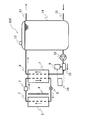
- FIG. 1 is an example of a configuration diagram of a circulation piping system according to Embodiment 1 of the present invention.
- the water heater 100 includes a hot water storage tank 14 that stores hot water (water), a gas vent valve 12 that discharges gas stored in the hot water storage tank, an air heat exchanger 1, and a blower 4 that blows air to the air heat exchanger 1.
- the compressor 3 for compressing the refrigerant, the water heat exchanger 7, the decompression means 5 for depressurizing the compressed refrigerant, the water pump 11 for feeding water, the bubble injection device 10, and the carbon dioxide supply device 8 And a control unit 24.
- the water heater 100 is provided with a refrigerant channel 2 and a water channel 6.
- a hot water supply pipe 13 and a water supply pipe 15 are connected to the hot water storage tank 14. Water is supplied from the outside to the hot water storage tank 14 through the water supply pipe 15, and the hot water stored in the hot water storage tank 14 flows out through the hot water supply pipe 13.
- carbon dioxide (CO 2 ) refrigerant flows in the refrigerant flow path 2.
- the flow direction of the refrigerant in the refrigerant flow path 2 is the arrow direction in FIG.
- the refrigerant flow path 2 is provided with an air heat exchanger 1, a compressor 3, a water heat exchanger 7, and a decompression unit 5 in this order.
- the refrigerant flowing through the refrigerant flow path 2 exchanges heat with the atmosphere supplied to the air heat exchanger 1 when the blower 4 is driven. Thereby, the refrigerant flowing through the air heat exchanger 1 absorbs heat from the atmosphere and rises in temperature, and the atmosphere supplied to the air heat exchanger 1 dissipates heat to the refrigerant and falls in temperature.
- the refrigerant that has absorbed heat from the atmosphere and has risen in temperature is supplied to the suction side of the compressor 3 and compressed.
- the refrigerant that has been compressed in the compressor 3 to a high temperature and a high pressure exchanges heat with water flowing through the water flow path 6 through the heat transfer surface of the water heat exchanger 7.
- the refrigerant that has flowed out of the water heat exchanger 7 in the refrigerant flow path 2 is decompressed by the decompression means 5, becomes a low temperature, and is supplied to the air heat exchanger 1.
- the water supplied by the water pump 11 flows through the water flow path 6.
- the direction of water flow in the water channel 6 is the direction of the arrow in FIG.
- the water flow path 6 is provided with a hot water storage tank 14, a water pump 11, a bubble injection device 10, and a water heat exchanger 7 in this order.
- the hot water storage tank 14 is provided with a gas vent valve 12.
- the bubble injection device 10 is connected to the carbon dioxide supply device 8.
- the bubble injection device 10 may be provided on the upstream (inlet) side of the water heat exchanger 7 or may be provided on the upstream side of the water pump 11.
- the water stored in the hot water storage tank 14 flows into the water heat exchanger 7 through the water flow path 6, and exchanges heat with the refrigerant supplied from the air heat exchanger 1 in the water heat exchanger 7.
- FIG. 1 shows an example of a countercurrent type water heat exchanger in which the refrigerant and water flow in opposite directions, but the present invention is not limited to this example, and the refrigerant and water flow in parallel. It may be a flow type water heat exchanger.
- the present invention is not limited to this example, and the vertically upward direction of the water heat exchanger. It may be a water heat exchanger in which water flows vertically downward.
- the water heat exchanger 7 heats water by heat exchange between the refrigerant and water.
- a plate-type heat exchanger a multi-tube heat exchanger, a double-tube heat exchanger, a microchannel heat exchanger, a boiler heat exchanger, a torsion pipe heat exchanger Can be adopted.
- the bubble injection device 10 is provided on the upstream (inlet) side of the water heat exchanger 7 and has a function of injecting bubbles into the water flowing into the water heat exchanger 7.
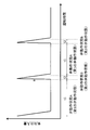
- FIG. 3 illustrates a time chart illustrating pulsed bubbles as an example of intermittently injecting bubbles in the present invention.
- the pulse bubble refers to a bubble in which the amount of bubbles injected into water has a pulse waveform.
- a pulse bubble injection device is used as an example of a bubble injection device 10 that injects pulse bubbles.
- the pulse bubble injection device will be described later.
- the installation position of the pulse bubble injection apparatus mentioned later should just be on the water flow path 6 of the upstream of the water heat exchanger 7, and is not specifically limited.
- FIG. 2 is an example of a configuration diagram showing the bubble injection device and the carbon dioxide supply device of the circulation piping system according to Embodiment 1 of the present invention.
- the pulse bubble injection device 10 b includes a gas-liquid mixing unit 23, a negative pressure forming unit 22, and a first opening / closing valve 9.
- the gas-liquid mixing unit 23, the negative pressure forming unit 22, and the first on-off valve 9 are connected in the order of the gas-liquid mixing unit 23, the negative pressure forming unit 22, and the first on-off valve 9.
- the negative pressure forming unit 22 is connected to the gas-liquid mixing unit 23, the first on-off valve 9 is connected to the negative pressure forming unit 22, and a negative pressure is formed between the gas-liquid mixing unit 23 and the first on-off valve 9. It is connected so that part 22 may intervene.
- the first opening / closing valve 9 is connected to the carbon dioxide supply device 8 and is provided between the negative pressure forming unit 22 and the carbon dioxide supply device 8.
- FIG. 6 is an example showing the bubble injection device of the circulation piping system according to Embodiment 1 of the present invention.
- 6 (a) shows a gas introduction tube
- FIG. 6 (b) shows a diffuser tube, a diffuser bulb, and a porous nozzle
- FIG. 6 (c) shows a spray nozzle
- FIG. 6 (d) shows an ejector.
- FIG. 6 (e) shows pressurized supply.
- solid arrows indicate the direction of water flow
- broken arrows indicate the direction of gas flow.
- bowl, and a porous nozzle differs.
- the gas-liquid mixing unit 23 has a gas introduction pipe (see FIG.
- the ejector is provided with a constricted portion on the flow path flowing through the water flow path 6, and the flow velocity of the water flowing through the water flow path 6 is increased at this portion.
- a decompression phenomenon usually called Bernoulli's theorem
- gas can be sucked from the gas introduction tube, and bubbles can be injected into the water flowing through the water flow path 6.
- the present invention is not limited to this example, and the water may flow in the vertical direction.
- the pressure difference between the primary side and the secondary side can be increased, and the constricted part It is possible to increase the amount of gas sucked from the gas introduction pipe by increasing the decompression phenomenon generated in the above. That is, the amount of gas suction obtained with the same power is large, and it is possible to increase the operation efficiency (energy saving).
- the gas-liquid mixing unit 23 is connected to the carbon dioxide supply device 8 through the negative pressure forming unit 22 and the first on-off valve 9. For this reason, the gas sucked in the gas-liquid mixing unit 23 is a gas having a high carbon dioxide concentration supplied from the carbon dioxide supply device 8 (details will be described later). Thus, bubbles having a high carbon dioxide concentration can be injected into the water flowing through the water flow path 6.
- a check valve may be provided between the gas-liquid mixing unit 23 and the negative pressure forming unit 22 so that the gas flow direction changes from the negative pressure forming unit 22 to the gas-liquid mixing unit 23.
- the negative pressure forming part 22 provided between the gas-liquid mixing part 23 and the first on-off valve 9 has a certain volume space.
- the first on-off valve 9 has a function of communicating or blocking the negative pressure forming unit 22 and the carbon dioxide supply device 8 by opening and closing the valve.
- a solenoid valve can be used, for example.
- the first opening / closing valve 9 is connected to the control unit 24, and the opening / closing of the valve can be controlled by the control unit 24.
- the carbon dioxide supply device 8 includes a carbon dioxide concentrating unit 18, an intake pipe 21, a second on-off valve 19, a blower pump 20, a discharge pipe 16, and a third on-off valve 17.
- the carbon dioxide supply device 8 is connected to the pulse bubble injection device 10b and has a function of supplying a gas having a high carbon dioxide concentration to the pulse bubble injection device 10b. For this reason, the carbon dioxide supply device 8 and the pulse bubble injection device 10 b can inject bubbles having a high carbon dioxide concentration into the water flowing through the water flow path 6.
- the carbon dioxide concentrating unit 18 is provided with an adsorbent that adsorbs carbon dioxide inside, and has a function of concentrating carbon dioxide by adsorption.
- an adsorbent having such a function for example, zeolite, molecular sieve, alumina, activated carbon, solid amine and the like can be used.
- a second open / close valve 19 and a blower pump 20 are connected to the carbon dioxide concentrating portion 18 via an intake pipe 21, and a third open / close valve 17 is connected via a discharge pipe 16.
- the second on-off valve 19 and the blower pump 20 need only be provided in the middle of the intake pipe 21, but are arranged so that the second on-off valve 19 is interposed between the carbon dioxide concentrating unit 18 and the blower pump 20. More preferably.
- the intake pipe 21 has a function of passing air sent from the atmosphere to the carbon dioxide concentrating unit 18 by the blower pump 20.
- the second on-off valve 19 is provided in the middle of the intake pipe 21, and has a function of opening and closing the valve to communicate or block the carbon dioxide concentrating unit 18 and the atmosphere.
- a solenoid valve can be used for the 2nd on-off valve 19, for example.
- the second opening / closing valve 19 is connected to the control unit 24, and the opening / closing of the valve can be controlled by the control unit 24.
- the 2nd on-off valve 19 should just be provided in the middle of the intake pipe 21, and is not limited to the position (between the carbon dioxide concentration part 18 and the ventilation pump 20) shown in figure.
- the discharge pipe 16 has one end connected to the carbon dioxide concentrating unit 18 and the other end open to the atmosphere.
- the discharge pipe 16 has a function of discharging the air sent to the carbon dioxide concentrating unit 18 by the blower pump 20 to the atmosphere.
- the third on-off valve 17 is provided in the middle of the discharge pipe 16, and has a function of opening and closing to connect or block the carbon dioxide concentrating unit 18 and the atmosphere. As what has such a function, a solenoid valve can be used for the 3rd on-off valve 17, for example.
- the third on-off valve 17 is connected to the control unit 24, and the control unit 24 can control the opening / closing of the valve.
- the blower pump 20 is provided in the middle of the intake pipe 21, and has a function of flowing air in the order of the intake pipe 21, the carbon dioxide concentrating unit 18, and the discharge pipe 16. In addition, you may provide the connection position of the ventilation pump 20 in the middle of the exhaust pipe 16 instead of the middle of the intake pipe 21 mentioned above.
- the blower pump 20 is connected to the control unit 24, and the control unit 24 can control power ON / OFF.
- the carbon dioxide concentrating unit 18 and the intake pipe 21 are connected at a position close to the first on-off valve 9 (shown in the vertical downward direction in the figure), and the carbon dioxide concentrating unit 18 and the exhaust pipe 16 are far from the first on-off valve 9. They are connected at a position (shown in the vertical direction in the figure). That is, the connection position between the carbon dioxide concentrating part 18 and the intake pipe 21 is closer to the first on-off valve 9 than the connection position between the carbon dioxide concentrating part 18 and the exhaust pipe 16.
- the first on-off valve 9, the second on-off valve 19, the third on-off valve 17, and the blower pump 20 are each connected to the control unit 24.
- the controller 24 controls the opening / closing of the first opening / closing valve 9, the second opening / closing valve 19, the third opening / closing valve 17, and the blower pump 20 so as to operate in conjunction with each other.
- FIG. 4 and FIG. 5 are examples of configuration diagrams for explaining the operating state of the circulation piping system according to Embodiment 1 of the present invention.
- the solid line arrows indicate the water flow direction
- the broken line arrows indicate the gas flow direction.
- FIG. 5 shows the valve operating state B.
- the open / close state of each open / close valve is indicated by o (open) and c (closed) attached to the back of the reference numeral.
- the gas in the negative pressure forming unit 22 When in the valve operation state A, the gas in the negative pressure forming unit 22 is sucked due to the pressure reducing phenomenon of the gas-liquid mixing unit 23. If this state is maintained, the gas in the negative pressure forming part 22 decreases, so the pressure in the negative pressure forming part 22 gradually decreases to a negative pressure state (a state below atmospheric pressure). At this time, the difference in internal pressure between the carbon dioxide supply device 8 and the negative pressure forming unit 22 is large.
- the first on-off valve 9 When the first on-off valve 9 is opened in this state, that is, when the valve operating state A is switched to the valve operating state B, the carbon dioxide concentrating unit 18 and the pulse bubble injection device 10b communicate with each other. A large pressure difference is instantaneously obtained between the negative pressure forming unit 22 and the negative pressure forming unit 22.
- a gas having a high carbon dioxide concentration can be supplied all at once from the carbon dioxide concentrating unit 18 (carbon dioxide supply device 8) to the pulse bubble injection device 10b (negative pressure forming unit 22).
- the gas supplied to the negative pressure forming unit 22 is instantaneously sucked by the depressurization phenomenon of the gas-liquid mixing unit 23. From this, by opening the first on-off valve 9 instantaneously, pulse bubbles can be injected into the water flowing through the water flow path 6 with a large pressure difference obtained instantaneously.
- FIG. 3 is a time chart for explaining the pulse bubbles in the first embodiment of the present invention.
- the vertical axis represents the amount of bubble injection
- the horizontal axis represents the operation time of the water heater 100.
- the control unit 24 sets the operation time t1 in the valve operation state A to 1 to 30 minutes, for example, and sets the operation time t2 in the valve operation state B to, for example, about 5 to 20 seconds.
- the one on-off valve 9, the second on-off valve 19, the third on-off valve 17 and the blower pump 20 are controlled.
- the ratio (t1 / t2) of the operation time between the valve operation state A and the valve operation state B is, for example, 3 ⁇ (t1 / t2) ⁇ 360, preferably 5 ⁇ (t1 / t2) ⁇ 180, more preferably 10 ⁇ . Control is performed by the control unit 24 so that (t1 / t2) ⁇ 40.
- the control unit 24 performs control so that the duration of the valve operating state B is 5 to 20 seconds, and the duration of the valve operating state A is longer than 3 times and shorter than 360 times of the duration of the valve operating state B.
- the duration of the valve operating state A is controlled to be longer than 5 times and shorter than 180 times the duration of the valve operating state B, more preferably the duration of the valve operating state A is the valve operating state. It is controlled to be longer than 10 times and shorter than 40 times the duration of B.
- a large pulse bubble having a bubble diameter of 1 mm or more can be injected into the water flow path 6.
- a pulse bubble with a large bubble diameter if a small bubble with a bubble diameter of 100 ⁇ m or less, called a microbubble, is attached to the heat transfer surface of the heat exchanger, the pulse bubble with a large bubble diameter and the heat transfer surface It is possible to obtain an effect that the attached microbubbles are united and peeled off from the heat transfer surface.
- the inventors of the present application observed a phenomenon in which a pulse bubble having a large bubble diameter merged with a small bubble of 100 ⁇ m or less adhering to the heat transfer surface of the heat exchanger and peeled off from the heat transfer surface.
- the water heater 100 Under the control of the control unit 24, the water heater 100 is operated in the valve operation state A, that is, the first on-off valve 9 is closed, the second on-off valve 19 and the third on-off valve 17 are opened, and the blower pump 20 is on. Started.
- the valve operation state A the flow rate of water flowing through the water flow path 6 of the water heater 100 was set to about 18 to 20 L / min.
- the volume space (volume) of the negative pressure forming unit 22 is about 100 cm 3
- the volume of the carbon dioxide concentrating unit 18 is about 150 cm 3
- the carbon dioxide concentrating unit 18 is filled with about 100 g of zeolite as a carbon dioxide adsorbent. Drove.
- valve was switched to the valve operation state B under the control of the control unit 24.
- pulse bubbles having a high carbon dioxide concentration were injected into the water flow path 6 at a stretch due to the pressure difference between the carbon dioxide concentrating unit 18 and the negative pressure forming unit 22. This state was continued for 5 seconds (t2).
- valve operation state A and the valve operation state B were repeated, and the water heater 100 was operated while injecting pulsed bubbles into the water flowing through the water flow path 6.
- the decrease in COP Coefficent of Performance
- the amount of pulse bubbles flowing into the heat exchanger can be controlled, and the effect of suppressing the decrease in heat exchange efficiency was obtained while the effect of suppressing the precipitation of scale was obtained.
- the first on-off valve 9 when the first on-off valve 9 is opened, a large pressure difference that is obtained instantaneously causes the carbon dioxide concentration unit 18 of the carbon dioxide supply device 8 to change the bubble injection device 10.
- a gas having a high carbon dioxide concentration can be supplied to the negative pressure forming unit 22 at once.
- the valve operation state A and the valve operation state B as described above, the amount of high bubbles of carbon dioxide flowing into the heat exchanger is controlled, and the decrease in heat exchange efficiency is suppressed. An adhesion suppressing effect can be obtained.
- the inventors of the present application show that when small bubbles (100 ⁇ m or less) called microbubbles flow into the heat exchanger, the microbubbles easily adhere to the heat transfer surface of the heat exchanger. Was observed.
- the microbubbles adhering to the heat transfer surface directly reduce the heat transfer area effective for heat exchange, which contributes to a decrease in heat exchange efficiency.
- the bubble to be injected is the pulse bubble described above, the bubble can flow intermittently into the water flow path 6, and the water heat exchanger 7. It is possible to control the amount of bubbles flowing into the. From this, the effect which suppresses the fall of heat exchange efficiency can be acquired, acquiring the suppression effect of scale adhesion by inject
- a large pulse bubble having a bubble diameter of 1 mm or more can be injected into the water flow path 6. Since it is possible to inject pulse bubbles having a large bubble diameter, even if the above-described microbubbles are attached to the heat transfer surface of the water heat exchanger 7, the microbubbles attached to the pulse bubble having a large bubble diameter and the heat transfer surface are attached. Therefore, the effect of peeling off the microvalve from the heat transfer surface can be obtained. That is, according to this Embodiment 1, the reduction of the heat transfer area by adhesion of microbubbles can be suppressed, and the effect which suppresses the fall of heat exchange efficiency can be heightened more.
- the carbon dioxide concentration unit 18 can supply a gas having a high carbon dioxide concentration of about 50 to 96% to the water flow path 6.
- connection position between the carbon dioxide concentrating unit 18 and the intake pipe 21 and the connection position between the carbon dioxide concentrating unit 18 and the exhaust pipe 16 are not particularly limited. However, as in the first embodiment, the carbon dioxide concentrating unit 18 is connected. More preferably, the connection position between the intake pipe 21 and the intake pipe 21 is provided closer to the first on-off valve 9 than the connection position between the carbon dioxide concentrating portion 18 and the exhaust pipe 16. By providing the intake pipe 21 and the exhaust pipe 16 in such a positional relationship, the air (atmosphere) flowing through the carbon dioxide concentrating unit 18 can flow from the side closer to the first on-off valve 9 to the side farther away.
- carbon dioxide adsorbed by the adsorbent provided inside the carbon dioxide concentrating unit 18 can be adsorbed from a position close to the first on-off valve 9.
- the amount of carbon dioxide adsorbed by the adsorbent located near the first on-off valve 9 is always greater than or equal to the amount of carbon dioxide adsorbed by the adsorbent located far from the first on-off valve 9. Can be.
- the valve operation state B since the carbon dioxide adsorbed by the adsorbent close to the first on-off valve 9 is sucked (desorbed), bubbles with a high carbon dioxide concentration are quickly converted into water flowing through the water flow path 6. Can supply.
- the blower pump 20 can be a pump with high pressure supply.
- the open / close state of each valve at this time is such that the second on-off valve 19 is open and the third on-off valve 17 is half open (between fully open and fully closed). Can be determined arbitrarily). That is, when the blower pump 20 is turned on and air is allowed to flow to the carbon dioxide concentrating unit 18, the pressure flowing through the exhaust pipe 16 may be made smaller than the pressure flowing through the intake pipe 21. At this time, the internal pressure of the carbon dioxide concentrating unit 18 can be increased to atmospheric pressure or higher.
- the internal pressure of the carbon dioxide concentrating unit 18 can be increased and the pressure difference with the negative pressure forming unit 22 can be further increased.
- the above-described valve operation state B the first on-off valve 9 is open and the second on-off valve 19 and the third on-off valve 17 are both closed. Then, it is possible to inject a pulse bubble having a steeper pulse waveform slope a. The effects obtained by flowing the pulse bubbles into the water flowing through the water flow path 6 are as described above.
- the generation rate of large pulse bubbles with a bubble diameter of 1 mm or more can be increased. For this reason, even if the above-described microbubbles adhere to the heat transfer surface of the water heat exchanger 7, the microbubbles are heated by combining the large bubble bubble and the microbubble attached to the heat transfer surface.
- the effect of peeling off from the transmission surface can be further enhanced. That is, the reduction of the heat transfer surface due to the adhesion of microbubbles can be suppressed, and the effect of suppressing the decrease in heat exchange rate can be further enhanced.
- an example of a heat pump water heater is mainly described, but an air conditioner including a water heat exchanger (that is, a refrigeration cycle including a water circuit and a refrigerant circuit connected to the water heat exchanger).
- the present invention can be applied to a circulation piping system such as an apparatus.
- a pulse bubble can be inject
- the effect of suppressing the above can be obtained.
- FIG. FIG. 7 is an example of a configuration diagram of the circulation piping system according to the second embodiment.
- an example of the circulation piping system according to the second embodiment is connected to the carbon dioxide concentrating unit 18 in the configuration of the circulation piping system according to the first embodiment, and detects the temperature of the carbon dioxide concentrating unit 18.
- a temperature detection unit 25 is provided, and the temperature detection unit 25 is connected to the control unit 24.
- ⁇ ⁇ An enthalpy change occurs when the adsorbent adsorbs and desorbs carbon dioxide.
- General adsorption is exothermic and desorption is endothermic. That is, the amount of carbon dioxide adsorbed by the adsorbent can be estimated by detecting the temperature of the carbon dioxide concentrating unit 18 in the temperature detecting unit 25.
- the valve operation state A carbon dioxide is adsorbed in the adsorbent in the carbon dioxide concentrating unit 18, and the temperature of the carbon dioxide concentrating unit 18 rises due to heat of adsorption.
- the temperature rise rate at this time is considered to depend on the adsorption rate (adsorption amount) of carbon dioxide, and as the adsorbent coverage increases and approaches the adsorption saturation amount, the temperature rise rate decreases, and when the adsorbent is saturated, the temperature rises (If the valve operating state A is continued in a state where the adsorbent is saturated, it is considered that the adsorption rate and the desorption rate become equal, and no further adsorption occurs, so the temperature gradually decreases due to natural cooling).
- the control unit 24 calculates the temperature increase rate from the temperature detected by the temperature detection unit 25 and switches from the valve operation state A to the valve operation state B during the period from when the temperature increase rate starts to decrease to zero. Good.
- valve operation state B carbon dioxide is desorbed from the adsorbent that has adsorbed carbon dioxide in the carbon dioxide concentrating unit 18, and the temperature of the carbon dioxide concentrating unit 18 is lowered by the heat of desorption.
- the temperature decrease rate at this time is considered to depend on the desorption rate (desorption amount) of carbon dioxide, and as the adsorbed carbon dioxide desorbs and approaches zero, the temperature decrease rate decreases and eventually becomes zero.
- the control unit 24 calculates the temperature decrease rate from the temperature detected by the temperature detection unit 25 and switches from the valve operation state B to the valve operation state A during the period from when the temperature decrease rate starts to decrease to zero, Good.
- the adsorption process and the desorption process can be performed without waste, and the valve operation state can be switched efficiently.
- the time of the valve operation state A and the valve operation state B can be arbitrarily designed according to the filling amount of the adsorbent, the volume of the carbon dioxide concentrating unit 18, and the volume space of the negative pressure forming unit 22.
- FIG. 12 is an example of a configuration diagram of the circulation piping system according to the second embodiment of the present invention.
- the temperature detection unit 25 a connected to the inside filled with the adsorbent in the carbon dioxide concentration unit 18 and in the vicinity of the discharge pipe 16 side, and the carbon dioxide concentration unit 18 You may connect two with the temperature detection part 25b connected to the inside filled with adsorption agent, and the vicinity of the intake pipe 21 side.
- the temperature detection unit 25a is connected to the vertically upper adsorbent
- the temperature detection unit 25b is connected to the vertically lower adsorbent.
- the temperature detectors 25a and 25b By connecting the temperature detectors 25a and 25b to such positions, the temperature at the downstream of the adsorbent in the vicinity of the discharge pipe 16 can be detected directly, so the saturation state of the adsorbent can be estimated more efficiently. It becomes possible.
- the amount of carbon dioxide adsorbed on the adsorbent located near the first on-off valve 9 is always carbon dioxide adsorbed on the adsorbent located far from the first on-off valve 9.
- the amount is greater than or equal to the amount, the heat of adsorption is generated from the adsorbent at a position close to the first on-off valve 9, and the position is farther from the first on-off valve 9 as the adsorption saturation amount is approached.
- the temperature detection unit 25b can directly detect the temperature in the upstream stage of the adsorbent, it is possible to more efficiently estimate the desorption state of carbon dioxide in the adsorbent.
- the carbon dioxide adsorbed by the adsorbent close to the first on-off valve 9 in this case, the pre-adsorbent stage
- the control unit 24 determines whether the heat of desorption at the upstream of the adsorbent is detected.
- the temperature detection unit 25a is connected to switch from the valve operating state A to the valve operating state B, and the switching from the valve operating state B to the valve operating state A is performed as described in the first embodiment.
- the time for the valve operating state A can be arbitrarily designed according to the amount of adsorbent filled, the capacity of the carbon dioxide concentrating unit 18, and the volume space of the negative pressure forming unit 22.
- FIG. FIG. 8 is an example of a configuration diagram of the circulation piping system according to the third embodiment.
- an example of the circulation piping system according to the third embodiment includes a heating unit 26 that heats the carbon dioxide concentrating unit 18 in the configuration of the circulation piping system according to the first and second embodiments.
- the heating unit 26 is connected to the control unit 24.
- the carbon dioxide concentrating unit 18 can be heated in the valve operation state B, and the desorption of carbon dioxide in the carbon dioxide concentrating unit 18 can be promoted. Become. As described in the second embodiment, when carbon dioxide is desorbed, the temperature of the adsorbent decreases. Due to this temperature decrease, the desorption rate of carbon dioxide decreases. In the third embodiment, when the valve operating state B, the heating unit 26 is used to heat the carbon dioxide concentrating unit 18 so that a decrease in the desorption rate can be suppressed, and a pulse waveform is generated in the water flowing through the water channel 6. It is possible to inject a pulse bubble having a steeper slope a. The effect obtained by flowing the pulse bubbles into the water flowing through the water flow path 6 is as described in the first embodiment.
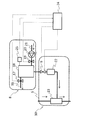
- FIG. 9 is an example of a configuration diagram of the carbon dioxide-containing water supply system according to the fourth embodiment.
- the basic configuration of the carbon dioxide supply system according to the fourth embodiment is the same as that of the circulation piping system according to the first embodiment, the second embodiment, and the third embodiment, and therefore only the differences will be described.
- an example of the carbon dioxide supply system according to the fourth embodiment is stored in the hot water storage tank 14 in the configuration of the circulation piping system according to the first embodiment, the second embodiment, and the third embodiment
- the hot water supply pipe 13 that flows out hot water (stored hot water) to the outside includes a bubble injection device 10, a carbon dioxide supply device 8, a control unit 24, and a dilution water pipe 27.
- the hot water stored in the hot water tank is operated at a temperature of about 40-90 ° C. Before it flows out, it is mixed with hot water and tap water so that it reaches the temperature required at the point of use. Outflow (supply) to an external use point.
- Use points include, for example, bathtubs, showers, washrooms, kitchens, floor heating, and the like.
- carbon dioxide can be supplied to hot water (supply water) supplied to the use point.
- the bubble injection device 10 includes, for example, a gas introduction tube for flowing a gas into the liquid, an air diffusion tube for introducing the gas by dispersing the gas into the liquid, an air diffusion ball, a porous nozzle, a gas and a liquid A spray nozzle that mixes and sprays, and an ejector that creates a mixed phase flow of gas and liquid.
- a gas introduction tube for flowing a gas into the liquid
- an air diffusion tube for introducing the gas by dispersing the gas into the liquid
- an air diffusion ball for introducing the gas by dispersing the gas into the liquid
- a porous nozzle for introducing the gas by dispersing the gas into the liquid
- a gas and a liquid A spray nozzle that mixes and sprays
- an ejector that creates a mixed phase flow of gas and liquid.
- the bubble injection device 10 may be provided on the hot water supply pipe 13, and may be upstream or downstream of the junction with the dilution water pipe 27. According to Henry's Law, the effect of the present invention is higher because the amount of carbon dioxide (gas) dissolved is greater when it is provided on the downstream side with a lower water temperature than on the upstream side with a higher water temperature. In addition, it is more convenient to install near the outflow outlets such as bathtubs, showers, washrooms, kitchens, floor heating, etc., because the operating state of the carbon dioxide supply system can be selected for each use point. high. Needless to say, the operating state (operation ON / OFF) of the carbon dioxide supply system may be selected using an external operation panel (not shown) of the carbon dioxide supply system.
- FIG. 10 is an example of a configuration diagram of a carbon dioxide-containing water supply system according to Embodiment 4 of the present invention.
- the bubble injection device 10 may be provided on the dilution water pipe 27. Since the water temperature of the tap water flowing through the dilution water pipe 27 is lower than the water temperature of the water flowing through the hot water supply pipe 13, more carbon dioxide (gas) can be dissolved according to Henry's law. For this reason, the effect of suppressing the adhesion of scale described in the first embodiment is higher.
- the configurations and operation methods of the bubble injection device 10, the carbon dioxide supply device 8, and the control unit 24 are the first embodiment, the second embodiment, and the third embodiment. It goes without saying that it should be the same.
- FIG. 11 is an example of a configuration diagram of the carbon dioxide-containing water supply system according to the fifth embodiment.
- the basic configuration of the carbon dioxide supply system according to the fifth embodiment is the same as the circulation piping system according to the first embodiment, the second embodiment, the third embodiment, and the fourth embodiment. Only the differences will be described.
- an example of the carbon dioxide supply system according to the fifth embodiment is a heating pipe in the configuration of the circulation piping system according to the first embodiment, the second embodiment, the third embodiment, and the fourth embodiment. 28, a reheating heat exchanger 29, circulation pumps 30 and 31, a recirculation circulation pipe 32, and a bathtub 33.
- water is converted into hot water (hot water) by the heat supplied by the cooling / heating cycle of the circulation piping system, the hot water boiling function for storing hot water in the hot water storage tank 14, the hot water supply function for supplying hot water to the bathtub 33, It has a chasing function for chasing the bath water of the bathtub 33.
- the hot water storage tank 14 is provided with a heating pipe 28 for supplying hot water to the reheating heat exchanger 29 and a circulation pump 30 for circulating the hot water.
- a recirculation circulation pipe 32 for reheating is connected to a reheating heat exchanger 29.
- a bubble injection device 10 for bubble injection is attached to the circulation pipe 32 for reheating.
- the attachment position of the bubble injection device 10 is not limited to this example, and the effect of the fifth embodiment can be obtained regardless of whether it is provided on the upstream side or the downstream side of the reheating heat exchanger 29. .
- the bubbles can be injected more efficiently. Is possible. In other words, more bubbles can be injected with the same power (energy saving operation).
- the bath water heater In order to raise the temperature of the bath water when the bath water in the bathtub has cooled and is no longer suitable for bathing, the bath water heater is usually provided with a reheating function.
- the bath water is heated with a heat exchanger for reheating.
- FIG. 11 an example of a countercurrent reheating heat exchanger that flows in a direction in which hot water and bath water flow in opposite directions is shown in FIG. 11, but the present invention is not limited to this example. Alternatively, it may be a co-current reheating heat exchanger in which hot water and bath water flow in parallel. Moreover, although the example in which the bath water flows from the vertically downward direction to the vertically upward direction of the reheating heat exchanger is shown in FIG. 11, the present invention is not limited to this example, and reheating heat exchange is performed. It may be a reheating heat exchanger in which the bath water flows from the vertically upward direction to the vertically downward direction of the vessel.
- the reheating heat exchanger 29 heats water by heat exchange between warm water and bath water.
- a plate heat exchanger, a multi-tube heat exchanger, a double tube heat exchanger, a microchannel heat exchanger, a boiler heat exchanger, a twisted tube heat exchanger can be used as the heat exchanger 29 for reheating.
- bubbles including carbon dioxide are injected by the bubble injection device 10 provided in the recirculation circulation pipe 32, and pulsed bubbles can be injected into the bathtub 33.
- the operations of the bubble injection device 10, the carbon dioxide supply device 8, and the control unit 24 may be operated as described in the first embodiment, the second embodiment, and the third embodiment.
- pulsed bubbles containing carbon dioxide can be supplied to the bathtub 33 by using the circulation pipe 32 for reheating during bathing, and thus the above-described effect is higher. Moreover, since pulsed bubbles containing carbon dioxide can be supplied intermittently (rhythm supply), it is considered possible to stimulate the bather's sensitivity and improve the comfort during bathing.
Landscapes
- Engineering & Computer Science (AREA)
- Chemical & Material Sciences (AREA)
- Combustion & Propulsion (AREA)
- Mechanical Engineering (AREA)
- General Engineering & Computer Science (AREA)
- Physics & Mathematics (AREA)
- Thermal Sciences (AREA)
- Heat-Pump Type And Storage Water Heaters (AREA)
- Carbon And Carbon Compounds (AREA)
Abstract
Description

図1は、本発明の実施の形態1に係る循環配管システムの構成図の一例である。給湯器100は、お湯(水)を溜める貯湯タンク14と、貯湯タンク内に貯まった気体を排出するガス抜き弁12と、空気熱交換器1と、空気熱交換器1に送風する送風機4と、冷媒を圧縮する圧縮機3と、水熱交換器7と、圧縮された冷媒を減圧させる減圧手段5と、水を送液する水ポンプ11と、気泡注入装置10と、二酸化炭素供給装置8と、制御部24とを備える。給湯器100には、冷媒流路2及び水流路6が設けられている。貯湯タンク14には、給湯配管13と給水配管15が接続されている。給水配管15を介して外部から貯湯タンク14に水が供給され、貯湯タンク14に溜められたお湯は給湯配管13を介して外部へ流出する。
図7は、本実施の形態2に係る循環配管システムの構成図の一例である。なお、本実施の形態2に係る循環配管システムの基本的な構成は、実施の形態1に係る循環配管システムと同じであるため、相違点のみ説明する。図7において、本実施の形態2に係る循環配管システムの一例は、実施の形態1に係る循環配管システムの構成において、二酸化炭素濃縮部18に接続され、二酸化炭素濃縮部18の温度を検出する温度検出部25を備え、温度検出部25は制御部24と接続されていることを特徴とする。上記のような構成を有する循環配管システムでは、二酸化炭素濃縮部18の温度を検知することにより、二酸化炭素濃縮部18内に設けられた二酸化炭素を吸着する吸着剤の吸着量を推測して、弁動作状態Aと弁動作状態Bを効率よく切換えることが可能となる。
図8は、本実施の形態3に係る循環配管システムの構成図の一例である。なお、本実施の形態3に係る循環配管システムの基本的な構成は、実施の形態1及び実施の形態2に係る循環配管システムと同じであるため、相違点のみ説明する。図8において、本実施の形態3に係る循環配管システムの一例は、実施の形態1及び実施の形態2に係る循環配管システムの構成において、二酸化炭素濃縮部18を加熱する加熱部26を備え、加熱部26は制御部24と接続されていることを特徴とする。
図9は、本実施の形態4に係る二酸化炭素含有水供給システムの構成図の一例である。なお、本実施の形態4に係る二酸化炭素供給システムの基本的な構成は、実施の形態1、実施の形態2及び実施の形態3に係る循環配管システムと同じであるため、相違点のみ説明する。図9において、本実施の形態4に係る二酸化炭素供給システムの一例は、実施の形態1、実施の形態2及び実施の形態3に係る循環配管システムの構成において、貯湯タンク14に溜められた(貯湯された)お湯を外部へ流出する給湯配管13に、気泡注入装置10、二酸化炭素供給装置8、制御部24、希釈水配管27とを備えることを特徴とする。
図11は、本実施の形態5に係る二酸化炭素含有水供給システムの構成図の一例である。なお、本実施の形態5に係る二酸化炭素供給システムの基本的な構成は、実施の形態1、実施の形態2、実施の形態3及び実施の形態4に係る循環配管システムと同じであるため、相違点のみ説明する。図11において、本実施の形態5に係る二酸化炭素供給システムの一例は、実施の形態1、実施の形態2、実施の形態3、及び実施の形態4に係る循環配管システムの構成において、加熱配管28、追い焚き用熱交換器29、循環ポンプ30、31、追い焚き用循環配管32、浴槽33を備えることを特徴とする。
Claims (10)
- 第1の装置と第2の装置との間で水を循環させる循環配管と、
前記水へ気泡を注入する気泡注入装置と、
前記気泡注入装置に接続され、前記気泡を生じさせるために二酸化炭素を供給する二酸化炭素供給装置と、
前記二酸化炭素を含む前記気泡が前記循環配管を循環する前記水へ断続的に注入されるよう前記気泡注入装置及び前記二酸化炭素供給装置を制御する制御部とを備える
循環配管システム。 - 前記気泡注入装置は、
前記二酸化炭素供給装置に接続され、供給された前記二酸化炭素に対して負圧を形成する負圧形成部と、
前記負圧を介して前記負圧形成部に取り込まれた前記二酸化炭素を前記水に混合する気液混合部と、
前記負圧形成部と前記二酸化炭素供給装置との間に接続され、前記制御部によって開閉が制御される第一開閉弁とを備える
請求項1に記載の循環配管システム。 - 前記二酸化炭素供給装置は、
大気中の空気を流す送風ポンプと
供給する前記二酸化炭素として、前記空気に含まれる二酸化炭素を吸着する二酸化炭素濃縮部と、
前記二酸化炭素濃縮部と前記送風ポンプとの間に接続され、前記制御部によって開閉が制御される第二開閉弁と、
前記二酸化炭素濃縮部へ流した前記空気を排出するための排出管と、
前記二酸化炭素濃縮部と前記排出管との間に接続され、前記制御部によって開閉が制御される第三開閉弁とを備える
請求項1または2に記載の循環配管システム。 - 前記制御部は、前記第一開閉弁が閉じていると共に前記第二開閉弁及び前記第三開閉弁が開いている第1の弁動作状態と前記第一開閉弁が開いていると共に前記第二開閉弁及び前記第三開閉弁が閉じている第2の弁動作状態とを交互に繰り返す制御を行う
請求項3に記載の循環配管システム。 - 前記制御部は、前記第2の弁動作状態の継続時間が5~20秒であり、前記第1の弁動作状態の継続時間が前記第2の弁動作状態の継続時間の3倍より長くかつ360倍より短くなる制御を行う
請求項4に記載の循環配管システム。 - 前記二酸化炭素濃縮部の温度を検出する温度検出部を備え、
前記制御部は、前記温度検出部が検出した前記温度に基づいて前記第三開閉弁の開閉を制御する
請求項3に記載の循環配管システム。 - 請求項1~6のいずれか1項に記載の循環配管システムを備え、
前記第1の装置は、前記水を加熱する熱交換器であり、
前記第2の装置は、前記水を貯留する貯湯タンクであり、
前記貯湯タンクに貯留された前記水を給湯する給湯配管を備える
二酸化炭素含有水供給システム。 - 前記二酸化炭素供給装置は、前記給湯配管により給湯される前記水に前記二酸化炭素を供給する
請求項7に記載の二酸化炭素含有水供給システム。 - 請求項1に記載の循環配管システムと、
水を供給する水配管とを備え、
前記気泡注入装置は前記水配管に接続してあり、前記二酸化炭素を含む前記気泡を前記水配管に注入する
二酸化炭素含有水供給システム。 - 請求項1に記載の循環配管システムと、
浴槽とを備え、
前記気泡注入装置は前記浴槽に接続してあり、前記二酸化炭素を含む前記気泡を前記浴槽に注入する
二酸化炭素含有水供給システム。
Priority Applications (2)
| Application Number | Priority Date | Filing Date | Title |
|---|---|---|---|
| EP16889927.6A EP3415836A4 (en) | 2016-02-12 | 2016-11-29 | CIRCULATING PIPING SYSTEM AND SYSTEM FOR DELIVERING WATER WITH CARBON DIOXIDE |
| JP2017525418A JP6192881B1 (ja) | 2016-02-12 | 2016-11-29 | 循環配管システム及び二酸化炭素含有水供給システム |
Applications Claiming Priority (2)
| Application Number | Priority Date | Filing Date | Title |
|---|---|---|---|
| JP2016-024853 | 2016-02-12 | ||
| JP2016024853 | 2016-02-12 |
Publications (1)
| Publication Number | Publication Date |
|---|---|
| WO2017138226A1 true WO2017138226A1 (ja) | 2017-08-17 |
Family
ID=59563224
Family Applications (1)
| Application Number | Title | Priority Date | Filing Date |
|---|---|---|---|
| PCT/JP2016/085332 Ceased WO2017138226A1 (ja) | 2016-02-12 | 2016-11-29 | 循環配管システム及び二酸化炭素含有水供給システム |
Country Status (3)
| Country | Link |
|---|---|
| EP (1) | EP3415836A4 (ja) |
| JP (1) | JP6192881B1 (ja) |
| WO (1) | WO2017138226A1 (ja) |
Cited By (7)
| Publication number | Priority date | Publication date | Assignee | Title |
|---|---|---|---|---|
| CN108202055A (zh) * | 2018-02-13 | 2018-06-26 | 鞍钢股份有限公司 | 一种脱硫塔上段和制酸尾气碱洗塔的清洗方法 |
| CN113244737A (zh) * | 2021-04-08 | 2021-08-13 | 刘小丽 | 一种用于空气污染治理的吸附装置 |
| CN114380419A (zh) * | 2021-12-30 | 2022-04-22 | 金澳科技(湖北)化工有限公司 | 一种利用甲醇制氢尾气在线清除冷却器水垢的系统及方法 |
| JP7301255B1 (ja) | 2022-07-15 | 2023-06-30 | 三菱電機株式会社 | 二酸化炭素回収システム |
| WO2025197613A1 (ja) * | 2024-03-19 | 2025-09-25 | 株式会社明電舎 | オゾン水の生成装置 |
| JP2025143814A (ja) * | 2024-03-19 | 2025-10-02 | 株式会社明電舎 | オゾン水の生成装置 |
| JP2025143816A (ja) * | 2024-03-19 | 2025-10-02 | 株式会社明電舎 | オゾン水の生成装置 |
Families Citing this family (1)
| Publication number | Priority date | Publication date | Assignee | Title |
|---|---|---|---|---|
| JP2022061817A (ja) * | 2020-10-07 | 2022-04-19 | 三菱電機株式会社 | 給湯装置 |
Citations (13)
| Publication number | Priority date | Publication date | Assignee | Title |
|---|---|---|---|---|
| JPH04241860A (ja) * | 1991-01-14 | 1992-08-28 | Matsushita Electric Works Ltd | 微細気泡発生装置 |
| JPH0576718A (ja) * | 1991-09-25 | 1993-03-30 | Matsushita Electric Works Ltd | 吸着分離装置 |
| JPH05200091A (ja) * | 1992-01-27 | 1993-08-10 | Matsushita Electric Works Ltd | 炭酸泉製造装置 |
| JPH0671149A (ja) * | 1992-08-28 | 1994-03-15 | Matsushita Electric Works Ltd | 飲料水製造装置 |
| JPH06253682A (ja) * | 1993-02-26 | 1994-09-13 | Kanebo Ltd | 植物育成ハウス |
| JPH06307712A (ja) * | 1993-04-27 | 1994-11-01 | Matsushita Electric Works Ltd | 炭酸泉製造装置 |
| JP2009028579A (ja) * | 2007-07-24 | 2009-02-12 | Nishida Techno Firm Kk | 気泡発生装置 |
| JP2010078239A (ja) * | 2008-09-26 | 2010-04-08 | Tokyo Electric Power Co Inc:The | 給湯装置およびスケール析出防止方法 |
| WO2010067454A1 (ja) * | 2008-12-12 | 2010-06-17 | 三菱電機株式会社 | 給湯方法および給湯装置 |
| JP2012055845A (ja) * | 2010-09-10 | 2012-03-22 | Ebara Kogyo Senjo Kk | 水道水配管の洗浄方法および装置 |
| JP2014069097A (ja) * | 2012-09-27 | 2014-04-21 | Chubu Electric Power Co Inc | 熱交換器における海生物の除去方法 |
| JP2014073461A (ja) * | 2012-10-04 | 2014-04-24 | Metawater Co Ltd | 混合ガスの精製方法及び精製装置 |
| WO2015052840A1 (ja) * | 2013-10-11 | 2015-04-16 | 三菱電機株式会社 | 水処理装置及び給湯装置 |
Family Cites Families (2)
| Publication number | Priority date | Publication date | Assignee | Title |
|---|---|---|---|---|
| JPH06154280A (ja) * | 1992-11-27 | 1994-06-03 | Matsushita Electric Works Ltd | 炭酸泉バス |
| JP2010223525A (ja) * | 2009-03-25 | 2010-10-07 | Osaka Gas Co Ltd | 熱交換器の配管内に付着したスケールの除去方法および除去装置 |
-
2016
- 2016-11-29 WO PCT/JP2016/085332 patent/WO2017138226A1/ja not_active Ceased
- 2016-11-29 JP JP2017525418A patent/JP6192881B1/ja not_active Expired - Fee Related
- 2016-11-29 EP EP16889927.6A patent/EP3415836A4/en not_active Withdrawn
Patent Citations (13)
| Publication number | Priority date | Publication date | Assignee | Title |
|---|---|---|---|---|
| JPH04241860A (ja) * | 1991-01-14 | 1992-08-28 | Matsushita Electric Works Ltd | 微細気泡発生装置 |
| JPH0576718A (ja) * | 1991-09-25 | 1993-03-30 | Matsushita Electric Works Ltd | 吸着分離装置 |
| JPH05200091A (ja) * | 1992-01-27 | 1993-08-10 | Matsushita Electric Works Ltd | 炭酸泉製造装置 |
| JPH0671149A (ja) * | 1992-08-28 | 1994-03-15 | Matsushita Electric Works Ltd | 飲料水製造装置 |
| JPH06253682A (ja) * | 1993-02-26 | 1994-09-13 | Kanebo Ltd | 植物育成ハウス |
| JPH06307712A (ja) * | 1993-04-27 | 1994-11-01 | Matsushita Electric Works Ltd | 炭酸泉製造装置 |
| JP2009028579A (ja) * | 2007-07-24 | 2009-02-12 | Nishida Techno Firm Kk | 気泡発生装置 |
| JP2010078239A (ja) * | 2008-09-26 | 2010-04-08 | Tokyo Electric Power Co Inc:The | 給湯装置およびスケール析出防止方法 |
| WO2010067454A1 (ja) * | 2008-12-12 | 2010-06-17 | 三菱電機株式会社 | 給湯方法および給湯装置 |
| JP2012055845A (ja) * | 2010-09-10 | 2012-03-22 | Ebara Kogyo Senjo Kk | 水道水配管の洗浄方法および装置 |
| JP2014069097A (ja) * | 2012-09-27 | 2014-04-21 | Chubu Electric Power Co Inc | 熱交換器における海生物の除去方法 |
| JP2014073461A (ja) * | 2012-10-04 | 2014-04-24 | Metawater Co Ltd | 混合ガスの精製方法及び精製装置 |
| WO2015052840A1 (ja) * | 2013-10-11 | 2015-04-16 | 三菱電機株式会社 | 水処理装置及び給湯装置 |
Non-Patent Citations (1)
| Title |
|---|
| See also references of EP3415836A4 * |
Cited By (9)
| Publication number | Priority date | Publication date | Assignee | Title |
|---|---|---|---|---|
| CN108202055A (zh) * | 2018-02-13 | 2018-06-26 | 鞍钢股份有限公司 | 一种脱硫塔上段和制酸尾气碱洗塔的清洗方法 |
| CN113244737A (zh) * | 2021-04-08 | 2021-08-13 | 刘小丽 | 一种用于空气污染治理的吸附装置 |
| CN114380419A (zh) * | 2021-12-30 | 2022-04-22 | 金澳科技(湖北)化工有限公司 | 一种利用甲醇制氢尾气在线清除冷却器水垢的系统及方法 |
| JP7301255B1 (ja) | 2022-07-15 | 2023-06-30 | 三菱電機株式会社 | 二酸化炭素回収システム |
| WO2024013971A1 (ja) * | 2022-07-15 | 2024-01-18 | 三菱電機株式会社 | 二酸化炭素回収システム |
| WO2025197613A1 (ja) * | 2024-03-19 | 2025-09-25 | 株式会社明電舎 | オゾン水の生成装置 |
| JP2025143814A (ja) * | 2024-03-19 | 2025-10-02 | 株式会社明電舎 | オゾン水の生成装置 |
| JP2025143816A (ja) * | 2024-03-19 | 2025-10-02 | 株式会社明電舎 | オゾン水の生成装置 |
| JP7798126B2 (ja) | 2024-03-19 | 2026-01-14 | 株式会社明電舎 | オゾン水の生成装置 |
Also Published As
| Publication number | Publication date |
|---|---|
| EP3415836A1 (en) | 2018-12-19 |
| JPWO2017138226A1 (ja) | 2018-02-15 |
| JP6192881B1 (ja) | 2017-09-06 |
| EP3415836A4 (en) | 2019-02-27 |
Similar Documents
| Publication | Publication Date | Title |
|---|---|---|
| JP6192881B1 (ja) | 循環配管システム及び二酸化炭素含有水供給システム | |
| CN113041866B (zh) | 微气泡发生装置和热水器 | |
| JP5197762B2 (ja) | 給湯方法および給湯装置 | |
| WO2018033144A1 (zh) | 热水器及其控制方法 | |
| CN102047046A (zh) | 热泵式热水供给装置及热水的灭菌方法 | |
| CN113041924B (zh) | 微气泡发生装置和热水器 | |
| WO2018010684A1 (zh) | 热水器系统及其控制方法 | |
| CN207335147U (zh) | 热水器 | |
| WO2007135843A1 (ja) | 給湯装置 | |
| JP2009186092A (ja) | 風呂給湯装置 | |
| CN219846095U (zh) | 一种多功能饮水机 | |
| CN114111046B (zh) | 一种热水器的微气泡发生装置及控制方法 | |
| JP2010190466A (ja) | 給湯装置 | |
| JP5381731B2 (ja) | 浴槽洗浄装置およびこれを備えた追焚き機能付き給湯機 | |
| JP4767753B2 (ja) | 微細気泡発生装置、及び風呂用給湯装置 | |
| JP5361981B2 (ja) | 貯湯式給湯器 | |
| JP2009236413A (ja) | 浴槽給湯機能付き給湯機 | |
| JP2009293903A (ja) | 貯湯式給湯機 | |
| JP2011145000A (ja) | 貯湯式給湯機 | |
| CN207596534U (zh) | 气泡水制作装置 | |
| JP2012189285A (ja) | 貯湯式給湯機 | |
| JP5153398B2 (ja) | 浴槽給湯機能付き給湯機 | |
| JP5157196B2 (ja) | 貯湯式給湯機 | |
| JP5141412B2 (ja) | 浴槽給湯機能付き給湯機 | |
| JP2019138505A (ja) | 給湯機 |
Legal Events
| Date | Code | Title | Description |
|---|---|---|---|
| ENP | Entry into the national phase |
Ref document number: 2017525418 Country of ref document: JP Kind code of ref document: A |
|
| 121 | Ep: the epo has been informed by wipo that ep was designated in this application |
Ref document number: 16889927 Country of ref document: EP Kind code of ref document: A1 |
|
| NENP | Non-entry into the national phase |
Ref country code: DE |
|
| WWE | Wipo information: entry into national phase |
Ref document number: 2016889927 Country of ref document: EP |
|
| ENP | Entry into the national phase |
Ref document number: 2016889927 Country of ref document: EP Effective date: 20180912 |