WO2017138322A1 - プレート式熱交換器、およびそれを備えたヒートポンプ式暖房給湯システム - Google Patents
プレート式熱交換器、およびそれを備えたヒートポンプ式暖房給湯システム Download PDFInfo
- Publication number
- WO2017138322A1 WO2017138322A1 PCT/JP2017/001808 JP2017001808W WO2017138322A1 WO 2017138322 A1 WO2017138322 A1 WO 2017138322A1 JP 2017001808 W JP2017001808 W JP 2017001808W WO 2017138322 A1 WO2017138322 A1 WO 2017138322A1
- Authority
- WO
- WIPO (PCT)
- Prior art keywords
- heat transfer
- plate
- fluid
- transfer plate
- heat exchanger
- Prior art date
- Legal status (The legal status is an assumption and is not a legal conclusion. Google has not performed a legal analysis and makes no representation as to the accuracy of the status listed.)
- Ceased
Links
Images


Classifications
-
- F—MECHANICAL ENGINEERING; LIGHTING; HEATING; WEAPONS; BLASTING
- F28—HEAT EXCHANGE IN GENERAL
- F28D—HEAT-EXCHANGE APPARATUS, NOT PROVIDED FOR IN ANOTHER SUBCLASS, IN WHICH THE HEAT-EXCHANGE MEDIA DO NOT COME INTO DIRECT CONTACT
- F28D9/00—Heat-exchange apparatus having stationary plate-like or laminated conduit assemblies for both heat-exchange media, the media being in contact with different sides of a conduit wall
- F28D9/02—Heat-exchange apparatus having stationary plate-like or laminated conduit assemblies for both heat-exchange media, the media being in contact with different sides of a conduit wall the heat-exchange media travelling at an angle to one another
-
- F—MECHANICAL ENGINEERING; LIGHTING; HEATING; WEAPONS; BLASTING
- F28—HEAT EXCHANGE IN GENERAL
- F28D—HEAT-EXCHANGE APPARATUS, NOT PROVIDED FOR IN ANOTHER SUBCLASS, IN WHICH THE HEAT-EXCHANGE MEDIA DO NOT COME INTO DIRECT CONTACT
- F28D9/00—Heat-exchange apparatus having stationary plate-like or laminated conduit assemblies for both heat-exchange media, the media being in contact with different sides of a conduit wall
- F28D9/0031—Heat-exchange apparatus having stationary plate-like or laminated conduit assemblies for both heat-exchange media, the media being in contact with different sides of a conduit wall the conduits for one heat-exchange medium being formed by paired plates touching each other
- F28D9/0043—Heat-exchange apparatus having stationary plate-like or laminated conduit assemblies for both heat-exchange media, the media being in contact with different sides of a conduit wall the conduits for one heat-exchange medium being formed by paired plates touching each other the plates having openings therein for circulation of at least one heat-exchange medium from one conduit to another
- F28D9/005—Heat-exchange apparatus having stationary plate-like or laminated conduit assemblies for both heat-exchange media, the media being in contact with different sides of a conduit wall the conduits for one heat-exchange medium being formed by paired plates touching each other the plates having openings therein for circulation of at least one heat-exchange medium from one conduit to another the plates having openings therein for both heat-exchange media
-
- F—MECHANICAL ENGINEERING; LIGHTING; HEATING; WEAPONS; BLASTING
- F28—HEAT EXCHANGE IN GENERAL
- F28F—DETAILS OF HEAT-EXCHANGE AND HEAT-TRANSFER APPARATUS, OF GENERAL APPLICATION
- F28F3/00—Plate-like or laminated elements; Assemblies of plate-like or laminated elements
- F28F3/02—Elements or assemblies thereof with means for increasing heat-transfer area, e.g. with fins, with recesses, with corrugations
- F28F3/022—Elements or assemblies thereof with means for increasing heat-transfer area, e.g. with fins, with recesses, with corrugations the means being wires or pins
-
- F—MECHANICAL ENGINEERING; LIGHTING; HEATING; WEAPONS; BLASTING
- F28—HEAT EXCHANGE IN GENERAL
- F28F—DETAILS OF HEAT-EXCHANGE AND HEAT-TRANSFER APPARATUS, OF GENERAL APPLICATION
- F28F3/00—Plate-like or laminated elements; Assemblies of plate-like or laminated elements
- F28F3/02—Elements or assemblies thereof with means for increasing heat-transfer area, e.g. with fins, with recesses, with corrugations
- F28F3/025—Elements or assemblies thereof with means for increasing heat-transfer area, e.g. with fins, with recesses, with corrugations the means being corrugated, plate-like elements
- F28F3/027—Elements or assemblies thereof with means for increasing heat-transfer area, e.g. with fins, with recesses, with corrugations the means being corrugated, plate-like elements with openings, e.g. louvered corrugated fins; Assemblies of corrugated strips
-
- F—MECHANICAL ENGINEERING; LIGHTING; HEATING; WEAPONS; BLASTING
- F28—HEAT EXCHANGE IN GENERAL
- F28F—DETAILS OF HEAT-EXCHANGE AND HEAT-TRANSFER APPARATUS, OF GENERAL APPLICATION
- F28F3/00—Plate-like or laminated elements; Assemblies of plate-like or laminated elements
- F28F3/02—Elements or assemblies thereof with means for increasing heat-transfer area, e.g. with fins, with recesses, with corrugations
- F28F3/04—Elements or assemblies thereof with means for increasing heat-transfer area, e.g. with fins, with recesses, with corrugations the means being integral with the element
- F28F3/042—Elements or assemblies thereof with means for increasing heat-transfer area, e.g. with fins, with recesses, with corrugations the means being integral with the element in the form of local deformations of the element
- F28F3/044—Elements or assemblies thereof with means for increasing heat-transfer area, e.g. with fins, with recesses, with corrugations the means being integral with the element in the form of local deformations of the element the deformations being pontual, e.g. dimples
-
- F—MECHANICAL ENGINEERING; LIGHTING; HEATING; WEAPONS; BLASTING
- F28—HEAT EXCHANGE IN GENERAL
- F28F—DETAILS OF HEAT-EXCHANGE AND HEAT-TRANSFER APPARATUS, OF GENERAL APPLICATION
- F28F3/00—Plate-like or laminated elements; Assemblies of plate-like or laminated elements
- F28F3/02—Elements or assemblies thereof with means for increasing heat-transfer area, e.g. with fins, with recesses, with corrugations
- F28F3/04—Elements or assemblies thereof with means for increasing heat-transfer area, e.g. with fins, with recesses, with corrugations the means being integral with the element
- F28F3/042—Elements or assemblies thereof with means for increasing heat-transfer area, e.g. with fins, with recesses, with corrugations the means being integral with the element in the form of local deformations of the element
- F28F3/046—Elements or assemblies thereof with means for increasing heat-transfer area, e.g. with fins, with recesses, with corrugations the means being integral with the element in the form of local deformations of the element the deformations being linear, e.g. corrugations
-
- F—MECHANICAL ENGINEERING; LIGHTING; HEATING; WEAPONS; BLASTING
- F28—HEAT EXCHANGE IN GENERAL
- F28F—DETAILS OF HEAT-EXCHANGE AND HEAT-TRANSFER APPARATUS, OF GENERAL APPLICATION
- F28F3/00—Plate-like or laminated elements; Assemblies of plate-like or laminated elements
- F28F3/02—Elements or assemblies thereof with means for increasing heat-transfer area, e.g. with fins, with recesses, with corrugations
- F28F3/04—Elements or assemblies thereof with means for increasing heat-transfer area, e.g. with fins, with recesses, with corrugations the means being integral with the element
- F28F3/048—Elements or assemblies thereof with means for increasing heat-transfer area, e.g. with fins, with recesses, with corrugations the means being integral with the element in the form of ribs integral with the element or local variations in thickness of the element, e.g. grooves, microchannels
-
- F—MECHANICAL ENGINEERING; LIGHTING; HEATING; WEAPONS; BLASTING
- F28—HEAT EXCHANGE IN GENERAL
- F28F—DETAILS OF HEAT-EXCHANGE AND HEAT-TRANSFER APPARATUS, OF GENERAL APPLICATION
- F28F3/00—Plate-like or laminated elements; Assemblies of plate-like or laminated elements
- F28F3/02—Elements or assemblies thereof with means for increasing heat-transfer area, e.g. with fins, with recesses, with corrugations
- F28F3/06—Elements or assemblies thereof with means for increasing heat-transfer area, e.g. with fins, with recesses, with corrugations the means being attachable to the element
-
- F—MECHANICAL ENGINEERING; LIGHTING; HEATING; WEAPONS; BLASTING
- F28—HEAT EXCHANGE IN GENERAL
- F28F—DETAILS OF HEAT-EXCHANGE AND HEAT-TRANSFER APPARATUS, OF GENERAL APPLICATION
- F28F2225/00—Reinforcing means
- F28F2225/04—Reinforcing means for conduits
-
- F—MECHANICAL ENGINEERING; LIGHTING; HEATING; WEAPONS; BLASTING
- F28—HEAT EXCHANGE IN GENERAL
- F28F—DETAILS OF HEAT-EXCHANGE AND HEAT-TRANSFER APPARATUS, OF GENERAL APPLICATION
- F28F2240/00—Spacing means
-
- F—MECHANICAL ENGINEERING; LIGHTING; HEATING; WEAPONS; BLASTING
- F28—HEAT EXCHANGE IN GENERAL
- F28F—DETAILS OF HEAT-EXCHANGE AND HEAT-TRANSFER APPARATUS, OF GENERAL APPLICATION
- F28F3/00—Plate-like or laminated elements; Assemblies of plate-like or laminated elements
- F28F3/02—Elements or assemblies thereof with means for increasing heat-transfer area, e.g. with fins, with recesses, with corrugations
- F28F3/025—Elements or assemblies thereof with means for increasing heat-transfer area, e.g. with fins, with recesses, with corrugations the means being corrugated, plate-like elements
Definitions
- the present invention relates to an inner fin type plate heat exchanger in which a plurality of heat transfer plates and inner fins are alternately stacked, and a heat pump type heating and hot water supply system including the same.
- a plate-type plate in which a plurality of rectangular metal plates with passage holes serving as fluid inlets and outlets provided at four corners and metal concave and convex inner fins having substantially the same outer shape are alternately stacked.
- Patent Document 1 a plate-type plate in which a plurality of rectangular metal plates with passage holes serving as fluid inlets and outlets provided at four corners and metal concave and convex inner fins having substantially the same outer shape are alternately stacked.
- the plate-type heat exchanger described in Patent Document 1 can ensure pressure resistance, simplify the container structure, reduce the size, and simplify the manufacturing process. By direct flow design and adjustment of the fin arrangement direction, It improves the internal fluid flow and obtains sufficient thermal efficiency.
- the conventional plate heat exchanger described in Patent Document 1 has a problem in terms of pressure loss because it is difficult for the fluid to flow uniformly through the inside unless a large flow resistance is applied to the inner fin portion. Further, since the header portion does not have an effective heat transfer area, there is a problem in terms of heat transfer performance. Moreover, there are many parts in the header part, and there is a problem in terms of cost.
- the present invention has been made in order to solve the above-described problems, and is a plate type heat exchange capable of reducing costs while improving pressure loss and heat transfer performance to improve heat exchange performance. It is an object of the present invention to provide a heater and a heat pump type heating and hot water supply system including the same.
- the plate-type heat exchanger according to the present invention has a rectangular plate shape, and has a passage hole that is an inlet for the first fluid on one side in the left-right direction when viewed from the front.
- a passage hole that is an outlet of the first fluid is formed on the other side of the direction, and an adjacent hole that is an inlet of the second fluid is formed on one or the other side, and the adjacent hole of the second fluid is formed.
- An adjacent hole that is an inlet for the first fluid is formed on one side of the first side, and an adjacent hole that is an outlet for the first fluid is formed on the other side in the left-right direction when viewed from the front.
- a passage hole which is an inlet for the second fluid is formed in the side portion, and the side portion opposite to the side portion where the passage hole for the second fluid is formed.
- a second heat transfer plate in which a passage hole which is an outlet of the second fluid is formed in the part, and a plurality of the first heat transfer plate and the second heat transfer plate are alternately stacked, A first flow path in which the first fluid flows from the inlet to the outlet in the left-right direction when viewed from the front, and a second flow channel from the inlet of the second fluid to the outlet in the left-to-right direction.
- Two flow paths are alternately formed in the stacking direction between the first heat transfer plate and the second heat transfer plate, and the second fluid flows in the first flow path and the second flow path.
- a plate type heat exchanger for exchanging heat with a fluid having an inner fin between the first heat transfer plate and the second heat transfer plate, or the first heat transfer plate and the first heat transfer plate
- the two heat transfer plates have corrugated heat transfer surfaces,
- a peripheral wall is provided in the direction of the front, a flange is provided on the front side of the peripheral wall, and the flange provided on the first heat transfer plate or the second heat transfer plate is adjacent to the first heat transfer plate.
- the first fluid that flows in from the inlet of the first fluid or the second fluid that flows in from the inlet of the second fluid spreads in the vertical direction when viewed from the front, and the side far from the adjacent hole is A bypass passage that passes through and flows into the inner fin or the corrugated heat transfer surface, and flows directly toward the inner fin or the corrugated heat transfer surface without passing through the bypass passage.
- the main channel, A flat space is formed on the entire circumference of the adjacent hole, and the main flow path and the bypass are formed in the space between the peripheral wall and the inner fin or the corrugated heat transfer surface. The first fluid or the second fluid that has flowed through the flow path merges.
- the plate heat exchanger there is a bypass channel in which the first fluid flowing in from the inlet of the first fluid or the second fluid flowing in from the inlet of the second fluid flows in the vertical direction.
- the first fluid and the second fluid flow in the left-right direction while spreading in the up-down direction. Therefore, in-plane distribution uniformity of the first heat transfer plate and the second heat transfer plate can be improved, the heat transfer area of the header portion can be increased, and occurrence of stagnation of in-plane flow can be prevented. Can do.
- the bypass channel by providing the bypass channel, the channel cross-sectional area in the vicinity of the in-plane inlet / outlet of the heat transfer plate is increased, so that the entire pressure loss can be reduced. Further, the structure can be simplified and the cost can be reduced.
- FIG. 6B is a sectional view taken along line AA in FIG. 6A.
- FIG. 6B is a sectional view taken along line BB in FIG. 6A. It is CC sectional drawing of FIG. 6A.
- FIG. 6B is a DD cross-sectional view of FIG. 6A. It is EE sectional drawing of FIG. 6A.
- 6B is a sectional view taken along line FF in FIG. 6A. It is a front view which shows the state which laminated
- FIG. 11B is an enlarged front view and rear view of the GG portion of FIG. 11A.
- FIG. 11B is an enlarged front view of the HH portion of FIG. 11A.
- FIG. 12B is an enlarged front view of the KK portion in FIG. 12A. It is the front view which expanded the header part periphery of the heat exchanger plate of the plate type heat exchanger which concerns on Embodiment 11 of this invention. It is the front view which expanded the JJ part of FIG. 13A. It is the schematic which shows the structure of the heat pump type heating hot-water supply system which concerns on Embodiment 12 of this invention.
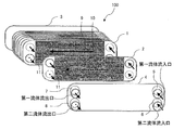
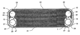
- FIG. 1A is an exploded perspective view of plate heat exchanger 100 according to Embodiment 1 of the present invention
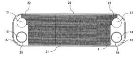
- FIG. 1B is a first heat transfer of plate heat exchanger 100 according to Embodiment 1 of the present invention. It is a front view which shows the state which laminated
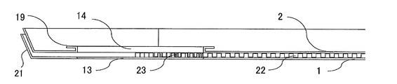
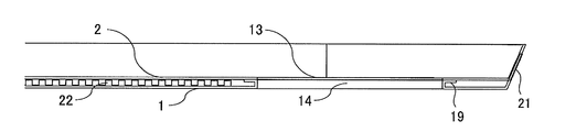
- FIG. 1F is a schematic side view showing a fluid inflow passage of plate heat exchanger 100 according to Embodiment 1 of the present invention
- FIG. 1F is a diagram of plate heat exchanger 100 according to Embodiment 1 of the present invention.
- One heat transfer plate 1 and second heat transfer plate 2 FIG. 1G is a schematic side view illustrating a stacked state
- FIG. 1G is a schematic diagram illustrating an example of a mold of the inner fin 11 of the plate heat exchanger 100 according to Embodiment 1 of the present invention.
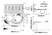
- FIG. Study on influence of improvement in in-plane velocity distribution and distribution performance by gap between peripheral wall 18 of second adjacent hole 15 and inner fin 11 of second heat transfer plate 2 of plate heat exchanger 100 according to Embodiment 1 of the present invention.
- FIG. 1D shows a schematic side view of the first adjacent hole 14 of the first heat transfer plate 1 and will be described based on this.
- the second adjacent hole 15 of the first heat transfer plate 1 the second heat transfer Since the first adjacent hole 14 and the second adjacent hole 15 of the plate 2 have substantially the same configuration, the illustration is omitted.
- 1E shows a schematic side view of the first fluid inflow passage, but the first fluid outflow passage, the second fluid inflow passage, and the outflow passage have substantially the same configuration and are not shown. .
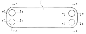
- FIG. 2 although the front schematic diagram of the right side part of the 2nd heat transfer plate 2 is shown, the left side part of the 2nd heat transfer plate 2 and the left-right direction of the 1st heat transfer plate 1 are shown. Since the side portion of this is substantially the same configuration, the illustration is omitted.
- the plate heat exchanger 100 is an inner fin type, and a plurality of first heat transfer plates 1, inner fins 11, and second heat transfer plates 2 are alternately stacked as shown in FIG. 1A. ing. Further, the first reinforcing side plate 3 and the second reinforcing side plate 4 are laminated on the outermost surface, the second reinforcing side plate 4 on the outermost surface, and the first reinforcing side plate 3 on the rearmost surface. , Respectively.
- the first heat transfer plate 1 and the second heat transfer plate 2 are collectively referred to as a heat transfer plate
- the first reinforcement side plate 3 and the second reinforcement side plate 4 are collectively referred to as a side plate.
- the first heat transfer plate 1 has a rounded rectangular plate shape, and an outer wall 21 protruding in the thickness direction is provided on the outer periphery.
- circular holes serving as fluid inflow ports or outflow ports are formed at the four corners on the lateral sides.
- a first passage hole 12 serving as a first fluid inflow port is located in the upper right
- a second passage hole 13 serving as a first fluid outflow port is located in the upper left
- a second fluid inflow port is located in the lower right.
- a first adjacent hole 14 is formed
- a second adjacent hole 15 serving as an outlet for the second fluid is formed at the lower left.
- the 1st header part 16 is provided in the one side part of the left-right direction
- the 2nd header part 27 is each provided in the other side part.
- the first passage hole 12 and the second passage hole 13 are collectively referred to as a passage hole
- the first adjacent hole 14 and the second adjacent hole 15 are collectively referred to as an adjacent hole
- the first header portion 16 and the second The two header portions 27 are collectively referred to as a header portion.
- a peripheral wall 17 is provided in the thickness direction on the peripheral edge 14 a of the first adjacent hole 14, and a flange 19 is provided on the front side of the peripheral wall 17 toward the outside of the peripheral wall 17.
- a peripheral wall 18 is provided in the thickness direction on the peripheral edge 15 a of the second adjacent hole 15, and a flange 20 is provided on the front side of the peripheral wall 18 toward the outside of the peripheral wall 18.
- the inner fin 11 has a rectangular plate shape as shown in FIG. 1B and is shorter than the heat transfer plate in the left-right direction. In addition, a flow path through which fluid flows in one direction in the left-right direction is formed. Further, the inner fin 11 is disposed inside the first passage hole 12, the second passage hole 13, the first adjacent hole 14, and the second adjacent hole 15. Further, as shown in FIGS. 1G (a) to 1 (f), the inner fin 11 has one or more of an offset type, a flat fin type, a corrugated fin type, a louver type, a corrugated fin type, and a pin fin type. It is provided in combination.
- stacked the 1st heat-transfer plate 1 and the inner fin 11 one by one is called the 1st lamination
- the first fluid for example water and the like
- the second fluid for example refrigerant R410A, R32, R290, CO 2 and the like.
- the second heat transfer plate 2 has a rounded rectangular plate shape as shown in FIG. 1C, and an outer wall 21 protruding in the thickness direction is provided on the outer periphery.
- circular holes serving as fluid inflow ports or outflow ports are formed at the four corners on the lateral sides.
- a first passage hole 12 serving as a second fluid outlet is provided in the lower left
- a second passage hole 13 serving as a second fluid inlet is provided in the lower right
- a first fluid outlet is provided in the upper left.
- a first adjacent hole 14 is formed
- a second adjacent hole 15 serving as an inlet for the first fluid is formed in the upper right.
- the 1st header part 16 is provided in the one side part of the left-right direction
- the 2nd header part 27 is each provided in the other side part.
- a peripheral wall 17 is provided in the thickness direction on the peripheral edge 14 a of the first adjacent hole 14, and on the front side of the peripheral wall 17, the outer side of the peripheral wall 17, that is, the outer side of the first adjacent hole 14.
- a flange 19 is provided toward the end.
- a peripheral wall 18 is provided in the thickness direction on the peripheral edge 15 a of the second adjacent hole 15, and a flange 20 is provided on the front side of the peripheral wall 18 toward the outside of the peripheral wall 18 and the outside of the second adjacent hole 15. It has been.
- stacked the 2nd heat-transfer plate 2 and the inner fin 11 one by one is called the 2nd lamination
- a bypass flow path 28 that is a flow path that passes through a side farther from the hole
- a combined flow path 29 that is a flow path through which the fluid that has flowed out from the inner fin 11 passes through a side farther from the other adjacent hole, and flows out from one passage hole
- the flowed fluid flows directly toward the inner fin 11 without passing through the bypass flow channel 28 and the flow channel where the fluid flowing out from the inner fin 11 flows directly toward the other passage hole without passing through the combined flow channel 29 Are formed (see FIGS. 1B, 1C, and 1E).
- the inner fin 11 is not disposed between the first header portion 16 of the first heat transfer plate 1 and the first header portion 16 of the second heat transfer plate 2.
- the first fluid or the second fluid spreads in the vertical direction, passes through the side farther from the first adjacent hole 14 or the second adjacent hole 15, and the inner fin. 11 and a main flow path 43 that flows directly toward the inner fin without passing through the bypass flow path 28 are formed.
- the space where the inner fins 11 are not disposed between the second header portion 27 of the first heat transfer plate 1 and the second header portion 27 of the second heat transfer plate 2, and the inside of the peripheral walls 17 and 18 are provided.
- the first fluid or the second fluid flowing out from the inner fin 11 passes through the side farther from the second adjacent hole 15 or the first adjacent hole 14 while gathering from the vertical direction to the outlet.
- 28 and the main passage 43 that flows directly toward the second passage hole 13 or the first passage hole 12 without passing through the bypass passage 28 are formed.
- the first fluid or the second fluid that has flowed through the fluid can join and rectify.
- the distance between the peripheral walls 17 and 18 and the inner fin 11 is too short, the effect of uniformizing rectification is small, and the length of the gap between the peripheral walls 17 and 18 and the inner fin 11 is greater than the flow path height. It is desirable that it is large and is at least three times the flow path height.
- the first heat transfer plate 1 and the second heat transfer plate 2 include the first passage hole 12 and the second adjacent hole 15, and the second passage hole 13 and the first adjacent hole. 14 are formed in opposite positions.
- the first reinforcing side plate 3 has a rounded rectangular plate shape as shown in FIG. 1A.
- the second reinforcing side plate 4 has a rounded rectangular plate shape as shown in FIG. 1A, and has a circular shape that serves as an inflow port or an outflow port of fluid at the four corners on the left and right sides. Holes are formed.
- a cylindrical inflow pipe or outflow pipe is provided at the periphery of each hole.
- the first inflow pipe 5 is provided at the periphery of the hole serving as the first fluid inflow port at the upper right
- the second inflow tube 6 is disposed at the periphery of the hole serving as the inflow port of the second fluid at the lower right.
- a first outflow pipe 7 is provided at the periphery of the hole serving as the outlet for one fluid
- a second outflow pipe 8 is provided at the periphery of the hole serving as the outlet for the second fluid at the lower left.
- the first stack unit and the second stack unit are alternately stacked.
- the first passage hole 12 of the first heat transfer plate 1 serving as the inlet of the first fluid is used.
- the second adjacent hole 15 of the second heat transfer plate 2 the second passage hole 13 of the first heat transfer plate 1 serving as the outlet of the first fluid, and the first adjacent hole 14 of the second heat transfer plate 2
- the second adjacent holes 15 of the plate 1 and the first passage holes 12 of the second heat transfer plate 2 are laminated so as to overlap each other.
- the second reinforcing side plate 4 and the second laminated unit are composed of a second adjacent hole 15 in which the first inlet pipe 5 serves as an inlet of the first fluid, and a first outlet pipe 7 serving as an outlet of the first fluid.
- a first adjacent hole 14, a second passage hole 13 in which the second inflow pipe 6 serves as an inflow port for the second fluid, a first passage hole 12 in which the second outflow pipe 8 serves as an outflow port for the second fluid, are stacked so as to overlap each other.
- the first laminated unit, the second laminated unit, and the outer peripheral edge of the first reinforcing side plate 3 are laminated so as to overlap each other, and are joined by brazing or the like.
- the first laminated unit and the second laminated unit are not only joined to the outer wall 21 but also when viewed from the lamination direction, the rear surface of the heat transfer plate and the inner fin 11 adjacent to the heat transfer plate, And the part which the flanges 19 and 20 provided in the heat exchanger plate adjacent to the rear surface of the heat exchanger plate and the said heat exchanger plate overlap is also joined.
- An inflow passage and an inflow hole for the first fluid are formed by the peripheral edge 15a of the two adjacent holes 15, the peripheral wall 18, the flange 20, and the peripheral edge 12a of the first passage hole 12 of the first heat transfer plate 1.
- the second fluid inflow passage and the inflow hole are formed by the peripheral edge of the first adjacent hole 14, the peripheral wall 17, and the flange 19.
- the second fluid outflow passage and the outflow hole are formed by the peripheral edge 15a, the peripheral wall 18, and the flange 20 of the first second adjacent hole 15.
- the flanges 19 and 20 provided in the peripheral walls 17 and 18 of the first adjacent hole 14 and the second adjacent hole 15 of the second heat transfer plate 2 are in contact with the rear surface of the first heat transfer plate 1.
- the first fluid flows into the first outflow pipe 7 from between the rear surface of the second heat transfer plate 2 and the front surface of the first heat transfer plate 1. It does not flow out from between the front surface of the heat transfer plate 2.
- flanges 19 and 20 provided in the peripheral walls 17 and 18 of the first adjacent hole 14 and the second adjacent hole 15 of the first heat transfer plate 1 are in contact with the rear surface of the second heat transfer plate 2, and There is a gap between the peripheral edge of the first passage hole 12 and the second passage hole 13 of the heat transfer plate 1 and the rear surface of the second heat transfer plate 2. Therefore, the second fluid flowing in from the second inflow pipe 6 flows between the rear surface of the first heat transfer plate 1 and the front surface of the second heat transfer plate 2, but the rear surface of the second heat transfer plate 2 It does not flow between the front surface of the first heat transfer plate 1. Similarly, the second fluid flows out from between the rear surface of the first heat transfer plate 1 and the front surface of the second heat transfer plate 2 to the second outflow pipe 8. It does not flow out from between the front surface of the heat transfer plate 1.
- First microchannel channels 9 through which the first fluid flows in one direction are arranged in parallel in the vertical direction. Since the heat transfer plate is provided with the peripheral walls 17 and 18 and the flanges 19 and 20, a gap is formed between adjacent heat transfer plates or between adjacent heat transfer plates and side plates. Therefore, in a space where the left and right inner fins 11 are not disposed between the heat transfer plates adjacent to each other or between the heat transfer plates and the side plates adjacent to each other, a bypass flow channel that is a flow channel of the fluid 28 and a combined channel 29 are formed.
- the 1st fluid which flowed in the inside of plate type heat exchanger 100 from the 1st inflow pipe 5 is the inflow passage of the 1st fluid formed when the 1st heat transfer plate 1 and the 2nd heat transfer plate 2 overlap. And flows into each first microchannel channel 9.
- the first fluid flows in the left-right direction while spreading in the up-down direction in the bypass flow path 28 on the upstream side of the first micro-channel flow path 9, and flows in each of the juxtaposed first micro-channel flow paths 9. .
- the first heat transfer plate 1 and the second heat transfer plate 2 are overlapped to flow through the first fluid outflow passage. Then, it flows out from the first outflow pipe 7 to the outside of the plate heat exchanger 100.
- Second microchannel channels 10 through which the second fluid flows in one direction are arranged in parallel in the vertical direction. Therefore, between the heat transfer plates adjacent to each other, a bypass channel 28 and a combined channel 29 that are fluid channels are formed in a space in which the left and right inner fins 11 are not disposed.
- first microchannel channel 9 and the second microchannel channel 10 are collectively referred to as a microchannel channel.
- the first microchannel channel 9 corresponds to the “first channel” of the present invention
- the second microchannel channel 10 corresponds to the “second channel” of the present invention.
- the second fluid flowing into the plate heat exchanger 100 from the second inflow pipe 6 is inflow of the second fluid formed by the first heat transfer plate 1 and the second heat transfer plate 2 overlapping. It flows through the passage and flows into each second microchannel channel 10. At this time, the second fluid flows in the left-right direction while spreading in the up-down direction in the bypass flow path 28 on the upstream side of the second micro-channel flow path 10, and flows in each of the arranged second micro-channel flow paths 10. .
- the second fluid outflow passage formed by the first heat transfer plate 1 and the second heat transfer plate 2 overlapping after joining in the bypass flow path 28 downstream of the second microchannel flow path 10. Flows out from the second outflow pipe 8 to the outside of the plate heat exchanger 100.
- the plate heat exchanger 100 a space in which the left and right inner fins 11 are not disposed between the first heat transfer plate 1 and the second heat transfer plate 2 adjacent to each other, that is, the first heat transfer plate 1.
- a bypass flow path 28 is formed, and the first heat transfer plate A joint channel 29 is formed in a space where the inner fin 11 is not disposed between the first header portion 27 of the first heat transfer plate 2 and the second header portion 27 of the second heat transfer plate 2.
- bypass flow path 28 and the combined flow path 29 according to the first embodiment are spaces in which the inner fins 11 of the heat transfer plate are not disposed, and fluids flowing in the vertical direction except for the inner sides of the peripheral walls 17 and 18 are present. Since it becomes all the space which passes the side far from an adjacent hole, it is characterized by being large.
- the outer walls 21 of the first heat transfer plate 1 and the second heat transfer plate 2 are both inclined outward with respect to the thickness direction. It is characterized by brazing and joining the contact part with the outside of the outer wall 21 of the other adjacent heat transfer plate.
- the fluid flows in the left-right direction while spreading in the up-down direction, so that the in-plane distribution of the heat transfer plate can be improved.
- the effective heat transfer area of the header portion of the heat transfer plate can be increased, and the occurrence of stagnation of the in-plane flow of the heat transfer plate can be prevented.
- the bypass flow path 28 and the combined flow path 29 are large, the flow rate of the flow through the bypass is large, so that dust is hardly clogged and is not easily frozen.
- the plate-type heat exchanger 100 according to the first embodiment is composed of only the heat transfer plate, the side plate, and the inner fin 11, the structure can be simplified and the cost can be reduced.
- the first fluid or the second fluid flowing through the main flow path 43 and the bypass flow path 28 is uniformized in the gap between the peripheral wall 18 of the second adjacent hole 15 and the inner fin 11.
- the length of the gap between the peripheral wall 18 of the second adjacent hole 15 and the inner fin 11 and the flow path height that is, the surface of the second heat transfer plate 2 on which the peripheral wall 18 is provided.
- the ratio of the height of the peripheral wall 18 with respect to the height is defined as “l / h”, and the in-plane distribution performance almost achieves the ideal distribution performance. Therefore, the second adjacency is set so that “l / h” is 3 or more.
- the hole 15 and the inner fin 11 are provided.
- the flow directions of the first flow path and the second flow path are the same in the left-right direction (rectangular longitudinal direction), but the present invention is not limited to this, and the first flow path and the second flow path
- the flow direction may be opposite to the left-right direction. That is, the positions of the inlet and outlet of either the first channel or the second channel may be reversed.
- Embodiment 2 will be described, the same elements as those in Embodiment 1 are omitted, and the same or corresponding parts as those in Embodiment 1 are denoted by the same reference numerals.
- FIG. 3 is an enlarged front view of the vicinity of the header portion of the heat transfer plate of the plate heat exchanger according to Embodiment 2 of the present invention.
- FIG. 3 although the figure which expanded the 2nd header part 27 periphery of the 1st heat exchanger plate 1 is shown, the 1st header part 16 periphery of the 1st heat exchanger plate 1 and the 2nd heat exchanger plate are shown. 2 and the vicinity of the second header 27 portion and the vicinity of the second header 27 portion have substantially the same configuration, and thus the description and illustration are omitted.
- the first heat transfer plate 1 has a heat transfer surface 11 a that is corrugated on itself, and the second header portion 27 has the second adjacent portion shown in the first embodiment.
- a hole 15 and a second passage hole 13 are formed. The first fluid passes through the combined flow path 29 or the main flow path 43 and flows to the second passage hole 13.
- Embodiment 3 FIG.
- the same elements as those in Embodiments 1 and 2 are omitted, and the same or corresponding parts as those in Embodiments 1 and 2 are denoted by the same reference numerals.
- FIG. 4A is a schematic side view showing adjacent holes of the heat transfer plate of the plate heat exchanger according to Embodiment 3 of the present invention
- FIG. 4B is a plate heat exchange according to Embodiment 3 of the present invention. It is a side surface schematic diagram which shows the inflow path of the fluid of a vessel.
- 4A shows a schematic side view of the first adjacent hole 14 of the first heat transfer plate 1 and will be described based on this. However, the second adjacent hole 15 of the first heat transfer plate 1 and the second heat transfer plate 1 will be described. Since the first adjacent hole 14 and the second adjacent hole 15 of the plate 2 have substantially the same configuration, description and illustration are omitted.
- 4A shows a schematic side view of the inflow passage for the first fluid, but the outflow passage for the first fluid, the inflow passage for the second fluid, and the outflow passage have substantially the same configuration, so that the explanation and illustration are provided. Is omitted.
- the front side of the peripheral wall 17 provided at the peripheral edge 14a of the first adjacent hole 14 is inside the peripheral wall 17, that is, the first adjacent hole.
- a flange 19 is provided toward the inner side of 14.
- a flange 20 is provided on the front side of the peripheral wall 18 provided at the peripheral edge 15 a of the second adjacent hole 15 toward the inside of the peripheral wall 18, that is, the inner side of the second adjacent hole 15.
- the flanges 19 and 20 are provided on the inner side of the peripheral walls 17 and 18, that is, on the inner side of the first adjacent hole 14 and the second adjacent hole 15. Since the processability is good, the cost of the plate heat exchanger can be further reduced.
- Embodiment 4 FIG.
- the same elements as those in the first to third embodiments are omitted, and the same or corresponding parts as those in the first to third embodiments are denoted by the same reference numerals.
- FIG. 5 is a front view showing a state in which the first heat transfer plate 1 and the inner fins of the plate heat exchanger according to Embodiment 4 of the present invention are stacked.
- FIG. 5 it is a figure which shows the state which laminated
- the inner fin is comprised by the center part fin 22 and the side part fin 23, and they are integrally formed.
- the central fin 22 is provided in the same shape as the inner fin 11 according to the first and second embodiments, and is disposed at the same position, and the side fin 23 is the left and right of the rectangular central fin 22. It is provided in a part on the outer side of both sides in the direction, and is disposed in the vicinity of the first passage hole 12 and the second passage hole 13 that are in the vicinity of the inflow outlet of the first heat transfer plate 1.
- the side fins 23 are characterized by having a “L” shape that is arranged in accordance with the peripheral edge within half of the first passage hole 12 or the second passage hole 13.
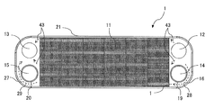
- FIG. 6A is a front view of the plate heat exchanger according to Embodiment 4 of the present invention in a state where the first heat transfer plate 1, the inner fin, and the second heat transfer plate 2 are stacked
- FIG. 6A is a sectional view taken along line AA in FIG. 6A
- FIG. 6C is a sectional view taken along line BB in FIG. 6A
- FIG. 6D is a sectional view taken along line CC in FIG.
- FIG. 6F is a cross-sectional view taken along the line EE in FIG. 6A
- FIG. 6G is a cross-sectional view taken along the line FF in FIG. 6A.
- the inner fin according to the fourth embodiment has the side fins 23, as shown in FIGS. 6A to 6G, the first passage hole 12 serving as the inner fin and the first fluid outlet and the second fluid inlet and the second fluid are provided. It is characterized in that the distance from the passage hole 13 is shorter than the distance from the first adjacent hole 14 and the second adjacent hole 15 serving as the second fluid outflow inlet.
- the first heat transfer plate 1 and the second heat transfer plate 2 have a heat transfer surface 11 a that is corrugated. Also good. In that case, the distance between the corrugated heat transfer surface 11a and the first passage hole 12 and the second passage hole 13 serving as the first fluid outflow inlet is the first adjacent position serving as the second fluid outflow inlet. It has a shape that is shorter than the distance between the hole 14 and the second adjacent hole 15.
- the side fins 23 having the shape of “L” in the vicinity of the first passage hole 12 and the second passage hole 13 which are the first fluid inflow / outflow ports, the first fluid inflow port and the outflow port are provided. It is possible to give resistance to the easy-to-flow passage. Therefore, compared with Embodiment 1, 2, since the expansion to the up-down direction in the bypass flow path 28 of a 1st fluid becomes large, the improvement of the in-plane distribution uniformization of a heat exchanger plate can further be aimed at.
- the inner fin has the side fins 23
- the effective heat transfer area of the header portion on the side of the heat transfer plate can be further increased.
- Embodiment 5 FIG.
- the same elements as those in the first to fourth embodiments are omitted, and the same or corresponding parts as those in the first to fourth embodiments are denoted by the same reference numerals.
- FIG. 7 is a front view showing a state in which the first heat transfer plate 1 and the inner fins of the plate heat exchanger according to Embodiment 5 of the present invention are stacked.
- FIG. 7 it is a figure which shows the state which laminated
- the inner fin is composed of the central fin 22 and the side fin 23, which are integrally formed.
- the central fin 22 is provided in the same shape as the inner fin 11 according to the first and second embodiments, and is disposed at the same position, and the side fin 23 is the left and right of the rectangular central fin 22. It is provided in a part on the outer side of both sides in the direction, and is disposed in the vicinity of the first passage hole 12 and the second passage hole 13 that are in the vicinity of the inflow outlet of the first heat transfer plate 1.
- the side fins 23 are characterized by having two or more “L” shapes arranged in accordance with the peripheral edge within half of the first passage hole 12 or the second passage hole 13.
- the side fins 23 having two or more “L” shapes in the vicinity of the first passage hole 12 and the second passage hole 13 which are the inlet and outlet of the first fluid, the flow of the first fluid
- the passage that is easy to flow from the inlet to the outlet can be more resistant than the third embodiment. Therefore, while maintaining the effect of the fourth embodiment, the in-plane distribution of the heat transfer plate can be further improved, and the effective heat transfer area of the header portion of the heat transfer plate can be increased.
- Embodiment 6 FIG.
- the same elements as those in the first to fifth embodiments are omitted, and the same reference numerals are given to the same or corresponding parts as those in the first to fifth embodiments.
- FIG. 8 is a front view showing a state in which the first heat transfer plate 1 and the inner fins of the plate heat exchanger according to Embodiment 6 of the present invention are stacked.
- FIG. 8 it is a figure which shows the state which laminated
- the inner fin is composed of the central fin 22 and the side fin 23, which are integrally formed.
- the central fin 22 is provided in the same shape as the inner fin 11 according to the first and second embodiments, and is disposed at the same position, and the side fin 23 is the left and right of the rectangular central fin 22. It is provided in a part on the outer side of both sides in the direction, and is disposed in the vicinity of the first passage hole 12 and the second passage hole 13 that are in the vicinity of the inflow outlet of the first heat transfer plate 1.
- the side fins 23 have a shape along the periphery of the first passage hole 12 or the second passage hole 13, and have a shape along the periphery of the first passage hole 12 or the second passage hole 13.
- the part which has is characterized by being arrange
- the side fins 23 having shapes along the periphery of the first passage hole 12 or the second passage hole 13 are respectively provided in the vicinity of the first passage hole 12 and the second passage hole 13 which are inflow / outflow ports of the first fluid.
- the in-plane distribution of the heat transfer plate can be further improved, and the effective heat transfer area of the header portion of the heat transfer plate can be increased.
- Embodiment 7 FIG.
- the same elements as those in the first to sixth embodiments are omitted, and the same or corresponding parts as those in the first to sixth embodiments are denoted by the same reference numerals.
- FIG. 9 is a front view showing a state in which the first heat transfer plate 1 and the inner fins of the plate heat exchanger according to Embodiment 7 of the present invention are stacked.
- FIG. 9 it is a figure which shows the state which laminated
- the inner fin is composed of the central fin 22 and the side fin 23, which are integrally formed.
- the central fin 22 is provided in the same shape as the inner fin 11 according to the first and second embodiments, and is disposed at the same position, and the side fin 23 is the left and right of the rectangular central fin 22. It is provided in a part on the outer side of both sides in the direction, and is disposed in the vicinity of the first passage hole 12 and the second passage hole 13 that are in the vicinity of the inflow outlet of the first heat transfer plate 1.
- the side fins 23 have a shape along the periphery of more than half of the first passage hole 12 or the second passage hole 13, and a shape along the periphery of the first passage hole 12 or the second passage hole 13.
- the portion having the is characterized by being arranged in accordance with the position of the peripheral edge of the first passage hole 12 or the second passage hole 13.
- an outlet 45 and a junction 46 are formed between the first passage hole 12 and the first adjacent hole 14 and between the second passage hole 13 and the second adjacent hole 15, respectively.
- a small flow path 44 is formed between the fins 23 and the outer wall 21.
- the side fins 23 having shapes along the periphery of the first passage hole 12 or the second passage hole 13 are respectively provided in the vicinity of the first passage hole 12 and the second passage hole 13 which are inflow / outflow ports of the first fluid.
- an outlet 45 and a junction 46 are formed between the first passage hole 12 and the first adjacent hole 14 and between the second passage hole 13 and the second adjacent hole 15, respectively.
- a small channel 44 is formed between the outer wall 23 and the outer wall 21.
- the strength of the heat exchanger can be improved by increasing the effective heat transfer area of the header portion of the heat transfer plate while maintaining the effect of the sixth embodiment.
- Embodiment 8 FIG. Hereinafter, the eighth embodiment will be described. However, the same elements as those in the first to seventh embodiments are omitted, and the same or corresponding parts as those in the first to seventh embodiments are denoted by the same reference numerals.
- FIG. 10 is a front view showing a state in which the first heat transfer plate 1 and the inner fins of the plate heat exchanger according to the eighth embodiment of the present invention are stacked.
- FIG. 10 it is a figure which shows the state which laminated
- the inner fin is composed of the central fin 22, the side fin 23, and the side fin 47, which are integrally formed.
- the central fin 22 is provided in the same shape as the inner fin 11 according to the first and second embodiments, and is disposed at the same position, and the side fin 23 is the left and right of the rectangular central fin 22. It is provided in a part on the outer side of both sides in the direction, and is disposed in the vicinity of the first passage hole 12 and the second passage hole 13 that are in the vicinity of the inflow outlet of the first heat transfer plate 1.
- the side fins 23 have a shape along the periphery of more than half of the first passage hole 12 or the second passage hole 13, and a shape along the periphery of the first passage hole 12 or the second passage hole 13.
- the portion having the is characterized by being arranged in accordance with the position of the peripheral edge of the first passage hole 12 or the second passage hole 13.
- an outlet 45 and a junction 46 are formed between the first passage hole 12 and the first adjacent hole 14 and between the second passage hole 13 and the second adjacent hole 15, respectively.
- a small flow path 44 is formed between the fins 23 and the outer wall 21.
- the side fins 47 are disposed at the outlet of the bypass channel 28 or the inlet of the combined channel 29, and between the peripheral wall 17 of the first adjacent hole 14 or the peripheral wall 18 of the second adjacent hole 15. A flow path is formed with a gap between them.
- the side fins 23 having shapes along the periphery of the first passage hole 12 or the second passage hole 13 are respectively provided in the vicinity of the first passage hole 12 and the second passage hole 13 which are inflow / outflow ports of the first fluid.
- an outlet 45 and a junction 46 are formed between the first passage hole 12 and the first adjacent hole 14 and between the second passage hole 13 and the second adjacent hole 15, respectively.
- a small channel 44 is formed between the outer wall 23 and the outer wall 21.
- side fins 47 are respectively provided at the outlet portion of the bypass flow path 28 or the inlet portion of the combined flow path 29 so as to flow between the peripheral wall 17 of the first adjacent hole 14 or the peripheral wall 18 of the second adjacent hole 15. Form a road. By doing so, it is possible to give resistance to the passage that is easy to flow from the inlet to the outlet of the first fluid as compared with the sixth embodiment. Therefore, the strength of the heat exchanger can be improved by increasing the effective heat transfer area of the header portion of the heat transfer plate while maintaining the effects of the seventh embodiment.
- Embodiment 9 FIG.
- the same elements as those in the first to eighth embodiments are omitted, and the same or corresponding parts as those in the first to eighth embodiments are denoted by the same reference numerals.
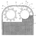
- FIG. 11A is an enlarged front view of the vicinity of the header portion of the heat transfer plate of the plate heat exchanger according to Embodiment 9 of the present invention
- FIG. 11B is an enlarged front view of the GG portion of FIG. 11A
- FIG. 11C is an enlarged front view of the HH portion of FIG. 11A.
- 11A shows an enlarged view of the periphery of the header portion of the first heat transfer plate 1, but the description of the illustration and illustration is omitted because the periphery of the header portion of the second heat transfer plate 2 has substantially the same configuration. To do.
- a protrusion 24 that protrudes from the rear surface side toward the front surface side is provided around the adjacent hole of the heat transfer plate.
- a plurality of convex portions 24 are provided along the circumferential direction outside the flanges 19 and 20 provided on the peripheral walls 17 and 18 of the first adjacent hole 14 and the second adjacent hole 15.
- the height of the convex portion 24 is set to be approximately the same as the thickness of the inner fin 11, when assembling the plate heat exchanger, it is brazed and joined to the rear surface of the adjacent heat transfer plate. . Therefore, compared with the first to eighth embodiments, the brazing area, that is, the junction area can be increased, so that the pressure strength can be further improved. Moreover, since the heat transfer area is increased by processing the convex portion 24, the heat transfer performance of the entire plate heat exchanger can be further improved.
- the shape of the convex portion 24 is not limited to the shape shown in FIG. 11B. As shown in FIGS. 11C (a) to 11 (f), the stagnation prevention in which the stagnation area is not formed in the circular shape and the wake portion as viewed from the front. A shape, an ellipse, a triangle, a quadrangle, an arc shape, or the like may be used, and a plurality of them may be provided in combination. Further, the size of the convex portion 24 is larger than four times the height between the heat transfer plates, and the interval between the adjacent convex portions 24 is larger than the size of the convex portion 24.
- the arrangement of the protrusions 24 provided around the adjacent holes of the heat transfer plate is not limited to the diameter, number, and pitch shown in FIG. 11A, and may be different.
- the arrangement of the convex portions 24 is adjusted within a half range of the header having the adjacent hole.
- the purpose of providing the convex portions 24 is to improve the strength of the header.
- the provision of the convex portions 24 has a bad influence on the in-plane fluid distribution, so the number of the convex portions 24 is small. Better. Therefore, the arrangement of the pitches and positions of the convex portions 24 and the number of the convex portions 24 are adjusted so that the in-plane distribution of the heat transfer plate is improved while maintaining the strength of the header.
- Embodiment 10 FIG.
- the same elements as those in the first to ninth embodiments are omitted, and the same or corresponding parts as those in the first to ninth embodiments are denoted by the same reference numerals.
- FIG. 12A is an enlarged front view of the vicinity of the header portion of the heat transfer plate of the plate heat exchanger according to Embodiment 10 of the present invention
- FIG. 12B is an enlarged front view of the II portion of FIG. 12A
- FIG. 12C is an enlarged front view of the KK portion of FIG. 12A.
- FIG. 12A shows an enlarged view of the vicinity of the header portion of the first heat transfer plate 1, but the description of the illustration and illustration is omitted because the vicinity of the header portion of the second heat transfer plate 2 has a substantially similar configuration. To do.
- a slit portion 25 for forming a slit around the passage hole of the first heat transfer plate 1 and on the front side is provided.
- the slit portion 25 protrudes from the peripheral edge 12a, 13a of the first passage hole 12 and the second passage hole 13 toward the front surface side, and from there, the first passage hole 12, It is provided toward the outside of the second passage hole 13.
- the first passage hole 12 and the second passage hole 13 are provided from the outer sides 12 a and 13 a toward the inner side, that is, toward the first passage hole 12 and the second passage hole 13. It has been.
- a slit 25 a is formed between the adjacent slit portions 25.
- the brazing area that is, the junction area can be increased, so that the pressure strength can be further improved.
- the heat transfer area is increased by processing the slit portion 25, the heat transfer performance of the entire plate heat exchanger can be further improved.
- the shape of the slit portion 25 is not limited to the shape shown in FIG. 12B. As shown in FIGS. 12C (a) to 12 (f), when viewed from the front, an arc shape, an ellipse, a triangle, a quadrangle, and a trapezoid. Etc., or a combination thereof may be provided. Further, the arrangement of the slit portions 25 provided around the passage holes of the heat transfer plate is not limited to the diameter, number, and pitch shown in FIG. 12A, that is, the width of the slit 25a, and may be different. It is not limited to uniform and may be non-uniform. The non-uniform slit 25a width distribution standard is to improve the in-plane distribution of the heat transfer plate while having strength.
- Embodiment 11 FIG.
- the same elements as those in the first to tenth embodiments are omitted, and the same or corresponding parts as those in the first to tenth embodiments are denoted by the same reference numerals.
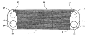
- FIG. 13A is an enlarged front view of the vicinity of the header portion of the heat transfer plate of the plate heat exchanger according to Embodiment 11 of the present invention
- FIG. 13B is an enlarged front view of the JJ portion of FIG. 13A. It is.
- FIG. 13A shows an enlarged view of the vicinity of the header portion of the first heat transfer plate 1, the description of the illustration and illustration is omitted because the periphery of the header portion of the second heat transfer plate 2 has substantially the same configuration. To do.
- a slit portion 25 is provided around the passage hole of the heat transfer plate and on the front side, and a convex portion 26 protruding from the rear side toward the front side is provided around the slit portion 25. It has been. Specifically, a plurality of slit portions 25 are provided along the circumferential direction outside the flanges 19 and 20 provided on the peripheral walls 17 and 18 of the first adjacent hole 14 and the second adjacent hole 15, and the slits are further provided. A plurality of convex portions 26 are provided outside the portion 25 along the circumferential direction.
- the brazing area that is, the junction area can be increased as compared with the first to tenth embodiments, so that the pressure strength can be further improved.
- the heat transfer area is increased by processing the convex portions 26, the heat transfer performance of the entire plate heat exchanger can be further improved.
- the shape of the convex portion 26 is not limited to the shape shown in FIG. 13A, and as shown in FIGS. 13B (a) to 13 (f), when viewed from the front, a circular shape, an anti-stagnation shape, an elliptical shape, a triangular shape, a quadrangular shape, An arc shape or the like may be used, and a plurality of them may be provided in combination. Further, the size of the convex portion 26 is larger than four times the height between the heat transfer plates, and the interval between the adjacent convex portions 26 is larger than the size of the convex portion 26.
- the arrangement of the protrusions 26 provided around the adjacent holes of the heat transfer plate is not limited to the diameter, number, and pitch shown in FIG. 13A, and may be different.
- the arrangement of the convex portions 26 is adjusted within a half range of the header having the adjacent hole. The standard of adjustment is to improve the in-plane distribution of the heat transfer plate while having strength.
- Embodiment 12 FIG. In the following, the same elements as those in the first to eleventh embodiments are omitted, and the same or corresponding parts as those in the first to eleventh embodiments are denoted by the same reference numerals.
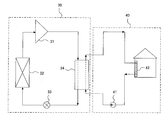
- FIG. 14 is a schematic diagram showing a configuration of a heat pump heating and hot water supply system according to Embodiment 12 of the present invention.
- the heat pump heating / hot water supply system includes a main refrigerant circuit 30 in which a compressor 31, a heat exchanger 32, an expansion valve 33, and a heat exchanger 34 are sequentially connected, a heat exchanger 34, a heating / hot water use device 42, and heating / hot water. And a water circuit 40 to which a pump 41 is sequentially connected.
- the heat exchanger 34 is the inner fin type plate heat exchanger described in the above embodiment. Moreover, the compressor 31, the heat exchanger 32, the expansion valve 33, the heat exchanger 34, and the main refrigerant circuit 30 which connects these sequentially are accommodated in a unit, and this is called a heat pump apparatus.
- the inner fin type plate heat exchanger has good heat exchange efficiency and high reliability. Therefore, when an inner fin type plate heat exchanger is mounted on the heat pump type heating and hot water supply system described in the twelfth embodiment, the heat pump type heating can efficiently reduce power consumption and reduce CO 2 emissions. A hot water supply system can be realized.
- the heat pump type heating and hot water supply system in which heat is exchanged between the refrigerant and water using the inner fin type plate heat exchanger described in the above embodiment has been described.
- the present invention is not limited to this, and the inner fin type plate heat exchanger described in the above embodiments can be used in many industrial and household equipment such as power generation and food heat sterilization treatment equipment such as chillers for cooling. It is.
- the present invention can be used in a heat pump apparatus that is easy to manufacture, improves heat exchange performance, and needs to improve energy saving performance.
Landscapes
- Engineering & Computer Science (AREA)
- Physics & Mathematics (AREA)
- Thermal Sciences (AREA)
- Mechanical Engineering (AREA)
- General Engineering & Computer Science (AREA)
- Heat-Exchange Devices With Radiators And Conduit Assemblies (AREA)
Abstract
Description
図1Aは、本発明の実施の形態1に係るプレート式熱交換器100の分解斜視図であり、図1Bは、本発明の実施の形態1に係るプレート式熱交換器100の第一伝熱プレート1とインナーフィン11とを積層した状態を示す正面図であり、図1Cは、本発明の実施の形態1に係るプレート式熱交換器100の第二伝熱プレート2とインナーフィン11とを積層した状態を示す正面図であり、図1Dは、本発明の実施の形態1に係るプレート式熱交換器100の第二伝熱プレート2の隣接孔を示す側面模式図であり、図1Eは、本発明の実施の形態1に係るプレート式熱交換器100の流体の流入通路を示す側面模式図であり、図1Fは、本発明の実施の形態1に係るプレート式熱交換器100の第一伝熱プレート1と第二伝熱プレート2とを積層した状態を示す側面模式図であり、図1Gは、本発明の実施の形態1に係るプレート式熱交換器100のインナーフィン11の型の例を示す模式図であり、図2は本発明の実施の形態1に係るプレート式熱交換器100の第二伝熱プレート2の第二隣接孔15の周壁18とインナーフィン11との間の隙間により面内速度分布および分配性能向上に影響検討図である。
なお、以下において、第一伝熱プレート1および第二伝熱プレート2の総称として伝熱プレートと称し、第一補強用サイドプレート3および第二補強用サイドプレート4の総称としてサイドプレートと称する。
なお、以下において、第一通路孔12および第二通路孔13の総称として通路孔と称し、第一隣接孔14および第二隣接孔15の総称として隣接孔と称し、第一ヘッダ部16および第二ヘッダ部27の総称としてヘッダ部と称する。
また、第一流体は、例えば水などであり、第二流体は、例えば冷媒のR410A、R32、R290、CO2などである。
また、第一マイクロチャンネル流路9は、本発明の「第一流路」に相当し、第二マイクロチャンネル流路10は、本発明の「第二流路」に相当する。
プレート式熱交換器100では、互いに隣接する第一伝熱プレート1と第二伝熱プレート2との間において、左右方向のインナーフィン11が配置されていない空間、つまり、第一伝熱プレート1の第一ヘッダ部16と第二伝熱プレート2の第一ヘッダ部16との間でインナーフィン11が配置されていない空間には、バイパス流路28が形成されており、第一伝熱プレート1の第二ヘッダ部27と第二伝熱プレート2の第二ヘッダ部27との間でインナーフィン11が配置されていない空間には、合流路29が形成されている。そして、バイパス流路28で上下方向へ広がりながら、左右方向へ流れ、マイクロチャンネル流路を流れることを特徴としている。また、本実施の形態1に係るバイパス流路28および合流路29は、伝熱プレートのインナーフィン11が配置されていない空間で、周壁17、18の内側を除いて、上下方向に流れる流体が隣接孔より遠い側を通過する全ての空間となるため、大きいことを特徴としている。
以下、本実施の形態2について説明するが、実施の形態1と重複するものについては省略し、実施の形態1と同じ部分または相当する部分には同じ符号を付す。
なお、図3では、第一伝熱プレート1の第二ヘッダ部27周辺を拡大した図を示しているが、第一伝熱プレート1の第一ヘッダ部16周辺、および、第二伝熱プレート2の第一ヘッダ16部周辺および第二ヘッダ27部周辺についてもほぼ同様の構成であるため、説明および図示を省略する。
以下、本実施の形態3について説明するが、実施の形態1および2と重複するものについては省略し、実施の形態1および2と同じ部分または相当する部分には同じ符号を付す。
以下、本実施の形態4について説明するが、実施の形態1~3と重複するものについては省略し、実施の形態1~3と同じ部分または相当する部分には同じ符号を付す。
なお、図5では、第一伝熱プレート1とインナーフィンとを積層した状態を示す図であり、それに基づいて説明するが、第二伝熱プレート2とインナーフィンとを積層した状態についてもほぼ同様の構成であるため、説明および図示を省略する。
以下、本実施の形態5について説明するが、実施の形態1~4と重複するものについては省略し、実施の形態1~4と同じ部分または相当する部分には同じ符号を付す。
なお、図7では、第一伝熱プレート1とインナーフィンとを積層した状態を示す図であり、それに基づいて説明するが、第二伝熱プレート2とインナーフィンとを積層した状態についてもほぼ同様の構成であるため、説明および図示を省略する。
以下、本実施の形態6について説明するが、実施の形態1~5と重複するものについては省略し、実施の形態1~5と同じ部分または相当する部分には同じ符号を付す。
なお、図8では、第一伝熱プレート1とインナーフィンとを積層した状態を示す図であり、それに基づいて説明するが、第二伝熱プレート2とインナーフィンとを積層した状態についてもほぼ同様の構成であるため、説明および図示を省略する。
以下、本実施の形態7について説明するが、実施の形態1~6と重複するものについては省略し、実施の形態1~6と同じ部分または相当する部分には同じ符号を付す。
なお、図9では、第一伝熱プレート1とインナーフィンとを積層した状態を示す図であり、それに基づいて説明するが、第二伝熱プレート2とインナーフィンとを積層した状態についてもほぼ同様の構成であるため、説明および図示を省略する。
以下、本実施の形態8について説明するが、実施の形態1~7と重複するものについては省略し、実施の形態1~7と同じ部分または相当する部分には同じ符号を付す。
なお、図10では、第一伝熱プレート1とインナーフィンとを積層した状態を示す図であり、それに基づいて説明するが、第二伝熱プレート2とインナーフィンとを積層した状態についてもほぼ同様の構成であるため、説明および図示を省略する。
以下、本実施の形態9について説明するが、実施の形態1~8と重複するものについては省略し、実施の形態1~8と同じ部分または相当する部分には同じ符号を付す。
なお、図11Aでは第一伝熱プレート1のヘッダ部周辺を拡大した図を示しているが、第二伝熱プレート2のヘッダ部周辺についてもほぼ同様の構成であるため、説明および図示を省略する。
以下、本実施の形態10について説明するが、実施の形態1~9と重複するものについては省略し、実施の形態1~9と同じ部分または相当する部分には同じ符号を付す。
なお、図12Aでは第一伝熱プレート1のヘッダ部周辺を拡大した図を示しているが、第二伝熱プレート2のヘッダ部周辺についてもほぼ同様の構成であるため、説明および図示を省略する。
また、伝熱プレートの通路孔の周囲に設けられるスリット部25の配置は、図12Aに示す径、数、ピッチつまりスリット25a幅に限定されず、異なるものであってもよく、スリット25a幅は均一に限らず不均一であってもよい。なお、不均一のスリット25a幅の分布標準は、強度を持ちながら伝熱プレートの面内分配性を向上することである。
以下、本実施の形態11について説明するが、実施の形態1~10と重複するものについては省略し、実施の形態1~10と同じ部分または相当する部分には同じ符号を付す。
なお、図13Aでは第一伝熱プレート1のヘッダ部周辺を拡大した図を示しているが、第二伝熱プレート2のヘッダ部周辺についてもほぼ同様の構成であるため、説明および図示を省略する。
以下、本実施の形態12について説明するが、実施の形態1~11と重複するものについては省略し、実施の形態1~11と同じ部分または相当する部分には同じ符号を付す。
図14は、本発明の実施の形態12に係るヒートポンプ式暖房給湯システムの構成を示す概略図である。
ヒートポンプ式暖房給湯システムは、圧縮機31、熱交換器32、膨張弁33、熱交換器34が順次接続された主冷媒回路30と、熱交換器34、暖房給湯用水利用装置42、暖房給湯用水ポンプ41が順次接続された水回路40と、を備える。
Claims (18)
- 矩形の板状を有し、正面視して左右方向の一方の側部に第一流体の流入口である通路孔が形成され、正面視して左右方向の他方の側部に第一流体の流出口である通路孔が形成され、一方または他方の前記側部に第二流体の流入口である隣接孔が形成され、第二流体の前記隣接孔が形成された前記側部と反対側の前記側部に第二流体の流出口である隣接孔が形成された第一伝熱プレートと、
矩形の板状を有し、正面視して左右方向の一方の側部に第一流体の流入口である隣接孔が形成され、正面視して左右方向の他方の側部に第一流体の流出口である隣接孔が形成され、一方または他方の前記側部に第二流体の流入口である通路孔が形成され、第二流体の前記通路孔が形成された前記側部と反対側の前記側部に第二流体の流出口である通路孔が形成された第二伝熱プレートと、を備え、
前記第一伝熱プレートおよび前記第二伝熱プレートが交互に複数積層され、第一流体の流入口から流出口に向かって第一流体が正面視して左右方向に流れる第一流路と、第二流体の流入口から流出口に向かって第二流体が正面視して左右方向に流れる第二流路とが、前記第一伝熱プレートと前記第二伝熱プレートとの間に積層方向に交互に形成され、前記第一流路を流れる第一流体と前記第二流路を流れる第二流体とで熱交換を行うプレート式熱交換器であって、
前記第一伝熱プレートと前記第二伝熱プレートとの間にインナーフィンを有し、または、前記第一伝熱プレートおよび前記第二伝熱プレートは波形加工された伝熱面を有し、
前記隣接孔の周縁には厚み方向に周壁が設けられており、該周壁の前面側にはフランジが設けられており、
前記第一伝熱プレートまたは前記第二伝熱プレートに設けられた前記フランジは、隣接する前記第一伝熱プレートまたは前記第二伝熱プレートの後面と接合されており、
隣接する前記第一伝熱プレートと前記第二伝熱プレートとの間の前記第一流路および前記第二流路の上流側には、第一流体の流入口から流入した第一流体、または、第二流体の流入口から流入した第二流体が、正面視して、上下方向へ広がりながら、前記隣接孔より遠い側を通過して、前記インナーフィンまたは波形加工された前記伝熱面に流入するバイパス流路と、前記バイパス流路を経ずに直接に前記インナーフィンまたは波形加工された前記伝熱面に向かって流れるメイン流路と、が形成されており、
前記隣接孔の全周に平坦な空間が形成されており、前記周壁と前記インナーフィンまたは波形加工された前記伝熱面との間の前記空間において前記メイン流路と前記バイパス流路とを流れた第一流体または第二流体が合流する
ことを特徴とするプレート式熱交換器。 - 前記隣接孔の前記周壁と前記インナーフィンまたは波形加工された前記伝熱面との間の隙間の長さは、前記周壁の高さに比べ3倍以上である
ことを特徴とする請求項1に記載のプレート式熱交換器。 - 前記インナーフィンまたは波形加工された前記伝熱面は、
前記隣接孔との距離よりも、前記通路孔との距離の方が短い
ことを特徴とする請求項1または2に記載のプレート式熱交換器。 - 前記フランジは、
前記周壁の外側に向かって設けられている
ことを特徴とする請求項1~3のいずれか一項に記載のプレート式熱交換器。 - 前記フランジは、
前記周壁の内側に向かって設けられている
ことを特徴とする請求項1~3のいずれか一項に記載のプレート式熱交換器。 - 前記第一伝熱プレートの後面と前記第二伝熱プレートの前記フランジ、および、前記第二伝熱プレートの後面と前記第一伝熱プレートの前記フランジは、それぞれ接合されている
ことを特徴とする請求項1~5のいずれか一項に記載のプレート式熱交換器。 - 隣接する前記第一伝熱プレートと前記第二伝熱プレートとの間の前記第一流路および前記第二流路の下流側には、前記第一流路を流れた第一流体を合流させる、または、前記第二流路を流れた第二流体を合流させる、合流路が形成されている
ことを特徴とする請求項1~6のいずれか一項に記載のプレート式熱交換器。 - 前記隣接孔の周囲に前記第一伝熱プレートまたは前記第二伝熱プレートの後面側から正面側に向かって突出した凸部が複数設けられている
ことを特徴とする請求項1~7のいずれか一項に記載のプレート式熱交換器。 - 前記通路孔の周囲に前記第一伝熱プレートまたは前記第二伝熱プレートの後面側から正面側に向かって突出した凸部が複数設けられている
ことを特徴とする請求項1~8のいずれか一項に記載のプレート式熱交換器。 - 複数の前記凸部は、
正面視して、円形、淀み防止形、楕円形、三角形、四角形、円弧状形のいずれか一つの形状で、または複数の形状を組み合わせて設けられている
ことを特徴とする請求項8または9に記載のプレート式熱交換器。 - 前記通路孔の周縁に複数のスリット部が設けられており、隣接するスリット部間にはスリットが形成されている
ことを特徴とする請求項1~10のいずれか一項に記載のプレート式熱交換器。 - 前記スリット部は、
前記通路孔の周縁から前面側に向かって突出し、そこから前記通路孔の外側に向かって設けられている
ことを特徴とする請求項11に記載のプレート式熱交換器。 - 前記スリット部は、
前記通路孔の周縁の外側から前記通路孔内に向かって設けられている
ことを特徴とする請求項11に記載のプレート式熱交換器。 - 複数の前記スリット部は、
正面視して、円弧状形、楕円形、三角形、四角形、台形のいずれか一つの形状で、または複数の形状を組み合わせて設けられている
ことを特徴とする請求項11~13のいずれか一項に記載のプレート式熱交換器。 - 前記インナーフィンは、
オフセット型、平板フィン型、波状フィン型、ルーバ型、コルゲートフィン型のいずれか一つ、または複数を組み合わせて設けられている
ことを特徴とする請求項1~14のいずれか一項に記載のプレート式熱交換器。 - 前記第一伝熱プレートおよび前記第二伝熱プレートは、
外周に厚み方向に突出した外壁が設けられており、
前記外壁は、厚み方向に対して外側に傾斜して設けられており、
前記第一伝熱プレートまたは前記第二伝熱プレートの前記外壁の内側と、他の隣接する前記第一伝熱プレートまたは前記第二伝熱プレートの前記外壁の外側との接触部分とは、接合されている
ことを特徴とする請求項1~15のいずれか一項に記載のプレート式熱交換器。 - 前記インナーフィンは、
前記通路孔の周縁に沿った形状を有しており、
前記通路孔の周縁に沿った形状を有する部分は前記通路孔の周縁の位置に合わせて配置されている
ことを特徴とする請求項1~16のいずれか一項に記載のプレート式熱交換器。 - 圧縮機、熱交換器、膨張弁、請求項1~17のいずれか一項に記載のプレート式熱交換器、が順次接続された主冷媒回路と、
前記プレート式熱交換器、暖房給湯用水利用装置、暖房給湯用水ポンプ、が順次接続された水回路と、を備えた
ことを特徴とするヒートポンプ式暖房給湯システム。
Priority Applications (4)
| Application Number | Priority Date | Filing Date | Title |
|---|---|---|---|
| JP2017566566A JP6567097B2 (ja) | 2016-02-12 | 2017-01-19 | プレート式熱交換器、およびそれを備えたヒートポンプ式暖房給湯システム |
| CN201780009715.5A CN108603732B (zh) | 2016-02-12 | 2017-01-19 | 板式热交换器及具备板式热交换器的热泵式制热供热水系统 |
| US16/066,744 US10907906B2 (en) | 2016-02-12 | 2017-01-19 | Plate heat exchanger and heat pump heating and hot water supply system including the plate heat exchanger |
| EP17750047.7A EP3415854B1 (en) | 2016-02-12 | 2017-01-19 | Plate-type heat exchanger and heat-pump-type heating and hot-water supply system equipped with same |
Applications Claiming Priority (2)
| Application Number | Priority Date | Filing Date | Title |
|---|---|---|---|
| JP2016-024704 | 2016-02-12 | ||
| JP2016024704 | 2016-02-12 |
Related Child Applications (1)
| Application Number | Title | Priority Date | Filing Date |
|---|---|---|---|
| US16/186,792 Continuation US20190076709A1 (en) | 2016-05-13 | 2018-11-12 | Tubular body designing method, golf club shaft designing method, and golf club shaft |
Publications (1)
| Publication Number | Publication Date |
|---|---|
| WO2017138322A1 true WO2017138322A1 (ja) | 2017-08-17 |
Family
ID=59563156
Family Applications (1)
| Application Number | Title | Priority Date | Filing Date |
|---|---|---|---|
| PCT/JP2017/001808 Ceased WO2017138322A1 (ja) | 2016-02-12 | 2017-01-19 | プレート式熱交換器、およびそれを備えたヒートポンプ式暖房給湯システム |
Country Status (5)
| Country | Link |
|---|---|
| US (1) | US10907906B2 (ja) |
| EP (1) | EP3415854B1 (ja) |
| JP (1) | JP6567097B2 (ja) |
| CN (1) | CN108603732B (ja) |
| WO (1) | WO2017138322A1 (ja) |
Cited By (5)
| Publication number | Priority date | Publication date | Assignee | Title |
|---|---|---|---|---|
| CN108413789A (zh) * | 2018-04-19 | 2018-08-17 | 天津三电汽车空调有限公司 | 一种新型钎焊式矩形通道板换热器 |
| WO2018216245A1 (ja) * | 2017-05-23 | 2018-11-29 | 三菱電機株式会社 | プレート式熱交換器及びヒートポンプ式給湯システム |
| WO2020001125A1 (zh) * | 2018-06-29 | 2020-01-02 | 浙江三花汽车零部件有限公司 | 一种换热器 |
| DE102019210238A1 (de) * | 2019-07-10 | 2021-01-14 | Mahle International Gmbh | Stapelscheibenwärmetauscher |
| WO2024014495A1 (ja) * | 2022-07-13 | 2024-01-18 | ダイキン工業株式会社 | 熱交換器、冷媒サイクル装置、給湯器 |
Families Citing this family (20)
| Publication number | Priority date | Publication date | Assignee | Title |
|---|---|---|---|---|
| GB2552801B (en) * | 2016-08-10 | 2021-04-07 | Hs Marston Aerospace Ltd | Heat exchanger device |
| JP1653096S (ja) * | 2018-11-26 | 2020-02-17 | ||
| JP1653095S (ja) * | 2018-11-26 | 2020-02-17 | ||
| JP1653094S (ja) * | 2018-11-26 | 2020-02-17 | ||
| WO2020161727A1 (en) * | 2019-02-05 | 2020-08-13 | Pranav Vikas India Pvt Limited | Universal heat exchanger |
| IT201900000665U1 (it) * | 2019-02-27 | 2020-08-27 | Onda S P A | Scambiatore di calore a piastre. |
| CN109855436A (zh) * | 2019-02-27 | 2019-06-07 | 西安交通大学 | 剑鱼梭型-倾斜沟槽仿生微细通道冷凝器 |
| JP7122469B2 (ja) * | 2019-06-05 | 2022-08-19 | 株式会社日阪製作所 | プレート式熱交換器、及びプレート式熱交換器用の分配器 |
| US11340027B2 (en) * | 2019-07-15 | 2022-05-24 | Modine Manufacturing Company | Tube for a heat exchanger, and method of making the same |
| JP7538991B2 (ja) * | 2020-06-02 | 2024-08-23 | パナソニックIpマネジメント株式会社 | 熱交換器 |
| CN112414185B (zh) * | 2020-09-17 | 2022-06-21 | 浙江三花智能控制股份有限公司 | 板式换热器 |
| US11633799B2 (en) * | 2020-10-01 | 2023-04-25 | Hamilton Sundstrand Corporation | Control assembly fabrication via brazing |
| IT202000026251A1 (it) * | 2020-11-04 | 2022-05-04 | Ibs Tech Spa | Scambiatore di calore |
| JP7707621B2 (ja) * | 2021-04-08 | 2025-07-15 | 株式会社デンソー | 熱交換器 |
| CN113365469B (zh) * | 2021-05-08 | 2022-07-29 | 北京无线电测量研究所 | 一种液冷板 |
| RS67070B1 (sr) | 2022-12-26 | 2025-08-29 | Euro Heat Doo | Izmenjivač toplote sa zavarenim unutrašnjim izmenjivačkim pločama |
| CN118293591A (zh) * | 2023-01-05 | 2024-07-05 | 法雷奥汽车空调湖北有限公司 | 中间热交换器及热交换组件 |
| SE2350827A1 (en) | 2023-07-03 | 2025-01-04 | Alfa Laval Corp Ab | Plate heat exchanger and heat pump circuit |
| WO2025065251A1 (zh) * | 2023-09-26 | 2025-04-03 | 罗伯特•博世有限公司 | 热交换器和控制器 |
| WO2026013587A1 (en) * | 2024-07-10 | 2026-01-15 | Ufi Innovation Center S.R.L. | Heat exchanger |
Citations (5)
| Publication number | Priority date | Publication date | Assignee | Title |
|---|---|---|---|---|
| JP2000310497A (ja) * | 1999-04-27 | 2000-11-07 | Toyo Radiator Co Ltd | 高温ガス用カッププレート型熱交換器およびその製造方法 |
| JP2007205634A (ja) * | 2006-02-01 | 2007-08-16 | Hisaka Works Ltd | プレート式熱交換器 |
| WO2008023732A1 (en) | 2006-08-23 | 2008-02-28 | Tokyo Braze Co., Ltd. | Highly pressure-resistant compact heat exchanger, container for occluding hydrogen, and method of producing them |
| JP2012002425A (ja) * | 2010-06-16 | 2012-01-05 | Mitsubishi Electric Corp | プレート式熱交換器及びヒートポンプ装置 |
| WO2012063355A1 (ja) * | 2010-11-12 | 2012-05-18 | 三菱電機株式会社 | プレート式熱交換器及びヒートポンプ装置 |
Family Cites Families (21)
| Publication number | Priority date | Publication date | Assignee | Title |
|---|---|---|---|---|
| US2777674A (en) * | 1953-05-29 | 1957-01-15 | Creamery Package Mfg Co | Plate type heat exchanger |
| US3460611A (en) * | 1967-10-06 | 1969-08-12 | Gen Motors Corp | Heat exchanger of plate fin modules |
| DE3622316C1 (de) | 1986-07-03 | 1988-01-28 | Schmidt W Gmbh Co Kg | Plattenwaermeaustauscher |
| JPH063352B2 (ja) * | 1987-07-27 | 1994-01-12 | 栄産業株式会社 | パネル型熱交換器 |
| US20010030043A1 (en) * | 1999-05-11 | 2001-10-18 | William T. Gleisle | Brazed plate heat exchanger utilizing metal gaskets and method for making same |
| JP2001099585A (ja) * | 1999-09-30 | 2001-04-13 | Denso Corp | アルミニウム製熱交換器 |
| JP2001280887A (ja) * | 2000-03-30 | 2001-10-10 | Hisaka Works Ltd | プレート式熱交換器 |
| DE10021481A1 (de) * | 2000-05-03 | 2001-11-08 | Modine Mfg Co | Plattenwärmetauscher |
| JP2002022374A (ja) | 2000-07-07 | 2002-01-23 | Hitachi Ltd | プレート式熱交換器および冷凍空調装置 |
| JP2002107074A (ja) * | 2000-09-29 | 2002-04-10 | Sanyo Electric Co Ltd | プレート型熱交換器及びそれを用いたヒートポンプ給湯機 |
| JP2002168591A (ja) | 2000-11-29 | 2002-06-14 | Denso Corp | アルミニウム製熱交換器 |
| CA2383649C (en) | 2002-04-24 | 2009-08-18 | Long Manufacturing Ltd. | Inverted lid sealing plate for heat exchanger |
| US20060237184A1 (en) * | 2005-04-20 | 2006-10-26 | Yuri Peric | Tubular flapper valves |
| ITPN20050090A1 (it) * | 2005-12-13 | 2007-06-14 | Domnick Hunter Hiross Spa | Essiccatore di gas compressi umidi |
| US8191615B2 (en) * | 2006-11-24 | 2012-06-05 | Dana Canada Corporation | Linked heat exchangers having three fluids |
| US7658082B2 (en) * | 2007-02-01 | 2010-02-09 | Cotherm Of America Corporation | Heat transfer system and associated methods |
| CN102027306B (zh) * | 2008-03-13 | 2013-01-16 | 丹佛斯公司 | 双板热交换器 |
| KR101225357B1 (ko) * | 2008-04-04 | 2013-01-22 | 알파 라발 코포레이트 에이비 | 플레이트형 열교환기 |
| SE532524C2 (sv) * | 2008-06-13 | 2010-02-16 | Alfa Laval Corp Ab | Värmeväxlarplatta samt värmeväxlarmontage innefattandes fyra plattor |
| CN202792543U (zh) | 2012-08-17 | 2013-03-13 | 上海日立电器有限公司 | 一种二氧化碳热泵热水器水侧回路结构 |
| EP2998676B1 (en) * | 2014-09-17 | 2022-09-07 | VALEO AUTOSYSTEMY Sp. z o.o. | Heat exchanger, in particular a condenser |
-
2017
- 2017-01-19 US US16/066,744 patent/US10907906B2/en active Active
- 2017-01-19 JP JP2017566566A patent/JP6567097B2/ja active Active
- 2017-01-19 WO PCT/JP2017/001808 patent/WO2017138322A1/ja not_active Ceased
- 2017-01-19 EP EP17750047.7A patent/EP3415854B1/en active Active
- 2017-01-19 CN CN201780009715.5A patent/CN108603732B/zh active Active
Patent Citations (5)
| Publication number | Priority date | Publication date | Assignee | Title |
|---|---|---|---|---|
| JP2000310497A (ja) * | 1999-04-27 | 2000-11-07 | Toyo Radiator Co Ltd | 高温ガス用カッププレート型熱交換器およびその製造方法 |
| JP2007205634A (ja) * | 2006-02-01 | 2007-08-16 | Hisaka Works Ltd | プレート式熱交換器 |
| WO2008023732A1 (en) | 2006-08-23 | 2008-02-28 | Tokyo Braze Co., Ltd. | Highly pressure-resistant compact heat exchanger, container for occluding hydrogen, and method of producing them |
| JP2012002425A (ja) * | 2010-06-16 | 2012-01-05 | Mitsubishi Electric Corp | プレート式熱交換器及びヒートポンプ装置 |
| WO2012063355A1 (ja) * | 2010-11-12 | 2012-05-18 | 三菱電機株式会社 | プレート式熱交換器及びヒートポンプ装置 |
Cited By (9)
| Publication number | Priority date | Publication date | Assignee | Title |
|---|---|---|---|---|
| WO2018216245A1 (ja) * | 2017-05-23 | 2018-11-29 | 三菱電機株式会社 | プレート式熱交換器及びヒートポンプ式給湯システム |
| CN108413789A (zh) * | 2018-04-19 | 2018-08-17 | 天津三电汽车空调有限公司 | 一种新型钎焊式矩形通道板换热器 |
| WO2020001125A1 (zh) * | 2018-06-29 | 2020-01-02 | 浙江三花汽车零部件有限公司 | 一种换热器 |
| US11971224B2 (en) | 2018-06-29 | 2024-04-30 | Zhejiang Sanhua Automotive Components Co., Ltd. | Plate-fin heat exchanger |
| DE102019210238A1 (de) * | 2019-07-10 | 2021-01-14 | Mahle International Gmbh | Stapelscheibenwärmetauscher |
| US11486658B2 (en) | 2019-07-10 | 2022-11-01 | Mahle International Gmbh | Stacked plate heat exchanger |
| WO2024014495A1 (ja) * | 2022-07-13 | 2024-01-18 | ダイキン工業株式会社 | 熱交換器、冷媒サイクル装置、給湯器 |
| JP2024012151A (ja) * | 2022-07-13 | 2024-01-25 | ダイキン工業株式会社 | 熱交換器、冷媒サイクル装置、給湯器 |
| JP7502700B2 (ja) | 2022-07-13 | 2024-06-19 | ダイキン工業株式会社 | 熱交換器、冷媒サイクル装置、給湯器 |
Also Published As
| Publication number | Publication date |
|---|---|
| CN108603732B (zh) | 2020-10-09 |
| EP3415854A1 (en) | 2018-12-19 |
| JP6567097B2 (ja) | 2019-08-28 |
| US20190017748A1 (en) | 2019-01-17 |
| EP3415854B1 (en) | 2021-04-21 |
| EP3415854A4 (en) | 2018-12-19 |
| JPWO2017138322A1 (ja) | 2018-06-21 |
| US10907906B2 (en) | 2021-02-02 |
| CN108603732A (zh) | 2018-09-28 |
Similar Documents
| Publication | Publication Date | Title |
|---|---|---|
| JP6567097B2 (ja) | プレート式熱交換器、およびそれを備えたヒートポンプ式暖房給湯システム | |
| JP5106453B2 (ja) | プレート式熱交換器及び冷凍空調装置 | |
| CN101802540B (zh) | 板层积式热交换器 | |
| US8656986B2 (en) | Fin, heat exchanger and heat exchanger assembly | |
| JP6529709B1 (ja) | プレート式熱交換器、ヒートポンプ装置およびヒートポンプ式冷暖房給湯システム | |
| US9766015B2 (en) | Heat exchanger | |
| JP6735918B2 (ja) | プレート式熱交換器及びヒートポンプ式給湯システム | |
| JP4827905B2 (ja) | プレート式熱交換器、及びこれを搭載した空気調和機 | |
| CN107078114A (zh) | 热交换器 | |
| CN105247312B (zh) | 换热器 | |
| US11060761B2 (en) | Plate heat exchanger and water heater including same | |
| KR20180060262A (ko) | 판형 열교환기 | |
| CN103502765A (zh) | 热交换器 | |
| CN112146484B (zh) | 板式换热器 | |
| JP2013122368A (ja) | 車両用熱交換器 | |
| WO2014034509A1 (ja) | 熱交換器 | |
| JP2010121925A (ja) | 熱交換器 | |
| WO2021115461A1 (zh) | 换热管和具有其的换热器 | |
| WO2020184315A1 (ja) | 熱交換器 | |
| JP7704858B2 (ja) | コイル型熱交換器及びその製造方法 | |
| JP6631664B2 (ja) | ヒートポンプ装置 | |
| JP2022147760A (ja) | プレート式熱交換器 | |
| WO2020203555A1 (ja) | 熱交換器 | |
| US20190162478A1 (en) | Plate heat exchanger with dual flow path | |
| JP5506844B2 (ja) | プレート式熱交換器 |
Legal Events
| Date | Code | Title | Description |
|---|---|---|---|
| 121 | Ep: the epo has been informed by wipo that ep was designated in this application |
Ref document number: 17750047 Country of ref document: EP Kind code of ref document: A1 |
|
| ENP | Entry into the national phase |
Ref document number: 2017566566 Country of ref document: JP Kind code of ref document: A |
|
| NENP | Non-entry into the national phase |
Ref country code: DE |
|
| WWE | Wipo information: entry into national phase |
Ref document number: 2017750047 Country of ref document: EP |
|
| ENP | Entry into the national phase |
Ref document number: 2017750047 Country of ref document: EP Effective date: 20180912 |