WO2017139953A1 - 一种 dc-dc 电源控制电路及电子设备 - Google Patents
一种 dc-dc 电源控制电路及电子设备 Download PDFInfo
- Publication number
- WO2017139953A1 WO2017139953A1 PCT/CN2016/074048 CN2016074048W WO2017139953A1 WO 2017139953 A1 WO2017139953 A1 WO 2017139953A1 CN 2016074048 W CN2016074048 W CN 2016074048W WO 2017139953 A1 WO2017139953 A1 WO 2017139953A1
- Authority
- WO
- WIPO (PCT)
- Prior art keywords
- resistor
- power supply
- control circuit
- transistor
- supply control
- Prior art date
- Legal status (The legal status is an assumption and is not a legal conclusion. Google has not performed a legal analysis and makes no representation as to the accuracy of the status listed.)
- Ceased
Links
Classifications
-
- H—ELECTRICITY
- H02—GENERATION; CONVERSION OR DISTRIBUTION OF ELECTRIC POWER
- H02M—APPARATUS FOR CONVERSION BETWEEN AC AND AC, BETWEEN AC AND DC, OR BETWEEN DC AND DC, AND FOR USE WITH MAINS OR SIMILAR POWER SUPPLY SYSTEMS; CONVERSION OF DC OR AC INPUT POWER INTO SURGE OUTPUT POWER; CONTROL OR REGULATION THEREOF
- H02M3/00—Conversion of DC power input into DC power output
-
- H—ELECTRICITY
- H02—GENERATION; CONVERSION OR DISTRIBUTION OF ELECTRIC POWER
- H02H—EMERGENCY PROTECTIVE CIRCUIT ARRANGEMENTS
- H02H7/00—Emergency protective circuit arrangements specially adapted for specific types of electric machines or apparatus or for sectionalised protection of cable or line systems, and effecting automatic switching in the event of an undesired change from normal working conditions
- H02H7/10—Emergency protective circuit arrangements specially adapted for specific types of electric machines or apparatus or for sectionalised protection of cable or line systems, and effecting automatic switching in the event of an undesired change from normal working conditions for converters; for rectifiers
- H02H7/12—Emergency protective circuit arrangements specially adapted for specific types of electric machines or apparatus or for sectionalised protection of cable or line systems, and effecting automatic switching in the event of an undesired change from normal working conditions for converters; for rectifiers for static converters or rectifiers
- H02H7/1213—Emergency protective circuit arrangements specially adapted for specific types of electric machines or apparatus or for sectionalised protection of cable or line systems, and effecting automatic switching in the event of an undesired change from normal working conditions for converters; for rectifiers for static converters or rectifiers for DC-DC converters
-
- H—ELECTRICITY
- H02—GENERATION; CONVERSION OR DISTRIBUTION OF ELECTRIC POWER
- H02M—APPARATUS FOR CONVERSION BETWEEN AC AND AC, BETWEEN AC AND DC, OR BETWEEN DC AND DC, AND FOR USE WITH MAINS OR SIMILAR POWER SUPPLY SYSTEMS; CONVERSION OF DC OR AC INPUT POWER INTO SURGE OUTPUT POWER; CONTROL OR REGULATION THEREOF
- H02M1/00—Details of apparatus for conversion
- H02M1/14—Arrangements for reducing ripples from DC input or output
-
- H—ELECTRICITY
- H02—GENERATION; CONVERSION OR DISTRIBUTION OF ELECTRIC POWER
- H02M—APPARATUS FOR CONVERSION BETWEEN AC AND AC, BETWEEN AC AND DC, OR BETWEEN DC AND DC, AND FOR USE WITH MAINS OR SIMILAR POWER SUPPLY SYSTEMS; CONVERSION OF DC OR AC INPUT POWER INTO SURGE OUTPUT POWER; CONTROL OR REGULATION THEREOF
- H02M1/00—Details of apparatus for conversion
- H02M1/32—Means for protecting converters other than automatic disconnection
-
- H—ELECTRICITY
- H02—GENERATION; CONVERSION OR DISTRIBUTION OF ELECTRIC POWER
- H02M—APPARATUS FOR CONVERSION BETWEEN AC AND AC, BETWEEN AC AND DC, OR BETWEEN DC AND DC, AND FOR USE WITH MAINS OR SIMILAR POWER SUPPLY SYSTEMS; CONVERSION OF DC OR AC INPUT POWER INTO SURGE OUTPUT POWER; CONTROL OR REGULATION THEREOF
- H02M1/00—Details of apparatus for conversion
- H02M1/36—Means for starting or stopping converters
-
- H—ELECTRICITY
- H02—GENERATION; CONVERSION OR DISTRIBUTION OF ELECTRIC POWER
- H02M—APPARATUS FOR CONVERSION BETWEEN AC AND AC, BETWEEN AC AND DC, OR BETWEEN DC AND DC, AND FOR USE WITH MAINS OR SIMILAR POWER SUPPLY SYSTEMS; CONVERSION OF DC OR AC INPUT POWER INTO SURGE OUTPUT POWER; CONTROL OR REGULATION THEREOF
- H02M3/00—Conversion of DC power input into DC power output
- H02M3/02—Conversion of DC power input into DC power output without intermediate conversion into AC
- H02M3/04—Conversion of DC power input into DC power output without intermediate conversion into AC by static converters
- H02M3/10—Conversion of DC power input into DC power output without intermediate conversion into AC by static converters using discharge tubes with control electrode or semiconductor devices with control electrode
- H02M3/145—Conversion of DC power input into DC power output without intermediate conversion into AC by static converters using discharge tubes with control electrode or semiconductor devices with control electrode using devices of a triode or transistor type requiring continuous application of a control signal
- H02M3/155—Conversion of DC power input into DC power output without intermediate conversion into AC by static converters using discharge tubes with control electrode or semiconductor devices with control electrode using devices of a triode or transistor type requiring continuous application of a control signal using semiconductor devices only
- H02M3/156—Conversion of DC power input into DC power output without intermediate conversion into AC by static converters using discharge tubes with control electrode or semiconductor devices with control electrode using devices of a triode or transistor type requiring continuous application of a control signal using semiconductor devices only with automatic control of output voltage or current, e.g. switching regulators
-
- H—ELECTRICITY
- H02—GENERATION; CONVERSION OR DISTRIBUTION OF ELECTRIC POWER
- H02M—APPARATUS FOR CONVERSION BETWEEN AC AND AC, BETWEEN AC AND DC, OR BETWEEN DC AND DC, AND FOR USE WITH MAINS OR SIMILAR POWER SUPPLY SYSTEMS; CONVERSION OF DC OR AC INPUT POWER INTO SURGE OUTPUT POWER; CONTROL OR REGULATION THEREOF
- H02M1/00—Details of apparatus for conversion
- H02M1/0003—Details of control, feedback or regulation circuits
- H02M1/0016—Control circuits providing compensation of output voltage deviations using feedforward of disturbance parameters
- H02M1/0022—Control circuits providing compensation of output voltage deviations using feedforward of disturbance parameters the disturbance parameters being input voltage fluctuations
Definitions
- the present invention relates to the field of electronic device technologies, and in particular, to a DC-DC power supply control circuit and an electronic device.
- DC-DC power supply (“DC" or DC, English full name Direct Current) to supply power. If the output voltage of the DC-DC power supply is dithered, the load will be applied. The circuit works abnormally and even damages the load circuit. For example, in many in-vehicle electronic devices, due to the presence of a super capacitor at the input of the DC-DC power supply, the following conditions may occur during the power-down of the DC-DC power supply: The voltage of the super capacitor of the DC-DC power supply is reduced.
- the voltage of the super capacitor is less than the lower limit operating voltage of the DC-DC power supply, the DC-DC power supply is turned off, and the voltage of the super capacitor is rebounded after the DC-DC power supply is turned off, when the voltage of the super capacitor rebounds
- the DC-DC power supply is restarted, and the load of the super-capacitor is lowered due to the load increase after the DC-DC power supply is turned on, so that it is lower than the DC-DC power supply.
- Lower operating voltage which causes the DC-DC power supply to be turned off again. After the shutdown, the voltage of the super capacitor rebounds again.
- the present invention provides a DC-DC power supply control circuit and an electronic device for implementing low voltage self-shutdown protection of a DC-DC power supply.
- a first aspect of the present invention provides a DC-DC power supply control circuit, including: [0007] a Zener diode, a first resistor, a second resistor, a third resistor, a first transistor, and a second transistor; [0008] wherein one end of the first resistor and an input of a DC-DC power supply An end connection, and the other end of the first resistor is connected to an enable end of the DC-DC power supply;
- one end of the second resistor is connected to an enable end of the DC-DC power supply, and the other end of the second resistor is connected to a collector of the second triode;
- a base of the second triode is connected to a collector of the first triode, and an emitter of the second triode is grounded;
- the negative terminal of the Zener diode is connected to the output end of the DC-DC power supply, and the positive terminal of the Zener diode is connected to the base of the first transistor;
- one end of the third resistor is connected to the base of the first transistor, and the other end of the third resistor is grounded;
- the emitter of the first triode is grounded
- V inmin represents the lower limit operating voltage defined by the DC-DC power supply, V innOTmal
- V ⁇ indicating the turn-on voltage of the enable terminal of the DC-DC power supply
- R 2 indicating the resistance of the second resistor value
- the first resistor and the second resistor are specifically a sliding varistor.
- the first resistor and the second resistor are specifically resistors of a fixed resistance.
- the model of the DC-DC power supply is specifically MP2315
- a second aspect of the present invention provides a DC-DC power supply control circuit, including:
- one end of the first resistor is connected to an input end of the DC-DC power source, and the other end of the first resistor is connected to an enable end of the DC-DC power source;
- one end of the second resistor is connected to an enable end of the DC-DC power supply, and the other end of the second resistor is connected to a drain of the second field effect transistor;
- a gate of the second field effect transistor is connected to a drain of the first field effect transistor, and a source of the second field effect transistor is grounded;
- the negative terminal of the Zener diode is connected to the output end of the DC-DC power supply, and the positive terminal of the Zener diode is connected to the gate of the first FET;
- one end of the third resistor is connected to the gate of the first field effect transistor, and the other end of the third resistor is grounded;
- the resistance values of the first resistor and the second resistor satisfy the following conditions:
- V inmin represents the lower limit operating voltage defined by the DC-DC power supply, V innOTmal
- the first resistor and the second resistor are specifically a sliding varistor.
- the first resistor and the second resistor are specifically resistors of a fixed resistance.
- the model of the DC-DC power supply is specifically MP2315.
- a third aspect of the present invention provides an electronic device, including: a DC-DC power supply control circuit;
- the above DC-DC power supply control circuit is any one of the DC-DC power supply control circuits mentioned in the first aspect of the present invention; or the DC-DC power supply control circuit is as described in any of the DCs of the second aspect of the present invention. DC power control circuit.
- the present invention constructs a DC-DC power supply control circuit by using a Zener diode, a resistor, and a triode (or a field effect transistor), and changes the DC-DC power supply by turning on and off the triode (or FET).
- the input voltage of the enable terminal is used to realize the low-voltage self-shutdown protection of the DC-DC power supply, thereby solving the DC-induced fluctuation of the input voltage of the D C-DC power supply near the lower limit operating voltage of the DC-DC power supply.
- the D C power supply is repeatedly turned on and off.
- FIG. 1 is a schematic structural diagram of an embodiment of a DC-DC power supply control circuit according to an embodiment of the present invention
- FIG. 2 is a schematic structural diagram of another embodiment of a DC-DC power supply control circuit according to an embodiment of the present invention.
- a DC-DC power supply control circuit according to an embodiment of the present invention, as shown in FIG. 1, the DC-DC power supply control circuit in the embodiment of the present invention includes:
- a Zener diode 1 a first resistor 2, a second resistor 3, a third resistor 4, a first transistor 5 and a second transistor 6;
- one end of the first resistor 2 is connected to the input end 7 of the DC-DC power supply, and the other end of the first resistor 2 is connected to the enable end 8 of the DC - DC power supply;
- one end of the second resistor 3 is connected to the enable terminal 8 of the DC-DC power supply, and the other end of the second resistor 3 is connected to the collector of the second transistor 6;
- a base of the second transistor 6 is connected to a collector of the first transistor 5, and the second transistor
- the emitter of 6 is grounded
- the negative terminal of the Zener diode 1 is connected to the output terminal 9 of the DC-DC power supply, and the positive terminal of the Zener diode 1 is connected to the base of the first transistor 5;
- One end of the third resistor 4 is connected to the base of the first transistor 5, and the other end of the third resistor 4 is grounded;
- the emitter of the first transistor 5 is grounded
- the resistance values of the first resistor 2 and the second resistor 3 satisfy the following conditions:
- V inmin represents a lower limit operating voltage defined by the DC-DC power source, V innOTmal
- V ⁇ indicating the turn-on voltage of the enable terminal 8 of the DC-DC power supply
- R 2 indicating the second The resistance of the resistor 3.
- a power supply is connected to an input terminal 7 of a DC-DC power supply, an input voltage is supplied to the DC-DC power supply, and a load is connected to an output terminal 9 of the DC-DC power supply to pass the DC-DC power supply. Power the load.
- the first resistor 2 and the second resistor 3 are specifically sliding varistor.
- the first resistor 2 and the second resistor 3 may also satisfy the first formula and the second formula.
- a fixed resistance resistor is not limited here.
- the resistance of the third resistor is in the range of 10 ohms to 10,000 ohms.
- the resistance of the third resistor may be set according to actual conditions, which is not limited herein.
- the model of the DC-DC power supply in the embodiment of the present invention is specifically MP2315.
- the DC-DC power supply control circuit in the embodiment of the present invention can also be applied to other DC-DC power supplies with an enabled end.
- Medium here is not limited.
- the first transistor 5 is turned off, and the second transistor 6 is turned on.
- the voltage of the enable terminal 8 of the DC-DC power source is the voltage division of the first resistor 2 and the second resistor 3, enabling The turn-on voltage of the terminal 8 is increased. Since the resistance values of the first resistor 2 and the second resistor 3 satisfy the first formula, the voltage of the enable terminal 8 of the ⁇ DC-DC power supply is less than the turn-on voltage of the enable terminal 8.
- DC-DC power supply Shut down. Only when the voltage at the input terminal 7 of the DC-DC power supply rises significantly to the normal operating voltage defined by the DC-DC power supply, the voltage of the enable terminal 8 is greater than the voltage of the enable terminal 8, so that the voltage can be turned on again.
- the D C-DC power supply prevents the DC-DC power supply from being frequently turned on and off.
- the present invention constructs a DC-DC power supply control circuit by using a Zener diode, a resistor and a triode, and changes the input voltage of the DC-DC power supply enable terminal by turning on and off the triode, thereby realizing DC-DC.
- the low-voltage self-shutdown protection of the power supply further solves the problem that the DC-DC power supply is repeatedly turned on and off due to fluctuations in the input voltage of the DC-DC power supply near the lower limit operating voltage of the DC-DC power supply.
- a DC-DC power supply control circuit according to an embodiment of the present invention, as shown in FIG. 2, the DC-DC power supply control circuit in the embodiment of the present invention includes:
- one end of the first resistor 2 is connected to the input end 7 of the DC-DC power supply, and the other end of the first resistor 2 is connected to the enable end 8 of the DC - DC power supply;
- One end of the second resistor 3 is connected to the enable terminal 8 of the DC-DC power supply, and the other end of the second resistor 3 is connected to the drain of the second field effect transistor 11;
- a gate of the second field effect transistor 11 is connected to a drain of the first field effect transistor 10, and a source of the second field effect transistor 11 is grounded;
- the negative terminal of the Zener diode 1 is connected to the output terminal 9 of the DC-DC power supply, and the positive terminal of the Zener diode 1 is connected to the gate of the first FET 10;
- one end of the third resistor 4 is connected to the gate of the first field effect transistor 10, and the other end of the third resistor 4 is grounded;
- the resistance values of the first resistor 2 and the second resistor 3 satisfy the following conditions:
- V inmin represents the lower limit operating voltage defined by the DC-DC power supply, V innOTmal
- V ⁇ indicating the turn-on voltage of the enable terminal 8 of the DC-DC power supply
- R 2 indicating the second The resistance of the resistor 3.
- the power supply is connected to the input terminal 7 of the DC-DC power supply, and the input voltage is supplied to the DC-DC power supply, and the load is connected to the output terminal 9 of the DC-DC power supply to pass the DC-DC power supply. Power the load.
- the first resistor 2 and the second resistor 3 are specifically sliding varistor.
- the first resistor 2 and the second resistor 3 may also satisfy the first formula and the second formula.
- a fixed resistance resistor is not limited here.
- the resistance of the third resistor is in the range of 10 ohms to 10,000 ohms.
- the resistance of the third resistor may be set according to an actual situation, which is not limited herein.
- the model of the DC-DC power supply in the embodiment of the present invention is specifically MP2315.
- the DC-DC power supply control circuit in the embodiment of the present invention can also be applied to other DC-DC power supplies with an enabled end.
- Medium here is not limited.
- the voltage at the input terminal 7 of the DC-DC power supply drops to the lower limit operating voltage V inmin ⁇ defined by the DC-DC power supply
- the voltage at the output terminal 9 of the DC-DC power supply also drops, and the Zener diode 1 turns off. Breaking, the first FET 10 is turned off, and the second FET 11 is turned on.
- the voltage of the enable terminal 8 of the DC-DC power supply is the partial pressure of the first resistor 2 and the second resistor 3, enabling The turn-on voltage of the terminal 8 is increased. Since the resistance values of the first resistor 2 and the second resistor 3 satisfy the first formula, the voltage of the enable terminal 8 of the ⁇ DC-DC power supply is less than the turn-on voltage of the enable terminal 8.
- the DC-DC power supply is turned off.
- the voltage of the enable terminal 8 is greater than the voltage of the enable terminal 8, so that the voltage can be turned on again.
- the DC-DC power supply prevents the DC-DC power supply from being frequently turned on and off.
- the present invention constructs a DC-DC power supply control circuit by using a Zener diode, a resistor and a field effect transistor, and changes the input voltage of the DC-DC power supply enable end by turning on and off the FET. Realizing the low-voltage self-shutdown protection of the DC-D C power supply, thereby solving the repeated turn-on and turn-off of the DC-DC power supply caused by the fluctuation of the input voltage of the DC-DC power supply near the lower limit operating voltage of the DC-DC power supply The problem.
- An embodiment of the present invention provides an electronic device including a DC-DC power supply control circuit as described in Embodiment 1 or Embodiment 2.
- the electronic device in the embodiment of the present invention may be a mobile phone, a tablet computer, a palmtop computer, or other electronic device powered by a DC-DC power supply, which is not limited herein.
Landscapes
- Engineering & Computer Science (AREA)
- Power Engineering (AREA)
- Direct Current Feeding And Distribution (AREA)
Abstract
一种DC-DC电源控制电路及电子设备,其中,该DC-DC电源控制电路包括:稳压二极管(1)、第一电阻(2)、第二电阻(3)、第三电阻(4)、第一三极管(5)和第二三极管(6);第一电阻(2)的两端分别与DC-DC电源的输入端(7)和DC-DC电源的使能端(8)连接;第二电阻(3)的两端分别与DC-DC电源的使能端(8)和第二三极管(6)的集电极连接;第二三极管(6)的基极和发射极分别为与第一三极管(5)的集电极和地连接;稳压二极管(1)的负极端和正极端分别与DC-DC电源的输出端(9)和第一三极管(5)的基极连接;第三电阻(4)的两端分别与第一三极管(5)的基极和地连接;第一三极管(5)的发射极接地,从而实现了DC-DC电源的低压自我关断保护。
Description
一种 DC-DC电源控制电路及电子设备 技术领域
[0001] 本发明涉及电子设备技术领域, 具体涉及一种 DC-DC电源控制电路及电子设备 背景技术
[0002] 随着科技的发展, 电子设备的种类越来越多, 且功能也越来越强大。
[0003] 目前, 市面上采用直流供电的电子设备基本上都采用 DC-DC电源 ("DC"也即 直流, 英文全称为 Direct Current) 供电, DC-DC电源输出电压若产生抖动将会使 负载电路工作异常甚至损坏负载电路。 例如, 在很多车载电子设备中, 由于 DC- DC电源输入端超级电容的存在, 在该 DC-DC电源掉电的过程中将存在如下情况 : DC-DC电源的超级电容的电压减小, 当该超级电容的电压小于该 DC-DC电源 的下限工作电压吋, 该 DC-DC电源关断, 该 DC-DC电源关断后该超级电容的电 压会回弹, 当该超级电容的电压回弹到该 DC-DC电源的下限工作电压吋, 该 DC- DC电源重新幵启, 由于该 DC-DC电源幵启后负载加重使得该超级电容电压下降 , 使其又低于该 DC-DC电源的下限工作电压, 从而导致该 DC-DC电源又再次关 断, 关断后该超级电容的电压再次回弹, 当该超级电容的电压回弹到该 DC-DC 电源的下限工作电压吋, 该 DC-DC电源重新幵启, 如此反复多次。 在上述过程 中由于 DC-DC电源反复幵启和关断, 输出电压将产生波动, 对负载影响极大。
[0004] 目前并没有相关技术方案能够有效解决由于 DC-DC电源的输入电压在该 DC-DC 电源的下限工作电压附近波动而导致的该 DC-DC电源反复幵启和关断的问题。 技术问题
[0005] 本发明提供一种 DC-DC电源控制电路及电子设备, 用于实现 DC-DC电源的低压 自我关断保护。
问题的解决方案
技术解决方案
[0006] 本发明第一方面提供一种 DC-DC电源控制电路, 包括:
[0007] 稳压二极管、 第一电阻、 第二电阻、 第三电阻、 第一三极管和第二三极管; [0008] 其中, 所述第一电阻的一端与 DC-DC电源的输入端连接, 且所述第一电阻的另 一端与所述 DC-DC电源的使能端连接;
[0009] 所述第二电阻的一端与所述 DC-DC电源的使能端连接, 且所述第二电阻的另一 端与所述第二三极管的集电极连接;
[0010] 所述第二三极管的基极与所述第一三极管的集电极连接, 且所述第二三极管的 发射极接地;
[0011] 所述稳压二极管的负极端与所述 DC-DC电源的输出端连接, 且所述稳压二极管 的正极端与所述第一三极管的基极连接;
[0012] 所述第三电阻的一端与所述第一三极管的基极连接, 且所述第三电阻的另一端 接地;
[0013] 所述第一三极管的发射极接地;
[0014] 所述第一电阻和所述第二电阻的阻值满足如下条件:


[0017] 其中, V inmin表示所述 DC-DC电源限定的下限工作电压, V innOTmal
表示所述 DC-DC电源限定的正常工作电压, V∞表示所述 DC-DC电源的使能端 的幵启电压, 表示所述第一电阻的阻值, R 2表示所述第二电阻的阻值。
[0018] 基于本发明第一方面, 在第一种可能的实现方式中, 所述第一电阻和所述第二 电阻具体为滑动变阻器。
[0019] 基于本发明第一方面, 在第二种可能的实现方式中, 所述第一电阻和所述第二 电阻具体为固定阻值的电阻。
[0020] 基于本发明第一方面, 或者本发明第一方面的第一种可能的实现方式, 或者本 发明第一方面的第二种可能的实现方式, 在第三种可能的实现方式中, 所述 DC- DC电源的型号具体为 MP2315
[0021] 本发明第二方面提供一种 DC-DC电源控制电路, 包括:
[0022] 稳压二极管、 第一电阻、 第二电阻、 第三电阻、 第一场效应管和第二场效应管
[0023] 其中, 所述第一电阻的一端与 DC-DC电源的输入端连接, 且所述第一电阻的另 一端与所述 DC-DC电源的使能端连接;
[0024] 所述第二电阻的一端与所述 DC-DC电源的使能端连接, 且所述第二电阻的另一 端与所述第二场效应管的漏极连接;
[0025] 所述第二场效应管的栅极与所述第一场效应管的漏极连接, 且所述第二场效应 管的源极接地;
[0026] 所述稳压二极管的负极端与所述 DC-DC电源的输出端连接, 且所述稳压二极管 的正极端与所述第一场效应管的栅极连接;
[0027] 所述第三电阻的一端与所述第一场效应管的栅极连接, 且所述第三电阻的另一 端接地;
[0028] 所述第一场效应管的源极接地;
[0029] 其中, 所述第一电阻和所述第二电阻的阻值满足如下条件:
[0030]
V. - v :

[0031]
F: , » ( 2 ) > V :
ζ + ϋ
[0032] 其中, V inmin表示所述 DC-DC电源限定的下限工作电压, V innOTmal
表示所述 DC-DC电源限定的正常工作电压, V∞表示所述 DC-DC电源的使能端
的幵启电压, 表示所述第一电阻的阻值, R 2表示所述第二电阻的阻值。
[0033] 基于本发明第二方面, 在第一种可能的实现方式中, 所述第一电阻和所述第二 电阻具体为滑动变阻器。
[0034] 基于本发明第二方面, 在第二种可能的实现方式中, 所述第一电阻和所述第二 电阻具体为固定阻值的电阻。
[0035] 基于本发明第二方面, 或者本发明第一方面的第一种可能的实现方式, 或者本 发明第一方面的第二种可能的实现方式, 在第三种可能的实现方式中, 所述 DC- DC电源的型号具体为 MP2315。
发明的有益效果
有益效果
[0036] 本发明第三方面提供一种电子设备, 包括: DC-DC电源控制电路;
[0037] 上述 DC-DC电源控制电路如本发明第一方面提及的任一 DC-DC电源控制电路; 或者, 上述 DC-DC电源控制电路如本发明第二方面提及的任一 DC-DC电源控制 电路。
[0038] 由上可见, 本发明利用稳压二极管、 电阻和三极管 (或者场效应管) 构建 DC- DC电源控制电路, 用三极管 (或者场效应管) 的导通和关断改变 DC-DC电源使 能端的输入电压, 以此实现 DC-DC电源的低压自我关断保护, 进而解决了由于 D C-DC电源的输入电压在该 DC-DC电源的下限工作电压附近波动而导致的该 DC-D C电源反复幵启和关断的问题。
对附图的简要说明
附图说明
[0039] 为了更清楚地说明本发明实施例或现有技术中的技术方案, 下面将对实施例或 现有技术描述中所需要使用的附图作简单地介绍, 显而易见地, 下面描述中的 附图仅仅是本发明的一些实施例, 对于本领域普通技术人员来讲, 在不付出创 造性劳动性的前提下, 还可以根据这些附图获得其他的附图。
[0040] 图 1为本发明实施例提供的 DC-DC电源控制电路一个实施例结构示意图;
[0041] 图 2为本发明实施例提供的 DC-DC电源控制电路另一个实施例结构示意图。
本发明的实施方式
[0042] 为使得本发明的发明目的、 特征、 优点能够更加的明显和易懂, 下面将结合本 发明实施例ί中 . 的附图, 对本发明实施例中的技术方案进行清楚、 完整地描述, 显然, 所描述的实施例仅仅是本发明一部分实施例, 而非全部实施例。 基于本 发明中的实施例, 本领域普通技术人员在没有做出创造性劳动前提下所获得的 所有其他实施例, 都属于本 <i发明保护的范围。
[0043] 实施例一
[0044] 本发明实施例提供的一种 DC-DC电源控制电路, 请参阅图 1, 本发明实施例中 的 DC-DC电源控制电路包括:
[0045] 稳压二极管 1、 第一电阻 2、 第二电阻 3、 第三电阻 4、 第一三极管 5和第二三极 管 6;
[0046] 其中, 所述第一电阻 2的一端与 DC-DC电源的输入端 7连接, 且所述第一电阻 2 的另一端与所述 DC-DC电源的使能端 8连接;
[0047] 所述第二电阻 3的一端与所述 DC-DC电源的使能端 8连接, 且所述第二电阻 3的 另一端与所述第二三极管 6的集电极连接;
[0048] 所述第二三极管 6的基极与所述第一三极管 5的集电极连接, 且所述第二三极管
6的发射极接地;
[0049] 所述稳压二极管 1的负极端与所述 DC-DC电源的输出端 9连接, 且所述稳压二极 管 1的正极端与所述第一三极管 5的基极连接;
[0050] 所述第三电阻 4的一端与所述第一三极管 5的基极连接, 且所述第三电阻 4的另 一端接地;
[0051] 所述第一三极管 5的发射极接地;
[0052] 所述第一电阻 2和所述第二电阻 3的阻值满足如下条件:
[0053] . *
(为便于描述, 后续将其描述为第一公式) ;
[0054]
V -·

(为便于描述, 后续将其描述为第二公式) ;
[0055] 其中, V inmin表示所述 DC-DC电源限定的下限工作电压, V innOTmal
表示所述 DC-DC电源限定的正常工作电压, V∞表示所述 DC-DC电源的使能端 8 的幵启电压, 表示所述第一电阻 2的阻值, R 2表示所述第二电阻 3的阻值。
[0056] 如图 1所示, 电源与 DC-DC电源的输入端 7连接, 为该 DC-DC电源提供输入电压 , 负载与 DC-DC电源的输出端 9连接, 以便通过该 DC-DC电源为该负载供电。
[0057] 可选的, 上述第一电阻 2和上述第二电阻 3具体为滑动变阻器, 当然, 上述第一 电阻 2和上述第二电阻 3也可以为能够满足上述第一公式和第二公式的固定阻值 的电阻, 此处不作限定。
[0058] 可选的, 上述第三电阻的阻值范围为 10欧姆〜 10000欧姆, 具体的, 上述第三电 阻的阻值也可以根据实际情况进行设定, 此处不作限定。
[0059] 可选的, 本发明实施例中的 DC-DC电源的型号具体为 MP2315 , 当然, 本发明 实施例中的 DC-DC电源控制电路也可以应用于其它具备使能端的 DC-DC电源中 , 此处不作限定。
[0060] 下面结合图 1对基于本发明实施例中的 DC-DC电源控制电路的具体实现过程进 行描述: 当 DC-DC电源的输出端 9的电压正常, 稳压二极管 1导通, 使得第一三 极管 5导通、 第二三极管 6关断, 此吋, DC-DC电源的使能端 8的电压等于 DC-DC 电源的输入端 7的电压, 该 DC-DC电源保持正常工作; 当 DC-DC电源的输入端 7 的电压下降到 DC-DC电源限定的下限工作电压 V inmin吋, DC-DC电源的输出端 9 的电压也随之下降, 此吋稳压二极管 1关断, 使得第一三极管 5截止、 第二三极 管 6导通, 此吋, DC-DC电源的使能端 8的电压为第一电阻 2和第二电阻 3的分压 , 使能端 8的幵启电压被提高, 由于第一电阻 2和第二电阻 3的阻值满足上第一公 式, 故此吋 DC-DC电源的使能端 8的电压小于使能端 8的幵启电压, DC-DC电源
关断。 只有当 DC-DC电源的输入端 7的电压大幅度上升至 DC-DC电源限定的正常 工作电压, 使能端 8的电压才会大于使能端 8的幵启电压, 进而才能再次幵启该 D C-DC电源, 如此可避免该 DC-DC电源频繁的幵启和关断。
[0061] 由上可见, 本发明利用稳压二极管、 电阻和三极管构建 DC-DC电源控制电路, 用三极管的导通和关断改变 DC-DC电源使能端的输入电压, 以此实现 DC-DC电 源的低压自我关断保护, 进而解决了由于 DC-DC电源的输入电压在该 DC-DC电 源的下限工作电压附近波动而导致的该 DC-DC电源反复幵启和关断的问题。
[0062] 实施例二
[0063] 本发明实施例提供的一种 DC-DC电源控制电路, 请参阅图 2, 本发明实施例中 的 DC-DC电源控制电路包括:
[0064] 稳压二极管 1、 第一电阻 2、 第二电阻 3、 第三电阻 4、 第一场效应管 10和第二场 效应管 11 ;
[0065] 其中, 所述第一电阻 2的一端与 DC-DC电源的输入端 7连接, 且所述第一电阻 2 的另一端与所述 DC-DC电源的使能端 8连接;
[0066] 所述第二电阻 3的一端与所述 DC-DC电源的使能端 8连接, 且所述第二电阻 3的 另一端与所述第二场效应管 11的漏极连接;
[0067] 所述第二场效应管 11的栅极与所述第一场效应管 10的漏极连接, 且所述第二场 效应管 11的源极接地;
[0068] 所述稳压二极管 1的负极端与所述 DC-DC电源的输出端 9连接, 且所述稳压二极 管 1的正极端与所述第一场效应管 10的栅极连接;
[0069] 所述第三电阻 4的一端与所述第一场效应管 10的栅极连接, 且所述第三电阻 4的 另一端接地;
[0070] 所述第一场效应管 10的源极接地;
[0071] 所述第一电阻 2和所述第二电阻 3的阻值满足如下条件:
[0072]
 (为便于描述, 后续将其描述为第一公式) ;
[0073]
V -·

(为便于描述, 后续将其描述为第二公式) ;
[0074] 其中, V inmin表示所述 DC-DC电源限定的下限工作电压, V innOTmal
表示所述 DC-DC电源限定的正常工作电压, V∞表示所述 DC-DC电源的使能端 8 的幵启电压, 表示所述第一电阻 2的阻值, R 2表示所述第二电阻 3的阻值。
[0075] 如图 2所示, 电源与 DC-DC电源的输入端 7连接, 为该 DC-DC电源提供输入电压 , 负载与 DC-DC电源的输出端 9连接, 以便通过该 DC-DC电源为该负载供电。
[0076] 可选的, 上述第一电阻 2和上述第二电阻 3具体为滑动变阻器, 当然, 上述第一 电阻 2和上述第二电阻 3也可以为能够满足上述第一公式和第二公式的固定阻值 的电阻, 此处不作限定。
[0077] 可选的, 上述第三电阻的阻值范围为 10欧姆〜 10000欧姆, 具体的, 上述第三电 阻的阻值也可以根据实际情况进行设定, 此处不作限定。
[0078] 可选的, 本发明实施例中的 DC-DC电源的型号具体为 MP2315 , 当然, 本发明 实施例中的 DC-DC电源控制电路也可以应用于其它具备使能端的 DC-DC电源中 , 此处不作限定。
[0079] 下面结合图 2对基于本发明实施例中的 DC-DC电源控制电路的具体实现过程进 行描述: 当 DC-DC电源的输出端 9的电压正常, 稳压二极管 1导通, 使得第一场 效应管 10导通、 第二场效应管 11关断, 此吋, DC-DC电源的使能端 8的电压等于 DC-DC电源的输入端 7的电压, 该 DC-DC电源保持正常工作; 当 DC-DC电源的输 入端 7的电压下降到 DC-DC电源限定的下限工作电压 V inmin吋, DC-DC电源的输 出端 9的电压也随之下降, 此吋稳压二极管 1关断, 使得第一场效应管 10截止、 第二场效应管 11导通, 此吋, DC-DC电源的使能端 8的电压为第一电阻 2和第二 电阻 3的分压, 使能端 8的幵启电压被提高, 由于第一电阻 2和第二电阻 3的阻值 满足上第一公式, 故此吋 DC-DC电源的使能端 8的电压小于使能端 8的幵启电压
, DC-DC电源关断。 只有当 DC-DC电源的输入端 7的电压大幅度上升至 DC-DC电 源限定的正常工作电压, 使能端 8的电压才会大于使能端 8的幵启电压, 进而才 能再次幵启该 DC-DC电源, 如此可避免该 DC-DC电源频繁的幵启和关断。
[0080] 由上可见, 本发明利用稳压二极管、 电阻和场效应管构建 DC-DC电源控制电路 , 用场效应管的导通和关断改变 DC-DC电源使能端的输入电压, 以此实现 DC-D C电源的低压自我关断保护, 进而解决了由于 DC-DC电源的输入电压在该 DC-DC 电源的下限工作电压附近波动而导致的该 DC-DC电源反复幵启和关断的问题。
[0081] 实施例三
[0082] 本发明实施例提供一种电子设备, 该电子设备包含如实施例一或实施例二所描 述的 DC-DC电源控制电路。
[0083] 具体地, 本发明实施例中的电子设备可以是手机、 平板电脑、 掌上电脑或其它 采用 DC-DC电源供电的电子设备, 此处不作限定。
[0084] 在上述实施例中, 对各个实施例的描述都各有侧重, 某个实施例中没有详述的 部分, 可以参见其它实施例的相关描述。 以上为对本发明所提供的一种 DC-DC 电源控制电路及电子设备的描述, 对于本领域的一般技术人员, 依据本发明实 施例的思想, 在具体实施方式及应用范围上均会有改变之处, 例如, 在实施例 一或实施例二的基础上, 本发明实施例也可以采用其它类型的晶体管替代实施 例一中的三极管或实施例二中的场效应管。 综上, 本说明书内容不应理解为对 本发明的限制。
Claims
[权利要求 1] 一种 DC-DC电源控制电路, 其特征在于, 包括:
稳压二极管 (1) 、 第一电阻 (2) 、 第二电阻 (3) 、 第三电阻 (4) 、 第一三极管 (5) 和第二三极管 (6) ;
其中, 所述第一电阻 (2) 的一端与 DC-DC电源的输入端 (7) 连接 , 且所述第一电阻 (2) 的另一端与所述 DC-DC电源的使能端 (8) 连接;
所述第二电阻 (3) 的一端与所述 DC-DC电源的使能端 (8) 连接, 且所述第二电阻 (3) 的另一端与所述第二三极管 (6) 的集电极连接 所述第二三极管 (6) 的基极与所述第一三极管 (5) 的集电极连接, 且所述第二三极管 (6) 的发射极接地;
所述稳压二极管 (1) 的负极端与所述 DC-DC电源的输出端 (9) 连 接, 且所述稳压二极管 (1) 的正极端与所述第一三极管 (5) 的基极 连接;
所述第三电阻 (4) 的一端与所述第一三极管 (5) 的基极连接, 且所 述第三电阻 (4) 的另一端接地;
所述第一三极管 (5) 的发射极接地;
所述第一电阻 (2) 和所述第二电阻 (3) 的阻值满足如下条件:
V . ν

w 、 * I 、 > γ * 其中, V inmin表示所述 DC-DC电源限定的下限工作电压, V innOTmal表示
所述 DC-DC电源限定的正常工作电压, V∞表示所述 DC-DC电源的使 能端 (8) 的幵启电压, 表示所述第一电阻 (2) 的阻值, R 2表示 所述第二电阻 (3) 的阻值。
[权利要求 2] 根据权利要求 1所述的 DC-DC电源控制电路, 其特征在于,
所述第一电阻 (2) 和所述第二电阻 (3) 具体为滑动变阻器。
[权利要求 3] 根据权利要求 1所述的 DC-DC电源控制电路, 其特征在于, 所述第一 电阻 (2) 和所述第二电阻 (3) 具体为固定阻值的电阻。
[权利要求 4] 根据权利要求 1至 3任一项所述的 DC-DC电源控制电路, 其特征在于
, 所述 DC-DC电源的型号具体为 MP2315。
[权利要求 5] —种 DC-DC电源控制电路, 其特征在于, 包括:
稳压二极管 (1) 、 第一电阻 (2) 、 第二电阻 (3) 、 第三电阻 (4)
、 第一场效应管 (10) 和第二场效应管 (11) ; 其中, 所述第一电阻 (2) 的一端与 DC-DC电源的输入端 (7) 连接
, 且所述第一电阻 (2) 的另一端与所述 DC-DC电源的使能端 (8) 连接;
所述第二电阻 (3) 的一端与所述 DC-DC电源的使能端 (8) 连接, 且所述第二电阻 (3) 的另一端与所述第二场效应管 (11) 的漏极连 接;
所述第二场效应管 (11) 的栅极与所述第一场效应管 (10) 的漏极连 接, 且所述第二场效应管 (11) 的源极接地;
所述稳压二极管 (1) 的负极端与所述 DC-DC电源的输出端 (9) 连 接, 且所述稳压二极管 (1) 的正极端与所述第一场效应管 (10) 的 栅极连接;
所述第三电阻 (4) 的一端与所述第一场效应管 (10) 的栅极连接, 且所述第三电阻 (4) 的另一端接地;
所述第一场效应管 (10) 的源极接地;
其中, 所述第一电阻 (2) 和所述第二电阻 (3) 的阻值满足如下条件
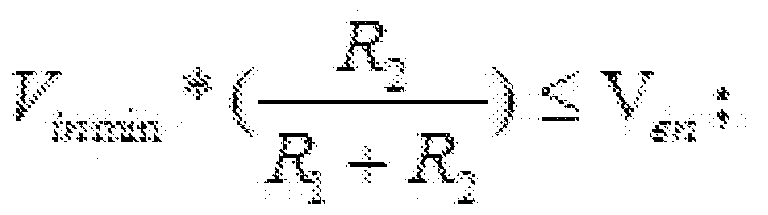

[权利要求 6] 根据权利要求 5所述的 DC-DC电源控制电路, 其特征在于,
所述第一电阻 (2) 和所述第二电阻 (3) 具体为滑动变阻器。
[权利要求 7] 根据权利要求 5所述的 DC-DC电源控制电路, 其特征在于, 所述第一 电阻 (2) 和所述第二电阻 (3) 具体为固定阻值的电阻。
[权利要求 8] 根据权利要求 1至 3任一项所述的 DC-DC电源控制电路, 其特征在于
, 所述 DC-DC电源的型号具体为 MP2315。
[权利要求 9] 一种电子设备, 其特征在于, 包括: DC-DC电源控制电路;
其中, 所述 DC-DC电源控制电路如权利要求 1至 4任一项所述的 DC-D
C电源控制电路;
或者, 所述 DC-DC电源控制电路如权利要求 5至 8任一项所述的 DC-D C电源控制电路。
Priority Applications (6)
| Application Number | Priority Date | Filing Date | Title |
|---|---|---|---|
| US15/323,866 US9899904B2 (en) | 2016-02-18 | 2016-02-18 | DC-DC power supply control circuit and electronic device |
| PCT/CN2016/074048 WO2017139953A1 (zh) | 2016-02-18 | 2016-02-18 | 一种 dc-dc 电源控制电路及电子设备 |
| CN201680000066.8A CN105745807B (zh) | 2016-02-18 | 2016-02-18 | 一种dc-dc电源控制电路及电子设备 |
| PT16818970T PT3232554T (pt) | 2016-02-18 | 2016-02-18 | Circuito dc-dc de controlo de fonte de alimentação e dispositivo eletrónico |
| ES16818970T ES2741300T3 (es) | 2016-02-18 | 2016-02-18 | Circuito de control de fuente de alimentación de CC-CC y dispositivo electrónico |
| EP16818970.2A EP3232554B1 (en) | 2016-02-18 | 2016-02-18 | Dc-dc power source control circuit and electronic device |
Applications Claiming Priority (1)
| Application Number | Priority Date | Filing Date | Title |
|---|---|---|---|
| PCT/CN2016/074048 WO2017139953A1 (zh) | 2016-02-18 | 2016-02-18 | 一种 dc-dc 电源控制电路及电子设备 |
Publications (1)
| Publication Number | Publication Date |
|---|---|
| WO2017139953A1 true WO2017139953A1 (zh) | 2017-08-24 |
Family
ID=56256141
Family Applications (1)
| Application Number | Title | Priority Date | Filing Date |
|---|---|---|---|
| PCT/CN2016/074048 Ceased WO2017139953A1 (zh) | 2016-02-18 | 2016-02-18 | 一种 dc-dc 电源控制电路及电子设备 |
Country Status (6)
| Country | Link |
|---|---|
| US (1) | US9899904B2 (zh) |
| EP (1) | EP3232554B1 (zh) |
| CN (1) | CN105745807B (zh) |
| ES (1) | ES2741300T3 (zh) |
| PT (1) | PT3232554T (zh) |
| WO (1) | WO2017139953A1 (zh) |
Families Citing this family (5)
| Publication number | Priority date | Publication date | Assignee | Title |
|---|---|---|---|---|
| CN107770500A (zh) * | 2017-11-17 | 2018-03-06 | 桂林电子科技大学 | 基于FPGA的Camera Link接口的非标准视频协议传输系统及传输方法 |
| CN112636584B (zh) * | 2020-11-19 | 2022-04-15 | 深圳市捷视飞通科技股份有限公司 | 电子设备、dc-dc电源及其控制电路 |
| CN113300441B (zh) * | 2021-07-28 | 2021-12-10 | 深圳赫兹创新技术有限公司 | 输出电流反复调节的无线充电降额控制方法、装置及系统 |
| CN114156857B (zh) * | 2021-11-29 | 2023-08-01 | 科博达技术股份有限公司 | 可防止错误电压接入的保护电路 |
| CN120613689A (zh) * | 2024-03-07 | 2025-09-09 | 安庆威灵汽车部件有限公司 | 电源电路、电器设备及车辆 |
Citations (6)
| Publication number | Priority date | Publication date | Assignee | Title |
|---|---|---|---|---|
| CN1725616A (zh) * | 2004-07-23 | 2006-01-25 | 上海乐金广电电子有限公司 | 直流电/直流电转换器中低电压阻断电路 |
| CN1797885A (zh) * | 2004-12-24 | 2006-07-05 | 鸿富锦精密工业(深圳)有限公司 | 防止芯片误动作电路 |
| JP2010063304A (ja) * | 2008-09-05 | 2010-03-18 | Sanken Electric Co Ltd | Dc−dcコンバータ |
| CN102594170A (zh) * | 2012-03-09 | 2012-07-18 | 广州金升阳科技有限公司 | 一种宽输入电压电源变换器 |
| CN103227559A (zh) * | 2012-01-31 | 2013-07-31 | 半导体元件工业有限责任公司 | 形成具有断开模式的开关模式电源控制器的方法及其结构 |
| CN204794681U (zh) * | 2015-07-16 | 2015-11-18 | 广州创维平面显示科技有限公司 | 降低掉电时反复重启的dc-dc电路 |
Family Cites Families (18)
| Publication number | Priority date | Publication date | Assignee | Title |
|---|---|---|---|---|
| US3740668A (en) * | 1971-09-20 | 1973-06-19 | Trw Inc | Variable duty-cycle and frequency oscillator circuit |
| US3959716A (en) * | 1975-08-14 | 1976-05-25 | The Bendix Corporation | Wide input range switching voltage regulator |
| US4041546A (en) * | 1976-06-04 | 1977-08-09 | Ncr Corporation | Solenoid driver circuit |
| US4218730A (en) * | 1977-11-09 | 1980-08-19 | Hitachi, Ltd. | Transistor switching apparatus for use in the control of a D.C. load |
| US4859927A (en) * | 1988-10-28 | 1989-08-22 | Fisher Scientific Company | Power supply with improved switching regulator |
| TW230851B (zh) * | 1992-07-03 | 1994-09-21 | Philips Electronics Nv | |
| US5726875A (en) * | 1993-09-27 | 1998-03-10 | Mitsumi Electric Co. Ltd. | AC-DC adapter |
| DE69706625T2 (de) * | 1996-02-12 | 2002-06-27 | Koninklijke Philips Electronics N.V., Eindhoven | Schaltnetzteil mit kompensation für eingangsspannungsänderung |
| US6239585B1 (en) * | 1997-12-08 | 2001-05-29 | Robert N. Buono | Self-oscillating switch-mode DC to DC conversion with current switching threshold hysteresis |
| US20100102789A1 (en) * | 2008-10-27 | 2010-04-29 | Wildcharge, Inc. | Switch-mode power supply method and apparatus using switch-node feedback |
| CN201422106Y (zh) * | 2009-05-27 | 2010-03-10 | 杭州华三通信技术有限公司 | 一种供电端口控制电路 |
| US9564805B2 (en) * | 2011-04-12 | 2017-02-07 | Renesas Electronics Corporation | Voltage generating circuit |
| CN202435015U (zh) * | 2011-12-29 | 2012-09-12 | Tcl集团股份有限公司 | 电源系统 |
| CN202663083U (zh) * | 2012-06-14 | 2013-01-09 | 深圳瑞信视讯技术有限公司 | 直流电高电压输入保护电路 |
| TWI513168B (zh) * | 2012-12-20 | 2015-12-11 | Compal Electronics Inc | 電源轉換裝置 |
| TWI458233B (zh) * | 2013-01-07 | 2014-10-21 | Richtek Technology Corp | Switch power conversion device |
| CN203674978U (zh) * | 2013-11-06 | 2014-06-25 | 艾默生电气公司 | 直流限压电路、包含该直流限压电路的电子设备及温控器 |
| CN104485817A (zh) * | 2014-12-26 | 2015-04-01 | 青岛歌尔声学科技有限公司 | 一种降压电路及电子产品 |
-
2016
- 2016-02-18 US US15/323,866 patent/US9899904B2/en active Active
- 2016-02-18 EP EP16818970.2A patent/EP3232554B1/en active Active
- 2016-02-18 WO PCT/CN2016/074048 patent/WO2017139953A1/zh not_active Ceased
- 2016-02-18 ES ES16818970T patent/ES2741300T3/es active Active
- 2016-02-18 CN CN201680000066.8A patent/CN105745807B/zh active Active
- 2016-02-18 PT PT16818970T patent/PT3232554T/pt unknown
Patent Citations (6)
| Publication number | Priority date | Publication date | Assignee | Title |
|---|---|---|---|---|
| CN1725616A (zh) * | 2004-07-23 | 2006-01-25 | 上海乐金广电电子有限公司 | 直流电/直流电转换器中低电压阻断电路 |
| CN1797885A (zh) * | 2004-12-24 | 2006-07-05 | 鸿富锦精密工业(深圳)有限公司 | 防止芯片误动作电路 |
| JP2010063304A (ja) * | 2008-09-05 | 2010-03-18 | Sanken Electric Co Ltd | Dc−dcコンバータ |
| CN103227559A (zh) * | 2012-01-31 | 2013-07-31 | 半导体元件工业有限责任公司 | 形成具有断开模式的开关模式电源控制器的方法及其结构 |
| CN102594170A (zh) * | 2012-03-09 | 2012-07-18 | 广州金升阳科技有限公司 | 一种宽输入电压电源变换器 |
| CN204794681U (zh) * | 2015-07-16 | 2015-11-18 | 广州创维平面显示科技有限公司 | 降低掉电时反复重启的dc-dc电路 |
Also Published As
| Publication number | Publication date |
|---|---|
| CN105745807B (zh) | 2018-07-24 |
| CN105745807A (zh) | 2016-07-06 |
| EP3232554A1 (en) | 2017-10-18 |
| US20180019659A1 (en) | 2018-01-18 |
| EP3232554B1 (en) | 2019-05-08 |
| EP3232554A4 (en) | 2018-04-11 |
| US9899904B2 (en) | 2018-02-20 |
| PT3232554T (pt) | 2019-08-26 |
| ES2741300T3 (es) | 2020-02-10 |
Similar Documents
| Publication | Publication Date | Title |
|---|---|---|
| WO2017139953A1 (zh) | 一种 dc-dc 电源控制电路及电子设备 | |
| WO2013107320A1 (zh) | 浪涌保护电路 | |
| CN106300247A (zh) | 电压保护电路和系统 | |
| WO2016184026A1 (zh) | 用于缓启动供电回路放电的电路 | |
| CN201656461U (zh) | 突波电流抑制装置及使用其的电子设备 | |
| CN102377162A (zh) | 稳压电路结构 | |
| CN103812484B (zh) | 一种装有控制ic的低噪声fet驱动电路 | |
| CN104348248A (zh) | 启动电路及电子装置 | |
| TWI704739B (zh) | 電源供應裝置 | |
| CN102063143A (zh) | 一种缓变电源管理电路 | |
| CN104104066A (zh) | 一种用于电池反接保护的稳压控制电路 | |
| CN216794851U (zh) | 一种输入过电压保护装置 | |
| CN1909354B (zh) | 功率转换器的启动电路 | |
| US10298180B2 (en) | Control circuit, control method, and electronic device | |
| EP2637307A1 (en) | Mute drive circuit | |
| CN100574030C (zh) | 泄漏电流防护电路 | |
| CN210744739U (zh) | 防反接电路和电子设备 | |
| CN105356433B (zh) | 金属氧化物半导体场效晶体管限流控制电路 | |
| CN103034607B (zh) | 热插拔电路、接口电路及电子设备组件 | |
| CN223599490U (zh) | 一种dc电源输入过压保护电路及电子设备 | |
| CN111404139A (zh) | 一种电源安全保护系统 | |
| WO2014187390A1 (zh) | 一种消除有源钳位拓扑正激关机振荡电路 | |
| CN201041988Y (zh) | 功率转换器的启动电路 | |
| TW201448518A (zh) | 具有兩階式輸出電壓之系統 | |
| TWI351808B (en) | A start up circuit of power converter |
Legal Events
| Date | Code | Title | Description |
|---|---|---|---|
| WWE | Wipo information: entry into national phase |
Ref document number: 15323866 Country of ref document: US |
|
| REEP | Request for entry into the european phase |
Ref document number: 2016818970 Country of ref document: EP |
|
| WWE | Wipo information: entry into national phase |
Ref document number: 2016818970 Country of ref document: EP |
|
| 121 | Ep: the epo has been informed by wipo that ep was designated in this application |
Ref document number: 16818970 Country of ref document: EP Kind code of ref document: A1 |
|
| NENP | Non-entry into the national phase |
Ref country code: DE |