WO2017141346A1 - 多板クラッチ - Google Patents
多板クラッチ Download PDFInfo
- Publication number
- WO2017141346A1 WO2017141346A1 PCT/JP2016/054413 JP2016054413W WO2017141346A1 WO 2017141346 A1 WO2017141346 A1 WO 2017141346A1 JP 2016054413 W JP2016054413 W JP 2016054413W WO 2017141346 A1 WO2017141346 A1 WO 2017141346A1
- Authority
- WO
- WIPO (PCT)
- Prior art keywords
- plate
- shaft
- plate clutch
- bottomed
- plates
- Prior art date
- Legal status (The legal status is an assumption and is not a legal conclusion. Google has not performed a legal analysis and makes no representation as to the accuracy of the status listed.)
- Ceased
Links
Images


Classifications
-
- F—MECHANICAL ENGINEERING; LIGHTING; HEATING; WEAPONS; BLASTING
- F16—ENGINEERING ELEMENTS AND UNITS; GENERAL MEASURES FOR PRODUCING AND MAINTAINING EFFECTIVE FUNCTIONING OF MACHINES OR INSTALLATIONS; THERMAL INSULATION IN GENERAL
- F16D—COUPLINGS FOR TRANSMITTING ROTATION; CLUTCHES; BRAKES
- F16D13/00—Friction clutches
- F16D13/58—Details
- F16D13/60—Clutching elements
- F16D13/62—Clutch-bands; Clutch shoes; Clutch-drums
-
- F—MECHANICAL ENGINEERING; LIGHTING; HEATING; WEAPONS; BLASTING
- F16—ENGINEERING ELEMENTS AND UNITS; GENERAL MEASURES FOR PRODUCING AND MAINTAINING EFFECTIVE FUNCTIONING OF MACHINES OR INSTALLATIONS; THERMAL INSULATION IN GENERAL
- F16D—COUPLINGS FOR TRANSMITTING ROTATION; CLUTCHES; BRAKES
- F16D13/00—Friction clutches
- F16D13/58—Details
- F16D13/60—Clutching elements
- F16D13/64—Clutch-plates; Clutch-lamellae
- F16D13/648—Clutch-plates; Clutch-lamellae for clutches with multiple lamellae
-
- F—MECHANICAL ENGINEERING; LIGHTING; HEATING; WEAPONS; BLASTING
- F16—ENGINEERING ELEMENTS AND UNITS; GENERAL MEASURES FOR PRODUCING AND MAINTAINING EFFECTIVE FUNCTIONING OF MACHINES OR INSTALLATIONS; THERMAL INSULATION IN GENERAL
- F16D—COUPLINGS FOR TRANSMITTING ROTATION; CLUTCHES; BRAKES
- F16D13/00—Friction clutches
- F16D13/58—Details
- F16D13/74—Features relating to lubrication
-
- F—MECHANICAL ENGINEERING; LIGHTING; HEATING; WEAPONS; BLASTING
- F16—ENGINEERING ELEMENTS AND UNITS; GENERAL MEASURES FOR PRODUCING AND MAINTAINING EFFECTIVE FUNCTIONING OF MACHINES OR INSTALLATIONS; THERMAL INSULATION IN GENERAL
- F16D—COUPLINGS FOR TRANSMITTING ROTATION; CLUTCHES; BRAKES
- F16D69/00—Friction linings; Attachment thereof; Selection of coacting friction substances or surfaces
- F16D2069/004—Profiled friction surfaces, e.g. grooves, dimples
-
- F—MECHANICAL ENGINEERING; LIGHTING; HEATING; WEAPONS; BLASTING
- F16—ENGINEERING ELEMENTS AND UNITS; GENERAL MEASURES FOR PRODUCING AND MAINTAINING EFFECTIVE FUNCTIONING OF MACHINES OR INSTALLATIONS; THERMAL INSULATION IN GENERAL
- F16D—COUPLINGS FOR TRANSMITTING ROTATION; CLUTCHES; BRAKES
- F16D2200/00—Materials; Production methods therefor
- F16D2200/0034—Materials; Production methods therefor non-metallic
- F16D2200/0052—Carbon
-
- F—MECHANICAL ENGINEERING; LIGHTING; HEATING; WEAPONS; BLASTING
- F16—ENGINEERING ELEMENTS AND UNITS; GENERAL MEASURES FOR PRODUCING AND MAINTAINING EFFECTIVE FUNCTIONING OF MACHINES OR INSTALLATIONS; THERMAL INSULATION IN GENERAL
- F16D—COUPLINGS FOR TRANSMITTING ROTATION; CLUTCHES; BRAKES
- F16D2200/00—Materials; Production methods therefor
- F16D2200/006—Materials; Production methods therefor containing fibres or particles
Definitions
- the present disclosure relates to a multi-plate clutch including a friction material made of carbon fiber, and more particularly, to a wet multi-plate clutch including a friction material made of carbon fiber and interwoven with warp and weft.
- Some devices that make up the drive train of an automobile often use multi-plate clutches to regulate torque transmission or limit differentials. These devices are filled with lubricating oil, and usually the multi-plate clutch is operated in a wet type using this lubricating oil. When a sufficient fastening force is applied, the multi-plate clutch exerts a large braking force, but the lubricating oil promotes sliding between the clutch plates, so when the fastening force is reduced, the braking force is reduced according to the degree. Thus, torque transmission can be continuously adjusted, or the degree of differential can be adjusted.
- a friction material is usually adhered to one group of plates of the multi-plate clutch.
- a paper friction material made of pulp or synthetic fibers, and the pores between the fibers contribute to maintaining lubricating properties by retaining lubricating oil.
- carbon powder may be supported in such holes.
- the present inventors found that the wear of the warp was remarkable as compared with the weft.
- the uneven wear is disadvantageous for the characteristics of the multi-plate clutch, and for example, seizure is likely to occur.
- the inventors of the present invention have investigated the cause of the remarkable problem of warp wear, and have therefore come up with the following solution.
- a multi-plate clutch used in combination with a drive mechanism capable of exerting a pressing force in a direction along an axis includes at least one core plate coupled to a first rotating body rotatable around the axis, and the core plate And a second rotating body that is alternately arranged in the direction of the shaft and is rotatable around the shaft, and receives the pressing force from the drive mechanism and moves in the direction along the shaft to move the core.
- reaction plates that frictionally contact the plate to brake the first rotating body against the second rotating body, and each core plate fixed to a surface that contacts the reaction plate, respectively,
- friction materials including warps and wefts made of fibers and knitted so as to be orthogonal to each other, and a surface in contact with the core plate in each reaction plate And a plurality of bottomed grooves which are respectively formed, the.
- FIG. 1 is a longitudinal sectional view of a final drive provided with a multi-plate clutch.
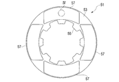
- FIG. 2 is a plan view of a core plate provided with a friction material.
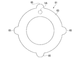
- FIG. 3 is a plan view of a reaction plate having a bottomed groove.
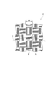
- FIG. 4 is a schematic plan view of the surface of the friction material.
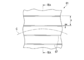
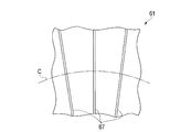
- FIG. 5A is a schematic plan view of the surface of the reaction plate according to the first embodiment.
- FIG. 5B is a schematic plan view of the surface of the reaction plate according to the second embodiment.
- FIG. 5C is a schematic plan view of the surface of the reaction plate according to the third embodiment.
- FIG. 5D is a schematic plan view of the surface of the reaction plate according to the fourth embodiment.
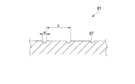
- FIG. 6A is a cross-sectional view of a reaction plate according to one example.
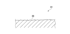
- FIG. 6B is a cross-sectional view of a reaction plate according to another example.
- F represents the front of the vehicle
- A represents the rear
- R represents the right
- L represents the left.
- the axis means the central axis of the clutch unless otherwise specified.
- the front, rear, left and right may be distinguished, but these are merely for convenience of explanation and do not limit the embodiment.
- the multi-plate clutch according to the present embodiment can be suitably used for an apparatus constituting a drive train such as a transmission, a torque manager, or a limited slip differential (LSD), but of course is not limited thereto.
- a drive train such as a transmission, a torque manager, or a limited slip differential (LSD), but of course is not limited thereto.
- LSD limited slip differential
- the final drive 1 illustrated in FIG. 1 is an example in which a multi-plate clutch is used.
- the final drive 1 differentially distributes the torque transmitted from the propeller shaft to the pair of rear axles.
- the casing 10 defines a single chamber 15 therein, and includes a differential gear set 3, a multi-plate clutch 5, and a drive mechanism 7 for controlling the clutch.
- the input shaft 21 is coupled to the propeller shaft to receive torque
- the differential gear set 3 is interposed to output torque from both sides to the pair of rear axles.
- the multi-plate clutch 5 limits the differential of the differential gear set 3.
- the input shaft 21 transmits the received torque to the differential gear set 3 through a gear.
- the differential gear set 3 generally includes a case 33 that rotates around an axis X by an input torque, and a plurality of pinion gears 35 that rotate with the case 33, and a pair of side gears 37 and 39 that mesh with the pinion gear 35, respectively. , Output torque differentially.
- Each side gear 37, 39 is coupled to the right and left rear axles.
- Lubricating oil is injected into the chamber 15, and the sealing member 13 liquid-tightly seals the periphery of the input shaft 21 and the periphery of the axle so that the lubricating oil is sealed inside.
- the lubricating oil circulates in the chamber 15 with the rotation of the case 33 and each gear, and lubricates each element including the multi-plate clutch 5.
- the multi-plate clutch 5 and the drive mechanism 7 are coaxially supported by the differential gear set 3 and are adjacent to each other in the axial direction.
- the multi-plate clutch 5 can rotate around the axis X, but the drive mechanism 7 is prevented from rotating, and the drive mechanism 7 exerts a pressing force on the multi-plate clutch 5 in the direction along the axis X.
- the multi-plate clutch 5 includes a plurality of clutch plates 51 and 61, and the inner clutch plates 51 and the outer clutch plates 61 are alternately arranged.
- the inner clutch plate 51 is drivingly connected to the side gear 39
- the outer clutch plate 61 is drivingly connected to the case 33.
- the clutch plates 51 and 61 come into contact with each other, and the side gear 39 is braked against the case 33 by frictionally braking each other. That is, the multi-plate clutch 5 limits the differential of the differential gear set 3.
- the inner clutch plate 51 is a core plate provided with a friction material
- the outer clutch plate 61 is a reaction plate, but this relationship may be reversed.
- the inner clutch plate 51 is a relatively thin plate made of a rigid material such as low carbon steel, and the whole is generally annular.
- the center of the ring is substantially coincident with the axis X.
- a plurality of keys 55 project radially inward from the inner periphery of the ring, and the keys 55 engage with splines provided in the side gear 39. Accordingly, the inner clutch plate 51 is drivingly coupled to the side gear 39 and is movable in the direction along the axis X.
- the inner clutch plate 51 normally has both surfaces 53 facing the outer clutch plate 61, and one or more friction plates 57 are fixed to these surfaces 53 by adhesion.
- Each friction plate 57 may be an integral annular shape, or a plurality of friction plates 57 may be arranged on the surface 53 in an annular shape as illustrated. Since the friction plates 57 slightly protrude from the both surfaces 53 of the inner clutch plate 51, it is these friction plates 57 that directly contact the outer clutch plate 61.
- each friction plate 57 is made of carbon fiber.
- the warps F1 made of carbon fibers are bundled in parallel in the order of several tens to several hundreds to form a fiber bundle.
- the weft F2 made of carbon fibers also forms a fiber bundle.
- These fiber bundles are knitted so as to be orthogonal to each other, thereby forming a friction plate 57.
- the width wb of these fiber bundles is, for example, not less than 1 mm and not more than 10 mm.
- the friction plate 57 is also fixed to the inner clutch plate 51 so as to face a specific direction.
- the warp F1 is parallel to the radial direction with respect to the axis X and the weft F2 is parallel to the circumferential direction C at the center of the friction plate 57 serving as a reference point.
- the weft F2 forms an angle of, for example, 0 to 45 degrees with respect to the circumferential direction C and the warp F1
- an angle of 45 to 90 degrees is formed with respect to the direction C.
- the reference point is not limited to the center of the friction plate 57 but may be, for example, an end.
- the outer clutch plate 61 is also a relatively thin plate made of a rigid material such as low carbon steel, and the whole is generally annular.
- the center of the ring is substantially coincident with the axis X.
- a plurality of tabs 65 project radially outward from the outer periphery of the ring, and the tabs 65 engage with key grooves provided in the case 33. Accordingly, the outer clutch plate 61 is drivingly coupled to the case 33 and is movable in the direction along the axis X.
- the gaps between the warps F1 and the wefts F2 can hold the lubricating oil, and when the outer clutch plate 61 contacts the friction plate 57, the lubricating oil is supplied to the interface and lubricates the interface. Since the outer clutch plate 61 moves relative to the friction plate 57 only in the circumferential direction C, the weft F2 parallel to the outer clutch plate 61 can continuously supply the lubricating oil. F1 cannot hold the lubricating oil very quickly. As a result, the warp F1 is worn out by causing local oil film breakage.
- the outer clutch plate 61 includes means for supplying lubricating oil to the warp F1.
- Such means is, for example, a bottomed groove 67 such as a U-groove, V-groove, rectangular groove, or free-form groove formed on the surface 63 of the outer clutch plate 61 that contacts the inner clutch plate 51.
- the bottomed groove 67 can hold the lubricating oil, and can hold the lubricating oil in a larger amount than the gap between the warps F1 and the wefts F2.
- the bottomed groove 67 supplies lubricating oil to the interface by moving relative to the outer clutch plate 61.
- the bottomed groove 67 is a linear groove that runs in parallel on the entire surface 63 of the outer clutch plate 61.
- the bottomed groove 67 is parallel to the warp yarn F1 (at right angles to the weft yarn F2) at least twice per rotation, and also makes one rotation. Is twice perpendicular to the warp F1 (parallel to the weft F2).
- the lubricating oil is exchanged between the warp F1, the weft F2, and the bottomed groove 67, and the warp F1 can be supplied with the lubricating oil. Therefore, the friction plate 57 is unlikely to cause local oil film breakage and can prevent uneven wear.
- Such a bottomed groove 67 can be formed by any of grinding, turning, or machining.
- a grinding wheel made of relatively coarse abrasive grains is rotated, and the outer clutch plate 61 is passed in one direction under the grinding wheel so that parallel straight bottomed grooves 67 are formed. Can be formed. Grinding is advantageous in terms of high manufacturing efficiency.
- the adjacent bottomed grooves 67 are usually in contact with each other, and the surface 63 of the outer clutch plate 61 is a rough surface having a texture 69.
- adjacent bottomed grooves 67 may be separated by a certain amount. Machining may be suitable for forming such a bottomed groove 67.
- the bottomed groove 67 has a depth of about several ⁇ m, the above-described effect can be obtained. However, if the bottomed groove 67 is too shallow, the effect is limited, and thus the depth is preferably 1 ⁇ m or more. Or arithmetic average roughness Ra is 0.4 micrometer or more and 1.3 micrometers or less. Further, the maximum height Ry is 4.5 ⁇ m or more and 13.0 ⁇ m or less. Further, the effect is enhanced when the groove is dense, but the effect is limited when the width of the groove is reduced. Therefore, the pitch p or the width w of the bottomed groove 67 is preferably 5 ⁇ m or more and 2 mm or less, more preferably It is 5 ⁇ m or more and 100 ⁇ m or less.
- the pitch p or width w of the bottomed groove 67 and the width wb of the fiber bundle in the friction plate 57 can be arbitrarily selected from a preferable range. Therefore, the pitch p or the width w of the bottomed groove 67 may be determined as a relative value with respect to the width wb of the fiber bundle. The coarser the distribution of the bottomed grooves 67 as compared with the width of the fiber bundle, the less frequently the fiber bundle is supplied with lubricating oil, and the denser the density, the higher the effect can be expected. Therefore, for example, the pitch p or width w of the bottomed groove can be made smaller than the width wb of the fiber bundle. In particular, the pitch p or the width w can be defined by paying attention to the width of the fiber bundle of the warp F1.
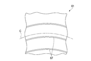
- the bottomed groove 67 may also be concentric arcs or circles along the circumferential direction C as shown in FIG. 5B.
- the bottomed groove 67 is always substantially perpendicular to the warp yarn F1 and substantially parallel to the weft F2. However, since the lubricating oil is always supplied to the warp yarn F1 through the bottomed groove 67, local wear is similarly prevented. be able to.
- the center of the arc or circle may coincide with the axis X, or may deviate from the axis X to some extent.
- the outer clutch plate 61 rotates relative to the friction plate 57, if the arc or circle is concentric with the axis X, the bottomed groove 67 always runs in the same position with respect to the friction plate 57. In this case, the vehicle runs while changing its position with respect to the friction plate 57. The latter is more advantageous for spreading the lubricant evenly across the interface.
- the arcuate or circular bottomed groove 67 can be easily formed by turning. Turning is also advantageous because of its high production efficiency.
- the bottomed groove 67 may be composed of a straight line or a curved line that intersects with each other at a certain angle, as shown in FIG. 5C.
- the bottomed groove 67 may have a radial shape or a spiral shape extending from an appropriately selected center.
- the center of the radiation or vortex may coincide with the axis X or may deviate from the axis X to some extent.
- a multi-plate clutch capable of preventing local wear is provided.
Landscapes
- Engineering & Computer Science (AREA)
- General Engineering & Computer Science (AREA)
- Mechanical Engineering (AREA)
- Mechanical Operated Clutches (AREA)
- Braking Arrangements (AREA)
Abstract
軸に沿う方向に押圧力を行使可能な駆動機構と組み合わせて使用される多板クラッチは前記軸の周りに回転可能な第1の回転体にそれぞれ結合した一以上のコアプレートと、前記コアプレートと前記軸の方向に交互に配列され、前記軸の周りに回転可能な第2の回転体にそれぞれ結合し、前記駆動機構から前記押圧力を受けて前記軸に沿う方向に移動して前記コアプレートに摩擦的に接して前記第1の回転体を前記第2の回転体に対して制動する一以上のリアクションプレートと、前記各コアプレートにおいて前記リアクションプレートに接する面にそれぞれ固定され、それぞれ炭素繊維よりなり互いに直交するように編まれた経糸と緯糸とを含む、一以上の摩擦材と、前記各リアクションプレートにおいて前記コアプレートに接する面にそれぞれ形成された複数の有底溝と、を備える。
Description
本開示は、炭素繊維よりなる摩擦材を含む多板クラッチに関し、特にそれぞれ炭素繊維よりなり互いに織り合わされた経糸と緯糸よりなる摩擦材を含む湿式多板クラッチに関する。
自動車のドライブトレインを構成する幾つかの装置には、トルクの伝達を調節し、あるいは差動を制限する目的で、しばしば多板クラッチが利用される。これらの装置には潤滑油が封入されており、通常、この潤滑油を利用して多板クラッチは湿式の形式で運用される。十分な締結力が付与されたときには多板クラッチは大きな制動力を発揮するが、潤滑油はクラッチプレート間の滑動を促すので、締結力が減じられたときにはその程度に応じて制動力が減じられ、以ってトルクの伝達を連続的に調節することができ、あるいは差動の程度を調節することができる。
潤滑油が介在するとはいえ、頻繁にクラッチプレート間に滑りが発生するので、各クラッチプレートの磨耗は避けられない。磨耗粉は潤滑油の全体に広がり、これを劣化させる。また潤滑油に懸濁された磨耗粉は、装置の他の構成要素に溜り、その動作を妨げかねない。
クラッチの焼き付きを防ぐ等の目的のため、通常、多板クラッチの一方の群のプレートには摩擦材が接着されている。一般的に利用されるのは、パルプあるいは合成繊維よりなるペーパー摩擦材であり、繊維間の空孔は潤滑油を保持して潤滑性を維持するのに寄与する。さらに減摩材として、カーボン粉末をかかる空孔に担持せしめる場合もある。特許文献1は、関連する技術を開示する。
炭素繊維よりなる摩擦材の磨耗特性について検討したところ、本発明者らは、緯糸に比して経糸の磨耗が著しいことを見出した。磨耗の偏りは多板クラッチの諸特性に不利であり、例えば焼き付きが起こりやすくなる。本発明者らは、経糸の磨耗が著しい問題の原因を究明し、以って以下の解決手段に想到した。
軸に沿う方向に押圧力を行使可能な駆動機構と組み合わせて使用される多板クラッチは前記軸の周りに回転可能な第1の回転体にそれぞれ結合した一以上のコアプレートと、前記コアプレートと前記軸の方向に交互に配列され、前記軸の周りに回転可能な第2の回転体にそれぞれ結合し、前記駆動機構から前記押圧力を受けて前記軸に沿う方向に移動して前記コアプレートに摩擦的に接して前記第1の回転体を前記第2の回転体に対して制動する一以上のリアクションプレートと、前記各コアプレートにおいて前記リアクションプレートに接する面にそれぞれ固定され、それぞれ炭素繊維よりなり互いに直交するように編まれた経糸と緯糸とを含む、一以上の摩擦材と、前記各リアクションプレートにおいて前記コアプレートに接する面にそれぞれ形成された複数の有底溝と、を備える。
図1ないし6Bを参照して以下に幾つかの例示的な実施形態を説明する。各図において、Fは車両の前方を、Aは後方を、Rは右方を、そしてLは左方を表す。
以下の説明および請求の範囲を通じて、特段の説明がなければ、軸はクラッチの中心軸の意味である。また前後左右を区別することがあるが、これらは説明の便宜のために過ぎず、実施形態を制限するものではない。
本実施形態による多板クラッチは、トランスミッション、トルクマネージャあるいはリミテッドスリップデフ(LSD)のごとき、ドライブトレインを構成する装置に好適に利用できるが、もちろんこれらに限られない。
図1に例示したファイナルドライブ1は、多板クラッチが利用される一例である。ファイナルドライブ1は、プロペラシャフトから伝達されたトルクを一対のリアアクスルに差動的に分配する。そのケーシング10は、その内部に単一のチャンバ15を画し、かかるチャンバ15内に、デファレンシャルギア組3、多板クラッチ5、およびクラッチを制御する駆動機構7を内包する。前方において入力シャフト21がプロペラシャフトと結合してトルクを受容し、デファレンシャルギア組3が介在して両側から一対のリアアクスルへトルクを出力する。多板クラッチ5はデファレンシャルギア組3の差動を制限する。
入力シャフト21は、受容したトルクをギアを介してデファレンシャルギア組3へ伝達する。デファレンシャルギア組3は、概して、入力されたトルクにより軸X周りに回転するケース33と、これと共に回転する複数のピニオンギア35とを備え、ピニオンギア35にそれぞれ噛合した一対のサイドギア37,39へ、トルクを差動的に出力する。各サイドギア37,39は右および左リアアクスルに結合する。
チャンバ15には潤滑油が注入され、またシール部材13が入力シャフト21周りやアクスル周りを液密的に封ずることにより、潤滑油が内部に封じられる。潤滑油は、ケース33や各ギアの回転に伴いチャンバ15内を循環し、多板クラッチ5を含めた各要素を潤滑する。
多板クラッチ5と駆動機構7は、デファレンシャルギア組3に同軸に支持され、互いに軸方向に隣り合っている。多板クラッチ5は軸X周りに回転可能だが駆動機構7は回り止めされており、また駆動機構7は軸Xに沿う方向に多板クラッチ5に押圧力を及ぼす。
多板クラッチ5は、複数のクラッチ板51,61を備え、インナクラッチ板51とアウタクラッチ板61とは交互に配列されている。インナクラッチ板51はサイドギア39に駆動的に結合し、アウタクラッチ板61はケース33に駆動的に結合している。駆動機構7より押圧力が作用したときには、クラッチ板51,61が互いに接し、さらに摩擦的に互いを制動することにより、サイドギア39をケース33に対して制動する。すなわち多板クラッチ5はデファレンシャルギア組3の差動を制限する。
以下に説明する例においては、インナクラッチ板51は摩擦材を備えたコアプレートであり、アウタクラッチ板61はリアクションプレートであるが、この関係は逆であってもよい。
図2を参照するに、インナクラッチ板51は、低炭素鋼のごとき剛直な素材よりなる比較的に薄い板であって、その全体は概して円環状である。円環の中心は、軸Xに略一致している。円環の内周からは複数のキー55が径方向に内方に突出しており、かかるキー55はサイドギア39が備えるスプラインに係合する。以ってインナクラッチ板51はサイドギア39に駆動的に結合し、また軸Xに沿う方向には移動可能である。
インナクラッチ板51の、通常には両面は、アウタクラッチ板61に対向する面53であって、これらの面53にはそれぞれ一以上の摩擦板57が接着により固定されている。各摩擦板57は一体の円環状であってもよく、あるいは図示のごとく複数枚の摩擦板57が円環状に面53上に並べられていてもよい。摩擦板57はインナクラッチ板51の両面53より僅かに突出しているので、アウタクラッチ板61に直接に接するのはこれらの摩擦板57である。
図4を参照するに、摩擦板57はそれぞれ炭素繊維よりなる。炭素繊維よりなる経糸F1は数十本から数百本の程度で平行に束ねられて繊維束をなし、同様に炭素繊維よりなる緯糸F2も繊維束をなす。これらの繊維束は互いに直交するように編まれ、以って摩擦板57が構成されている。これらの繊維束の幅wbは、それぞれ例えば1mm以上10mm以下である。
摩擦板57はまた、特定の方向になるように向けられてインナクラッチ板51に固定される。すなわち、図4の例では、基準点となる摩擦板57の中央において、経糸F1は軸Xに関して径方向に平行であり、緯糸F2は周方向Cに平行である。ただし基準点から周方向Cに離れるに従ってそれぞれ平行からずれてくるので、摩擦板57の全体を見れば、緯糸F2は周方向Cに対して例えば0から45度の角をなし、経糸F1は周方向Cに対して例えば45から90度の角をなす。また基準点は摩擦板57の中央に限らず例えば端であることもありうる。
図3を参照するに、アウタクラッチ板61も低炭素鋼のごとき剛直な素材よりなる比較的に薄い板であって、その全体は概して円環状である。円環の中心は、軸Xに略一致している。円環の外周からは複数のタブ65が径方向に外方に突出しており、かかるタブ65はケース33が備えるキー溝に係合する。以ってアウタクラッチ板61はケース33に駆動的に結合し、また軸Xに沿う方向には移動可能である。
経糸F1間や緯糸F2間の隙間は、潤滑油を保持することができ、アウタクラッチ板61が摩擦板57に接したときに、かかる潤滑油は界面に供給されて界面を潤滑する。アウタクラッチ板61は摩擦板57に対して周方向Cにのみ相対的に移動するので、これに平行な緯糸F2は潤滑油を連続的に供給し続けることができるが、これに略直交する経糸F1は極めて速やかに潤滑油を保持できなくなる。その結果、経糸F1は局所的な油膜切れを起こして磨耗してしまう。
上述のごとき問題を克服するべく、アウタクラッチ板61は経糸F1に潤滑油を供給する手段を備える。かかる手段は、例えば、アウタクラッチ板61においてインナクラッチ板51に接する面63にそれぞれ形成された、U溝、V溝、矩形溝、あるいは自由形状溝のごとき有底溝67である。有底溝67は潤滑油を保持することができ、且つ、経糸F1間や緯糸F2間の隙間よりも多量に潤滑油を保持することができる。有底溝67は、アウタクラッチ板61に対して相対運動することにより、界面に潤滑油を供給する。
図5Aを参照するに、一例によれば、有底溝67はアウタクラッチ板61の面63の全体を平行に走る直線状の溝である。アウタクラッチ板61がインナクラッチ板51に対して周方向Cに相対運動するとき、少なくとも1回転につき2回、有底溝67は経糸F1に平行になり(緯糸F2に直交する)、また1回転につき2回、経糸F1に直交する(緯糸F2に平行になる)。かかる過程において、経糸F1、緯糸F2、および有底溝67の間で潤滑油が交換され、経糸F1は潤滑油の供給を受けることができる。それゆえ摩擦板57は局所的な油膜切れを起こしにくく、偏った磨耗を防ぐことができる。
このような有底溝67は、研削、旋削、あるいは機械加工の何れによっても形成することができる。例えば研削によれば、比較的に粗い砥粒よりなる砥石車を回転させておき、かかる砥石車下にアウタクラッチ板61を一方向にくぐらせることにより、平行な直線状の有底溝67を形成することができる。研削は製作効率が高い点で有利である。かかる方法によれば、断面を表す図6Bに示すごとく、通常には隣接する有底溝67同士は接し、アウタクラッチ板61の面63はテクスチャ69を有する粗面となる。あるいは図6Aに示すごとく、隣接する有底溝67は一定の程度離れていてもよい。そのような有底溝67を形成するには、機械加工が適しているだろう。
有底溝67は数μmの程度の深さを持てば上述の効果を奏しうるが、浅すぎれば効果が限定的であるので、好ましくは深さ1μm以上である。あるいは算術平均粗さRaが0.4μm以上1.3μm以下である。さらにあるいは最大高さRyが4.5μm以上13.0μm以下である。また溝が密であるほうが効果が高まるが溝の幅が小さくなれば効果が限定的となるので、有底溝67のピッチpないし幅wは、好ましくは5μm以上2mm以下であり、より好ましくは5μm以上100μm以下である。
既に述べた通り、有底溝67のピッチpないし幅wも、摩擦板57における繊維束の幅wbも、好ましい範囲から任意にその値を選択することができる。そこで有底溝67のピッチpないし幅wを、繊維束の幅wbに対して相対的な値として決めてもよい。繊維束の幅に比して有底溝67の分布が粗である程、繊維束は潤滑油を供給される頻度が減り、密であるほどその効果が期待できる。そこで例えば有底溝のピッチpないし幅wは繊維束の幅wbより小とすることができる。特に経糸F1の繊維束の幅に注目してピッチpないし幅wを規定することができる。
有底溝67は、また、図5Bに示すごとく周方向Cに沿った互いに同心な円弧状ないし円状であってもよい。かかる有底溝67は常に経糸F1に略直交し、緯糸F2に略平行であるが、有底溝67を介して経糸F1に潤滑油が常に供給されるので、同様に局所的な磨耗を防ぐことができる。
かかる円弧ないし円の中心は、軸Xに一致していてもよく、あるいは軸Xからある程度ずれていてもよい。アウタクラッチ板61が摩擦板57に対して相対的に回転するとき、円弧ないし円が軸Xと同心な場合は、有底溝67は摩擦板57に対して常に同一の位置を走るが、異心の場合は、摩擦板57に対して位置を変えながら走る。潤滑油を界面にまんべんなく行き渡らせるには後者のほうが有利である。円弧状ないし円状の有底溝67は、旋削により容易に形成することができる。旋削も製作効率が高い点で有利である。
あるいは有底溝67は、図5Cに示すごとく、互いに一定の角度をもって交わる直線ないし曲線よりなるものであってもよい。さらにまた有底溝67は、図5Dに示すごとく、適宜に選択された中心から延びる放射状ないし渦状であってもよい。放射ないし渦の中心は、軸Xに一致していてもよく、あるいは軸Xからある程度ずれていてもよい。これらは製作のためのコストが高くなる点では不利だが、遠心力を利用して潤滑油の循環を促すことができる点では有利である。
好適な実施形態により本発明を説明したが、本発明は上記実施形態に限定されるものではない。上記開示内容に基づき、当該技術分野の通常の技術を有する者が、実施形態の修正ないし変形により本発明を実施することが可能である。
局部的な磨耗を防ぐことができる多板クラッチが提供される。
Claims (8)
- 軸に沿う方向に押圧力を行使可能な駆動機構と組み合わせて使用される多板クラッチであって、
前記軸の周りに回転可能な第1の回転体にそれぞれ結合した一以上のコアプレートと、
前記コアプレートと前記軸の方向に交互に配列され、前記軸の周りに回転可能な第2の回転体にそれぞれ結合し、前記駆動機構から前記押圧力を受けて前記軸に沿う方向に移動して前記コアプレートに摩擦的に接して前記第1の回転体を前記第2の回転体に対して制動する一以上のリアクションプレートと、
前記各コアプレートにおいて前記リアクションプレートに接する面にそれぞれ固定され、それぞれ炭素繊維よりなり互いに直交するように編まれた経糸束と緯糸束とを含む、一以上の摩擦材と、
前記各リアクションプレートにおいて前記コアプレートに接する面にそれぞれ形成された複数の有底溝と、
を備えた多板クラッチ。 - 請求項1の多板クラッチであって、前記有底溝の間のピッチは前記経糸束の幅より小である、多板クラッチ。
- 請求項1の多板クラッチであって、前記有底溝は前記コアプレートに接する前記面の全体において互いに平行な直線である、多板クラッチ。
- 請求項1の多板クラッチであって、前記有底溝は互いに同心な円弧ないし円である、多板クラッチ。
- 請求項1の多板クラッチであって、前記有底溝は前記軸に関して径方向に向けられた放射線である、多板クラッチ。
- 請求項1ないし5の何れか1項の多板クラッチであって、前記有底溝は深さ1μm以上である、多板クラッチ。
- 請求項1ないし5の何れか1項の多板クラッチであって、前記有底溝は幅5μm以上2mm以下である、多板クラッチ。
- 請求項1ないし5の何れか1項の多板クラッチであって、前記軸に関して周方向に対して前記経糸が45から90度の角をなすべく、前記摩擦材は向けられている、多板クラッチ。
Priority Applications (5)
| Application Number | Priority Date | Filing Date | Title |
|---|---|---|---|
| PCT/JP2016/054413 WO2017141346A1 (ja) | 2016-02-16 | 2016-02-16 | 多板クラッチ |
| EP16890488.6A EP3418598A4 (en) | 2016-02-16 | 2016-02-16 | MORE PLATE CLUTCH |
| CN201680058786.XA CN108138860B (zh) | 2016-02-16 | 2016-02-16 | 多片离合器 |
| JP2017567853A JP6535111B2 (ja) | 2016-02-16 | 2016-02-16 | 多板クラッチ |
| US15/947,904 US10480588B2 (en) | 2016-02-16 | 2018-04-09 | Multi-plate clutch |
Applications Claiming Priority (1)
| Application Number | Priority Date | Filing Date | Title |
|---|---|---|---|
| PCT/JP2016/054413 WO2017141346A1 (ja) | 2016-02-16 | 2016-02-16 | 多板クラッチ |
Related Child Applications (1)
| Application Number | Title | Priority Date | Filing Date |
|---|---|---|---|
| US15/947,904 Continuation US10480588B2 (en) | 2016-02-16 | 2018-04-09 | Multi-plate clutch |
Publications (1)
| Publication Number | Publication Date |
|---|---|
| WO2017141346A1 true WO2017141346A1 (ja) | 2017-08-24 |
Family
ID=59625685
Family Applications (1)
| Application Number | Title | Priority Date | Filing Date |
|---|---|---|---|
| PCT/JP2016/054413 Ceased WO2017141346A1 (ja) | 2016-02-16 | 2016-02-16 | 多板クラッチ |
Country Status (5)
| Country | Link |
|---|---|
| US (1) | US10480588B2 (ja) |
| EP (1) | EP3418598A4 (ja) |
| JP (1) | JP6535111B2 (ja) |
| CN (1) | CN108138860B (ja) |
| WO (1) | WO2017141346A1 (ja) |
Families Citing this family (3)
| Publication number | Priority date | Publication date | Assignee | Title |
|---|---|---|---|---|
| DE102017208529A1 (de) * | 2017-05-19 | 2018-11-22 | Continental Teves Ag & Co. Ohg | Bremsscheibe mit einem Reibring aus PMMC Werkstoff |
| JP6677423B2 (ja) * | 2018-09-21 | 2020-04-08 | 株式会社エフ・シー・シー | 湿式摩擦プレートの製造方法、湿式摩擦プレートおよび同湿式摩擦プレートを備えた湿式多板クラッチ装置 |
| CN113146481B (zh) * | 2021-05-11 | 2026-02-24 | 长春理工大学 | 一种离合器磨粒流精密抛光设备 |
Citations (6)
| Publication number | Priority date | Publication date | Assignee | Title |
|---|---|---|---|---|
| JPH11201183A (ja) | 1998-01-14 | 1999-07-27 | Tochigi Fuji Ind Co Ltd | 摩擦クラッチ及びこの摩擦クラッチにおける摩擦材ライニングの固着方法 |
| JP2002195291A (ja) * | 2000-12-26 | 2002-07-10 | Tokai Carbon Co Ltd | 湿式クラッチ装置 |
| JP2003090371A (ja) * | 2001-09-18 | 2003-03-28 | Tokai Carbon Co Ltd | 炭素系湿式摩擦材 |
| JP2003240034A (ja) * | 2002-02-20 | 2003-08-27 | Honda Motor Co Ltd | 湿式摩擦係合装置用摩擦部材 |
| JP2005214284A (ja) * | 2004-01-29 | 2005-08-11 | Kito Corp | 巻き上げ機 |
| JP2008309317A (ja) * | 2007-06-18 | 2008-12-25 | Aisin Aw Co Ltd | 発進装置 |
Family Cites Families (14)
| Publication number | Priority date | Publication date | Assignee | Title |
|---|---|---|---|---|
| US3365041A (en) * | 1965-10-21 | 1968-01-23 | Raybestos Manhattan Inc | Clutch facing |
| JP2580706Y2 (ja) * | 1986-11-04 | 1998-09-17 | 株式会社ダイナックス | 湿式摩擦板 |
| JPH06185541A (ja) * | 1992-12-17 | 1994-07-05 | Nsk Warner Kk | 湿式多板摩擦係合装置 |
| US5615758A (en) * | 1994-09-30 | 1997-04-01 | Nels; Terry E. | Fabric arrangement and method for controlling fluid flow |
| DE19957511A1 (de) * | 1999-11-30 | 2001-06-21 | Borg Warner Automotive Gmbh | Lamelle für ein Kraftübertragungsaggregat, zum Beispiel für eine Schaltkupplung |
| DE10334881A1 (de) * | 2003-07-29 | 2005-03-03 | Sgl Carbon Ag | Verfahren zur Herstellung eines auf einem flächigen Carbonfaser-Gewebe basierenden Reibmaterials für Nassreibelemente und nach dem Verfahren hergestelltes Reibmaterial |
| JP2005308183A (ja) * | 2004-04-26 | 2005-11-04 | Nsk Ltd | 湿式多板摩擦係合装置 |
| DE102006045456B4 (de) * | 2006-09-26 | 2014-07-24 | Borgwarner Inc. | Reibteil für eine reibschlüssig arbeitende Einrichtung und reibschlüssig arbeitende Einrichtung mit einem solchen Reibteil |
| US8157071B2 (en) * | 2006-10-16 | 2012-04-17 | GM Global Technology Operations LLC | Clutch for a transmission |
| CN201382099Y (zh) * | 2009-04-13 | 2010-01-13 | 包志聪 | 一种离合器摩擦片 |
| EP2749784A4 (en) * | 2011-08-24 | 2016-05-11 | Jtekt Corp | CLUTCH PLATE |
| JP5965931B2 (ja) * | 2013-02-05 | 2016-08-10 | Nskワーナー株式会社 | 摩擦板及び摩擦板を備えた湿式多板クラッチ |
| CN103342985B (zh) * | 2013-06-06 | 2015-01-14 | 贵阳天龙摩擦材料有限公司 | 无石棉层压摩擦材料及其制造方法 |
| CN105038702A (zh) * | 2015-08-03 | 2015-11-11 | 来安县隆华摩擦材料有限公司 | 一种尼龙橡胶复合汽车离合器摩擦材料及其制备方法 |
-
2016
- 2016-02-16 CN CN201680058786.XA patent/CN108138860B/zh not_active Expired - Fee Related
- 2016-02-16 JP JP2017567853A patent/JP6535111B2/ja not_active Expired - Fee Related
- 2016-02-16 WO PCT/JP2016/054413 patent/WO2017141346A1/ja not_active Ceased
- 2016-02-16 EP EP16890488.6A patent/EP3418598A4/en not_active Withdrawn
-
2018
- 2018-04-09 US US15/947,904 patent/US10480588B2/en not_active Expired - Fee Related
Patent Citations (6)
| Publication number | Priority date | Publication date | Assignee | Title |
|---|---|---|---|---|
| JPH11201183A (ja) | 1998-01-14 | 1999-07-27 | Tochigi Fuji Ind Co Ltd | 摩擦クラッチ及びこの摩擦クラッチにおける摩擦材ライニングの固着方法 |
| JP2002195291A (ja) * | 2000-12-26 | 2002-07-10 | Tokai Carbon Co Ltd | 湿式クラッチ装置 |
| JP2003090371A (ja) * | 2001-09-18 | 2003-03-28 | Tokai Carbon Co Ltd | 炭素系湿式摩擦材 |
| JP2003240034A (ja) * | 2002-02-20 | 2003-08-27 | Honda Motor Co Ltd | 湿式摩擦係合装置用摩擦部材 |
| JP2005214284A (ja) * | 2004-01-29 | 2005-08-11 | Kito Corp | 巻き上げ機 |
| JP2008309317A (ja) * | 2007-06-18 | 2008-12-25 | Aisin Aw Co Ltd | 発進装置 |
Non-Patent Citations (1)
| Title |
|---|
| See also references of EP3418598A4 |
Also Published As
| Publication number | Publication date |
|---|---|
| CN108138860A (zh) | 2018-06-08 |
| US10480588B2 (en) | 2019-11-19 |
| US20180223914A1 (en) | 2018-08-09 |
| JP6535111B2 (ja) | 2019-06-26 |
| EP3418598A1 (en) | 2018-12-26 |
| EP3418598A4 (en) | 2019-11-27 |
| CN108138860B (zh) | 2020-08-14 |
| JPWO2017141346A1 (ja) | 2018-07-26 |
Similar Documents
| Publication | Publication Date | Title |
|---|---|---|
| US7455162B2 (en) | Friction lining plates | |
| JP5252604B2 (ja) | 同期リング組立品および同期リングの摩擦ライニングを形成するための方法 | |
| US7059459B2 (en) | Multiple disc clutch apparatus | |
| US20190323565A1 (en) | Assembly for a synchronization unit of a gear-changing transmission | |
| JP2011174619A (ja) | 油を局所的に供給するスロットを有する摩擦材料 | |
| US9080614B2 (en) | Clutch plate, clutch unit and driving force transmission system | |
| US10480588B2 (en) | Multi-plate clutch | |
| US6454072B1 (en) | Annular friction-clutch facing for a multi-disk clutch | |
| US11035428B2 (en) | Wet friction material | |
| JP6085579B2 (ja) | 湿式摩擦材 | |
| EP2690300B1 (en) | Friction clutch plate, friction clutch and driving force transmission apparatus | |
| EP1030073B2 (en) | A multi-disk friction device having improved lubrication characteristics | |
| JP2018059528A (ja) | オイル供給構造 | |
| JP6151420B2 (ja) | 湿式摩擦材 | |
| CA2394578A1 (en) | Multiple disk in oil bath clutch for a vehicle drive train, especially for a speed-difference sensing clutch | |
| JP6310883B2 (ja) | 湿式摩擦材 | |
| US10962065B2 (en) | Wet friction member | |
| JP6618959B2 (ja) | オイル供給構造 | |
| JP6411921B2 (ja) | ディファレンシャルギヤの潤滑構造 | |
| CN110388387A (zh) | 摩擦片以及膜片式离合器 | |
| JP2017129282A (ja) | クラッチプレート、クラッチ装置、及び駆動力伝達装置 | |
| JP2019184008A (ja) | コアプレート及び湿式摩擦材 | |
| JP2019078351A (ja) | 湿式摩擦材 | |
| CA2325221A1 (en) | Annular friction-clutch facing for a multi-disk clutch | |
| TWM593491U (zh) | 減速機偏心傳動機構 |
Legal Events
| Date | Code | Title | Description |
|---|---|---|---|
| 121 | Ep: the epo has been informed by wipo that ep was designated in this application |
Ref document number: 16890488 Country of ref document: EP Kind code of ref document: A1 |
|
| ENP | Entry into the national phase |
Ref document number: 2017567853 Country of ref document: JP Kind code of ref document: A |
|
| NENP | Non-entry into the national phase |
Ref country code: DE |