WO2017141459A1 - トランスバース、および手術器具 - Google Patents
トランスバース、および手術器具 Download PDFInfo
- Publication number
- WO2017141459A1 WO2017141459A1 PCT/JP2016/068643 JP2016068643W WO2017141459A1 WO 2017141459 A1 WO2017141459 A1 WO 2017141459A1 JP 2016068643 W JP2016068643 W JP 2016068643W WO 2017141459 A1 WO2017141459 A1 WO 2017141459A1
- Authority
- WO
- WIPO (PCT)
- Prior art keywords
- bar
- transverse
- hook
- rod
- hole
- Prior art date
- Legal status (The legal status is an assumption and is not a legal conclusion. Google has not performed a legal analysis and makes no representation as to the accuracy of the status listed.)
- Ceased
Links
Images


Classifications
-
- A—HUMAN NECESSITIES
- A61—MEDICAL OR VETERINARY SCIENCE; HYGIENE
- A61B—DIAGNOSIS; SURGERY; IDENTIFICATION
- A61B17/00—Surgical instruments, devices or methods
- A61B17/56—Surgical instruments or methods for treatment of bones or joints; Devices specially adapted therefor
- A61B17/58—Surgical instruments or methods for treatment of bones or joints; Devices specially adapted therefor for osteosynthesis, e.g. bone plates, screws or setting implements
- A61B17/68—Internal fixation devices, including fasteners and spinal fixators, even if a part thereof projects from the skin
- A61B17/70—Spinal positioners or stabilisers, e.g. stabilisers comprising fluid filler in an implant
- A61B17/7001—Screws or hooks combined with longitudinal elements which do not contact vertebrae
- A61B17/7032—Screws or hooks with U-shaped head or back through which longitudinal rods pass
- A61B17/7034—Screws or hooks with U-shaped head or back through which longitudinal rods pass characterised by a lateral opening
-
- A—HUMAN NECESSITIES
- A61—MEDICAL OR VETERINARY SCIENCE; HYGIENE
- A61B—DIAGNOSIS; SURGERY; IDENTIFICATION
- A61B17/00—Surgical instruments, devices or methods
- A61B17/56—Surgical instruments or methods for treatment of bones or joints; Devices specially adapted therefor
- A61B17/58—Surgical instruments or methods for treatment of bones or joints; Devices specially adapted therefor for osteosynthesis, e.g. bone plates, screws or setting implements
- A61B17/68—Internal fixation devices, including fasteners and spinal fixators, even if a part thereof projects from the skin
- A61B17/70—Spinal positioners or stabilisers, e.g. stabilisers comprising fluid filler in an implant
- A61B17/7074—Tools specially adapted for spinal fixation operations other than for bone removal or filler handling
- A61B17/7083—Tools for guidance or insertion of tethers, rod-to-anchor connectors, rod-to-rod connectors, or longitudinal elements
-
- A—HUMAN NECESSITIES
- A61—MEDICAL OR VETERINARY SCIENCE; HYGIENE
- A61B—DIAGNOSIS; SURGERY; IDENTIFICATION
- A61B17/00—Surgical instruments, devices or methods
- A61B17/16—Instruments for performing osteoclasis; Drills or chisels for bones; Trepans
- A61B17/1662—Instruments for performing osteoclasis; Drills or chisels for bones; Trepans for particular parts of the body
- A61B17/1671—Instruments for performing osteoclasis; Drills or chisels for bones; Trepans for particular parts of the body for the spine
-
- A—HUMAN NECESSITIES
- A61—MEDICAL OR VETERINARY SCIENCE; HYGIENE
- A61B—DIAGNOSIS; SURGERY; IDENTIFICATION
- A61B17/00—Surgical instruments, devices or methods
- A61B17/56—Surgical instruments or methods for treatment of bones or joints; Devices specially adapted therefor
- A61B17/58—Surgical instruments or methods for treatment of bones or joints; Devices specially adapted therefor for osteosynthesis, e.g. bone plates, screws or setting implements
- A61B17/68—Internal fixation devices, including fasteners and spinal fixators, even if a part thereof projects from the skin
- A61B17/70—Spinal positioners or stabilisers, e.g. stabilisers comprising fluid filler in an implant
- A61B17/7049—Connectors, not bearing on the vertebrae, for linking longitudinal elements together
-
- A—HUMAN NECESSITIES
- A61—MEDICAL OR VETERINARY SCIENCE; HYGIENE
- A61B—DIAGNOSIS; SURGERY; IDENTIFICATION
- A61B17/00—Surgical instruments, devices or methods
- A61B17/56—Surgical instruments or methods for treatment of bones or joints; Devices specially adapted therefor
- A61B17/58—Surgical instruments or methods for treatment of bones or joints; Devices specially adapted therefor for osteosynthesis, e.g. bone plates, screws or setting implements
- A61B17/68—Internal fixation devices, including fasteners and spinal fixators, even if a part thereof projects from the skin
- A61B17/70—Spinal positioners or stabilisers, e.g. stabilisers comprising fluid filler in an implant
- A61B17/7062—Devices acting on, attached to, or simulating the effect of, vertebral processes, vertebral facets or ribs ; Tools for such devices
- A61B17/7067—Devices bearing against one or more spinous processes and also attached to another part of the spine; Tools therefor
-
- A—HUMAN NECESSITIES
- A61—MEDICAL OR VETERINARY SCIENCE; HYGIENE
- A61B—DIAGNOSIS; SURGERY; IDENTIFICATION
- A61B17/00—Surgical instruments, devices or methods
- A61B17/56—Surgical instruments or methods for treatment of bones or joints; Devices specially adapted therefor
- A61B17/58—Surgical instruments or methods for treatment of bones or joints; Devices specially adapted therefor for osteosynthesis, e.g. bone plates, screws or setting implements
- A61B17/68—Internal fixation devices, including fasteners and spinal fixators, even if a part thereof projects from the skin
- A61B17/70—Spinal positioners or stabilisers, e.g. stabilisers comprising fluid filler in an implant
- A61B17/7074—Tools specially adapted for spinal fixation operations other than for bone removal or filler handling
- A61B17/7076—Tools specially adapted for spinal fixation operations other than for bone removal or filler handling for driving, positioning or assembling spinal clamps or bone anchors specially adapted for spinal fixation
- A61B17/7077—Tools specially adapted for spinal fixation operations other than for bone removal or filler handling for driving, positioning or assembling spinal clamps or bone anchors specially adapted for spinal fixation for moving bone anchors attached to vertebrae, thereby displacing the vertebrae
-
- A—HUMAN NECESSITIES
- A61—MEDICAL OR VETERINARY SCIENCE; HYGIENE
- A61B—DIAGNOSIS; SURGERY; IDENTIFICATION
- A61B17/00—Surgical instruments, devices or methods
- A61B17/56—Surgical instruments or methods for treatment of bones or joints; Devices specially adapted therefor
- A61B17/58—Surgical instruments or methods for treatment of bones or joints; Devices specially adapted therefor for osteosynthesis, e.g. bone plates, screws or setting implements
- A61B17/68—Internal fixation devices, including fasteners and spinal fixators, even if a part thereof projects from the skin
- A61B17/70—Spinal positioners or stabilisers, e.g. stabilisers comprising fluid filler in an implant
- A61B17/7074—Tools specially adapted for spinal fixation operations other than for bone removal or filler handling
- A61B17/7083—Tools for guidance or insertion of tethers, rod-to-anchor connectors, rod-to-rod connectors, or longitudinal elements
- A61B17/7086—Rod reducers, i.e. devices providing a mechanical advantage to allow a user to force a rod into or onto an anchor head other than by means of a rod-to-bone anchor locking element; rod removers
- A61B17/7088—Rod reducers, i.e. devices providing a mechanical advantage to allow a user to force a rod into or onto an anchor head other than by means of a rod-to-bone anchor locking element; rod removers wherein the rod is moved transverse to the axis of the bone anchor
-
- A—HUMAN NECESSITIES
- A61—MEDICAL OR VETERINARY SCIENCE; HYGIENE
- A61B—DIAGNOSIS; SURGERY; IDENTIFICATION
- A61B17/00—Surgical instruments, devices or methods
- A61B17/56—Surgical instruments or methods for treatment of bones or joints; Devices specially adapted therefor
- A61B17/58—Surgical instruments or methods for treatment of bones or joints; Devices specially adapted therefor for osteosynthesis, e.g. bone plates, screws or setting implements
- A61B17/68—Internal fixation devices, including fasteners and spinal fixators, even if a part thereof projects from the skin
- A61B17/70—Spinal positioners or stabilisers, e.g. stabilisers comprising fluid filler in an implant
- A61B17/7074—Tools specially adapted for spinal fixation operations other than for bone removal or filler handling
- A61B17/7083—Tools for guidance or insertion of tethers, rod-to-anchor connectors, rod-to-rod connectors, or longitudinal elements
- A61B17/7089—Tools for guidance or insertion of tethers, rod-to-anchor connectors, rod-to-rod connectors, or longitudinal elements wherein insertion is along an arcuate path
-
- A—HUMAN NECESSITIES
- A61—MEDICAL OR VETERINARY SCIENCE; HYGIENE
- A61B—DIAGNOSIS; SURGERY; IDENTIFICATION
- A61B90/00—Instruments, implements or accessories specially adapted for surgery or diagnosis and not covered by any of the groups A61B1/00 - A61B50/00, e.g. for luxation treatment or for protecting wound edges
- A61B90/06—Measuring instruments not otherwise provided for
- A61B2090/061—Measuring instruments not otherwise provided for for measuring dimensions, e.g. length
Definitions
- the present invention relates to a transverse for connecting a rod connecting a pedicle screw attached to a spine, and a surgical instrument for attaching a transverse to the rod.
- Patent Document 2 one that attaches a transverse to the head of the pedicle screw
- Patent Document 3 one that fixes the transverse to the rod with a screw
- Patent Document 5 Other configurations are also known, such as those that perform (Patent Document 4) and those that attach a transverse to the heads of a plurality of pedicle screws (Patent Document 5).
- transcutaneously provided transversal a method of percutaneously attaching an acceptor to a rod, and a method of percutaneously attaching a cross link to an acceptor are not known. Therefore, the transverse is incised and attached. Open surgery is not preferred because it places a heavy burden on the patient.
- the present invention has been made in view of these problems, and an object thereof is to provide a transcutaneous transversal and a surgical instrument in which the transversal is transcutaneously provided.
- a transverse according to the first invention of the present application includes a hook that engages with a rod that connects a screw inserted into a vertebra, and a transverse bar that has a predetermined curvature and is provided between the plurality of hooks.
- the transverse bar is preferably provided so as to penetrate the spinous process of the vertebra, and preferably includes a bar holder recess that can be engaged with a bar holder that holds the transverse bar.
- the hook preferably has a bar hole through which the transverse bar passes or a rod opening that engages with the rod. Moreover, it is preferable that a hook is provided with the bar hole which a transverse bar penetrates, and the rod opening part engaged with a rod, and a bar hole penetrates a rod opening part. Furthermore, the hook preferably includes a hook holder recess that can be engaged with a hook holder that holds the hook. Further, the hook has a screw hole penetrating the bar hole, and the transverse further has a set screw screwed into the screw hole. When the set screw enters the screw hole, the tip of the set screw is engaged with the transverse bar. The transverse bar pressed together and pressed against the tip of the set screw preferably presses the rod against the rod opening.
- the rods connect a plurality of screws inserted into different vertebrae, and the hooks are attached to the two rods one by one.
- the sizer according to the second invention of the present application includes two sizer bars, a centering shaft that pivotally supports the two sizer bars on a predetermined axis, and a lock mechanism that prevents rotation of the sizer bar with respect to the centering shaft,
- One end of the sizer bar is provided with a gripping end portion for a rod that engages with a rod that connects a screw inserted into a vertebra.
- the other end of the sizer bar is preferably provided with a scale portion that displays the distance between the rod gripping ends, and the centering shaft extends from the two sizer bars by a predetermined length on a predetermined axis. preferable.
- a vertebra owl according to a third invention of the present application includes two vertebra owl bars and a centering shaft that pivotally supports the two vertebra owl bars on a predetermined axis.
- the centering shaft is coaxial with the predetermined axis. It has a hole, and is characterized in that a vertebral sharpened portion that opens a hole in the vertebra is provided at one end of the vertebra owl bar.
- the soft tissue Owl according to the fourth invention of the present application has one end pivotally supported by a predetermined axis, an Owl extension portion extending in a radial direction from the predetermined axis, a predetermined curvature, and extending from the other end of the Owl extension portion.
- a penetrating portion, and a tip of the penetrating portion is provided with a sharp portion for soft tissue that opens a hole in the soft tissue.
- a hook holder includes a hook holder extending portion that is supported at one end by a predetermined shaft and extending in a radial direction from the predetermined shaft, and a hook holder arm extending from the other end of the hook holder extending portion, A hook holding part for holding the hook is provided at the tip of the hook holder arm.
- the hook gripping part can be opened and closed, and the hook holder further includes a hook operation part for operating opening and closing of the hook gripping part.
- the bar holder according to the sixth invention of the present application has one end supported by a predetermined axis, a bar holder extending portion extending in a radial direction from the predetermined axis, a predetermined curvature, and extending from the other end of the bar holder extending portion.
- a bar holder arm is provided, and a bar holding portion for holding the bar is provided at the tip of the bar holder arm.
- the bar gripper can be opened and closed, and the bar holder further includes a bar operation unit for operating the bar gripper to open and close.
- a surgical instrument according to a seventh invention of the present application is a surgical instrument used for attaching a transverse, and includes the sizer, the vertebra owl, the hook holder, and the bar holder. .
- the surgical instrument may further include the soft tissue owl.
- a transversal provided transcutaneously and a surgical instrument provided with the transcutaneous are provided.
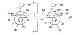
- FIG. 4 is a cross-sectional view of a transverse line taken along the line IV-IV in FIGS.
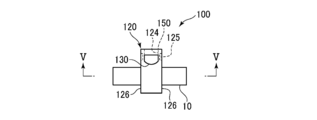
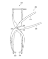
- FIG. 4 is a cross-sectional view of the hook taken along the line VV in FIGS. 2 and 3. It is the perspective view which showed the sizer schematically.
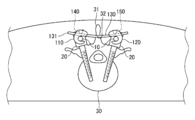
- the transverse 100 mainly includes two hooks 110 and 120, a transverse bar 130, and set screws 140 and 150.
- the hooks 110 and 120 have a U-shaped cross-sectional shape and mainly include bar holes 111 and 121, rod openings 113 and 123, screw holes 114 and 124, and hook holder recesses 115 and 125.
- the U-shaped inner peripheral surfaces of the hooks 110 and 120 form rod openings 113 and 123, respectively.
- the size of the openings of the rod openings 113 and 123 is such that the rod 10 described later can easily enter the rod openings 113 and 123.
- the diameter of the rod openings 113 and 123 is such that the rod 10
- the length is such that it can be easily accommodated.
- the rod opening 123 has a protrusion 127 (see FIG. 5) running in the circumferential direction, and the rod opening 113 also has a similar protrusion not shown.
- the bar holes 111 and 121 are holes having a rectangular cross section that penetrates the hooks 110 and 120 while part of the bar holes 111 and 121 are in contact with part of the rod openings 113 and 123, that is, the rod holes 113 and 123 open.
- the size of the rectangular cross section of the bar holes 111 and 121 is slightly larger than the cross section of the transverse bar 130.
- the screw holes 114 and 124 are holes having an axis that intersects the bar holes 111 and 121, and have inner peripheral surfaces in which female threads are cut. In the front view shown in FIG. 2, the bar holes 111 and 121 penetrate the hooks 110 and 120 in the left-right direction, and the screw holes penetrate from the top surfaces of the hooks 110 and 120 toward the bar holes 111 and 121.
- Hook holder recesses 115 and 125 are depressions having an oval cross section, and are provided one on each of the two side surfaces 116 and 126 of the hooks 110 and 120.
- the transverse bar 130 has a kamaboko-shaped cross section, and is curved with a predetermined curvature with respect to the longitudinal direction.
- One end 131 of the transverse bar 130 has a bullet shape.
- the predetermined curvature is, for example, 120 mm.
- the transverse bar 130 is prepared, for example, with six lengths, and the lengths are, for example, 30 mm, 40 mm, 50 mm, 60 mm, 70 mm, and 80 mm.
- the set screws 140 and 150 are so-called enamel sets, and their tips have a pointed shape, and their heads can be engaged with the tips of a set screw driver 700 (see FIG. 11) described later. Hexagonal or star-shaped grooves are provided.
- One rod 10 is accommodated in each of the two rod openings 113 and 114, and the transverse bar 130 is inserted in the two bar holes 111 and 121.
- the set screws 140 and 150 are screwed into the screw holes 114 and 124.
- the set screws 140 and 150 press the transverse bar 130, and thereby the transverse bar 130 is restrained in the longitudinal direction. Since part of the bar holes 111 and 121 are in contact with the rod openings 113 and 123, the pressed transverse bar 130 contacts the rod 10 and presses the rod 10 against the rod openings 113 and 123.
- the protrusion 127 engages with the rod 10, and the hooks 110 and 120 are restrained in the longitudinal direction and the circumferential direction of the rod 10.
- the interval between the two rods 10 is fixed and kept constant. Further, since the transverse bar 130 is restrained by the two hooks 110 and 120, the hooks 110 and 120 do not rotate in the circumferential direction of the rod 10. The transverse bars 130 are restrained in the longitudinal direction of the rod 10 by restraining the hooks 110 and 120 in the longitudinal direction of the rod 10.
- the transverse 100 in the state where the transverse 100 is assembled to the rod 10, the length from the upper end of the rod 10 to the upper end of the transverse 100 is not integrated with the transverse bar and the hook in the conventional transverse. It is kept lower than the thing. That is, the transverse 100 according to the present embodiment has a low profile shape in which the length from the upper end of the rod 10 to the upper end of the transverse 100 is shorter than the conventional one. Generally, the transverse is placed under the skin and soft tissue. The transverse provided in this way may push up the skin and soft tissue toward the outside of the body and cause damage to them. Since the transverse 100 according to the present embodiment has a low profile shape, it is difficult to push the skin and soft tissue toward the outside of the body, thereby preventing the skin and soft tissue from being damaged.
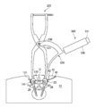
- the surgical instrument mainly includes a sizer 200, a vertebral owl 300, a hook holder 500, and a bar holder 600, and optionally includes a soft tissue owl 400 or a set screw driver 700.
- a sizer 200 mainly includes a sizer 200, a vertebral owl 300, a hook holder 500, and a bar holder 600, and optionally includes a soft tissue owl 400 or a set screw driver 700.
- the sizer 200 will be described with reference to FIG.
- the sizer 200 mainly includes two sizer bars 210 and 220, a centering shaft 230, a lock mechanism 240, and a scale unit 250.
- the sizer bars 210 and 220 are S-shaped thin plates having a thickness of, for example, 2.5 mm, and have holes at or near the S-shaped inflection point.
- the diameter of the hole provided in the sizer bar 210 is substantially the same as the diameter of the centering shaft 230, and the centering shaft 230 has a cylindrical shape with a male screw cut, for example, a diameter of 5 mm, and is provided in the sizer bar 210. It fits into the hole and is fixed to the sizer bar 210.
- the diameter of the hole 221 provided in the sizer bar 220 is slightly larger than the diameter of the centering shaft 230.
- the centering shaft 230 is restrained in the axial direction with respect to the hole 221 and is rotatably supported.
- the axial length of the centering shaft 230 is longer than the thickness of the sizers 210 and 220, and has a predetermined length, for example, 15 mm.
- the lock mechanism 240 and the scale unit 250 are attached to one end of the sizer bars 210 and 220.
- the scale part 250 is a plate-shaped rectangular parallelepiped, and a scale is shaken on the side surface.
- One end of the scale portion 250 is fixed to one end of the sizer bar 220 so as to be rotatable around an axis parallel to the axis of the centering shaft 230.
- the other end of the scale portion 250 passes through a hole 241 formed at one end of the sizer bar 210.
- the lock mechanism 240 includes a hole 241.
- a material having a high coefficient of friction is provided on the inner peripheral portion of the hole 241. This material has a friction coefficient such that the scale portion 250 inserted into the hole 241 does not easily move through the hole 241.
- the sizer bars 210 and 220 do not easily rotate with respect to the centering shaft 230, and the positional relationship between the sizer bar 210 and the sizer bar 220 can be easily maintained.
- the other ends of the sizer bars 210 and 220 are provided with gripping end portions 212 and 222 for rods, respectively.
- the gripping end portions 212 and 222 for the rod have a shape obtained by removing a little half of the cylinder in a plane parallel to the central axis.
- the diameters of the inner peripheral surfaces of the rod gripping end portions 212 and 222 are slightly longer than the outer diameter of the rod 10. Due to the action of the lock mechanism 240, the distance between the rod gripping end portions 212 and 222 does not easily change.
- the scale value of the scale portion 250 indicated by the end of the hole 241 indicates the distance between the two rods 10.
- the rod grip end portions 212 and 222 are provided with screw holes 223 penetrating from the outer peripheral surface to the inner peripheral surface of the rod grip end portions 212 and 222, respectively. If the two rods 10 are not parallel or the like, there is a possibility that the rod holding ends 212 and 222 may not be able to hold the rod 10 reliably, which may make it easier for the rod holding ends 212 and 222 to come off the rod 10. There is sex. When it is necessary to prevent this and securely hold the rod 10, a fixing screw 260 having a screw gripping portion 261 and a screw tip portion 262 is used.
- the screw grip portion 261 has a cylindrical shape, and the screw tip portion 262 has a shape in which a male screw is cut on the outer periphery and the tip is pointed.
- the screw tip portion 262 is screwed into the screw hole 223, protrudes from the inner peripheral surface of the rod gripping end portions 212 and 222, and sinks into the outer peripheral surface of the rod 10. .
- the grip end portions 212 and 222 for the rod reliably hold the rod 10.
- the vertebra owl 300 mainly includes a first vertebra owl bar 310, a second vertebra owl bar 320, and a hollow shaft 330.
- the first vertebra Owl bar 310 is an S-shaped thin plate having a thickness of 5 mm, for example, and has a hole not shown in the vicinity of the S-shaped inflection point.
- the second vertebra Owl bar 320 is a sickle-shaped thin plate and has a hole 321 near the center.
- the diameter of the hole provided in the first vertebra Owl bar 310 and the hole 321 provided in the second vertebra Owl bar 320 are slightly larger than the outer diameter of the hollow shaft 330.
- the axial length of the centering shaft 230 is longer than the sum of the thicknesses of the sizers 210 and 220, the first vertebra Owl bar 310, and the second vertebra Owl bar 320.
- first vertebra owl bar 310 is provided with a sharp vertebra tip 311 having a sharp tip
- second vertebra owl bar 320 is provided with a vertebra recess 322 having a recess at the tip.
- One end of the first vertebra Owl bar 310 and the second vertebra Owl bar 320 is when the first vertebra Owl bar 310 and the second vertebra Owl bar 320 pivot with respect to the axis of the hollow shaft 330 and contact each other. It is bent at right angles to the axis of the hollow shaft 330 so as to be in a straight line.
- the centering shaft 230 is inserted into the inner periphery of the hollow shaft 330, and a nut (not shown) is screwed with the male screw of the centering shaft 230 to fix the vertebra Owl 300 in the axial direction.
- the first vertebra Owl bar 310 and the second vertebra Owl bar 320 can pivot about the axis of the centering shaft 230.
- the distance from the axis of the centering shaft 230 to the tip of the sharpened vertebra 311 is determined in accordance with the position of the hole formed in the spinous process of the vertebra.
- the soft tissue Owl 400 mainly includes an Owl extension portion 410, a penetration portion 420, and an Owl handle 430.
- the owl extension portion 410 is an arc-shaped thin plate having a thickness of 5 mm, for example, and has a hole 411 at one end thereof.
- the hole 411 can be loosely fitted to the centering shaft 230.
- the other end of the Owl extension portion 410 is connected to the penetration portion 420.
- the penetration part 420 has a needle shape that draws an arc with a predetermined curvature.
- the center of the arc in the penetration part 420 coincides with the center of the hole 411.
- the curvature of the penetration part 420 is the same as the curvature of the transverse bar 130.
- the distal end of the penetration part 420 is pointed and forms a sharp part 421 for soft tissue.
- An Owl handle 430 is attached to the rear end of the penetration part 420.
- the axial length of the centering shaft 230 is longer than the total length of the thicknesses of the sizer bars 210 and 220 and the soft tissue Owl 400.
- the centering shaft 230 is inserted into the hole 411, and a nut (not shown) is screwed with the male screw of the centering shaft 230 to fix the soft tissue Owl 400 in the axial direction.
- the soft tissue Owl 400 can turn around the axis of the centering shaft 230, that is, the penetration portion 420 can turn around the axis of the centering shaft 230.
- the distance from the axis of the centering shaft 230 to the soft tissue sharpened portion 421 is determined according to the position where the transverse bar 130 is provided.
- the hook holder 500 mainly includes a hook holder extending portion 510, a hook holder arm 520, and a hook holder handle 530.
- the hook holder extending portion 510 is, for example, an arc-shaped thin plate having a thickness of 5 mm, and has a hole 511 at one end thereof.
- the hole 511 can be loosely fitted to the centering shaft 230.
- the other end of the hook holder extending portion 510 is connected to the hook holder arm 520.
- the hook holder arm 520 is an arc-shaped thin plate and includes a hook grip 522 at the tip thereof.
- a hook holder handle 530 is attached to the rear end of the hook holder arm 520.
- the hook holder handle 530 is provided with a hook operation unit 531.
- the hook holding part 522 mainly has a movable part 523, a fixed part 524, and a protrusion 525 and a protrusion 526 having an oval cross section.
- the protrusion 525 protrudes from the movable portion 523, and the protrusion 526 protrudes from the fixed portion so as to face the protrusion 525.
- the sizes of the protrusions 525 and the protrusions 526 are slightly smaller than the hook holder recesses 115 and 125.
- the movable portion 523 is movable along the protrusion direction of the protrusion 525 and the protrusion 526 so as to change the interval between the protrusion 525 and the protrusion 526.
- the movable portion 523 is connected to the hook operation portion 531 via a wire (not shown) that passes through the inside of the hook holder arm 520.
- the hook operation unit 531 is provided so as to be rotatable with respect to the hook holder handle 530.
- the movable portion 523 is closed, that is, when the distance between the protrusion 525 and the protrusion 526 is the shortest, when the hook operation portion 531 is rotated clockwise, the wire or the like is wound and the movable portion 523 pulled by the wire or the like. Moves so as to widen the gap between the protrusion 525 and the protrusion 526.
- the movable portion 523 when the movable portion 523 is open, that is, when the distance between the protrusion 525 and the protrusion 526 is wide, if the hook operation portion 531 is rotated counterclockwise, the wire or the like is released, and the force from the wire or the like is released.
- the lost movable part 523 moves so as to narrow the interval between the protrusion 525 and the protrusion 526. Thereby, the hook holder 500 can grip or release the hooks 110 and 120.
- the axial length of the centering shaft 230 is longer than the total length of the sizers 210 and 220 and the hook holder 500.
- the centering shaft 230 is inserted into the hole 511, and the hook holder 500 is fixed in the axial direction by screwing a nut (not shown) with the male screw of the centering shaft 230.
- the hook holder 500 can turn around the axis of the centering shaft 230, that is, the hook grip 522 can turn around the axis of the centering shaft 230.
- the distance from the hook hole holes 111 and 121 attached to the hook holding portion 522 to the axis of the centering shaft 230 is the distance from the axis of the centering shaft 230 to the rod holding ends 212 and 222, that is, the axis of the centering shaft 230. And is determined according to the positional relationship between the rod 10 and the rod 10.
- the bar holder 600 mainly includes a bar holder extending portion 610, a bar holder arm 620, and a bar holder handle 630.
- the bar holder extending portion 610 is, for example, an arc-shaped thin plate having a thickness of 5 mm, and has a hole 611 at one end thereof.
- the hole 611 can be loosely fitted to the centering shaft 230.
- the other end of the bar holder extension 610 is connected to the bar holder arm 620.
- the bar holder arm 620 is a thin plate that draws an arc with a predetermined curvature, and includes a bar grip 622 at the tip thereof.
- the center of the arc in the bar holder arm 620 coincides with the center of the hole 611.
- the curvature of the bar holder arm 620 is the same as that of the transverse bar 130 and the penetration part 420.
- a bar holder handle 630 is attached to the rear end of the bar holder arm 620.
- the bar holder handle 630 is provided with a bar operation unit 631.
- the bar gripping part 622 mainly has a movable part 623 and a fixed part 624.
- the movable part 623 is movable so as to change the distance from the fixed part 624.
- the movable portion 623 is connected to the bar operation portion 631 via a wire (not shown) that passes through the inside of the bar holder arm 620.
- the bar operation unit 631 is provided to be rotatable with respect to the bar holder handle 630.
- the movable portion 623 is closed, that is, when the distance between the movable portion 623 and the fixed portion 624 is the shortest, when the bar operation portion 631 is rotated clockwise, the wire is wound and the movable portion is pulled by the wire or the like.
- the part 623 moves so as to widen the distance from the fixed part 624.
- the bar operation unit 631 when the bar operation unit 631 is rotated counterclockwise when the movable unit 623 is open, that is, when the interval between the movable unit 623 and the fixed unit 624 is widened, the wire is released and the The movable part 623 that has lost the force moves so as to narrow the distance from the fixed part 624.
- the bar holder 600 can grip or release the transverse bar 130.
- the axial length of the centering shaft 230 is longer than the sum of the thicknesses of the sizer bars 210 and 220 and the bar holder 600, and preferably the sizer bars 210 and 220, the hook holder 500, the bar holder 600, and a later-described length. It is about the total length of the nut thickness.
- the centering shaft 230 is inserted into the hole 611, and the nut (not shown) is screwed with the male screw of the centering shaft 230 to fix the bar holder 600 in the axial direction.
- the bar holder 600 can turn around the axis of the centering shaft 230, that is, the bar gripper 622 can turn around the axis of the centering shaft 230.
- the distance from the bar gripping portion 622 to the axis of the centering shaft 230 is the distance from the axis of the centering shaft 230 to the vertebral sharpened portion 311 and the vertebral recess 322, that is, the centering shaft when the sizer 200 is fixed to the rod 10. It is determined to be equal to the distance between the axis 230 and a hole 32 (see FIG. 15) formed in the spinous process 31 described later.
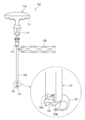
- the set screw driver 700 mainly includes a grip rotation unit 710, a grip fixing unit 720, and a holding tube 730.
- the gripping rotation unit 710 includes a T-shaped handle 711, a torque management mechanism 712, and a driver shaft 713.
- the T-shaped handle 711 is T-shaped and has a shape that can be easily grasped by a human hand.
- the torque management mechanism 712 extends from the T-shaped handle 711 along the rotation axis of the T-shaped handle 711.
- the torque management mechanism 712 controls the rotational torque transmitted from the T-shaped handle 711 to the driver shaft so as not to exceed a desired value.
- the driver shaft 713 is a cylindrical shaft extending from the torque management mechanism 712 along the rotation axis of the T-shaped handle 711 and includes a driver portion 714 at the tip.
- Driver portion 714 has a hexagonal column shape, a star column shape, or a cylindrical shape whose inner surface is a hexagonal column or a star column, and engages with a groove or a protrusion provided on the heads of set screws 140 and 150.
- the grip fixing portion 720 has a substantially cylindrical shape, and the outer peripheral surface has a plurality of portions that slightly protrude in the radial direction. With these multiple parts, a human hand can easily and securely grasp the grip fixing part 720.
- the holding tube 730 has a cylindrical shape having an inner diameter slightly longer than the outer diameter of the driver shaft 713.
- the distal end 731 of the holding tube 730 has a shape obtained by deleting the outer peripheral surface of the cylinder with two parallel surfaces, and has two holding portions 732a and 732b protruding in parallel.
- the driver portion 714 protrudes from between the holding portions 732a and 732b.
- the practitioner attaches the set screw 140 to the driver portion 714, sandwiches the hook 110 between the holding portions 732a and 732b, and then screws the set screw 140 into the screw hole 114. Then, the T-shaped handle 711 is rotated with the other hand while supporting the grip fixing portion 720 with one hand. Thereby, the driver shaft 713 and the driver part 714 rotate. Since the hook 110 is sandwiched between the holding portions 732a and 732b and the holding and fixing portion 720 is held by hand, when the T-shaped handle 711 is rotated, the hook 110 does not rotate together, and the set screw 140 is screwed into the screw hole 114. When the predetermined torque is reached, the torque management mechanism 712 makes a sound. The practitioner who has heard this stops rotating the T-shaped handle 711 and completes the installation of the set screw 140. The same operation is performed on the hook 120 and the set screw 150, and the set screw 150 is attached to the hook 120.
- the means for attaching the sizer 200 to the rod 10 will be described with reference to FIG.
- the practitioner grasps one end of the two sizer bars 210 and 220, and inserts the grasping ends 212 and 222 for the rods into the holes 42 slightly opened in the skin 40 and the soft tissue 41. Then, when one end of the sizer bars 210 and 220 is gripped so that the rod 10 is engaged with the inner peripheral surfaces of the rod gripping end portions 212 and 222, the rod 10 is placed on the inner peripheral surfaces of the rod gripping end portions 212 and 222. , And the lock mechanism 240 makes it difficult for the rod gripping end portions 212 and 222 to be detached from the rod 10. Thereby, the sizer 200 is attached to the rod 10.
- the practitioner can know the interval between the two rods 10 by referring to the scale of the scale portion 250. The practitioner determines the length of the transverse bar 130 in consideration of the distance between the rods 10. By utilizing the hole 42, the sizer 200 can be attached to the rod 10 percutaneously without incision.
- the practitioner grasps the end portions of the first vertebra Owl bar 310 and the second vertebra Owl bar 320 and inserts the sharp vertebra 311 and the vertebra recess 322 into the hole 42. Thereafter, the practitioner inserts the centering shaft 230 on the inner periphery of the hollow shaft 330. Then, a nut is attached to the centering shaft 230 to prevent the vertebra owl 300 from moving in the axial direction of the centering shaft 230.
- the distance between the vertebral sharpened portion 311 and the vertebral concave portion 322 approaches, and the vertebral sharpened portion 311 approaches.
- the vertebral recess 322 collide with the spinous process 31.
- the sharp vertebra 311 and the vertebra recess 322 penetrate the spinous process 31 and open the hole 32. (See FIG. 14).
- the practitioner can By simply grasping the ends of 310 and the second vertebral owl bar 320, the hole 32 can be easily formed at an appropriate position.
- the practitioner When the practitioner confirms that the vertebral sharpened tip 311 and the vertebral concave portion 322 are in contact with each other through the sense of the hand, the practitioner moves the end portions of the first vertebra owl bar 310 and the second vertebra owl bar 320. By operating, the space
- the practitioner inserts the centering shaft 230 into the inner periphery of the hole 411. Then, a nut is attached to the centering shaft 230 to prevent the soft tissue Owl 400 from moving in the axial direction of the centering shaft 230. Thereafter, the practitioner grasps the Owl handle 430 and inserts the sharp portion 421 for soft tissue into the skin 40 and the soft tissue 41. After inserting the soft tissue sharpened portion 421 until the hole 42 is reached, the Owl handle 430 is operated to pull out the soft tissue sharpened portion 421 from the skin 40 and the soft tissue 41.
- the curvature of the penetration portion 420 is the same as the curvature of the transverse bar 130, and the distance from the axis of the centering shaft 230 to the soft tissue sharpened portion 421 depends on the position where the transverse bar 130 is provided. It has been decided. Therefore, the curvature of the hole 43 is the same as the curvature of the transverse bar 130, and the position of the hole 43 is continuous with the position where the transverse bar 130 is provided when the transverse bar 130 is inserted into the hole 43. It will be connected position.
- the nut After pulling out the sharp portion 421 for soft tissue, the nut is removed from the centering shaft 230, and the Owl 400 for soft tissue is removed from the centering shaft 230. Thereby, the means for making the hole 43 in the soft tissue 40 using the soft tissue Owl 400 is completed.
- the soft tissue Owl 400 By using the soft tissue Owl 400, it is possible to perforate the soft tissue 40 percutaneously without incision.
- the practitioner rotates the hook operation unit 531 to open the movable unit 523.
- the hook 110 is placed between the movable portion 523 and the fixed portion 524 so that the protrusion 525 and the protrusion 526 are fitted in the two hook holder recesses 115, respectively, and the hook operation portion 531 is rotated to move the movable portion 523. Close. As a result, the hook 110 is fixed to the hook grip 522.
- the practitioner grips the hook holder handle 530 and inserts the hook grip 522 and the hook 110 into the hole 42. Thereafter, the practitioner inserts the centering shaft 230 into the inner periphery of the hole 511. A nut is attached to the centering shaft 230 to prevent the hook holder 500 from moving in the axial direction of the centering shaft 230.
- the practitioner operates the hook holder handle 530 to turn the hook holder 500 around the axis of the centering shaft 230 and attach the hook 110 to the rod 10.
- the distance from the bar hole 111 of the hook 110 attached to the hook grip 522 to the axis of the centering shaft 230 is determined according to the positional relationship between the axis of the centering shaft 230 and the rod 10.
- the rod 10 enters the bar hole 111 and the hook 110 is attached to the rod 10 simply by turning the hook holder 500 around the axis of the centering shaft 230. Thereby, the means for attaching the hook 110 to the rod 10 using the hook holder 500 is completed.
- the hook 110 can be attached to the rod 10 through the hole 42 percutaneously without incision.
- the practitioner determines the length of the transverse bar 130 with reference to the scale portion 250 of the sizer 200 as described above.
- the transverse bar 130 having the determined length is attached to the bar holder 600.
- the bar operating unit 631 is rotated to open a space between the movable unit 623 and the fixed unit 624.
- the transverse bar 130 is placed between the movable part 623 and the fixed part 624, the bar operation part 631 is rotated, and the movable part 623 is closed.
- the transverse bar 130 is fixed to the bar gripping portion 622.
- the practitioner inserts the centering shaft 230 into the inner periphery of the hole 611. Then, a nut is attached to the centering shaft 230 to prevent the bar holder 600 from moving in the axial direction of the centering shaft 230. Thereafter, the practitioner inserts the transverse bar 130 into the hole 43 while holding the bar holder handle 630 and turning the bar holder 600 around the axis of the centering shaft 230. Then, the bar holder 600 is further swung around the centering shaft 230, and the transverse bar 130 enters the hole 32 and the bar hole 111.
- the curvature of the bar gripping portion 622 is the same as the curvature of the transverse bar 130, and the distance from the bar gripping portion 622 to the axis of the centering shaft 230 is the same as that when the sizer 200 is fixed to the rod 10. It is determined to be equal to the distance between the axis of the centering shaft 230 and the hole 32. Therefore, the transversal bar 130 can be formed into the hole 43, the hole 32, and the bar hole without receiving resistance from the soft tissue 41, the spinous process 31, and the hook 110 only by turning the bar holder 600 around the axis of the centering shaft 230. 111 can be easily entered (see FIG. 17).
- the means for penetrating the transverse bar 130 through the soft tissue 41, the hole 32, and the hook 110 using the bar holder 600 is completed.
- the transverse bar 130 can penetrate the soft tissue 41, the hole 32, and the hook 110 percutaneously without incision.
- the practitioner After confirming that the transverse bar 130 has completely penetrated the bar hole 111, the practitioner attaches the set screw 140 to the set screw driver 700, inserts the tip 731 into the hole 42, and holds the holding portions 732 a and 732 b. After the hook 110 is sandwiched therebetween, the set screw 140 is screwed into the screw hole 114. Then, the T-shaped handle 711 is rotated with the other hand while supporting the grip fixing portion 720 with one hand. Since the hook 110 is sandwiched between the holding portions 732a and 732b and the holding and fixing portion 720 is held by hand, when the T-shaped handle 711 is rotated, the hook 110 does not rotate together, and the set screw 140 is screwed into the screw hole 114.
- the set screw 140 is not screwed into the screw hole 114 until a predetermined torque is reached, but is screwed into the screw hole 114 to such an extent that the set screw 140 slightly contacts the transverse bar 130.
- the means for temporarily fixing the transverse bar 130 to the hook 110 and the rod 10 using the set screw 140 is completed.
- the set screw 140 can be percutaneously screwed into the screw hole 114 without incision.
- the practitioner operates the hook operation unit 531 to fix the hook 120 to the hook holding unit 522.
- the practitioner grips the hook holder handle 530 and inserts the hook grip 522 and the hook 120 into the hole 42.
- the practitioner attaches the hook holder 500 to the centering shaft 230 as described above.
- the practitioner operates the hook holder handle 530 to pivot the hook holder 500 around the axis of the centering shaft 230 and attach the hook 120 to the transverse bar 130 and the rod 10.
- the distance from the bar hole 121 of the hook 120 attached to the hook grip 522 to the axis of the centering shaft 230 is determined according to the positional relationship between the axis of the centering shaft 230 and the rod 10. Therefore, the rod 10 enters the bar hole 121 and the hook 120 is attached to the rod 10 simply by turning the hook holder 500 around the axis of the centering shaft 230.
- the practitioner uses the same means as described above until the set screw 140 comes into light contact with the transverse bar 130.
- the set screw 150 is screwed into the screw hole 124 with the driver 700.
- the means for attaching the hook 120 to the rod 10 using the hook holder 500 is completed.
- the hook 120 can be attached to the rod 10 and the transverse bar 130 through the hole 42 percutaneously without incision.
- the practitioner holds the hook 110 between the holding portions 732a and 732b, and then fits the set screw 140 into the driver portion 714 of the set screw driver 700, while supporting the grip fixing portion 720 with one hand, To rotate the T-shaped handle 711. Since the hook 110 is sandwiched between the holding portions 732a and 732b and the holding and fixing portion 720 is held by hand, when the T-shaped handle 711 is rotated, the hook 110 does not rotate together, and the set screw 140 is screwed into the screw hole 114. When the predetermined torque is reached, the torque management mechanism 712 makes a sound. The practitioner who has heard this stops rotating the T-shaped handle 711. At this time, the set screw 140 presses the transverse bar 130, whereby the transverse bar 130 is restrained in the longitudinal direction.
- the transverse 100 can be reliably fixed to the rod 10 without damaging the vertebra and without loosening the set screw 140.
- the transverse 100 can be installed percutaneously in minimally invasive surgery.
- the transverse 100 Since the transverse bar 130 penetrates the inside of the hole 32 provided in the spinous process 31, the transverse 100 is fixed in the protruding direction of the vertebra 30. Since osteoporosis patients have fragile bones, when a pedicle screw is attached to a vertebra, the pedicle screw may come out of the vertebra without the screw being effective. However, in this embodiment, since the transverse 100 is fixed in the protruding direction of the vertebra 30, even if a force in the protruding direction of the vertebra 30, that is, a force that escapes from the vertebra 30 acts on the pedicle screw 20. Does not escape from the vertebra 30.
- centering shaft 230 is inserted into the inner periphery of the hollow shaft 330 before inserting the sharpened vertebra 311 and the concave 322 for the vertebra into the hole 42 in the means for making a hole in the spinous process 31 using the owl for the vertebra 300. May be.
- the skin 40 and the soft tissue 41 are used for the soft tissue.
- the sharp part 421 may be inserted somewhat.
- the centering shaft 230 is inserted and fixed to the inner periphery of the hole 511 before the hook holding part 522 and the hook 110 are inserted into the hole 42. Also good.
- the transverse bar 130 is inserted before the centering shaft 230 is inserted and fixed to the inner periphery of the hole 611. 130 may be slightly inserted into the hole 43.
- the hook holder 500 may be attached to the centering shaft 230 before inserting the hook grip 522 and the hook 120 into the hole 42. Good.
- the predetermined curvature is not limited to the aforementioned value.
- the length of the transverse bar is not limited to the above-described value, and the type of length is not limited to six types.
- the scale value of the scale portion 250 indicated by the end of the hole 241 is not the distance between the two rods 10, but the distance between the axes of the two rods 10, the distance outside the two rods 10, or the use.
- the length of the transverse bar 130 to be used may be used.
- the lock mechanism 240 is not limited to the hole 241, and is a lock mechanism 240 that mechanically fixes the sizer bar 210 to the sizer bar 220 such as a frictional resistance provided between the hole 221 and the centering shaft 230. There may be.
- the soft tissue Owl 400 may not always be used.
- a hole may be formed in the soft tissue 40 only when the soft tissue 43 is thick and the transverse bar 130 cannot be easily inserted from the hole 42.
- the numbers representing the size of the transverse 100 shown in the figure are merely examples, and the size of the transverse 100 according to the present invention is not limited to these values.
Landscapes
- Health & Medical Sciences (AREA)
- Orthopedic Medicine & Surgery (AREA)
- Neurology (AREA)
- Life Sciences & Earth Sciences (AREA)
- Surgery (AREA)
- Heart & Thoracic Surgery (AREA)
- Engineering & Computer Science (AREA)
- Biomedical Technology (AREA)
- Nuclear Medicine, Radiotherapy & Molecular Imaging (AREA)
- Medical Informatics (AREA)
- Molecular Biology (AREA)
- Animal Behavior & Ethology (AREA)
- General Health & Medical Sciences (AREA)
- Public Health (AREA)
- Veterinary Medicine (AREA)
- Dentistry (AREA)
- Oral & Maxillofacial Surgery (AREA)
- Surgical Instruments (AREA)
Abstract
Description
20 ペディクルスクリュー
30 椎骨
31 棘突起
100 トランスバース
110 フック
120 フック
130 トランスバースバー
140 セットスクリュー
150 セットスクリュー
200 サイザー
300 椎骨用オウル
400 軟部組織用オウル
500 フックホルダー
600 バーホルダー
700 セットスクリュードライバ
Claims (15)
- 椎骨に挿入されるスクリューを繋ぐロッドと係合するフックと、
所定の曲率を有し、複数の前記フックとの間に設けられるトランスバースバーと
を備えるトランスバース。 - 前記トランスバースバーは、前記椎骨の棘突起を貫通して設けられる請求項1に記載のトランスバース。
- 前記フックは、前記トランスバースバーが貫通するバーホールを有する請求項1または2に記載のトランスバース。
- 前記フックは、前記ロッドと係合するロッド開口部を有する請求項1に記載のトランスバース。
- 前記フックは、前記トランスバースバーが貫通するバーホールと、前記ロッドと係合するロッド開口部とを備え、前記バーホールは、前記ロッド開口部と貫通する請求項1に記載のトランスバース。
- 前記トランスバースバーは、前記トランスバースバーを把持するバーホルダーと係合可能なバーホルダー用凹部を備える請求項1に記載のトランスバース。
- 前記フックは、前記フックを把持するフックホルダーと係合可能なフックホルダー用凹部を備える請求項1に記載のトランスバース。
- 前記フックは、前記バーホールに貫通するスクリューホールを備え、
前記トランスバースは、前記スクリューホールに螺合するセットスクリューをさらに備え、
前記セットスクリューが前記スクリューホールに進入すると、前記セットスクリューの先端は前記トランスバースバーと係合して押圧し、前記セットスクリューの先端に押圧された前記トランスバースバーは、前記ロッドを押圧して前記ロッド開口部に押しつける請求項1に記載のトランスバース。 - 前記ロッドは、異なる椎骨に挿入される複数のスクリューを接続し、前記フックは、2本のロッドに1つずつ取り付けられる請求項1から8のいずれかに記載のトランスバース。
- 2本のサイザーバーと、
前記2本のサイザーバーを所定の軸上で軸支するセンタリングシャフトと、
前記センタリングシャフトに対する前記サイザーバーの回転を防止するロック機構とを備え、
前記サイザーバーの一端には、椎骨に挿入されるスクリューを繋ぐロッドと係合するロッド用把持端部が設けられるサイザー。 - 2本の椎骨用オウルバーと、
前記2本の椎骨用オウルバーを所定の軸上で軸支するセンタリングシャフトとを備え、
前記センタリングシャフトは、前記所定の軸と同軸の孔を有し、
前記椎骨用オウルバーの一端には、前記椎骨に孔を空ける椎骨用先鋭部が設けられる
椎骨用オウル。 - 一端が所定の軸によって軸支され、前記所定の軸から径方向に延びるオウル延伸部と、
所定の曲率を有し、前記オウル延伸部の他端から延びる貫入部とを備え、
前記貫入部の先端には、軟部組織に孔を空ける軟部組織用先鋭部が設けられる
軟部組織用オウル。 - 一端が所定の軸によって軸支され、前記所定の軸から径方向に延びるフックホルダー延伸部と、
前記フックホルダー延伸部の他端から延びるフックホルダーアームとを備え、
前記フックホルダーアームの先端には、フックを把持するフック把持部が設けられる
フックホルダー。 - 一端が所定の軸によって軸支され、前記所定の軸から径方向に延びるバーホルダー延伸部と、
所定の曲率を有し、前記バーホルダー延伸部の他端から延びるバーホルダーアームとを備え、
前記バーホルダーアームの先端には、バーを把持するバー把持部が設けられる
バーホルダー。 - 請求項1に記載のトランスバースを取り付けるために用いられる手術器具であって、請求項10に記載のサイザーと、請求項11に記載の椎骨用オウルと、請求項13に記載のフックホルダーと、請求項14に記載のバーホルダーとを備える手術器具。
Priority Applications (4)
| Application Number | Priority Date | Filing Date | Title |
|---|---|---|---|
| JP2017567938A JP6867628B2 (ja) | 2016-02-15 | 2016-06-23 | トランスバース、および手術器具 |
| US16/077,956 US10905473B2 (en) | 2016-02-15 | 2016-06-23 | Transverse, and surgical instrument |
| EP16890597.4A EP3417818B1 (en) | 2016-02-15 | 2016-06-23 | Transverse, and surgical instrument |
| US17/125,813 US11678916B2 (en) | 2016-02-15 | 2020-12-17 | Transverse, and surgical instrument |
Applications Claiming Priority (2)
| Application Number | Priority Date | Filing Date | Title |
|---|---|---|---|
| JP2016-025789 | 2016-02-15 | ||
| JP2016025789 | 2016-02-15 |
Related Child Applications (2)
| Application Number | Title | Priority Date | Filing Date |
|---|---|---|---|
| US16/077,956 A-371-Of-International US10905473B2 (en) | 2016-02-15 | 2016-06-23 | Transverse, and surgical instrument |
| US17/125,813 Continuation US11678916B2 (en) | 2016-02-15 | 2020-12-17 | Transverse, and surgical instrument |
Publications (1)
| Publication Number | Publication Date |
|---|---|
| WO2017141459A1 true WO2017141459A1 (ja) | 2017-08-24 |
Family
ID=59625799
Family Applications (1)
| Application Number | Title | Priority Date | Filing Date |
|---|---|---|---|
| PCT/JP2016/068643 Ceased WO2017141459A1 (ja) | 2016-02-15 | 2016-06-23 | トランスバース、および手術器具 |
Country Status (4)
| Country | Link |
|---|---|
| US (2) | US10905473B2 (ja) |
| EP (1) | EP3417818B1 (ja) |
| JP (1) | JP6867628B2 (ja) |
| WO (1) | WO2017141459A1 (ja) |
Cited By (1)
| Publication number | Priority date | Publication date | Assignee | Title |
|---|---|---|---|---|
| WO2020035958A1 (en) * | 2018-08-16 | 2020-02-20 | Medtronic Sofamor Danek, Co., Ltd. | Spinal implant system and method |
Families Citing this family (4)
| Publication number | Priority date | Publication date | Assignee | Title |
|---|---|---|---|---|
| JP6867628B2 (ja) * | 2016-02-15 | 2021-04-28 | 株式会社アスロメディカル | トランスバース、および手術器具 |
| CN118102992A (zh) * | 2021-10-18 | 2024-05-28 | 查尔斯·卡纳利 | 脊柱固定工具、系统和方法 |
| US20240299065A1 (en) * | 2023-03-08 | 2024-09-12 | Nuvasive, Inc. | Percutaneous posterior fixation |
| WO2026041563A1 (en) * | 2024-08-22 | 2026-02-26 | Moving Spine Ag | Device for guiding a filament around one or more vertebrae |
Citations (13)
| Publication number | Priority date | Publication date | Assignee | Title |
|---|---|---|---|---|
| JPH06165789A (ja) * | 1992-11-06 | 1994-06-14 | Biomat | 脊柱癒合用骨接合装置 |
| JPH08505785A (ja) * | 1992-11-13 | 1996-06-25 | ソファモル・エス・エヌ・セ | 後方接近により脊椎すべり症を矯正するための腰仙骨接合及び器具ネジ |
| JPH09510628A (ja) * | 1992-09-21 | 1997-10-28 | レイ,アール・チャールズ | 側湾脊柱の減捻を達成させる工具及び方法 |
| JPH1080432A (ja) * | 1996-06-03 | 1998-03-31 | Stryker Fr Sa | 脊椎骨接合手術用ロッド間の剛性横断リンク形成装置 |
| JP2003511190A (ja) * | 1999-10-20 | 2003-03-25 | エスディージーアイ・ホールディングス・インコーポレーテッド | 骨構造体の安定化用器具及び方法 |
| JP2006503672A (ja) | 2002-10-28 | 2006-02-02 | エスディージーアイ・ホールディングス・インコーポレーテッド | 脊椎インプラントのための多軸交差結合連結システム |
| JP2007508118A (ja) * | 2003-10-14 | 2007-04-05 | ジンテス ゲゼルシャフト ミット ベシュレンクテル ハフツング | 脊椎固定フックおよび脊椎固定方法 |
| JP2009533173A (ja) | 2006-04-10 | 2009-09-17 | ウォーソー・オーソペディック・インコーポレーテッド | 骨取付器を相互接続するための方法と装置 |
| JP2009537242A (ja) | 2006-05-15 | 2009-10-29 | ウォーソー・オーソペディック・インコーポレーテッド | 脊椎インプラントアセンブリの構成要素を相互連結させるための装置 |
| US20130030469A1 (en) | 2011-07-28 | 2013-01-31 | Chris Karas | Systems, methods, and apparatuses for spinal fixation |
| JP2013535306A (ja) * | 2010-08-18 | 2013-09-12 | スパイナル・エレメンツ・インコーポレーテッド | 椎間関節ドリルならびにその使用方法 |
| WO2014045870A1 (ja) * | 2012-09-24 | 2014-03-27 | テルモ株式会社 | 穿刺具組立体 |
| US20150374414A1 (en) * | 2014-06-26 | 2015-12-31 | Zimmer Spine, Inc. | Transverse connector |
Family Cites Families (10)
| Publication number | Priority date | Publication date | Assignee | Title |
|---|---|---|---|---|
| US5814046A (en) | 1992-11-13 | 1998-09-29 | Sofamor S.N.C. | Pedicular screw and posterior spinal instrumentation |
| US7122036B2 (en) * | 1999-07-01 | 2006-10-17 | Spinevision, S.A. | Connector for an osteosynthesis system intended to provide a connection between two rods of a spinal osteosynthesis system, osteosynthesis system using such a connector, and method of implanting such an osteosynthesis system |
| US20070270822A1 (en) * | 2006-04-28 | 2007-11-22 | Sdgi Holdings, Inc. | Bone fixation grommet |
| US8652137B2 (en) * | 2007-02-22 | 2014-02-18 | Spinal Elements, Inc. | Vertebral facet joint drill and method of use |
| US8864798B2 (en) * | 2008-01-18 | 2014-10-21 | Globus Medical, Inc. | Transverse connector |
| KR100942226B1 (ko) * | 2009-09-30 | 2010-02-16 | 주식회사 지에스메디칼 | 로드 홀더 및 이를 이용하는 척추용 최소 침습 수술 시스템 |
| US8870879B2 (en) | 2011-06-16 | 2014-10-28 | Industrial Technology Research Institute | Minimally invasive spinal stabilization method |
| CN105813586B (zh) * | 2013-10-31 | 2020-08-04 | 爱荷华大学研究基金会 | 经皮横向连接器系统 |
| US10258228B2 (en) * | 2014-08-08 | 2019-04-16 | K2M, Inc. | Retraction devices, systems, and methods for minimally invasive spinal surgery |
| JP6867628B2 (ja) * | 2016-02-15 | 2021-04-28 | 株式会社アスロメディカル | トランスバース、および手術器具 |
-
2016
- 2016-06-23 JP JP2017567938A patent/JP6867628B2/ja active Active
- 2016-06-23 US US16/077,956 patent/US10905473B2/en active Active
- 2016-06-23 WO PCT/JP2016/068643 patent/WO2017141459A1/ja not_active Ceased
- 2016-06-23 EP EP16890597.4A patent/EP3417818B1/en active Active
-
2020
- 2020-12-17 US US17/125,813 patent/US11678916B2/en active Active
Patent Citations (13)
| Publication number | Priority date | Publication date | Assignee | Title |
|---|---|---|---|---|
| JPH09510628A (ja) * | 1992-09-21 | 1997-10-28 | レイ,アール・チャールズ | 側湾脊柱の減捻を達成させる工具及び方法 |
| JPH06165789A (ja) * | 1992-11-06 | 1994-06-14 | Biomat | 脊柱癒合用骨接合装置 |
| JPH08505785A (ja) * | 1992-11-13 | 1996-06-25 | ソファモル・エス・エヌ・セ | 後方接近により脊椎すべり症を矯正するための腰仙骨接合及び器具ネジ |
| JPH1080432A (ja) * | 1996-06-03 | 1998-03-31 | Stryker Fr Sa | 脊椎骨接合手術用ロッド間の剛性横断リンク形成装置 |
| JP2003511190A (ja) * | 1999-10-20 | 2003-03-25 | エスディージーアイ・ホールディングス・インコーポレーテッド | 骨構造体の安定化用器具及び方法 |
| JP2006503672A (ja) | 2002-10-28 | 2006-02-02 | エスディージーアイ・ホールディングス・インコーポレーテッド | 脊椎インプラントのための多軸交差結合連結システム |
| JP2007508118A (ja) * | 2003-10-14 | 2007-04-05 | ジンテス ゲゼルシャフト ミット ベシュレンクテル ハフツング | 脊椎固定フックおよび脊椎固定方法 |
| JP2009533173A (ja) | 2006-04-10 | 2009-09-17 | ウォーソー・オーソペディック・インコーポレーテッド | 骨取付器を相互接続するための方法と装置 |
| JP2009537242A (ja) | 2006-05-15 | 2009-10-29 | ウォーソー・オーソペディック・インコーポレーテッド | 脊椎インプラントアセンブリの構成要素を相互連結させるための装置 |
| JP2013535306A (ja) * | 2010-08-18 | 2013-09-12 | スパイナル・エレメンツ・インコーポレーテッド | 椎間関節ドリルならびにその使用方法 |
| US20130030469A1 (en) | 2011-07-28 | 2013-01-31 | Chris Karas | Systems, methods, and apparatuses for spinal fixation |
| WO2014045870A1 (ja) * | 2012-09-24 | 2014-03-27 | テルモ株式会社 | 穿刺具組立体 |
| US20150374414A1 (en) * | 2014-06-26 | 2015-12-31 | Zimmer Spine, Inc. | Transverse connector |
Non-Patent Citations (1)
| Title |
|---|
| See also references of EP3417818A4 |
Cited By (3)
| Publication number | Priority date | Publication date | Assignee | Title |
|---|---|---|---|---|
| WO2020035958A1 (en) * | 2018-08-16 | 2020-02-20 | Medtronic Sofamor Danek, Co., Ltd. | Spinal implant system and method |
| CN112804953A (zh) * | 2018-08-16 | 2021-05-14 | 华沙整形外科股份有限公司 | 脊柱植入物系统和方法 |
| US11602381B2 (en) | 2018-08-16 | 2023-03-14 | Medtronic Sofamor Danek, Co., Ltd. | Spinal implant system and method |
Also Published As
| Publication number | Publication date |
|---|---|
| EP3417818A1 (en) | 2018-12-26 |
| US20210169533A1 (en) | 2021-06-10 |
| US11678916B2 (en) | 2023-06-20 |
| JPWO2017141459A1 (ja) | 2018-12-20 |
| US10905473B2 (en) | 2021-02-02 |
| EP3417818A4 (en) | 2019-10-23 |
| JP6867628B2 (ja) | 2021-04-28 |
| EP3417818B1 (en) | 2026-04-01 |
| US20190125416A1 (en) | 2019-05-02 |
Similar Documents
| Publication | Publication Date | Title |
|---|---|---|
| US8470003B2 (en) | Laminoplasty plates and methods of expanding the spinal canal | |
| JP4673370B2 (ja) | 最小限の侵襲性手技で接続部材を脊柱に隣接配置するシステム | |
| JP4176009B2 (ja) | 外科手術用ロッド調整器具及び方法 | |
| WO2017141459A1 (ja) | トランスバース、および手術器具 | |
| US20110184469A1 (en) | Set screw alignment tool | |
| US9216044B2 (en) | Stripped pedicle screw driver bit | |
| JP2005169064A (ja) | 脊柱変形矯正装置及びその使用方法 | |
| JP2013540476A (ja) | 棘突起の把持システムおよびその使用 | |
| CN105358080A (zh) | 矫形植入套件 | |
| EP3113696B1 (en) | Separable guide instrument for anatomical implant | |
| BR112016030815B1 (pt) | Par de fórceps | |
| US9622794B2 (en) | Polyaxial pedicle screw locking and derotation instrument | |
| US20200038030A1 (en) | Rotation knob assemblies and surgical instruments including the same | |
| US7294140B2 (en) | Device for holding trocar sleeves | |
| EP3531929B1 (en) | Suture connection system for bone plates | |
| WO2016042877A1 (ja) | 脊椎手術用器具 | |
| US10376298B2 (en) | Medical cutting instrument | |
| CA2800403A1 (fr) | Instruments pour la chirurgie rachidienne mini-invasive et leurs applications | |
| CN110225718A (zh) | 用于外科线材和缆线的切割工具 | |
| US20120095467A1 (en) | Surgical instruments for cutting elongated elements and methods of use | |
| US20090157098A1 (en) | Surgical wire closure devices | |
| US20250025220A1 (en) | Cutting device for bone fixing plate | |
| JP2012130724A (ja) | 髄内釘及び整形外科手術器具セット | |
| JP4157126B2 (ja) | 外科用開創器 | |
| CN112890941B (zh) | 一种医用肱骨近端骨折的快速复位内固定系统 |
Legal Events
| Date | Code | Title | Description |
|---|---|---|---|
| 121 | Ep: the epo has been informed by wipo that ep was designated in this application |
Ref document number: 16890597 Country of ref document: EP Kind code of ref document: A1 |
|
| WWE | Wipo information: entry into national phase |
Ref document number: 2017567938 Country of ref document: JP |
|
| NENP | Non-entry into the national phase |
Ref country code: DE |
|
| WWE | Wipo information: entry into national phase |
Ref document number: 2016890597 Country of ref document: EP |
|
| ENP | Entry into the national phase |
Ref document number: 2016890597 Country of ref document: EP Effective date: 20180917 |
|
| WWG | Wipo information: grant in national office |
Ref document number: 2016890597 Country of ref document: EP |