WO2017141819A1 - 車両用ステアリング制御装置 - Google Patents
車両用ステアリング制御装置 Download PDFInfo
- Publication number
- WO2017141819A1 WO2017141819A1 PCT/JP2017/004784 JP2017004784W WO2017141819A1 WO 2017141819 A1 WO2017141819 A1 WO 2017141819A1 JP 2017004784 W JP2017004784 W JP 2017004784W WO 2017141819 A1 WO2017141819 A1 WO 2017141819A1
- Authority
- WO
- WIPO (PCT)
- Prior art keywords
- steering
- differential mechanism
- angle
- eps
- torque
- Prior art date
- Legal status (The legal status is an assumption and is not a legal conclusion. Google has not performed a legal analysis and makes no representation as to the accuracy of the status listed.)
- Ceased
Links
Images


Classifications
-
- B—PERFORMING OPERATIONS; TRANSPORTING
- B62—LAND VEHICLES FOR TRAVELLING OTHERWISE THAN ON RAILS
- B62D—MOTOR VEHICLES; TRAILERS
- B62D15/00—Steering not otherwise provided for
- B62D15/02—Steering position indicators ; Steering position determination; Steering aids
- B62D15/025—Active steering aids, e.g. helping the driver by actively influencing the steering system after environment evaluation
- B62D15/0265—Automatic obstacle avoidance by steering
-
- B—PERFORMING OPERATIONS; TRANSPORTING
- B62—LAND VEHICLES FOR TRAVELLING OTHERWISE THAN ON RAILS
- B62D—MOTOR VEHICLES; TRAILERS
- B62D15/00—Steering not otherwise provided for
- B62D15/02—Steering position indicators ; Steering position determination; Steering aids
- B62D15/025—Active steering aids, e.g. helping the driver by actively influencing the steering system after environment evaluation
-
- B—PERFORMING OPERATIONS; TRANSPORTING
- B62—LAND VEHICLES FOR TRAVELLING OTHERWISE THAN ON RAILS
- B62D—MOTOR VEHICLES; TRAILERS
- B62D5/00—Power-assisted or power-driven steering
- B62D5/008—Changing the transfer ratio between the steering wheel and the steering gear by variable supply of energy, e.g. by using a superposition gear
-
- B—PERFORMING OPERATIONS; TRANSPORTING
- B62—LAND VEHICLES FOR TRAVELLING OTHERWISE THAN ON RAILS
- B62D—MOTOR VEHICLES; TRAILERS
- B62D5/00—Power-assisted or power-driven steering
- B62D5/04—Power-assisted or power-driven steering electrical, e.g. using an electric servo-motor connected to, or forming part of, the steering gear
- B62D5/0457—Power-assisted or power-driven steering electrical, e.g. using an electric servo-motor connected to, or forming part of, the steering gear characterised by control features of the drive means as such
- B62D5/046—Controlling the motor
- B62D5/0463—Controlling the motor calculating assisting torque from the motor based on driver input
-
- B—PERFORMING OPERATIONS; TRANSPORTING
- B62—LAND VEHICLES FOR TRAVELLING OTHERWISE THAN ON RAILS
- B62D—MOTOR VEHICLES; TRAILERS
- B62D5/00—Power-assisted or power-driven steering
- B62D5/04—Power-assisted or power-driven steering electrical, e.g. using an electric servo-motor connected to, or forming part of, the steering gear
- B62D5/0457—Power-assisted or power-driven steering electrical, e.g. using an electric servo-motor connected to, or forming part of, the steering gear characterised by control features of the drive means as such
- B62D5/046—Controlling the motor
- B62D5/0472—Controlling the motor for damping vibrations
-
- B—PERFORMING OPERATIONS; TRANSPORTING
- B62—LAND VEHICLES FOR TRAVELLING OTHERWISE THAN ON RAILS
- B62D—MOTOR VEHICLES; TRAILERS
- B62D6/00—Arrangements for automatically controlling steering depending on driving conditions sensed and responded to, e.g. control circuits
- B62D6/002—Arrangements for automatically controlling steering depending on driving conditions sensed and responded to, e.g. control circuits computing target steering angles for front or rear wheels
-
- B—PERFORMING OPERATIONS; TRANSPORTING
- B62—LAND VEHICLES FOR TRAVELLING OTHERWISE THAN ON RAILS
- B62D—MOTOR VEHICLES; TRAILERS
- B62D6/00—Arrangements for automatically controlling steering depending on driving conditions sensed and responded to, e.g. control circuits
- B62D6/002—Arrangements for automatically controlling steering depending on driving conditions sensed and responded to, e.g. control circuits computing target steering angles for front or rear wheels
- B62D6/003—Arrangements for automatically controlling steering depending on driving conditions sensed and responded to, e.g. control circuits computing target steering angles for front or rear wheels in order to control vehicle yaw movement, i.e. around a vertical axis
-
- B—PERFORMING OPERATIONS; TRANSPORTING
- B62—LAND VEHICLES FOR TRAVELLING OTHERWISE THAN ON RAILS
- B62D—MOTOR VEHICLES; TRAILERS
- B62D6/00—Arrangements for automatically controlling steering depending on driving conditions sensed and responded to, e.g. control circuits
- B62D6/008—Control of feed-back to the steering input member, e.g. simulating road feel in steer-by-wire applications
Definitions
- the present invention relates to a vehicle steering control device.
- EPS electric power steering
- the driving force of the steering assist motor is applied to the steering shaft or the rack shaft by a transmission mechanism such as a gear or a belt via a speed reducer.
- the steering angle ratio which is the ratio of the steering angle of the steering wheel and the steering angle of the steering wheel, can be variably controlled, and the object and A technique for changing the steering angle ratio according to the distance, relative speed, and distance to reach the object is disclosed (for example, refer to Patent Document 1).
- EPS devices are not only used for steering assist to reduce the steering force of a vehicle, but also allow automatic steering to be performed, for example, for the purpose of avoiding a collision of the vehicle. That is, for example, when an obstacle is detected by a sensor mounted on the vehicle, emergency avoidance steering is performed in which a steering wheel is controlled by the EPS device to avoid a collision with the obstacle. At this time, torque obtained by multiplying the angular acceleration displacement generated by the EPS device by inertia is transmitted to the steering wheel.
- the torque generated by the active driving support by the EPS device is a torque that is not intended by the driver, and causes the driver to feel uncomfortable or uneasy. Further, when the torque generated by the active driving support by the EPS device exceeds the steering torque by the driver, the steering wheel may rotate away from the driver's hand.
- the present invention has been made in view of the above, and provides a vehicle steering control device capable of suppressing the influence of torque generated during automatic steering by an EPS device on steering of a steering wheel by a driver. For the purpose.
- a vehicle steering control device is configured such that a steering wheel and a rack and pinion that steers and drives a steered wheel are connected via a differential mechanism, and the rack and In a steering mechanism provided with a speed reduction mechanism between a pinion and the steering wheel, a first control means for controlling the speed reduction mechanism, and a second control means for controlling the differential mechanism in the steering mechanism, A first steering assist mode for assisting the driver's steering, and a second steering assist mode for performing the steering independently of the driver's steering, as operation modes of the first control means and the second control means.
- the second control means includes the differential mechanism from the speed reduction mechanism controlled by the first control means in the second steering assist mode.
- the rack-and-so as to cancel the torque given to pinion side, and controls the differential mechanism.
- the above configuration can suppress the influence of the torque generated in the second steering assist mode on the steering wheel by the driver.
- the second control means sets the differential mechanism so that the angular displacement on the steering wheel side becomes smaller than the angular displacement on the rack and pinion side. It is preferable to control.
- the second control means is configured to set a first ratio of an angle on the steering wheel side of the differential mechanism to an angle on the rack and pinion side of the differential mechanism, and the second steering assist. In the mode, it is preferable to control the differential mechanism based on an angle of the differential mechanism on the steering wheel side and the first ratio.
- the steering angle displacement suppression control is realized in which the angular displacement of the differential mechanism on the steering wheel side angle is made smaller than the angular displacement of the differential mechanism on the steering wheel side angle. Can do.
- the second control means is set with a second ratio different from the first ratio of the angle on the steering wheel side of the differential mechanism with respect to the angle on the rack and pinion side of the differential mechanism.
- the differential mechanism may be controlled based on an angle of the differential mechanism on the steering wheel side and the second ratio.
- the second control means switches the first ratio and the second ratio to control the angle of the differential mechanism.
- the angle control of the differential mechanism in the second steering assist mode and the angle control of the differential mechanism in the first steering assist mode can be realized by one second control means.
- the second control means sets the second ratio according to the vehicle speed in the first steering assist mode.
- a torque sensor that detects torque on the steering wheel side of the differential mechanism is provided, and the second control unit is configured such that a steering torque detected by the torque sensor is in the second steering assist mode. It is preferable to control the differential mechanism so as to achieve a predetermined target steering torque.
- first steering assist mode and the second steering assist mode may be switched based on an external command.
- a vehicle steering control device capable of suppressing the influence of torque generated at the time of driving assistance by the EPS device on steering of the steering wheel by the driver.
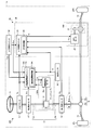
- FIG. 1 is a diagram illustrating a configuration example of a vehicle steering control device according to the first embodiment.
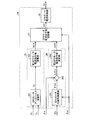
- FIG. 2 is a diagram illustrating an example of an internal functional configuration of the EPS control unit of the vehicle steering control device according to the first embodiment.
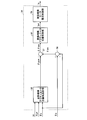
- FIG. 3 is a diagram illustrating an example of an internal functional configuration of the differential mechanism control unit of the vehicle steering control device according to the first embodiment.
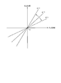
- FIG. 4 is a diagram illustrating a relationship between the pinion angle ⁇ p and the steering angle ⁇ s in the vehicle steering control device according to the first embodiment.
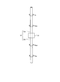
- FIG. 5 is a diagram illustrating an example of torque acting on the steering shaft in the second steering assist mode of the vehicle steering control device according to the first embodiment.
- FIG. 7 is a diagram illustrating a configuration example of the vehicle steering control device according to the second embodiment.
- FIG. 8 is a diagram illustrating an example of an internal functional configuration of the differential mechanism control unit of the vehicle steering control device according to the second embodiment.
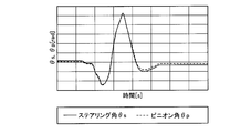
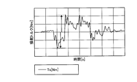
- FIG. 9A is a diagram illustrating a transition example when the steering angle displacement suppression control by the torque control is not applied in the second steering assist mode of the vehicle steering control device according to the second embodiment.
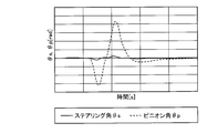
- FIG. 9B is a diagram illustrating a transition example when steering angle displacement suppression control by torque control is applied in the second steering assist mode of the vehicle steering control device according to the second embodiment.
- FIG. 1 is a diagram illustrating a configuration example of a vehicle steering control device according to the first embodiment.
- the left steering wheel 2 ⁇ / b> FL and the right steering wheel 2 ⁇ / b> FR that are left and right steered wheels are steered by steering the steering wheel 11 by the driver and control by the vehicle steering control device 3.
- the steering wheel 11, the left steering wheel 2FL, and the right steering wheel 2FR are connected via a steering shaft 12, a rack and pinion 18, and a tie rod 19 to constitute a steering mechanism 100.
- the rack and pinion 18 includes a pinion 18a and a rack 18b, and steering-drives the left steering wheel 2FL and the right steering wheel 2FR connected to both ends of the rack 18b via tie rods 19, respectively.
- the steering shaft 12 includes a steering shaft 12a on the steering wheel 11 side and a pinion shaft 12b on the rack and pinion 18 side.
- the steering shaft 12a and the pinion shaft 12b are mechanically connected via a differential mechanism 31 described later. It is connected to the.
- the steering shaft 12a and the pinion shaft 12b may be configured by connecting a plurality of torsion bars via a universal joint.
- the first angle sensor 14 is provided on the pinion shaft 12b.
- the first angle sensor 14 detects a pinion angle ⁇ p that is a mechanical angle of the pinion shaft 12b.
- the first angle sensor 14 can be constituted by, for example, an absolute angle sensor, a relative angle sensor, a resolver, or the like.
- an absolute angle sensor a relative angle sensor
- a resolver a resolver
- a second angle sensor 15 is provided on the steering shaft 12a.
- the second angle sensor 15 detects a steering angle ⁇ s that is a mechanical angle of the steering shaft 12a.
- the second angle sensor 15 can be constituted by, for example, an absolute angle sensor, a relative angle sensor, a resolver, or the like.
- the second angle sensor 15 is constituted by a relative angle sensor, a resolver, or the like, it is necessary to obtain the steering angle ⁇ s by converting it to an absolute angle at a later stage.
- a torque sensor 13 is provided on the steering shaft 12a.
- the torque sensor 13 detects a steering torque Ts applied to the steering shaft 12a.
- the vehicle steering control device 3 includes an electric power steering (EPS) device 20 and a differential device 30.
- EPS electric power steering
- the vehicle steering control device 3 avoids a collision between the vehicle 1 and an obstacle, for example, as the operation mode, a first steering assist mode that assists the driver's steering during normal steering of the vehicle 1.
- a second steering assist mode is provided for performing automatic steering independently of driver steering during emergency avoidance steering or the like.
- the vehicle steering control device 3 is switched from the first steering assist mode to the second steering assist mode when the target pinion angle ⁇ p * is input from the automatic steering control unit (superordinate control unit) 50.
- the vehicle steering control device 3 receives a signal for switching between the first steering assist mode and the second steering assist mode in addition to the target pinion angle ⁇ p * from the automatic steering control unit (superordinate control unit) 50. It may be configured. Further, the automatic steering control unit (superordinate control unit) 50 can seamlessly switch between the first steering assist mode and the second steering assist mode based on information from various sensors such as an obstacle detection sensor (not shown). Shall. For example, when the obstacle sensor detects an obstacle in the traveling direction of the vehicle 1, the second steering assist mode is turned on.
- the EPS device 20 is a so-called rack assist type electric power steering device that applies auxiliary force to the rack 18b.
- the EPS device 20 includes a speed reduction mechanism 21, an EPS motor 22, and an EPS control unit 23.
- the speed reduction mechanism 21 and the EPS motor 22 constitute an EPS actuator 200.
- the present invention is not limited by the configuration of the speed reduction mechanism 21 and the configuration of the EPS motor 22.
- the EPS control unit 23 includes EPS control means (first control means) 24 that controls the speed reduction mechanism 21.
- the EPS control means 24 performs current control for giving a desired assist torque to the steering shaft 12 in the first steering assist mode, and gives the EPS motor current Im to the EPS motor 22. Further, the EPS control unit 23 performs current control based on the target pinion angle ⁇ p * from the host control unit 50 and the steering torque Ts detected by the torque sensor 13 in the second steering assist mode, and controls the EPS motor 22 to EPS.
- a motor current Im is given.
- an angular displacement hereinafter referred to as “EPS actuator angle”
- ⁇ eps corresponding to the angular acceleration of the EPS motor 22 occurs in the pinion shaft 12b.
- the differential device 30 includes a differential mechanism 31, a differential mechanism motor 32, and a differential mechanism control unit 33.
- the differential mechanism 31 and the differential mechanism motor 32 constitute a differential mechanism actuator 300.
- the differential mechanism 31 may be, for example, a rudder angle ratio variable mechanism, or may have a structure such as a torque limiter or an electromagnetic clutch.
- the present invention is not limited by the configurations of the differential mechanism 31 and the differential mechanism motor 32.
- the differential mechanism control unit 33 includes a differential mechanism control means (second control means) 34 for controlling the differential mechanism 31.
- the differential mechanism control means 34 controls the current of the differential mechanism motor 32 so that the differential mechanism 31 provided between the pinion shaft 12b and the steering shaft 12a causes an angular difference (hereinafter referred to as “differential mechanism actuator angle”). ⁇ dm) is generated.
- the differential mechanism control means 34 will be described later.
- FIG. 2 is a diagram illustrating an example of an internal functional configuration of the EPS control unit of the vehicle steering control device according to the first embodiment.
- the EPS control means 24 includes an EPS assist control unit 25, an EPS motor angle control unit 26, an EPS motor current command value switching unit 27, and an EPS motor current control unit 28.
- the EPS control means 24 includes a vehicle speed Vt detected by the vehicle speed sensor 16, a pinion angle ⁇ p detected by the first angle sensor 14, a steering torque Ts detected by the torque sensor 13, and an EPS motor angle ⁇ m from the EPS motor 22.
- the target pinion angle ⁇ p * from the automatic steering control unit (upper control unit) 50 is input.
- the EPS assist control unit 25 includes an EPS motor assist torque calculation unit 251 and a first EPS motor current command value calculation unit 252.
- the EPS motor assist torque calculation unit 251 obtains the assist torque Ta as the EPS actuator 200 based on the vehicle speed Vt and the steering torque Ts in the first steering assist mode, and outputs the assist torque Ta to the first EPS motor current command value calculation unit 252.
- the first EPS motor current command value calculation unit 252 obtains a current command value (first EPS motor current command value) Im1 * of the EPS motor 22 necessary for obtaining the assist torque Ta, and outputs it to the EPS motor current command value switching unit 27. To do.
- the EPS motor angle control unit 26 includes an EPS motor target angle calculation unit 261, an adder 262, and a second EPS motor current command value calculation unit 263.
- the EPS motor target angle calculation unit 261 obtains the EPS motor target angle ⁇ m * required in the second steering assist mode based on the target pinion angle ⁇ p * and the pinion angle ⁇ p in the second steering assist mode. More specifically, the EPS motor target angle calculation unit 261 calculates an angle deviation of the pinion angle ⁇ p with respect to the target pinion angle ⁇ p *, and calculates an EPS actuator target angle ⁇ eps * necessary for canceling the angle deviation. Then, the EPS motor target angle calculation unit 261 calculates an EPS motor target angle ⁇ m * corresponding to the calculated EPS actuator target angle ⁇ eps *, and outputs it to the adder 262.
- the adder 262 calculates an angle deviation ⁇ m between the EPS motor target angle ⁇ m * and the EPS motor angle ⁇ m, and outputs it to the second EPS motor current command value calculation unit 263.
- the second EPS motor current command value calculation unit 263 is a current command value (second EPS motor current command value) Im2 of the EPS motor 22 necessary for canceling the angle deviation ⁇ m between the EPS motor target angle ⁇ m * and the EPS motor angle ⁇ m. * Is obtained and output to the EPS motor current command value switching unit 27.
- the EPS motor current command value switching unit 27 is configured to output a first EPS motor current command value Im1 * output from the EPS assist control unit 25 and a second EPS motor output from the EPS motor angle control unit 26 according to the target pinion angle ⁇ p *.
- the current command value Im2 * is switched and output as the EPS motor current command value Im *. More specifically, if the target pinion angle ⁇ p * is not input from the automatic steering control unit (upper control unit) 50, the EPS motor current command value switching unit 27 is assumed to be in the first steering assist mode.
- the 1 EPS motor current command value Im1 * is output to the EPS motor current control unit 28 as the EPS motor current command value Im *.
- the EPS motor current command value switching unit 27 assumes that the second steering motor assist mode is in the second steering assist mode.
- the value Im2 * is output to the EPS motor current control unit 28 as the EPS motor current command value Im *.
- the EPS motor current control unit 28 generates an EPS motor current Im corresponding to the EPS motor current command value Im * output from the EPS motor current command value switching unit 27 and supplies the EPS motor current Im to the EPS motor 22.
- the EPS control means 24 controls the torque of the EPS actuator 200 by controlling the current of the EPS motor 22 so that the assist torque Ta corresponding to the steering torque Ts at the vehicle speed Vt is obtained in the first steering assist mode. Do. Further, the EPS control means 24 controls the current of the EPS motor 22 so as to follow the target pinion angle ⁇ p * input from the automatic steering control unit (superordinate control unit) 50 in the second steering assist mode. The angle control of the EPS actuator 200 is performed.
- FIG. 3 is a diagram illustrating an example of an internal functional configuration of the differential mechanism control unit of the vehicle steering control device according to the first embodiment.
- the differential mechanism control means 34 includes a differential mechanism actuator target angle calculation unit 35, adders 36 and 37, a differential mechanism actuator position control unit 38, and a differential mechanism motor current control unit 39.
- the differential mechanism control means 34 includes a pinion angle ⁇ p detected by the first angle sensor 14, a steering angle ⁇ s detected by the second angle sensor 15, a vehicle speed Vt detected by the vehicle speed sensor 16, and an automatic steering control unit.
- the target pinion angle ⁇ p * from the (upper control unit) 50 is input.
- the differential mechanism control means 34 in the present embodiment realizes steering assist control according to the vehicle speed Vt, and in the second steering assist mode, the differential mechanism actuator 300 is angle-controlled. Steering angle displacement suppression control that suppresses the angular displacement that occurs in the steering angle ⁇ s is realized.
- the differential mechanism actuator target angle calculation unit 35 determines an angle command in the differential mechanism actuator 300 based on the vehicle speed Vt, the steering angle ⁇ s, and the target pinion angle ⁇ p *, that is, the differential mechanism actuator target.
- the differential mechanism actuator target angle ⁇ dm * in the angle calculator 35 is obtained and output to the adder 37.
- the differential mechanism actuator target angle calculation unit 35 obtains the differential mechanism actuator target angle ⁇ dm * based on the steering angle ⁇ s and outputs it to the adder 37 in the second steering assist mode.
- the adder 36 obtains a relative difference between the pinion angle ⁇ p and the steering angle ⁇ s and outputs it to the adder 37.
- the relative difference between the pinion angle ⁇ p and the steering angle ⁇ s is the differential mechanism actuator angle ⁇ dm in the differential mechanism actuator 300.
- the adder 37 obtains an angle deviation ⁇ dm between the differential mechanism actuator target angle ⁇ dm * output from the differential mechanism actuator target angle calculator 35 and the differential mechanism actuator angle ⁇ dm output from the adder 36, and calculates the difference. This is output to the moving mechanism actuator position controller 38.
- the differential mechanism actuator position control unit 38 controls the position of the differential mechanism actuator 300 based on the angle deviation ⁇ dm between the differential mechanism actuator target angle ⁇ dm * and the differential mechanism actuator angle ⁇ dm. That is, the differential mechanism actuator position control unit 38 determines the current command value (difference) of the differential mechanism motor 32 necessary to cancel the angle deviation ⁇ dm between the differential mechanism actuator target angle ⁇ dm * and the differential mechanism actuator angle ⁇ dm.
- the dynamic mechanism motor current command value) Ia * is obtained and output to the differential mechanism motor current control unit 39.
- the differential mechanism motor current control unit 39 generates a differential mechanism motor current Ia corresponding to the differential mechanism motor current command value Ia * output from the differential mechanism actuator position control unit 38 and supplies the differential mechanism motor current Ia to the differential mechanism motor 32. give.
- FIG. 4 is a diagram illustrating a relationship between the pinion angle ⁇ p and the steering angle ⁇ s in the vehicle steering control device according to the first embodiment.
- the horizontal axis indicates the phase of the steering angle ⁇ s
- the vertical axis indicates the phase of the pinion angle ⁇ p.
- the right direction indicates the right turning direction of the steering wheel 11
- the left direction indicates the left turning direction of the steering wheel 11.
- the upward direction indicates the right steering direction of each steered wheel 2FL, 2FR
- the downward direction indicates the left steered direction of each steered wheel 2FL, 2FR.
- An example represented by a linear line having a proportional relationship with a slope of is shown.
- the pinion angle ⁇ p and the steering angle ⁇ s are linear lines having a proportional relationship with a positive slope.
- the configuration is always a cubic curve with a zero to positive slope. It may be.
- ⁇ is the ratio of the pinion angle ⁇ p to the steering angle ⁇ s.
- the ratio ⁇ of the pinion angle ⁇ p to the steering angle ⁇ s can be set to an arbitrary value larger than zero.
- the former is suitable for low-speed traveling, and the latter is suitable for high-speed traveling. That is, in the first steering assist mode, it is desirable to change the ratio ⁇ of the pinion angle ⁇ p to the steering angle ⁇ s according to the vehicle speed Vt.
- the differential mechanism actuator angle ⁇ dm in the differential mechanism actuator 300 is superimposed. At this time, if the ratio of the steering angle ⁇ s and the pinion angle ⁇ p determined by the differential mechanism 31 is ⁇ and the ratio of the steering angle ⁇ s and the differential mechanism actuator angle ⁇ dm determined by the differential mechanism 31 is ⁇ , the following (2 ) Formula is obtained.
- the ratio ⁇ between the steering angle ⁇ s and the pinion angle ⁇ p and the ratio ⁇ between the steering angle ⁇ s and the differential mechanism actuator angle ⁇ dm are constant values determined by the differential mechanism 31.
- the right side in the above equation (3) is the angle command in the differential mechanism actuator 300, that is, the differential mechanism actuator target angle ⁇ dm * in the differential mechanism actuator target angle calculation unit 35.
- the steering shaft 12a is an input shaft of the differential mechanism 31, and the pinion shaft 12b is an output shaft of the differential mechanism 31. That is, the steering angle ⁇ s is input to the differential mechanism 31 and the pinion angle ⁇ p is output.
- the EPS actuator 200 is angularly controlled to cause an angular displacement in the pinion shaft 12b.
- the pinion shaft 12b becomes an input shaft of the differential mechanism 31, and the steering shaft 12a of the differential mechanism 31 becomes an output shaft. That is, the pinion angle ⁇ p is input to the differential mechanism 31 and the steering angle ⁇ s is output. Therefore, when the above equations (1) and (2) are modified as the steering angle ⁇ s, the following equations (4) and (5) are obtained.
- the steering angle ⁇ s is the reciprocal of the ratio ⁇ of the pinion angle ⁇ p to the steering angle ⁇ s with respect to the pinion angle ⁇ p, that is, the ratio of the steering angle ⁇ s to the pinion angle ⁇ p.
- the value is multiplied by / ⁇ . Accordingly, in the second steering assist mode, if the ratio 1 / ⁇ of the steering angle ⁇ s to the pinion angle ⁇ p is reduced, that is, if the ratio ⁇ of the pinion angle ⁇ p to the steering angle ⁇ s is increased, the steering wheel 11 Steering angular displacement suppression control that suppresses the generated angular displacement (steering angular displacement) can be realized.
- the differential mechanism actuator target angle calculation unit 35 sets the first ratio ⁇ 1 of the pinion angle ⁇ p to the steering angle ⁇ s to the above equation (3). To obtain the differential mechanism actuator target angle ⁇ dm *.
- the differential mechanism actuator target angle calculation unit 35 sets the second ratio ⁇ 2 set according to the arbitrary vehicle speed Vt (3 ) To obtain the differential mechanism actuator target angle ⁇ dm *.
- the angle of the differential mechanism actuator 300 is controlled by the first ratio ⁇ 1 of the pinion angle ⁇ p with respect to the steering angle ⁇ s, and in the first steering assist mode, the difference is determined by the second ratio ⁇ 2 corresponding to the vehicle speed Vt.
- the moving mechanism actuator 300 is angle-controlled.
- the steering angle displacement suppression control in which the angular displacement of the steering angle ⁇ s is made smaller than the angular displacement of the pinion angle ⁇ p.
- the vehicle speed Vt is increased. Accordingly, appropriate steering assist control can be realized.
- FIG. 5 is a diagram illustrating an example of torque acting on the steering shaft in the second steering assist mode of the vehicle steering control device according to the first embodiment.
- the steering shaft 12 is proportional to the steering torque Ts, the differential mechanism actuator torque Tdm generated by the differential mechanism actuator 300, and the inertia applied by the EPS device 20 that is angle-controlled in the second steering assist mode.
- the EPS actuator 200 is subjected to angle control to generate an EPS actuator torque Teps in which an acceleration proportional to the inertia is converted.
- the EPS actuator torque Teps is a pinion shaft 12b, a differential mechanism. 31 is transmitted to the steering wheel 11 via the steering shaft 12a.
- the pinion shaft 12b can be an input shaft of the differential mechanism 31, and the steering shaft 12a can be an output shaft of the differential mechanism 31.
- Steering torque Ts, differential mechanism actuator torque Tdm, EPS actuator torque Teps, and self-aligning torque Tsa are expressed by the following equation (6).
- Ts + Tdm Teps + Tsa (6)
- Ts (Teps + Tsa) ⁇ Tdm (7)
- the torque (Teps + Tsa) obtained by adding the EPS actuator torque Teps generated by the EPS device 20 and the self-aligning torque Tsa in the second steering assist mode is obtained by the differential mechanism actuator 300.
- Ts + Tdm ⁇ (Teps + Tsa) Jh ⁇ d2 ⁇ h / dt (8)
- the steering wheel 11 is caused by each torque including the steering torque Ts generated on the steering shaft 12, the differential mechanism actuator torque Tdm, the EPS actuator torque Teps, and the self-aligning torque Tsa.
- the resulting angular displacement ⁇ h will occur.
- the steering angle ⁇ s is obtained by adding the EPS actuator torque Teps generated by the EPS device 20 and the self-aligning torque Tsa in the second steering assist mode.
- the torque (Teps + Tsa) can be suppressed by canceling with the differential mechanism actuator torque Tdm that can be generated by the differential mechanism actuator 300.
- the angular displacement of the steering angle ⁇ s in the second steering assist mode can be suppressed using the differential mechanism actuator torque Tdm.
- the differential mechanism control unit 34 of the vehicle steering control device 3 reduces the angular displacement of the steering angle ⁇ s relative to the angular displacement of the pinion angle ⁇ p.
- the differential mechanism actuator 300 is angle-controlled by applying the first ratio ⁇ 1 of the pinion angle ⁇ p to the steering angle ⁇ s.
- the differential mechanism actuator 300 cancels the EPS actuator torque Teps applied by the EPS device 20 in the second steering assist mode, that is, the pinion angle ⁇ p applied to the steering shaft 12 by the EPS actuator torque Teps.
- the differential mechanism actuator angle ⁇ dm is given in the direction opposite to the EPS actuator torque Teps.
- a differential mechanism actuator angle ⁇ dm opposite to the pinion angle ⁇ p generated by the EPS actuator torque Teps is generated.
- the angular displacement of the steering angle ⁇ s is suppressed, and the EPS device 20 performs the second steering assist mode.
- the influence of the generated torque (EPS actuator torque Teps) on the steering of the steering wheel 11 by the driver can be suppressed. That is, in the vehicle steering control device 3 according to the present embodiment, in the second steering assist mode, it is possible to realize the steering angle displacement suppression control in which the angular displacement of the steering angle ⁇ s is smaller than the angular displacement of the pinion angle ⁇ p. it can.
- the differential mechanism control means 34 of the vehicle steering control device 3 applies the second ratio ⁇ 2 set according to an arbitrary vehicle speed Vt in the first steering assist mode, and performs differential operation.
- the angle of the mechanism actuator 300 is controlled.
- appropriate steering assist control according to the vehicle speed Vt can be realized in the first steering assist mode.
- simulation is performed assuming that an obstacle ahead of the vehicle is avoided in the second steering assist mode.
- the steering wheel 11 and the rack and pinion 18 that steers the steering wheels 2FL and 2FR are connected via the differential mechanism 31.
- the vehicle steering control device 3 assists the driver's steering as the operation modes of the EPS control means (first control means) 24 and the differential mechanism control means (second control means) 34.
- the differential mechanism control means (second control means) 34 is connected to the pinion shaft 12b (differential mechanism) of the steering shaft 12 from the speed reduction mechanism 21 controlled by the EPS control means (first control means) 24 in the second steering assist mode.
- the differential mechanism 31 is angle-controlled so as to cancel the angular displacement caused by the torque applied to the rack and pinion 18 side of 31.
- the differential mechanism control means (second control means) 34 performs differential operation so that the angular displacement of the steering angle ⁇ s is smaller than the angular displacement of the pinion angle ⁇ p in the second steering assist mode.
- the mechanism 31 is angle-controlled.
- the differential mechanism 31 of the differential mechanism actuator 300 is applied to the steering shaft 12 in the direction in which the EPS actuator torque Teps applied by the speed reducer 21 of the EPS device 20 is canceled in the second steering assist mode, that is, by the EPS actuator torque Teps.
- a differential mechanism actuator angle ⁇ dm opposite to the EPS actuator torque Teps is given so as to cancel the given pinion angle ⁇ p.
- a differential mechanism actuator angle ⁇ dm opposite to the pinion angle ⁇ p generated by the EPS actuator torque Teps is generated.
- the angular displacement of the steering angle ⁇ s is suppressed, and the EPS device 20 performs the second steering assist mode.
- the influence of the generated torque (EPS actuator torque Teps) on the steering of the steering wheel 11 by the driver can be suppressed.
- the differential mechanism control means (second control means) 34 has a steering angle ⁇ s (the steering wheel 11 of the differential mechanism 31) with respect to the pinion angle ⁇ p (an angle on the rack and pinion 18 side of the differential mechanism 31). 1st ratio is set, and the angle of the differential mechanism 31 is controlled based on (the angle on the steering wheel 11 side of the differential mechanism 31) and the first ratio of the steering angle ⁇ s to the pinion angle ⁇ p.
- the angular displacement caused by the torque applied from the speed reduction mechanism 21 controlled by the EPS control means (first control means) 24 to the pinion shaft 12b of the steering shaft 12 (the rack and pinion 18 side of the differential mechanism 31) is canceled out. Can do.
- the differential mechanism control means (second control means) 34 is set in accordance with the steering angle ⁇ s (the angle on the steering wheel 11 side of the differential mechanism 31) and the vehicle speed Vt in the first steering assist mode.
- the differential mechanism 31 is angle-controlled based on the second ratio. That is, the angle of the differential mechanism 31 is controlled by switching between the first ratio and the second ratio in the second steering assist mode and the first steering assist mode.
- the steering angle displacement suppression control in which the angular displacement of the steering angle ⁇ s is made smaller than the angular displacement of the pinion angle ⁇ p.
- the vehicle speed Vt is increased. Accordingly, appropriate steering assist control can be realized.
- the EPS control unit (first control unit) 24 is included in the EPS control unit 23, and the differential mechanism control unit (second control unit) 34 is included in the differential mechanism control unit 33.
- the EPS control means (first control means) 24 and the differential mechanism control means (second control means) 34 may be configured to be included in the same control unit,
- the EPS control unit 23 and the differential mechanism control unit 33 may be configured as one control unit.
- the present invention is not limited by the configuration of these control units and the physical configuration of the EPS control means (first control means) 24 and the differential mechanism control means (second control means) 34.
- FIG. 7 is a diagram illustrating a configuration example of the vehicle steering control device according to the second embodiment.
- the configuration of the EPS control means 24 of the vehicle steering control device according to the second embodiment is the same as that of the first embodiment described above, and thus the description thereof is omitted here.
- the vehicle steering control device 3a is switched from the first steering assist mode to the second steering assist mode when the target pinion angle ⁇ p * and the target steering torque Ts * are input from the automatic steering control unit (upper control unit) 50. .
- the vehicle steering control device 3a performs the first steering assist mode and the second steering assist mode in addition to the target pinion angle ⁇ p * and the target steering torque Ts *.
- a configuration in which a signal for switching is input may be used.
- the differential device 30a includes a differential mechanism 31, a differential mechanism motor 32a, and a differential mechanism control unit 33a.
- the differential mechanism 31 and the differential mechanism motor 32a constitute a differential mechanism actuator 300a.
- the differential mechanism control unit 33a includes a differential mechanism control means (second control means) 34a for controlling the differential mechanism 31.
- the differential mechanism control means 34a controls the current of the differential mechanism motor 32a, so that an angle difference ⁇ dm is generated by the differential mechanism 31 provided between the pinion shaft 12b and the steering shaft 12a.
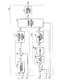
- FIG. 8 is a diagram illustrating an example of an internal functional configuration of the differential mechanism control unit of the vehicle steering control device according to the second embodiment.
- the differential mechanism control means 34a includes a first differential mechanism motor command value generation unit 45, a second differential mechanism motor command value generation unit 46, a differential mechanism motor current command value switching unit 47, and a differential mechanism motor. And a current control unit 48.
- the first differential mechanism motor command value generation unit 45 includes a differential mechanism motor target angle calculation unit 451, an adder 452, and a first differential mechanism motor current command value calculation unit 453.
- the second differential mechanism motor command value generation unit 46 includes an adder 461, a differential mechanism actuator torque command value calculation unit 462, and a second differential mechanism motor current command value calculation unit 463.
- the differential mechanism actuator torque command value calculation unit 462 includes, for example, a phase compensator 464 and a control unit 465.
- the control unit 465 may be a PI control unit or a P control unit, for example.
- the differential mechanism control means 34a includes a vehicle speed Vt detected by the vehicle speed sensor 16, a steering angle ⁇ s detected by the second angle sensor 15, an absolute angle (differential mechanism motor angle) ⁇ a of the differential mechanism motor 32a, torque The steering torque Ts detected by the sensor 13, the target pinion angle ⁇ p * from the automatic steering control unit (upper control unit) 50, and the target steering torque Ts * are input.
- the differential mechanism control unit 34a realizes steering assist control according to the vehicle speed Vt, and in the second steering assist mode, the EPS actuator 200 is torque-controlled to thereby control the steering angle. Steering angular displacement suppression control that suppresses the angular displacement that occurs in ⁇ s is realized.
- the differential mechanism motor target angle calculation unit 451 of the first differential mechanism motor command value generation unit 45 in the first steering assist mode, based on the vehicle speed Vt and the steering angle ⁇ s, the angle command (differential) in the differential mechanism actuator 300a.
- the mechanism actuator target angle ⁇ dm *) is obtained.
- the differential mechanism motor target angle calculation unit 451 calculates a differential mechanism motor target angle ⁇ a * corresponding to the calculated differential mechanism actuator target angle ⁇ dm *, and outputs it to the adder 452.
- the adder 452 obtains an angle deviation ⁇ a between the differential mechanism motor target angle ⁇ a * output from the differential mechanism motor target angle calculation unit 451 and the differential mechanism motor angle ⁇ a, and calculates a first differential mechanism motor current command. The result is output to the value calculation unit 453.
- the first differential mechanism motor current command value calculation unit 453 is a current command value for the differential mechanism motor 32a that is necessary to cancel out the angle deviation ⁇ a between the differential mechanism motor target angle ⁇ a * and the differential mechanism motor angle ⁇ a. (First differential mechanism motor current command value) Ia1 * is obtained and output to the differential mechanism motor current command value switching unit 47.
- the adder 461 of the second differential mechanism motor command value generation unit 46 is detected by the target steering torque Ts * from the automatic steering control unit (upper control unit) 50 and the torque sensor 13 in the second steering assist mode.
- the deviation ⁇ Ts from the steering torque Ts thus obtained is obtained and output to the differential mechanism actuator torque command value calculation unit 462.
- the differential mechanism actuator torque command value calculation unit 462 obtains the differential mechanism actuator torque command value Tdm * based on the deviation ⁇ Ts between the target steering torque Ts * and the steering torque Ts input from the adder 461 and obtains the second difference. This is output to the moving mechanism motor current command value calculation unit 463.
- the differential mechanism actuator torque command value calculation unit 462 including the phase compensator 464 and the control unit 465 is illustrated.
- the differential mechanism actuator torque command value calculation unit 462 is illustrated.
- the present invention is not limited to the configuration of the differential mechanism actuator torque command value calculation unit 462.
- the second differential mechanism motor current command value calculation unit 463 is a current command value (second differential mechanism motor current command value) Ia2 of the differential mechanism motor 32a necessary for obtaining the differential mechanism actuator torque command value Tdm *. * Is obtained and output to the differential mechanism motor current command value switching unit 47.
- the differential mechanism motor current command value switching unit 47 corresponds to the first differential mechanism motor current command value Ia1 * output from the first differential mechanism motor current command value calculation unit 453 according to the target pinion angle ⁇ p *.
- the second differential mechanism motor current command value Ia2 * output from the differential mechanism motor current command value calculation unit 463 is switched and output as the differential mechanism motor current command value Ia *. More specifically, if the target pinion angle ⁇ p * is not input from the automatic steering control unit (upper control unit) 50, the differential mechanism motor current command value switching unit 47 is assumed to be in the first steering assist mode.
- the first differential mechanism motor current command value Ia1 * is output to the differential mechanism motor current control unit 48 as the differential mechanism motor current command value Ia *.
- the differential mechanism motor current command value switching unit 47 is assumed to be in the second steering assist mode, and the second difference
- the dynamic mechanism motor current command value Ia2 * is output to the differential mechanism motor current control unit 48 as the differential mechanism motor current command value Ia *.
- the differential mechanism motor current control unit 48 generates a differential mechanism motor current Ia corresponding to the differential mechanism motor current command value Ia * output from the differential mechanism motor current command value switching unit 47 to generate a differential mechanism motor. 32a.
- the differential mechanism control unit 34a of the vehicle steering control device 3a applies the ratio ⁇ of the pinion angle ⁇ p to the steering angle ⁇ s according to the vehicle speed Vt, so that the differential mechanism The angle of the actuator 300a is controlled. Further, the differential mechanism control means 34a is configured so that, in the second steering assist mode, the deviation ⁇ Ts between the target steering torque Ts * and the steering torque Ts given from the automatic steering control unit (upper control unit) 50 becomes small. Torque control is performed on the differential mechanism actuator 300a.
- the differential mechanism actuator 300a cancels the EPS actuator torque Teps given by the speed reducer 21 of the EPS device 20, that is, the pinion angle ⁇ p given to the steering shaft 12 by the EPS actuator torque Teps. Is given a differential mechanism actuator angle ⁇ dm opposite to the EPS actuator torque Teps. As a result, a differential mechanism actuator angle ⁇ dm opposite to the pinion angle ⁇ p generated by the EPS actuator torque Teps is generated. As a result, the angular displacement of the steering angle ⁇ s is suppressed, and the EPS device 20 performs the second steering assist mode. The influence of the generated torque (EPS actuator torque Teps) on the steering of the steering wheel 11 by the driver can be suppressed.
- EPS actuator torque Teps The influence of the generated torque (EPS actuator torque Teps) on the steering of the steering wheel 11 by the driver can be suppressed.
- FIG. 9A is a diagram illustrating a transition example when the steering angle displacement suppression control by the torque control is not applied in the second steering assist mode of the vehicle steering control device according to the second embodiment.
- FIG. 9B is a diagram illustrating a transition example when steering angle displacement suppression control by torque control is applied in the second steering assist mode of the vehicle steering control device according to the second embodiment.
- simulation is performed assuming that an obstacle ahead of the vehicle is avoided in the second steering assist mode.
- the steering angle displacement suppression control by torque control according to the second embodiment when the steering angle displacement suppression control by torque control according to the second embodiment is applied, the steering angle displacement suppression control by torque control according to the second embodiment is not applied (FIG. 9A).
- the amplitude of the steering torque Ts is smaller than that. That is, in the vehicle steering control device 3a according to the present embodiment, the target steering torque Ts * input from the automatic steering control unit (upper control unit) 50 is appropriately set, and the EPS device 20 is in the first steering assist mode.
- ⁇ dm it is possible to suppress the influence of the torque generated by the EPS device 20 during the second steering assist mode on the steering of the steering wheel 11 by the driver.
- the target steering torque Ts * is described as being given from the automatic steering control unit (superordinate control unit) 50.
- the target steering torque Ts * is set in advance in the second differential mechanism motor command value generation unit 46 as a set value. Or stored in a storage unit (not shown) provided in the differential mechanism control unit 33a to generate a second differential mechanism motor command value when switching from the first steering assist mode to the second steering assist mode. It may be configured to be read by the unit 46.
- the differential mechanism control means (second control means) 34a of the vehicle steering control device 3a is operated by the EPS control means (first control means) 24 in the second steering assist mode.
- the differential mechanism 31 is torque-controlled so as to cancel the torque applied from the controlled speed reduction mechanism 21 to the pinion shaft 12b of the steering shaft 12 (the rack and pinion 18 side of the differential mechanism 31).
- the differential mechanism 31 of the differential mechanism actuator 300a is applied to the steering shaft 12 in the direction in which the EPS actuator torque Teps given by the speed reducer 21 of the EPS device 20 is canceled in the second steering assist mode, that is, by the EPS actuator torque Teps.
- a differential mechanism actuator angle ⁇ dm opposite to the EPS actuator torque Teps is given so as to cancel the given pinion angle ⁇ p.
- a differential mechanism actuator angle ⁇ dm opposite to the pinion angle ⁇ p generated by the EPS actuator torque Teps is generated.
- the angular displacement of the steering angle ⁇ s is suppressed, and the EPS device 20 performs the second steering assist mode.
- the influence of the generated torque (EPS actuator torque Teps) on the steering of the steering wheel 11 by the driver can be suppressed.
- the differential mechanism control means (second control means) 34a controls the torque of the differential mechanism 31 so that the steering torque Ts generated in the steering wheel 11 becomes the predetermined target steering torque Ts *.
- the torque applied to the rack and pinion 18 side of the differential mechanism 31 from the speed reduction mechanism 21 controlled by the EPS control means (first control means) 24 can be canceled out.
- the EPS control unit (first control means) 24 is included in the EPS control unit 23, and the differential mechanism control means (second control means) 34a is included in the differential mechanism control unit 33a.
- the EPS control means (first control means) 24 and the differential mechanism control means (second control means) 34a may be included in the same control unit,
- the EPS control unit 23 and the differential mechanism control unit 33a may be configured as one control unit.
- the present invention is not limited by the configuration of these control units and the physical configuration of the EPS control means (first control means) 24 and the differential mechanism control means (second control means) 34a.
Landscapes
- Engineering & Computer Science (AREA)
- Chemical & Material Sciences (AREA)
- Combustion & Propulsion (AREA)
- Transportation (AREA)
- Mechanical Engineering (AREA)
- Physics & Mathematics (AREA)
- Mathematical Physics (AREA)
- Steering Control In Accordance With Driving Conditions (AREA)
- Power Steering Mechanism (AREA)
Abstract
Description
図1は、実施形態1に係る車両用ステアリング制御装置の一構成例を示す図である。図1に示す例において、車両1は、左右の転舵輪となる左操舵輪2FL及び右操舵輪2FRが、運転者によるステアリングホイール11の操舵及び車両用ステアリング制御装置3による制御によって転舵される。ステアリングホイール11と左操舵輪2FL及び右操舵輪2FRとの間は、操舵軸12と、ラックアンドピニオン18と、タイロッド19とを介して連結され、ステアリング機構100が構成されている。
図7は、実施形態2に係る車両用ステアリング制御装置の一構成例を示す図である。なお、図7に示す車両1aにおいて、実施形態2に係る車両用ステアリング制御装置のEPS制御手段24の構成は、上述した実施形態1と同様であるので、ここでは説明を省略する。
2FL 左操舵輪
2FR 右操舵輪
3,3a 車両用ステアリング制御装置
11 ステアリングホイール
12 操舵軸
12a ステアリングシャフト
12b ピニオンシャフト
13 トルクセンサ
14 第1角度センサ
15 第2角度センサ
16 車速センサ
18 ラックアンドピニオン
18a ピニオン
18b ラック
19 タイロッド
20 EPS装置
21 減速機構
22 EPSモータ
23 EPS制御ユニット
24 EPS制御手段(第1制御手段)
25 EPSアシスト制御部
26 EPSモータ角制御部
27 EPSモータ電流指令値切替部
28 EPSモータ電流制御部
30,30a 差動装置
31 差動機構
32,32a 差動機構モータ
33,33a 差動機構制御ユニット
34,34a 差動機構制御手段(第2制御手段)
35 差動機構アクチュエータ目標角演算部
36 加算器
37 加算器
38 差動機構アクチュエータ位置制御部
39 差動機構モータ電流制御部
45 第1差動機構モータ指令値生成部
46 第2差動機構モータ指令値生成部
47 差動機構モータ電流指令値切替部
48 差動機構モータ電流制御部
50 上位制御ユニット(自動操舵制御ユニット)
100 ステアリング機構
200 EPSアクチュエータ
251 EPSモータアシストトルク演算部
252 第1EPSモータ電流指令値演算部
261 EPSモータ目標角演算部
262 加算器
263 第2EPSモータ電流指令値演算部
300,300a 差動機構アクチュエータ
451 差動機構モータ目標角演算部
452 加算器
453 第1差動機構モータ電流指令値演算部
461 加算器
462 差動機構アクチュエータトルク指令値演算部
463 第2差動機構モータ電流指令値演算部
464 位相補償器
465 制御手段
Ia 差動機構モータ電流
Ia* 差動機構モータ電流指令値
Im EPSモータ電流
Im* EPSモータ電流指令値
Im1* 第1EPSモータ電流指令値
Im2* 第2EPSモータ電流指令値
Ta アシストトルク
Tdm 差動機構アクチュエータトルク
Tdm* 差動機構アクチュエータトルク指令値
Teps EPSアクチュエータトルク
Ts 操舵トルク
Tsa セルフアライニングトルク
Ts* 目標操舵トルク
α ステアリング角θsに対するピニオン角θpの比率
α1 第1比率
α2 第2比率
θa 差動機構モータ角
θa* 差動機構モータ目標角
θdm 差動機構アクチュエータ角
θdm* 差動機構アクチュエータ目標角
θeps EPSアクチュエータ角
θeps* EPSアクチュエータ目標角
θh 角変位
θm EPSモータ角
θm* EPSモータ目標角
θs ステアリング角
θp ピニオン角
θp* 目標ピニオン角
Δθa 角度偏差(差動機構モータ)
Δθm 角度偏差(EPSモータ)
Claims (8)
- ステアリングホイールと、操舵輪を操舵駆動するラックアンドピニオンとの間が差動機構を介して接続され、前記ラックアンドピニオンと前記操舵輪との間に減速機構が設けられたステアリング機構において、前記減速機構を制御する第1制御手段と、
前記ステアリング機構において、前記差動機構を制御する第2制御手段と、
を備え、
前記第1制御手段及び前記第2制御手段の動作モードとして、
運転者の操舵を補助する第1操舵アシストモードと、
運転者の操舵とは独立して操舵を行う第2操舵アシストモードと、
を有し、
前記第2制御手段は、
前記第2操舵アシストモードにおいて、前記第1制御手段によって制御された前記減速機構から前記差動機構の前記ラックアンドピニオン側に与えられたトルクを打ち消すように、前記差動機構を制御する
車両用ステアリング制御装置。 - 前記第2制御手段は、
前記第2操舵アシストモードにおいて、前記ステアリングホイール側の角変位が前記ラックアンドピニオン側の角変位に対して小さくなるように、前記差動機構を制御する
請求項1に記載の車両用ステアリング制御装置。 - 前記第2制御手段は、
前記差動機構の前記ラックアンドピニオン側の角度に対する前記差動機構の前記ステアリングホイール側の角度の第1比率が設定され、前記第2操舵アシストモードにおいて、前記差動機構の前記ステアリングホイール側の角度及び前記第1比率に基づき、前記差動機構を制御する
請求項2に記載の車両用ステアリング制御装置。 - 前記第2制御手段は、
前記差動機構の前記ラックアンドピニオン側の角度に対する前記差動機構の前記ステアリングホイール側の角度の前記第1比率とは異なる第2比率が設定され、前記第1操舵アシストモードにおいて、前記差動機構の前記ステアリングホイール側の角度及び前記第2比率に基づき、前記差動機構を制御する
請求項3に記載の車両用ステアリング制御装置。 - 前記第2制御手段は、
前記第1比率と前記第2比率とを切り替えて、前記差動機構を制御する
請求項4に記載の車両用ステアリング制御装置。 - 前記第2制御手段は、
前記第1操舵アシストモードにおいて、車速に応じて前記第2比率が設定される
請求項4又は請求項5に記載の車両用ステアリング制御装置。 - 前記差動機構の前記ステアリングホイール側のトルクを検出するトルクセンサを備え、
前記第2制御手段は、
前記第2操舵アシストモードにおいて、前記トルクセンサによって検出される操舵トルクが所定の目標操舵トルクとなるように、前記差動機構を制御する
請求項1に記載の車両用ステアリング制御装置。 - 外部からの指令に基づき、前記第1操舵アシストモードと前記第2操舵アシストモードとが切り替えられる
請求項1から請求項7の何れか一項に記載の車両用ステアリング制御装置。
Priority Applications (4)
| Application Number | Priority Date | Filing Date | Title |
|---|---|---|---|
| US16/072,073 US10464605B2 (en) | 2016-02-17 | 2017-02-09 | Vehicle steering control device |
| CN201780010653.XA CN108602530A (zh) | 2016-02-17 | 2017-02-09 | 车辆用转向控制装置 |
| JP2018500077A JP6376307B2 (ja) | 2016-02-17 | 2017-02-09 | 車両用ステアリング制御装置 |
| EP17753077.1A EP3395651B1 (en) | 2016-02-17 | 2017-02-09 | Vehicle steering control device |
Applications Claiming Priority (4)
| Application Number | Priority Date | Filing Date | Title |
|---|---|---|---|
| JP2016-028277 | 2016-02-17 | ||
| JP2016-028276 | 2016-02-17 | ||
| JP2016028277 | 2016-02-17 | ||
| JP2016028276 | 2016-02-17 |
Publications (1)
| Publication Number | Publication Date |
|---|---|
| WO2017141819A1 true WO2017141819A1 (ja) | 2017-08-24 |
Family
ID=59625032
Family Applications (1)
| Application Number | Title | Priority Date | Filing Date |
|---|---|---|---|
| PCT/JP2017/004784 Ceased WO2017141819A1 (ja) | 2016-02-17 | 2017-02-09 | 車両用ステアリング制御装置 |
Country Status (5)
| Country | Link |
|---|---|
| US (1) | US10464605B2 (ja) |
| EP (1) | EP3395651B1 (ja) |
| JP (1) | JP6376307B2 (ja) |
| CN (1) | CN108602530A (ja) |
| WO (1) | WO2017141819A1 (ja) |
Cited By (1)
| Publication number | Priority date | Publication date | Assignee | Title |
|---|---|---|---|---|
| CN109189079A (zh) * | 2018-11-05 | 2019-01-11 | 南京理工大学 | 基于gps定位的移动机器人导航控制方法 |
Families Citing this family (2)
| Publication number | Priority date | Publication date | Assignee | Title |
|---|---|---|---|---|
| CN114026011B (zh) * | 2019-06-28 | 2022-08-23 | 日产自动车株式会社 | 转向控制方法及转向控制装置 |
| US11052940B1 (en) | 2021-03-12 | 2021-07-06 | Canoo Technologies Inc. | Steer-by-wire systems and methods of operating thereof in vehicles |
Citations (3)
| Publication number | Priority date | Publication date | Assignee | Title |
|---|---|---|---|---|
| JP2006076339A (ja) * | 2004-09-07 | 2006-03-23 | Honda Motor Co Ltd | 車両用ステアリング装置 |
| JP2012056399A (ja) | 2010-09-07 | 2012-03-22 | Honda Motor Co Ltd | 後側方操舵支援技術 |
| WO2014128832A1 (ja) * | 2013-02-19 | 2014-08-28 | トヨタ自動車株式会社 | 衝突回避支援装置及び衝突回避支援方法 |
Family Cites Families (8)
| Publication number | Priority date | Publication date | Assignee | Title |
|---|---|---|---|---|
| JP2003160053A (ja) * | 2001-11-28 | 2003-06-03 | Toyoda Mach Works Ltd | 電気式動力舵取装置 |
| JP3758563B2 (ja) * | 2001-12-04 | 2006-03-22 | 豊田工機株式会社 | 位置検出器の補正方法、及び、電気式動力舵取装置 |
| CN101006293A (zh) * | 2005-02-24 | 2007-07-25 | 三菱重工业株式会社 | 转矩传动结构、牵引传动变速装置及车辆用操舵装置 |
| JP5234314B2 (ja) * | 2007-10-22 | 2013-07-10 | 株式会社ジェイテクト | 車両用操舵装置 |
| US8433478B2 (en) * | 2009-11-16 | 2013-04-30 | Honda Motor Co., Ltd. | Rear wheel steering control device |
| SE534469C2 (sv) * | 2010-01-11 | 2011-09-06 | Scania Cv Ab | Anordning för aktiv styrning av ett lastfordon och styrinrättning med sådan anordning |
| DE102011120778B4 (de) * | 2011-12-09 | 2018-05-09 | Volkswagen Aktiengesellschaft | Verfahren und Vorrichtung zum Schutz eines Fahrers eines Kraftfahrzeugs, sowie ein Kraftfahrzeug mit einer solchen Vorrichtung |
| US10315693B2 (en) * | 2016-02-12 | 2019-06-11 | Nsk Ltd. | Vehicle steering control device |
-
2017
- 2017-02-09 JP JP2018500077A patent/JP6376307B2/ja not_active Expired - Fee Related
- 2017-02-09 CN CN201780010653.XA patent/CN108602530A/zh active Pending
- 2017-02-09 EP EP17753077.1A patent/EP3395651B1/en active Active
- 2017-02-09 US US16/072,073 patent/US10464605B2/en not_active Expired - Fee Related
- 2017-02-09 WO PCT/JP2017/004784 patent/WO2017141819A1/ja not_active Ceased
Patent Citations (3)
| Publication number | Priority date | Publication date | Assignee | Title |
|---|---|---|---|---|
| JP2006076339A (ja) * | 2004-09-07 | 2006-03-23 | Honda Motor Co Ltd | 車両用ステアリング装置 |
| JP2012056399A (ja) | 2010-09-07 | 2012-03-22 | Honda Motor Co Ltd | 後側方操舵支援技術 |
| WO2014128832A1 (ja) * | 2013-02-19 | 2014-08-28 | トヨタ自動車株式会社 | 衝突回避支援装置及び衝突回避支援方法 |
Cited By (2)
| Publication number | Priority date | Publication date | Assignee | Title |
|---|---|---|---|---|
| CN109189079A (zh) * | 2018-11-05 | 2019-01-11 | 南京理工大学 | 基于gps定位的移动机器人导航控制方法 |
| CN109189079B (zh) * | 2018-11-05 | 2021-07-23 | 南京理工大学 | 基于gps定位的移动机器人导航控制方法 |
Also Published As
| Publication number | Publication date |
|---|---|
| EP3395651B1 (en) | 2019-12-25 |
| JPWO2017141819A1 (ja) | 2018-07-26 |
| US10464605B2 (en) | 2019-11-05 |
| CN108602530A (zh) | 2018-09-28 |
| JP6376307B2 (ja) | 2018-08-22 |
| EP3395651A1 (en) | 2018-10-31 |
| EP3395651A4 (en) | 2019-01-23 |
| US20190039650A1 (en) | 2019-02-07 |
Similar Documents
| Publication | Publication Date | Title |
|---|---|---|
| JP6380693B2 (ja) | 車両用ステアリング制御装置 | |
| JP4470565B2 (ja) | 車両用操舵装置 | |
| JP5512924B2 (ja) | 電動パワーステアリング装置 | |
| JP4293021B2 (ja) | 車両用操舵装置 | |
| US7909131B2 (en) | Electric power steering apparatus | |
| EP2269893B1 (en) | Vehicle steering control device and method | |
| JP4997478B2 (ja) | 車両用操舵装置 | |
| JPWO2012133590A1 (ja) | 電動パワーステアリング装置 | |
| JP4094597B2 (ja) | 操舵装置 | |
| JP6376307B2 (ja) | 車両用ステアリング制御装置 | |
| CN118103278A (zh) | 操舵控制方法及操舵装置 | |
| JP2006111099A (ja) | 車両用操舵制御装置 | |
| JP5347499B2 (ja) | 車両制御装置及び車両制御方法 | |
| JP2000025630A (ja) | 車両用操舵装置 | |
| JP2008230580A (ja) | 電動パワーステアリング装置 | |
| JP4506475B2 (ja) | 車両用操舵制御装置 | |
| JP2022129218A (ja) | 車両用制御装置 | |
| WO2013132807A1 (ja) | 車両用操舵制御装置及び車両用操舵制御方法 | |
| KR101172098B1 (ko) | 능동조향장치의 반력저감을 위한 전동식 파워스티어링시스템 | |
| JP2006256425A (ja) | 操舵装置 | |
| JP4409375B2 (ja) | 反力制御装置 | |
| JP5217901B2 (ja) | 電動パワーステアリング装置 | |
| JP3929998B2 (ja) | 反力制御装置 | |
| JP2007269219A (ja) | 車両用操舵装置 | |
| JP2006015796A (ja) | 反力制御装置 |
Legal Events
| Date | Code | Title | Description |
|---|---|---|---|
| 121 | Ep: the epo has been informed by wipo that ep was designated in this application |
Ref document number: 17753077 Country of ref document: EP Kind code of ref document: A1 |
|
| DPE1 | Request for preliminary examination filed after expiration of 19th month from priority date (pct application filed from 20040101) | ||
| ENP | Entry into the national phase |
Ref document number: 2018500077 Country of ref document: JP Kind code of ref document: A |
|
| WWE | Wipo information: entry into national phase |
Ref document number: 2017753077 Country of ref document: EP |
|
| ENP | Entry into the national phase |
Ref document number: 2017753077 Country of ref document: EP Effective date: 20180724 |
|
| NENP | Non-entry into the national phase |
Ref country code: DE |